1
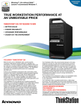
UNDER TABLE SOLUTIONS
UT240-313 Shown Above
MANUAL PART NUMBER: 400-0491-002
UT SERIES
UNDER THE TABLE INTERCONNECT
SOLUTIONS FOR AUDIOVISUAL SIGNALS
USER’S GUIDE
UNDER TABLE SOLUTIONS
TABLE OF CONTENTS
This manual covers the following ALTINEX
Under-the-Table (UT) models:
Page
PRECAUTIONS / SAFETY WARNINGS................ 2
GENERAL..........................................................2
HANDLING ........................................................2
CLEANING.........................................................2
FCC NOTICE .....................................................2
ABOUT YOUR UT-SERIES...................................... 3
TECHNICAL SPECIFICATIONS.............................. 3
PRODUCT DESCRIPTION ...................................... 4
APPLICATION DIAGRAMS...................................... 5
DIAGRAM 1: TYPICAL SETUP ..........................5
DIAGRAM 2: UT240-310 US/CANADA...............6
DIAGRAM 3: UT240-311 US/CANADA...............6
DIAGRAM 4: UT240-312 US/CANADA...............7
DIAGRAM 5: UT240-313 US/CANADA...............7
DIAGRAM 6: UT240-410 EUROPE ....................8
DIAGRAM 7: UT240-411 EUROPE ....................8
DIAGRAM 8: UT240-450 ENGLAND ..................9
DIAGRAM 9: UT240-451 ENGLAND ..................9
DIAGRAM 10: UT240-510 AUSTRALIA............10
DIAGRAM 11: UT240-511 AUSTRALIA............10
DIAGRAM 12: UT240-550 UNIVERSAL ...........11
DIAGRAM 13: UT240-551 UNIVERSAL ...........11
DIAGRAM 14: CIRCUIT BREAKER..................12
INSTALLING YOUR UT-SERIES ......................... 13
OPERATION ............................................................. 14
CIRCUIT BREAKER RESET ............................14
TROUBLESHOOTING GUIDE............................... 14
ALTINEX POLICIES ................................................ 14
LIMITED WARRANTY/RETURN POLICIES .....14
CONTACT INFORMATION ..............................14
400-0491-002
UT240-310 AV Connect
(2xVGA, 2xAudio,4x Net, 2xPwr)
UT240-311 IT Connect
(4x Net, 2xPwr)
UT240-312 IT Connect
(4x Net, 4xPwr)
UT240-313 AV Connect
(2xVGA, 2xDVI, 2xAud,4x Net, 2xPwr)
UT240-410 IT Connect Europe
(4x Net, 4xPwr, 1xCircuitBreaker)
UT240-411 AV Connect Europe
(2xVGA, 2xAudio, 4x Net, 2xPwr)
UT240-450 IT Connect England
(4x Net, 4xPwr, 1xCircuitBreaker)
UT240-451 AV Connect England
(2xVGA, 2xAudio, 4x Net, 2xPwr)
UT240-510 IT Connect Australia
(4x Net, 4xPwr, 1xCircuitBreaker)
UT240-511 AV Connect Australia
(2xVGA, 2xAudio, 4x Net, 2xPwr)
UT240-550 IT Connect Universal
(4x Net, 4xPwr, 1xCircuitBreaker)
UT240-551 AV Connect Universal
(2xVGA, 2xAudio, 4x Net, 2xPwr)
1
UNDER TABLE SOLUTIONS
PRECAUTIONS / SAFETY WARNINGS
1.4 FCC NOTICE
1
Please read this manual carefully before using your
UT-SERIES Interconnect. Keep this manual handy
for future reference. These safety instructions are
to ensure the long life of your UT-SERIES
Interconnect and to prevent fire and shock hazards.
Please read them carefully and heed all warnings.
•
1.1 GENERAL
•
•
There are no user serviceable parts inside.
Qualified ALTINEX service personnel must
perform all service on the UT-SERIES.
1.2 HANDLING
•
•
•
•
•
For best results, place the UT-SERIES on a flat,
leveled surface in a dry area away from dust and
moisture.
To prevent fire or shock, do not expose this unit
to water or moisture. Do not place the
UT-SERIES in direct sunlight, near heaters, or
heat-radiating appliances, or near any liquid.
Exposure to direct sunlight, smoke, or steam can
harm internal components.
Handle the UT-SERIES carefully. Dropping or
jarring can damage the unit.
Do not pull any cables that are attached to the
UT-SERIES.
Do not place heavy objects on top of the
UT-SERIES.
•
1.3 CLEANING
•
•
Unplug the UT-SERIES before cleaning.
Clean only with a dry cloth. Never use strong
detergents or solvents such as alcohol or
thinner. Do not use a wet cloth or water to clean
the unit. Do not open the unit to clean.
400-0491-002
2
This device complies with Part 15 of the FCC
Rules. Operation is subject to the following two
conditions: (1) This device may not cause
harmful interference, and (2) this device must
accept any interference received, including
interference that may cause undesired
operation.
This equipment has been tested and found to
comply with the limits for a Class A digital
device, pursuant to Part 15 of the FCC Rules.
These limits are designed to provide reasonable
protection against harmful interference when the
equipment is operated in a commercial
environment. This equipment generates, uses,
and can radiate radio frequency energy and if
not installed and used in accordance with
instructions found herein, may cause harmful
interference to radio communications. Operation
of this equipment in a residential area is likely to
cause harmful interference in which case the
user will be required to correct the interference
at his own expense.
Any changes or modifications to the unit not
expressly approved by ALTINEX, Inc. could void
the user’s authority to operate the equipment.
UNDER TABLE SOLUTIONS
ABOUT YOUR UT-SERIES
2
TECHNICAL SPECIFICATIONS
3
Specifications are subject to change.
See www.altinex.com for up-to-date information.
UT-SERIES
Under-the-Table AV Interconnects
FEATURES/
DESCRIPTION
PASS-THROUGH
CONNECTIONS
The ALTINEX UT-Series of Under-the-Table AV
Interconnects provide a wide variety of options for
routing computer audiovisual signals, network
connections, and AC power. Under-the-table
options are ideal for situations where it is too
expensive or impractical to install the routing
interface directly into the furniture.
UT-Series Interconnects are available in both US
and international versions. The US versions provide
standard NEMA 5-15R receptacles. International
versions include AC receptacles for Europe,
England, and Australia.
Additionally, the
UT240-550 and UT240-551 include universal AC
receptacles that accept various types of AC plugs.
US and international models UT240-312,
UT240-410,
UT240-450,
UT240-510,
and
UT240-550 also include a push-to-reset 15A circuit
breaker for added protection.
TM-SERIES
UT240-311 (US)
CAT-6 (RJ-45) female (4)
AC receptacle
(2)
UT240-313 (US)
15-pin HD female
24-pin DVI female
3.5mm stereo
CAT-6 (RJ-45) female
AC receptacle
(2)
(2)
(2)
(4)
(2)
UT240-310 (US)
UT240-411 (Europe)
UT240-451 (England)
UT240-511 (Australia)
UT240-551 (universal)
15-pin HD female
CAT-6 (RJ-45) female
3.5mm stereo
AC receptacle
(2)
(4)
(2)
(2)
UT240-312 (US)
UT240-410 (Europe)
UT240-450 (England)
UT240-510 (Australia)
UT240-550 (universal)
CAT-6 (RJ-45) female (4)
AC receptacle
(4)
15A Circuit Breaker
(1)
Table 1. TM-SERIES General
MECHANICAL
TM-SERIES
T° Operating
See drawings in the Diagrams
section for dimensions.
10°C-35°C
T° Maximum
50°C
Dimensions
Humidity
90% non-condensing
Table 2. TM-SERIES Mechanical
ELECTRICAL
Pass-Through Signals
Pass-Through AC
TM-SERIES
All standard audio, video,
network, and modem
signals are acceptable.
600W max.
Table 3. TM-SERIES Electrical
400-0491-002
3
UNDER TABLE SOLUTIONS
PRODUCT DESCRIPTION
4
The UT240 Series offers different connector options for varying degrees of functionality. The UT240-310
and UT240-312 are available with AC receptacles for different regions including Europe, England, and
Australia, as well as a universal connector option. See the Diagrams section for options and details.
UT240-310
UT240-411 Europe
UT240-511 Australia
AC (2)
Net (4)
VGA (2)
Audio (2)
UT240-451 England
UT240-551 Universal
UT240-312
UT240-410 Europe
UT240-510 Australia
UT240-450 England
UT240-550 Universal
AC (4)
Net (4)
Circuit Breaker (1)
* The circuit breaker is located on the inside of the left-hand side
of each unit as viewed from the front. (see Diagram 14)
UT240-311
AC (2)
Net (4)
UT240-313
400-0491-002
AC (2)
Net (4)
VGA (2)
DVI-I (2)
Audio (2)
4
UNDER TABLE SOLUTIONS
APPLICATION DIAGRAMS
5
DIAGRAM 1: TYPICAL SETUP
UT240 SERIES
UT240-310 SHOWN ABOVE
400-0491-002
5
UNDER TABLE SOLUTIONS
DIAGRAM 2: UT240-310 US/CANADA
1.850"
[47mm]
9.400"
[239mm]
2.300"
[58mm]
3.095"
[79mm]
10.400"
[264mm]
DIAGRAM 3: UT240-311 US/CANADA
1.850"
[47mm]
6.636"
[169mm]
2.300"
[58mm]
3.095"
[79mm]
7.636"
[194mm]
400-0491-002
6
UNDER TABLE SOLUTIONS
DIAGRAM 4: UT240-312 US/CANADA
1.850" [47mm]
9.400"
[239mm]
2.300"
[58mm]
3.095"
[79mm]
10.400"
[264mm]
DIAGRAM 5: UT240-313 US/CANADA
10.596" [269mm]
2.300"
[58mm]
3.095"
[79mm]
11.596"
[295mm]
400-0491-002
7
UNDER TABLE SOLUTIONS
DIAGRAM 6: UT240-410 EUROPE
2.450"
[62mm]
13.294"
[338mm]
2.300"
[58mm]
3.095"
[79mm]
14.294"
[363mm]
DIAGRAM 7: UT240-411 EUROPE
2.450"
[62mm]
11.400"
[290mm]
2.300"
[58mm]
3.095"
[79mm]
12.400"
[315mm]
400-0491-002
8
UNDER TABLE SOLUTIONS
DIAGRAM 8: UT240-450 ENGLAND
2.450"
[62mm]
13.294"
[338mm]
2.300"
[58mm]
3.095"
[79mm]
14.294"
[363mm]
DIAGRAM 9: UT240-451 ENGLAND
2.450"
[62mm]
11.400"
[290mm]
2.300"
[58mm]
3.095"
[79mm]
12.400"
[315mm]
400-0491-002
9
UNDER TABLE SOLUTIONS
DIAGRAM 10: UT240-510 AUSTRALIA
2.450"
[62mm]
13.294"
[338mm]
2.300"
[58mm]
3.095"
[79mm]
14.294"
[363mm]
DIAGRAM 11: UT240-511 AUSTRALIA
2.450"
[62mm]
11.400"
[290mm]
2.300"
[58mm]
3.095"
[79mm]
12.400"
[315mm]
400-0491-002
10
UNDER TABLE SOLUTIONS
DIAGRAM 12: UT240-550 UNIVERSAL
2.450"
[62mm]
13.294"
[338mm]
2.300"
[58mm]
3.095"
[79mm]
14.294"
[363mm]
DIAGRAM 13: UT240-551 UNIVERSAL
2.450"
[62mm]
11.400"
[290mm]
2.300"
[58mm]
3.095"
[79mm]
12.400"
[315mm]
400-0491-002
11
UNDER TABLE SOLUTIONS
DIAGRAM 14: CIRCUIT BREAKER
Model
numbers
UT240-312,
UT240-410,
UT240-450, UT240-510, and UT240-550 include a
15A circuit breaker. The circuit breaker is located in
the same location for each model. The UT240-312
is shown here.
CIRCUIT BREAKER
Push to reset.
400-0491-002
12
UNDER TABLE SOLUTIONS
INSTALLING YOUR UT-SERIES
6
BASIC INSTALLATION
Step 1. Locate the best position for the UT-Series
Interconnect, but do NOT mount it to the
surface until all the cables are prepared.
INSTALLATION OPTIONS
The UT Series can be installed horizontally or
vertically as shown. Typically, units are installed
under a table-top, but in some cases, it may be
desirable to install a unit inside a desk opening, or
on the back of a desk or podium.
Step 2. Prepare the mating cables using
high-quality cables for best results and
durability. Make sure the cables are long
enough to allow for a service-loop and so
the cables can be neatly routed beneath
the table to their destinations.
TABLE TOP (SIDE VIEW)
Step 3. Prepare the network cables using the
CAT-6 (RJ-45) connectors provided with
the unit.* The connectors are high-quality
snap-in connectors and do not require any
tools for installing them into the UT
interconnect.
INSIDE DESK (SIDE VIEW)
The connectors are provided with the unit
but do not include cables. ALTINEX
recommends
a
telecommunications
contractor wire the network connectors
and verify proper operation before
connecting them to the UT interconnect.
SNAP-IN
Squeeze the snap-in and
then tilt the connector
back to remove from the
chassis.
LOCK
Step 4. Secure the unit under the table using the
metal screws provided with the unit.
BACK OF DESK/PODIUM (TOP VIEW)
Step 5. Make any necessary connections to the
snap-in connectors.
Step 6. Use cable-ties to secure the cables to the
mounting shelf. Insert the ties through the
holes on the bottom of the unit.
DESK SURFACE
Step 7. Use the cable clamps provided to secure
the cables to the bottom of the table/desk.
* Please visit our website: www.altinex.com for
information related to the pin out of the cables.
400-0491-002
13
UNDER TABLE SOLUTIONS
OPERATION
7
TROUBLESHOOTING GUIDE
The UT-SERIES requires no adjustments for
performance. Once set-up, the UT-SERIES will
work trouble-free without user intervention.
We have carefully tested and found no problems in
the supplied UT-SERIES; however, if you
experience any problems or have questions, call
ALTINEX at (714) 990-2300.
7.1 CIRCUIT BREAKER RESET
The UT240-312, UT240-410, UT240-450,
UT240-510, and UT240-550 include a
push-to-reset 15A circuit breaker. The circuit
breaker is accessible from the left-hand side of
the unit as viewed from the front. In the event
the circuit breaker is tripped, do the following:
ALTINEX POLICIES
9
9.1 LIMITED WARRANTY/RETURN POLICIES
Please see the ALTINEX website at
www.altinex.com for details on warranty and
return policies.
• Disconnect all AC devices from the UT240
9.2 CONTACT INFORMATION
• Turn off the power switch of each AC device
ALTINEX, Inc.
• Push the circuit breaker reset button back in
592 Apollo Street
• Reconnect the AC devices
Brea, CA 92821 USA
• One at a time, turn on the AC devices
TEL: 714 990-2300
TOLL FREE: 1-800-ALTINEX
WARNING
WEB: www.altinex.com
If the circuit breaker trips again, find the device
that is drawing excessive current. Check the
ratings for each of the devices connected to the
UT240. If a device requires a significant amount
of power, it should be plugged into its own
supply circuit.
400-0491-002
8
E-MAIL: [email protected]
14