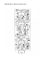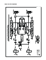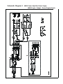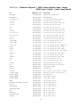
1
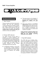
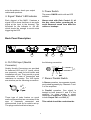
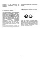
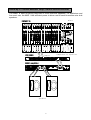
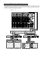
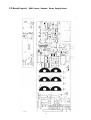
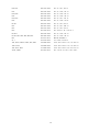
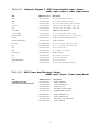
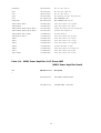
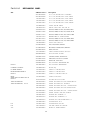
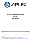
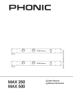
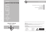
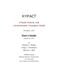
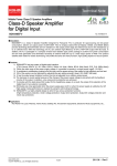
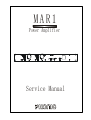
MAR1
Power Amplifier
Service Manual
23
SAFETY FIRST!
WARNING - TO REDUCE THE RISK OF FIRE OR ELECTRIC SHOCK, DO NOT EXPOSE THIS
APPLIANCE TO RAIN OR MOISTURE.
WATER AND ELECTRICITY DO NOT MIX. Keep this unit away from water. If water or other liquids
are spilled on or into this unit, unplug the power cord immediately from the wall socket (with DRY
HANDS) and get a qualified service technician to check it out before using. Keep this unit away from
heaters, radiators and other heat producing devices.
DO NOT ATTEMPT TO SERVICE THIS UNIT. ONLY A QUALIFIED SERVICE TECHNICIAN
SHOULD OPEN THIS UNIT FOR SERVICING.
CAUTION
RISK OF ELECTRIC SHOCK
DO NOT OPEN
The lightning flash with arrowhead symbol, within an equilateral
triangle, is intended to alert the user to the presence of
uninsulated “ dangerous voltage: within the product’s enclosure
that may be of sufficient magnitude to constitute a risk of
electric shock.
The exclamation point within an equilateral triangle is intended
to alert the user to presence of important operating and
maintenance (servicing) instructions in the literature
accompanying the appliance.
CAUTION: TO REDUCE THE RISK OF ELECTRIC SHOCK, DO NOT REMOVE
COVER (OR BACK). NO USER-SERVICEABLE PARTS INSIDE. REFER
SERVICING TO QUALIFIED SERVICE PERSONNEL.
KEEP IT CLEAN: Dust, dirt and debris can interfere with the performance of this product.
Make a special effort to keep this unit away from dusty, dirty environments. Cover the
unit when not in use. Dust it regularly with a soft, clean brush. Careful attention to these
details will be time well spent, and this product will reward you with years of trouble free
operation.
1
Introduction
Congratulations on your purchase of the Phonic MAR 1 Reference Amplifier. Like other
Phonic MAR series power amplifiers – MAR 2/4/6, this unit is designed to provide a good
combination of power, audio clarity, reliability and durability. Especially, optimized for
studio monitoring applications and moderate-power live performance setups, the amps
main features include:
l
150 watts per channel into 4 ohms, 100 watts per channel into 8 ohms
l
Front panel LED Indicators for Protect, Clip & Signal
l
Detented dB gain controls
l
Built-in protection system for short circuit, DC, and temperature monitoring
l
Power-up muting
l
-26dB signal presence LEDs on each channel
l
Quality Neutrik combo Input connectors for professional use
l
Stereo/Parallel switch
l
Ground floating switch
l
Massive, custom-designed extruded heat sinks ( individual for each channel) for
cool operation
l
No Ventilation fan is needed, allowing for quiet operation and reduced ambient noise
in the studio.
l
Extremely low noise and distortion, suitable for quiet applications such as recording
studio, church and museum.
Precautions
1. When first powering-up the amp, keep the amplifier Gain Controls all the way off, in
order to block potentially damaging or annoying sounds caused by defective cables or
hookups. When turning up the Gain, do it gradually, until normal operation is verified.
These precautions are necessary with all high-power amplifiers, since they have
enough power to blow most speakers in abnormal situations.
2. Check the AC Voltage before connecting the AC plug.
3. The amplifier is protected from surges in power-line voltage by the fuses. Should your
unit ever fail to power-up, first unplug the power cord, and then replace the fuse with
exact type and value.
About This Manual
Please be reminded that a power amplifier is a high-current, high-power device
and should be treated with respect and care. Please read this manual before
connecting and operating your unit and file it in a safe place for future reference.
2
MAR 1 Power Amplifier
4
3
2
1
5
Front Panel Description
l
Thermal protection on the heatsink: If
the amp overheats, thermal shutdown
protects the circuitry until the
temperature is reduced to a safe
level.
l
Short circuit protection: The Protect
LED Indicator will also light up if the
speaker terminals are short circuited,
or the impedance of the load is too
low. In these circumstances, the
Protect LED will stay on until the fault
condition is rectified.
1. Gain Controls
These two knobs are the level controls for
Channel one and two respectively.
Turning clockwise will increase its gain,
and counter clockwise will decrease its
gain. Please always power-up with the
volume all the way down, and increase
volume slowly to make sure that no
conditions exist which could annoy your
audience or harm your speakers.
Some protection situations require the
amplifier to be switched off and then
back on for normal operating
conditions to be restored.
2. Protect LED Indicator
The MAR1 features several types of
protection to prevent damage to the
circuitry during turn-on or fault conditions.
If the LEDs light up, this indicates that one
of the various protections is safeguarding
the different sections of the amplifier and
in these cases, the power output is
normally switched off until normal
operating conditions are restored.
l
3. Clip LED Indicator
The LEDs light up at clipping status,
whenever any conditions occur that could
leak to non-linearility, such as an out-ofspec load and waveform distortion.
Because of the MAR 1’s ability to enter
and exit clipping with as few audible
artifacts as possible, you may not hear
any distortion even if the indicator flashes.
In general, a few flashes every now and
then will not be a problem. However, if
the LEDs flash often or remain on for any
extended period of time, then turn down
the volume controls to reduce the signal
level going to the MAR 1. If this doesn’t
Loudspeaker protection: in the event
of malfunction, a sensor located on
the power outputs is able to break the
circuit avoiding that current peaks
reach the speakers and damage
them.
3
solve the problem, check your output
cables and speakers.
5. Power Switch
4. Signal “Status” LED Indicator
The power ON/Off switch with an LED
indicator.
Always start with Gain Control (1) all
the way down before powering-up to
avoid abnormal sound from defective
cables or hookups.
Each channel of the MAR 1 features a
signal LED to show that there is an audio
signal at the input to the channel. The
threshold for the indicator is –26 dB,
which should be enough to avoid noise
triggering the LED.
Back Panel Description
9
8
the following convention:
6. Ch1/Ch2 Input (Neutrik
Connector)
Quality Neutrik Connectors are provided
for balanced XLR and 1/4” inputs, which
are commonly, used for both mobile and
installation set-ups. They provide a good
combination of ease of connection and
resistance to corrosion. The XLR inputs
are wired as per the following convention:
+
6
7
tip
+
ring sleeve
-
gnd
7. Stereo/ Parallel Switch
In Stereo operation, two separate signals
are treated separately by Channels 1 and
2 of the amplifiers.
-
In Parallel operation, One signal is
treated by both channel 1 and 2 of the
amplifier. In other words, a signal
connected to Input Ch1 or Ch2 (6) is sent
to both Output Ch1 and CH2 (9).
gnd
These type of jacks feature on much
audio equipment and are convenient if the
amp is frequently connected and
disconnected, such as for mobile set-up.
The plugs used should wired as per
This switch should be used when the
4
to keep the switch in the “Ground On”
position,
Amplifier is off; otherwise the
speakers’ components could be
damaged.
9. Binding Post Output Ch1/ Ch2
8. Ground Lift Switch
This switch allows the circuit and chassis
grounds to be separated in case on a
ground conflict. In normal use the switch
should be in the Ground On position.
Lifting the ground (Floating position) may
resolve the ground conflict, but which
means that circuit grounding depends on
other
connected
components.
Deficiencies in other components’
grounding will affect the sound and a
serious electric fault with the amplifier
could damage other components in the
system.
Speaker
Speaker
These are suitable for banana plugs,
spade lugs or bare wires. Spade lugs and
bare wires should both be screwed done
tightly to exclude oxygen, and care should
be taken to avoid loose strands of wire
that may cause short circuits.
For the best combination of safety and
performance,it is highly recommended
5
Hook-up #1 Studio Monitor Amp/ Sound Reinforcement
The MAR1 is ideal for driving near-field or other reference speakers. For auditorium and
live music use, the MAR 1 has sufficient power to drive a set of small-to-medium size club
speakers.
IMPACT 16
mixer
outputs
PEQ 3400
inputs
outputs
MAR1 amplifier
speakers
6
compressor or equalizer
Hook-up #2 Bi-Amp Sound Reinforcement
Biamplification often provides better live sound and greater efficiency by splitting the audio
signal into two different channels. One MAR1 drives a low frequency speaker system and
the other, a high frequency speaker system.
Impact 12
High
Frequency
Outputs
Low
Frequency
Output
Crossover
Ins
High Frequency MAR1
Low Frequency MAR1
Low Frequency Speakers
High Frequency Speakers
7
Specifications
Frequency response (1W/ 8 ohms)
20 – 20kHz (+ 1 dB)
Power bandwidth (100W/ 8 ohms)
20 – 20kHz (+ 1 dB)
Total harmonic distortion
< 0.3 % (100W/8 ohms, 10Hz – 20kHz)
<0.5 % (120W/4 ohms, 10Hz – 20kHz)
Signal to noise ratio (IHF-A)
> 100 dB
Slew rate
25 V/us
Damping factor
> 150
(Rate output: 100W/8ohms @1kHz)
Crosstalk (Rate output: 100W/8ohms @1kHz) >75 dB
Rated Power
100W
(8 ohms, both channel driven)
Max. Output Power
4 ohms, 1kHz, 1% T.H.D. both drive
150W
8 ohms, 1kHz, 1% T.H.D. both drive
120W
Input sensitivity
0.775V
8 ohms, 1kHz, @ rated power 100W
30k ohms (balanced)
Input impedance
15k ohms (unbalanced)
Voltage Gain
31.2 dB
Max. Noise
<0.6 mV
Protection circuits
l
Output offset voltage protection
l
Heat sink overheat protection
l
Transformer overheat protection
l
Load shorting protection
l
Power on/off protection
AC power requirement
120V/ 60Hz or 230V/50Hz
Dimensions (mm)
480x338x54(WxDxH)
Net Weight
9.5 Kg
E & OE. Due to continual product development, all features and specifications subject to change without notice
8
PC-Board Layout MAR1 Input / Output & Power Supply Board
9
PC-Board Layout MAR1 Power Amplifier Board
10
MAR1 BLOCK DIAGRAM
11
Schematic Diagram 1 MAR1 Power Amplifier Input / Output
(MAR1 Input / Output & Power Supply Board)
12
Schematic Diagram 2 MAR1 Power Amplifier Power Supply
(MAR1 Input / Output & Power Supply Board)
13
Schematic Diagram 3
MAR1 Power Amplifier ch1/2 Power AMP
(MAR1 Power Amplifier Board)
14
Parts List Schematic Diagram 1 MAR1 Power Amplifier Input / Output
(MAR1 Input / Output & Power Supply Board)
Ref.
PHONIC Part #
Description
BD1, BD2
090-10000-000-0
SEMI, DIODE, BRIDGE, PB154
BD1, BD2 *2
322-05000-100-0
TUBE, 5mm*D1
C1, C2, C14, C15
042-22024-020-0
CAP, CERAMIC, TYPE2, 50V, 22pF, 5%
C17, C20
030-47556-0A0-0
CAP, ELEC, 85C, 50V, 4.7μF, 20%
C18, C22
030-22738-001-0
CAP, ELEC, 85C, 25V, 220μF, +80%, -20%
C19, C26
030-10626-0A0-0
CAP, ELEC, 85C, 16V, 10μF, 20%
C25
030-10564-0A0-0
CAP, ELEC, 85C, 63V, 1μF, 5%
C27
030-22538-0A0-0
CAP, ELEC, 85C, 25V, 2.2μF, +80%, -20%
C29, C30
042-22426-000-0
CAP, CERAMIC, TYPE2, 50V, 0.22μF, 20%
C3, C7, C8, C16
030-22628-0A0-0
CAP, ELEC, 85C, 16V, 22μF, +80%, -20%
C4, C5, C11, C12
042-10426-050-0
CAP, CERAMIC, TYPE2, 50V, 0.1μF, 20%
C6, C10
042-33024-001-0
CAP, CERAMIC, TYPE2, 50V, 33pF, 5%
C9, C13
030-22556-0A0-0
CAP, ELEC, 85C, 50V, 2.2μF, +80%, -20%
CN1A, CN1B
211-10021-180-0
CONN, 1/4", WAFER, SOCKET, 3-PIN,
CN1A, CN1B
212-10032-330-0
CONN, 1/4", WAFER, PLUG, 3-PIN,
CN2A, CN2B
211-10024-110-0
CONN, 1/4", WAFER, SOCKET, A3963WV2-2P
CN3A
212-10090-330-0
CONN, 1/4", WAFER, PLUG,9-PIN, 170mm
CN3B
212-10090-340-0
CONN, 1/4", WAFER, PLUG,9-PIN, 370mm
CN4A
211-10081-130-0
CONN, 1/4", WAFER, SOCKET, 8-PIN, 2532-08
CN4A-1-2
212-10080-420-0
CONN, 1/4", WAFER, PLUG,8-PIN, 270mm
CN4B
211-10091-160-0
CONN, 1/4", WAFER, SOCKET, 9-PIN
CN4B-1-2
212-10090-320-0
CONN, 1/4", WAFER, PLUG,9-PIN, 270mm
CN5
212-10023-060-0
CONN, 1/4", WAFER, PLUG, 2-PIN,
CN5
211-10021-160-0
CONN, 1/4", WAFER, SOCKET, 2-PIN
D1, D2
090-02000-020-0
SEMI, DIODE, DETECTOR, 1N4148
D3
090-01512-000-0
SEMI, DIODE, ZENER, 5.1V, 0.5W, ±10%
D4, D5
090-00002-001-0
SEMI, DIODE, 1N4002
IC1, IC2
160-00000-900-0
IC, 4558DY, JRC
J1A, J1B
211-03300-170-0
CONN, 1/4",XLR-JACK, NCJ6FK-V, NEUTRIK
L1_R69, L2_R70
075-10082-100-0
INDUCTOR, 1uH, ±10%, AXIAL(4.7Ω, 3W)
LED1A, LED1B
100-00010-030-1
LED, SE3011, RED
LED2A, LED2B
100-00040-030-0
LED, EL204YT, YELLOW
LED3A, LED3B
100-00050-110-0
LED, EL204GT, GREEN
LED4
100-00010-030-1
LED, SE3011, RED, 3mm
R1, R2, R4, R5, R18, R21, R22, R25
006-15020-440-0
RES, MF, 1/16W, 15K, ±1%
R11, R27
000-10126-400-0
RES, CF, 1/4W, 100K, 5%
R20, R38, R47
000-22206-400-0
RES, CF, 1/16W, 2.2K, 5%
R26, R33, R34, R42
000-10326-400-0
RES, CF, 1/4W, 10K, 5%
R28
000-10226-400-0
RES, CF, 1/4W, 1K,5%
R29, R44
000-47206-400-0
RES, CF, 1/16W, 4.7K, 5%
R3, R10, R13, R15
000-10206-400-0
RES, CF, 1/16W, 1K, 5%
R30, R57
000-18226-400-0
RES, CF, 1/4W, 1.8K, 5%
15
R32, R53
000-12326-400-0
RES, CF, 1/4W, 10K, 5%
R35
000-33306-400-0
RES, CF, 1/16W, 33K, 5%
R36, R40
000-47306-400-0
RES, CF, 1/16W, 47K, 5%
R54
000-18306-400-0
RES, CF, 1/16W, 18K, 5%
R56, R59
000-18226-400-0
RES, CF, 1/4W, 1.8K, 5%
R58
000-10106-400-0
RES, CF, 1/16W, 100, 5%
R6, R7
000-82326-400-0
RES, CF, 1/4W, 82K, 5%
R63
000-15426-400-0
RES, CF, 1/4W, 150K, 5%
R65
000-33326-400-0
RES, CF, 1/4W, 33K, 5%
R66
003-33003-601-0
RES, CEMENT, 5W, 0.330, 5%, U
R8, R12
000-43306-400-0
RES, CF, 1/16W, 43K, 5%
R9, R14, R31, R37, R46, R60, R62
000-10306-400-0
RES, CF, 1/16W, 10K, 5%
RL1
076-01212-012-0
RELAY, VB12MU-5
SW1
210-01202-050-0
SW, SLIDE, SSFZ22-07
TR1, TR3-6, TR8-10, TR13, R15, TR16
120-00000-800-0
SEMI, TRANSISTOR, NPN, 2SC1815, GR
TR17, TR19
120-00000-800-0
SEMI, TRANSISTOR, NPN, 2SC1815, GR
TR7, TR11, TR12
121-00000-200-0
SEMI, TRANSISTOR, PNP, 2SA1015, GR
VR1A, VR1B
022-20370-010-0
RES, SIGNAL, ROTARY, 13mm, 20KA
16
Parts List Schematic Diagram 2 MAR1 Power Amplifier Input / Output
(MAR1 Input / Output & Power Supply Board)
Ref.
PHONIC Part #
BD3
090-10015-000-0
SEMI, DIODE, BRIDGE, KBL06
BD4
090-10013-000-0
SEMI, DIODE, BRIDGE, PUB605
C31
058-68325-100-0
CAP, LINE, 250V, 0.068μF, 20%, MEX-683K
C32-C37
030-33866-030-0
CAP, ELEC, 85C, 63V, 3300μF, +80%, -20%
C38
030-10838-000-0
CAP, ELEC, 85C, 25V, 1000μF, +80%, -20%
CH1, CH2
211-17000-410-0
BINKING POST BP-47-2P
CN2/4, CN4B
211-10044-040-0
CONN, 1/4", WAFER, SOCKET, 4-PIN
FUSE1-FUSE5
280-63267-000-0
FUSE, 6.3A (250V VERSION ONLY), VDE/CE, S
FUSE5
280-3E216-001-0
FUSE, 3.15A, 250V, SSA, BEL5ST3.15
POWER SWITCH/*2
322-21500-400-6
TUBE, 15mm*D4
PS1, PS3
211-24503-000-0
CONN, 1/4", SCREW, TERMINAL, 5-PIN
PS2
211-24903-000-0
CONN, 1/4", SCREW, TERMINAL,9-PIN
R39
000-10326-400-0
RES, CF, 1/4W, 10K, 5%
R52
003-33003-600-0
RES, CEMENT, 5W, 330, 5%,
R52, R55 *2
322-05000-100-0
TUBE, 5mm*D1
R55
003-18003-600-0
RES, CEMENT, 5W, 180, 5%,
SW2
210-01202-050-0
SW, SLIDE, SSFZ22-07
SWITCH POWER
210-03201-004-0
SW, PUSH, POWER
T1
070-20338-800-0
POWER, TRANSFORMER, 115/230V
Parts List
Description
MAR1 Power Amplifier Input / Output
(MAR1 Input / Output & Power Supply Board)
Ref.
PHONIC Part #
POWER AMPLIFIER
INPUT/OUTPUT BOARD MAR1
F34-10000-002-0
Description
MAR1, PCB-INPUT
281-00000-020-0
FUSE, CLIP, FH-1206
315-00016-000-0
GND, LUG, JG-6L
290-34340-200-0
PCB, MAR1, INPUT, PANEL
382-10005-010-0
TINNER, WIRE, 5mm, D0.6
H34-10002-002-0
MAR1, PCB-INPUT, A/I
F34-10000-003-0
MAR1, PCB-LED, M/I
290-34340-300-0
PCB, MAR1, VR+LED, PANEL
H34-10003-003-0
MAR1, PCB-LED
17
Parts List Schematic Diagram 3 MAR1 Power Amplifier ch1/2 Power AMP
(MAR1 Power Amplifier Board)
PHONIC Part #
Description
C101 ,C126
042-47225-050-0
CAP, CERAMIC, TYPE2, 50V, 4700pF, 5%
C102, C109, C122, C128
042-47144-050-0
CAP, CERAMIC, TYPE2, 100V, 470pF, 5%
C103, C129
042-47124-050-0
CAP, CERAMIC, TYPE2, 50V, 470pF, 5%
C104
030-22736-0A0-0
CAP, ELEC, 85C, 25V, 220μF, 20%
C104
322-05000-100-0
TUBE, 5mm*D1
C104
322-05000-100-0
TUBE, 5mm*D1
C105, C125
042-10424-050-0
CAP, CERAMIC, TYPE2, 50V, 0.1μF, 5%
C106, C124
042-10444-050-0
CAP, CERAMIC, TYPE2, 100V, 0.1mF, 5%
C107, C123
030-47668-0A0-0
CAP, ELEC, 85C, 63V, 47μF, +80%, -20%
C108, C121
046-10214-060-0
CAP, MYLAR, 100V, 0.001μF, 5%
C110, C120
042-10144-050-0
CAP, CERAMIC, TYPE2, 100V, 100pF, 5%
C111
042-33024-050-0
CAP, CERAMIC, TYPE2, 50V, 33pF, 5%
C112, C118
046-10204-050-0
CAP, MYLAR, 50V, 0.001μF, 5%
C113, C114
046-47304-001-0
CAP, MYLAR, 50V, 0.047μF, 5%
C115, C116, C119
030-10658-0A0-0
CAP, ELEC, 85C, 50V, 10μF, +80%, -20%
C117
032-10636-000-0
CAP, ELEC, NP, 85C, 25V, 10μF, 20%
C127
030-22736-0A0-0
CAP, ELEC, 85C, 25V, 220μF, 20%
CN101, CN102, CN104
211-10024-110-0
CONN, 1/4", WAFER, SOCKET, 2-PIN, A3963WV-2P
CN103
211-10091-160-0
CONN, 1/4", WAFER, SOCKET, 9-PIN, 2532-09
D101, D102, D105, D106, D113, D115,
D117, D118
D103, D114
090-00002-001-0
SEMI, DIODE, RECT, 1N4002
090-00017-000-0
SEMI, DIODE, RECT, LT6A04
D104, D116
090-01103-010-0
SEMI, DIODE, ZENER, 10V, 0.5W, ±10%
D108, D107, D111, D112
090-02000-020-0
SEMI, DIODE, DETECTOR, 1N4148
D109, D110
090-01752-010-0
SEMI, DIODE, ZENER, 7.5V, 0.5W, ±10%
IC101
160-00018-900-0
IC, MC34081
R101, R108, R145, R149
000-82226-400-0
RES, CF, 1/4W, 8.2K, 5%
R102, R122, R128, R150
000-10326-400-0
RES, CF, 1/4W, 10K, 5%
R103, R151
000-47326-400-0
RES, CF, 1/4W, 47K, 5%
R104, R152
000-33236-400-0
RES, CF, 1/2W, 3.3K, 5%
R105, R153
000-47126-400-0
RES, CF, 1/4W, 470, 5%
R106, R148
000-12326-400-0
RES, CF, 1/4W, 12K, 5%
R107, R154
000-33726-400-0
RES, CF, 1/4W, 3.3, 5%
R109, R147
000-47026-400-0
RES, CF, 1/4W, 47, 5%
R110, R146
000-68236-400-0
RES, CF, 1/2W, 6.8K, 5%
R111, R144
000-27326-400-0
RES, CF, 1/4W, 27K, 5%
R112, R114, R138, R143
000-10126-400-0
RES, CF, 1/4W, 100, 5%
R113, R117, R136, R140
000-22226-400-0
RES, CF, 1/4W, 2.2K, 5%
R115, R134
000-47736-400-0
RES, CF, 1/2W, 4.7, 5%
R116, R121, R123, R137, R130
000-10226-400-0
RES, CF, 1/4W, 1K, 5%
R118, R141
000-10136-400-0
RES, CF, 1/2W, 100, 5%
R119
000-10426-400-0
RES, CF, 1/4W, 100K, 5%
R124, R129
000-68326-400-0
RES, CF, 1/4W, 68K, 5%
Ref.
18
R125,R126
000-39226-400-0
RES, CF, 1/4W, 3.9K, 5%
R127
006-49912-420-0
RES, MF, 1/4W, 4.99K, ±1%
R131
000-82126-400-0
RES, CF, 1/4W, 820, 5%
R132
020-20151-000-0
RES, SEMI-FIX, ROTARY, 200, 0.1W, D10
R133
011-33000-010-0
RES, THERMAL, PTC
R142, R120
003-33093-602-0
RES, CEMENT, 5W, 0.33, 5%
TR101, TR103, TR110
120-00005-000-0
SEMI, TRANSISTOR, NPN, MJE340
TR102, TR106
120-00008-700-0
SEMI, TRANSISTOR, NPN, TIP35
TR102, TR106, TR108, TR113, TR115
590-53008-200-0
SCREW, MACHINE, SET, SCR, M3.0*8, BLK
TR102, TR106, TR108, TR113, TR115
610-60301-006-0
WASHER, SPR, D3*D5*1, NI
TR102, TR106, TR113, TR115
314-00000-050-0
BUSHES, 602S(V.0)
TR104, TR111, TR114
121-00006-100-0
SEMI, TRANSISTOR, PNP, MJE350
TR105
120-00001-200-0
SEMI, TRANSISTOR, NPN, BC550
TR107
120-00001-400-0
SEMI, TRANSISTOR, NPN, 2N5551
TR108
120-00008-800-0
SEMI, TRANSISTOR, NPN, MJE802
TR108
313-00000-060-0
WASHER, RUBBER, TO-2203
TR109
121-00000-300-0
SEMI, TRANSISTOR, PNP, 2N5401, GR
TR112
121-00000-800-0
SEMI, TRANSISTOR, PNP, BC560
TR113, TR115
121-00006-200-0
SEMI, TRANSISTOR, PNP, TUP36
Parts List
MAR1 Power Amplifier ch1/2 Power AMP
(MAR1 Power Amplifier Board)
Ref.
PHONIC Part #
Description
POWER AMPLIFIER BOARD MAR1
F34-10000-001-0
MAR1, PCB-POWER
526-20033-010-0
HEAT, SINK, MAR1
290-34340-100-0
PCB, MAR1, POWER-PANEL
382-20002-510-0
TINNER, WIRE, 2.5mm, D0.6
382-20005-010-0
TINNER, WIRE, 5mm, D0.6
382-20007-510-0
TINNER, WIRE, 7.5mm, D0.6
H34-10001-001-0
MAR1, PCB-POWER
19
Parts List
MECHANISM MAR1
Ref.
PHONIC Part #
212-10010-580-0
212-10010-590-0
Description
CONN, 1/4", WAFER, PLUG,1-PIN,60mm
212-10023-070-0
CONN, 1/4", WAFER, PLUG, 2-PIN, 230mm
CONN, 1/4", WAFER, PLUG, 2-PIN, 230mm
212-10023-080-0
CONN, 1/4", WAFER, PLUG, 2-PIN, 320mm
212-10041-100-0
CONN, 1/4", WAFER, PLUG, 4-PIN, 250/350
321-00000-070-0
CABLE, TIE, HW-100mm
370-08010-733-0
POWER, CORD, 125V, 10A, 2.5m, 3P
379-01800-127-0
MULTY, WIRE, UL1007, #26, 80mm, RED
379-02121-140-0
MULTY, WIRE, UL1007, #24, 120mm, YLW
379-02131-151-0
MULTY, WIRE, UL1007, #24, 130mm, GRN
379-05351-121-0
MULTI, WIRE, UL, 1617#18, 350mm
379-10101-101-0
MULTY, WIRE, UL1015, #18, 100mm, BLK
379-10101-121-0
MULTY, WIRE, UL1015, #18, 100mm, RED
510-20660-000-0
PANEL, MAR1, PHONIC
516-20390-000-0
TOP, COV, MAR1, PHONIC
517-20460-000-0
BOTTOM, COVER, MAR1, PHONIC
525-20003-000-0
FEET, D20*10.4
527-11000-000-0
STRAN, RELIEF, BUSHING, 6W3-4, R
540-20090-000-0
KNOB, ROTARY, PA1100
560-60001-100-0
CARTON, MAR1, 548*428*355
561-60001-100-0
GIFT, BOX, 535*415*155, MAR1
565-60014-000-0
POLYLON, 150*410*87
568-00003-000-0
BAG, PLASTICS, 240*340*0.05, #10
PCB*15
568-30005-000-0
BAG, PLASTICS, 640*530*0.05
CUBOSS*2, XLR/J*4
572-00000-100-0
DRYER, 10g
IC+HEAT SINK*10
573-10060-010-0
LABEL-NO., SERIAL, MAR1
BOTTOM+HEAT SINK*4
573-60012-010-0
LABEL-NO., SERIAL, MAR1
FEET*4
573-60013-000-0
LABEL-NO., SERIAL, MAR1, CE
HEAT
SINK+TOP.COV+BOT.COV*12
FEET*4
573-60018-000-0
LABEL, FUSE, 12*2.5
574-6A006-010-0
OWNER'S, MANUAL, MAR1
TOUTCH GROUND
590-04010-200-0
SCREW, MACHINE, FLT, SCR, M4.0*10, BLACK
590-43006-100-0
SCREW, MACHINE, PAN, M3.0*6, ZN
590-53006-200-0
SCREW, MACHINE, SET, SCR, M3.0*6, BLACK
590-53008-200-0
SCREW, MACHINE, SET, SCR, M3.0*8, BLACK
590-54008-200-0
SCREW, MACHINE, SET, SCR, M4.0*18, BLACK
591-23010-000-0
SCREW, TAPPING, BID, SCR, D3.0*10
610-00301-001-0
WASHER, PLA, D3*D8*1, NI
610-00320-321-0
WASHER, PLA, D3*D8*0.3, NI
610-60300-501-0
WASHER, PAN, SPR, D3.0*D7.0*0.5, NI
615-20002-630-0
COPPER, RIVET, 27+5
F-F
615-20037-630-0
COPPER, RIVET, 25+6, M3
E-E
618-14180-662-0
PIN, SPEC, FIXED, SR-2, WHITE
A-A
631-20019-000-0
HEMECON, D30*D5.5*0.5mm
TOUTCH GROUND,
IC*10
20
B-B
631-60003-000-0
HEMECON, 10*360mm
C-C
B34-34010-230-1
MAR1, PHONIC, AC, 120V, UL/CAS
21
Parts List Power Requirement Classification AC240V SAA
FUSE5
280-3E216-001-0
FUSE, 3.15A, 250V, SSA, BEL5ST3.15
FUSE1-4
280-63267-000-0
FUSE, TSD6.3A, 250V, VDE/UL/CSES
370-12040-839-0
POWER, CORD, 10A, 250V, 2.5m, 3P, SAA
527-11000-000-0
STRAN, RELIEF, BUSHING, 6W3-4, R
619-06380-320-0
PLA, RIVET, ST-3L
Parts List Power Requirement Classification AC240V SA
FUSE1-4
280-3E216-001-0
FUSE, 3.15A, 250V, SSA, BEL5ST3.15
FUSE1-4
280-63267-000-0
FUSE, TSD6.3A, 250V, VDE/UL/CSES
370-12020-829-0
POWER, CORD, 240V, 3A/250V, 3P6F, SA
527-11000-000-0
STRAN, RELIEF, BUSHING, 6W3-4, R
619-06380-320-0
PLA, RIVET, ST-3L
Parts List Power Requirement Classification AC240V BS
FUSE1-4
FUSE1-4
280-3E216-001-0
FUSE, 3.15A, 250V, SSA, BEL5ST3.15
280-63267-000-0
FUSE, TSD6.3A, 250V, VDE/UL/CSES
370-26B40-429-1
POWER, CORD, 230V, 13A, 2.5m, BS, 3P
527-11000-000-0
STRAN, RELIEF, BUSHING, 6W3-4, R
619-06380-320-0
PLA, RIVET, ST-3L
Parts List Power Requirement Classification AC240V IEC
FUSE1-4
280-3E216-001-0
FUSE, 3.15A, 250V, SSA, BEL5ST3.15
FUSE1-4
280-63267-000-0
FUSE, TSD6.3A, 250V, VDE/UL/CSES
370-23060-939-0
POWER, CORD, 10/16A, 250V, 2.5m2P, CE
527-11000-000-0
STRAN, RELIEF, BUSHING, 6W3-4, R
543-10110-120-0
KNOB, ROTARY, BUSHING, D6.0, GRY
619-06380-320-0
PLA, RIVET, ST-3L
22