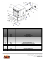
1
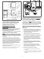
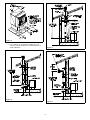
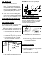
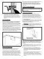
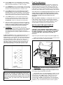
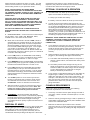
EF3801B-AL Pellet Heater
Installation & Operating Instructions
Please read this entire manual before installation. Save these instructions.
GENERAL INFORMATION
Installation and repair should be done by a qualified service
person. The heater should be inspected before use and at
least annually by a professional service pers on. More
frequent cleaning m ay be re quired due to fuel quality,
excessive lint from carpetin g, bedding m ate rial, etc . It is
impera tive that control com partm ents , burn ers and circulating air passageways of the heater be kept clean.
The EASYFIRE Pellet heater has been designed and
approved for burning w oo d pellet fu el on ly. Burning other
forms of fuel is not permitted and will void all warranties.
This unit has been approved for use with a 3" Type L Pellet
Vent System .
NEVER use gasoline, gasoline-type lantern fuels, kerosene,
charcoal lighter fluid, or similar liquids to start or "freshen
up" a fire. Keep all such liquids well away from the heater
while it is in use.
Ashes must be disposed of in a metal container with a tight
fitting lid and placed on a noncombustible floor or ground,
we ll away from all fu els, pending fina l disposal.
SAFETY NOTICE
< CAUTION: HOT W HILE IN OPERATION. KEEP
CHILDREN, CLOTHING AND FURNITURE AWAY.
CONT ACT MAY CAUSE SKIN BURNS.
< IF THIS HEATER IS NOT PROPERLY INSTALLED,
A HOUSE FIRE MAY RESULT.
< FAILU RE TO CO M PLY W ITH OW NE RS ' MANU AL
INSTRUCTIONS WILL VOID YOUR WARRANTY!
PLEASE READ THIS ENTIRE MANUAL BEFORE
INSTALLATION AND USE OF THIS PELLET FUELBURNING ROOM HEATER. FAILURE TO FOLLOW
TH ESE IN ST RU CT ION S C OU LD RE SU LT IN
PROPERT Y DAMAGE, BODILY INJURY OR EVEN
INSTALLER: PLEASE LEAVE THIS MANUAL WITH
THE OWNER!!
WARNING: THIS HEATER SHOULD NOT BE
INSTALLED IN A SLEEPING ROOM.
NOTE : During the first few burns the high tem perature
paint and sealant used in manufacture will emit some odor
and smoke. Open doors and windows to the outside for
proper ventilation during the first burn cycle and curing of
the paint.
This heate r, when insta lled, m ust be electrically gro unded in
accordance with local codes or, in the absence of local
codes, with the National Electrical Code, ANSI/NFPA 702006.
Provide adequate clearances around air openings into the
combustion chamber and adequate accessibility clearance
for servicing and proper operation. Never obstruct the front
opening of the hea ter.
The heater may be installed as a free-standing unit mounted
on a non-com bustib le protec tive floo r pa d or he arth. O r it
m ay be m ounted into an existing U. L. approved w ood stove
chimney. Non-combustible floor protection is required and
m ust be used when placing the heater on any com bustib le
m ate rial.
The pellet heater must be operated with a power source and
will not operate using natural draft. If there is a powe r failure
the heater will shut down. If the 12 volt back system is installed, the heater will automatically switch to 12 volt power.
The EasyFire Pellet Heater has been listed by OM NI-Test
Laboratories, Inc. to ASTM, U.L.,and EPA Standards.
Sierra Products, Inc.
506 1 Brook s St., S te. B
Montclair, CA 91763
Listed by OMNI-Test Laboratories, Inc.
Rep ort No . 256-S-01-4
Figure 2
W ARN ING : Installatio n of a M ob ile Ho me Attachment Kit
P/N 10412 and outside comb ustion air is mand atory in
mobile or modular home installations although it may
also be used in all residential applications.
Figure 1 -Overall Dimensions
CAU TIO N: D O N OT CO NN EC T T O AN Y AIR
DISTRIBUTION DUCT O R SYSTEM .
An outs ide air inlet MU ST be provided for combustion
and ven tilation air. The air inlet must remain unrestricted
while unit is in use. Outside air connection is located in the
rear of the heater (Figure 2). Use conduit pipe or metal flex
pipe and/or fittings to mak e the air intake hook-up.
VENTING AND INSTALLATION
CLEARANCES
CAUTION: STRUCTURAL INTEGRITY OF THE MO BILE
HOME FLOOR, WALLS AND CEILING/ROOF MUST BE
MAINTAINED.
OU TS IDE CO M BU ST ION AIR IS M AND ATO RY IN
MO BILE OR MO DULAR HOM E INSTALLATIONS.
CONT ACT LOCAL BUILDING OFFICIALS ABOUT RESTRICTIONS AND INSTALLATION INSPECTION
RE QU IREM EN TS IN YOU R AR EA.
1.
W hen deciding on the location of your heater and vent
pipe, try to minimize the alteration and reframing of
struc tural com pon ents of the building . Vent pipe must
be installed so that access is provided for
inspection and cleaning.
2.
Avoid installing heater in high traffic areas. Keep
children well away from the heater when in operation.
3.
A 3" clearance to combustibles must be maintained
for horizontal and vertical venting. W hen passing
through ceilings or walls, you m ust us e a listed wall
thimble, making sure all combustible materials and
insulation products are a minimum of 3" away from the
pellet vent pipe.
4.
A no n-com bu stible he arth pad must be use d if
installed on a carpet, woo d flo or o r oth er co mbu stible material (see Figure 3).
5.
W hen installing the exhaust vent into an existing
chimney, a tee must be installed behind the heater
before going up into the chim ney. This is necessary in
order to remove fly ash accumulation.
6.
Exit termina tion (distanc e to op ening s):
A LISTED, 4" MINIMU M T YPE "L" PELLET VENT PIPE
IS MANDATORY ON ALL INSTALLATIONS.
DO NO T INSTALL A FLUE DAMPER IN THE EXHAUST
VENTING SYSTEM OF THIS UNIT, DO NOT CONNECT
THIS UNIT TO A CHIMNEY FLUE SERVING ANOT HER
APPLIANCE.
Use only listed 3" minimum Type "L" pellet vent and
components for installation. The exhaust vent system
must be attached to the unit and to each adjoining section.
All joints for connector pipe shall be fastened with at least
three screws. If vented horizontally, joints shall be made
gas-tight by sealing with high temperature silicon or
m aterial spec ified by vent pipe m anu facturer. Failure to
use listed pellet vent pipe or install it per m anufacturers
instructio ns will void your warranty.
INSTALL VENT AT CLEARANCES SPECIFIED BY THE
VENT MANU FACTURER
Vent Pipes’ inner and outer diameters may vary. Check
with v ent pipe m anu facturer for further deta ils.
a. 3 ft. minimum above any forced air inlet located
within 10 ft.
b. 4 ft. minimum below and horizontally or 1 ft. minimum
above any door, window or gravity air inlet into any
building.
2
Figure 3
c. 2 ft. m inim um to an adjacen t building and 7 ft.
m inim um abo ve grade whe n loca ted adjac ent to
public walkways.
Figure 5
Figure 4
Figure 6
3
UNIT INSTALLATION
IMPORTANT - Any electrical work performed on the
EA SYFIRE H eater should be done by qualifie d personnel.
Route the power supply cord so that it does not touch
any of the exterior com ponents of the he ater.
1.
W hen exiting through the wall with your type L Pellet
vent pipe, you m ay go straight out through a wall
thim ble. You m ust co nnect a pellet vent te e at this
point and extend the vent pipe at leas t 3' (three feet)
vertically outside to provide good draft and allow the
gases to exit. The tee must have a clean out cap for
inspection and regular cleaning (Figure 4). Horizontal
runs must be limited to 2' (two fe et). A w all band is
required fo r every 4' (four feet) minimum on a vertical
run at an exterior wall.
2.
All pellet vent pipe connections including exit at the
rear of the heater should be sealed with high
tem perature silicone (45 0°) or m eta llic duct tap e. T his
prevents smok e and soot leakage into the living area.
If this is not done, there is a possibility that the room
fan will pick up any leakage and blow it into the room.
Figure 8 Stove Connection Panel
Remote Control Thermostat Installation:
AUTOLITE INSTALLATION INSTRUCTIONS
Th e re m ote therm ostat is designed to autom atic ally
regulate the room temperature from the control panel heat
setting to the “Off” setting base d upon roo m temp erature
and place m ent of the re m ote therm osta t. Rem em ber to
leave the control panel on the "Medium or High" position
when utilizing the wall thermostat feature.
Th e Auto Lite Sys tem is fa cto ry ins talled with th e only
installation requ irem ents being the optiona l therm osta t.
Wall Thermostat Installation:
The wa ll therm osta t is des igned to autom atically regulate
the room tem perature from the control panel heat setting
to the “Off” setting based upon room temperature.
Rem ember to leave the control panel on the "Medium or
High" position when utilizing the wall thermostat feature.
The following is a step by step procedure for installing the
optional remote thermostat. Note connection terminals on
rear of un it (Figure 1,2).
The following is a step by step procedure for installing the
optional wall therm ostat. Note conne ction terminals on left
side of unit at rear (Fig ure 7,8). Use 18/2 therm ostat wire
for the installation.
a. Unplug he ater from wall outlet and 12V DC power!
b. Rem ove factory jump wire and hook up thermostat
wires to terminals (Fig ure 7,8).
Autolite Wiring Diagram
a. Unplug he ater from wall outlet and 12V DC power!
c. Locate thermostat approximately 10 to 12 feet from
heater or in area that requires steady temperature.
b. Mount millivolt style remote receiver box to rear of
stove using double-sided tape.
d. Run thermostat wires from heater to thermostat
along wa ll or under ca rpet e tc. and ho ok wires to
thermostat terminals. On new construction you
can, of course, run wire in the walls before sheet
rock or paneling is done.
b. Rem ove factory jump wire and hook up thermostat
wires to terminals (Figure 7,8).
d. Re con nec t AC pow er an d follow instructions with
remote thermostat regarding set up.
IMPORTANT - Any electrical work performed on the
EA SYFIRE H eater should be done by qualifie d personnel.
DOOR HANDLE ASSEMBLY
The door handle and latch must be assembled and adjusted
prior to the operation of the stove.
Figure 7 Rear Connection Panel
e. Reco nnect AC power.
f. Make sure all wiring is completed before plugging
the E ASYFIR E H eate r bac k into the wall outlet.
4
1.
Position hand le ass em bly through d oor a nd s ecu re with
collar by sliding over shaft and tightening with allen
wrench provided (Figure 9).
2.
Position latch on end of shaft with flat facing allen screw.
Depending on gasket, shaft will protrude approx. 1/4"
through back of latch collar. Snug allen screw.
stove operates based on the EasyFire digital control system
requirements. If the house AC power should quit, the
AutoLite system will not be available however, with the
optional battery attached the stove can be manually lit and
operate on battery power for several days (depending on
battery size).
START-UP AND OPERATION
Wa rning: Th is stove inco rporates a hop per lid safety
switch. The feed system will remain in-operable when
the door is open.
Priming the feed system
Figure 9 Do or h andle a sse mbly
3.
W hen the stove has run out of fuel the feed systems
requires several start and stop cycles to charge the auger.
Pushing the Low button from Off will start the feed for 90
seconds. W hen the feed stops cycle to Off then back to Low
for another 90 seconds. W hen pellets begin to fall in the
burn pot switch to Off. You are now ready to start the stove.
To adjust door, close and turn handle so latch
conta cts strike r. D oor ga sk et m ust co nta ct firm ly
against front face of unit. This can be checked by
closing against a piece of pape r. Firmly tug on paper,
if it m oves with solid re sistan ce the door is properly
adjusted.
1. AutoLite Start-Up:
Prior to operating your AutoLite stove, make sure the hopper
is full of wood pellets and the interior components have been
installed properly including; burn screen & pot, heat
excha nge cove rs, and ash dra wer.
FUEL SELECTION
Proper fuel selection is critical. Your stove requires 1/4"
diam ete r wood pellets. The pellets m ust be specifically
manufactured for use pellet heaters. Use of fuel noncon form ing fuel will cause the stove to o pera te erra tically.
Additionally, a low ash content of below 1% is will reduce
your cleaning and maintenance time. Store pellets in a
clean dry area. Do not use pellets that have been damp or
h ave a m ois ture leve l a bo ve 5% .
The quality of pe llet fuel varies from bra nd to brand. This
will affect the efficiency of your heater. W e suggest that
you try several brands until you find one that gives you a
clean efficient burn. P oor q uality pellets will burn rich with
black soot and a sh w ill accum ulate q uick ly. Quality pellets
will burn clean and ash build up will be m inim al.
IMPORTANT: The Fire Pot must be seated flush and
must sit even in the pot tray. Air leaking around the Fire Pot
will create a poor burn (Figure 3). Light the pellets in Fire
Pot using any approve d pellet lighter.
Figure 12
Note: Caution must be taken when installing burn pot or
operating door not to damage ceramic glass. Do not
attempt to operate he ater if glas s be comes d am aged in
any w ay!
2. AutoLite Control Functions: Control functions on the
Easyfire are as follows: OFF, FAN, LOW , MEDIUM, HIGH,
CLEAN. Here is how each function works:
Figure 1 1 Ho pper sa fety sw itch-close lid to op erate
AUTOLITE OPERATION
A. W hen the Control Button is turned to FAN , a tim er is
activa ted and you will have abo ut twenty (20) m inutes to
get the pellets lit and reach a minimum tem perature.
This function is used for match lighting when the AC
pow er is out.
Your EASYFIRE Pellet Stove is equipped with the
Autolite Automatic ignition and operating system.
The AutoLite system is integrated into the stove to allow
for au tom atic sta rt up using a heatin g elem ent locate d in
the burn p ot. This elem ent starts the initial fire req uired to
burn the wood pellets. The system operates on 120VAC
power su pplied through a sepa rate fuse and run s for five
m inutes during the initial stove start up. After the five
minute period the AutoLite system is deactivated and the
Should the pellets not light in 20 minutes simply turn the
button to OFF and begin again. This will give you
another cycle to get the pellets lit. The reason for the
timer function is so that the heater will automatically shut
down if the fire goes out. Pellets do not feed in the FAN
position.
5
Feed Trim Adjustment
B. In the LOW position, the EASYFIRE will be feeding
approximately 1 to 1½ lbs. of pellets per hour and the
flam e will fluctuate betwe en 1 " and 6" in height.
Underneath the control button you will find a small round
button that will turn forward and reverse. This button can
adjust the feed motor in the LOW operating position. By
turning the button clockwise you can increase the feed on
LOW and by turning it counterclockwise you can decrease
the feed in the LOW position. Factory setting is 9:00 o’clock.
C. In the MEDIUM position the EASYFIRE will be feeding
approximately three (3) pounds of pellets per hour and
the flame will fluctuate between 3" and 8" of fire.
D. In the HIGH position the EASYFIRE will be feeding
approxim ate ly 4+ lbs. per ho ur and the fla m e will
fluctuate between 3" and a full flame. The fan speed
will increase accordingly as the heate r au tom atic ally
adjusts itself based on tem perature inside the heater.
Once the stove is at operating temperature for one hour
set the stove on LO W. Adjust the trim button so that
averag e flam e is app rox. 1-2" abo ve the burn p ot. T his
will set the average feed rate (air/flue) for best
operation.
E. The CL EAN position is to be used only when the
heater is not burning and you wish to clean out the
accumulated ash in the front of the fire area. See
CLEAN OUT section of maintenance instructions.
M ove this button carefully! It is designed to fine tune your
LO W setting in the event you ch ang e bra nds of pe llets
and/or live at a higher elevation. If this setting is to low the
sto ve m ay go out during LO W setting operatio ns. If this
sho uld ha ppe n increas e the trim by sm all am oun t.
F. After the heater is running for several hours and you
wish to turn it off simply press the button to OFF. The
heater will continue running until it cools down
and then will automatically shut itself down.
MATCH LIGHT FIRE AND START-UP
1.
G. REMEMBER: Eac h fee d po sition will fluctu ate
because the microprocessor is automatically adjusting
the feed and air based on temperature. This means
the pellet feed rate and flame height will change
accordingly based on quality of pellet and heat loss of
dwelling.
Filling the Hopper and Start-Up:
CAUTION: FUEL HOPPER LID MUST BE CLOSED
BE FO RE OP ER ATIN G U NIT . MAIN TAIN HO PPE R SEAL
IN GOOD CO NDITION. DO NO T OVE RFILL HO PP ER !
THE EASYFIRE WILL HOLD ABOUT 60 LBS. OF
PELLETS.
3. Starting the S tove: Push a Heat Range button (Low or
Med ium is bes t for start up) (Figure 13) and turn the
thermostat up to “Ca ll for heat”. The stove fan will beg in to
ope rate a long with the ignitor cycle. Afte r abo ut a m inute
the pellets will begin to fall in the burn pot. After five
m inutes there will be a fire in the burn po t and the stove
will begin to heat up. W hen the stove reaches start up
operating temperature it will then switch to the control
panel setting and begin it’s automatic operation cycle.
Open the top lid and fill the hopper with pellets (Figure 11).
Make sure hopper lid is fully closed. Open the front door
and fill the burn pot with a hand full of pellets.
Figure 14
IMPORTANT: The fire pot must be seated flush and
must sit even in the pot tray. Air leaking around the fire pot
will create a poor burn (Figure 14). Light the pellets in Fire
Pot using any approve d pellet fuel starter.
Figure 13
Prior to stove operating on therm ostat, confirm proper
operation by servicing and adjust ing the stove as
outlined in the “Installation Guide”. When servicing
stove, operate with thermostat bypassed as stove will
reset to sta rt up mod e ea ch time therm ostat is
activated.
Allow pellets to burn for approxim ate ly 1 m inute, o r un til
pellet ignition has be en a chieved. Close door and turn the
control knob to the "FAN" position. Allow fire to burn for
several minutes. W hen the pellets are well lit, turn the
control knob to "L OW " for approximately 10 minutes then
turn up to "HI". W e recomm end that you run the heater on
“Medium” or "HI" for about 30 minutes in order to get the
6
heat exchanger hot before turning it to "LO W ". Yo u will
need to burn the heater for a few hours before deciding
which setting is best for your particular needs.
are disposed of b y burial in soil or otherwise locally
dispersed, they should be retained in the closed container
until all cinders have been thoroughly cooled.
NOTE: CAUTION M UST BE TAKEN W HEN
INSTALLING BURN POT OR OPERATING DOOR NOT
TO DAMAGE CERAMIC GLASS. DO NOT ATTEMPT TO
OPERATE HEATER IF GLASS BECOM ES DAMAGED
IN ANY WAY!
OPTIONAL 12V HOOK-UP & OPERATION
1.
The EASYFIRE 12V back up can be purchased as an
option and includes the following components:
a. Deep cycle sealed 12V battery.
CAUTION: BOTH TH E MAIN DOOR AND TH E ASH
DRAWER MUST BE PROPERLY ADJUSTED AND
FULLY CLOSED TO FORM AN AIR-TIGHT SEAL FOR
PROPER STOVE OPERATION. FAILURE TO SECURE
DOOR AND DRAWER MAY CAUSE OVER FEEDING
AND HIGH TEMPER ATURE SHUT DO WNS.
b. Battery connector cables for ho ok-up to the he ater.
2.
DO NOT USE GRATES OR OTHER METHODS OF
SUPPORTING FUEL IN BURN POT OR INTERIOR OF
STOVE.
2. Control Functions: Control functions on the Eas yfire
are as follows: OFF, FAN, LOW , MEDIUM, HIGH,
CLEAN. Here is how each function works:
In order to hook-up the battery and engage the 12V
backup system sim ply connect red cable to red terminal
on the heater (see Figure 6) and to positive connector
on battery [the terminal marked (+)] and connect the
black cable to the b lack term inal on the heate r and to
the negative connector on the battery (the terminal
marked (-). If you hook up the cables backwards the red
LED light above the term inal rec epta cles will com e on . If
hooked up properly this LED will glow green.
WARNING - MAKE SURE RED CABLE GOES TO RED
TERMINAL (POSITIVE CONNECTOR) AND BLACK
CABLE GOES TO BLACK TERM INAL (NEGATIVE
CO NN ECT OR ).
A. W hen the Control Knob is turned to FAN , a tim er is
activa ted and you will have abo ut ten (10) m inutes to
get the pe llets lit and re ach a m inim um tem pera ture.
Sh ould the pellets n ot light in the 10 m inutes sim ply
turn the knob to OFF and begin aga in. This will give
you another 10 minutes to get the pellets lit. The
reason for the tim er fun ctio n is so that the heate r will
automatically shut down if the fire goes out. Pellets do
not feed in the FAN position.
B. In the LOW position, the EASYFIRE will be feeding
approximately 1 to 1½ lbs. of pellets per hour and the
flam e will fluctuate betwe en 1 " and 6" in height.
3.
If you decide to purchase your own 12V back up system
we reco m m end a sealed gel ce ll battery. Fa ilure to
install the prop er ba ttery cou ld cau se p hysica l harm to
you and your property and will also void the heater
wa rranty.
4.
W hen the battery is properly connected and the heater
plugged in, th e fo llowing will happen auto m atic ally:
a. The heate r will autom atic ally switc h to 12V pow er if
there is a power failure, and switch back when power
is restored.
C. In the MEDIUM position the EASYFIRE will be feeding
approximately three (3) pounds of pellets per hour and
the flame will fluctuate between 3" and 8" of fire.
b. The battery will be trickle charged as long as the
heater is plugged into 110 AC wall outlet. Do not use
extension cords. The trickle charge will not recharge
a low or dead battery but it will keep a charged
battery at maximum performance.
D. In the HIGH position the EASYFIRE will be feeding
approxim ate ly 4.5 lbs. per ho ur and the fla m e will
fluctuate between 3" and a full flame. The fan speed
will increase accordingly as the heate r au tom atic ally
adjusts itself based on temperature inside the heater
(see G below).
5.
E. The CL EAN position is to be used only when the
heater is not burning and you wish to clean out the
accumulated ash in the front of the fire area. See
CLEAN OUT section of maintenance instructions.
F. After the heater is running for several hours and you
wish to turn it off simply turn the knob to OFF. The
heater will continue running until it cools down
and then will automatically shut itself down.
If you choose to separate the battery from the heater by
lengthening the cables you must m ake sure that the
cable wire used will carry the current to the heater. For
example, if the distance is 10 to 20 feet then 12 gauge
wire must be used. Check with your local electrical
professional to mak e sure you have used the proper
gauge wire/cable.
CANADIAN REQUIREMENTS
If this unit is being installed in Canada, the following
add itional req uirem ents m ust be m ean t:
G. REMEMBER: Eac h fee d po sition will fluctu ate
because the microprocessor is automatically adjusting
the feed and air based on temperature. This means
the pellet feed rate and flame height will change
accordingly based on quality of pellet and heat loss of
dwelling.
DISPOSAL OF ASHES
To dum p ash from firebox, move lever to left several times
allowing spring to return against stop (Figure 10 & 11).
Once ash box is full, box should be placed in a noncom bustib le flo or or o n the ground, w ell awa y from all
combustible materials pending final disposal. If the ashes
7
1.
A chimney connector shall no pass through and attic or
roof space , closet or similar concealed spa ce, or a floor,
or ceiling.
2.
W here a chimney passage through a wall, or partition of
com bustib le construction is desired, th e insta llation shall
conform the CAN/CSA-B365.
3.
Maintain an effective vapour barrier at the location
where the chimney or other component penetrates to the
exterior of the structure by sealing with high temp erature
silicone.
4.
Clearance to combustibles may only be reduced by
m eans approved by the re gulato ry au tho rity.
5.
Store pellet fuels in a dry area away from unit. Do not
store fuels within the space heater installation
clearances or within the space required for charging
and ash rem oval.
6.
Ad equate ventilatio n air is required to operate th is
heater. During operation the heater draws air for
combustion which can be assisted by the installation
of outsid e com bustio n air inle ts. Ho we ver, certain
weather conditions such as icing or use of kitchen
exhaust fans may impact and reduce the effectiveness
of vents. It is important to note that room air starvation
well negatively impac t the operation of the heater.
a. Open door and remove clean out slide cover. To
rem ove, s im ply slide up and out from retaining angle
brac ket (Figure 10). Clea n on e side at a tim e. W ith
one slide cover rem oved, leave door ope n and turn
control knob to the "CLEAN" position. Let heater run
until ash in fire pot area is vacuumed out by heater
fan. Turn off and replace cover. Rem ove remaining
cover and repeat procedure for the other side. The
tee cap on the vent pipe should be cleaned out after
this procedure.
b. Rem ove firepot by lifting up and out, it may be
brushed out or vacuumed. Firepot should be cleaned
daily. Make sure holes in pot are not clogged. The
area around and below the pot should be checked
every five or six days depen ding on how m any hours
a day you are burning your heater and the quality of
the pellets being burned. (After a few days you will
be able to determine the frequency needed for clean
out.)
Figure 15
7.
If pow er outag es with battery back up or room air
sta rva tion occurs during operation of h eater, sm ok e in
the house may result. This may trigger smoke
detectors if they are installed.
Figure 16
c. Scrape pellet feed chu te with putty knife to rem ove
hardened material on which sawdust can
accumulate.
MAINTENANCE PROCEDURE
d. The tee connector on the vent pipe must have a
clean ou t cap and this m ust be ch eck ed e very four to
six weeks or whenever you utilize the clean out mode
on the control dial.
CAUTION: MOVING PARTS MAY CAUSE INJURY, DO
NOT OPERATE WITH REAR COVER REMOVED.
WARNING: RISK OF ELECTRICAL SHOCK,
DISCONNECT ALL POWER BEFORE SERVICING.
ALWAYS TURN YOUR Heater OFF & LET IT COOL
BEFORE CLEANING.
So ot and Fly-a sh: Fo rm ation an d N eed for R em ov al.
The products of combustion will contain small particles of
fly-ash. The fly-ash will collect in the exhaust venting
system and restrict the flow of the flue gase s. Incom plete
combustion, such as occurs during startup, shutdown, or
incorrect operation of the room heater will lead to some
soot formation which will collect in the exhaust venting
system. The exhaust venting system should be inspected
at least once every year to determ ine if cle aning is
necessary.Your EASYFIRE Pellet Heater requires routine
m aintenance for m axim um perform ance an d is ma ndatory
for the warranty to remain in effect. The following
procedures should be studied carefully and performed
regularly as indicated:
1.
Figure 17
e. Fly-ash can also accumulate in the vent pipe. Inspect
exhaust system frequently to maintain free flow of
exhaust fumes and fly-ash. The frequency of cleanout depends entirely on the quality of the pellets, so
you will have to initially monitor the buildup in the
pellet vent pipe. Those installations going into an
Fly Ash: Some ash will accumulate in the heat
exchanger, firepot and flue and should be cleaned out
on a regu lar basis for bes t efficien cy and sa fety.
W hen the heater is shut down and cold, you should:
8
frame. Apply sealer to mating edge of glass and frame.
Allow two hours dry tim e be fore installing d oor o nto
hea ter. Note : Replac e w ith Pyro-Ce ramic G lass only.
Refer to parts list for specifications.
existing flue must be installed with a tee connector (Figu re
3,4,& 5) to allow access to clean the ash from the pellet
vent pipe.
TROUBLE-SHOOTING
The following scenarios are provided in order to help you
locate a difficulty if the heater performs in a manner which
would seem to indicate a malfunction:
l.
P roblem : I loaded the h eater for start-up, lit the fire
starter and pellets but the fire didn't keep going.
Solution: Check pow er co rd to s ee that it is plugg ed in.
Rem ember that the timer on start up runs about 10
m inutes and if the he ater h as n ot heated up enou gh to
deactivate the timer you will have to start over by turning
the knob to off and then back to FAN or LOW.
The EASYFIRE will automatically switch to 12 volt backup
provided you have the 12 volt option installed.
Figure 18 Air box clean out, air damper adjustment
f.
Fly-ash will accum ulate below the burn pot. Rem ove
the air box clean out and depose of ash. Use care not
m ove air dam per s etting.
2.
Hop per Clean Ou t: Vacuum the accumulated saw
dust in the hopper weekly. Keep free of debris and
foreign material. AN ACCUMU LATION OF SAW
DUST CAN CA USE IRREG ULAR PELLET FEED. For
best results this should be done on a reg ular ba sis
depending upon how often the heater is used. If you
burn the heater all the tim e you should do this every
eight to ten days.
3.
Cleaning the Exhaust Fan Blade & Heat Exchanger: The exhaust blower should be checked for
excessive fly ash buildup. Regular and routine maintenance utilizing the CLEAN OUT feature will keep the
exhaust blowe r ho using and fa n blades clean. This
cleaning can only be done when the heater is NOT
burning. For best results run the fan in the CL EAN
OUT position with the door open for approxim ate ly
one minute or until ash is no longer being picked up by
the fan. Remem ber, you must always check the clean
out cap on the tee after utilizing the CLEAN OUT
feature.
4.
Keeping the Glass Clean: If soot deposits
accumulate on the glass, clean with window glass
cleaner and a paper towel when the glass is cold.
5.
Polishing the Gold and Chrom e: All chrome and
gold plating used on the EASYFIRE heater can be
cleaned with a soft cloth and non -abrasive cleaner.
6.
Cleaning & Polishing Gold Plated Parts: Gold is a
soft metal and therefore a fragile surface. Prior to the
firs t burn it is im portant to use W index or c om parable
product and a soft clean cloth to w ipe any m arks off all
gold surface s or th e he at will cau se the m ark s to
remain in the surface permanently. Always clean the
gold surface when the heater is COO L.
7.
2.
P roblem : The heater was lit and burning properly, then
suddenly it stopped feeding pellets.
Solution: a) C heck pellet supply in hopper. If em pty, fill
and follow start-up procedure as outlined in the
beginning of this manual. b) Occasionally, a foreign
object, debris or an excessive amount of sawdust can
enter the fee d m echanism and ja m the fee d chute. If this
happens, you must em pty the hopper and check the
feed chute to see what is causing the jam. Rem ove any
foreign m aterial or object and re-start the heater.
CAUTION: Keep fingers and hands clear of feed
mechanism when heater is on.
3.
P roblem : The fire w as b urning we ll and the n it began to
overfeed pellets and started backing up into the pellet
feed chute, smothering the fire.
Solution: W hen the pellets a re overfeeding, it us ually
means that the air flow has been reduced. Check the
firepot air intake holes to be sure they are clear. Check
to see if firepot wa s pro perly se ated in pot tray. Che ck to
see if the manifold may have filled with fly ash. If you use
a low grade pellet, and clinkers (fused ash and dirt) form
in the bottom of the firepot, it will choke the air intake
(you might consider changing the brand of pellets to one
that burns cleaner). You m ust let the fire go out before
rem oving and clean ing the firepo t.
Ne ver vacuum out the hea ter w hen th e he ater is in
operation! The hot ashes can lodge in your vacuum
cleaner and cause a fire!
You m ust clean the m anifold and air b ox reg ularly in
order to insure a good air to fuel ratio, thus allowing the
heater to "breathe" properly. You must also check the vent
pipe and tee to see that they are not clogged and full of ash.
4.
P roblem : Heater was burning well and then soot began
form ing on the glass door.
Solution: Black soot forming on the glass door means
that the combustion is not right and the heater needs a
good clean out. Some brands of pellets burn much
richer than others and you might have to change brands
of pellets and/or have the air/fuel settings re-adjusted by
your dealer. It is normal to have the glass cloud up after
several hours of burning but it should wipe off with a
good window cleaner. If the glass turns black quick ly,
then the heate r nee ds a goo d clea n ou t.
Doo r glass replace me nt: Should the door glass
become broken it may be replaced by scraping the
sealer from around the outer edge of the glass.
Carefully pry gla ss from door fram e then clean all
sealer from frame. Obtain a replacement glass from
your local dealer and attach glass to door using High
Tem perature Silcon Sealer (m in. 400 deg.F ). Apply
sea ler to all fou r corners of the glass and set glass into
9
5.
Pro blem: W e had a power failure and the heater
emitted smok e for about five minutes.
Solution: If the heater emits smoke during a power
failure, and you have frequent power failures then we
sug ges t you pu rchase the battery ba ck-up s ystem . If
the vent pipe is installed according to these
instructio ns the sm ok e will syphon out of the pipe in
most instances.
6.
Pro blem: After several week s of outstanding performance, the heater suddenly stopped and the red light
under the control knob came on. This light is the Hi
Te m p/Flue Indicator Light.
Figure 19 Feed system access through hopper
Solution: The Hi-Temp/Flue Indicator light indicates
that fly ash has built up in the exhaust system and/or
there is a restriction in the exhaust/flue system. Check
the pipe system for excessive ash and clogging,
particularly the vent cap. Remove the clean out cap
on the tee and make sure that ash has not blocked the
exhaust air flow. This automatic shut down in case of
flue clogging is a safety feature and if the shut down
occurs it m eans you have a problem and should
consult a service technician and/or clean your pipe
and heater thoroughly. If you fee l the fly as h build up is
exc ess ive, we sug ges t that you try anoth er brand . In
m oist clim ate s th e pellets a nd fly as h can actua lly
absorb moisture from the air and create creosote and
a severe clogging problem. Keep this in mind when
you store a nd h and le your pellets. T he h eate r warranty
does not cover the quality of the fuels used or the way
they may be ha ndled either before or after you've
purchased them.
7.
Pro blem: I press a “Run” bu tton and the heater did
not start.
Solution: Check for AC power. The autolite system
requires 110V A C powe r to operate . If heater only
12V DC battery pow er, follow m anu al light pro ced ure. If
AC power is available, clean burn pot for heavy ash
deposit. Heavy ash deposits will act as insulator and
not allow pellets to light. Check autolite fuse located
on fuse panel to confirm fuse is not blown. Replace
fuse with 5 am p if required.
8.
Pro blem: I started to add pellet fuel and the heater
wen t out.
Solution: The heater incorporates a safety switch
that will disable the feed system when the hopper door
is open. If fue l is to be added while heate r is in
operation it must be accomplished with in several
m inutes of opening the doo r.
9.
Pro blem: I turned off the switch and the heater kept
running.
Solution: Th is is norm al. T he exhaust blowe r will
ke ep run ning until it cools dow n and then it will
automatically turn off. This can vary by the temperature the exhaust has reached and the temperature of
the cooling air.
10. P roblem : Feed system jam med.
Solution: This condition is caused by fuel contaminated
with hard materials such as rocks or metal objects. To
correct this remove all pellets from hopper. Unplug
heater from any power sou rce (12V & 110V). Re m ove
the (4) nuts with a 3/8" nut driver attaching acces s cover.
Carefully remove cover and vacuum out remain pellets.
Locate the object jamm ing auger and reassemble. Plug
hea ter into p owe r sou rce and pus h “R un” b utton. W ith
hopper door open, press safety switch down and view
auger op eratio n. If auger turns freely add fue l. An d prim e
fuel system.
HI TEMP/FLUE AND TRIM INDICATORS:
W hen the H i-Tem p/Flue indicator light com es o n (red lite
beneath control knob) it means that the flue is obstructed or
you have a re verse draft and gases cannot ex it properly.
Maintenance is required and a thorough cleaning and pipe
check m ust be perform ed. (Check to ma ke su re that the left
and right clean out covers were installed properly, this can
cause a Hi-Tem p indication)
TRIM button : Underneath the control knob you will find a
sm all ro und butto n that w ill turn fo rward and reverse. This
button can control the feed motor rate. By turning the button
clock wis e you can increase the burn ra te and by turning it
counterclock wis e you can decrease the burn rate. U se this
to change the overall rate for different pellets. For instance,
if the pellet has high ash and burns dirty decrease the "trim "
and if the heater goes out on low or has low flame increase
the "trim ".
M ove this button carefully! It is designed to fine tune your
LO W setting in the event you ch ang e bra nds of pe llets
and/or live at a higher elevation.
Cus tom er Service & Rep lacem ent Parts
Replacement parts are available from your local dealer or
on-line @ ww w.sierrap rodu ctsinc.ne t . Our call or write:
Customer Service
Sierra Products, Inc.
5061 Brooks St., Ste. B, Montclair, CA 91763
Phone 1-909-399-3355 x21
Fax 1-909-399-3357
www.sierraproductsinc.net
`
ITEM No.
PART NUMBER
DESCRIPTION
1
110541
HOPPER LID SAFETY SWITCH
2
110429
DOOR GLASS (CERAMIC 11"x11 3/4"x5mm)
3
100125
DOOR GASKET, WOVEN FIBER
4
110451
ASH DUMP KNOB
5
300522
ASH DRAWER
6
200549
HEAT EXCHANGE COVER
7
300500
FIREPOT - AL V2
8
120117
AUTOLITE IGNITER
9
202164
BURN POT SCREEN - AL
10
120120
AUTOLITE POWER RELAY
11
120118
AUTOLITE PUSH BUTTON SWITCH
12
120114
MAIN CONTROL BOARD V2.2 -A L
13
10475
COMBUSTION/CONVECTION FAN ASSY.
14
110070
CONVECTION FAN BLADE
15
300536
V3 FEED MOTOR ASSEMBLY
16
300544
V3 AUGER/SHAFT ASSEMBLY
17
110524
FEED SHAFT BUSHINGS (2)
18
100126
HOPPER LID GASKET (NOT SHOWN)
5061 Brooks St., Ste. B Montclair, CA 91763
Phone 1-909-399-3355 Fax 1-909-399-3357
www.sierraproductsinc.net
P/N 140661r3 02/08