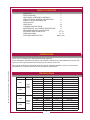
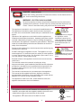
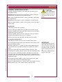
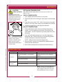
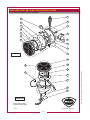
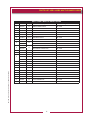
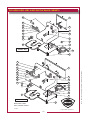
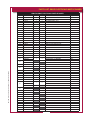
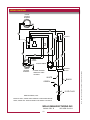
1
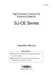
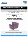
212
WELLS MANUFACTURING
10 Sunnen Dr., St. Louis, MO 63143
telephone: 314-678-6314
fax: 314-781-2714
www.wellsbloomfield.com
OWNERS MANUAL
WAFFLE
BAKER
MODELS
WB1, WB1E
WB2, WB2E
Model WB1E
Includes
INSTALLATION
USE & CARE
EXPLODED VIEW
PARTS LIST
WIRING DIAGRAM
Model WB2E
IMPORTANT: DO NOT DISCARD THIS MANUAL
This manual is considered to be part of the appliance and is to be given to the OWNER or
MANAGER of the restaurant, or to the person responsible for TRAINING OPERATORS of
this appliance. Additional manuals are available from your WELLS DEALER.
THIS MANUAL MUST BE READ AND UNDERSTOOD BY ALL PERSONS USING OR
INSTALLING THIS APPLIANCE. Contact your WELLS DEALER if you have any
questions concerning installation, operation or maintenance of this equipment.
p/n 2M-37055 Rev. K
M212
131111
LIMITED WARRANTY STATEMENT
Unless otherwise specified, all commercial cooking
equipment manufactured by WELLS MANUFACTURING is
warranted against defects in materials and workmanship
for a period of one year from the date of original installation
or 18 months from the date of shipment from our factory,
whichever comes first, and is for the benefit of the original
purchaser only.
THIS WARRANTY IS THE COMPLETE AND ONLY
WARRANTY, EXPRESSED OR IMPLIED IN LAW OR IN
FACT, INCLUDING BUT NOT LIMITED TO, WARRANTIES OF MERCHANTABILITY OR FITNESS FOR ANY
PARTICULAR PURPOSE, AND/OR FOR DIRECT,
INDIRECT OR CONSEQUENTIAL DAMAGES IN
CONNECTION WITH WELLS BLOOMFIELD PRODUCTS.
This warranty is void if it is determined that, upon inspection by an authorized service agency, the equipment has
been modified, misused, misapplied, improperly installed,
or damaged in transit or by fire, flood or act of God. It also
does not apply if the serial nameplate has been removed,
or if service is performed by unauthorized personnel. The
prices charged by Wells Manufacturing for its products are
based upon the limitations in this warranty. Seller’s obligation under this warranty is limited to the repair of defects
without charge by a Wells Manufacturing factory authorized
service agency or one of its sub-service agencies. This service will be provided on customer’s premises for non-portable models. Portable models (a device with a cord and
plug) must be taken or shipped to the closest authorized
service agency, transportation charges prepaid, for service.
In addition to restrictions contained in this warranty, specific
limitations are shown in the Service Policy and Procedure
Guide. Wells Manufacturing authorized service agencies
are located in principal cities. This warranty is valid in the
United States and Canada and void elsewhere. Please
consult your classified telephone directory, your foodservice
equipment dealer or contact:
Wells Manufacturing
10 Sunnen Dr., St. Louis MO 63143 USA
phone (314) 678-6314 or fax (314) 781-2714
for information and other details concerning warranty.
SERVICE POLICY AND PROCEDURE GUIDE and ADDITIONAL WARRANTY EXCLUSIONS
1. Resetting of safety thermostats, circuit breakers, over
load protectors, and/or fuse replacements are not
covered by this warranty unless warranted conditions are the cause.
2. All problems due to operation at voltages or phase other than specified on equipment nameplates are not covered by this warranty.
Conversion to correct voltage and/or phase must be the customer’s responsibility.
3. All problems due to electrical connections not made in accordance with electrical code requirements and wiring diagrams supplied with the equipment are not covered by this warranty.
1. Replacement of items subject to normal wear, to
include such items as knobs, light bulbs; and, normal maintenance functions including adjustments of
thermostats, adjustment of micro switches and
replacement of fuses and indicating lights are not
covered by warranty.
1. Damage to electrical cords and/or plug due to exposure
to excessive heat are not covered by this warranty.
2. Full use, care, and maintenance instructions supplied
with each machine. Noted maintenance and
preventative maintenance items, such as servicing and cleaning schedules, are customer responsibility. Those
miscellaneous adjustments noted are customer
responsibility. Proper attention to preventative
maintenance and scheduled maintenance procedures will prolong the life of the appliance.
7. Travel mileage is limited to sixty (60) miles from an Authorized Service Agency or one of its sub-service agencies.
1. All labor shall be performed during regular working
hours. Overtime premium will be charged to the buyer.
2. All genuine Wells replacement parts are warranted for
ninety (90) days from date of purchase on non-warranty equipment. This parts warranty is limited only to
replacement of the defective part(s). Any use of nonWells parts completely voids any
genuine warranty.
10. Installation, labor, and job check-outs are not
considered warranty and are thus not covered by this warranty.
11. Charges incurred by delays, waiting time or operating restrictions that hinder the service technician’s ability to perform service are not covered by warranty. This SHIPPING DAMAGE CLAIM PROCEDURE
NOTE: For your protection, please note that equipment
in this shipment was carefully inspected and packaged
by skilled personnel before leaving the factory. Upon
acceptance of this shipment, the transportation company
assumes full responsibility for its safe delivery.
FILE CLAIM FOR DAMAGE IMMEDIATELY:
Regardless of the extent of the damage.
1.
CONCEALED LOSS OR DAMAGE: if damage is
unnoticed until the merchandise is unpacked, notify
the transportation company or carrier immediately, and
file “CONCEALED DAMAGE” claim with them. This should be done within fifteen (15) days from the date the delivery was made to you. Be sure to retain the container for inspection.
IF SHIPMENT ARRIVES DAMAGED:
1.
2.
VISIBLE LOSS OR DAMAGE: Be certain that any
visible loss or damage is noted on the freight bill or
express receipt, and that the note of loss or damage is
signed by the delivery person.
xi
TABLE OF CONTENTS
WARRANTY
xi
SPECIFICATIONS
1
FEATURES & OPERATING CONTROLS
2
PRECAUTIONS & GENERAL INFORMATION
3
AGENCY LISTING INFORMATION
3
INSTALLATION
4
OPERATION
5, 6
CLEANING INSTRUCTIONS
7, 8
MAINTENANCE - SET BAKING TEMPERATURE
9
TROUBLESHOOTING SUGGESTIONS
9
EXPLODED VIEW & PARTS LIST
10 - 15
WIRING DIAGRAM
16 - 19
CUSTOMER SERVICE DATA
Back Cover
INTRODUCTION
Thank You for purchasing this Wells Manufacturing appliance.
Proper installation, professional operation and consistent maintenance of this appliance will ensure that
it gives you the very best performance and a long, economical service life.
M212 2M-37055 Owners Manual for WB-1 and WB-2 Waffle Bakers
This manual contains the information needed to properly install this appliance, and to use and care for
the appliance in a manner which will ensure its optimum performance.
SPECIFICATIONS
MODEL
STYLE
WB1
WB1E
Single
Waffle
Baker
WB1-TM
WB2
WB2E
WB2-TM
Double
Waffle
Baker
VOLTAGE 1ø
WATTS
AMPS
POWER SUPPLY CORD
120V
208V
230V
240V
120V
208/240V
220/240
220 CE
120V
208V
230V
240V
120V
208/240V
220/240
220 CE
900 W
676 W
875 W
900 W
900W
676/900W
900W
946 W
1800 W
1352 W
1725 W
1800 W
1800W
1352/1800W
1800W
1892 W
7.5 A
3.25 A
3.8
3.75 A
7.5
3.3/3.8
3.8
4.3 A
15 A
6.5 A
7.5 A
7.5 A
15
6.5/7.5
7.5
8.6 A
NEMA 5-15P
NEMA 6-15P
CEE 7/VII
NEMA 6-15P
NEMA 5-15P
NEMA 6-15P
CE VII 436U
CEE 7/VII
NEMA 5-20P
NEMA 6-15P
CEE 7/VII
NEMA 6-15P
NEMA 5-20P
NEMA 6-15P
CEE 7/VII
CEE 7/VII
FEATURES & OPERATING CONTROLS
UPPER GRID
(RAISED POSITION)
POWER
SWITCH
NAME
PLATE
UPPER GRID
(LOWERED
POSITION)
POWER
CORD
BACK VIEW
HANDLE
DRIP TRAY
TIMER
TEMPERATURE
CONTROL
LOWER GRID
ADJUSTABLE NON-SLIP FEET
M212 2M-37055 Owners Manual for WB-1 and WB-2 Waffle Bakers
IL2764
Fig. 1 Waffle Baker - Features & Operating Controls (WB2 shown, WB1 similar)
PRECAUTIONS AND GENERAL INFORMATION
DANGER: BURN HAZARD
Contact with cooking grid surface will cause severe burns. Use the handle to lift the
grid. Avoid contact with grid surfaces.
WARNING: ELECTRIC SHOCK HAZARD
All servicing requiring access to non-insulated components must be performed by
qualified service personnel. DO NOT open any access panel that requires the use
of tools. Failure to heed this warning may result in severe electric shock.
CAUTION:
This appliance is intended for use in commercial establishments only.
This appliance is intended to prepare food for human consumption.
No other use is recommended or authorized by the manufacturer or its
agents.
Operators of this appliance must be familiar with the appliance use,
limitations and associated restrictions. Operating instructions must be
read and understood by all persons using or installing this appliance.
Cleanliness of this appliance is essential to good sanitation. Read and
follow all included cleaning instructions and schedules to ensure the
safety of the food product.
Risk of
Damage
DO NOT connect or energize
this appliance until all
installation instructions are
read and followed. Damage
to the appliance will result if
these instructions are not
followed.
Disconnect this appliance from electrical power before performing any
maintenance or servicing.
DO NOT submerge this appliance in water. This appliance is not jet
stream approved. Do not direct water jet or steam jet at this appliance,
or at any control panel or wiring. Do not splash or pour water on, in or
over any controls, control panel or wiring.
CAUTION:
Hot Surface
Exposed surfaces can be hot
to the touch and may cause
burns.
M212 2M-37055 Owners Manual for WB-1 and WB-2 Waffle Bakers
Exposed surfaces of this appliance can be hot to the touch and may
cause burns.
The technical content of this manual, including any wiring
diagrams,schematics, parts breakdown illustrations and/or adjustment
procedures, is intended for use by qualified technical personnel. Any
procedure which requires the use of tools must be performed by a
qualified technician.
This manual is considered to be a permanent part of the appliance.
This manual and all supplied instructions, diagrams, schematics,
parts breakdown illustrations, notices and labels must remain with the
appliance if it is sold or moved to another location.
This appliance is made in the USA. Unless otherwise noted, this
appliance has American sizes on all hardware.
AGENCY LISTING INFORMATION
This appliance conforms to NSF Standard 4 for sanitation only if
installed in accordance with the supplied Installation Instructions and
maintained according to the instructions in this manual.
This appliance is
STD 4
U Listed under UL File E6070 for 120V.
C
®
LISTED
US
E6070
INSTALLATION
CAUTION:
Risk of
Damage
DO NOT connect or energize
this appliance until all
installation instructions are
read and followed. Damage
to the appliance will result
if these instructions are not
followed.
CAUTION:
Electrical
Shock
HazARD
The ground prong of the power
cord is part of a system
designed to protect you from
electric shock in the event of
internal damage to the
appliance.
NEVER CUT OFF THE
GROUND PRONG
(large round prong).
NEVER TWIST A PRONG TO
FIT AN EXISTING
RECEPTACLE.
Contact a licensed electrician
to install an electrical
receptacle appropriate to
the voltage and amperage
requirements of the
waffle baker.
IMPORTANT:
Damage due to being
connected to the wrong voltage
or phase is NOT covered by
warranty.
UNPACKING & INSPECTION
Carefully remove the appliance from the carton. Remove all protective
plastic film, packing materials and accessories from the appliance
before connecting performing any installation procedure.
Carefully read all instructions in this manual and the Installation
Instruction Sheet packed with the appliance before starting any
installation.
Read and understand all labels and diagrams attached to the
appliance.
Carefully account for all components and accessories before discarding
packing materials. Store all accessories in a convenient place for later
use.
COMPONENTS
1 or 2 ea. DRIP TRAY(S)
1 or 2 ea. HANDLE(S)
4 ea. ADJUSTABLE FEET
SETUP
Lightly lubricate threaded boss of upper grid using vegetable oil.
Thread handle onto boss, making sure that they are fully seated.
Handles are not removable once installed.
Setup the appliance only on a firm, level, non-combustible surface.
Verify local codes for requirements. Concrete, tile, terrazzo or metal
surfaces are recommended.
Install the provided adjustable feet, one on each corner of the
appliance, in the holes provided. Verify that the unit sits firmly on ALL
FOUR FEET. Adjust as required to level the appliance. All four feet
must be adjusted to firmly contact the countertop in order to prevent
tipping.
ELECTRICAL INSTALLATION
Refer to the nameplate. Verify the electrical service power. Voltage
and phase must match the nameplate specifications. Connecting the
waffle baker to the wrong voltage can severely damage the unit or
cause noticeably decreased performance.
IMPORTANT: Damage due to being connected to the wrong voltage is
NOT covered by warranty.
SEASONING THE GRIDS
Lightly spray commercial waffle baker spray on both upper and lower
grid.
Carefully close the upper grid. Turn the power switch on, then allow the
waffle baker to pre-heat for at least 20 minutes.
Using the handle, lift the upper grid and lightly re-coat both upper and
lower grid. Lower the upper grid.
The appliance is now ready for use.
M212 2M-37055 Owners Manual for WB-1 and WB-2 Waffle Bakers
NOTE: DO NOT discard
the carton or other packing
materials until you have
inspected the appliance for
hidden damage and tested it
for proper operation.
Refer to SHIPPING DAMAGE
CLAIM PROCEDURE on the
inside front cover of this
manual.
OPERATION
GENERAL OPERATIONAL NOTES
Carefully read the description of the waffle baker operation on the
specification sheet.
DO NOT attempt to perform any maintenance or service unless the
waffle baker is disconnected from electrical power.
DO unplug the waffle baker before cleaning, servicing or performing
any maintenance.
CAUTION:
HOT SURFACE
Exposed surfaces can be hot
to the touch and may cause
burns.
DO NOT use sharp objects or metal implements to clean the grids.
DO use a plastic spatula or plastic scouring pad to remove burned-on
food product.
OPERATION
Turn power switch to the on position.
With the upper grid closed, allow to preheat for at least 20 minutes.
Using the handle, lift the upper grid. Pour desired amount of Belgian
Waffle Batter onto the lower grid.
Using the handle, carefully close the upper grid. Turn timer knob to
desired setting (approximately 2-1/2 to 3 minutes).
When the bell rings, raise the upper grid and remove the waffle.
Cooking Recommendations:
Keep the grids closed when not in use to maintain temperature.
M212 2M-37055 Owners Manual for WB-1 and WB-2 Waffle Bakers
Use a soft bristle brush to lightly brush and clean cooking debris from
the grids between waffles.
Reseason grids every 3 - 4 waffles to guard against waffles sticking.
This interval may be extended by adding oil or butter to the waffle
batter.
Always use fresh batter that contains sufficient shortening. Add
shortening as necessary, and do not store batter for extended periods.
Ensure a perfect, great-tasting waffle by cleaning and re-seasoning
frequently. After every third waffle, and anytime the waffle baker has
been left idle for over one-half hour, lightly spray grids with commercial
waffle baker spray.
Never apply beeswax, paraffin or other such materials to the grids.
Use only a quality commercial waffle baker spray.
Never use sharp implements (i.e. knives, forks, metal tongs) to remove
waffles from the grid. Use a plastic spatula or plastic tongs.
IMPORTANT:
The timer bell will ring at the
end of the cooking time. The
timer bell is only a signal that
the waffle is done. It does not
turn the heating element on or
off.
Remove the waffle promptly
when the bell rings.
OPERATION (ELECTRONIC UNITS) WB1E & WB2E
CAUTION:
HOT SURFACE
Exposed surfaces can be hot
to the touch and may cause
burns.
MAKING WAFFLES
Turn the unit on and allow to pre-heat for 15 minutes with the grids
closed. Once the baker has reached proper temperature you can
proceed as follows:
1. Brush on releasing agent, if needed
2. Lift the lid, pour in mix and close.
3. Start timer by pressing the start/stop pad.
4. When timer beeps, depress the start/ stop pad.
5. Remove waffle.
6. For next waffle repeat steps 1 through 5.
Setting the Time:
If necessary, the factory pre-set timer can be adjusted to satisfy
individual preferences.
+
-
The timer bell will ring at the
end of the cooking time. The
timer bell is only a signal that
the waffle is done. It does not
turn the heating element on or
off.
Remove the waffle promptly
when the bell rings.
To decrease time, depress and hold the “down” button.
The “start/stop” button can now be used to decrease
baking time.
SETTING THE TEMPERATURE
If necessary, the factory pre-set temperature can be changed: To
view the temperature, depress and hold “TEMP” button and press
“START/STOP” button. Hold both buttons for 3 seconds for the preset temperature to be displayed.
To increase the temperature press “+” button; to decrease press “-“
button.
To lock the temperature press the “START/STOP” button.
Changing the displayed temperature from “F” (Fahrenheit) to
“C” (Celsius) Hold “TEMP” button and turn “OFF” and then “ON” the lighted
switch on the front panel. To change back from “C” to “F”, repeat
the same procedure. Setting the temperature is available in both
modes “F” and “C”.
M212 2M-37055 Owners Manual for WB-1 and WB-2 Waffle Bakers
IMPORTANT:
To increase time, depress and hold the “up” button. The
start/ stop button can now be used to increase baking
time.
CLEANING INSTRUCTIONS
PREPARATION
CAUTION:
Burn Hazard
Unplug appliance from electric power
Allow appliance to cool completely.
Allow waffle baker to cool
completely before cleaning.
FREQUENCY
Daily
TOOLS
Plastic Scouring Pad, Soft-Bristled Fiber Brush
Mild Detergent, Non-Abrasive Cleanser
Clean Soft Cloth / Sponge
CLEANING
1. Allow the waffle baker to cool to room temperature.
2. Clean grids by using a soft-bristle brush to remove any
remaining cooking residue.
IMPORTANT:
DO NOT spill or pour water
into controls.
DO NOT submerge appliance
in water. This will damage
internal components. Damage
to internal components from
water is NOT covered by
warranty.
DO NOT use steel wool or
3. Clean the outside of the Waffle Baker by wiping it with a soft, metal scouring pads to clean
clean cloth dampened with warm water and a mild detergent. appliance or drip tray.
NEVER USE AN ABRASIVE CLEANSER.
Good sanitation is vital to
4. Rinse by wiping with a soft, clean cloth dampened with clean the quality of the final food
product. Be sure to clean in
water. Allow to air dry.
5. Re-season the grids after cleaning by spraying with a
commercial waffle baker spray.
M212 2M-37055 Owners Manual for WB-1 and WB-2 Waffle Bakers
Procedure complete
all corners and crevices where
grease and other cooking
debris can accumulate.
CLEANING INSTRUCTIONS (continued)
PREPARATION
CHEMICAL
BURN HAZARD
Waffle baker cleaner may
cause serious burns on
contact.
Wear protective clothing and
safety glasses when using
waffle baker cleaner.
Carefully read and follow
directions and warnings on
the label.
CAUTION:
ELECTRIC
SHOCK
HAZARD
DO NOT submerge the waffle
baker in water. If internal
components become wet, the
operator may suffer electrical
shock, and the waffle baker
will be damaged.
Use this procedure to
clean any black residue
(carbonization) remaining
on the grids after the daily
cleaning. Grids must be
cleaned to remove the black
residue, then re-seasoned, to
ensure optimal performance.
Unplug appliance from electric power
Allow appliance to cool completely.
FREQUENCY
As needed
TOOLS
Commercial Carbon Cleaner
1” Bristle Brush, Stiff Fiber Brush
Clean Soft Cloth / Sponge
REMOVE CARBONIZATION FROM GRIDS
1. Allow the waffle baker to cool to room temperature.
2. Liberally apply a commercial carbon cleaning solution to
the grids with a new 1” bristle brush. Be extremely careful
when applying carbon cleaning solution to the grid surfaces.
DO NOT spill any carbon cleaning solution or other caustic
cleaning product on yourself or adjacent work surfaces.
IMPORTANT: Read and follow all manufacturer’s
instructions when using commercial carbon cleaners.
Carbon cleaner can be hazardous. It is the operator’s
responsibility to use the product safely, in the manner
directed by the carbon cleaner manufacturer.
3. Close the upper grid and allow the appliance to stand for
several hours, or overnight, depending upon the extent of the carbonization.
4. Thoroughly remove the carbon cleaning solution and black
residue using a fiber brush. Wipe down the grid surfaces
carefully and thoroughly with water so that no carbon
cleaning solution remains on the grids.
IMPORTANT: Make certain water and cleaner are not
allowed to get into internal parts. The waffle baker will be
damaged if internal components are allowed to get wet.
5. Clean the outside of the Waffle Baker by wiping it with a soft, clean cloth dampened with warm water and a mild detergent. NEVER USE AN ABRASIVE CLEANSER.
6. Rinse by wiping with a soft, clean cloth dampened with clean water. Allow to air dry.
7. Re-season the grids after cleaning by spraying with a
commercial waffle baker spray.
Procedure complete
M212 2M-37055 Owners Manual for WB-1 and WB-2 Waffle Bakers
CAUTION:
MAINTENANCE
CAUTION:
SET BAKING TEMPERATURE
Wells WB1 and WB2 waffle bakers are factory set for 390ºF ±5ºF
(200ºC ± 3ºC).
Burn Hazard
Exposed surfaces of the
waffle baker may be hot to the
touch and can cause burns.
Waffle baker grids are very
hot and will cause serious
burns on contact.
CHECK TEMPERATURE
1. Use a digital thermometer with an oven probe.
2. Place the probe on the lower grid, then gently close the upper
grid.
3. Press the power switch “ON”. Wait 15 minutes for the waffle
baker to come up to heat, and for the temperature to stabilize.
4. Read the temperature on the digital thermometer.
ADJUST TEMPERATURE
1. Each waffle baker section has an individual temperature
control. Pry round hole plug from back of that side of the
waffle baker. DO NOT disconnect grounding tether from the
hole plug.
M212 2M-37055 Owners Manual for WB-1 and WB-2 Waffle Bakers
Proper temperature for baking
waffles is 390ºF (200ºC).
Variations in altitude and/or
batter mix may require a
slightly different temperature
for best results.
2. Use a thin flat-blade screwdriver to turn the temperature
adjustment dial. Rotate clockwise to increase temperature; counter-clockwise to decrease temperature.
NOTE: Make small incremental changes only.
3. Allow at least 3 minutes for temperature to stabilize before
making another adjustment.
4. When desired temperature is reached reinstall hole plug.
TROUBLESHOOTING
SYMPTOM
Will not heat
Does not maintain
temperature
POSSIBLE CAUSE
SUGGESTED REMEDY
Power cord not plugged in, or circuit breaker
tripped
Establish main power. Be sure appliance is
plugged in
Power switch off
Turn power switch on
Internal component damage
Contact an authorized Wells Service Agency for
repairs.
Excessive carbonization of grids
Decarbonize grids
Internal component damage
Contact an authorized Wells Service Agency for
repairs.
NOTE: There are no user serviceable components in the cabinet or cooking grids. In all
cases of damage or malfunction, contact your
Authorized Wells Service Agency for repairs.
EXPLODED VIEW: WB1 & WB2 WAFFLE BAKER GRIDS
WAFFLE BAKER GRIDS for WB1 and WB2
1
22
2
21
3
20
12
11
4
10
5
19
6
7
8
UPPER GRID
9
10
18
17
13
14
15
16
LOWER GRID
Model: WB1 & WB2
WAFFLE BAKER GRIDS
PL212
IL1776 Rev. B 6/23/11
10
M212 2M-37055 Owners Manual for WB-1 and WB-2 Waffle Bakers
12
PARTS LIST: WB1 & WB2 WAFFLE BAKER GRIDS
WB-1 & WB-2 WAFFLE BAKER GRIDS
Fig No
Qty
Description
Application
2R-30335
1/2
HANDLE SPRING PLATED
WB1 / WB2
2
2F-30327
1/2
CAST TOP MACHINED & POLISHED
WB1 / WB2
3
2P-38628
1/2
PLUG HOLE 5/8 DIA.
WB1 / WB2
4
2F-30322
1/2
HINGE, WB1 & WB2
WB1 / WB2
5
2V-30328
1/2
PLUG HINGE MACH & PLT
WB1 / WB2
6
1O-34573
1 / 2 FT
SLEEVING GLASS # 5
WB1 / WB2
7
2I-30284
1 / 2 FT
GASKET TUBING RUBBER
WB1 / WB2
GRID ASSY TOP 120V STD
WB1 / WB2
GRID ASSY TOP 208/240V STD
WB1 / WB2
GRID ASSY BOT 120V STD
WB1 / WB2
8
9
WS-58881
WS-58880
DD-61743
DD-61742
1/2
1/2
GRID ASSY BOT 208/240V STD
WB1 / WB2
10
2I-30337
2/4
GASKET GRID TOP & BOT
WB1 / WB2
11
2K-307280
2/4
BUSHING ELEM TERM INSULATOR
WB1 / WB2
WS-507277
2/4
ELEM 120V 450W
WB1 / WB2
2N-Z14467
1/2
ELEMENT 450W, 220V
WB1-TM-220CE, WB2-TM-220CE
12
M212 2M-37055 Owners Manual for WB-1 and WB-2 Waffle Bakers
Part No
1
2N-Z14468
1/2
ELEMENT 500W, 220V
WB1-TM-220CE, WB2-TM-220CE
13
B8-30445
1/2
PLATE CLAMPING BOTTOM
WB1 / WB2
14
2F-30326
1/2
CAST BOTTOM MACHINED & POLISHED
WB1 / WB2
15
2C-38627
2/4
NUT 8-32 MS ACORN CAP
WB1 / WB2
16
2I-30338
1/2
GASKET BOT CASTING
WB1 / WB2
17
WS-507279
1/2
PROBE TEMP WB-SERIES
WB1 / WB2
18
2F-307657
1/2
GRID BOT MACHASRECD
WB1 / WB2
19
2F-38917
1/2
GRID TOP MACHASRECD
WB1 / WB2
20
2G-30430
1/2
PAD INSULATION TOP
WB1 / WB2
21
B8-30431
1/2
PLATE CLAMPING TOP
WB1 / WB2
22
2F-30329
1/2
CAST COND MACH&PLT REC 33
WB1 / WB2
11
EXPLODED VIEW : WB1 & WB2 WAFFLE BAKER CABINETS
19
1
17
16
2
15
14
3
13
4
12
5
11
6
10
7
8
CABINET WB-1
22
9
4
18
17
1
15
14
2
16
19
21
5
3
12
6
11
22
7
8
10
21
CABINET WB-2
9
Model: WB1 & WB2
WAFFLE BAKER CABINET
PL212
IL1777 Rev. C 6/17/11
12
M212 2M-37055 Owners Manual for WB-1 and WB-2 Waffle Bakers
13
PARTS LIST: WB1 & WB2 WAFFLE BAKER CABINETS
WB-1 & WB-2 WAFFLE BAKER CABINET
Fig No
1
2
3
4
5
Part No
1
2E-35127
1
2E-30330
2E-304030
2I-30338
7
8
9
10
M212 2M-37055 Owners Manual for WB-1 and WB-2 Waffle Bakers
11
12
13
14
15
16
17
18
19
20
21
1
1
2A-30333
WS-60332
B8-35552
1M-35547
B8-31856
2E-32101
2
1
1
1
2
2
1
1
4
1
2
2
4
2
1
2
1
1
2
1
1
2
2
2
2
2
2
2
2
1
1
2E-Z13852
22
B8-307352
2E-Z15407
B8-307354
B8-307351
B8-WL0295
B8-307357
B8-307353
PANEL, REAR
ASM-PANEL WB-2-WHNT
ASSY HOLE PLUG
SHELL ASSY SINGLE BAKER
SHELL ASSY DOUBLE BAKERS
SHELL ASSY WB-2 W/O TIMER
SHELL AY WB2 W/O TIMER
SWITCH ROCK PLAS BEZEL
SWITCH ON OFF TOGGLE
SWTICH ROCK (‘I/O’ MARKING)
GASKET BOT CASTING
STRAIN RELIEF 90 DEG
1
1
1
1
Application
REAR PANEL
1
2K-Y3240
2K-Z15511
2T-307647
B8-307482
2A-45728
B8-38629
WS-50446
2R-30447
PS-WL0239
2V-30328
2C-30222
2F-30322
2F-30329
Description
WB1 WB2
B8-Z12400
B8-Z12401
B8-Z13851
B8-Z15519
B8-41064
B8-33653
B8-31551
B8-40621
B8-Z15518
2K-31217
6
Qty
STRAIN RELEIF SR 17-2
STRAIN REL-LIQ TIGHT.87
CONTROL TEMP W/RTV
BRACKET CONTROL MOUNTING
FOOT RUBBER LLW LLF
DRIP TRAY WAFFLE BAKER
TIMER WAFFLE BAKER W/KNOB
KNOB BELL TIMER ROHS
KIT, TIMER BELL BAKERS w/KNOB
PLUG HINGE
RETAINER E-RING .179 ID
HINGE AS RECD WB1 & 2
CAST COND MACH&PLT
1
WB2WHNT, before serial no:WB2L0612A001
WB2WHNT, after serial no:WB2L0612A001
WB2WHNT, before serial no:WB2L0612A001
WB2WHNT, after serial no:WB2L0612A001
WB2E-230V
mfg After 3/2012
mfg Before 3/2012
WB2WHNT, before serial no:WB2L0612A001
WB2WHNT, after serial no:WB2L0612A001
PIN HINGE BAKER
HINGE KIT WB
CONDUIT SOLID LS
CONDUIT SOLID WB
PANEL BOT WB2 ROHS
HSG FLEX COND MACH
CPRD SET, 12-3 SKTP 5-20P 20 AMP
1
WB-1
WB-2
WB2WHNT, before serial no:WB2L0612A001
WB2WHNT, after serial no:WB2L0612A001
CORD SET WB2 120V
CORD SET ASY L5-20P
CORD SET WB2 208/240V
CORD SET WB2 208/240V 6FT
ASSEMBLY, CORDSET
CORD SET WB1 120V
CORD SET WB1 240V
13
WB2WH-120V
WB2WHNT, before serial no:WB2L0612A001
WB2-120
WB2WHNT, after serial no:WB2L0612A001
WB2, WB2SS
WB2CD
WB2-TM-220CE, WB2-230
WB1-120
WB1-240
EXPLODED VIEW : WB1E ELECTRONIC WAFFLE BAKER
1
2
3
4
5
6
7
8
9
24
25
10
11
26
12
13
14
15
27
16
28
10
30
23
13
31
22
29
32
M212 2M-37055 Owners Manual for WB-1 and WB-2 Waffle Bakers
14
17
7
10
33
18
34
26
19
20
21
Model: WB1E,
Electronic Waffle Baker
SK2679
14
Rev. -
8/16/13
PARTS LIST: WB1E ELECTRONIC WAFFLE BAKER
WB1E & WB2E, ELECTRONIC WAFFLE BAKER
Fig No
WB1E
WB2E
Description
1
2
3
4
5
6
B8-35552
2F-30329
2C-30222
2F-30322
2V-30328
2P-38628
1
1
1
1
1
1
2
2
2
2
2
2
CONDUIT SOLID
CAST COND MACH&PLT REC 33
RETAINER E RING .179 ID
HINGE AS RECD WB-1 -2
PLUG HINGE MACH&PLT
PLUG HOLE 5/8 DIA NI
7
2C-31053
9
14
NUT 8-32 KEPS MS NICKEL
8
9
10
11
12
13
14
15
16
17
18
19
20
21
2F-30327
2R-30335
2C-31715
B8-Z16245
2K-307280
2N-307811UL
2I-30337
2F-38917
2F-307657
B8-Z16246
2F-30326
2C-32242
2C-38627
2I-30338
2E-35127
2E-304030
2M-Z16571
2M-Z16572
B8-38629
B8-Z16411
B8-Z17180
2C-33935
2A-30333
2K-08-07-0004
B8-Z16898
2K-Z1971
2E-Z5375
2E-05-07-0351
2E-05-07-0350
2E-Z2974
B8-Z16410
B8-Z17179
2A-45728
2E-34538
2E-35539
2E-35540
2E-72920
D5-MDW088
2J-Z16743
2K-31217
2K-Y3240
2K-70648
2K-76118
1
1
13
1
4
2
2
1
1
1
1
6
2
1
2
2
26
2
8
4
4
2
2
2
2
12
4
2
1
2
CAST TOP MACHINED & POLIS
HANDLE SPRING PLATED
SCREW 8-32X5/16 PH RD HD
PLATE, ELEMENT CLAMP TOP
BUSHING ELEM TERM INSULAT
ELEM 120V 450W + 2 TERM S
GASKET GRID TOP&BOT
GRID TOP CAST AND MACH AS
GRID BOTTOM CAST/MACHINED
PLATE,ELEMENT CLAMP BOTTM
CAST BOTTOM MACHINED &POL
WASHER ZI LRG PATTERN #10
NUT 8-32 MS ACORN CAP NI
GASKET BOT CASTING
SWITCH ROCK PLAS BEZEL W/
SWITCH ROCK (‘I/O’ MARKING
OVERLAY, TIME/TEMP-WB2C
OVERLAY, TIME/TEMP WB1C
TRAY DRIP WAFFLE BAKER
PANEL-REAR-WB1E
PANEL, REAR WB2E
SCREW 6ABX5/16 PH PAN SMS
PIN HINGE BAKER
SPACER ROUND NYLON
TIMER/TEMP CONTRL WB1C/2C
SPACER .257X.75X.25 NYLON
TERMINAL BLOCK-3 POLE
TRANSFORMER 115/10V 6VA
TRANSFORMER 230V/10V 6VA
TRANSFORMER 230V/10V CE
PANEL-BTM WB1E
PANEL-BTM WB2E
FOOT RUBBER LLW LLF
CORD SET 125V NEMA 5-20P
CORD SET 120V, 15A 16GA 4FT
CORD SET 6-15P 16/3W 4FT
CORD & CAP EURO 3COND (CE
CORDSET ASSY., CEE7/VII
PROBE-TEMP RTD
STRAIN RELIEF 90°DEG
BUSHING ST 17-2
STRAIN RELIEF SMALL
STRAIN RELIEF STR
22
23
24
25
M212 2M-37055 Owners Manual for WB-1 and WB-2 Waffle Bakers
Part Number
26
27
28
29
30
31
32
33
34
NI
NI
NI
NI
NI
NI
NI
NI
NI
NI
1
1
1
1
2
7
1
6
1
6
1
1
8
2
12
2
12
1
1
2
1
1
2
4
1
1
1
1
1
1
4
1
1
1
2
1
1
1
15
Application
120V, 240V
230V
120V
240V
230V
120V
120V
240V
WB1E-230V
WB2E-230V
WB1E-230V
WB2E-230V
WIRING DIAGRAM
UPPER
HEATING
ELEMENT
7
H
D
j
E8
RTD
E1
E3
10VAC
E4
SWITCH
E7
E2
E
D
E
C
A
B
TEMP.
PROBE
7
LOWER
HEATING
ELEMENT
C
TRANSFORMER
TERMINAL
BLOCK
**LOWER GROUND
WIRE NOT USED
ON WB1E
WHITE
GREEN
BLACK
5-15P-PLUG
WIRE DIAGRAM, 120V
MODELS: WB1C, SINGLE WAFFLE BAKER- CANTILEVER DESIGN
WB1E, SINGLE STD. WAFFLE BAKER- ELECTRONIC CONTROLS
WELLS MANUFACTURING INC.
SK2634 REV. B
16
DR: WEB 09/16/13
M212 2M-37055 Owners Manual for WB-1 and WB-2 Waffle Bakers
J
WIRING DIAGRAM
UPPER
HEATING
ELEMENT
7
H
J
D
COUPLER
E1
E8
RTD
E3
10VAC
E4
SWITCH
E7
E2
E
K
D
E
J
A
B
TEMP.
PROBE
L
208/240V
7 ** TRANSFORMER
M212 2M-37055 Owners Manual for WB-1 and WB-2 Waffle Bakers
LOWER
HEATING
ELEMENT
TERMINAL
BLOCK
**LOWER GROUND
WIRE NOT
USED ON WB1E
WHITE
VOLTS NOMINAL AMPS
WB-1
208
3.3
220
3.6
240
3.8
GREEN
BLACK
POWER CORD
WIRE DIAGRAM, 208/240V
220/240V
MODELS: WB1C, SINGLE WAFFLE BAKER- CANTILEVER DESIGN - ELECTRONIC CONTROLS - 208/240V, 220/240V
WB1E, SINGLE STD. WAFFLE BAKER- ELECTRONIC CONTROLS - 208/240V, 220/240V
SK2695
17
10/16/13 REV (-)
B
C
C
H
J
J
E2
E1
D
LOWER
HEATING
ELEMENT
UPPER
HEATING
ELEMENT
7
18
E7
**LOWER GROUND
WIRE NOT USED
ON WB2E
TRANSFORMER
E8
RTD
7
TEMP.
PROBE
E3
10VAC
E4
E
E
D
J
M212 2M-37055 Owners Manual for WB-1 and WB-2 Waffle Bakers
J
LOWER
HEATING
ELEMENT
E2
E1
UPPER
HEATING
ELEMENT
7
H
E8
E7
E
D
C
TERMINAL
BLOCK
E
WHITE
B
SK2639 REV. B
BLACK
5-15P-PLUG
D
DR: WEB 09/16/13
B
A
SWITCH
WELLS MANUFACTURING INC.
GREEN
**LOWER GROUND
WIRE NOT USED
ON WB2E
TRANSFORMER
TEMP.
PROBE
C
E3
10VAC
E4
7
A
RTD
WIRE DIAGRAM
WB2C-120V WELLS TWIN WAFFLE BAKER CANTILEVER.
WB2E-120V WELLS TWIN STD WAFFLE BAKER W/
ELECTRONIC CONTROLS
SWITCH
A
WIRING DIAGRAM
19
E
5
E
L
LOWER
HEATING
ELEMENT
E2
E1
D
E8
E7
**LOWER GROUND
WIRE NOT
USED ON WB2E
TEMP.
PROBE
TRANSFORMER
7 **
E3
10VAC
E4
E
E
J
J
E1
E2
LOWER
HEATING
ELEMENT
K
COUPLER
6.5
7.2
7.5
208
220
240
H
E8
E7
E
D
E
SK2696 REV. B
POWER
CORD
GREEN
L
TERMINAL
BLOCK
WHITE
B
B
D
E
5
E
1
12
D
BLACK
220/240V
TRANSFORMER
(SIDE VIEW)
7
L
DR: WEB 10/16/13
A
SWITCH
WELLS MANUFACTURING INC.
**LOWER GROUND
WIRE NOT
USED ON WB2E
TEMP.
PROBE
TRANSFORMER
7 **
E3
10VAC
E4
7
VOLTS NOMINAL AMPS
WB-2
D
WIRE DIAGRAM
WB2C WELLS TWIN WAFFLE BAKER CANTILEVER - ELECTRONIC CONTROLS - 208/240V, 220/240V
WB2E WELLS TWIN STD WAFFLE BAKER - ELECTRONIC CONTROLS - 208/240V, 220/240V
220/240V
TRANSFORMER
(SIDE VIEW)
1
K
COUPLER
UPPER
HEATING
ELEMENT
RTD
12
D
J
J
UPPER
HEATING
ELEMENT
A
RTD
7
L
SWITCH
H
A
C
7
B
D
B
A
C
A
B
D
M212 2M-37055 Owners Manual for WB-1 and WB-2 Waffle Bakers
WIRING DIAGRAM
M212 2M-37055 Owners Manual for WB-1 and WB-2 Waffle Bakers
WIRING DIAGRAM
20
M212 2M-37055 Owners Manual for WB-1 and WB-2 Waffle Bakers
WIRING DIAGRAM
21
WELLS MANUFACTURING
10 Sunnen Dr., St. Louis, MO 63143
telephone: 314-678-6314
fax: 314-781-2714
www.wellsbloomfield.com