1
Windward Passage Operating Manual
WPOperatingManual
-i-
Revised: August 12, 2009
Contents
I.
Stowage Compartment Layout and Contents ........................................................ 1
A. Stowage Documentation ....................................................................................... 1
B. Main Salon Storage Layout.................................................................................. 2
C. Forward and Aft Cabins Layout ......................................................................... 3
D. Cockpit Stowage Layout....................................................................................... 4
II. Safety Information .................................................................................................... 5
A. Personal.................................................................................................................. 5
1. Life Preservers................................................................................................... 5
2. Harnesses, Tethers and Jack Lines.................................................................. 5
3. Emergency Signaling Devices .......................................................................... 5
(a)
Flares .......................................................................................................... 5
(b)
Distress flag................................................................................................ 5
(c)
Signal horn................................................................................................. 5
(d)
Fog bell ....................................................................................................... 5
(e)
EPIRB ........................................................................................................ 5
(f)
VHF Radio ................................................................................................. 6
(g)
SSB Radio .................................................................................................. 6
4. Life Raft ............................................................................................................. 6
5. Person Overboard Life Sling ........................................................................... 6
6. Person Overboard Pole..................................................................................... 6
B. Disaster Control .................................................................................................... 7
1. Fire Control ....................................................................................................... 7
2. Flooding Control ............................................................................................... 7
3. Through-hull Fittings ....................................................................................... 8
4. Emergency Tiller............................................................................................... 8
5. Storm Jib............................................................................................................ 8
6. Storm Trysail..................................................................................................... 9
7. Sea Anchor......................................................................................................... 9
8. Top Climber..................................................................................................... 10
III. System Operations .................................................................................................. 11
A. Auxiliary Engine ................................................................................................. 11
1. Maintenance Checks ....................................................................................... 11
(a)
Fresh Water Level in Engine ................................................................. 11
(b)
Engine Oil Level ...................................................................................... 11
(c)
Belt Tension ............................................................................................. 11
(d)
Transmission Fluid Level ....................................................................... 11
(e)
Engine Room ........................................................................................... 12
2. Engine Operation ............................................................................................ 12
(a)
General ..................................................................................................... 12
(b)
Starting the Engine ................................................................................. 12
WPOperatingManual
- ii -
Revised: August 12, 2009
(c)
Stopping the Engine ................................................................................ 12
(d)
Engaging the transmission ..................................................................... 13
(e)
Engine speed ............................................................................................ 13
(f)
Fuel Supply .............................................................................................. 13
3. Potential Problems .......................................................................................... 14
(a)
Gear Cable Failure.................................................................................. 14
(b)
Throttle Cable Failure ............................................................................ 14
B. Autopilot .............................................................................................................. 14
1. Basic Operation ............................................................................................... 14
2. Controls............................................................................................................ 14
3. Cautions ........................................................................................................... 15
C. Anchoring ............................................................................................................ 15
1. Anchor and Windlass...................................................................................... 15
2. Anchor Wash System...................................................................................... 15
D. Dinghy and Engine.............................................................................................. 16
1. Dinghy Storage ................................................................................................ 16
2. Inflation............................................................................................................ 16
3. Deflation ........................................................................................................... 16
4. Operation ......................................................................................................... 16
5. Engine Operation ............................................................................................ 17
6. Engine Storage................................................................................................. 17
E. Housekeeping....................................................................................................... 17
1. Fresh Water System........................................................................................ 17
2. Propane System ............................................................................................... 18
3. Refrigerator ..................................................................................................... 19
(a)
General ......................................................................................................... 19
(b)
Sea Frost Freezer Plate System.................................................................. 19
(c)
Evaporator System...................................................................................... 19
(d)
Refrigerator Compartment ........................................................................ 19
4. Lectrasan Unit and Head ............................................................................... 20
F. Electrical .............................................................................................................. 20
1. Electrical Panel................................................................................................ 20
2. Shore Power..................................................................................................... 21
3. Battery Charger/Inverter ............................................................................... 21
4. Battery System................................................................................................. 22
5. Wind Generator .............................................................................................. 22
6. Tow Behind Ferris Generator........................................................................ 22
7. Running Lights ................................................................................................ 23
G.
Electronics........................................................................................................ 23
1. Cockpit Instrument Panel .............................................................................. 23
2. VHF Radio ....................................................................................................... 24
3. SSB Radio ........................................................................................................ 26
4. Radar/Chart Plotter........................................................................................ 26
H.
Sail Handling ................................................................................................... 27
WPOperatingManual
- iii -
Revised: August 12, 2009
1. Mainsail Reefing System................................................................................. 27
2. Jib Reefing System .......................................................................................... 27
3. Spinnaker System............................................................................................ 28
4. Whisker Pole Operation ................................................................................. 28
IV. Specifications and Equipment Data ...................................................................... 29
A. Boat Specifications .............................................................................................. 29
B. Electrical Equipment .......................................................................................... 29
1. DC Power Wiring............................................................................................ 30
2. DC Wiring Details ........................................................................................... 31
3. DC wiring at Main Panel................................................................................ 32
5. Wiring Diagram for Wind and Tow-Behind Generators............................ 34
C. Spars, Running Rigging and Sails ..................................................................... 35
1. Mast .................................................................................................................. 35
2. Standing Rigging ............................................................................................. 36
3. Running Rigging ............................................................................................. 37
4. Sails................................................................................................................... 38
WPOperatingManual
- iv -
Revised: August 12, 2009
I. Stowage Compartment Layout and Contents
A. Stowage Documentation
A complete listing of all of the items except provisions stowed on Windward Passage may be found in
the Ship’s Operation Binder and as an Excel spreadsheet on the ship’s computer. The printed version is
sorted three ways: by item, by category and by location. A listing of the provisions and their location is
developed for each passage and is maintained in the Ship’s Operation Binder.
WPOperatingManual
Page - 1 -
Revised: August 12, 2009
B. Main Salon Storage Layout
WPOperatingManual
Page - 2 -
Revised: August 12, 2009
C. Forward and Aft Cabins Layout
WPOperatingManual
Page - 3 -
Revised: August 12, 2009
D. Cockpit Stowage Layout
WPOperatingManual
Page - 4 -
Revised: August 12, 2009
II. Safety Information
A. Personal
1.
Life Preservers
There are 6 life preservers on board in a bag marked "Life Preservers" that is stored in the main salon.
2.
Harnesses, Tethers and Jack Lines
There are eleven harnesses and tethers on board. Five of these have integral life preservers that are
inflated with CO2 cartridges that are manually operated (they may also be inflated by mouth). They are
stored in Compartment 1 in the Forward Cabin and are assigned to crew when sailing offshore. While
sailing offshore or at night jack lines will be fitted from the bow to the stern on each side of the boat.
The jack lines are run inside the shrouds so that one can go from the cockpit to the bow of the boat
along the centerline of the boat without having to unsnap your tether. These jack lines are stored in
Compartment 2 in the forward cabin when not in use.
Harnesses must be worn and attached to a jack line or other appropriate attachment point under the
following conditions:
When sailing offshore and you need to leave the cockpit to go anywhere on deck
When sailing at night and you are outside of the salon area
When the conditions are such that the captain or the person on watch deems it necessary for
crew outside the salon area to utilize harnesses
3.
Emergency Signaling Devices
(a) Flares
Located in a flare container that is in the starboard cockpit locker. There are at least 6 hand held flares
and a flare gun with at least six shells. Additional flares and flare gun are in the abandon ship bag.
(b) Distress flag
Located in the flare container that is on the starboard cockpit locker.
(c) Signal horn
One is located in Locker 4 in the main cabin. Spares are in Compartment 2 in the aft starboard cabin.
(d) Fog bell
Mounted above the navigation station
(e) EPIRB
Mounted above the navigation station – must be manually activated.
WPOperatingManual
Page - 5 -
Revised: August 12, 2009
(f) VHF Radio
Is set up to send an automatic position report and distress signal. See the section on operation of this
radio on page 22 for detailed instructions. A brief set of instructions is mounted on the bulkhead next
to the radio.
(g) SSB Radio
Coast Guard emergency channels are programmed into the radio as channels 6 through 11. You must
try each channel to see if the HF propagation conditions will allow a contact. Use the left knob to
change the channel by 10 and the right knob to change the channel by 1. Start with channel 6 and
broadcast your distress message then listen for a reply. If none is heard, move up one channel and try
again. Continue until you have tried all 6 emergency channels.
4.
Life Raft
The life raft is mounted on the deck and may be inflated manually or will inflate automatically if
immersed in water to a depth of 10 feet. Make sure that the raft painter is tied to the boat before
throwing it overboard. Then yank on the painter to inflate the raft. The life raft has emergency
provisions for 6 people. Do not deploy the raft and enter it unless you are certain that the ship is
sinking. Many boats have been found abandoned and still floating while their crew were lost in their
life raft or were rescued after a very uncomfortable and dangerous ride. There is a yellow abandon
ship bag in the forward cabin that contains extra provisions and survival gear. If it appears that it may
be necessary to abandon the ship for the life raft move this bag to the cockpit so it can be placed into
the raft at the time that you abandon ship. If there is time, load additional water and provisions into the
life raft. The abandon ship bag contains a hand held VHF radio and a portable GPS. If it is necessary to
enter the life raft you should take the EPIRB into the raft with you.
5.
Person Overboard Life Sling
A Life Sling is located on the port lifeline with its tether tied to the toe rail. To retrieve a person
overboard with this device you return to the vicinity where the person is in the water then throw the
life preserver that is in the Life Sling bag overboard to trail behind the boat. Then steer the boat at slow
speed in a circle around the person in the water. The person should then be able to grab the tether and
pull the life preserver to themselves. As soon as the person has grabbed the tether STOP THE BOAT
and slowly pull the person to the stern rail to retrieve them. The swim ladder should be deployed to aid
in retrieving the person.
6.
Person Overboard Pole
A person overboard pole is located at the stern pulpit starboard side. It is connected with polyethylene
line to the horseshoe buoy and to a strobe light that activates when in the upright position. If a person
should fall overboard lift the pole to clear the stern pulpit and throw it with the horseshoe buoy and the
strobe light overboard as soon as possible. The pole has a flag that helps the person in the water to find
the buoy and helps the people on the boat to locate the person. The strobe light will provide location
assistance in bad visibility and at night.
WPOperatingManual
Page - 6 -
Revised: August 12, 2009
B. Disaster Control
1.
Fire Control
There are six fire extinguishers on the boat:
In the forward cabin on the forward bulkhead
In the port aft cabin on the wall by the head
In the starboard aft cabin on the wall by the head
In the main cabin on the side of the navigation table
In the main salon on the port side above the refrigerator
In the starboard cockpit locker
Make sure you are familiar with their location prior to setting sail.
To operate:
If the extinguisher is mounted on a wall, flip the latch on the holder to release the extinguisher
Hold the extinguisher upright and aim at the base of the fire
Pull pin and squeeze lever at top of the extinguisher while aiming at the base of the fire
If you suspect an electrical fire, switch off the main battery switches in the aft port cabin below the
bunk. Then use the fire extinguisher on the fire.
If there is a fire in the engine compartment, a plastic cover over a hole in the companionway steps is
designed to let you fight the fire without opening the engine compartment. Remove the plastic cover
and inject the contents of the fire extinguisher into the engine compartment through the hole. This
minimizes the amount of air available to the fire and contains the fire extinguisher contents to the area
where the fire is located.
2.
Flooding Control
There is a 500GPH automatic bilge pump and a 2000 GPH automatic bilge pump in Bilge 3
compartment in the Main Cabin. The smaller pump is in the bilge sump and will activate when there is
about 2 inches of water in the sump. This pump may cycle occasionally as small amounts of water
finds its way into the boat. However, Windward Passage rarely has water in the bilge so if the larger
pump actuates it is a sign that a major leak may have developed. Both of these pumps activate
automatically and are connected directly to the batteries with in line fuses located in the electrical
compartment behind the navigation station. The pumps can be turned on manually using circuit
breakers on the upper circuit breaker panel that are labeled “Sump Pump” (for the smaller pump) and
Bilge Pump (for the larger pump).
A third bilge pump is located in Compartment 5 in the Main Cabin with the fresh water pumps. This
bilge pump serves double duty as a bilge pump and a pump to remove water from the refrigerator. To
activate this pump you must throw the switch labeled "Bilge Pump" on the lower right circuit breaker
panel and you must throw the three way valve in Compartment 5 so that water is being pulled out of
the bilge and not out of the refrigerator. While the pump is running check the hose in the right hand
WPOperatingManual
Page - 7 -
Revised: August 12, 2009
side of the refrigerator box to ensure that it is not sucking water. If it is, the bilge pump valve is in the
wrong position.
A manual bilge pump is located on the starboard side of the swim platform pass-through below the
helmsman's seat. The handle for this pump is in the port lazarette with the propane tanks. Insert the
handle into the pump below the helmsman's seat and pump.
For an emergency situation involving severe flooding there is are buckets in the starboard cockpit
locker and the waste cans in the three heads may be used to bucket water.
3.
Through-hull Fittings
Wooden plugs for use if a through-hull fitting were to break are located on the shelf below the
navigator table. A hammer for driving the plugs into the hole is in the tool box in Compartment 2 in
the Main Salon. The below-water through-hull fittings are in the following locations:
In Lockers 1 and 2 of all heads (below the sink)
At the stuffing box for the propeller shaft (in the engine room)
In Bilge 1 compartment of Forward Cabin (depth sounder and speed meter)
Engine cooling water intake (main salon below the stairs just forward of the engine)
Keel cooler for refrigerator located below the floor boards just aft of the entrance to the forward
cabin.
Several additional through-hull fittings are located above the water line but may be below water when
the boat is heeled:
Galley sink drain (Cabinet 1 Main Cabin)
Bilge pump outflow (Starboard lazarette) – no valve
Shower pump outflow (Lockers 1 & 2 in each head) no valve
Sink drains in all heads
4.
Emergency Tiller
The emergency tiller is located in the port cockpit locker. To fit the emergency tiller you must remove
the wheel (stow it below). Use the winch handle to remove the cover for the rudder post access that is
located below the helmsman's seat. Insert the emergency tiller so that it fits over the square top of the
rudder post and begin steering. If the steering problem is a result of jammed cables it may be necessary
to remove the cable from the steering quadrant before you will be able to steer with the emergency
tiller. The quadrant can be accessed from the port aft cabin through the access panel in the stern or
from the starboard lazarette. It is possible to steer Windward Passage in a straight line course by
locking the steering wheel and adjusting sail trim. If you are using the emergency tiller it is important
to adjust sail trim for minimum helm.
5.
Storm Jib
The storm jib is a Gale Sail and is stowed in the sail locker (accessed through a hatch on the foredeck)
along with the spinnaker sheets that are used for sheeting this sail. This sail should be used when the
wind is forecast to be greater than 30 knots. The sail is attached by hanking it on over the rolled up
genoa and raising it with the spare genoa halyard. It should be attached at the tack with a painter that
allows the tack to be adjusted so that the sail is just high enough to allow waves to pass under it but as
WPOperatingManual
Page - 8 -
Revised: August 12, 2009
low as possible to minimize the heeling moment and the lee helm for the sail. This painter should be
led through a snatch block at the bow and then to one of the bow cleats so that it can be easily adjusted
if necessary. Be sure that the genoa sheets are tied off so that they do not go overboard and drag under
the boat. After hanking on the Gale Sail run its sheets through the fairleads that normally accommodate
the genoa sheets, raise the sail and sheet it like a jib. It may be better to run the sheets inside the
shrouds to minimize chafe. If you need to heave too you should run the active jib sheet inside the
shroud to minimize the pressure on the shroud and chafe of the sheet or use a snatch block on the sheet
with a line to another snatch block at the toe rail and back to a winch or cleat to pull the sheet away
from any shroud where it might chafe.
6.
Storm Trysail
The storm trysail is stowed in the sail locker. Before it is deployed the mainsail should be securely
stowed in its bag on the boom and the mainsail slugs should be removed from the mast. It is wise to
lash the mainsail bag so that you are not relying solely on the bag zipper to contain the sail under the
severe conditions. The topping lift should be lowered so that the boom is against the rail off to one side
and it should be securely lashed in this position. Then the topping lift can be removed from the boom
and secured at the mast. The trysail is then bent on the mast with the tack attached to the boom using a
painter so that the sail may be raised somewhat to help the sheets clear obstructions. However, you
should keep the sail as low as possible to minimize power in the sail and heeling moment. The second
set of spinnaker sheets in the sail locker are used for this sail. They are run from the clew to spinnaker
blocks that are attached to the toe rail then back to the secondary winches (the smaller winches). The
blocks must be considerably aft so that the trysail foot is pulled taunt by the sheets. The sheets should
be adjusted using the winches so that the sail is as flat as possible and on the centerline of the boat. If
the sheets rub against the deck as they are led to the winches they must be protected from chafe. When
deployed this sail should be as flat as a piece of plywood to minimize the power in the sail.
7.
Sea Anchor
The sea anchor and all of its equipment except for the required float is stowed in Compartment 3 in the
forward cabin. The float that is used when the sea anchor is deployed is the largest fender (blue)
stowed in the starboard lazarette. Detailed description of the technique for setting and retrieving the sea
anchor can be found in the folder in the Windward Passage file stowed in the forward cabin. Make sure
the bitter end of the rode is attached to a strong point on the boat before throwing the anchor
overboard!
The anchor is an 18 ft. diameter nylon parachute that is deployed by shackling it to 15 ft. of chain then
shackling the chain to 600 ft. of 3/4" nylon line. The trip line is 50 ft. of 3/8" diameter polypropylene
line. In storm conditions, chafe protection for the line where it clears the boat should be provided and
the line should be periodically let out about one ft. to reduce chafe. It is important to have the
parachute and the boat on the same phase of the waves, i.e. when the boat is going up the face of a
wave, the parachute should be on the face of a wave upwind. A picture that summarizes the
deployment is given below:
WPOperatingManual
Page - 9 -
Revised: August 12, 2009
8.
Top Climber
The Top Climber is used to climb the mast or the forestay or backstay for working aloft. It is stowed in
Compartment 2 in the port aft cabin. The climber uses two rock climber's ascenders that compress the
line to which they are attached. Consequently it is not good to attach them directly to a halyard as they
can cause damage to the line's fibers. An 80 ft. long line is provided to be used for the climb. This line
is tied to the shackle for the halyard that will be used. Be sure that the line is tied through a closed
thimble and do not rely on the quick release shackle if you use the spare genoa halyard or the
spinnaker halyard. Use a bunt line hitch or a bowline with a locking hitch to secure the line to the
halyard. Using the halyard, pull the line to within about 1 ft. of the top of the mast then secure the line
at the bottom by taking it through one of the blocks at the bottom of the mast and then to a cleat on the
mast. Once the bottom is secured, the halyard should be tightened using a halyard winch. The tighter
the line, the easier it is to use the Top Climber. If the line can not be made sufficiently tight for easy
climbing, the halyard shackle may be against the block at the top of the mast. If so, release the halyard
and take up about 6 inches on the line at the bottom then retighten the halyard. Once the tension on the
climbing line is satisfactory you should lock the halyard clutch and tie the bitter end off to a cleat.
To use the climber you sit on the seat with you feet in the bottom loops and raise the lower ascender.
Then stand up in the loops and raise the top ascender. Repeat these steps until you have climbed to the
desired height. If a second person is available you should use a second halyard secured to the Top
Climber with the second person belaying you with this halyard as you climb and descend.
To descend you stand in the loops and lower the top ascender about 10 inches. Then sit on the seat,
lean back and lower the lower ascender about the same amount. Repeat these steps until you have
descended completely. Sometimes the lower ascender is lowered too much and, when you stand to
lower the seat you can not take the pressure off of the upper ascender. When this happens, simply sit
back down and raise the lower ascender slightly. After a few cycles you will have a feel for the amount
you should lower each ascender for each step.
I attach the tool bag to the bottom of the seat while climbing but when I reach the working height I
usually reattach the tool bag to the lifting ring at the top of the climber as I find it easier to reach the
tools.
WPOperatingManual
Page - 10 -
Revised: August 12, 2009
III. System Operations
A. Auxiliary Engine
1.
Maintenance Checks
(a) Fresh Water Level in Engine
Manually check the water level in engine by removing the heat exchanger filler cap located on the top,
port side of the engine. DO NOT REMOVE THE CAP IF THE ENGINE IS HOT. This cap is metal
and similar to the radiator cap found on any automobile. Water frequently needs topping up in the
tropics and neglecting to do so is the most common cause of the engine overheating. The small plastic
overflow tank for the radiator should have water in it at the bottom mark when the engine is cold and at
the top mark when the engine is at operating speed. When adding water be sure that you are adding it
to the heat exchanger and not into the oil filler location on the top, center of the engine.
(b) Engine Oil Level
Access to the dipstick is possible by removing the companionway steps or the engine room panel in the
aft starboard cabin. The dipstick is on the starboard side of the engine. To check the level, remove the
dipstick, wipe it clean, put it back in and remove it. The oil level on the dipstick should be between
MIN. and MAX. Only add oil if the level is at MIN. If you do have to add oil, do so through the oil
filler on top of the engine. Be sure to differentiate between the oil and water filler. Do not overfill with
oil as this can cause damage to the engine. The engine oil and the oil filter should be changed every
100 engine operating hours. When they are changed the date and engine hours should be recorded in
the ship’s log and in the maintenance log (an Excel file on the ship’s computer).
(c) Belt Tension
Make sure the belts have not become loose or the engine may overheat. There should be about 5-10mm
( ¼ - ½ inch) play in the belts if they are properly tensioned.
(d) Transmission Fluid Level
The transmission fluid level is checked using a dip stick that is on top of the transmission. The stick
has a hex head and must be removed with a wrench. There is a metal washer between the stick hex
head and the transmission. Be careful not to lose it when you remove the stick. There are two lines
scribed on the dip stick. The transmission level must be between these two levels. To check the level,
remove the dip stick and wipe it clean. Then insert it but do not screw it in. Remove it again and read
the level. If transmission fluid is required to bring the level up to the lower mark, be careful not to
overfill as this may cause the seals in the transmission to blow out resulting in an expensive repair or
replacement of the transmission. The transmission fluid should be changed every 200 engine operating
hours. When they are changed the date and engine hours should be recorded in the ship’s log and in the
maintenance log (an Excel file on the ship’s computer).
WPOperatingManual
Page - 11 -
Revised: August 12, 2009
(e) Engine Room
Generally check for any water, fuel or oil leaks. There should be no oil visible anywhere in the engine
room. If there is a leak it must be discovered and fixed. Any oil in this area will be washed into the
bilge and pumped overboard which is illegal.
2.
Engine Operation
(a) General
Windward Passage is equipped with a 50HP Yanmar 4JH2E marine diesel engine. The fuel tank holds
approximately 50 gallons of diesel. At an engine speed of 2100 RPM fuel consumption is about 0.75
gallons per hour and speed through the water will be about 5 to 7 knots. This results in a cruising range
under power of about 300 to 400 miles. A factory maintenance manual and a factory parts list are
maintained in the file drawer of ship’s papers.
(b) Starting the Engine
(i) Put the gear selector in neutral position (throttle lever upright). You should be able to push
in the black button on the lever if you are in the neutral position. If the button will not go in,
you are not in neutral.
(ii) Make sure that the fuel cut off cable on the port side of the pedestal is in the down position
(iii) Switch on the black toggle switch on the engine panel. The engine low oil pressure alarm
will activate and stay on until the engine starts and the oil pressure builds to the proper level. If
the alarm continues after the engine has been running for a few seconds, shut the engine down
immediately. There is a problem that can destroy the engine.
(iv) Push the starter button to start the engine. Do not “Rock” the starter. Keep your finger on
the button until the engine starts, provided it does so within 5 seconds. Do not run the starter
continuously for over 5 seconds at a time. If the engine fails to start check that the fuel cut off
cable is pushed all the way down. If the engine fails to start on the first three tries do not
continue to try to start the engine, STOP and check for fuel feeding problems. If a diesel
engine is turned over by the starter but does not start it is almost always a result of a fuel
blockage, being out of fuel or having air in the fuel feed line.
(v) When the engine starts, check that engine cooling water is coming out of the exhaust. The
exhaust is located in the starboard side of the stern. It is normal for the exhaust to surge but
there should be visible water coming out in spurts.
(vi) If you want to run the engine to charge the belt driven refrigerator compressor or use the
anchor windlass you must increase the engine speed to about 1200 rpm. To do this without
having the propeller engaged you hold in the black button on the gear shift lever while in
neutral and pull the lever back until the desired engine speed is attained. The button should stay
in when you release it and the propeller should not be turning.
(c) Stopping the Engine
Do not turn off the black toggle switch on the engine panel while the engine is running. To stop
the engine pull the fuel shut off cable located on the port side of the pedestal. This turns off the supply
of diesel fuel and the engine will stop in a second or two. When the engine stops, the low oil pressure
alarm will sound. Turn the toggle switch off and the alarm will go off. Then push the fuel shut off
cable to the down position.
WPOperatingManual
Page - 12 -
Revised: August 12, 2009
NOTE: There is an emergency shut-off fuel valve in the aft port cabin at the forward end of the bunk.
This is only to be used in the event that the engine will not shut down using the cockpit cut-off lever. If
you shut the engine down this way, you will need to bleed the air from the fuel line before it will start
again. This is a difficult and messy task!
(d) Engaging the transmission
Any time the black button on the throttle shift lever is pushed in, the transmission is not engaged. This
button works like the clutch on a manual shift car. To engage the transmission, one must bring the
throttle to the neutral position and the button will pop out. To go forward push the throttle forward, to
go in reverse pull the throttle back.
(e) Engine speed
The proper speed range for cruising is 1800 to 2500 rpm. Never run the engine at full throttle (3600
rpm). The best fuel efficiency is attained at engine speeds of 1800 to 2100 rpm. Always reverse slowly
and never use more than 2000 rpm in reverse. When in open water it is better for the engine to be run
at 2100 to 2500 rpm though this will use slightly more fuel. Diesel engines are not designed to be run
for long periods of time at low rpm. While you are sailing with the engine off, leave the engine in
reverse. This will lock the propeller giving much quieter sailing. In addition, if the transmission is left
in neutral while sailing the propeller will spin and cause unnecessary wear on the cutlass bearing.
(f) Fuel Supply
The main fuel tank holds approximately 50 gallons of diesel. On off shore passages an additional 20
gallons of diesel are carried in four 5 gallon plastic jerry cans stored in the starboard cockpit locker. A
ball siphon is in the locker with the jerry cans. To use it to siphon one inserts the ball check valve into
the jerry can and place the other end of the hose into the diesel fill fitting on the starboard fantail. Then
you simply shake the valve up and down four or five times. The fuel that you are siphoning enters the
tube on the down stroke and is prevented from leaving on the up stroke by the ball check. After a few
shakes the fluid fills the tubing until the siphon starts then you stop shaking the tubing and watch the
fluid flow. The pictures below show the ball siphon and how it is used to transfer fuel.
WPOperatingManual
Page - 13 -
Revised: August 12, 2009
3.
Potential Problems
(a) Gear Cable Failure
The indications are that you can control engine speed but the transmission will not shift from forward
to neutral or to reverse. Check the shift lever on the transmission in the engine room to see if it is
moving when the throttle is moved through the neutral position. This lever is located on the starboard
side of the transmission and is accessed through the engine access bin in the aft starboard cabin. If the
lever on the transmission does not move when the throttle moves through neutral you should
disconnect the cable at the lever and, with the engine a slow idle, try to shift from forward through
neutral to reverse by moving the lever itself. If you are able to shift using the lever at the transmission
you can use this technique until in port where repairs to the cable mechanism can be made.
(b) Throttle Cable Failure
The indications are that you will be able to shift from forward through neutral to reverse but will not be
able to change the engine speed. The engine will run at idle rpm, about 800 rpm. Check the fuel valve
on the engine to see if it moves when the throttle is moved. If not, disconnect the throttle cable and
manually activate the fuel valve at the engine.
B. Autopilot
1.
Basic Operation
The Autopilot circuit breaker must be on for the autopilot to operate. The autopilot has the ability to
steer a constant compass course or, if the chart plotter instruments are on to steer a constant angle on
the wind. To engage the auto pilot in compass mode maintain the compass heading that you wish Auto
to steer and then press the Auto button. To go back to hand steering press the Standby button. While
auto is controlling you can not manually steer the boat with the wheel but you can adjust the course in
1 degree or 10 degree increments by pushing the +/- 1 or the +/- 10 buttons. The + buttons turn the
boat to starboard and the – buttons turn the boat to port.
If the chart plotter and wind instruments are active the autopilot will steer a constant angle to the wind.
Steer on a constant course with the wind angle that you wish for a few minutes. Then push both the
Auto and the Standby button at the same time. The display will show the angle on the wind relative to
the bow of the boat that it will maintain. The +/- 1 and +/- 10 buttons will increase or decrease the
angle on the wind. To go back to hand steering press the Standby button.
2.
Controls
The primary controls are the Auto, Standby, +/- 1 and +/- 10 buttons discussed above. In addition, the
display button if held down for about 5 seconds (the display will show: Lamp and a number that
represents the intensity between 1 and 3) will light the instrument for night sailing. The light intensity
can be adjusted by pressing the display button repeatedly when Lamp is displayed. To use the auto
pilot to follow a route refer to the manual in the ships file. However, prefer that we not track routs but
use the autopilot to steer a course or angle on the wind as I consider this safer operation.
The position of the rudder is displayed as an arc of dots that appear below the heading numbers as the
rudder is turned away from the centerline.
WPOperatingManual
Page - 14 -
Revised: August 12, 2009
3.
Cautions
The autopilot does not have any knowledge of obstacles or ships in the path that it has been told to
steer. The helmsperson is responsible for ensuring that the course is safe before engaging the autopilot
and that it remains safe while underway. If the autopilot should fail it may be necessary to turn off the
autopilot circuit breaker in order to disengage it.
C. Anchoring
1.
Anchor and Windlass
The main anchor is stowed on the bow roller and will be either a 45 lb. CQR or a 40 lb. Bruce with 200
ft. of chain. It is secured on the bow and should be tied to the pulpit or the toe rail when under way to
prevent it from deploying while sailing. The chain runs over the starboard gypsy on the windlass and
into the anchor locker below. When deploying the anchor you can use the windlass motor (the boat
engine must be running and at a speed of about 1200 rpm or the circuit breaker will blow) using the
control switch or you can manually deploy by loosening the brake mechanism (three-prong fitting on
the starboard side of the gypsy). It is important to control the speed when deploying. If the speed is too
fast the chain can jump off of the gypsy. When this happens, the weight of the chain will pull the
remaining chain out of the locker at a high speed doing damage to the deck and to any human limbs
that get in the way. DO NOT TRY TO STOP THE RUNAWAY CHAIN FROM DEPLOYING.
The deck is easier to repair than a lost limb! If using the brake on the gypsy to deploy, use the handle
to loosen or tighten the brake. This keeps your hand away from the chain and the gypsy. When the
desired amount of chain has been deployed, apply a snubber line to the anchor chain and tie it off to
the starboard bow cleat.
To retrieve the anchor using the windlass the engine must be running and the engine speed must be
above 1200 rpm. You normally will have the clutch (center button on throttle lever) engaged to keep
the engine at this speed without the propeller turning. Use the windlass control to raise the anchor in
short burst to avoid overheating of the windlass motor. If the wind or current is strong use the engine to
move the boat forward slowly while retrieving the chain. If excessive strain is put on the windlass an
electrical circuit breaker will activate and turn off the power to the windlass. This circuit breaker is
located in the port cabin on the port side of the bunk about one foot off the floor. If it trips, it must be
manually reset before the windlass will work again. While retrieving the anchor be careful that the
chain does not pile up in the locker as this can cause the chain to pop off of the gypsy and run out
uncontrollably. Check the pile of chain occasionally to ensure that it is spreading out into the locker
and not building vertically and near the top of the locker. Do not try to free a fouled anchor with the
windlass, you will either trip the circuit breaker or burn out the motor.
A second remote switch is installed at the helm station for raising and lowering the anchor if there is
no one to do so at the bow. Care must be used to not put too much strain on the anchor windlass when
retrieving the anchor using this aft switch since it is difficult to monitor the strain from that location.
2.
Anchor Wash System
An anchor wash down pump is located in the sail locker at the bow of the boat. The circuit breaker that
turns the pump on is in the circuit breaker panel at the navigation station. The inlet water to the pump
is obtained from the same through hull fitting that feeds the toilet in the forward head. Before using the
system ensure that the valve for the through hull fitting is in the open position and the circuit breaker is
WPOperatingManual
Page - 15 -
Revised: August 12, 2009
on. The pump has a pressure activated switch that turns it on and off. Take the hose from the sail
locker and press the nozzle. The pump should come on and water should start to flow. When the nozzle
is released the pump should stop after a few seconds. When finished washing down the anchor and
chain, replace the hose in the anchor locker and switch at the circuit breaker off. The valve at the
through hull fitting can be left open if the head is to be available for use. It is important to always turn
off the circuit breaker since the pump will come on and pump water from outside the boat to inside the
boat if a leak should develop between the hose and the nozzle or if the nozzle should be pressed to the
open position by other items stowed in the sail locker. If the valve at the through hull fitting is closed
no water can come in to the pump but if a leak downstream of the pump should occur the pump motor
will come on and, if let run dry for a long time, the motor will burn out.
D. Dinghy and Engine
1.
Dinghy Storage
The dinghy is a six-person Avon inflatable with an 8 hp Yamaha outboard engine. For offshore
passages where it will not be used for several days it should be deflated and stowed in the sail locker or
tied securely on deck behind the life raft. If stowed in the sail locker it should be below the storm jib
and the storm trysail so that they can be accessed without having to remove the dinghy. For coastal
cruising where the dinghy will be used on a frequent basis it can be stowed upside down on the deck,
forward of the mast pulpit. It should be securely lashed down using the dinghy painter. For day sailing
in smooth water it may be towed. Never leave the engine on the dinghy or the oars, seat or other
equipment in the dinghy while it is being towed.
2.
Inflation
The dinghy has two side compartments, a forward compartment and a keel compartment. All four
compartments must be fully inflated. The easiest way to do inflate if AC current is available is to use
the boat vacuum cleaner with the hose on the discharge side. If AC current is not available or if you
just need to top off the pressure in the compartments there is a hand pump in the starboard cockpit
locker. The pressure in the compartments should never exceed 4 psi. |A pressure gauge is stowed with
the pump and hose. Each chamber has a valve that allows air to flow into the chamber during pumping
but prevents it from flowing out. The valve can be locked in the depressed (open) position by gently
twisting it clockwise to deflate a chamber. To seal the chamber you twist the valve counter clockwise
and let it pop from the depressed position.
3.
Deflation
To deflate the dinghy chambers depress each valve and twist them gently clockwise to lock them in the
open position. If AC current is available the boat vacuum cleaner can be attached to each compartment
and all of the air can be sucked out by the vacuum. This is the preferred was of deflating if you are
going to stow the dinghy in the deflated condition as it makes the most compact package. If you can
not use the vacuum cleaner, the hand pump has a deflation mode that can be used.
4.
Operation
Any time that you take the dinghy away from the boat it should have at least one life preserver for each
person in the dinghy and the oars and anchor should be on board.
WPOperatingManual
Page - 16 -
Revised: August 12, 2009
The pump for inflating the dinghy and the oars are stowed in the starboard cockpit locker. The anchor
and a plastic bailer are stowed in the starboard swim platform locker.
A cable is attached to the transom for locking the dinghy to the boat when at anchor or to a dinghy
dock when going ashore. Be sure to take one of the boat's locks and keys with you. Check to ensure
that the key opens the lock before locking the dinghy to any fixture. When the locks have not been
used for a while they will sometimes accumulate salt or rust that prevents them from being opened and
it is good to learn this when the dinghy is not locked to the fixture.
5.
Engine Operation
The dinghy engine is an 8 horsepower Yamaha 2 stroke gasoline engine. The fuel for this engine must
be a 50:1 mixture of gasoline and 2-stroke engine oil. A 4 gallon can of this mixture is stored in the
port swim platform locker along with a 2 gallon tank that attaches to the engine. When replenishing the
supply of gasoline into the storage can be sure to add the 2 stroke engine oil immediately at the ratio of
2.5 oz of oil to each gal. of gasoline so there will never be gasoline in the can that is not the proper
50:1 mixture.
To start the engine, attach the fuel hose from the gas tank to the engine. Be sure that it is firmly in
place and does not leak. Attach the plastic kill switch key on to the red pull out kill switch. Set the
choke on by pulling the choke knob out. Make sure that the shift lever is in neutral (the engine will not
start in gear) and adjust the throttle control on the tiller to the start position. Pull the start cord smartly.
When the engine starts push the choke button in.
To stop the engine put it into neutral, reduce the throttle to idle and either push in the red button on the
kill switch or pull the kill switch key off.
6.
Engine Storage
The engine should never be left on the dinghy when towing it. To remove it from the dinghy use the
engine lifter crane located on the pole for the wind generator. Snap the lifter block on to the harness
that is on the engine. Then loosen the clamps holding the engine on to the dinghy transom. Pull the
lifting block line to raise the engine to the height of the storage rack on the stern rail and swing the
engine over the rack. Lower the engine on to the rack and tighten up the clamps. The lifter block can
be left attached to the engine harness. In areas where there is a possibility of theft the engine should be
locked to the stern rail with the cable on the stern pulpit and one of the ship’s locks.
E. Housekeeping
1.
Fresh Water System
The fresh water system consists of three separate water tanks. One is located under the forward berth;
the other two are under the floorboards in the main salon. The three inputs for these tanks is on deck
and labeled "Water". One is at the bow and the other two are amidships on each side. When filling be
careful for there is a "Waste" fitting next to the starboard water filling and you will fill the holding tank
if you put water into the wrong fitting! There is a manifold in compartment 5 of the main salon that
allows you to select from which tank you are drawing water. Only one tank should be selected at any
time. To switch from one tank to another you simply close the valve for the tank currently in use and
open the valve for the new tank. If the tank that had been used was allowed to run dry you may have to
WPOperatingManual
Page - 17 -
Revised: August 12, 2009
prime the pump by turning on the galley sink faucet and letting the water run until all the air has come
out of the system. If offshore of in a location where water is difficult to get you should catch the water
that comes out during the priming process and use it for cooking or washing dishes so it is not wasted.
There are two pumps for the fresh water system with one in use and the other a spare. There is a switch
in compartment 5 that selects which pump is being used. Both pumps have a pressure switch that shuts
the pump off when the pressure in the system reaches a preset level. While the pump is running a
yellow light at the navigation station will be on. If this light is on for a long period (more than 3
minutes) and no faucets are open it usually means that the water tank in use is empty or that somehow
air has gotten into the system. You should switch to a new tank and bleed the air out of the system. The
pump and light should then go off. There are no gauges in the water tanks. It is important to note in the
log and make sure the captain is aware when a tank has run dry, especially if we are sailing offshore.
There is a small hot water heater that uses the engine cooling water to heat the water in the system.
This heater also has an electrical heater that can be used when we are in a marina with electrical power
connected but it has been physically disconnected. The heating element now utilizes electricity
generated by the wind generator or the tow behind generator when the batteries are fully charged.
2.
Propane System
Two 10-pound propane tanks are located in the port side lazarette. The lazarette compartment is vented
overboard so that no propane vapors can get into the bilge from this locker. The tanks are connected
through a dual two stage regulator. This is an automatic regulator which would switch from one tank to
the other if both tanks were open and the active tank was to run empty. However, I keep the non-active
tank valve closed. If the active tank runs empty you must close its valve and open the valve on the
spare tank to make it the active tank. It should be noted in the log when the tanks are switched because
one of them is empty.
An electrically operated solenoid valve is in the gas line leaving the pressure regulator. No propane
should flow to the stove if this solenoid valve has not been opened. To open the solenoid valve one
must throw the switch labeled "Gas" on the electrical panel at the Navigation station. This switch
should be in the off position when the stove is not being used.
The stove is gimbaled port and starboard but not fore and aft. Two fiddles are provided to hold pots
when cooking so that they do not fall off the stove if we encounter severe waves.
To light the stove make sure that the valve on the active tank is open and the "Gas" switch on the
electrical panel is in the on position. Push the knob for the burner that you are lighting and turn it
counter-clockwise. You will hear a clicking noise and the burner should light. Hold the knob in for at
least 15 seconds. There is a thermocouple at each burner that senses the presence of a flame. It takes
several seconds for this sensor to activate. If the burner goes out when you release the knob you will
have to hold the knob in again and light the burner again. The burners are designed so that the knob is
turned to its maximum counter-clockwise position for the lowest flame setting. For the smaller burners
in the front you sometimes have to hold the knob in for about one minute before the thermocouple
recognizes the presence of a flame.
The oven is lit in the same manner as the burners. In the bake position the oven knob is calibrated for
temperature control. To light the broiler the oven knob is turned clockwise from the off position and
WPOperatingManual
Page - 18 -
Revised: August 12, 2009
pushed in. The oven door should remain open at all times when the broiler is being used. If the oven
door is closed when the broiler is on a severe fire hazard is created.
3.
Refrigerator
(a) General
There are two independent refrigeration systems on the boat. The original system is a Sea Frost Freezer
Plate system with the system compressor operating off the auxiliary engine. A second system, the
Evaporator System, has a compressor that operates off of the ship’s batteries. When the engine is
running it may be wise to run the Freezer Plate System since it uses very little engine power and will
reduce the amount of battery power used by the Evaporator System.
(b) Sea Frost Freezer Plate System
The refrigerator compressor runs off the engine much like the compressor for the air conditioner in
your car. However, for the refrigerator to be cooled, in addition to having the engine running at a speed
of at least 1200 rpm and not more than 2100 rpm, the timer located on the front of the refrigerator must
be activated. A red light will indicate that the compressor is cooling the refrigerator. As the compressor
runs it cools a liquid salt in the cooling plate until it is frozen at about 10º F. This frozen salt has the
same effect as a block of ice. As it absorbs heat from the refrigerator compartment the salt melts until it
has turned back into a liquid again. Then the engine must be run and the compressor activated to freeze
the salt again.
(c) Evaporator System
The evaporator system compressor is run off of the 12 volt electrical system. The compressor is
located under the galley behind the trash container. There is a circuit breaker that turns the compressor
on. The Freon exiting the compressor flows to a cooler that is attached to the external hull via a thru
hull fitting located in the bilge just aft of the bulkhead leading to the forward cabin. This system
operates similar to a standard household refrigerator. An evaporator plate is in the freezer
compartment. The operation of the compressor is controlled by a thermostat that senses the
temperature in the compartment and turns the compressor on when the temperature rises above a set
point. The set point is established on the controller located just in front of the galley sink. The set point
should be maintained at 15ºF. A digital readout shows the actual measured temperature in this
compartment.
This system uses about 4 amps of electricity. This presents a substantial drain on the house battery
system. If the system is operating it is imperative that a source of electricity be provided to the
batteries either through the wind generator, the tow behind generator, the engine alternator or the
battery charger plugged into a 120 volt AC source. If a source of electricity is not provided, the house
batteries will be completely drained in less than 48 hours.
(d) Refrigerator Compartment
A fan in the barrier wall between the freezer compartment and the refrigerator compartment pulls cold
air from the freezer compartment into the refrigerator compartment. This fan is controlled by a
thermostat that should be set to maintain the temperature in the refrigerator between 35º and 45ºF. This
WPOperatingManual
Page - 19 -
Revised: August 12, 2009
fan is turned on with a circuit breaker labeled Refrigerator Fan and will operate with either the Cold
Plate or the Evaporator system operating.
It is important to not open the refrigerator any more than absolutely necessary in order to minimize the
amount of time we need to run the engine to keep the refrigerator cool with the freezer plate or the
amount of electricity consumed with the evaporator plate.
4.
Lectrasan Unit and Head
The Lectrasan unit is located in compartment 1 of the aft starboard cabin. It serves only the head that
opens into the main salon. Operation of the head is the same as for a normal marine head except that
after flushing one pushes the blue button on the wall in back of the head. This starts the Lectrasan
operation. In order for the unit to function properly it is necessary that the salt content of the flushing
water be near to that of sea water. If sailing in water with a lower salt content (like the Chesapeake
Bay) it is necessary to mix some strong salt solution with the flushing water. This is done using a small
tank located under the sink in this head. A tube with a pinch valve carries the strong salt solution to the
head by means of a mixing jet in the water intake piping. The amount of solution used per stroke of the
head flushing mechanism is controlled by the amount of pinch that the control valve places on the
tubing. When operating in ocean water the valve should be completely pinched closed. When operating
in fresh water the valve should be completely open. In brackish water the valve would be somewhere
between wide open and closed.
F. Electrical
1.
Electrical Panel
Before anything electrical works on the yacht, it first has to be switched on at the panel located on the
starboard side of the main cabin above the navigator table. While many devices, such as cabin lights,
switch on first at the electrical panel and then have their own switches, others such as navigation lights,
are only switched on at the panel and must be kept switched off when not in use. There is an electrical
test meter on the panel, operated by a black two-way switch. This registers the voltage charge in each
of the batteries. Battery 1 is the house battery. The switch only reads battery charge voltage properly
with every thing switched off and should never be allowed to drop below 12 volts. With the lights and
other things on the reading should not go below 11 volts. Battery 2 is the engine battery and its voltage
should never drop below 12.3 volts. If voltage drops below these levels the engine should be started to
recharge the batteries.
The entire battery system is controlled by a Heart Interface Link 2000-R system located on the
navigation station control panel at the lower left. The operation of this system is described in the
manuals stored in the file box in the forward cabin. The system monitors and controls the charge level
for both the house battery bank (1) and the starting battery (2). You select which battery you wish to
monitor by pushing the appropriate button (a green light will indicate which battery is being
monitored). You select the function to be read by pressing the appropriate button. You can monitor the
voltage, the amperage flowing to or from the selected battery, or the cumulative amp-hours that have
flowed from the selected battery since it was last charged. Never let the cumulative amp hours for
battery 1 exceed –180 amp-hours nor let the cumulative amp hours for the starting battery exceed –20
amp hours. Before they reach these levels start the engine or plug in the battery charger if in a marina
and recharge the batteries.
WPOperatingManual
Page - 20 -
Revised: August 12, 2009
2.
Shore Power
The yacht can be plugged into 110 volt shore power. The power cable and connecting plug is in the
starboard cockpit locker. The battery charger that operates off of the shore power is located in
Compartment 1 in the aft starboard cabin. It can operate on either 50 cycle or 60 cycle power.
The charger is also an inverter that can supply limited AC current to the boat outlets when not
connected to shore power. This feature must be used sparingly as it takes 10 amps of battery power to
furnish 1 amp of AC power and the house batteries can be completely depleted very quickly if the
inverter is used for even modest loads without the engine running. With the engine running the AC
load should not exceed 15 amps for more than 10 minutes or the inverter will overheat and shut down.
The electrical box containing the four shore power breakers is located in the electrical panel on the
starboard side of the main cockpit above the navigator table. These breakers are for the shore power
source, battery charger, outlets and water heater. Select the systems you want to operate and turn the
switch to the “on” position. When the shore power is not in use please turn all breakers to the “off”
position.
3.
Battery Charger/Inverter
The Freedom 1500 battery charger/inverter is located in Compartment 1 in the starboard aft cabin. It is
controlled by a Link Controller located in the main panel at the bottom left side. When not being used,
the inverter should be turned off at the Link Controller as it consumer about 0.5 amps in stand-by
mode. The battery charger switch should be left on at all times as the Link Controller controls the
charging of the batteries both when shore power is being used and when the batteries are being charged
through the engine alternator.
The inverter should not be operated with high loads when the engine is running. The inverter shares
electronic components with the battery charger and the unit will overheat if both the charger circuit and
the inverter circuits are being used simultaneously.
The Link Controller manages all aspects of the battery system. Instructions for its operation are in the
Windward Passage equipment files. All operations are automatic and the unit should not have to be
adjusted in any way. You can select which battery is being displayed and can then display battery
voltage, amperage to (+) or from (-) the battery, total cumulative amp-hours from full charge (-) as
well as several other informational items. Normally the display is left reading the house battery
charging/discharging rate.
The batteries should not be discharged below 50% of their maximum capacity. For the house battery
bank the capacity is 360 amp-hours. One should check the status of this bank several times a day and
should recharge the batteries when the amp-hour reading approaches -180 amp-hours. When the
batteries are fully charged the amp-hour reading will be zero or slightly positive.
The starting battery is charged as an echo charge when the alternator is running (or when plugged into
shore power). It should not be allowed to go below – 20 amp-hours.
WPOperatingManual
Page - 21 -
Revised: August 12, 2009
4.
Battery System
There are two house batteries and one engine starter battery. The starter battery is isolated from the
house batteries so that it can never be run down by excessive use of electrical devices. It is important
that the batteries not be drained below about 50% of their capacity. Every time lights, water, fans and
other appliances are used they are drawing power from the batteries. It is important to conserve
electricity as much as possible. Do not leave lights, fans, etc. on when they are not needed. To keep the
batteries charged it is necessary to run the engine at least two hours per day, more if there is high
electricity usage.
There are three main battery switches and one main windlass switch in the aft port cabin. They should
be left on (handles pointing up and down) at all times unless there is an emergency such as an
electrical fire. NEVER TOUCH THESE SWITCHES WHEN THE ENGINE IS RUNNING as this
will destroy several diodes in the alternator and you will not be able to charge the batteries until they
are repaired.
5.
Wind Generator
A Four Winds generator is located on the stern port transom. To activate the generator remove the
strap that is restraining the propeller from turning. The unit should turn into the wind and the blades
should begin turning once the wind speed at the unit exceeds about 4 knots. The unit begins to generate
electricity at a wind speed of about 5 knots. At wind speeds greater than 20 knots the unit will generate
too high a voltage for the batteries to absorb and a governor on the unit will slow its spinning. This
governor is effective up to wind speeds of about 35 knots. At speeds greater than 35 knots there is
danger that the unit will fly apart and it must be stopped when the wind speed exceeds 35 knots.
The generator propeller turns at a tip speed exceeding 200 mph in winds of 15 knots and can inflict
serious damage to any body part getting in its path. Great care must be taken when operating near the
blade to ensure that you not be struck by the spinning blade. To stop the unit carefully use the line that
is attached to the back of the unit and turn the unit until the back of the unit is facing into the wind.
Hold the tail of the unit into the wind until the propeller has come to a stop. When it stops, quickly
grab the blade and attach the strap to restrain the blade from rotating. If the unit is kept with the tail
pointing into the wind, the propeller will eventually begin to turn in the reverse direction if the
restraining strap is not secured around the blade.
Output from the unit goes to a dual voltage controller that is located on the side panel below the small
seat in the aft port cabin. A green light indicates that the unit is generating electricity. When the
batteries are completely charged, this controller will divert excess amperage to a resistor in the water
heater and the energy will be used to heat the water. A red light on the controller will indicate that the
diverter is active. It is better to stop the generator than to let it operate for long periods in the divert
mode.
6.
Tow Behind Ferris Generator
The tow-behind generator consists of a generator that is mounted below the helmsperson seat, a towing
line (either 75 ft. or 100 ft. long) and a towed propeller. When the propeller and line are deployed and
the boat is moving through the water the propeller will spin and the generator will begin to generate
electricity to charge the batteries. At 5 knots of boat speed the generator will produce about 4 amps of
electricity and at 7 knots it produces about 12 amps. At 8.5 knots it will produce nearly 20 amps of
WPOperatingManual
Page - 22 -
Revised: August 12, 2009
electricity. Like the wind generator, the amperage from the tow behind generator is fed through a diode
and fuse and into a dual input voltage regulator. When the batteries are fully charged, the regulator
sends the amperage being generated to the heating element in the hot water heater.
The generator, line and propeller are stored in the port cockpit locker. To deploy the system the
generator is mounted in the plastic holder and secured with a set screw (normally stowed at the
navigation table). It should also be tied to the stern rail to ensure that it is not lost overboard. The line
and propeller are stored attached to the generator and the propeller is fed through the opening in the
helmsperson seat. The line is then deployed overboard forming a large loop. Be sure there are no knots
in the line then deploy the propeller by throwing it overboard outside of the loop. Once the line is fully
extended the propeller will begin to turn the generator and electricity will be produced.
To retrieve the line and propeller use the red funnel that is stowed in the port cockpit locker. The
funnel is tied around the line using the permanently attached cords. Be sure that the large end of the
funnel is aft. Throw the funnel overboard and it will work its way down the line until it encounters the
propeller. Once there, the propeller will stop turning and the line can be retrieved without severe kinks
developing in it. If you try to retrieve the line without the funnel the line will kink evey time the
propeller makes one revolution as you pull it in and you will have a difficult time removing the kinks.
7.
Running Lights
Two sets of running lights are provided. At the top of the mast is an LED tricolor/anchor light
combination. This light is controlled by the circuit breaker at the main panel labeled “Anchor Light”. A
selector switch is on the main circuit panel to select between the tricolor and the anchor light. It is not
legal to operate the tricolor light if the engine is being used to propel the boat.
A second set of running lights is located at deck level and is controlled by the circuit breaker labeled
“Navigation Lights”. These running lights may be used while sailing and must be used when the
engine is propelling the vessel in limited visibility. It is not legal to operate the boat with both the
tricolor and the navigation lights turned on.
The steaming light on the front of the mast is controlled by the circuit breaker labeled “Steaming
Light”. This light must be on any time the engine is running and the propeller is engaged.
G. Electronics
1.
Cockpit Instrument Panel
Instrument Panel: The gauges that are fitted on the engine instrument panel are: fuel gauge, hour
counter, engine tachometer, and oil pressure gauge. Oil pressure should be approximately 25-40 PSI.
The engine is fitted with an alarm which will go off if either:
The oil pressure drops right down or
The water temperature rises to 200 degrees Fahrenheit.
If the alarm goes off check these gauges. If the oil pressure is low, or the water temperature is up to
200 degrees, turn off the engine and check the oil level and the water level and top off if needed. If
both appear normal (make sure you are looking at the correct gauges), you may have a fault with the
WPOperatingManual
Page - 23 -
Revised: August 12, 2009
alarm. Proceed under sail to the next harbor where the problem can be diagnosed. If a life-threatening
situation exists and it is necessary to use the engine, do so at low rpm (below 1200).
2.
VHF Radio
Windward Passage is equipped with an Icom IC-502 VHF Radio mounted at the navigation station
with a remote control unit mounted on the port side of the steering pedestal. All of the features of the
radio may be operated from the remote station. There is an intercom feature that allows one to
communicate from the navigation station to the helm person. Coast guard regulations require that we
monitor channel 16 at all times that we are not operating on another channel while under way.
The radio is essentially line-of-sight so it can not be used to communicate with vessels that are not
within sight. The main station with a description of the function of each item is shown below:
WPOperatingManual
Page - 24 -
Revised: August 12, 2009
Basic Operation: The manual for this radio is in the Windward Passage files and should be referred to
for set up and operating details. Pushing the button [16-9] momentarily will select channel 16. Holding
this button for about 1 second will select channel 9. You can return to the condition that existed before
you pushed the [16-9] button by pushing the [CH-WX] button
You can select a weather channel by pushing the [CH-WX] button either once or twice. There are a
total of 10 weather channels that can be selected.
Note: Channels 3, 21, 23, 61, 64, 81 and 83 may not lawfully be used by the general public in U.S.A.
waters.
To use the radio, select the channel that you wish to use, listen to ensure that someone else is not
currently using the channel then push the button on the microphone (PTT button) and talk into the
microphone from a distance of about 2-4 inches. When through talking, release the PTT button to
listen to the response. You will not be able to hear any response if your PTT button is being depressed.
There are many special features on this radio that will not be described in this operating manual. Use
the Icom manual to understand these features.
This radio has the ability to send out an automatic distress signal with your current position (latitude
and longitude) included in the signal. The GPS that feeds the radar/chart plotter provides the location
information. To check that the GPS position is being fed to the unit, push [DSC/ENT-POS] for 1
second. This feature should only be used when there is a life threatening situation or the ship is in
danger of sinking.
NEVER USE THE DISTRESS CALL WHEN THE SHIP IS NOT IN AN EMERGENCY. A
DISTRESS CALL CAN BE USED ONLY WHEN IMMEDIATE HELP IS NEEDED.
WPOperatingManual
Page - 25 -
Revised: August 12, 2009
To send a distress call:
1. Confirm that a distress call is not being received from another vessel.
2. Lift the cover on the [DISTRESS] button and push and hold the button for 5 seconds.
The distress call is transmitted on channel 70 and is repeated every 4 minutes until an acknowledgment
call is received on channel 70. When an acknowledgment is received you reply to the connected station
using the microphone. The distress message goes out as "undesignated" for the nature of the distress
unless you have previously selected an alternative designation from the menu. Refer to the manual
page 21 for information on how to select alternative distress messages.
Intercom Operation:
1. Push [LO/DX-IC-SCR] and hold for 1 second.
2. Push and hold [LO/DX-IC-SCR] again - the transmitter and microphone will emit call beeps.
3. Push and hold the PTT microphone switch and speak at a normal voice level into the
microphone.
4. After releasing the PTT button you can hear the response through the speaker.
5. To return to normal operation, push [LO/DX-IC-SCR] momentarily.
3.
SSB Radio
The SSB radio operates much like the VHF radio. Details of operation are given in the operating
manuals that are stored in the Windward Passage file box. There are a total of 160 frequencies preprogrammed. A list of these frequencies is given in the navigation table storage area under the desk
top.
The propagation for SSB radio is dependent on the frequency and the atmospheric conditions.
Consequently, in an emergency you will have to try each of the Coast Guard emergency channels
(channels 6 though 11) until you make a contact.
The Maritime Net (channel 40) operates on a frequency of 14300.0 KHz from noon to 9:30 p.m. and
will provide emergency assistance if possible. Technically, one needs a ham license to operate on this
frequency but in an emergency they will correspond with you. I have a ham license (KB3EFY) and try
to contact them daily when off shore.
4.
Radar/Chart Plotter
Details for the operation of the Radar/Chart Plotter are in the operating manual stored with the other
operating manuals. Summary cards are in the navigation table desk top that should enable one to do the
basic functions.
To turn the unit on you must hold the power button in for a few seconds. To turn the unit off you must
hold the power button in while a countdown sequence is completed on the screen. The radar consumes
appreciable power when transmitting so it is wise to keep it on standby when the conditions allow you
to do so safely. To change from standby to transmit or from transmit to standby briefly press the power
button.
WPOperatingManual
Page - 26 -
Revised: August 12, 2009
H. Sail Handling
1.
Mainsail Reefing System
The procedure for reefing the mainsail is to first bring the boat to a close haul or tight reach course (if
you are doing this single handed it is best to be a little bit off the wind since the autopilot will not
respond to a wind shift and may lose speed if the wind shifts forward during the reefing maneuver) and
then loosen the main sheet until there is a large bubble at the luff of the mainsail. This relieves all
pressure on the luff and the sail can be easily lowered or raised while still sailing. Check to see that the
topping lift is taunt and secured so that the boom will not come down on to the Bimini when the
halyard is released. Next, release the main halyard and have someone at the mast pull the mainsail
down until the appropriate reefing cringle can be hooked over the reefing hook. Then tighten the main
halyard until the proper tension is felt at the luff of the sail. Next tighten the appropriate reefing
outhaul until the foot of the sail is tight. The secondary winch will be used to tighten the reefing
outhaul. When the foot is tightened appropriately, the cringle at the leech of the sail through which the
outhaul passes should be close to the boom, the leech of the sail should be supporting the boom and the
topping lift should be loose. Finally, steer back to the desired course then trim the main.
To shake out a reef bring the boat back to a close haul or tight reach course and loosen the main sheet
until there is a large bubble at the luff. Release the reefing outhaul line and be sure that it is running
free. Then release the main halyard about two inches and have crew go to the mast and remove the
reefing cringle from the reefing hook. Raise the main using the secondary winch if necessary. It is
better if the crew at the mast can raise the main by swaying the halyard (pulling the halyard
perpendicular to the mast then down) with someone at the winch taking up the slack. The winch should
only be needed for the last inch or so of halyard tensioning. If you use the winch to raise the sail
(necessary if you do not have a second person to work at the mast) be very careful to winch slowly and
allow a few seconds between turns on the winch to allow the sail slugs to work their way up the mast
as they may tend to bind even though there is no significant pressure on the luff of the sail. The winch
is powerful enough to rip the head out of the main if you continue to crank and the slugs are jammed.
While raising the sail be sure that the reefing outhaul line is running free and has not jammed as you
can rip the leech of the sail if the outhaul is preventing the leech of the sail to rise while you are
cranking up on the halyard.
2.
Jib Reefing System
The jib is most easily reefed while running off the wind on a very broad reach. On this point of sail you
ease the jib sheet until the sail begins to luff and then pull in on the furling line. You should be able to
do this by hand but the secondary winch may be used if needed.
If you must reef the jib while on a close reach you will probably have to use the secondary winch to
pull in the furling line. Ease the sheet as much as possible without the clew flogging too much and
crank in the furling line as quickly as possible. In a strong wind the clew will be very dangerous to any
crew members on the deck and all crew should be kept as far away from the clew as possible. This puts
great pressure on the reefing equipment and should only be done when it would be dangerous to fall
off on to a broad reach long enough to reef on that point of sail.
WPOperatingManual
Page - 27 -
Revised: August 12, 2009
3.
Spinnaker System
An asymmetric spinnaker is stored in the sail locker. To raise the spinnaker lift the spinnaker bag to the
top of the hatch with the ring outside the hatch and the bag hanging into the sail locker. Attach the
spinnaker halyard to the head of the spinnaker and attach the spinnaker sheets to the two clews of the
spinnaker. Run the sheets outside of all rigging and lifelines to blocks that have been attached to the
toe rail near the widest part of the hull. A plastic tacking device should be placed around the furled jib
and a downhaul line run from the tacking device through a snatch block on the bow and to one of the
forward cleats. The tack of the spinnaker is attached to the tacking device. Steer the boat on a very
broad port reach. Raise the spinnaker to within a foot of the top of the mast. Attach a snatch block to
the bow pulpit and put the spinnaker sock line through the block. When the crew is ready to deploy the
spinnaker, raise the sock using the continuous loop sock line that is through the snatch block attached
to the bow pulpit while a crew member trims the starboard sheet.
The easiest method of gybing is to lower the sock, gybe the boat and manually take the spinnaker
across the front of the forestay. Then raise the sock and deploy the spinnaker on the starboard tack. An
alternative method is to steer nearly dead down wind and let the spinnaker sheet loose so that the
spinnaker flies out in front of the head sail. Then pull on the lazy spinnaker sheet to bring the clew of
the spinnaker around the front of the head stay and steer off on the new heading while sheeting in the
spinnaker.
To douse the spinnaker steer so that the mainsail is blanketing the spinnaker then release the snap
shackle that is attached to the tack of the spinnaker (a process known as “blowing the tack”). Release
the sock line from the snatch block and bring the sock down dousing the spinnaker.
When the spinnaker sock is completely down, slowly release the spinnaker halyard while a crew
member stuffs the spinnaker into the spinnaker bag that is suspended at the opening to the sail locker
with the plastic ring in the bag opening. Once the entire spinnaker body is in the bag, release the sheets
and the tack of the spinnaker and then release the head and stuff the remainder of the spinnaker into the
bag. Remove the tacking device from the jib stay. Unless you plan on deploying the spinnaker again in
the near future, the blocks should all be removed and stowed.
4.
Whisker Pole Operation
A whisker pole for use with the jib is mounted forward of the mast. There are three controls for this
pole: a topping lift, a downhaul and a pole lifting line at the pole base. The pole rides up and down the
mast on a track and has a continuous line that is used to adjust the height of the base where it is
attached to the mast. A snatch block is attached to the toe rail at the bow and the downhaul is run
through this block and back to a block at the base of the mast then to a cleat on the mast. The base of
the pole is lifted with the continuous line and the topping lift is adjusted to keep the outboard end of
the poll off the deck. The jib sheet that is to be used is clipped into the outboard end of the pole and the
pole is adjusted using the three control lines so that it is parallel to the water and about four feet off the
deck. When the jib is sheeted in, the pole will be pulled aft. Be careful to ensure that it is not pulled so
far aft that it puts pressure on the shroud. The downhaul is tensioned to keep the pole forward and off
of the shroud. The jib may have to be furled to the first reef point to give good shape because it is a
135% jib.
WPOperatingManual
Page - 28 -
Revised: August 12, 2009
IV. Specifications and Equipment Data
A. Boat Specifications
Length overall:
Waterline length:
Beam:
Draft:
Mast height:
Rating Measurements:
Auxiliary Diesel:
Displacement:
Fuel Capacity:
Water Capacity:
Sail area:
Refrigeration:
Berths:
Heads:
Showers:
13.5m/44.3 feet
39 feet
4.1m/13.6 feet
1.90m/6 ft. 3 in.
56 ft. 3 in. (from the waterline; does not include antennas)
I = 50 ft. 11 in.; J = 15 ft. 1 in.; P = 46 ft. 10 in.; E = 16 ft. 10 in.
Yanmar 4JH2E (50 hp)
9318 kg/20500 lbs
200 liters/53 gallons
770 liters/200 gallons
82m2/884 sq. ft.
Two systems: Engine driven; Battery driven
6
3
3 plus swim platform shower
Note on Rating Measurements:
"I" -The height of the foretriangle. It is measured from the deck to the highest useful point on the
forward side of the mast. This can be the intersection of the forestay and the mast or the top of a
spinnaker block if one is mounted above the forestay. Prior to the IOR rule, this measurement was
defined as "P2".
"J" - The base of the foretriangle. Measured from the center of the stay at the stem to the front of
the mast horizontal to the waterline.
"P" - The longest reach of the mainsail along the mast. Stretch is often limited by bands when
measuring boats for racing.
"E" - The longest reach of the mainsail along the boom. Again an outer band is used to limit stretch
for rating purposes. Prior to the IOR, this measurement was designated "B".
B. Electrical Equipment
The power wiring diagram is shown on page 30. The descriptions for the individual wires are given on
page 31.
WPOperatingManual
Page - 29 -
Revised: August 12, 2009
1.
DC Power Wiring
WPOperatingManual
Page - 30 -
Revised: August 12, 2009
2.
DC Wiring Details
WPOperatingManual
Page - 31 -
Revised: August 12, 2009
3.
DC wiring at Main Panel
WPOperatingManual
Page - 32 -
Revised: August 12, 2009
4.
AC Power Daigram
WPOperatingManual
Page - 33 -
Revised: August 12, 2009
5.
Wiring Diagram for Wind and Tow-Behind Generators
WPOperatingManual
Page - 34 -
Revised: August 12, 2009
C. Spars, Running Rigging and Sails
1.
Mast
A Z-Spar Z-901 Mast is fitted to Windward Passage. Details shown below.
WPOperatingManual
Page - 35 -
Revised: August 12, 2009
2.
Standing Rigging
The standing rigging is a double spreader, discontinuous shroud, double backstay rigging. The head
stay is cut to length and has no adjusting turnbuckle. A ProFurl furling system is fitted with a single
luff slot. The size of the standing rigging wire is given in the table below:
Measurement of Windward Passage Standing Rigging
Measurement made March 3, 2006 with mast off boat
Rigging Item
Cap shroud - upper section
Upper diagonal
Lower section of Cap
Lower aft
Lower forward
Backstay
Forestay
WPOperatingManual
Page - 36 -
Diameter
32nds of an
mm
inch
9.8
12
7.9
10
11.5
15
11.5
15
9.8
12
8.2
10
11.5
15
Revised: August 12, 2009
3.
Running Rigging
5/8
1/2
5/8
5/8
1/2
1/2
5/8
1/2
9/16
9/16
5/8
1/2
1/2
90
1/2
1/2
1/2
7/16
1/2
Reefing
lines
#1 Reef
70
1/2
1/2
3/8
3/8
3/8
3/8
#2 Reef
70
1/2
1/2
3/8
3/8
3/8
3/8
#1 Reef
70
1/2
1/2
3/8
3/8
3/8
3/8
#2 Reef
70
1/2
1/2
3/8
3/8
3/8
3/8
105
3/8
3/8
3/8
3/8
1/2
1/2
100
3/8
3/8
3/8
3/8
3/8
70
1/2
1/2
1/2
1/2
Jib Halyard
140
9/16
7/16
Spinnaker
Halyard
135
9/16
7/16
Main
Sheet
Jib
Sheet
Spinnaker
Sheet
82
1/2
70
10
UULS
5/8
7/16
135
Spectrum
XLS Extra
1/2
9/16
Main
Halyard
T-900
5/8
Sta-Set X
5/8
Sta-Set
XLS
Application
Yacht Braid
Color
Length
The lines used for running rigging are shown in the table below. Most of the line is made by New
England
Line Specifications for Windward Passage
Rope.
Downhau
ls are not
rigged at
New England Rope
Sampson
Yale
this time.
mm
10
mm
10
mm
1/2
1/2
Downhauls
Topping
lift
Furling
line
Boom
Vang
WPOperatingManual
Page - 37 -
Revised: August 12, 2009
4.
Sails
The sail inventory consists of a main, 135% Genoa, storm jib, storm trysail, and asymmetric spinnaker.
WPOperatingManual
Page - 38 -
Revised: August 12, 2009

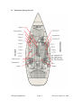

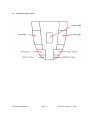


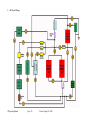


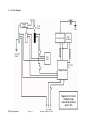

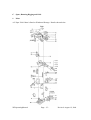
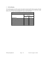


![ac circuit breaker panels [without meters] installation - thornam-shop](http://vs1.manualzilla.com/store/data/006886941_1-35cc363a8b64d2c248bc8206f0066550-150x150.png)