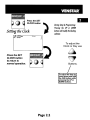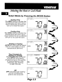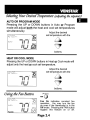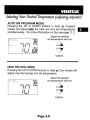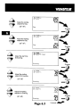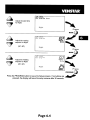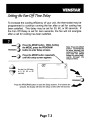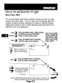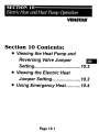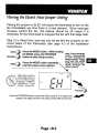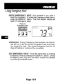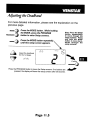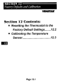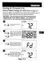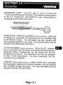
1
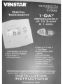
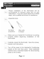
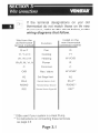
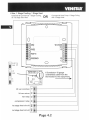
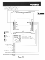
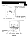
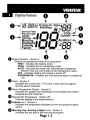
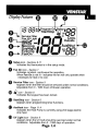
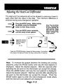
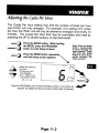
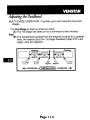
Quick-Start Guide
INSTEON™ Thermostat Adapter, Totaline™ / Venstar™
Model: #2441V
LED
Introduction
The INSTEON Thermostat Adapter adds remote control and monitoring to 3
compatible models of Totaline / Venstar brand thermostats. It simply
plugs into the bottom of compatible thermostats and communicates via
INSTEON RF giving you wireless remote control and monitoring from
anywhere in your home, or the world.
The 3 compatible models are:
1-Day Programmable Venstar Thermostat (30410A)
7-Day Programmable Venstar Thermostat (30411A)
7-Day Programmable, Dual-Fuel Venstar Thermostat (30412A)
Note: To use the above mentioned thermostats, make sure your install
location’s wiring has 5 wires or check with a local installer.
TM
Button
TM
INSTEON Thermostat Adapter
Installation
1)
Simply plug the INSTEON Thermostat Adapter into the jack on the bottom of your thermostat
Green LED will turn on
Un-Install
1)
2)
Open the front cover of the thermostat by gently pulling the right edge of the cover towards you
While pressing firmly on the small round button (center, bottom of thermostat) pull down gently on the INSTEON Thermostat Adapter
INSTEON Thermostat Adapter will disconnect from the thermostat
Adding your Thermostat Adapter to a Scene on an INSTEON Compatible Controller
For example, let’s say you would like to remotely control your thermostat to 73 degrees, heat mode from the comfort and convenience of your couch,
using the Scene A button on your RemoteLinc (If you want to use another INSTEON Compatible Controller, see its user manual)
Note: Linking your Adapter to a scene allows your thermostat to go to a chosen setting.
Here, you will link your Scene A button to “recall” both the setpoints and mode of the thermostat.
1)
Tap the mode button on your thermostat until the mode indicated is heat
2)
Tap the up and/or down arrows on your thermostat until the temperature set point is 73 degrees
3)
Press & hold the top of the Scene A button on your RemoteLinc (for about 10 seconds) until it beeps
LED will start blinking (Press & hold for 10 seconds works for just about every INSTEON-compatible Controller;
please check the controller’s owner’s manual if you need help)
4)
Press & hold the button on the INSTEON Thermostat Adapter (for about 5 seconds)
LCD display on your thermostat will briefly display all its characters, then return to normal
INSTEON Adapter’s LED will blink off faintly, then return to steady on
RemoteLinc will beep and its LED will stop blinking
5)
Tap the mode button on your thermostat (this will temporarily change the operating mode to allow you to test your remote control)
Your thermostat’s mode will change to cool
6)
Now to test your new link, tap the Scene A (up arrow) on your RemoteLinc
Your thermostat should return to heat mode with a 73-degree set point
7)
Repeat steps 1 through 6 for as many scenes and setpoints on your INSTEON-Compatible Controller as you wish.
Note: Sending an Off command will not change the mode or setpoints of the thermostat. These commands are ignored to minimize unintended results.
Note: Different set points can be linked to different buttons should you need more flexibility.
Page 1 of 2
Rev. 20080213
Quick-Start Guide
INSTEON Thermostat Adapter
Removing from a Scene
1)
2)
Put your Controller into “Delete from Scene” mode (usually “Unlinking” mode (two 10-second press & holds) – please check its Owner’s Manual if
you need help)
Press & hold the INSTEON Thermostat Adapter’s button for about 5 seconds
The LCD display on your thermostat will briefly display all its characters, then return to normal
The INSTEON Adapter’s LED will blink off faintly, then return to steady on
Factory Reset
1)
2)
3)
4)
Unplug the INSTEON Thermostat Adapter from your thermostat (see Un-Install section on page 1 for details)
Press & hold the button on the INSTEON Thermostat Adapter
While continuing to hold the button, plug the INSTEON Thermostat Adapter back into your thermostat
Continue to hold the button for approximately 5 seconds
All user settings will be erased and the unit restored to its factory settings
Advanced Operations
Using software, you will be able to integrate the automation of your thermostat with the wide array of INSTEON compatible products saving you
time and energy. For example, applications can include having an email sent to you if the temperature goes above or below any chosen set points,
have a “goodbye” scene automatically set back your thermostat, etc. – the applications are almost endless. Check with your favorite INSTEON
Compatible Software for their latest support for this product.
Specifications
INSTEON communications
RF
INSTEON Controller functionality
Not supported
INSTEON Responder functionality
Supported
INSTEON message repeating
Supported, always on
Mode control
Heat, Cool, Auto, OFF
Fan control
On, Auto
Degree format
Fahrenheit (Celsius is not available)
Maximum number of INSTEON
scenes / links
417
All Linking
Supported (10 sec set button push n hold)
Unlink
Supported (10 seconds press n hold, twice)
Heat set point
Supports all set points of Thermostat
Cool set point
Supports all set points of Thermostat
Temperature status request
Supported
Humidity status request
Supported
Mode status request
Supported
Fan status request
Supported
X10
Not supported
Dimensions
2.89” W x 1.75” H x 0.58” D
LED
Green
Interconnect type
Male, RJ10 4 conductor (aka RJ22)
Input power
5VDC, 30 ma max (supplied by thermostat)
Installation
Indoor use only
Approvals
FCC, Industry Canada
Warranty
2 years
FCC Compliance Statement
This device complies with FCC Rules Part 15.
Operation is subject to two conditions:
(1) This device may not cause harmful interference,
and
(2) this device must accept any interference that
may be received or that may cause undesired
operation. The digital circuitry of this device has
been tested and found to comply with the limits for a
Class B digital device, pursuant to Part 15 of the
FCC Rules. These limits are designed to provide
reasonable protection against harmful interference
in residential installations. This equipment
generates, uses and can radiate radio frequency
energy and, if not installed and used in accordance
with the instructions, may cause harmful
interference to radio and television reception.
However, there is no guarantee that interference will
not occur in a particular installation. If this device
does cause such interference, which can be verified
by turning the device off and on, the user is
encouraged to eliminate the interference by one or
more of the following measures:
x
Re-orient or re-locate the receiving antenna of
the device experiencing the interference.
x
Increase the distance between this device
and the receiver.
x
Connect the device to an AC outlet on a
circuit different from the one that supplies
power to the receiver.
x
Consult the dealer or an experienced radio/TV
technician.
WARNING! Changes or modifications to this unit
not expressly approved by the party responsible for
compliance could void the user's authority to
operate the equipment.
For HELP, call our friendly tech support @ 866-243-8018
SmartLabs Limited Warranty – SmartLabs warrants to the original consumer of this product that, for a period of two years from the date of purchase, this product will be free from defects in material and
workmanship and will perform in substantial conformity to the description of the product in the owner's manual and/or quick start guide. This warranty shall not apply to defects or errors caused by misuse
or neglect. © Copyright 2008 SmartLabs, 16542 Millikan Ave., Irvine, CA 92606-5027 – 866-243-8018 www.smartlabsinc.com
Page 2 of 2
Rev. 20080213
~CAUTION
Follow the Installation Instructions before proceeding.
Set the thermostat mode to "OFF" prior to changing
settings in setup or restoring Factory Defaults.
This device complies with Part 15 of the FCC Rules. Operation is
subject to the following two conditions: (1) this device may not cause
harmful interference, and (2) this device must accept any interference
received, including interference that may cause undesired operation.
c@us
LISTED
4Z95
Thermostat
T1700
DC
Tested to Comply
~with FCC Standards
FOR HOME OR OFFICE USE
Page i
Wire Connections
Sample Wiring
Diagrams
Test Operation
Calibrating the
Thermostat Sensors
TroubleShooting
Page iii
SECTION 1 - - - - - - - - - VENSTAR~
Preparation
1
ED I
r12~
I
Proper installation of the thermostat will be
accomplished by following these step by step
instructions. If you are unsure about any of these
steps, call a qualified technician for assistance.
Assemble tools
Flat Blade
Screwdriver
Wire cutter
& Stripper
~
Make sure your Heater/Air Conditioner is working
I properly before beginning installation of the
thermostat.
:EXR
Carefully unpack the thermostat. Save the screws,
I bracket, and instructions.
U1
I
Turn off the power to the Heating/Air Conditioning
system at the main fuse panel. Most residential
systems have a separate breaker for disconnecting
power to the furnace.
Page 1.1
SECTION 2 - - - - - - - - - -
Remove &oReplace the old Thermostat
GD
VENSTAR
Remove the cover of the old thermostat.
If it does not come off easily check for screws.
@I
Loosen the screws holding the thermostat base
or subbase to the wall, and lift away.
Disconnect the wires from the old thermostat.
Tape the ends of the wires as you disconnect
them, and mark them with the letter of the
terminal for easy reconnection to the new
thermostat.
Keep the old thermostat for reference purposes,
until your new thermostat is functioning properly.
Page 2.1
SECTION 3 - - - - - - - - - VENSTAR~
Wire Connections
If the terminal designations on your old
thermostat do not match those on the new
thermostat, refer to the chart below, or the
wiring diagrams that follow.
,
Wire from the
old thermostat
terminal marked
Function
Install on the
new thermostat
connector marked
G or F
Fan
G
Y1, Y or C
Cooling
Y1
W1, W or H
Heating
W1/0/B
Rh, R, M, Vr, A
Power
R
C
Common
C
OIB
Rev. Valve
W1/0/B*
W2
2nd Stage Heat
W2
RS+5
Remote Sensor +5vdc
RS+5**
RSGND
Remote Sensor Ground
RSGND**
RS2
Remote Sensor Signal #2
RS2**
* O/B is used if your system is a Heat Pump.
** For instructions on connecting these terminals
see page 4.6
Page 3.1
SECTION 4 - - - - - - - - - -
Sample Wiring Diagrams
VENSTAR~
Section 4 Contents:
• HVAC Equipment Wiring
4.2
• Installing the Outdoor Sensor. 4.6
Page 4.1
6 Wire, 1 Stage Cooling, 1 Stage Heat
Residential & Commercial 1 Stage Cooling,
with 1st stage Gas Heat
OR
Commercial Heat Pump 1 Stage Cooling
with 2 Stage Heat
o
o
1...----+--tIBlO W2
W1/0/B Oll:illl--+-----,
o
o RS2
o
o RS+5
o
o RSGND
1.:1-
lIJ-
1.:1-
lIJ-
Y1 0
o
ELEC ;
GAS
R111--+__-----,
G
0
o
o
o
R0
0
1I:iII1--+---'
C
R111---+'
1I:iII1--+_---,
~
HP
GAS
6 Conductor 18 gauge
unshielded cable from the
thermostat to the equipment.
•
~::~
24 vac common
24 vac return
fan relay
compressor relay
1st stage heat circuit
2nd stage heat circuit
Page 4.2
VENSTAR~
6 Wire, 1 Stage Cooling, 1 Stage Heat
Residential & Commercial 1 Stage Cooling,
with 1st stage Electric Heat
o
o
W1/0/B 0
Y10
'------+---fIlllO W2
o
o
o
o
o
GO
RS2
o
o
o
RS+5
o RSGND
~
RO
C
0
IJIII---t,
C)
-ELEC ~
-GAS 3
•
1.:1-
HP
GAS
lIJ~=~
6 Conductor 1B gauge
unshielded cable from the
thermostat to the equipment.
•
1(f)11--------------------I
a::: 1(f)11-------------------...J
C) 1(f)11---------------------J
;: 1(f)11----------------------'
~ 1(f)11-------------------------'
24 vac common U
24 vac return
fan relay
compressor relay
1st stage heat circuit
~ 17.i5Jr.t'
2nd stage heat circuit >
~1------------------------'
Page 4.3
VENSTAR~
6 Wire, 1 Stage Cooling, 2 Stage Heat
Residential Heat Pump with 0 Reversing
Valve 1 Stage Cooling, with 2 stage Heat
o
o
W1/0/B
Olllll---t---,
Y1 Olllll--+------,
G
Olllll--+----,
o
o
o
R Olllll--+---,
C Olllll---+,
C)
~-ELEC]
lIJ-
GAS
rjl -
HP
3
6 Conductor 18 gauge
unshielded cable from the
thermostat to the equipment.
Q-GAS
•
[I]::~
24 vac common
24 vac return
Fan Relay
Compressor Relay
Reversing Valve
2nd stage heat circuit
Page 4.4
·
VENSTAR~
G
6 Wire, 1 Stage Cooling, 2 Stage Heat
Residential Heat Pump with b Reversing
Valve 1 Stage Cooling, with 2 stage Heat
o
C)
L.....---+---f1B1 0 W2
W1/0/B
o
o RS2
oo RS+5
o
o RSGND
~-ELEC
llr
rjl-
l1li1--+-----,
Y1 Oo:ll--+------,
G
0
o
o
o
l1li1---4-----,
R Oo:ll--+--,
o
-;
0
C 00:11---1,
GAS
3
HP
6 Conductor 18 gauge
unshielded cable from the
thermostat to the equipment.
Q-GAS
•
~=~
24 vac common 0
24 vac return
Fan Relay
Compressor Relay
I~I f - - - - - - - - - - - - - - - - - - - - - '
a: 1(t)11-----------------------l
C)
1(t)11-------------------'
>I~I t - - - - - - - - - - - - - - - - - - - - - - - J
Reversing Valve .c
1(t)11-----------------------l
~ 17.&:\l'
2nd stage heat circuit >
ts!2J-t" I - - - - - - - - - - - - - - - - - - - - - - - . J
Page 4.5
VENSTAR~
Installing the Outdoor Sensor
The Outdoor Sensor measures outdoor air temperature and sends this
information to the thermostat; it measures temperature with a range of
_40° to 127°F.
The Outdoor Sensor should be connected to the thermostat using solid
conductor CAT 5, CAT 5e, or CAT 6 type network communication cable.
This is an unshielded cable with four twisted pairs of 24 gauge solid wire;
DO NOT use stranded cable. The cable length should not exceed 250
feet. If less than 75 feet of cable is required to connect the thermostat to
the Remote Sensor, a three conductor thermostat cable (18-24 gauge)
may be used; this cable is NOT suitable for any length greater than 75
feet.
IMPORTANT: Do no use shielded wire. Do not run sensor wiring in the
same conduit as the 24VAC thermostat wiring. Electrical interference
may cause the sensor to give incorrect temperature readings.
See the Outdoor Sensor accessory for further details.
Page 4.6
:EN
I
:EX'[,
Turn the power on to the Heating/Air Conditioning
system.
Press the MODE button repeatedly until the
HEAT icon appears on the display. Press the
UP or DOWN buttons until the set temperature
is 10 degrees above room temperature. The
furnace should turn on.
£TIl Press the MODE button repeatedly until the
Co
__
-
m,
COOL icon appears on the display. Press the UP
or DOWN buttons until the set temperature is 10
degrees below room temperature.
The air
conditioner should turn on.
NOTE: Most equipment has a time delay of 5 minutes between cool cycles. This feature is defeatable on the thermostat. Consult the Owners Manual under Setup, cycles per hour (page 11.3).
Press the UP button until the setpoint is equal to
the room temperature. Press the FAN button
to Fan On. The fan should turn on and run
continuously.
Page 5.1
SECTION 6 - - - - - - - - - -
Calibrating the Thermostat Sensors
aD
VENSTAR
Calibrating the Temperature and Humidity Sensors
Under normal circumstances it will not be necessary to adjust the
calibration of the temperature and humidity sensors. If calibration is
required, please contact a trained HVAC technician to correctly
perform the following procedure.
o
Ij.nn
,e ·uu Pm
MODE
MODE
FAN
•
Place the thermostat in the
OFF mode.
Press and hold the MODE
button.
While holding the
MODE button, press and hold
the FAN button for 5 seconds.
All icons will appear on the
display.
OFF
'8.88 Am
Program On Setup ",-,,-,
Pm StartStop l/
_
~
,.
H'L"_'
~:~~v
CQOL
AUTO EI~~~II~"~'o/OOutsl.de
SuMoTuWeThFrSa DeHumidify _
OFFON -
Morni.ng
DayN.lgflt
FanOn
Evening
Vacation
I'~"~' AuxHEAT
Lo " "
~
~
_"
_
-"
PRESS
THERMOSTAT SENSOR
Press the UP and DOWN buttons
at the same time twice. The
thermostat temperature will be
displayed and may be calibrated
using the UP or DOWN buttons.
TWICE
After calibration is complete, press the MODE button once to return to
normal operation.
Page 6.1
CALIBRATE
~
- SYMPTOM: The air conditioning does not attempt to
:Efl . I
turn on.
- CAUSE: The compressor timer lockout may prevent the
air conditioner from turning on for a period of time.
REMEDY: Consult the Owner's Manual in the Setup
section to defeat the cycles per hour and
compressor timeguard.
~
"SYMPTOM: The display is blank.
"U] - I CAUSE: Lack of proper power.
- ~- - REMEDY: Make sure power is turned on to the furnace
and that you have 24vac between R & Wand
24vac between R & C.
!XI ,
-
ru
SYMPTOM: The air conditioning does not attempt to
turn on.
CAUSE: The cooling setpoint is set too high.
REMEDY: Consult the Owner's Manual in the Setup
section to lower the cooling setpoint limit.
SYMPTOM: The heating does not attempt to turn on.
I CAUSE: The heating setpoint is set too low.
REMEDY: Consult the Owner's Manual in the Setup
section to raise the heating setpoint limit.
Page 7.1
In I
SYMPTOM: When controlling a residential heat pump,
and asking for cooling, the heat comes on.
CAUSE: The thermostat reversing valve jumper is set
for "b".
REMEDY: Set the reversing valve jumper for "0". See
pages 4.4 and 4.5.
SYMPTOM: When calling for cooling, both the heat
and cool come on.
CAUSE: The thermostat equipment jumper is configured
for "HP" and the HVAC unit is a Gas/Electric.
REMEDY: Set the equipment jumper for "Gas". See
pages 4.2 and 4.3.
Page 7.2
PIN 88-596
Rev. 3
&CAUTION
Follow the Installation Instructions before proceeding.
Set the thermostat mode to "OFF" prior to changing
settings in setup or restoring Factory Defaults.
This device complies with Part 15 of the FCC Rules. Operation is
subject to the following two conditions: (1) this device may not cause
harmful interference, and (2) this device must accept any interference
received, including interference that may cause undesired operation.
c@us
LISTED
4Z95
Thermostat
T1700
DC
Tested to Comply
~with FCC Standards
FOR HOME OR OFFICE USE
Page i
How to Use This Manual
VENSTAR"
The Table of Contents divides the thermostat features into sections
making it easier to quickly find information.
The first page of each section contains a more detailed Table of Contents
for each section, such as the example page shown below.
SECTION 14
nmers and Deadbands
e
VENSlD
Header shows section #
and title of section
•Section 14 Contents:
• Adjusting the Heat/Cool
Differential
• Adjusting the Cycles
Per Hour.
• Adjusting the Deadband
• Adjusting the Minutes of
Run-Time Before the
Next Stage
• Selecting 2nd Stage Turn
Off Temperature
14.2
14.3
14.4
Section contents
a.
14.6
14. 7
Visible section tab
on the side of the
page
Section and page #
Page 14.1
In addition, this manual also has an Index to help you find any information
regarding this thermostat quickly.
Page ii
Glossary ofTmns
VENSTAR"
Auto-Changeover: A mode in which the thermostat will turn on
the heating or cooling based on room temperature demand.
Cool Setpoint: The warmest temperature that the space should
rise to before cooling is turned on (without regards to
deadband).
Deadband: The number of degrees the thermostat will wait, once
setpoint has been reached, before energizing heating or cooling.
Differential: The forced temperature difference between the
heat setpoint and the cool setpoint.
Heat Setpoint: The coolest temperature that the space should
drop to before heating is turned on (without regards to
deadband).
Icon: The word or symbol that appears on the thermostat
display.
Mode: The current operating condition of the thermostat (Le. Off,
Heat, Cool, Auto, Program On).
Non-Programmable Thermostat: A thermostat that does not
have the capability of running the Time Period Programming.
Programmable Thermostat: A thermostat that has the capability
of running the Time Period Programming.
Temperature Swing: Same as Deadband.
Time Period Programming: A program that allows the
thermostat to automatically adjust the heat setpoint and/or the
cool setpoint based on the time of day.
Page iii
Basic Operation
lewlng t e ut oor
Tem erature
Programming the
Dally Schedule
rogrammlng t e an
Operation
Thermostat Display
Options
Programming RunTime Alerts
Timers and Deadbands
Factory Defaults and
Calibration
Accessories
Advanced Setup Table
I
Pageiv
SECTION 1 - - - - - - - - - - -
Getting to Know Your Thennostat
1
VENSTAir
Section 1 Contents:
• Front Panel Buttons
• Display Features
Page 1.1
1.2
1.3
Front Panel
Warmer Button [sometimes referred]
(glows red)
to as the UP button
Backlit LCD Display
-;:::::::::::::::::======P==========::::::::::::'::-
, :00....
AUTO
o
-, -,
'U
I,
COOL
11- lEAl
o
Cooler Button [sometimes refer
(glows blue)
red to as the
DOWN button
Heat or Cool Demand Indicator Mode
Red = Heat, Green = Cool
Button
'U
,~.nn
'C"
. UUftm
AUTO
, ,
,
_,0
Ie
COOL
12
~
:..
V
"...
.•. ...
QUICK RELEASE FOR
ACCESSORY PORT -5-;z.~===;t=~::~Jl.J.::::::::U'---\---~
(pg.13.1)
FAN
EMRG HT. OUTDOORo PROGRAM
Page 1.2
SET
CLOCK
J
Display Features
~ '0- ODAm Program On Setup' ........
~ IU·OOPm StartStop J.j
H,HH rO
~
0----. ~:~~~E:~~~, '~J '~JO CQOl ~
AUTO
(
(
Outside
Evening
FanOn
-
-
-""
~~
~':fr~~g-,,-,,-,AUXHEAT"~
DayN.lgflt
La " "
-V
o
e
•
«»
•
Mode Indicators - Section 4 '
•
Selects the operational mode of the equipment.
HEAT - Indicates the heating mode.
COOL - Indicates the air conditioning mode.
AUTO - Indicates the system will automatically changeover
between heat and cool modes as the temperature varies.
OFF - Indicates heating and cooling is turned off.
PROGRAM ON - Indicates the time period program is enabled to
run.
Clock - Section 3
Indicates the current time. This clock is also used to program
the time period schedule.
Room Temperature Display - Section 5
Indicates the current room temperature and displays the outdoor
temperature when selected.
Desired Set Temperature - Section 4/5
Indicates desired room temperature(s) .
Outside icon - Section 5
Indicates the temperature displayed is from the optional outdoor
sensor.
<D Morning,
Day, Evening & Night icons - Section 6
Indicates the day part of the time period program.
Page 1.3
Display Features
'O.O'JA
, L' · L' 0
Pm
~:~~~ E:~~~I
~
N~
ProgramO
StartStop
etup,.~,.~,
[)
'- '-
,..., ,"',0 CQOL
HI' "
,
Outside
Morni.ng , , - , , - , AuxHEAT
DayN.lgflt
La " "
~ Evening
--""
~ L..-F_a_n_O_n
~
__~
_
I.......-
___I
8
Setup icon - Sections 6-11
Indicates the thermostat is in the setup mode.
«8 FanIndicates
On icon - Section 7
constant, continuous fan operation.
o
~
When Fan On is not lit - indicates the fan will only operate when
necessary to heat or to cool.
Service Filter icon - Section 9
Appears when the filter should be serviced under normal conditions.
Adjustable from 0 - 1950 hours of blower operation.
iii Indicates
icon - Section 8
.
the keypad has been locked.
m
StartStop icon - Section 6
Appears when programming timer functions.
@
~
AuxHeat icon - Page 11.4
Indicates the Heat Pump is currently using 2nd stage electric
strip heat.
UV Light icon - Section 9
Appears when the UV bulb should be serviced under normal
conditions. Adjustable from 0 - 1990 days of operation.
Page 1.4
SECTION 2
Quick Start
VENSTAR®
Section 2 Contents:
• Setting the Clock
• Selecting the Heat or Cool
~ocfe
2.2
2.~
• Selecting Your Desired
• Using the Fan Button
2.4
Note: Following the instructions in this section will allow you to
operate your thermostat using the factory default settings. These
settings are depicted in the illustrations throughout this manual.
Page 2.1
VENSTAR®
Press the SET
CLOCK button
During Setup &Programming:
Pressing the UP or DOWN
Duttons willmodifythe Hashing
seledion.
Setting the Clock
nnAm
,'2··uu
Setup
I
I
To adjust the
Clock or Day use
Press the SET
CLOCK button
to return to
normal operation.
Buttons.
To adjust the time by
hours press and hold
the FAN button while
pressing the UP or
DOWN buttons.
Page 2.2
Sekcting the Heat or Cool Mode
Select Mode by Pressing the MODE Button
Heating Only
The HEAT setting indicates the
temperature the room has to
reach before the furnace will
turn on to heat the room.
o
"ILl 68
HEAT
Press
MODE
16
Cooling Only
The COOL setting indicates the
temperature the room has to
reach before the air conditioner
will turn on to cool the room.
COOL
Press
MODE
Heating or Cooling
A UTO will automatically select
heat or cool based on room
temperature demand.
AUTO
Press
MODE·
Time Schedule for
Heating or Cooling
The Program On setting will
activate the time period
programming for the cooling
or heating setpoint ONLY
(Morning, Day, Evening
& Night Periods).
Off
OFF indicates both heating
and air conditioning
systems are turned off.
t
::J • n If
tL 'l...IU
Program On
Pm
o
Day
16
COOL
"ILl 58
OFF
Page 2.3
Press
MODE
Selecting Your Desired Temperature (adjusting the sdpoints)
AUTO OR PROGRAM MODE
Pressing the UP or DOWN buttons in Auto or Program
mode will adjust both the heat and cool set temperatures
simultaneously.
Ad'JUst th e deSlre
. d
,,-
I If'
II~I '-''-'
co
o
AUTO
set temperature with the
..
COOL
HEAT
buttons.
HEAT OR COOL MODE
Pressing the UP or DOWN buttons in Heat or Cool mode will
adjust only the heat or cool set temperature.
Adjust the desired
set temperature with the
,,o
'0
COOL
buttons.
Using the Fan Button
AUTO
Press
FAN
Fan On indicates constant fan
operation. You may turn the fan
on even if the thermostat is in the
Off mode. Pressing the FAN button
toggles this feature on or off.
FanOn
Page 2.4
Section 3 Contents:
• Setting the Clock
3.2
Note: During setup & programming pressing the UP or DOWN
buttons will modify the flashing selection.
Page 3.1
Press the SET
CLOCK button
Setting the Clock
,j. nnAm
'C'UU
During Setup & Programming:
Pressing the UP or DOWN
Duttons willmodifythe Hashing
se/edion.
Setup
To adjust the
Clock or Day use
Press the SET
CLOCK button
to return to
normal operation.
Buttons.
To adjust the time by
hours press and hold
the FAN button while
pressing the UP or
DOWN buttons.
Page 3.2
Section 4 Contents:
• Programmable or NonProgrammable Thermostat
4.2
• Manual or Auto-Changeover
Thermostat
4.~
• Selecting the Operating Mode.....4.4
• Selecting Your Desired
Temperature
4.lJ
Note: During setup & programming pressing the UP or DOWN
buttons will modify the flashing selection.
Page 4.1
~o~amm~k~N~~~o~amm~k
Thennostat
When the very simplest operation is desired, this thermostat may
be configured to be non-programmable, with or without AutoChangeover. Follow the step below.
If 'NO' is selected, the thermostat will lockout the Program On screen;
only the Off, Heat, Cool, and Auto screens may be accessed by
pressing the MODE button.
Select 'YES' if you would like your thermostat to be programmable,
then the Program mode will be accessible through the use of the
MODE button.
MODE
PROGRAM
Press the MODE button. While holding
the MODE, press the PROGRAM
button to enter Setup screens.
Note: Press the MODE
button momentarily
to move through the
setup screens. Press
and hold the MODE
button to move backwards through the
setup screens.
I
I
Select Yes if you would like
the thermostat to be program
mabie or No for non-program
mabie.
Press
~
PROGRAM ' "
Press the PROGRAM button to leave the Setup screens. If no buttons are ~
pressed, the display will leave the setup screens after 30 seconds.
Page 4.2
Manual orAuto-Changeover
Thamostat
When the very simplest operation is desired, this thermostat may
be configured to be a manual heat and cool thermostat, with or
without time period programmability. Follow the step below.
The thermostat may be programmed to function as a Heat Only or
Cool Only thermostat by selecting 'NO' in the setup screen below.
This will lockout the Auto-Changeover screen and only allow the Off,
Heat, Cool, and Program On screens to be accessed.
MODE
PROGRAM
MODE
Press the MODE button. While holding
the MODE, press the PROGRAM
button to enter Setup screens.
Note: Press the MODE
button momentarily
to move through the
setup screens. Press
and hold the MODE
Press the MODE button repeatedIY~;
.
button to move backuntil this setup screen appears.
wards tlJrough the
setup screens.
~E5
YES
Select Yes if you would
like the thermostat to
be Auto-ChaQgeover or
No for a Heat Only and
Cool Only Thermostat.
AUTO
Setup.
2
~
~
Press
NO
PROGRAM
Press the PROGRAM button to leave the Setup screens. If no buttons ar~
pressed, the display will leave the setup screens after 30 seconds.
Page 4.3
Operating Mode when the Thawostat
is Configured to be:
NON-PROGRAMMABLE WITH MANUAL CHANGEOVER - If the
thermostat is configured to be a non-programmable thermostat with
Manual Changeover, the following screens will be available by
pressing the MODE button.
Select the Mode by Pressing the MODE Button
Heating Only
The HEAT setting indicates the
temperature the room has to
reach before the furnace will
turn on to heat the room.
~
,-"
-HEAT
"",,-
Cooling Only
The COOL setting indicates the
temperature the room has to
reach before the air conditioner
will turn on to cool the room.
'0
COOL
Press
MODE
~
~
Press
MODE
~
Off
OFF indicates both heating
and air conditioning
systems are turned off.
OFF
,
Page 4.4
Operating Mode when the nzennostat
is Configured to be:
NON-PROGRAMMABLE WITH AUTO-CHANGEOVER - If the
thermostat is configured to be a non-programmable thermostat
with Auto-Changeover, the following screens will be available by
pressing the MODE button
Select the Mode by Pressing the MODE Button
Heating Only
The HEAT setting indicates the
temperature the room has to
reach before the furnace will
turn on to heat the room.
I
ILl 6B
,,6
HEAT
-~
Cooling Only
The COOL setting indicates the
temperature the room has to
reach before the air conditioner
will turn on to cool the room.
Heating or Cooling
A UTO will automatically select
heat or cool based on room
temperature demand.
Press
MODE
COOL
f)
.
AUTO
"I
,,'0
Press
MODE
COOL
Press
MODE
Off
OFF indicates both heating
and air conditioning
systems are turned off.
OFF
Page 4.5
Heating Only
The HEAT setting indicates the
temperature the room has to
reach before the furnace will
turn on to heat the room.
Press
Cooling Only
The COOL setting indicates the
temperature the room has to
reach before the air conditioner
will turn on to cool the room.
Time Schedule for
Heating Only
The HEAT Program On setting
will activate the time period
program for the heating
setpoint ONLY (Morning, Day,
Evening & Night Periods).
Time Schedule for
Cooling Only
The COOL Program On setting
will activate the time period
program for the cooling
setpoint ONLY (Morning, Day,
Evening & Night Periods).
Press
ILl
I
:::J . ,-,(,
11_ .. I...H ...J Pm
~
Program On
0
HEAT
Day
I
:::J . ii il
it. . t...JI.,,) Pm
Program On
58
,-
Day
Su
OFF
Page 4.6
~
Press
MODE
'0 ~
COOL
'-'.fir,
Ie
. ULI Pm
Off
OFF indicates both heating
and air conditioning
systems are turned off.
MODE
~
Press
MODE
~
Operating Mode when the nzowostat
is Configured to be:
PROGRAMMABLE WITH Auto-Changeover - If the thermostat is
configured to be a programmable thermostat with Auto-Changeover,
the following screens will be available by pressing the MODE button.
lEI
Select the Mode by Pressing the MODE Button
Heating Only
The HEAT setting indicates the
temperature the room has to
reach before the furnace will
turn on to heat the room.
t.:).nrt
,1L • LJ~j Prn
S~j
()
HEAT
CO
'-'0
,
Press
#c .
,,-
"'-
t_i~_f Pm
311
COOL
AUTO
HEAT
C'J
t
:t . n n
if: ·i..ll.JPrn
'-'0
Program On
<'"
t:.h<
,'0
COOL
Day
MODE ';
~
~
Press
MODE.
~
58 ~
HEAT
Press
MODE
Off
OFF indicates both heating
and air conditioning
systems are turned off.
MODE
COOL
1',,(1tl
Time Schedule for
Heating or Cooling
The Program On setting wil
activate the time period
programming for the cooling
or heating setpoint ONLY
(Morning, Day, Evening
& Night Periods).
Press
,,~
'0
~
Cooling Only
The COOL setting indicates the
temperature the room has to
reach before the air conditioner
will turn on to cool the room.
Heating or Cooling
A UTO will automatically select
heat or cool based on room
temperature demand.
~
OFF
Page 4.7
~
Selecting Your Desired Temperature (adjusting setpoints)
AUTO OR PROGRAM MODE
Pressing the UP or DOWN buttons in Auto or Program
modes will adjust both the heat and cool set temperatures
simultaneously. For more information on this see page 11.2.
,,o
Adjust the desired
set temperature with the
'0
COOL
AUTO
,-"
--
HEAT
""
buttons.
HEAT OR COOL MODE
Pressing the UP or DOWN buttons in Heat or Cool modes will
adjust only the heat or cool set temperature.
,,-
",-
Adjust the desired
set temperature with the
COOL
buttons.
Page 4.8
SECTION 5 - - - - - - - - - -
Viewing the Outdoor Temperature
VENSTAir
Section 5 Contents:
• Viewing the Outdoor
Jrel11l'erCiture
Page 5.1
~.~
Viewing the Outdoor Temperature
This requires an outdoor sensor (optional accessory) to be installed
(see page 4.6 of the Installation Instructions). To read the
tempo
erature from the Outdoor Sensor, press the OUTDOOR button.
The display will then show the current outdoor temperature.
Press the OUTDOORo
button.
The current outdoo
temperature will be
displayed. This reading
is from the senso
connected to RS2.
I, . .,
"
..
,O_O_ut_si_de"""'+-_ _....
,
---
Current outdoor
temperature.
Press the OUTDOORo
button to return to
normal operation.
Note: If no sensors are connected 2 dashes [- -] will appear on the display.
Page 5.2
SECTION 6 - - - - - - - - - -
Programming the Daily Schedule
VENSTAR~
Section 6 Contents:
lEI.
Programming a Daily
~~I1~ctLlI~
ti.~
Page 6.1
Programming a Daily Scheduk
Press the PROGRAM button to enter time period programming.
C
,""Am
o'uu
Start
Adjust the start time
for Morning.
IV!orning
Press
MODE
',:J
'0
Adjust the cooling
setpoint for Morning.
(35°- 99°)
COOL
Morning
Press
MODE
Adjust the heating
setpoint for Morning.
(35°- 99°)
COOL
",
'L'
HEAT
Morning
nnAm
8 ..UU
Press
MODE
Start
Adjust the start time
for Day.
Day
Press
MODE
Page 6.2
Continued
~
(J.nnAm
85
,-,. '-'LI
COOL
Adjust the cooling
setpoint for Day.
(35°· 99°)
Day
~
Press
MODE
",~
--
O·nnAm
U . '-''-'
II I
Adjust the heating
setpoint for Day.
OJC ~
COOL
(35°· 99°)
HEAT
Day
Press
MODE
s·nn
'UU Pm
~
Start
Adjust the start time
for Evening.
~
Evening
Press
C . fil;
O'UUPm
Adjust the cooling
setpoint for Evening.
(35°- 99°)
Evening
c·nn
LILt Pm
(J'
Adjust the heating
setpoint for Evening.
MODE
,o~~
"-'
COOL
HEAT
(35°· 99°)
Evening
Page 6.3
,n
Press
MODE
IU
Continued~
In.nn
IU· UU Pm Start
Adjust the start time
for Night.
Night
Press
MODE
tf;. f i l i
tU' WLI
Pm
Adjust the cooling
setpoint for Night.
82~
COOL~
(35°- 99°)
Night
Press
MODE
tr,. ,-,#-,
ILl'
WLt
Pm
Adjust the heating
setpoint for Night
t"...
l'l~
COOL~
(35°- 99°)
HEAT
Night
'--
-:)
ti£:
---1
Press
PROGRAM
Press the PROGRAM button to leave the Setup screens. If no buttons are
pressed, the display will leave the setup screens after 30 seconds.
Page 6.4
~
SECTION 7 - - - - - - - - - -
Programming the Fan Operation
VENSTAR~
Section 7 Contents:
• Using the Fan Button
• Setting the Fan-Off Time
• Delay
Page 7.1
7.2
7.3
Using the Fan Button
When the fan is set for automatic operation it will energize any time
there is a call for heating or cooling, otherwise the fan will remain off.
Pressing the FAN button will energize the fan and display the FanOn
icon on the thermostat display. To operate the fan in the automatic
mode, press the FAN button again and the FanOn icon will disappear.
Press
FAN
1")>>
nn
Ie . tJt.lPrn
AUTO
Fan On indicates constant fan
operation. You may turn the fan
on even if the thermostat is in the
Off mode. Pressing the FAN button
toggles this feature on or off.
FanOn
Page 7.2
Setting the Fan-OffTIme Delay
To increase the cooling efficiency of your unit, the thermostat may be
programmed to continue running the fan after a call for cooling has
been satisfied. This delay may be set for 30, 60, or 90 seconds. If
the Fan Off Delay is set for zero seconds, the fan will not energize
after a call for cooling has been satisfied.
MODE
PROGRAM
MODE
Press the MODE button. While holding
the MODE, press the PROGRAM
button to enter Setup screens.
Press the MODE button repeatedly
until this setup screen appears.
"'"
~
. nn
·uu
Set the Fan Off Delay
to O. 30, 60, or 90
seconds.
FanOn
Setup
Note: Press the MODE
button momentarily
to move through the
setup screens. Press
and hold the MODE
button to move backwards through the
setup screens.
.,-,
Press
PROGRAM
Press the PROGRAM button to leave the Setup screens. If no buttons are ~~
pressed, the display will leave the setup screens after 30 seconds. ~
Page 7.3
Section 8 Contents:
• Turning On/Off the
~Clc:lrlight
lJ.~
• ProgrClmming the ThermostCit
to DisplClY Temperature in
FClhrenheit or Celsius
• Loc:king/Unloc:lring the
~eYPClci
•
•
lJ.~
~.lJ.~
Page 8.1
Turning On/Offthe Backlight
Press the MODE button. While holding
the MODE, press the PROGRAM
button to enter Setup screens.
MODE
PROGRAM
MODE,
Note: Press the MODE
button momentarily
to move through the
setup screens. Press
and hold the MODE
Press the MODE button repeatedlY~ button to move backwards through the
until this setup screen appears.
setup screens.
, ,
Setup
Select backlight operation:
AUTO - Light from 6pm to
6am nightly.
ON - Light continuously.
OFF - Light for 8 seconds
after a button press.
AUTO
L
I
L'..J'
'~
Press
MODE
Programming the Thmnostat to Display
Temperature in Fahrenheit or Celsius
,,-
Setup
c
Select thermostat
operation in degrees
Fahrenheit or Celsius.
F
Press
PROGRAM
Press the PROGRAM button to leave the Setup screens. If no buttons are
pressed, the display will leave the setup screens after 30 seconds.
Page ~.2
~
Locking/Unlocking the Ktypad
To prevent unauthorized use of the thermostat, the front panel
buttons may be disabled. To disable, or 'lock' the keypad, press
and hold the MODE button. While holding the MODE button,
press the UP and DOWN buttons together. The ~ icon will
appear on the display, then release the buttons.
1:;).t1'-'
II.: • ULI Pm
Press all three
buttons in the order
outlined above for
keypad lockout
~
~
~
~O
,,II.'
COOL
AUTO
,-"
II~, I.'-"
"
MODE
,
HEAT
To unlock the keypad, press and hold the MODE button. While
holding the MODE button, press the UP and DOWN buttons
together. The ~ icon will disappear from the display, then
release the buttons.
Page 8.3
SECTION 9 - - - - - - - - - -
Programming Run-Time Alerts
GD
VENSlAR
Section 9 Contents:
• Setting and Resetting the
Service Filter (Fan Run-Time)
~/el1f..•...... ~ .........••.••..........•••... ~.~
• Setting and Resetting the UV
Light Run-Time ~/el1f••........... ~.3
Page 9.1
How to Set and Reset the Service Filter
(Fan Run-TIme) Alert
This counter keeps track of the number of hours of fan run-time
whether the fan is energized in the Heating or Cooling modes, or in
stand alone fan operation. The Service Filter icon will appear after the
preset number of hours of fan run-time in step #7 (below) has been
achieved. Setting this counter to zero in step #7 will prevent the
Service Filter icon from ever appearing.
MODE
PROGRAM
MODE
Press the MODE button. While holding
the MODE, press the PROGRAM
button to enter Setup screens.
Note: Press the MODE
button momentarily
to move through the
setup screens. Press
and hold the MODE
Press the MODE button repeatedly
button to move back•
~ards through the
until. thiS
setup screen appears.
setup screens.
IHours the fan has .L
Irun since last resetr-I----1~:::iiloo.~nn------;:s~et;;;u;;-p
--,:;;_;-,
~U
Press
Reset the counter to 0 to
remove the Service Filter
icon from the display.
"-
Service Filter
FAN
Press
MODE
n
Adjust the number of
hours, in increments of
50, the fan will run
before the Service
Filter icon appears on
the display. 0 = off.
u
Setup
Service Filter
Press
PROGRAM
(0 - 1950 hours)
Press the PROGRAM button to leave the Setup screens. If no buttons are
pressed, the display will leave the setup screens after 30 seconds.
Page 9.2
~
How to Set and Reset the UV Light
Run~TIme Altrt
This counter keeps track of the number of days since the UV Light
counter has been reset. The UV Light icon will appear after the
number of days has been achieved, as shown in step #9 (below).
Setting the counter to zero in Step #9 will prevent the Service UV
Light icon from ever appearing.
MODE
PROGRAM
MODE
Press the MODE button. While holding
the MODE, press the PROGRAM
button to enter Setup screens.
Note: Press the MODE
button momentarily
to move through the
setup screens. Press
and hold the MODE
Press the MODE button repeatedly
button to move backwards through the
.
•
untIl thIS setup screen appears.
~etup screens.
r;:::D~aY-S-s";"'"in-ce--:t~he--:u:-:,:v-:-:L:-;-ig-;'h~tLI------+==~n----S;W;-__;:;;;l
I icon has been reset
~
I
Press
n
Setup
0
U
Reset the counter to 0 to
remove the Service UV
Light icon from the display.
"
Service
UV Light
FAN
MODE
Press the MODE button repeatedly
until this setup screen appears.
~
n
U
Adjust the number of days
in increments of 10 before
the UV Light icon appears
on the display. 0 = off.
Service
UV Light
Setup
"
,
-
(0 - 1990 days)
PROGRAM
Press the PROGRAM button to leave the Setup screens. If no buttons are
pressed, the display will leave the setup screens after 30 seconds.
(.~
Press
Page 9.3
~
SECTION 1 0 - - - - - - - - - -
Electric Heat and Heat Pump Operation
VENSTAir
Section 10 Contents:
• Viewing the Heat Pump and
Reversing Valve Jumper
Setting
• Viewing the Electric Heat
Jumper Setting
• Using Emergency Heat
Page 10.1
10.2
10.3
10.4
Viewing the Heat Pump and
Reversing Valve Jumper Settings
Step~
10 and 11 are 'Read Only' and may only be set with the
jumpers on the circuit board of the thermostat (see page 4.4 of
the Installation Instructions).
MODE
PROGRAM
MODE.
Press the MODE button. While holding
the MODE, press the PROGRAM
button to enter Setup screens.
Press the MODE button repeatedly
,
until this setup screen appears.
Note: Press the MODE
button momentarily
to move through the
setup screens. Press
and hold the MODE
button to move backwards through the·
~ setup screens.
Setup
I"
1f•.•J
ON = Heat Pump
operation
OFF Gas Electric
operation
=
OFF
Press
Indicates that the
thermostat jumper
is set for an 0
reversing valve
(energize in cooling)
or a b reversing valve
(energize in heating).
,
Setup
la'
I
I
I'
MODE
~
~
Press
PROGRAM
Press the PROGRAM button to leave the Setup screens. If no buttons are ~
pressed, the display will leave the setup screens after 30 seconds.
Page 10.2
Viewing the Electric Heat Jumper Setting
Placing the jumper on ELEC will cause the thermostat to turn on the
fan immediately any time there is a heat demand. Since most gas
furnaces control the fan, this feature should be off unless it is
necessary for the thermostat to energize the fan with first stage heat.
Step 12 is 'Read Only' and may only be set with the jumpers on the
circuit board of the thermostat (see page 4.3 of the Installation
Instructions).
MODE
PROGRAM
MODE
®
Press the MODE button. While holding
Note: Press the MODE
the MODE, press the PROGRAM
button momentarily
to move through the
button to enter Setup screens.
setup screens. Press
and hold the MODE
Press the MODE button repeatedly ~button to move backuntil this setup screen appears
wards through the
.
setup screens.
--, ,
Setup
ON indicates that the
thermostat jumper is
set for Electric Heat
operation, or OFF for
Gas/Electric or Heat
Pump operation.
OFF
"
Press the PROGRAM button to leave the Setup screens. If no buttons are
pressed, the display will leave the setup screens after 30 seconds.
Page 10.3
Press
PROGRAM
"
~
Using Emergency Heat
ENTER EMERGENCY HEAT: Only available if you have a
Heat Pump installed. To initiate the Emergency Heat feature,
press the EMER HT. button. The Cool setpoint display will
read 'EH' (emergency heat).
Press for
Emergency Heat
eL'
«iIIII!
.... 0
,_,
,.
,
~
1.:"
HEAT
'LI
I I
OPERATION: During Emergency Heat operation the thermostat will turn on the fan and the 2nd stage of heat when there
is a demand for heat. Also during Emergency Heat the 1st
stage of heating or cooling will be unavailable.
EXIT EMERGENCY HEAT: Follow the same steps as entering
Emergency Heat by pressing the EMER HT. button. During
Emergency Heat, only OFF and HEAT modes are available
by pressing the MODE button.
Page 10.4
SECTION 11
Timers and Deadbands
VENSTAR®
Section 11 Contents:
• Adjusting the Heat/Cool
Differential
• Adjusting the Cycles
Per Hour.
• Adjusting the Deadband
Page 11.1
11.2
11.3
11.4
Adjusting the Heat/Cool Differential
The Heat and Cool setpoints will not be allowed to come any closer to
each other than the value in this step. This minimum difference is
enforced during Auto-Changeover operation.
MODE
PROGRAM
MODE·
Press the MODE button. While holding
the MODE, press the PROGRAM
button to enter Setup screens.
Note: Press the MODE
button momentarily
to move through the
setup screens. Press
and hold the MODE
button to move backwards through the
setup screens.
Press the MODE button repeatedly
until this setup screen appears.,
~
d IF
Adjust the minimum
difference between
cooling & heating
setpoints.
Setup
,='
"
COOL
HEAT
(0° - 6°)
Press the PROGRAM button to leave the Setup screens. If no buttons
are pressed, the display will leave the setup screens after 30 seconds.
~
Note: To increase the spread between the heating and cooling
setpoints, press the MODE button until only the heat setpoint is
displayed. Adjust the desired setpoint. Wait two seconds after
adjusting the set point so the thermostat can accept the change.
Press the MODE button until only the cool setpoint is displayed.
Adjust the desired setpoint. Wait two seconds after adjusting the
set point so the thermostat can accept the change. Press the
MODE button again to enter the Auto-Changeover mode where
both the heat and cool setpoints are displayed.
Page 11.2
Adjusting the Cycks Per Hour
The Cycles Per Hour setting may limit the number of times per hour
your HVAC unit may energize. For example, at a setting of 6 cycles
per hour the HVAC unit will only be allowed to energize once every 10
minutes. The Cycles Per Hour limit may be overridden and reset by
pressing the UP or DOWN buttons on the thermostat.
MODE
PROGRAM
MODE .
Press the MODE button. While holding
the MODE, press the PROGRAM
button to enter Setup screens.
Note: Press the MODE
button momentarily
to move through the
setup screens. Press
and hold the MODE
button to move backwards through the
setup screens.
Press the MODE button repeatedly
until this setup screen appears.
~
Setup
,"
.."
Select the cycles per
hour limit.
d=cycles per hour
limit defeated.
d1=d + defeat 5 min.
compressor lockout.
(d1,d,2-6)
I
Press the PROGRAM button to leave the Setup screens. If no buttons are
pressed, the display will leave the setup screens after 30 seconds.
Page 11.3
l1li
'L'
I
Press
PROGRAM
~
VENSTAR
Q9
Adjusting the Deadband
MULTI-STAGE OPERATION - Controls up to two Heat and one Cool
stages.
The 2nd Stage of heat is turned on when:
(A) The 1st Stage has been on for a minimum of two minutes.
And
(B) The temperature spread from the setpoint is equal to or greater
than: the setpoint plus the 1st stage deadband (step #15, next
page), plus two degrees.
Cooling
Heating
Deadband
2nd Stage
turn on
1st Stage
turn on
Deadband
Heat
Setpoint
Deadband
Cool
Setpoint
1st Stage
turn on
+- DECREASE -I TEMPERATURE I-INCREASE - - .
Page 11.4
Adjusting the Deadband
For more detailed information, please see the explanation on the
previous page.
MODE
PROGRAM
MODE
Press the MODE button. While holding
the MODE, press the PROGRAM
button to enter Setup screens.
Press the MODE button repeatedly
until this setup screen appears.
~
..J .t...
I~J (:1
Adjust the deadband
for the 1st stage.
,,-
Setup
Note: Press the MODE
button momentarily
to move through the
setup screens. Press
and hold the MODE
button to move backwards through the
setup screens.
,.....-,
1''_
011
~
Press the PROGRAM button to leave the Setup screens. If no buttons are
pressed, the display will leave the setup screens after 30 seconds.
Page 11.5
~
SECTION 12 - - - - - - - - -
Factory Defaults and Calibration
VENSTAil
Section 12 Contents:
• Resetting the Thermostat to the
Factory Default Settings
12.2
• Calibrating the Temperature
Sensor
12.3
Page 12.1
Resetting the Thennostat to the
Factory Default Settings (for default values see page 1+1)
If, for any reason, you desire to return all the stored settings back to
the factory default settings, follow the instructions below.
WARNING: This will reset all Time Period and Advanced
Programming to the default settings. Any information
entered prior to this reset may be permanently lost.
o
,J.nn
,e
·UUPm
MODE
MODE.
FAN
Place the thermostat in the
OFF mode.
Press and hold the MODE
button.
While holding the
MODE button, press and hold
the FAN button for 5 seconds.
All icons will appear on the
display.
OFF
'.-'8
HID
'8·88
Am
On Setup
,.
Pm Program
StartStop
D
SuMoTuWeThFrSa DeHumidify"
,-, :......,
~:~~~ r::~~, I~' I~'% Outsl.de
CQOL
AUTO
OFFON -
ee
Vacation
Morni.ng ,,~,,~,AUXHEAT
DayN)ght
La
Evenmg
-,~ ,-:
FanOn
_
_
~~
FAN
After all of the icons appear,
release the MODE and FAN
buttons. Then press and hold
the FAN button for 5 seconds.
,-- I
,:;). nn
'e: . UU Pm
MODE
After the letters Fd appear on
the display (Factory Default),
release the FAN button. Press
the MODE button once to
return to normal operation.
OFF
Page 12.2
,-"-
Calibrating the Temperature and Humidity Sensurs
Under normal circumstances it will not be necessary to adjust the
calibration of the temperature and humidity sensors. If calibration is
required, please contact a trained HVAC technician to correctly
perform the following procedure.
o
,'2'·uu
"" Pm
MODE
MODE,
FAN
Place the thermostat in the
OFF mode.
Press and hold the MODE
button.
While holding the
MODE button, press and hold
the FAN button for 5 seconds.
All icons will appear on the
display.
OFF
'B'BBAm
On S~UP'a8
,.
Pm Program
StartStop
SuMoTuWeThFrSa DeHumidify" HI
n
:. . . .,
~::;'~~ [1~~~1 '~J '~JO/OOutside
COOL
AUTO
OFFON -
Morm.ng
DayNlglit
Evening
FanOn
11-"-' LoBe
Vacation
AuxHEAT
__
-
PRESS
THERMOSTAT SENSOR
Press the UP and DOWN buttons
at the same time twice. The
thermostat temperature will be
displayed and may be calibrated
using the UP or DOWN buttons.
TWICE
After calibration is complete, press the MODE button once to return to
normal operation.
Page 12.3
CALIBRATE
SECTION 13
Accessories
VENSTAR®
ACCESSORY PORT - The RJ11 Jack is used to connect the
T1700 to the IR Receiver (ACC0431) for wireless communication
or the EZ Programmer (ACC0432) for easy downloading or
uploading of thermostat information.
The Accessory Port ;s located on
the bottom of the thermostat.
RJ11 Type Jack
IR RECEIVER / REMOTE CONTROL (optional accessory) - When the
IR Receiver is connected, the thermostat can be controlled using
an IR Remote Control. The thermostat may also interlace with
other wireless systems in your home. For more information see the
manual for the IR Receiver (ACC0431 ).
EZ PROGRAMMER (optional accessory) - When the EZ Program- ....
mer is connected, the thermostat Time Period Programming and
Advanced Setup Programming can be stored into the EZ
Programmer's memory. This information can then be uploaded
to other T1700 thermostats. For more information see the
manual for the (ACC0432).
COMFORT CALL (optional accessory) - When Comfort call is connected,
the thermostat's Heating and cooling functionality may be accessed
and controlled through the phone. For more information see the
manual for Comfort Call (ACC0433).
Page 13.1
4.3 YeslNo
3
7.3
4
8.2
Yes ~~~_--:,....--_---+-'~+-----,-----,--I----I
10.2 read only --
10.2 read only --
7
*Df
=Factory Default Setting
Page 14.1
SECTION 15
J
Inuex
VENSTAR@
A
Accessory Port, 13. I
Alerts
see Run-Time
Auto
adjust temperature,
2.4,4.8
changeover, 1.3, 11.2,
4.3,4.5,4.7, 14.1
differential, see
Differential
fan, 7.2
icon, 1.3
lockout, 4.3
mode, 2.3
AuxHeat icon, 1.4
B
b reversing valve, I0.2
Buttons
down, 1.2, 2.2, 2.4,
8.3,12.3
emer ht., I.2, 10.4
fan, 1.2, 2.4, 7.2, 12.2
front panel, 1.2
mode, 1.2, 2.3, 4.2,
8.3,12.2
outdoor, 1.2, 5.2
program, 1.2, 4.2, 6.2
set clock, I.2, 2.2
up, 1.2,2.2,8.3,
c
C,8.2, 14.1
Calibration, 12.3
Celsius, 8.2
Clock
display, 1.3
setting, 2.2, 3.2
Compressor Lockout,
11.3
Cool
deadband, see
Deadband
droop, see Deadband
electric/heat pump,
10.2
icon, 1.3
indicator, 1.2
mode, 2.3
program, see
Program
setpoint, 2.3-2.4,
6.2-6.4
Cycles Per Hour, I 1.3
14.1
Page 15.1
D
Day
icon, 1.3
programming, 6.3
setting, I .2, 2.2, 3.2
Deadband
I st stage, I 1.4-1 1.5,
14.1
Delay
fan-off, see Fan
Differential
heat and cool, 11.2,
14.1
Disabled Keypad
see Keypad Lockout
E
EH, 10.4
Electric Heating
AuxHeat icon, 1.4
jumper setting, 10.3
14.1
Emergency Heat,
10.4
EZ Programmer, 13.1
SECTION 15
VENSTAR®
caution, ii
resetting, 12.2
settings, 12.2
Fahrenheit, 8.2
Fan
button function, see
Buttons
off time delay, 7.3,
14.1
on during heat, see
Electric Heat
on icon, lA, 204, 7.2
run-time, 9.2
2nd stage heat, see
Emergency Heat
Fd, 12.2
Flashing Selection,
2.2
G
Gas Furnace
control the fan, 10.3
jumper, 10.2
Green Indicator, 1.2
Inuex
H
F
F,8.2, 14.1
Factory Defaults
J
I
IR Receiver, 13. I
Heat
Ist stage
deadband, see
J
Deadband
emergency heat,
lOA
2nd stage
emergency heat,
lOA
electric strip heat,
104
AuxHeat icon, I A
deadband, see
Deadband
droop, see Deadband
electric/heat pump,
10.2
icon, 1.3-1.4
indicator, 1.2
mode, 2.3
program, see
Program
setpoint, 2.3-204,
6.2-604
Heat Pump
AuxHeat, I A
emergency heat,
lOA
jumper setting, 10.2
Page 15.2
Jumpers
electric heat, I 0.3
gas electric, 10.2
heat pump, 10.2,
14.1
reversing valve, 10.2,
14.1
K
Keypad Lockout, I.4,
8.3
L
LCD, 1.2
Locked Indication
see Keypad Lockout
I
SECTION 15
VENSTAR@
M
J
Inuex
p
UV light, 9.3,
14.1
s
Manual
changeover, 4.3-404,
4.6
cool,4.3
heat, 4.3
Multi-stage
Operation, I I.4
N
Program
daily schedule, 6.2-
604
mode, 104,4.6-4.7
On icon, 2.3
Programmable
Thermostat,
4.2,4.6-4.7
-
Non-Programmable
Thermostat, 4.2,
4.4-4.5
o
o
Reversing Valve,
10.2
Off Mode, 1.3, 2.3
Outdoor
button, see Buttons
icon, 1.3
sensor, 1.3, 5.2,
viewing temperature,
1.3,5.2
R
Red Indicator, 1.2
Reset
thermostat settings,
see Factory Defaults
run-time
fan/filter, 9.2,
14.1
UV light, 9.3,
14.1
RS2, see Outdoor
Sensor
Run-Time
resetting, see Reset
setting,
service filter, 9.2
14.1
Page 15.3
Schedule
daily, see Program
Sensor
outdoor, see Outdoor
thermostat, see
Thermostat Sensor
Service
filter icon, see Reset
UV light, see Reset
Set Clock, see Clock
Setpoint
cool, see Cool
heat, see Heat
Setup Icon, 1.4
Simplest Operation,
4.2-4.3
T
Thermostat Sensor
calibrate, 12.3
Time, see Clock
Time Delay,
compressor lockout,
11.3
SECTION 15
VENSTAR®
Index
cycles per hour,
11.3, 14.1
Time Schedule,
see Program
u
-
UV Light
icon, 1.4
resetting, see Reset
run-time, see Run-
Time
setting, see Run-Time
w
Warranty, 16.1
Page 15.4
One-Year Warranty - This Product is warranted to be free from defects in material and workmanship.
If it appears within one year from the date of original installation, whether or not actual use begins
on that date, that the product does not meet this warranty, a new or remanufactured part, at the
manufacturer's sole option to replace any defective part, will be provided without charge for the
part itself provided the defective part is returned to the distributor through a qualified servicing
dealer.
THIS WARRANTY DOES NOT INCLUDE LABOR OR OTHER COSTS incurred for diagnosing, repairing,
removing, installing, shipping, servicing or handling of either defective parts or replacement parts.
Such costs may be covered by a separate warranty provided by the installer.
THIS WARRANTY APPLIES ONLY TO PRODUCTS IN THEIR ORIGINAL INSTALLATION LOCATION AND
BECOMES VOID UPON REINSTALLATION.
LIMITATIONS OF WARRANTIES - ALL IMPLIED WARRANTIES (INCLUDING IMPLIED WARRANTIES OF FITNESS
FOR A PARTICULAR PURPOSE AND MERCHANTABILITY) ARE HEREBY LIMITED IN DURATION TO THE PERIOD
FOR WHICH THE LIMITED WARRANTY IS GIVEN. SOME STATES DO NOT ALLOW LIMITATIONS ON HOW
LONG AN IMPLIED WARRANTY LASTS, SO THE ABOVE MAY NOT APPLY TO YOU. THE EXPRESSED
WARRANTIES MADE IN THIS WARRANTY ARE EXCLUSIVE AND MAY NOT BE ALTERED, ENLARGED, OR
CHANGED BY ANY DISTRIBUTOR, DEALER, OR OTHER PERSON WHATSOEVER. ALL WORK UNDER THE
TERMS OF THIS WARRANTY SHALL BE PERFORMED DURING NORMAL WORKING HOURS. ALL
REPLACEMENT PARTS, WHETHER NEW OR REMANUFACTURED, ASSUME AS THEIR WARRANTY PERIOD
ONLY THE REMAINING TIME PERIOD OF THIS WARRANTY.
THE MANUFACTURER WILL NOT BE RESPONSIBLE FOR:
1. Normal maintenance as outlined in the installation and serv!cing instructions or owner's
manual, inclUding filter cleaning and/or replacement and lubrication.
2. Damage or repairs required as a consequence of faulty installation, misapplication,
abuse, improper servicing, unauthorized alteration or improper operation.
3. Failure to start due to voltage conditions, blown fuses, open circuit breakers or other
damages due to the inadequacy or interruption of electrical service.
4. Damage as a result of floods, winds, fires, lightning, accidents, corrosive environments or
other conditions beyond the control of the Manufacturer.
5. Parts not supplied or designated by the Manufacturer, or damages resulting from their use.
6. Manufacturer products installed outside the continental U.S.A., Alaska, Hawaii, and
Canada.
7. Electricity or fuel costs or increases in electricity or fuel costs for any reason whatsoever
including additional or unusual use of supplemental electric heat.
8. ANY SPECIAL INDIRECT OR CONSEQUENTIAL PROPERTY OR COMMERCIAL DAMAGE OF ANY
NATURE WHATSOEVER. Some states do not allow the exclusion of incidental or
consequential damages, so the above may not apply to you.
This warranty gives you specific legal rights and you may also have other rights which may vary
from state to state.
Page 16.1
PIN 88-595 Rev. 3