1
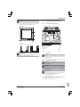
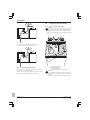
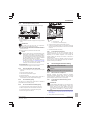
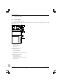
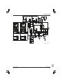
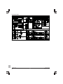
Installation manual Daikin Altherma ground source heat pump EGSQH10S18AA9W Installation manual Daikin Altherma ground source heat pump English CE DECLARACIONDECONFORMIDAD CE DICHIARAZIONEDICONFORMITA CE ΔHΛΩΣΗ ΣΥΜΜΟΡΦΩΣΗΣ 10 11 12 13 14 15 16 17 02 Hinweis* 18 19 20 21 22 23 24 25 în urma prevederilor: ob upoštevanju določb: vastavalt nõuetele: следвайки клаузите на: laikantis nuostatų, pateikiamų: ievērojot prasības, kas noteiktas: održiavajúc ustanovenia: bunun koşullarına uygun olarak: CE ERKLÆRING OMSAMSVAR CE ILMOITUSYHDENMUKAISUUDESTA CE PROHLÁŠENÍOSHODĚ JeanPierre Beuselinck Director Ostend, 4th of November 2013 enligt <A> och godkänts av <B> enligt Certifikatet <C>. som det fremkommer i <A> og gjennom positiv bedømmelse av <B> ifølge Sertifikat <C>. jotka on esitetty asiakirjassa <A> ja jotka <B> on hyväksynyt Sertifikaatin <C> mukaisesti. jak bylo uvedeno v <A> a pozitivně zjištěno <B> v souladu s osvědčením <C>. kako je izloženo u <A> i pozitivno ocijenjeno od strane <B> prema Certifikatu <C>. * 16 Megjegyzés* a(z) <A> alapján, a(z) <B> igazolta a megfelelést, a(z) <C> tanúsítvány szerint. 17 Uwaga* zgodnie z dokumentacją <A>, pozytywną opinią <B> i Świadectwem <C>. 18 Notă* aşa cum este stabilit în <A> şi apreciat pozitiv de <B> în conformitate cu Certificatul <C>. 19 Opomba* kot je določeno v <A> in odobreno s strani <B> v skladu s certifikatom <C>. 20 Märkus* nagu on näidatud dokumendis <A> ja heaks kiidetud <B> järgi vastavalt sertifikaadile <C>. Low Voltage 2006/95/EC Electromagnetic Compatibility 2004/108/EC 01 02 03 04 05 06 07 08 09 CE ATITIKTIESDEKLARACIJA CE ATBILSTĪBASDEKLARĀCIJA CE VYHLÁSENIEZHODY CE UYGUNLUKBEYANI Directives, as amended. Direktiven, gemäß Änderung. Directives, telles que modifiées. Richtlijnen, zoals geamendeerd. Directivas, según lo enmendado. Direttive, come da modifica. Οδηγιών, όπως έχουν τροποποιηθεί. Directivas, conforme alteração em. Директив со всеми поправками. 14 15 16 17 10 11 12 13 Directivelor, cu amendamentele respective. Direktive z vsemi spremembami. Direktiivid koos muudatustega. Директиви, с техните изменения. Direktyvose su papildymais. Direktīvās un to papildinājumos. Smernice, v platnom znení. Değiştirilmiş halleriyle Yönetmelikler. 2082543.0551QUA/EMC DEKRA (NB0344) DAIKIN.TCF.025E19/072013 Direktiver, med senere ændringer. 18 Direktiv, med företagna ändringar. 19 Direktiver, med foretatte endringer. 20 Direktiivejä, sellaisina kuin ne ovat 21 muutettuina. 22 v platném znění. 23 Smjernice, kako je izmijenjeno. 24 irányelv(ek) és módosításaik rendelkezéseit. 25 z późniejszymi poprawkami. 16 megfelelnek az alábbi szabvány(ok)nak vagy egyéb irányadó dokumentum(ok)nak, ha azokat előírás szerint használják: 17 spełniają wymogi następujących norm i innych dokumentów normalizacyjnych, pod warunkiem że używane są zgodnie z naszymi instrukcjami: 18 sunt în conformitate cu următorul (următoarele) standard(e) sau alt(e) document(e) normativ(e), cu condiţia ca acestea să fie utilizate în conformitate cu instrucţiunile noastre: 19 skladni z naslednjimi standardi in drugimi normativi, pod pogojem, da se uporabljajo v skladu z našimi navodili: 20 on vastavuses järgmis(t)e standardi(te)ga või teiste normatiivsete dokumentidega, kui neid kasutatakse vastavalt meie juhenditele: 21 съответстват на следните стандарти или други нормативни документи, при условие, че се използват съгласно нашите инструкции: 22 atitinka žemiau nurodytus standartus ir (arba) kitus norminius dokumentus su sąlyga, kad yra naudojami pagal mūsų nurodymus: 23 tad, ja lietoti atbilstoši ražotāja norādījumiem, atbilst sekojošiem standartiem un citiem normatīviem dokumentiem: 24 sú v zhode s nasledovnou(ými) normou(ami) alebo iným(i) normatívnym(i) dokumentom(ami), za predpokladu, že sa používajú v súlade s našim návodom: 25 ürünün, talimatlarımıza göre kullanılması koşuluyla aşağıdaki standartlar ve norm belirten belgelerle uyumludur: deklaruje na własną i wyłączną odpowiedzialność, że urządzenia, których ta deklaracja dotyczy: declară pe proprie răspundere că echipamentele la care se referă această declaraţie: z vso odgovornostjo izjavlja, da je oprema naprav, na katero se izjava nanaša: kinnitab oma täielikul vastutusel, et käesoleva deklaratsiooni alla kuuluv varustus: декларира на своя отговорност, че оборудването, за коeто се отнася тази декларация: visiška savo atsakomybe skelbia, kad įranga, kuriai taikoma ši deklaracija: ar pilnu atbildību apliecina, ka tālāk aprakstītās iekārtas, uz kurām attiecas šī deklarācija: vyhlasuje na vlastnú zodpovednosť, že zariadenie, na ktoré sa vzťahuje toto vyhlásenie: tamamen kendi sorumlulu*unda olmak üzere bu bildirinin ilgili oldu*u donanımının aşa*ıdaki gibi oldu*unu beyan eder: CE IZJAVA O SKLADNOSTI CE VASTAVUSDEKLARATSIOON CE ДЕКЛАРАЦИЯЗАСЪОТВЕТСТВИЕ 21 Забележка* както е изложено в <A> и оценено положително от <B> съгласно Сертификата <C>. <A> 22 Pastaba* kaip nustatyta <A> ir kaip teigiamai nuspręsta <B> pagal Sertifikatą <C>. <B> 23 Piezīmes* kā norādīts <A> un atbilstoši <B> pozitīvajam vērtējumam saskaņā ar sertifikātu <C>. <C> 24 Poznámka* ako bolo uvedené v <A> a pozitívne zistené <B> v súlade s osvedčením <C>. 25 Not* <A>’da belirtildiği gibi ve <C> Sertifikasına göre <B> tarafından olumlu olarak değerlendirildiği gibi. 08 estão em conformidade com a(s) seguinte(s) norma(s) ou outro(s) documento(s) normativo(s), desde que estes sejam utilizados de acordo com as nossas instruções: 09 соответствуют следующим стандартам или другим нормативным документам, при условии их использования согласно нашим инструкциям: 10 overholder følgende standard(er) eller andet/andre retningsgivende dokument(er), forudsat at disse anvendes i henhold til vore instrukser: 11 respektive utrustning är utförd i överensstämmelse med och följer följande standard(er) eller andra normgivande dokument, under förutsättning att användning sker i överensstämmelse med våra instruktioner: 12 respektive utstyr er i overensstemmelse med følgende standard(er) eller andre normgivende dokument(er), under forutssetning av at disse brukes i henhold til våre instrukser: 13 vastaavat seuraavien standardien ja muiden ohjeellisten dokumenttien vaatimuksia edellyttäen, että niitä käytetään ohjeidemme mukaisesti: 14 za předpokladu, že jsou využívány v souladu s našimi pokyny, odpovídají následujícím normám nebo normativním dokumentům: 15 u skladu sa slijedećim standardom(ima) ili drugim normativnim dokumentom(ima), uz uvjet da se oni koriste u skladu s našim uputama: 17 18 19 20 21 22 23 24 25 CE IZJAVAOUSKLAĐENOSTI CE MEGFELELŐSÉGINYILATKOZAT CE DEKLARACJAZGODNOŚCI CE DECLARAŢIEDECONFORMITATE заявляет, исключительно под свою ответственность, что оборудование, к которому относится настоящее заявление: erklærer under eneansvarlig, at udstyret, som er omfattet af denne erklæring: deklarerar i egenskap av huvudansvarig, att utrustningen som berörs av denna deklaration innebär att: erklærer et fullstendig ansvar for at det utstyr som berøres av denne deklarasjon innebærer at: ilmoittaa yksinomaan omalla vastuullaan, että tämän ilmoituksen tarkoittamat laitteet: prohlašuje ve své plné odpovědnosti, že zařízení, k němuž se toto prohlášení vztahuje: izjavljuje pod isključivo vlastitom odgovornošću da oprema na koju se ova izjava odnosi: teljes felelőssége tudatában kijelenti, hogy a berendezések, melyekre e nyilatkozat vonatkozik: delineato nel <A> e giudicato positivamente da <B> 11 Information* secondo il Certificato <C>. 12 Merk* όπως καθορίζεται στο <A> και κρίνεται θετικά από το <B> σύμφωνα με το Πιστοποιητικό <C>. 08 Nota* 13 Huom* tal como estabelecido em <A> e com o parecer positivo de <B> de acordo com o Certificado <C>. 09 Примечание* как указано в <A> и в соответствии 14 Poznámka* с положительным решением <B> согласно 15 Napomena* Свидетельству <C>. 10 Bemærk* som anført i <A> og positivt vurderet af <B> i henhold til Certifikat <C>. 07 Σημείωση* 06 Nota* under iagttagelse af bestemmelserne i: enligt villkoren i: gitt i henhold til bestemmelsene i: noudattaen määräyksiä: za dodržení ustanovení předpisu: prema odredbama: követi a(z): zgodnie z postanowieniami Dyrektyw: as set out in <A> and judged positively by <B> according to the Certificate <C>. wie in <A> aufgeführt und von <B> positiv beurteilt gemäß Zertifikat <C>. 03 Remarque* tel que défini dans <A> et évalué positivement par <B> conformément au Certificat <C>. 04 Bemerk* zoals vermeld in <A> en positief beoordeeld door <B> overeenkomstig Certificaat <C>. 05 Nota* como se establece en <A> y es valorado positivamente por <B> de acuerdo con el Certificado <C>. following the provisions of: gemäß den Vorschriften der: conformément aux stipulations des: overeenkomstig de bepalingen van: siguiendo las disposiciones de: secondo le prescrizioni per: με τήρηση των διατάξεων των: de acordo com o previsto em: в соответствии с положениями: 01 Note* 01 02 03 04 05 06 07 08 09 EN60335240, 01 are in conformity with the following standard(s) or other normative document(s), provided that these are used in accordance with our instructions: 02 der/den folgenden Norm(en) oder einem anderen Normdokument oder dokumenten entspricht/entsprechen, unter der Voraussetzung, daß sie gemäß unseren Anweisungen eingesetzt werden: 03 sont conformes à la/aux norme(s) ou autre(s) document(s) normatif(s), pour autant qu'ils soient utilisés conformément à nos instructions: 04 conform de volgende norm(en) of één of meer andere bindende documenten zijn, op voorwaarde dat ze worden gebruikt overeenkomstig onze instructies: 05 están en conformidad con la(s) siguiente(s) norma(s) u otro(s) documento(s) normativo(s), siempre que sean utilizados de acuerdo con nuestras instrucciones: 06 sono conformi al(i) seguente(i) standard(s) o altro(i) documento(i) a carattere normativo, a patto che vengano usati in conformità alle nostre istruzioni: 07 είναι σύμφωνα με το(α) ακόλουθο(α) πρότυπο(α) ή άλλο έγγραφο(α) κανονισμών, υπό την προϋπόθεση ότι χρησιμοποιούνται σύμφωνα με τις οδηγίες μας: 09 10 11 12 13 14 15 16 CE DECLARAÇÃODECONFORMIDADE CE ЗАЯВЛЕНИЕОСООТВЕТСТВИИ CE OVERENSSTEMMELSESERKLÆRING CE FÖRSÄKRANOMÖVERENSTÄMMELSE declares under its sole responsibility that the equipment to which this declaration relates: erklärt auf seine alleinige Verantwortung daß die Ausrüstung für die diese Erklärung bestimmt ist: déclare sous sa seule responsabilité que l'équipement visé par la présente déclaration: verklaart hierbij op eigen exclusieve verantwoordelijkheid dat de apparatuur waarop deze verklaring betrekking heeft: declara bajo su única responsabilidad que el equipo al que hace referencia la declaración: dichiara sotto la propria responsabilità che gli apparecchi a cui è riferita questa dichiarazione: δηλώνει με αποκλειστική της ευθύνη ότι ο εξοπλισμός στον οποίο αναφέρεται η παρούσα δήλωση: declara sob sua exclusiva responsabilidade que os equipamentos a que esta declaração se refere: EGSQH10S18AA9W, 01 02 03 04 05 06 07 08 Daikin Europe N.V. CE DECLARATIONOFCONFORMITY CE KONFORMITÄTSERKLÄRUNG CE DECLARATIONDECONFORMITE CE CONFORMITEITSVERKLARING 3P3517511 Table of contents 6 Commissioning Table of contents 1 About the documentation 1.1 About this document.................................................................. 6.1 6.2 6.3 6.4 3 3 6.5 2 About the box 2.1 Indoor unit.................................................................................. 2.1.1 To remove the accessories from the indoor unit......... 3 Preparation 3.1 3.2 Preparing piping ........................................................................ 3.1.1 To check the water volume of the space heating circuit and brine circuit ................................................ Preparing electrical wiring ......................................................... 3.2.1 Overview of electrical connections for external and internal actuators ........................................................ 4 Installation 4.1 4.2 4.3 4.4 4.5 4.6 Opening the units ...................................................................... 4.1.1 To open the indoor unit ............................................... 4.1.2 To open the switch box cover of the indoor unit ......... Mounting the indoor unit ............................................................ 4.2.1 To install the indoor unit.............................................. Connecting the brine piping....................................................... 4.3.1 To connect the brine piping......................................... 4.3.2 To fill the brine circuit .................................................. 4.3.3 To insulate the brine piping......................................... Connecting the water piping ...................................................... 4.4.1 To connect the water piping........................................ 4.4.2 To fill the space heating circuit.................................... 4.4.3 To fill the domestic hot water tank .............................. 4.4.4 To insulate the piping.................................................. 4.4.5 To connect the recirculation piping ............................. 4.4.6 To connect the drain hose .......................................... Connecting the electrical wiring................................................. 4.5.1 About electrical compliance ........................................ 4.5.2 To connect the electrical wiring on the indoor unit...... 4.5.3 To connect the main power supply ............................. 4.5.4 To connect the external temperature sensor .............. 4.5.5 To connect the user interface ..................................... 4.5.6 To connect the shutoff valve...................................... 4.5.7 To connect the electrical meters ................................. 4.5.8 To connect the domestic hot water pump ................... 4.5.9 To connect the alarm output ....................................... 4.5.10 To connect the space heating ON/OFF output ........... 4.5.11 To connect the changeover to external heat source... 4.5.12 To connect the power consumption digital inputs ....... Finishing the indoor unit installation .......................................... 4.6.1 To fix the user interface cover to the indoor unit......... 4.6.2 To close the indoor unit............................................... 5 Configuration 5.1 5.2 5.3 5.4 Overview: Configuration ............................................................ To modify an overview setting .................................... Basic configuration .................................................................... 5.2.1 Quick wizard: Language / time and date..................... 5.2.2 Quick wizard: Standard............................................... 5.2.3 Quick wizard: Options ................................................. 5.2.4 Quick wizard: Capacities (energy metering) ............... 5.2.5 Space heating control ................................................. 5.2.6 Domestic hot water control ......................................... 5.2.7 Contact/helpdesk number ........................................... Advanced configuration/optimization......................................... 5.3.1 Heat source settings ................................................... Menu structure: Overview installer settings............................... EGSQH10S18AA9W Daikin Altherma ground source heat pump 4P3517471B – 2013.12 4 4 4 4 22 Checklist before test run............................................................ To perform an air purge............................................................. To perform a test run ................................................................. To perform an actuator test run ................................................. 6.4.1 Possible actuator test runs.......................................... To perform an underfloor heating screed dryout ....................... 7 Handover to the user 7.1 23 To fix the applicable language on the unit name plate .............. 23 8 Technical data 8.1 4 22 22 22 22 22 23 24 Wiring diagram .......................................................................... 24 8.1.1 Wiring diagram: Indoor unit......................................... 24 4 4 4 1 About the documentation 1.1 About this document 5 5 5 5 5 5 7 7 7 8 8 8 9 9 9 9 9 9 9 9 11 11 12 13 13 13 14 14 14 14 15 15 15 Target audience Authorised installers Documentation set This document is part of a documentation set. The complete set consists of: Document Contains… General Safety instructions that safety you must read before precautions installing Format Paper (in the box of the indoor unit) Indoor unit installation manual Installation instructions Installer reference guide Preparation of the installation, technical specifications, good practices, reference data, … Digital files on http:// www.daikineurope.com/ supportandmanuals/ productinformation/. Addendum book for optional equipment Additional info about how to install optional equipment Paper (in the box of the indoor unit) Digital files on http:// www.daikineurope.com/ supportandmanuals/ productinformation/. Latest revisions of the supplied documentation may be available on the regional Daikin website or via your dealer. 15 15 15 16 16 16 17 17 18 18 19 19 19 20 Installation manual 3 2 About the box 2 About the box 3 Preparation 2.1 Indoor unit 3.1 Preparing piping 2.1.1 To remove the accessories from the indoor unit 3.1.1 To check the water volume of the space heating circuit and brine circuit 1 Remove the screws at the top of the unit. Minimum water volume 2 Remove the top panel. Check that the total water volume per circuit in the installation is minimum 20 liter, the internal water volume of the indoor unit NOT included. 4x INFORMATION In critical processes, or in rooms with a high heat load, extra water might be required. NOTICE When circulation in each space heating loop is controlled by remotely controlled valves, it is important that the minimum water volume is guaranteed, even if all of the valves are closed. 3.2 Preparing electrical wiring 3.2.1 Overview of electrical connections for external and internal actuators Item 3 b 1x c 1x e d 1x f 1x 1x Wires Maximum running current Indoor unit power supply Remove the accessories. a Description 1 Power supply for E1 and E3 3+N + GND (a) 2 Power supply for E2 2 (c) 4 Preferential kWh rate power supply (voltage free contact) 2 (d) 5 Normal kWh rate power 2 supply 1x g 1x 6.3 A User interface 6 a b c d e f g 4 General safety precautions Addendum book for optional equipment Installation manual Operation manual Remote outdoor sensor User interface kit cover Multilingual fluorinated greenhouse gases label Reinstall the top panel. User interface 2 (e) Optional equipment 12 Room thermostat 3 or 4 100 mA(b) 13 Outdoor ambient temperature sensor 2 (b) 14 Indoor ambient temperature sensor 2 (b) 15 Heat pump convector 4 100 mA(b) Field supplied components Installation manual 4 16 Shutoff valve 2 100 mA(b) 17 Electricity meter 2 (per meter) (b) 18 Domestic hot water pump 2 (b) 19 Alarm output 2 (b) 20 Changeover to external 2 heat source control (b) 22 Power consumption digital inputs (b) 2 (per input signal) EGSQH10S18AA9W Daikin Altherma ground source heat pump 4P3517471B – 2013.12 4 Installation (a) (b) (c) (d) (e) Refer to name plate on unit. Minimum cable section 0.75 mm². Cable section 2.5 mm². Cable section 0.75 mm² till 1.25 mm²; maximum length: 50 m. Voltagefree contact shall ensure the minimum applicable load of 15 V DC, 10 mA. Cable section 0.75 mm² till 1.25 mm²; maximum length: 500 m. Applicable for both single user interface and dual use interface connection. 4.1.2 To open the switch box cover of the indoor unit NOTICE More technical specifications of the different connections are indicated on the inside of the indoor unit. 4 Installation 4.1 Opening the units 4.1.1 To open the indoor unit 1 Loosen and remove the screws at the bottom of the unit. 2 Slide the front panel of the unit downwards and remove it. 7x CAUTION The front panel is heavy. Be careful NOT to jam your fingers when opening or closing the unit. 3 Loosen and remove the 4 screws that fix the top panel. 4 Remove the top panel from the unit. 3 4x 4 4.2 Mounting the indoor unit 4.2.1 To install the indoor unit 1 Bring the unit on the pallet as close as possible to its installation place. 2 Lift the indoor unit from the pallet and place it on the floor. 4x 1 2 210kg 2 1 2x EGSQH10S18AA9W Daikin Altherma ground source heat pump 4P3517471B – 2013.12 3 Slide the indoor unit into position. Make sure that the side support bolts are present when handling the unit. Installation manual 5 4 Installation 4 Unlink the heat pump module from the outer frame. ONLY remove the side support bolts! 2x NOTICE Do NOT throw away any bolts. They need to be reinserted when transport or heavy manipulation is required. 6 Adjust the height of the 4 leveling feet of the outer frame to compensate for floor irregularities. The maximum allowed deviation is 1°. ≤1° 5 Open the front plate of the unit. If needed, the nylon bands for lifting can be used. NOTICE For optimum sound reduction, carefully check if there is no gap between the bottom frame and the floor. 7 Adjust the height of the 2 front leveling feet of the inner frame to compensate for irregularities. CAUTION Check that the heat pump module does NOT touch the outer casing. Installation manual 6 EGSQH10S18AA9W Daikin Altherma ground source heat pump 4P3517471B – 2013.12 4 Installation NOTICE 4.3 Connecting the brine piping Check if the front support bolts remain levelled and are NOT stressed. The support feet from outer (b) and inner frame (c) MUST be adjusted so that those front bolts remain level. Do NOT adjust support foot (a)! 4.3.1 To connect the brine piping a b Bottom view: c b a Side view: a b INFORMATION To check if the front support bolts are not stressed, loosen them partly and fix them again afterwards. Brine out Brine in NOTICE To facilitate service and maintenance, it is recommended to install shutoff valves as close as possible to the inlet and outlet of the unit. 4.3.2 To fill the brine circuit WARNING Before, during and after filling carefully check the brine circuit for leakage. WARNING Temperature of the fluid running through the evaporator can become negative. It MUST be protected against freezing. Refer to setting [A04] in "5.2.2 Quick wizard: Standard" on page 16. INFORMATION The materials used in the units brine circuit are chemically resistant to the following antifreeze fluids: ▪ 40 mass% propylene glycol ▪ 29 mass% ethanol EGSQH10S18AA9W Daikin Altherma ground source heat pump 4P3517471B – 2013.12 1 Connect the unit to the field supplied brine filling system. 2 Position the 3way valve correctly. Installation manual 7 4 Installation 4.4 Connecting the water piping 4.4.1 To connect the water piping NOTICE Do NOT use excessive force when connecting the piping. Deformation of the piping can cause malfunctioning of the unit. 1 Connect the domestic hot water in and out pipes to the indoor unit. a 3 Fill the circuit. 4 Purge as much air as possible from the brine circuit. 5 Return the 3way valve to its original position. 4.3.3 a b c d To insulate the brine piping The piping in the complete brine circuit MUST be insulated to prevent reduction of the heating capacity. b Space heating water out Space heating water in Domestic hot water out Domestic cold water in (cold water supply) It is recommended to install shutoff valves to cold water in and hot water out connections. Shutoff valves are field supplied. 2 8 d NOTICE Consider that the brine circuit piping inside the house can/will condensate. Foresee adequate insulation for these pipes. Installation manual c Connect the space heating in and out pipes to the indoor unit. EGSQH10S18AA9W Daikin Altherma ground source heat pump 4P3517471B – 2013.12 4 Installation 4.4.2 1 To fill the space heating circuit a Connect the water supply hose to the fill valve (field supply). b 2 Open the fill valve. 3 Make sure that the automatic air purge valve is open (at least 2 turns). INFORMATION For location of the air purge valve, see Components: Indoor unit in the Installer reference guide. 4 Fill the circuit with water until the manometer indicates a pressure of ±2.0 bar. 5 Purge as much air as possible from the water circuit. NOTICE ▪ Air in the water circuit can cause malfunctioning of the backup heater. During filling, it may not be possible to remove all the air from the circuit. Remaining air will be removed through the automatic air purge valves during the initial operating hours of the system. Additional filling with water afterwards may be required. ▪ To purge the system, use the special function as described in the chapter "6 Commissioning" on page 22. This function should be used to purge the heat exchanger coil of the domestic hot water tank. 6 Close the fill valve. 7 Disconnect the water supply hose from the fill valve. 4.4.3 Open every hot water tap in turn to purge air from the system pipe work. 2 Open the cold water supply valve. 3 Close all water taps after all air is purged. 4 Check for water leaks. 5 Manually operate the field installed pressure relief valve to ensure that free water flow through the discharge pipe. To insulate the piping Remove the knockout hole at the backside of the unit. 6 Connect the recirculation piping to the recirculation connection and route the piping through the knockout hole at the backside of the unit. 7 Reattach the insulation and casing. 4.4.6 The drain hose is routed to the backside on the left, close to the bottom of the unit. A field supplied drain pump might be needed to pump the water away to the field drain. 4.5 Connecting the electrical wiring DANGER: RISK OF ELECTROCUTION WARNING ALWAYS use multicore cable for power supply cables. 4.5.1 Loosen and remove the screws at the bottom of the unit. 2 Slide the front panel of the unit downwards and remove it. 3 Loosen and remove the 4 screws that fix the top panel. 4 Remove the top panel from the unit. EGSQH10S18AA9W Daikin Altherma ground source heat pump 4P3517471B – 2013.12 About electrical compliance Equipment complying with EN/IEC 61000312 (European/ International Technical Standard setting the limits for harmonic currents produced by equipment connected to public lowvoltage systems with input current >16 A and ≤75 A per phase.). 4.5.2 To connect the electrical wiring on the indoor unit INFORMATION Foresee additional cable length of 35 cm for all wires which should be connected to X2M and X5M on sheet metal support above the hydro PCB. Additional wire length should be tie wrapped at the back side of the unit. Reason is to guarantee serviceability of, for example, the hydro PCB. To connect the recirculation piping 1 To connect the drain hose Condensate can form on the brine components inside the compressor department of the unit. The unit contains a drain pan. Depending on room ambient temperature, room humidity and operation condition, the drain pan can overflow. A drain hose is supplied with the unit. The piping in the complete brine circuit MUST be insulated to prevent reduction of the heating capacity. 4.4.5 Knockout hole Connection for recirculation piping 5 To fill the domestic hot water tank 1 4.4.4 a b 1 To open the indoor unit, see "4.1.1 To open the indoor unit" on page 5 and "4.1.2 To open the switch box cover of the indoor unit" on page 5. 2 Wiring should enter the unit from the top: Installation manual 9 4 Installation a c b c a 3 Routing of the wiring inside the unit should be as follows: a c b ≥50 mm a 1x 1x YC Y1 Y2 Y3 Y4 1x c X1 X2 X3 X4 1x X2M X5M 11 12 a c NOTICE ▪ Make sure that 50 mm is guaranteed between the low voltage (a) and high voltage (c) cables. ▪ Make sure that the cables (a) and (c) are routed between the wire guide and the backside of the switch box to prevent water ingress. 4 1x ≥50 mm 1x Fix the cable with cable ties to the cable tie mountings to ensure strain relief and to make sure that it does NOT come in contact with the piping and sharp edges. ≥50 mm Routing Possible cables (depending on unit type and installed options) a ▪ User interface Low voltage ▪ Power consumption digital inputs (field supply) ▪ Outdoor ambient temperature sensor ▪ Indoor ambient temperature sensor (option) ▪ Electrical meters (field supply) Installation manual 10 EGSQH10S18AA9W Daikin Altherma ground source heat pump 4P3517471B – 2013.12 4 Installation Routing Possible cables (depending on unit type and installed options) b ▪ Normal kWh rate power supply (power supply for unit) High voltage power supply c ▪ Preferential kWh rate power supply High voltage control signal ▪ Preferential power supply contact ▪ Heat pump convector (option) ▪ Room thermostat (option) ▪ Shutoff valve (field supply) ▪ Domestic hot water pump (field supply) ▪ Alarm output ▪ Changeover to external heat source control a b c CAUTION Do NOT push or place redundant cable length in the unit. 2 4.5.3 1 Fix the cable with cable ties to the cable tie mountings. To connect the main power supply INFORMATION Connect the main power supply. In case of preferential kWh rate power supply, the necessity of separate normal kWh rate power supply to indoor unit (b) X2M30/31 depends on the type of preferential kWh rate power supply. In case of normal kWh rate power supply X1A X19A Separate connection to the indoor unit is required: X2M X5M Main power supply Normal kWh rate power supply Preferential power supply contact 30 31 ▪ if preferential kWh rate power supply is interrupted when active, OR X6YB ▪ if no power consumption of the indoor unit is allowed at the preferential kWh rate power supply when active. X6Y X6YA a X1M 4.5.4 N L3 L2 L1 To connect the external temperature sensor If the desired leaving water temperature is weather dependent, the full time outdoor temperature measurement is important. This is possible via the external temperature sensor delivered as accessory. 1 Connect the external temperature sensor cable to the indoor unit. Legend: see illustration below. In case of preferential kWh rate power supply S1S N L c b X1A X19A X2M 34 X5M X5M 30 31 29 X2M 101112 34 X6Y X6YB X6YA X1M a 2 Fix the cable with cable ties to the cable tie mountings. 3 Install the external temperature sensor as described in the installation manual of the sensor. N L3 L2 L1 EGSQH10S18AA9W Daikin Altherma ground source heat pump 4P3517471B – 2013.12 Installation manual 11 4 Installation 4.5.5 1 To connect the user interface From the rear Connect the user interface cable to the indoor unit. PCB 1x a b a b 5 X5M X2M Reinstall the faceplate onto the wallplate. To fix the user interface to the wall in case of installation as room thermostat 1 12 2 Notch this part for the wiring to pass through with nippers etc. Secure the wiring to the front part of the casing using the wiring retainer and clamp. Insert a screwdriver into the slots underneath the user interface and carefully separate the faceplate from the wallplate. Fix the cable with cable ties to the cable tie mountings. To fix the user interface to the unit 1 Insert a screwdriver into the slots underneath the user interface and carefully separate the faceplate from the wallplate. NOTICE NOTICE The PCB is mounted in the faceplate of the user interface. Be careful NOT to damage it. 2 Fix the wallplate of the user interface to the wall. 3 Connect the wires to the user interface as shown below From the rear The PCB is mounted in the faceplate of the user interface. Be careful NOT to damage it. 2 Fix the wallplate of the user interface to the frontplate of the unit. PCB 1x a b From the left PCB 1x 3 Cut off a 2 wire conductor. 4 Connect the wires to the user interface as shown below. a b From the top a b PCB 1x b Installation manual 12 EGSQH10S18AA9W Daikin Altherma ground source heat pump 4P3517471B – 2013.12 4 Installation From the top center 4.5.7 a To connect the electrical meters INFORMATION b In case of an electrical meter with transistor output, check the polarity. The positive polarity MUST be connected to X5M/7 and X5M/9; the negative polarity to X5M/8 and X5M/10. PCB 1 Connect the electrical meters cable to the appropriate terminals as shown in the illustration below. S2S S3S 1x b a b 4 Reinstall the faceplate onto the wallplate. 4.5.6 1 Notch this part for the wiring to pass through with nippers etc. Secure the wiring to the front part of the casing using the wiring retainer and clamp. To connect the shutoff valve Connect the valve control cable to the appropriate terminals as shown in the illustration below. X5M NOTICE X2M 6 7 8910 Wiring is different for a NC (normal closed) valve and a NO (normal open) valve. M2S 2 M2S Fix the cable with cable ties to the cable tie mountings. 4.5.8 1 NO NC To connect the domestic hot water pump Connect the domestic hot water pump cable to the appropriate terminals as shown in the illustration below. M 1~ X5M X2M 5 67 2 X5M M2P X2M 5 67 Fix the cable with cable ties to the cable tie mountings. X5M X2M 34 35 2 EGSQH10S18AA9W Daikin Altherma ground source heat pump 4P3517471B – 2013.12 Fix the cable with cable ties to the cable tie mountings. Installation manual 13 4 Installation 4.5.9 1 To connect the alarm output Connect the alarm output cable to the appropriate terminals as shown in the illustration below. 4.5.11 1 To connect the changeover to external heat source Connect the changeover to external heat source cable to the appropriate terminals as shown in the illustration below. NL a A4P A4P X5M X2M 29 a 2 X2M Fix the cable with cable ties to the cable tie mountings. 4.5.10 1 X5M Installation of EKRP1HB is required. To connect the space heating ON/OFF output Connect the space heating ON/OFF output cable to the appropriate terminals as shown in the illustration below. a 2 Installation of EKRP1HB is required. Fix the cable with cable ties to the cable tie mountings. 4.5.12 1 To connect the power consumption digital inputs Connect the power consumption digital inputs cable to the appropriate terminals as shown in the illustration below. S6S S7S S8S S9S A4P a X5M X2M 1 23 4 5 29 a 2 Installation of EKRP1HB is required. A8P Fix the cable with cable ties to the cable tie mountings. X5M a 2 Installation manual 14 X2M Installation of EKRP1AHTA is required. Fix the cable with cable ties to the cable tie mountings. EGSQH10S18AA9W Daikin Altherma ground source heat pump 4P3517471B – 2013.12 5 Configuration 4.6 Finishing the indoor unit installation Legend for the settings tables: ▪ #: Breadcrumb in the menu structure ▪ Code: Code in the overview settings 4.6.1 To fix the user interface cover to the indoor unit 1 Make sure that the front panel is removed from the indoor unit. See "4.1.1 To open the indoor unit" on page 5. 2 Plug the user interface cover into the hinges. When the installer settings are changed, the system will request to confirm. When confirmation is complete, the screen will shortly turn OFF and "busy" will be displayed for several seconds. The most commonly used installation settings are accessible through the menu structure. Their location is mentioned by the breadcrumb indication (#). Additionally, all installer settings can also be found in "5.4 Menu structure: Overview installer settings" on page 20. For access to the setting codes, see " To access the installer settings" on page 15. Not all settings are accessible through the menu structure. Some are only accessible through their code. Then in the table explained below, the bread crumb is set as N/A (not applicable). To access the installer settings 1 Set the user permission level to Installer. 2 Go to [A]: > Installer settings. To access the overview settings 3 Mount the front panel to the indoor unit. 4.6.2 To close the indoor unit 1 Close the switch box cover. 2 Reinstall the top plate. 3 Reinstall the front panel. 1 Set the user permission level to Installer. 2 Go to [A.8]: To set the user permission level to Installer 1 Go to [6.4]: 2 Press 5 Configuration 5.1 Overview: Configuration If you do NOT press any button for more than 1 hour or press again for more than 4 seconds, the installer permission level switches back to End user. To switch between user permission levels (End user and Advanced end user) 1 Go to [6] or any of its submenus: 2 Press > Information. for more than 4 seconds. Result: The user permission level switches to Adv. end user. Additional information is displayed and "+" is added to the menu title. 3 If you do NOT configure the system correctly, it might NOT work as expected. You can configure the system with the user interface. > Information > User permission level. for more than 4 seconds. Result: is displayed on the home pages. 3 NOTICE When closing the indoor unit cover, make sure that the tightening torque does NOT exceed 4.1 N•m. > Installer settings > Overview settings. If you do NOT press any button for more than 1 hour or press again for more than 4 seconds, the user permission level switches back to End user. To modify an overview setting Example: Modify [101] from 15 to 20. When you turn ON the user interface for the first time (via the indoor unit), a quick wizard starts to help you configure the system. If necessary, you can also make changes to the configuration afterwards. NOTICE The explanation about the configuration in this chapter gives you ONLY basic explanations. For more detailed explanation and background information, see the installer reference guide. The configuration influences the following: ▪ The calculations of the software ▪ What you can see on and do with the user interface 1 Go to [A.8]: 2 Go to the corresponding screen of the first part of the setting by using the and button. INFORMATION An additional 0digit is added to the first part of the setting when you access the codes in the overview settings. Example: [101]: "1" will result in "01". Overview settings 01 00 00 01 15 02 00 03 00 04 05 06 07 08 09 0a 0b 0c 0d 0e 0f Confirm EGSQH10S18AA9W Daikin Altherma ground source heat pump 4P3517471B – 2013.12 > Installer settings > Overview settings. Adjust Scroll Installation manual 15 5 Configuration 3 Go to the corresponding second part of the setting by using the and button. # Code [A.2.1.B] N/A Overview settings 00 00 01 04 05 08 09 0c 0d User interface location: 01 15 02 00 03 00 06 07 0a 0b 0e 0f Confirm Adjust Description Only if there are 2 user interfaces: ▪ 0 (At unit) ▪ 1 (In room)(default) [A.2.1.8] [702] Number of water temperature zones: ▪ 0 (1 LWT zone): Main Scroll ▪ 1 (2 LWT zones): Main + additional Result: The value to be modified is now highlighted. 4 Modify the value by using the and [A.2.1.9] [F0D] button. ▪ 0 (Continuous): Continuous pump operation, regardless of thermo ON or OFF condition. Overview settings 01 00 00 01 20 02 00 03 00 04 05 06 07 08 09 0a 0b 0c 0d 0e 0f Confirm Adjust ▪ 1 (Sample)(default): When thermo OFF condition occurs, the pump runs every 5 minutes and the water temperature is checked. If the water temperature is below target, unit operation can start. Scroll 5 Push to confirm the modification of the parameter. 6 Repeat previous steps if you have to modify other settings. 7 Push the 8 Confirm by pressing or Pump operation: ▪ 2 (Request): Pump operation based on request. Example: Using a room thermostat and thermostat creates thermo ON/OFF condition. button to leave the overview settings menu. . Brine freezing temperature Installer settings The system will restart. # [A.6.9] Code [A04] Description Brine freezeup temp ▪ 0: 0°C OK Cancel Confirm ▪ 1: –2°C Adjust ▪ 2: –4°C ▪ 3: –6°C 5.2 Basic configuration 5.2.1 Quick wizard: Language / time and date ▪ 4: –8°C ▪ 5: –10°C # Code ▪ 7 (default): –14°C Description [A.1] N/A Language [1] N/A Time and date 5.2.2 ▪ 6: –12°C NOTICE The setting brine freezing temperature can be modified and the read out is correct in [A.6.9] Brine freezeup temp ONLY after having accessed menu [A.8] Overview settings. Quick wizard: Standard Backup heater configuration # [A.2.1.5] Code [50D] This setting can ONLY be modified and/or saved and the read out is ONLY correct if the communication between hydro module and compressor module is present. The communication between hydro module and compressor module is NOT guaranteed and/or applicable if: Description BUH type: ▪ 4 (3PN,(1/2)): 6 kW 3N~ 400 V Space heating settings # [A.2.1.7] Code [C07] ▪ error "U4" appears on the user interface, ▪ 0 (LWT control)(default): Unit operation is decided based on the leaving water temperature. Capacity boost ▪ 1 (Ext RT control): Unit operation is decided by the external thermostat. N/A ▪ 2 (RT control): Unit operation is decided based on the ambient temperature of the user interface. Installation manual 16 ▪ the heat pump module is connected to preferential kWh rate power supply where power supply is interrupted and preferential kWh rate power supply is activated. Description Unit temperature control: # Code [A03] Description Compressor frequency ▪ 0 (default): normal ▪ 1: boost EGSQH10S18AA9W Daikin Altherma ground source heat pump 4P3517471B – 2013.12 5 Configuration 5.2.3 Digital I/O PCB Quick wizard: Options # Domestic hot water settings # Code N/A [E05] [A.2.2.6.1] Description External backup heater source: ▪ 1 (Bivalent): Gas, oil boiler [A.2.2.6.3] [C09] Alarm output on optional EKRP1HB PCB: DHW pump: ▪ 0 (Normally open)(default): The alarm output will be powered when an alarm occurs. ▪ 0 (No)(default): NOT installed ▪ 1 (Secondary rtrn): Installed for instant hot water ▪ 2 (Disinf. disinfection shunt): Installed ▪ 1 (Normally closed): The alarm output will NOT be powered when an alarm occurs. This installer setting allows distinction between detection of an alarm and detection of a power failure to the unit. for See also illustrations below. Domestic hot water pump installed for… Instant hot water See also table below (Alarm output logic). Disinfection c a c a f b Alarm output logic d f e g [C09] b g a b c d e f g Indoor unit Tank Domestic hot water pump Heater element Nonreturn valve Shower Cold water Alarm # Code [C05] Closed output Open output 1 Open output Closed output [C06] [C08] Open output Demand PCB # [A.2.2.7] Code [D04] Description Description Demand PCB ▪ 0 (No)(default): NOT installed External room thermostat for the main zone: ▪ 1 (Yes): Installed Energy metering # [A.2.2.8] Code [D08] ▪ 1: Installed (0.1 pulse/kWh) ▪ 2: Installed (1 pulse/kWh) ▪ 3: Installed (10 pulse/kWh) ▪ 4: Installed (100 pulse/kWh) External sensor: ▪ 0 (No)(default): NOT installed. Description Optional external kWh meter 1: ▪ 0 (No): NOT installed External room thermostat for the additional zone: ▪ 1 (Thermo ON/OFF): When the used external room thermostat or heat pump convector can only send a thermo ON/OFF condition. [A.2.2.B] No power supply to unit Indicates if the optional demand PCB is installed. ▪ 1 (Thermo ON/OFF): When the used external room thermostat or heat pump convector can only send a thermo ON/OFF condition. [A.2.2.5] No alarm 0 (default) Thermostats and external sensors [A.2.2.4] Description ▪ 0 (No)(default): None ▪ 1 (Yes): Installed [D02] [C02] DHW operation: ▪ 0: N/A [A.2.2.A] Code ▪ 5: Installed (1000 pulse/kWh) [A.2.2.9] [D09] Optional external kWh meter 2: ▪ 0 (No): NOT installed ▪ 2 (Room sensor): Connected to PCB measuring the indoor temperature. ▪ 1: Installed (0.1 pulse/kWh) ▪ 2: Installed (1 pulse/kWh) ▪ 3: Installed (10 pulse/kWh) ▪ 4: Installed (100 pulse/kWh) ▪ 5: Installed (1000 pulse/kWh) 5.2.4 # EGSQH10S18AA9W Daikin Altherma ground source heat pump 4P3517471B – 2013.12 Quick wizard: Capacities (energy metering) Code Description [A.2.3.2] [603] Capacity of the first step of the backup heater at nominal voltage [kW] [A.2.3.3] [604] Capacity difference between the second and first step of the backup heater [kW] Installation manual 17 5 Configuration 5.2.5 Leaving water temperature: Delta T emitter Space heating control # Leaving water temperature: Main zone # [A.3.1.1.1] Code N/A [A.3.1.3.1] Description Code [909] Set point mode: dep.): Weather ▪ 2 (Fixed/scheduled): Absolute + scheduled (only for leaving water temperature control) ▪ 3 (WD/scheduled): Weather dependent + scheduled (only for leaving water temperature control) [A.3.1.1.3] [100] [101] Leaving water temperature: Modulation # [A.3.1.1.5] Code [805] ▪ 0 (No): Disabled Weatherdependent curve (heating): Tt [1-02] [1-03] [1-00] [1-01] Ta ▪ Tt: Target leaving water temperature (main) Leaving water temperature: Emitter type # [A.3.1.1.7] Code [90B] ▪ Ta: Outdoor temperature # Code N/A Description ▪ 1 (Slow) Example: Large water volume, floor heating loops. Set point mode: ▪ 0 (Fixed): Absolute ▪ 1 (Weather Weatherdependent Depending on the system water volume and the heat emitters type, the heat up of a space can take longer. This setting can compensate for a slow or a quick heating system by adjusting the unit capacity during the heat up cycle. dep.): ▪ 2 (Fixed/scheduled): Absolute + scheduled (only for leaving water temperature control) ▪ 3 (WD/scheduled): Weather dependent + scheduled (only for leaving water temperature control) [A.3.1.2.3] [000] [001] Weatherdependent curve (heating): 5.2.6 # Tt [A.4.1] Domestic hot water control Code [60D] Description Domestic hot water Type: ▪ 0 (Reheat only): Only reheat operation is allowed. [002] [003] Description Reaction time of the system: ▪ 0 (Quick)(default) Example: Small water volume and fan coils. Leaving water temperature: Additional zone [A.3.1.2.1] Description Leaving water temperature modulation: ▪ 1 (Yes): Enabled. The leaving water temperature is calculated according to the difference between desired and actual room temperature. This allows better matching of the heat pump capacity to actual required capacity and results in less start/stop cycles of the heat pump and more economic operation. [102] [103] Heating: required temperature difference between entering and leaving water. In case a minimum temperature difference is required for the good operation of the heat emitters in heating mode. ▪ 0 (Fixed): Absolute ▪ 1 (Weather dependent Description [0-01] ▪ 1 (Reheat + sched.)(default): Same as 2, but between the scheduled heatup cycles, reheat operation is allowed. [0-00] [0-03] [0-02] ▪ Tt: Target leaving water temperature (additional) ▪ Ta: Outdoor temperature ▪ 2 (Scheduled only): The domestic hot water tank can ONLY be heated according to a schedule. Ta [A.4.3.1] N/A How is the tank temperature to be displayed on the user interface? ▪ As temperature. 60°C ▪ As graphic: The temperature has to be displayed as available hot water for x persons. If you choose this, you also have to configure which number equals which temperature under [A.4.3.2.1]~[A.4.3.2.6]: 4 Installation manual 18 EGSQH10S18AA9W Daikin Altherma ground source heat pump 4P3517471B – 2013.12 5 Configuration # Code [A.4.5] [60E] Description The maximum temperature that users can select for the domestic hot water. You can use this setting to limit the temperature at the hot water taps. INFORMATION It is recommended NOT to use the selection of ([60D]=0, [A.4.1] Domestic hot water Type=Reheat only). The risk of space heating capacity shortage/comfort problems is significant (in case of frequent domestic hot water operation, frequent and long space heating interruption will happen). 5.2.7 Contact/helpdesk number # [6.3.2] Code N/A Description Number that users can call in case of problems. 5.3 Advanced configuration/ optimization 5.3.1 Heat source settings Auto emergency When the heat pump fails to operate the backup heater can serve as an emergency heater and either automatically or nonautomatically take over the heat load. When auto emergency is activated and a heat pump failure occurs, the backup heater will automatically take over the heat load. When a heat pump failure occurs and auto emergency is not activated, the domestic hot water and space heating operations will stop and need to be recovered manually. The user interface will then ask you to confirm whether the backup heater can take over the heat load or not. When the heat pump fails, will appear on the user interface. If the house is unattended for longer periods, we recommend that setting [A.5.1.2] Auto emergency operation shall be set to Automatic. # [A.5.1.2] Code N/A Description Defines whether in an emergency situation the backup heater is allowed to automatically take over the entire heat load or whether manual confirmation is required. ▪ 0: Manual (default) ▪ 1: Automatic EGSQH10S18AA9W Daikin Altherma ground source heat pump 4P3517471B – 2013.12 Installation manual 19 5 Configuration 5.4 Menu structure: Overview installer settings [A] Installer settings Language System layout Space operation Domestic hot water (DHW) Heat sources System operation Commissioning Overview settings [A.2] System layout Standard Options Capacities Confirm layout [A.2.1] Standard Unit type Compressor type Indoor software type BUH type Preferential kWh rate Unit control method Number of LWT zones Pump operation mode Power saving possible User interface location [A.2.2] Options [A.3] Space operation LWT settings Room thermostat Operation range Contact type main Contact type add. Digital I/O PCB Demand PCB External kWh meter 1 External kWh meter 2 DHW pump External sensor [A.3.1] LWT settings Main Additional Delta T emitter [A.3.2] Room thermostat Room temp. range Room temp. offset Room temp. step [A.4] Domestic hot water (DHW) Type Setpoint readout Disinfection Maximum setpoint SP mode Weather-dependent curve [A.3.3] Operation range Space heating OFF temp [A.4.3] Setpoint readout Setpoint readout type Conversion persons [A.2.2.6] Digital I/O PCB Alarm output Ext. backup heat src Solar kit [A.3.1.1] Main LWT setpoint mode Temperature range Set weather-dependent heating Modulated LWT Shut-off valve Emitter type [A.3.1.2] Additional LWT setpoint mode Temperature range Set weather-dependent heating [A.3.1.3] Delta T emitter Heating [A.4.4] Disinfection Disinfection Operation day Start time Temperature target Duration INFORMATION Forced defrost settings are shown but are NOT applicable for this unit. Settings shall NOT be used or changed. INFORMATION Solar kit settings are shown but are NOT applicable for this unit. Settings shall NOT be used or changed. Installation manual 20 EGSQH10S18AA9W Daikin Altherma ground source heat pump 4P3517471B – 2013.12 5 Configuration [A.5] Heat sources Backup heater [A.6] System operation Auto restart Preferential kWh rate Pwr consumpt. control Averaging time Ext amb. sensor offset Forced defrost Brine freezeup temp [A.7] Commissioning Test run UFH screed dryout Air purge Actuator test run [A.5.1] Backup heater Operation mode Auto emergency operation Enable BUH step 2 Equilibrium temp. [A.6.2] Preferential kWh rate Allowed heaters Forced pump OFF [A.6.3] Pwr consumpt. control Mode Type Amp. value kW value Amp. limits for DI kW limits for DI Priority [A.7.2] UFH screed dryout Set dryout schedule Start dryout Dryout status [A.7.3] Air purge Type Start air purge EGSQH10S18AA9W Daikin Altherma ground source heat pump 4P3517471B – 2013.12 Installation manual 21 6 Commissioning 6 6.1 Commissioning Checklist before test run Do NOT operate the system before the following checks are OK: The indoor unit is properly mounted. The following field wiring has been carried out according to this document and the applicable legislation: ▪ Between the local supply panel and the indoor unit 6.3 To perform a test run Prerequisite: Make sure the user interface shows the home screens and that the space heating and domestic hot water demands are turned off. 1 Go to [A.7.1]: run. > Installer settings > Commissioning > Test 2 Select a test and press 3 Select OK and press . Example: Heating. . Result: The test run starts. It stops automatically when done (±30 min). To stop it manually, press , select OK and press . INFORMATION ▪ Between the indoor unit and the valves (if applicable) If 2 user interfaces are present, you can start a test run from both user interfaces. ▪ Between the indoor unit and the room thermostat (if applicable) The system is properly earthed and the earth terminals are tightened. ▪ The user interface used to start the test run displays a status screen. The fuses or locally installed protection devices are installed according to this document, and have not been bypassed. ▪ The other user interface displays a "busy" screen. You cannot stop the test run as long as the "busy" screen is shown. The power supply voltage matches the voltage on the identification label of the unit. There are NO loose connections or damaged electrical components in the switch box. There are NO damaged components or squeezed pipes on the inside of the indoor unit. 6.4 To perform an actuator test run Prerequisite: Make sure the user interface shows the home screens and that the space heating and domestic hot water demands are turned off. 1 Make sure the room temperature control, the leaving water temperature control and the domestic hot water control are turned OFF via the user interface. The correct pipe size is installed and the pipes are properly insulated. 2 Go to [A.7.4]: Actuator test run. There is NO water and/or brine leak inside the indoor unit. 3 Select an actuator and press There are no odour traces noticeable of the used brine. 4 Select OK and press There are NO refrigerant leaks. The space heating air purge valve is open (at least 2 turns). > Installer settings > Commissioning > . Example: Pump. . Result: The actuator test run starts. It automatically stops when finished. To stop it manually, press , select OK and press . The pressure relief valves purge to a safe location when opened. 6.4.1 Possible actuator test runs NOTICE ▪ Backup heater (step 2) test NEVER operate the unit without thermistors, burning of the compressor may result. ▪ Pump test (space heating) ▪ Backup heater (step 1) test INFORMATION 6.2 To perform an air purge Prerequisite: Make sure the user interface shows the home screens and that the space heating and domestic hot water demands are turned off. 1 Go to [A.7.3]: purge. > Installer settings > Commissioning > Air 2 Set the type, speed and circuit. 3 Select Start air purge and press 4 Select OK and press 22 Make sure that air is purged before executing the test run. Also avoid causing disturbances in the water circuit during the test run. ▪ Brine pump test ▪ 2way valve test . . Result: The air purge starts. It stops automatically when done. To stop it manually, press , select OK and press . Installation manual Calibration of the produced heat calculation is included in this test. ▪ 3way valve test ▪ Bivalent signal test ▪ Alarm output test ▪ Circulation pump test EGSQH10S18AA9W Daikin Altherma ground source heat pump 4P3517471B – 2013.12 7 Handover to the user 6.5 To perform an underfloor heating screed dryout Prerequisite: Make sure the user interface shows the home screens and that the space heating and domestic hot water demands are turned off. 1 Go to [A.7.2]: screed dryout. > Installer settings > Commissioning > UFH 2 Set a dryout program. 3 Select Start dryout and press 4 Select OK and press . . Result: The underfloor heating screed dryout starts. It stops automatically when done. To stop it manually, press , select OK and press . 7 Handover to the user Once the test run is finished and the unit operates properly, please make sure the following is clear for the user: ▪ Fill in the installer setting table (in the operation manual) with the actual settings. ▪ Make sure that the user has the printed documentation and ask him/her to keep it for future reference. Inform the user that he can find the complete documentation on the url as earlier described in this manual. ▪ Explain the user how to properly operate the system and what he/ she has to do in case of problems. ▪ Show the user what he/she has to do in relation to maintaining the unit. ▪ Explain the user about energy saving tips as described in the operation manual. 7.1 To fix the applicable language on the unit name plate 1 From the multilingual fluorinated greenhouse gases label peal off the applicable language. 2 Stick it on top of the marked area on the unit name plate. EGSQH10S18AA9W Daikin Altherma ground source heat pump 4P3517471B – 2013.12 Installation manual 23 8 Technical data 8 Technical data 8.1 Wiring diagram 8.1.1 Wiring diagram: Indoor unit See the internal wiring diagram supplied with the unit (on the inside of the indoor unit switch box cover). The abbreviations used are listed below. Position in switch box A1P A8P X5M TR1 A4P K6M X2M K1M K2M K5M Q1L X6Y A9P F1B X1M A10P L3R L2R L1R User installed options: Remote user interface External indoor thermistor Digital I/O PCB Demand PCB Main leaving water temperature: On/OFF thermostat (wired) On/OFF thermostat (wireless) External thermistor on On/OFF thermostat (wireless) Heat pump convector Additional leaving water temperature: On/OFF thermostat (wired) On/OFF thermostat (wireless) External thermistor on On/OFF thermostat (wireless) Heat pump convector Installation manual 24 EGSQH10S18AA9W Daikin Altherma ground source heat pump 4P3517471B – 2013.12 8 Technical data L5R X2M 30 31 A9P.X803A.5 Only for normal power supply (standard) A9P.X803A.3 Q1L 12 A1 A2 X6YA 29 21 X6YB X6Y X6YA X6Y 1 X2M.28 X2M 11 TR1 X6YB 30 31 31 32 1 K5M X2M X2M.3 L5R Q2DI 1N~, 50 Hz 230 V AC Normal kWh rate power supply A9P.X803A.5 L N A9P.X803A.3 Only for preferential kWh rate power supply R1T R1T -t- 5 X2M 1 2 C COM H KPR X2M.4 A4P L N PC -t- X2M.3 X20A:1 3 5 X25A:1 2 3 4 X11M 5 6 X16A:5 3 1 X15A:1 3 K2R X11A:3 1 X12A:3 1 A1 A1 X2M.21 5 6 NO valve Add LWT zone 3 wire type (SPDT) M3S M1P MS 34 35 M M2P 1~ A2 K1M K2M DHW pump output Max. load: 2 A (inrush) - 230 V AC 1 A (continuous) DHW pump A3P Heatpump convector NC N GND N M2S X2M Switch box L X2M 5 6 7 A2 X2M.7 Main LWT zone X2M.4 X2M.5 A3P 2 PWM only for ext. sensor (floor or ambient) 3 Heatpump convector X28A:1 NO 6 5 6 3 5 K1R X2M.28 only for wireless On/OFF thermostat X2M.1a X2M.4 X2M.1 only for ext. sensor (floor or ambient) X2A:1 K6R R2T BLK BLU BRN -t- only for wireless On/OFF thermostat X11M A3P X1M R1T R1H -t%H20 R2T E FU2 A3P X1M R1T R1H -t%H20 5 KCR X2M.3 H C COM PC 7 X2M.7 L N X2M.2a X2M.1a A4P X3A:1 3 5 X2M.4 H C COM 6 X2M.4 X2M.3 X2M.2 X2M.1 5 X31A:1 3 X24A:1 3 4 only for wired On/OFF thermostat X26A:1 2 3 2a only for wired On/OFF thermostat X19A:1 3 5 1 7 1a -t- X1A:3 FU1 PE X2M.4 3 A3P KVR C COM H X17A:1 X2M.1a A3P X2M.2a 6 X2M.1 X2M.4 5 X2M.2 A1P M2S 3 NC valve Shut-off valve EGSQH10S18AA9W Daikin Altherma ground source heat pump 4P3517471B – 2013.12 4D081377 page 5 Installation manual 25 8 Technical data L1 L2 L3 N 3N~, 50 Hz 400 V AC Switch box L1 L2 L3 N A1P.X19A.1 A1P.X19A.3 A1P.X19A.5 Q1DI X5M 11 12 L5R BLK L1A L2A F1U F2U Z6C BLU N=1 L3A GRN/YEL NA E1 F6U C3 C4 E Backup heater as 3 kW / 9 kW -t- -t- -t- -t- R3T R4T R5T R6T -t- Z5F Z1C N=1 outdoor ambient sensor -t- X1M / F1B.2 / F1B.4 / F1B.6 RED WHT R1T 1 2 E2H E2H E2H R2T Switch box X803A:1 3 5 X11A:1 X12A:1 2 3 4 5 6 7 8 3 E1H E1H E1H A9P 2 X13A:1 X2H Z4F 1 2 3 1 2 3 4 5 6 7 8 9 X1H X2H 4 5 6 Z1F Z2F F5U K2M L21A X8A:1 L1R L2R 3 5 7 X4A:1 2 3 4 5 Z4C N=2 L3R H1P H3P H5P H7P Z5C N=3 BS2 A10P L32A X103A:1 3 5 7 Z3F V2R Switch box S1PH P> K84R X111A:1 -t- C1 C2 123 V1R U Z3C N=6 V BS3 X21A:1 2 3 4 5 6 X17A:1 2 3 4 X18A:1 2 3 4 X28A:1 3 X77A:1 1 3 5 4 2 I 4 I 6 Switch box M M3P 1~ B1PH S1L K1E W M BLK WHT X7Y 4D081377 page 6 Main PCB (hydrobox) K1M, K2M Contactor backup heater User interface PCB K5M Safety contactor backup heater On/OFF thermostat K6M Relay A3P * Heat pump convector K*R Relay on PCB A4P * Digital I/O PCB L1R~L3R Reactor A4P * Receiver PCB (Wireless On/OFF thermostat, PC=power circuit) L5R Reactor transmission line M1C Motor (compressor) Demand PCB M1P A9P Main PCB (refrigerant, brine) M2P A10P Main PCB (inverter) M3P B1L Flow sensor M2S B1PH High pressure sensor M3S BS1~BS4 Push button C1~C4 6 5 * * 5 4 6 3 A3P A8P 3 2 Switch box RED A2P 1 5 4 M1C MS 3~ A1P K1M X1M.L1 X1M.L2 X1M.L3 3 K6M ON OFF 3 2 I ON OFF HAP DS1 2 R10T 2 3 4 5 1 2 F1B PS R1 X32A:1 2 X10⁴A:1 BS1 DS1 BS4 WHT L22A 6 1 HAP H2P H4P H6P Z2C N=2 L12A 5 4 1 K5M K4R BLK RED L31A L31B WHT L21B 3 2 F3U F4U BLK RED L11A L11B 1 Main water supply pump # Domestic hot water pump Brine supply pump # Shutoff valve 3way valve for floor heating/domestic hot water Capacitor PS CN* (A4P) * Connector Q*DI DS1 (A8P) * DIP switch Q1L Thermal protector backup heater DS1 (A9P) DIP switch R1 Resistor DS1 (A10P) DIP switch R1T (A1P) E1H Backup heater element (1 kW) Outlet water heat temperature sensor (leaving water condenser) E2H Backup heater element (2 kW) R1T (A2P) Overcurrent fuse backup heater R1T (A3P) Fuse 5 A 250 V R1T (A9P) Fuse 35.5 A 500 V R2T (A1P) F3U~F6U (A9P) Fuse T, 6.3 A 250 V R2T (A3P) FU1 (A1P) Fuse T, 6.3 A 250 V R2T (A9P) Discharge sensor LED R3T (A1P) Refrigerant liquid side thermistor HAP LED R3T (A9P) Suction sensor K1E Electronic expansion valve F1B F1U, F2U (A4P) F1U, F2U (A9P) H1P~H7P Installation manual 26 * Switching power supply # Earth leakage circuit breaker Ambient sensor user interface * Ambient sensor On/OFF thermostat Ambient air sensor After backup heater temperature sensor * External sensor (floor or ambient) EGSQH10S18AA9W Daikin Altherma ground source heat pump 4P3517471B – 2013.12 8 Technical data R4T (A1P) Inlet water temperature sensor (entering water condenser) R4T (A9P) 2phase sensor (Tx) R5T (A1P) Domestic hot water tank temperature sensor R5T (A9P) R6T (A1P) Brine entering water * R6T (A9P) Brine leaving water R10T R1H (A3P) External indoor ambient thermistor Heat sink thermistor * S1L Humidity sensor Brine flow switch S1PH High pressure switch S1S # Preferential kWh rate power supply contact S2S # Electrical meter pulse input 1 S3S # Electrical meter pulse input 2 S6S~S9S # Digital power limitation inputs SS1 (A4P) * Selector switch TR1 Power supply transformer V1R, V2R Insulate gate bipolar transistor power module X*H Backup heater connector X*M Terminal strip X*Y Connector Z1C~Z6C Noise filter (ferrit core) Z1F~Z5F Noise filter *= Optional #= Field supply Notes to go through before starting the unit English Translation X1M Main terminal X2M Field wiring terminal for AC X5M Field wiring terminal for DC Earth wiring Field supply 1 15 Wire number 15 **/12.2 Connection ** continues on page 12 column 2 Several wiring possibilities Option Not mounted in switch box Wiring depending on model PCB EGSQH10S18AA9W Daikin Altherma ground source heat pump 4P3517471B – 2013.12 Installation manual 27 8 Technical data 1 Only for normal power supply (standard) X1A:3 1 X5M 3 4 X6Y X6YA R1T 30 31 1 2 11 12 Switch box X1M L1 L2 L3 N X6YB X2M A1P X19A:1 3 5 1 2 A2P L1 L2 L3 N X6Y X6YB X2M 1 A1P X19A:1 3 5 X5M Switch box R6T 3N~, 50 Hz 400 V AC 230 V AC supplied by PCB X2M Ext. heat source (*) DS1 1234 Y2 Space heating On/OFF Output (*) Power limitation digital inputs: 12 V DC / 12 zmA detection (voltage supplied PCB) 21 28 29 (*) Max. load: 0.3 A - 250 V AC Min. load: 20 mA - 5 V DC Only for demand PCB option Only for digital I/O PCB option (7) External room thermostats and heat pump convector C M2P M 1~ 7 8 9 COM H Only for external sensor (floor/ C HC COM -t° R1H R1T %H20 -t° 1 4 X2M 5 A3P 5 6 X11M X1M L N PC 5 A3P ambient) A4P R1T Only for wired thermostat R2T -t° Only for wireless thermostat Only for heat pump convector Additional LWT zone 1a 2a 10 H Switch box 3 4 X2M 6 C 1a 2a H 3 4 X2M S3S Electrical meters 5 V DC pulse detection (voltage supplied by PCB) -t° Only for wired thermostat A3P ambient) A4P H C com R1T Only for external sensor (floor/ C A3P C com H S2S 1 2 3 4 X2M H DHW pump output Max. load: 2 A (inrush) - 230 V AC 1A (continuous) DHW pump 3 5 C A3P M2S Normally closed Shut-off valve L N H X5M 230 V AC Supplied by PCB Y1 ON OFF Switch box 1 2 34 35 Switch box Normally open X2M 5 6 7 YC Alarm Output (*) 1 2 3 4 X2M 3 M2S X1 X2 Only for Remote user interface option 2 3 4 5 KHUR Main LWT zone (6) Field supplied options X2M 5 6 7 X801M 1 KHR Options: boiler output, alarm output, On/OFF output Preferential kWh rate power supply contact: 16 V DC detection (voltage supplied by PCB) L N X80A:1 2 3 4 5 6 7 8 9 10 11 12 P1 P2 -t° S1S L1 L2 L3 N 1N~, 50 Hz 230 V AC; 6,3 A Normal kWh rate power supply F1U F2U A8P ON OFF X2M 30 31 Q2DI 5 6 CN1:1 3 X5M 5 6 Switch box Q1DI User interface (3) Option external indoor ambient sensor 3 4 X1M L1 L2 L3 N X6YA CN2:1 2 3 4 KCR Only for preferential kWh rate power supply Use normal kWh rate power supply for hydro PCB X1A:3 1 A1P X85A:1 2 3 4 5 6 5 6 A4P SS1 A2P P1 P2 Q1DI 3N~, 50 Hz 400 V AC X33A:1 2 3 4 X5M Switch box -t° Switch box (7) Option PCBs (4) User interface (2) Outdoor ambient sensor X5M S6S S7S S8S S9S (1) Main power connection X1M L N PC R1H R1T %H20 6 1a 4 X2M 6 A3P 5 6 X11M R2T -t° -t° Only for wireless thermostat Only for heat pump convector 4P355433 page 4 Installation manual 28 EGSQH10S18AA9W Daikin Altherma ground source heat pump 4P3517471B – 2013.12 8 Technical data Electrical meter specification ▪ Pulse meter type / voltage free contact for 5 V DC detection by PCB ▪ Possible number of pulse: ▪ 0.1 pulse/kWh ▪ 1 pulse/kWh ▪ 10 pulse/kWh ▪ 100 pulse/kWh ▪ 1000 pulse/kWh ▪ Pulse duration ▪ minimum On time 40 ms ▪ minimum OFF time 100 ms ▪ Measurement type (depending on installation): ▪ single phase AC meter ▪ three phase AC meter (balanced loads) ▪ three phase AC meter (unbalanced loads) Electrical meter installation guideline ▪ General: it is the responsability of the installer to cover the complete power consumption with electrical meters (combination of estimation and metering is not allowed) ▪ Required number of electrical meters: Electrical meter type Regular kWh rate power supply 1~ — 3~ balanced 1 3~ unbalanced — Electrical meter type Benefit kWh rate power supply 1~ 1 3~ balanced 1 3~ unbalanced — EGSQH10S18AA9W Daikin Altherma ground source heat pump 4P3517471B – 2013.12 Installation manual 29 Copyright 2013 Daikin 4P351747-1 B 0000000+ 4P3517471B 2013.12