1
Si38-304
R22 Heat Pump / Cooling Only
http://splitoff.ru/tehn-doc.html
,
,
,
.
Si38-304
R22 Heat Pump /
Cooling Only
R22 Heat Pump / Cooling Only ........................................................ i
1. Introduction ............................................................................................ vi
1.1 Safety Cautions ....................................................................................... vi
1.2 PREFACE ................................................................................................x
Part 1 General Information ........................................................... 1
1. Model Names of Indoor/Outdoor Units....................................................2
2. External Appearance...............................................................................3
2.1 Indoor Units ..............................................................................................3
2.2 Outdoor Units ...........................................................................................4
3. Combination of Outdoor Units.................................................................5
4. Capacity Range.......................................................................................6
Part 2 Specifications .................................................................... 7
1. Specifications ..........................................................................................8
1.1 Outdoor Units ...........................................................................................8
1.2 Indoor Units ............................................................................................41
Part 3 Refrigerant Circuit ........................................................... 63
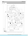
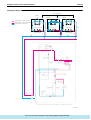
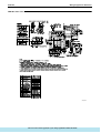
1. Refrigerant Circuit .................................................................................64
1.1 RXY5M ...................................................................................................64
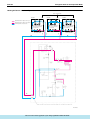
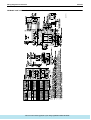
1.2 RXY8, 10, 12M .......................................................................................66
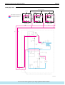
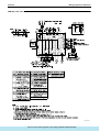
1.3 RXY14, 16M ...........................................................................................68
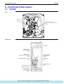
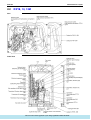
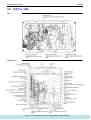
2. Functional Parts Layout ........................................................................70
2.1 RXY5M ...................................................................................................70
2.2 RXY8, 10, 12M .......................................................................................71
2.3 RXY14, 16M ...........................................................................................72
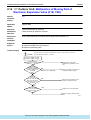
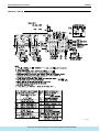
3. Refrigerant Flow for Each Operation Mode...........................................73
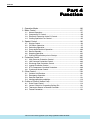
Part 4 Function............................................................................ 85
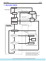
1. Operation Mode ....................................................................................86
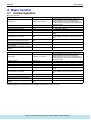
2. Basic Control.........................................................................................87
2.1
2.2
2.3
2.4
Normal Operation ...................................................................................87
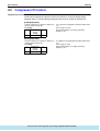
Compressor PI Control...........................................................................88
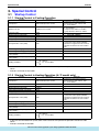
Electronic Expansion Valve PI Control...................................................94
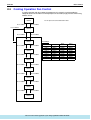
Cooling Operation Fan Control...............................................................95
3. Special Control......................................................................................96
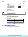
3.1 Startup Control .......................................................................................96
3.2 Oil Return Operation ..............................................................................97
Table of Contents
: http://splitoff.ru/tehn-doc.html
i
Si38-304
3.3
3.4
3.5
3.6
3.7
Defrosting Operation ..............................................................................99
Pump-down Residual Operation ..........................................................100
Restart Standby....................................................................................101
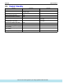
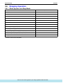
Stopping Operation ..............................................................................102
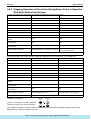
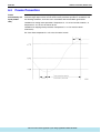
Pressure Equalization prior to Startup..................................................104
4. Protection Control ...............................................................................105
4.1
4.2
4.3
4.4
4.5
4.6
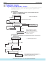
High Pressure Protection Control.........................................................105
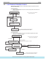
Low Pressure Protection Control..........................................................106
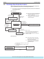
Discharge Pipe Protection Control .......................................................107
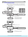
Inverter Protection Control ...................................................................108
STD Compressor Overload Protection.................................................109
Crankcase Heater Control....................................................................109
5. Other Control.......................................................................................110
5.1
5.2
5.3
5.4
Outdoor Unit Rotation...........................................................................110
Emergency Operation ..........................................................................111
Demand Operation ...............................................................................113
Heating operation prohibition ...............................................................113
6. Outline of Control (Indoor Unit) ...........................................................114
6.1
6.2
6.3
6.4
Drain Pump Control..............................................................................114
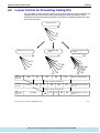
Louver Control for Preventing Ceiling Dirt............................................116
Thermostat Sensor in Remote Controller.............................................117
Freeze Prevention ................................................................................119
Part 5 Test Operation ............................................................... 121
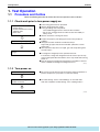
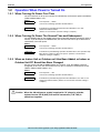
1. Test Operation ....................................................................................122
1.1 Procedure and Outline .........................................................................122
1.2 Operation When Power is Turned On ..................................................125
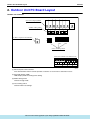
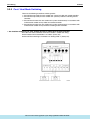
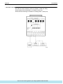
2. Outdoor Unit PC Board Layout ...........................................................126
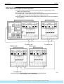
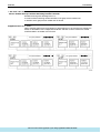
3. Field Setting ........................................................................................127
3.1 Field Setting from Remote Controller ...................................................127
3.2 Field Setting from Outdoor Unit............................................................139
Part 6 Troubleshooting ............................................................. 163
1. Troubleshooting by Remote Controller ...............................................165
1.1
1.2
1.3
1.4
The INSPECTION / TEST Button.........................................................165
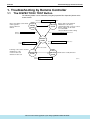
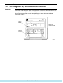
Self-diagnosis by Wired Remote Controller .........................................166
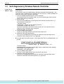
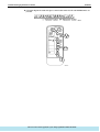
Self-diagnosis by Wireless Remote Controller .....................................167
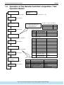
Operation of The Remote Controller’s Inspection /
Test Operation Button ..........................................................................170
1.5 Remote Controller Service Mode .........................................................171
1.6 Remote Controller Self-Diagnosis Function .........................................173
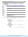
2. Troubleshooting by Indication on the Remote Controller ....................178
2.1
2.2
2.3
2.4
2.5
2.6
“A0” Indoor Unit: Error of External Protection Device ...........................178
“A1” Indoor Unit: PC Board Defect.........................................................179
“A3” Indoor Unit: Malfunction of Drain Level Control System (33H) ......180
“A6” Indoor Unit: Fan Motor (M1F) Lock, Overload...............................182
“A7” Indoor Unit: Malfunction of Swing Flap Motor (MA) .......................183
“A9” Indoor Unit: Malfunction of Moving Part of
Electronic Expansion Valve (20E) ........................................................185
2.7 “AF” Indoor Unit: Drain Level above Limit..............................................187
ii
: http://splitoff.ru/tehn-doc.html
Table of Contents
Si38-304
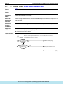
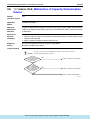
2.8 “AJ” Indoor Unit: Malfunction of Capacity Determination Device ..........188
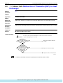
2.9 “C4” Indoor Unit: Malfunction of Thermistor (R2T)
for Heat Exchanger ..............................................................................189
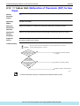
2.10 “C5” Indoor Unit: Malfunction of Thermistor (R3T) for Gas Pipes..........190
2.11 “C9” Indoor Unit: Malfunction of Thermistor (R1T) for Suction Air.........191
2.12 “CJ” Indoor Unit: Malfunction of Thermostat Sensor
in Remote Controller ............................................................................192
2.13 “E1” Outdoor Unit: PC Board Defect ......................................................193
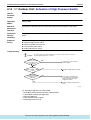
2.14 “E3” Outdoor Unit: Actuation of High Pressure Switch ..........................194
2.15 “E4” Outdoor Unit: Actuation of Low Pressure Sensor ..........................195
2.16 “E5” Compressor Motor Lock ................................................................196
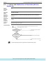
2.17 “E6” Standard Compressor Motor Overcurrent/Lock.............................197
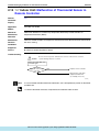
2.18 “E7” Malfunction of Outdoor Unit Fan Motor..........................................198
2.19 “E9” Outdoor Unit: Malfunction of Moving Part of
Electronic Expansion Valve (Y1E, Y2E)...............................................200
2.20 “F3” Outdoor Unit: Abnormal Discharge Pipe Temperature ..................202
2.21 “F6” Refrigerant Overcharged ...............................................................203
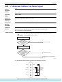
2.22 “H7” Abnormal Outdoor Fan Motor Signal .............................................204
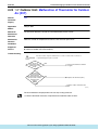
2.23 “H9” Outdoor Unit: Malfunction of Thermistor for Outdoor Air (R1T).....205
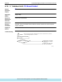
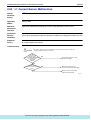
2.24 “J2” Current Sensor Malfunction...........................................................206
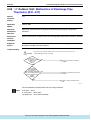
2.25 “J3” Outdoor Unit: Malfunction of Discharge Pipe Thermistor
(R31~33T) ............................................................................................207
2.26 “J5” Outdoor Unit: Malfunction of Thermistor (R2T) for Suction Pipe ...208
2.27 “J6” Outdoor Unit: Malfunction of Thermistor (R4T) for
Outdoor Unit Heat Exchanger ..............................................................209
2.28 “J9” Malfunction of Receiver Gas Pipe Thermistor (R5T).....................210
2.29 “JA” Outdoor Unit: Malfunction of High Pressure Sensor......................211
2.30 “JC” Outdoor Unit: Malfunction of Low Pressure Sensor.......................212
2.31 “L4” Outdoor Unit: Malfunction of Inverter Radiating
Fin Temperature Rise...........................................................................213
2.32 “L5” Outdoor Unit: Inverter Compressor Abnormal ...............................214
2.33 “L8” Outdoor Unit: Inverter Current Abnormal.......................................215
2.34 “L9” Outdoor Unit: Inverter Start up Error..............................................216
2.35 “LC” Outdoor Unit: Malfunction of Transmission Between Inverter
and Control PC Board ..........................................................................217
2.36 “P1” Outdoor Unit: Inverter Over-Ripple Protection ...............................219
2.37 “P4” Outdoor Unit: Malfunction of Inverter Radiating
Fin Temperature Rise Sensor ..............................................................220
2.38 “UO” Low Pressure Drop Due to Refrigerant Shortage or
Electronic Expansion Valve Failure......................................................221
2.39 “U1” Reverse Phase, Open Phase.........................................................222
2.40 “U2” Power Supply Insufficient or Instantaneous Failure ......................223
2.41 “U3” Check Operation not executed ......................................................225
2.42 “U4” Malfunction of Transmission Between Indoor Units ......................226
2.43 “U5” Malfunction of Transmission Between Remote Controller
and Indoor Unit.....................................................................................228
2.44 “U7” Malfunction of Transmission Between Outdoor Units....................229
2.45 “U8” Malfunction of Transmission Between Master
and Slave Remote Controllers .............................................................231
2.46 “U9” Malfunction of Transmission Between Indoor
and Outdoor Units in the Same System ...............................................232
2.47 “UA” Excessive Number of Indoor Units ................................................234
Table of Contents
: http://splitoff.ru/tehn-doc.html
iii
Si38-304
2.48 “UC” Address Duplication of Central Remote Controller ........................235
2.49 “UE” Malfunction of Transmission Between Central Remote Controller
and Indoor Unit.....................................................................................236
2.50 “UF” Refrigerant System not Set, Incompatible Wiring/Piping ...............238
2.51 “UH” Malfunction of System, Refrigerant System Address Undefined...239
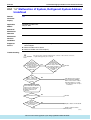
3. Troubleshooting (OP: Central Remote Controller) ..............................240
3.1 “UE” Malfunction of Transmission Between Central Remote Controller
and Indoor Unit.....................................................................................240
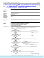
3.2 “M1” PC Board Defect ............................................................................241
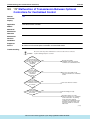
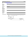
3.3 “M8” Malfunction of Transmission Between Optional Controllers
for Centralized Control .........................................................................242
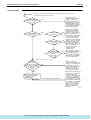
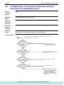
3.4 “MA” Improper Combination of Optional Controllers for
Centralized Control...............................................................................243
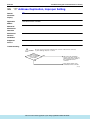
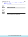
3.5 “MC” Address Duplication, Improper Setting ..........................................245
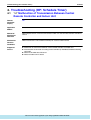
4. Troubleshooting (OP: Schedule Timer)...............................................246
4.1 “UE” Malfunction of Transmission Between Central Remote Controller
and Indoor Unit.....................................................................................246
4.2 “M1” PC Board Defect ............................................................................248
4.3 “M8” Malfunction of Transmission Between Optional Controllers for
Centralized Control...............................................................................249
4.4 “MA” Improper Combination of Optional Controllers for
Centralized Control...............................................................................250
4.5 “MC” Address Duplication, Improper Setting ..........................................252
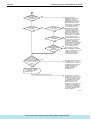
5. Troubleshooting (OP: Unified ON/OFF Controller) .............................253
5.1 Operation Lamp Blinks .........................................................................253
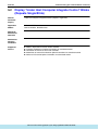
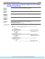
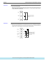
5.2 Display “Under Host Computer Integrate Control” Blinks
(Repeats Single Blink)..........................................................................255
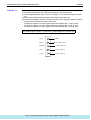
5.3 Display “Under Host Computer Integrate Control” Blinks
(Repeats Double Blink) ........................................................................258
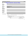
Part 7 Replacement procedure for INV compressor,
VRV II RX(Y)5M to 48M .................................................. 261
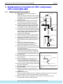
1. Replacement procedure for INV compressor,
VRV II RX(Y)5M-48M..........................................................................262
1.1 Replacement procedure .......................................................................262
Part 8 Appendix......................................................................... 263
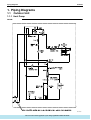
1. Piping Diagrams..................................................................................264
1.1 Outdoor Unit .........................................................................................264
1.2 Indoor Unit............................................................................................270
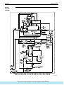
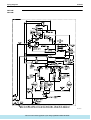
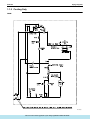
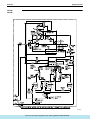
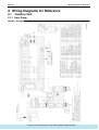
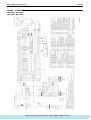
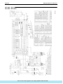
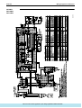
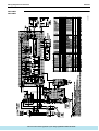
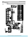
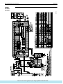
2. Wiring Diagrams for Reference...........................................................271
2.1 Outdoor Unit .........................................................................................271
2.2 Field Wiring ..........................................................................................280
2.3 Indoor Unit............................................................................................286
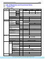
3. List of Electrical and Functional Parts .................................................298
3.1 Outdoor Unit .........................................................................................298
3.2 Indoor Side ...........................................................................................306
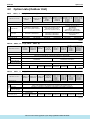
4. Option List ...........................................................................................311
4.1 Option List of Controllers......................................................................311
iv
: http://splitoff.ru/tehn-doc.html
Table of Contents
Si38-304
4.2 Option Lists (Outdoor Unit)...................................................................313
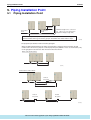
5. Piping Installation Point.......................................................................314
5.1 Piping Installation Point ........................................................................314
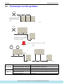
5.2 The Example of A Wrong Pattern.........................................................315
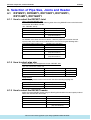
6. Selection of Pipe Size, Joints and Header ..........................................316
6.1 RXY5MY1, RXY8MY1, RXY10MY1, RXY12MY1, RXY14MY1,
RXY16MY1...........................................................................................316
6.2 RXY18MY1, RXY20MY1, RXY22MY1, RXY24MY1, RXY26MY1,
RXY28MY1, RXY30MY1, RXY32MY1, RXY34MY1, RXY36MY1,
RXY38MY1, RXY40MY1, RXY42MY1, RXY44MY1, RXY46MY1,
RXY48MY1...........................................................................................318
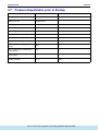
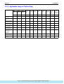
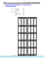
7. Thermistor Resistance / Temperature Characteristics........................321
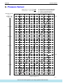
8. Pressure Sensor .................................................................................323
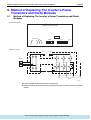
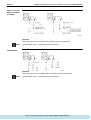
9. Method of Replacing The Inverter’s Power Transistors and
Diode Modules ....................................................................................324
Index
............................................................................................. i
Drawings & Flow Charts ................................................................ v
Table of Contents
: http://splitoff.ru/tehn-doc.html
v
Introduction
Si38-304
1. Introduction
1.1
Safety Cautions
Cautions and
Warnings
Be sure to read the following safety cautions before conducting repair work.
The caution items are classified into “
Warning” and “
Caution”. The “
Warning”
items are especially important since they can lead to death or serious injury if they are not
followed closely. The “
Caution” items can also lead to serious accidents under some
conditions if they are not followed. Therefore, be sure to observe all the safety caution items
described below.
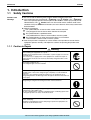
About the pictograms
This symbol indicates an item for which caution must be exercised.
The pictogram shows the item to which attention must be paid.
This symbol indicates a prohibited action.
The prohibited item or action is shown inside or near the symbol.
This symbol indicates an action that must be taken, or an instruction.
The instruction is shown inside or near the symbol.
After the repair work is complete, be sure to conduct a test operation to ensure that the
equipment operates normally, and explain the cautions for operating the product to the
customer
1.1.1 Caution in Repair
Warning
Be sure to disconnect the power cable plug from the plug socket before
disassembling the equipment for a repair.
Working on the equipment that is connected to a power supply can cause an
electrical shook.
If it is necessary to supply power to the equipment to conduct the repair or
inspecting the circuits, do not touch any electrically charged sections of the
equipment.
If the refrigerant gas discharges during the repair work, do not touch the
discharging refrigerant gas.
The refrigerant gas can cause frostbite.
When disconnecting the suction or discharge pipe of the compressor at the
welded section, release the refrigerant gas completely at a well-ventilated
place first.
If there is a gas remaining inside the compressor, the refrigerant gas or
refrigerating machine oil discharges when the pipe is disconnected, and it can
cause injury.
If the refrigerant gas leaks during the repair work, ventilate the area. The
refrigerant gas can generate toxic gases when it contacts flames.
The step-up capacitor supplies high-voltage electricity to the electrical
components of the outdoor unit.
Be sure to discharge the capacitor completely before conducting repair work.
A charged capacitor can cause an electrical shock.
Do not start or stop the air conditioner operation by plugging or unplugging the
power cable plug.
Plugging or unplugging the power cable plug to operate the equipment can
cause an electrical shock or fire.
vi
: http://splitoff.ru/tehn-doc.html
Si38-304
Introduction
Caution
Do not repair the electrical components with wet hands.
Working on the equipment with wet hands can cause an electrical shock.
Do not clean the air conditioner by splashing water.
Washing the unit with water can cause an electrical shock.
Be sure to provide the grounding when repairing the equipment in a humid or
wet place, to avoid electrical shocks.
Be sure to turn off the power switch and unplug the power cable when cleaning
the equipment.
The internal fan rotates at a high speed, and cause injury.
Do not tilt the unit when removing it.
The water inside the unit can spill and wet the furniture and floor.
Be sure to check that the refrigerating cycle section has cooled down
sufficiently before conducting repair work.
Working on the unit when the refrigerating cycle section is hot can cause burns.
Use the welder in a well-ventilated place.
Using the welder in an enclosed room can cause oxygen deficiency.
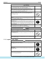
1.1.2 Cautions Regarding Products after Repair
Warning
Be sure to use parts listed in the service parts list of the applicable model and
appropriate tools to conduct repair work. Never attempt to modify the
equipment.
The use of inappropriate parts or tools can cause an electrical shock,
excessive heat generation or fire.
When relocating the equipment, make sure that the new installation site has
sufficient strength to withstand the weight of the equipment.
If the installation site does not have sufficient strength and if the installation
work is not conducted securely, the equipment can fall and cause injury.
Be sure to install the product correctly by using the provided standard
installation frame.
Incorrect use of the installation frame and improper installation can cause the
equipment to fall, resulting in injury.
Be sure to install the product securely in the installation frame mounted on a
window frame.
If the unit is not securely mounted, it can fall and cause injury.
For integral units
only
For integral units
only
Be sure to use an exclusive power circuit for the equipment, and follow the
technical standards related to the electrical equipment, the internal wiring
regulations and the instruction manual for installation when conducting
electrical work.
Insufficient power circuit capacity and improper electrical work can cause an
electrical shock or fire.
: http://splitoff.ru/tehn-doc.html
vii
Introduction
Si38-304
Warning
Be sure to use the specified cable to connect between the indoor and outdoor
units. Make the connections securely and route the cable properly so that there
is no force pulling the cable at the connection terminals.
Improper connections can cause excessive heat generation or fire.
When connecting the cable between the indoor and outdoor units, make sure
that the terminal cover does not lift off or dismount because of the cable.
If the cover is not mounted properly, the terminal connection section can cause
an electrical shock, excessive heat generation or fire.
Do not damage or modify the power cable.
Damaged or modified power cable can cause an electrical shock or fire.
Placing heavy items on the power cable, and heating or pulling the power cable
can damage the cable.
Do not mix air or gas other than the specified refrigerant in the refrigerant
system.
If air enters the refrigerating system, an excessively high pressure results,
causing equipment damage and injury.
If the refrigerant gas leaks, be sure to locate the leak and repair it before
charging the refrigerant. After charging refrigerant, make sure that there is no
refrigerant leak.
If the leak cannot be located and the repair work must be stopped, be sure to
perform pump-down and close the service valve, to prevent the refrigerant gas
from leaking into the room. The refrigerant gas itself is harmless, but it can
generate toxic gases when it contacts flames, such as fan and other heaters,
stoves and ranges.
When replacing the coin battery in the remote controller, be sure to disposed
of the old battery to prevent children from swallowing it.
If a child swallows the coin battery, see a doctor immediately.
Caution
Installation of a leakage breaker is necessary in some cases depending on the
conditions of the installation site, to prevent electrical shocks.
Do not install the equipment in a place where there is a possibility of
combustible gas leaks.
If a combustible gas leaks and remains around the unit, it can cause a fire.
Be sure to install the packing and seal on the installation frame properly.
For integral units
If the packing and seal are not installed properly, water can enter the room and only
wet the furniture and floor.
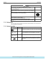
1.1.3 Inspection after Repair
Warning
Check to make sure that the power cable plug is not dirty or loose, then insert
the plug into a power outlet all the way.
If the plug has dust or loose connection, it can cause an electrical shock or fire.
If the power cable and lead wires have scratches or deteriorated, be sure to
replace them.
Damaged cable and wires can cause an electrical shock, excessive heat
generation or fire.
Do not use a joined power cable or extension cable, or share the same power
outlet with other electrical appliances, since it can cause an electrical shock,
excessive heat generation or fire.
viii
: http://splitoff.ru/tehn-doc.html
Si38-304
Introduction
Caution
Check to see if the parts and wires are mounted and connected properly, and
if the connections at the soldered or crimped terminals are secure.
Improper installation and connections can cause excessive heat generation,
fire or an electrical shock.
If the installation platform or frame has corroded, replace it.
Corroded installation platform or frame can cause the unit to fall, resulting in
injury.
Check the grounding, and repair it if the equipment is not properly grounded.
Improper grounding can cause an electrical shock.
Be sure to measure the insulation resistance after the repair, and make sure
that the resistance is 1 Mohm or higher.
Faulty insulation can cause an electrical shock.
Be sure to check the drainage of the indoor unit after the repair.
Faulty drainage can cause the water to enter the room and wet the furniture
and floor.
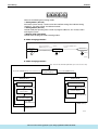
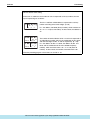
1.1.4 Using Icons
Icons are used to attract the attention of the reader to specific information. The meaning of each
icon is described in the table below:
1.1.5 Using Icons List
Icon
Type of
Information
Description
Note
A “note” provides information that is not indispensable, but may
nevertheless be valuable to the reader, such as tips and tricks.
Caution
A “caution” is used when there is danger that the reader, through
incorrect manipulation, may damage equipment, loose data, get
an unexpected result or has to restart (part of) a procedure.
Warning
A “warning” is used when there is danger of personal injury.
Reference
A “reference” guides the reader to other places in this binder or
in this manual, where he/she will find additional information on a
specific topic.
Note:
Caution
Warning
: http://splitoff.ru/tehn-doc.html
ix
Introduction
1.2
Si38-304
PREFACE
Thank you for your continued patronage of Daikin products.
This is the new service manual for Daikin's Year 2003 VRVII series Heat Pump / Cooling Only
System.
Daikin offers a wide range of models to respond to building and office air conditioning needs.
We are confident that customers will be able to find the models that best suit their needs.
This service manual contains information regarding the servicing of VRVII series Heat Pump /
Cooling Only System.
July. 2003
After Sales Service Division
x
: http://splitoff.ru/tehn-doc.html
Si38-304
Part 1
General Information
1. Model Names of Indoor/Outdoor Units....................................................2
2. External Appearance...............................................................................3
2.1 Indoor Units ..............................................................................................3
2.2 Outdoor Units ...........................................................................................4
3. Combination of Outdoor Units.................................................................5
4. Capacity Range.......................................................................................6
General Information
: http://splitoff.ru/tehn-doc.html
1
Model Names of Indoor/Outdoor Units
Si38-304
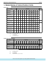
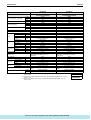
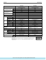
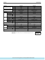
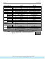
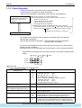
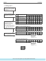
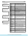
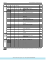
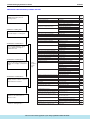
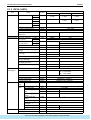
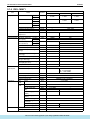
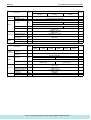
1. Model Names of Indoor/Outdoor Units
Indoor Units
Type
Power
Supply
Model Name
Ceiling Mounted
Cassette Type
(Double Flow)
FXC
20L
25L
32L
40L
50L
63L
80L
—
125L
—
—
Ceiling Mounted
Cassette Type
(Multi Flow)
FXF
—
25L
32L
40L
50L
63L
80L
100L
125L
—
—
Ceiling Mounted
Cassette Corner Type
FXK
—
25L
32L
40L
—
63L
—
—
—
—
—
Ceiling Mounted Low
Silhouette Duct Type
FXYD
—
—
—
—
—
Ceiling Mounted
Built-In Type
FXS
20KA 25KA 32KA 40KA 50KA 63KA
20L
25L
32L
40L
50L
63L
80L
100L
125L
—
—
20K
25K
32K
40K
50K
63K
80K
100K
125K
—
—
FXM
—
—
—
40L
50L
63L
80L
100L
125L
200L
250L
Ceiling Suspended Type FXH
—
—
32L
—
—
63L
—
100L
—
—
—
Ceiling Mounted Built-In FXYB
(Rear Suction) Type
Ceiling Mounted
Duct Type
Wall Mounted Type
FXA
20L
25L
32L
40L
50L
63L
—
—
—
—
—
Floor Standing Type
FXL
20L
25L
32L
40L
50L
63L
—
—
—
—
—
Concealed
Floor Standing Type
FXN
20L
25L
32L
40L
50L
63L
—
—
—
—
—
VE:
VE
V1
VE
1φ, 220V~240V, 50Hz
1φ, 220V, 60Hz
V1:
1φ, 220V~240V, 50Hz
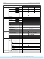
Outdoor Units (Inverter Series)
Series
Heat Pump
Cooling Only
RXY
5M
8M
10M
12M
14M
16M
18M
20M
22M
24M
26M
Y1 (E)
TL (E)
YL (E)
RX
5M
8M
10M
12M
14M
16M
18M
20M
22M
24M
26M
Y1 (E)
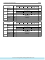
Series
Heat Pump
Cooling Only
2
Power
Supply
Model Name
Power
Supply
Model Name
RXY
28M
30M
32M
34M
36M
38M
40M
42M
44M
46M
48M
Y1 (E)
TL (E)
YL (E)
RX
28M
30M
32M
34M
36M
38M
40M
42M
44M
46M
48M
Y1 (E)
Y1:
3φ, 380~415V, 50Hz
TL:
3φ, 220V, 60Hz
YL:
3φ, 380V, 60Hz
E:
The unit with anti corrosion treatment
: http://splitoff.ru/tehn-doc.html General Information
Si38-304
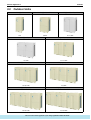
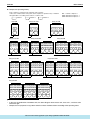
External Appearance
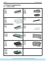
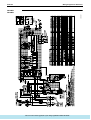
2. External Appearance
2.1
Indoor Units
Ceiling mounted cassette type (Double flow)
FXC20L
FXC25L
FXC32L
FXC40L
FXC50L
FXC63L
FXC80L
FXC125L
Ceiling mounted duct type
FXM40L
FXM50L
FXM63L
FXM80L
FXM100L
FXM125L
FXM200L
FXM250L
FXM40~125L
FXM200 · 250L
Ceiling mounted cassette type (Multi flow)
FXF25L
FXF32L
FXF40L
FXF50L
FXF63L
FXF80L
FXF100L
FXF125L
Ceiling mounted cassette corner type
FXK25L
FXK32L
FXK40L
FXK63L
Ceiling mounted low silhouette duct type
FXYD20KA
FXYD25KA
FXYD32KA
FXYD40KA
FXYD50KA
FXYD63KA
Ceiling mounted built-in type
FXS20L
FXS25L
FXS32L
FXS40L
FXS50L
FXS63L
FXS80L
FXS100L
FXS125L
Ceiling suspended type
FXH32L
FXH63L
FXH100L
Wall mounted type
FXA20L
FXA25L
FXA32L
FXA40L
FXA50L
FXA63L
Floor standing type
FXL20L
FXL25L
FXL32L
FXL40L
FXL50L
FXL63L
Concealed floor standing type
FXN20L
FXN25L
FXN32L
FXN40L
FXN50L
FXN63L
Ceiling mounted built-in type -rear suction type FXYB20K
FXYB25K
FXYB32K
FXYB40K
FXYB50K
FXYB63K
FXYB80K
FXYB100K
FXYB125K
General Information
: http://splitoff.ru/tehn-doc.html
3
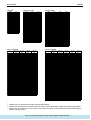
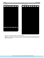
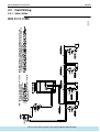
External Appearance
2.2
Si38-304
Outdoor Units
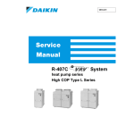
RX (Y) 5M
RX (Y) 8M,10M
RX (Y) 12M,14M,16M
5HP
8,10HP
12,14,16HP
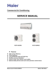
RX (Y) 18M, 20M
4
RX (Y) 22M, 24M, 26M
18, 20HP
22, 24, 26HP
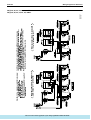
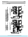
RX (Y) 28M, 30M, 32M
RX (Y) 34M, 36M
28, 30, 32HP
34, 36HP
RX (Y) 38M, 40M, 42M
RX (Y) 44M, 46M, 48M
38, 40, 42HP
44, 46, 48HP
: http://splitoff.ru/tehn-doc.html General Information
Si38-304
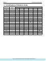
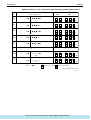
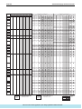
Combination of Outdoor Units
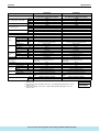
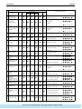
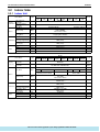
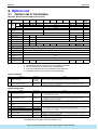
3. Combination of Outdoor Units
Module
System
Number of
Capacity
units
5
8
10
12
5HP
1
O
8HP
1
O
10HP
1
O
12HP
1
O
14HP
1
16HP
1
18HP
2
O
O
20HP
2
OO
22HP
2
O
O
24HP
2
O
26HP
2
O
28HP
2
O
30HP
2
32HP
2
34HP
3
OO
36HP
3
OO
38HP
3
O
O
40HP
3
O
42HP
3
O
44HP
3
O
46HP
3
48HP
3
∗ Up to a maximum 48HP are realized by combining 8, 10, 12, 14 and 16HP.
General Information
14
16
O
O
O
O
O
O
O
OO
O
O
O
: http://splitoff.ru/tehn-doc.html
O
O
O
OO
OO
OO
OOO
5
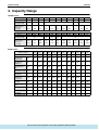
Capacity Range
Si38-304
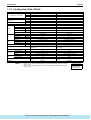
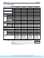
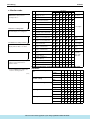
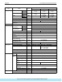
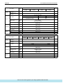
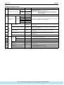
4. Capacity Range
Outdoor Units
Capacity Range
5HP
8HP
10HP
12HP
14HP
16HP
18HP
20HP
22HP
24HP
26HP
RX (Y)
5M
8M
10M
12M
14M
16M
18M
20M
22M
24M
26M
No of Indoor Units
to be Connected
8
13
16
62.5
~
162.5
100
~
260
125
~
325
150
~
390
175
~
455
200
~
520
225
~
585
250
~
650
275
~
715
300
~
780
325
~
845
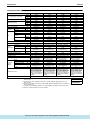
Capacity Range
28HP
30HP
32HP
34HP
36HP
38HP
40HP
42HP
44HP
46HP
48HP
RX (Y)
28M
30M
32M
34M
36M
38M
40M
42M
44M
46M
48M
34
36
38
425
~
1105
450
~
1170
475
~
1235
575
~
1495
600
~
1560
Total Capacity
Index of Indoor
Units to be
Connected
No of Indoor Units
to be Connected
20
32
Total Capacity
Index of Indoor
Units to be
Connected
350
~
910
22
32
40
375
~
975
400
~
1040
500
~
1300
525
~
1365
550
~
1430
Capacity Range
0.8
HP
1
HP
1.25
HP
1.6
HP
2
HP
2.5
HP
3
HP
3.2
HP
4
HP
5
HP
8
HP
10
HP
Capacity Index
20
25
31.25
40
50
62.5
71
80
100
125
200
250
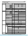
Indoor Units
Ceiling Mounted
Cassette Type
(Double Flow)
FXC
20L
25L
32L
40L
50L
63L
—
80L
—
125L
—
—
Ceiling Mounted
Cassette Type
(Multi Flow)
FXF
—
25L
32L
40L
50L
63L
—
80L
100L
125L
—
—
Ceiling Mounted
Cassette Corner
Type
FXK
—
25L
32L
40L
—
63L
—
—
—
—
—
—
20KA
25KA
32KA
40KA
50KA
63KA
—
—
—
—
—
—
Ceiling Mounted Low
Silhouette Duct Type FXYD
6
Ceiling Mounted
Built-In Type
FXS
20L
25L
32L
40L
50L
63L
80L
100L
125L
—
—
—
Ceiling Mounted
Built-In (Rear
Suction) Type
FXYB
20K
25K
32K
40K
50K
63K
—
80K
100K
125K
—
—
Ceiling Mounted
Duct Type
Ceiling Suspended
Type
FXM
—
—
—
40L
50L
63L
—
80L
100L
125L
200L
250L
FXH
—
—
32L
—
—
63L
—
—
100L
—
—
—
Wall Mounted Type
FXA
20L
25L
32L
40L
50L
63L
—
—
—
—
—
—
Floor Standing Type FXL
20L
25L
32L
40L
50L
63L
—
—
—
—
—
—
Concealed
FXN
Floor Standing Type
20L
25L
32L
40L
50L
63L
—
—
—
—
—
—
: http://splitoff.ru/tehn-doc.html General Information
Si38-304
Part 2
Specifications
1. Specifications ..........................................................................................8
1.1 Outdoor Units ...........................................................................................8
1.2 Indoor Units ............................................................................................41
Specifications
: http://splitoff.ru/tehn-doc.html
7
Specifications
Si38-304
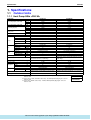
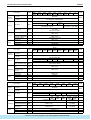
1. Specifications
1.1
Outdoor Units
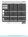
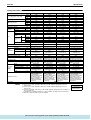
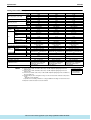
1.1.1 Heat Pump 50Hz <RXY-M>
Model Name
RXY5MY1(E)
RXY8MY1(E)
+1 Cooling Capacity (19.5°CWB)
kcal / h
Btu / h
12,500
49,200
22,400
88,800
+2 Cooling Capacity (19.0°CWB)
kW
kW
14.4
14.0
26.0
25.2
kcal / h
Btu / h
13,800
54,600
21,500
85,400
kW
Y1
16.0
Ivory White (5Y7.5/1)
25.0
Ivory White (5Y7.5/1)
Y1E
mm
Light Camel (2.5Y6.5/1.5)
1600×635×765
Light Camel (2.5Y6.5/1.5)
1600×930×765
Cross Fin Coil
Hermetically Sealed Scroll Type
Cross Fin Coil
Hermetically Sealed Scroll Type
19.36
6480
19.36+14.68
6480, 2900
+3 Heating Capacity
Casing Color
Dimensions: (H×W×D)
Heat Exchanger
Type
Comp.
Fan
Connecting
Pipes
Piston Displacement
Number of Revolutions
m³/h
r.p.m
Motor Output×Number
of Units
Starting Method
kW
Type
Motor Output
3.5×1
(1.2+4.5)×1
Direct on Line
Direct on Line
Propeller Fan
0.35×1
Propeller Fan
0.75×1
m³/min
75
Direct Drive
175
Direct Drive
mm
mm
φ9.5 (Flare Connection)
φ19.1 (Brazing Connection)
φ12.7 (Brazing Connection)
φ28.6 (Brazing Connection)
mm
kg
—
160
—
235
kW
Air Flow Rate
Drive
Liquid Pipe
Gas Pipe
Oil Equalizing Pipe
Machine Weight
High Pressure Switch, Fan Driver Overload Protector,
Inverter Overload Protector, Fusible Plugs
Safety Devices
Defrost Method
Capacity Control
Refrigerant
Refrigerant Name
Charge
%
Deicer
24~100
Deicer
14~100
kg
R22
8.5
R22
13.1
Electronic Expansion Valve
SUNISO 4GSDID-K
Electronic Expansion Valve
SUNISO 4GSDID-K
Control
Refrigerator
Oil
Charge Volume
Standard Accessories
High Pressure Switch, Fan Driver Overload Protector, Over
Current Relay, Inverter Overload Protector,
Fusible Plugs
L
1.2
Installation Manual, Operation Manual, Connection Pipes,
Clamps
Drawing No.
1.9+1.6
Installation Manual, Operation Manual, Connection Pipes,
Clamps
4D038970
Notes:
4D038971A
+1 Indoor temp. : 27°CDB, 19.5°CWB / outdoor temp. : 35°CDB / Equivalent piping length : 7.5m, level
difference : 0m.
+2 Indoor temp. : 27°CDB, 19.0°CWB / outdoor temp. : 35°CDB / Equivalent piping length : 7.5m, level
difference : 0m.
+3 Indoor temp. : 20°CDB / outdoor temp. : 7°CDB, 6°CWB / Equivalent piping length : 7.5m, level
difference : 0m.
8
: http://splitoff.ru/tehn-doc.html
Conversion Formulae
kcal/h=kW×860
Btu/h=kW×3414
cfm=m³/min×35.3
Specifications
Si38-304
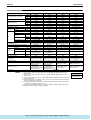
Specifications
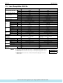
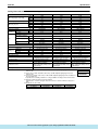
Model Name
RXY10MY1(E)
RXY12MY1(E)
+1 Cooling Capacity (19.5°CWB)
kcal / h
Btu / h
25,000
98,700
30,000
118,000
+2 Cooling Capacity (19.0°CWB)
kW
kW
28.9
28.0
34.5
33.5
kcal / h
Btu / h
27,000
108,000
30,000
118,000
kW
Y1
31.5
Ivory White (5Y7.5/1)
34.7
Ivory White (5Y7.5/1)
Y1E
mm
Light Camel (2.5Y6.5/1.5)
1600×930×765
Light Camel (2.5Y6.5/1.5)
1600×1240×765
Cross Fin Coil
Hermetically Sealed Scroll Type
Cross Fin Coil
Hermetically Sealed Scroll Type
19.36+14.68
6480, 2900
19.36+14.68
6480, 2900
+3 Heating Capacity
Casing Color
Dimensions: (H×W×D)
Heat Exchanger
Type
Comp.
Fan
Connecting
Pipes
Piston Displacement
Number of Revolutions
m³/h
r.p.m
Motor Output×Number
of Units
Starting Method
kW
Type
Motor Output
(2.75+4.5)×1
(4.2+4.5)×1
Direct on Line
Direct on Line
Propeller Fan
0.75×1
Propeller Fan
0.75×1
m³/min
180
Direct Drive
210
Direct Drive
mm
mm
φ12.7 (Brazing Connection)
φ28.6 (Brazing Connection)
φ15.9 (Brazing Connection)
φ34.9 (Brazing Connection)
mm
kg
—
235
—
290
High Pressure Switch, Fan Driver Overload Protector, Over
Current Relay, Inverter Overload Protector,
Fusible Plugs
High Pressure Switch, Fan Driver Overload Protector, Over
Current Relay, Inverter Overload Protector,
Fusible Plugs
%
Deicer
14~100
Deicer
14~100
kg
R22
13.9
R22
15.6
Electronic Expansion Valve
SUNISO 4GSDID-K
Electronic Expansion Valve
SUNISO 4GSDID-K
kW
Air Flow Rate
Drive
Liquid Pipe
Gas Pipe
Oil Equalizing Pipe
Machine Weight
Safety Devices
Defrost Method
Capacity Control
Refrigerant
Refrigerant Name
Charge
Control
Refrigerator
Oil
Charge Volume
Standard Accessories
L
1.9+1.6
Installation Manual, Operation Manual, Connection Pipes,
Clamps
Drawing No.
1.9+1.6
Installation Manual, Operation Manual, Connection Pipes,
Clamps
4D038972A
Notes:
4D038973A
+1 Indoor temp. : 27°CDB, 19.5°CWB / outdoor temp. : 35°CDB / Equivalent piping length : 7.5m, level
difference : 0m.
+2 Indoor temp. : 27°CDB, 19.0°CWB / outdoor temp. : 35°CDB / Equivalent piping length : 7.5m, level
difference : 0m.
+3 Indoor temp. : 20°CDB / outdoor temp. : 7°CDB, 6°CWB / Equivalent piping length : 7.5m, level
difference : 0m.
Specifications
: http://splitoff.ru/tehn-doc.html
Conversion Formulae
kcal/h=kW×860
Btu/h=kW×3414
cfm=m³/min×35.3
9
Specifications
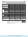
Si38-304
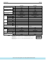
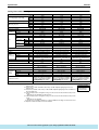
Model Name
RXY14MY1(E)
RXY16MY1(E)
+1 Cooling Capacity (19.5°CWB)
kcal / h
Btu / h
35,500
141,000
40,000
158,000
+2 Cooling Capacity (19.0°CWB)
kW
kW
41.2
40.0
46.4
45.0
kcal / h
Btu / h
35,500
142,000
40,000
154,000
kW
Y1
41.5
Ivory White (5Y7.5/1)
45.0
Ivory White (5Y7.5/1)
Y1E
mm
Light Camel (2.5Y6.5/1.5)
1600×1240×765
Light Camel (2.5Y6.5/1.5)
1600×1240×765
Cross Fin Coil
Hermetically Sealed Scroll Type
Cross Fin Coil
Hermetically Sealed Scroll Type
+3 Heating Capacity
Casing Color
Dimensions: (H×W×D)
Heat Exchanger
Type
Comp.
Fan
Connecting
Pipes
Piston Displacement
Number of Revolutions
m³/h
r.p.m
19.36+14.68+14.68
6480, 2900×2
19.36+14.68+14.68
6480, 2900×2
Motor Output×Number
of Units
Starting Method
kW
(2.0+4.5+4.5)×1
(3.0+4.5+4.5)×1
Direct on Line
Direct on Line
Propeller Fan
0.75×1
Propeller Fan
0.75×1
m³/min
210
Direct Drive
210
Direct Drive
mm
mm
φ15.9 (Brazing Connection)
φ34.9 (Brazing Connection)
φ15.9 (Brazing Connection)
φ34.9 (Brazing Connection)
mm
kg
—
331
—
333
High Pressure Switch, Fan Driver Overload Protector, Over
Current Relay, Inverter Overload Protector,
Fusible Plugs
High Pressure Switch, Fan Driver Overload Protector, Over
Current Relay, Inverter Overload Protector,
Fusible Plugs
%
Deicer
10~100
Deicer
10~100
kg
R22
17.1
R22
18.6
Electronic Expansion Valve
SUNISO 4GSDID-K
Electronic Expansion Valve
SUNISO 4GSDID-K
Type
Motor Output
kW
Air Flow Rate
Drive
Liquid Pipe
Gas Pipe
Oil Equalizing Pipe
Machine Weight
Safety Devices
Defrost Method
Capacity Control
Refrigerant
Refrigerant Name
Charge
Control
Refrigerator
Oil
Charge Volume
Standard Accessories
L
1.9+1.6+1.6
Installation Manual, Operation Manual, Connection Pipes,
Clamps
Drawing No.
1.9+1.6+1.6
Installation Manual, Operation Manual, Connection Pipes,
Clamps
4D038974A
Notes:
4D038975A
+1 Indoor temp. : 27°CDB, 19.5°CWB / outdoor temp. : 35°CDB / Equivalent piping length : 7.5m, level
difference : 0m.
+2 Indoor temp. : 27°CDB, 19.0°CWB / outdoor temp. : 35°CDB / Equivalent piping length : 7.5m, level
difference : 0m.
+3 Indoor temp. : 20°CDB / outdoor temp. : 7°CDB, 6°CWB / Equivalent piping length : 7.5m, level
difference : 0m.
10
: http://splitoff.ru/tehn-doc.html
Conversion Formulae
kcal/h=kW×860
Btu/h=kW×3414
cfm=m³/min×35.3
Specifications
Si38-304
Specifications
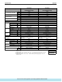
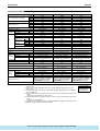
Model Name (Combination Unit)
RXY18MY1(E)
RXY20MY1(E)
Model Name (Independent Unit)
RXY10MY1(E)+RXY10MY1(E)
50,000
kcal / h
RXY8MY1(E)+RXY10MY1(E)
47,400
+1 Cooling Capacity (19.5°CWB)
Btu / h
kW
188,000
54.8
197,000
57.7
+2 Cooling Capacity (19.0°CWB)
kW
kcal / h
53.2
48,500
56.0
54,000
+3 Heating Capacity
Btu / h
kW
193,000
56.5
216,000
63.0
Y1
Y1E
Ivory White (5Y7.5/1)
Light Camel (2.5Y6.5/1.5)
Ivory White (5Y7.5/1)
Light Camel (2.5Y6.5/1.5)
mm
(1600×930×765)+(1600×930×765)
Cross Fin Coil
(1600×930×765)+(1600×930×765)
Cross Fin Coil
m³/h
Hermetically Sealed Scroll Type
(19.36+14.68)×2
Hermetically Sealed Scroll Type
(19.36+14.68)×2
r.p.m
(6480, 2900)×2
(6480, 2900)×2
kW
(1.2+4.5)+(2.75+4.5)
(2.75+4.5)×2
Direct on Line
Propeller Fan
Direct on Line
Propeller Fan
kW
m³/min
0.75×2
175+180
0.75×2
180+180
Drive
Liquid Pipe
mm
Direct Drive
φ19.1 (Brazing Connection)
Direct Drive
φ19.1 (Brazing Connection)
Gas Pipe
Oil Equalizing Pipe
mm
mm
φ34.9 (Brazing Connection)
φ6.4 (Flare Connection)
φ34.9 (Brazing Connection)
φ6.4 (Flare Connection)
kg
235+235
High Pressure Switch, Fan Driver Overload Protector, Over
Current Relay, Inverter Overload Protector,
Fusible Plugs
Deicer
235+235
High Pressure Switch, Fan Driver Overload Protector, Over
Current Relay, Inverter Overload Protector,
Fusible Plugs
Deicer
Capacity Control
Refrigerant Name
%
7~100
R22
7~100
R22
Refrigerant
Charge
Control
kg
13.1+13.9
Electronic Expansion Valve
13.9+13.9
Electronic Expansion Valve
Charge Volume
L
SUNISO 4GSDID-K
(1.9+1.6)+(1.9+1.6)
SUNISO 4GSDID-K
(1.9+1.6)+(1.9+1.6)
Casing Color
Dimensions: (H×W×D)
Heat Exchanger
Type
Piston Displacement
Comp.
Number of Revolutions
Motor Output×Number
of Units
Starting Method
Type
Fan
Connecting
Pipes
Motor Output
Air Flow Rate
Machine Weight
Safety Devices
Defrost Method
Refrigerator
Oil
Standard Accessories
Drawing No.
Notes:
Installation Manual, Operation Manual, Connection Pipes,
Clamps
4D038971A, 4D038972A
Installation Manual, Operation Manual, Connection Pipes,
Clamps
4D038972A
+1 Indoor temp. : 27°CDB, 19.5°CWB / outdoor temp. : 35°CDB / Equivalent piping length : 7.5m, level
difference : 0m.
+2 Indoor temp. : 27°CDB, 19.0°CWB / outdoor temp. : 35°CDB / Equivalent piping length : 7.5m, level
difference : 0m.
+3 Indoor temp. : 20°CDB / outdoor temp. : 7°CDB, 6°CWB / Equivalent piping length : 7.5m, level
difference : 0m.
Specifications
: http://splitoff.ru/tehn-doc.html
Conversion Formulae
kcal/h=kW×860
Btu/h=kW×3414
cfm=m³/min×35.3
11
Specifications
Si38-304
Model Name (Combination Unit)
RXY22MY1(E)
RXY24MY1(E)
Model Name (Independent Unit)
RXY10MY1(E)+RXY14MY1(E)
60,500
kcal / h
RXY10MY1(E)+RXY12MY1(E)
55,000
+1 Cooling Capacity (19.5°CWB)
Btu / h
kW
217,000
63.4
240,000
70.1
+2 Cooling Capacity (19.0°CWB)
kW
kcal / h
61.5
57,000
68.0
62,500
+3 Heating Capacity
Btu / h
kW
226,000
66.2
250,000
73.0
Y1
Y1E
Ivory White (5Y7.5/1)
Light Camel (2.5Y6.5/1.5)
Ivory White (5Y7.5/1)
Light Camel (2.5Y6.5/1.5)
mm
(1600×930×765)+(1600×1240×765)
Cross Fin Coil
(1600×930×765)+(1600×1240×765)
Cross Fin Coil
m³/h
Hermetically Sealed Scroll Type
(19.36+14.68)×2
Hermetically Sealed Scroll Type
(19.36+14.68)+(19.36+14.68+14.68)
r.p.m
(6480, 2900)×2
(6480, 2900)+(6480, 2900×2)
kW
(2.75+4.5)+(4.2+4.5)
(2.75+4.5)+(2.0+4.5+4.5)
Direct on Line
Propeller Fan
Direct on Line
Propeller Fan
kW
m³/min
0.75×2
180+210
0.75×2
180+210
Drive
Liquid Pipe
mm
Direct Drive
φ19.1 (Brazing Connection)
Direct Drive
φ19.1 (Brazing Connection)
Gas Pipe
Oil Equalizing Pipe
mm
mm
φ34.9 (Brazing Connection)
φ6.4 (Flare Connection)
φ41.3 (Brazing Connection)
φ6.4 (Flare Connection)
kg
235+290
High Pressure Switch, Fan Driver Overload Protector, Over
Current Relay, Inverter Overload Protector,
Fusible Plugs
Deicer
235+331
High Pressure Switch, Fan Driver Overload Protector, Over
Current Relay, Inverter Overload Protector,
Fusible Plugs
Deicer
Capacity Control
Refrigerant Name
%
7~100
R22
6~100
R22
Refrigerant
Charge
Control
kg
13.9+15.6
Electronic Expansion Valve
13.9+17.1
Electronic Expansion Valve
Charge Volume
L
SUNISO 4GSDID-K
(1.9+1.6)+(1.9+1.6)
SUNISO 4GSDID-K
(1.9+1.6)+(1.9+1.6+1.6)
Casing Color
Dimensions: (H×W×D)
Heat Exchanger
Type
Piston Displacement
Comp.
Number of Revolutions
Motor Output×Number
of Units
Starting Method
Type
Fan
Connecting
Pipes
Motor Output
Air Flow Rate
Machine Weight
Safety Devices
Defrost Method
Refrigerator
Oil
Standard Accessories
Drawing No.
Notes:
Installation Manual, Operation Manual, Connection Pipes,
Clamps
4D038972A, 4D038973A
Installation Manual, Operation Manual, Connection Pipes,
Clamps
4D038972A, 4D038974A
+1 Indoor temp. : 27°CDB, 19.5°CWB / outdoor temp. : 35°CDB / Equivalent piping length : 7.5m, level
difference : 0m.
+2 Indoor temp. : 27°CDB, 19.0°CWB / outdoor temp. : 35°CDB / Equivalent piping length : 7.5m, level
difference : 0m.
+3 Indoor temp. : 20°CDB / outdoor temp. : 7°CDB, 6°CWB / Equivalent piping length : 7.5m, level
difference : 0m.
12
: http://splitoff.ru/tehn-doc.html
Conversion Formulae
kcal/h=kW×860
Btu/h=kW×3414
cfm=m³/min×35.3
Specifications
Si38-304
Specifications
Model Name (Combination Unit)
RXY26MY1(E)
RXY28MY1(E)
Model Name (Independent Unit)
RXY12MY1(E)+RXY16MY1(E)
70,000
kcal / h
RXY10MY1(E)+RXY16MY1(E)
65,000
+1 Cooling Capacity (19.5°CWB)
Btu / h
kW
257,000
75.3
276,000
80.9
+2 Cooling Capacity (19.0°CWB)
kW
kcal / h
73.0
67,000
78.5
70,000
+3 Heating Capacity
Btu / h
kW
262,000
76.5
272,000
79.7
Y1
Y1E
Ivory White (5Y7.5/1)
Light Camel (2.5Y6.5/1.5)
Ivory White (5Y7.5/1)
Light Camel (2.5Y6.5/1.5)
mm
(1600×930×765)+(1600×1240×765)
Cross Fin Coil
(1600×1240×765)+(1600×1240×765)
Cross Fin Coil
m³/h
Hermetically Sealed Scroll Type
(19.36+14.68)+(19.36+14.68+14.68)
Hermetically Sealed Scroll Type
(19.36+14.68)+(19.36+14.68+14.68)
r.p.m
(6480, 2900)+(6480, 2900×2)
(6480, 2900)+(6480, 2900×2)
kW
(2.75+4.5)+(3.0+4.5+4.5)
(4.2+4.5)+(3.0+4.5+4.5)
Direct on Line
Propeller Fan
Direct on Line
Propeller Fan
kW
m³/min
0.75×2
180+210
0.75×2
210+210
Drive
Liquid Pipe
mm
Direct Drive
φ22.2 (Brazing Connection)
Direct Drive
φ22.2 (Brazing Connection)
Gas Pipe
Oil Equalizing Pipe
mm
mm
φ41.3 (Brazing Connection)
φ6.4 (Flare Connection)
φ41.3 (Brazing Connection)
φ6.4 (Flare Connection)
kg
235+333
High Pressure Switch, Fan Driver Overload Protector, Over
Current Relay, Inverter Overload Protector,
Fusible Plugs
Deicer
290+333
High Pressure Switch, Fan Driver Overload Protector, Over
Current Relay, Inverter Overload Protector,
Fusible Plugs
Deicer
Capacity Control
Refrigerant Name
%
6~100
R22
6~100
R22
Refrigerant
Charge
Control
kg
13.9+18.6
Electronic Expansion Valve
15.6+18.6
Electronic Expansion Valve
Charge Volume
L
SUNISO 4GSDID-K
(1.9+1.6)+(1.9+1.6+1.6)
SUNISO 4GSDID-K
(1.9+1.6)+(1.9+1.6+1.6)
Casing Color
Dimensions: (H×W×D)
Heat Exchanger
Type
Piston Displacement
Comp.
Number of Revolutions
Motor Output×Number
of Units
Starting Method
Type
Fan
Connecting
Pipes
Motor Output
Air Flow Rate
Machine Weight
Safety Devices
Defrost Method
Refrigerator
Oil
Standard Accessories
Drawing No.
Notes:
Installation Manual, Operation Manual, Connection Pipes,
Clamps
4D038972A, 4D038975A
Installation Manual, Operation Manual, Connection Pipes,
Clamps
4D038973A, 4D038975A
+1 Indoor temp. : 27°CDB, 19.5°CWB / outdoor temp. : 35°CDB / Equivalent piping length : 7.5m, level
difference : 0m.
+2 Indoor temp. : 27°CDB, 19.0°CWB / outdoor temp. : 35°CDB / Equivalent piping length : 7.5m, level
difference : 0m.
+3 Indoor temp. : 20°CDB / outdoor temp. : 7°CDB, 6°CWB / Equivalent piping length : 7.5m, level
difference : 0m.
Specifications
: http://splitoff.ru/tehn-doc.html
Conversion Formulae
kcal/h=kW×860
Btu/h=kW×3414
cfm=m³/min×35.3
13
Specifications
Si38-304
Model Name (Combination Unit)
RXY30MY1(E)
RXY32MY1(E)
Model Name (Independent Unit)
RXY16MY1(E)+RXY16MY1(E)
80,000
kcal / h
RXY14MY1(E)+RXY16MY1(E)
75,500
+1 Cooling Capacity (19.5°CWB)
Btu / h
kW
299,000
87.6
316,000
92.8
+2 Cooling Capacity (19.0°CWB)
kW
kcal / h
85.0
75,500
90.0
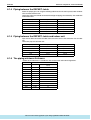
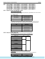
80,000
+3 Heating Capacity
Btu / h
kW
296,000
86.5
308,000
90.0
Y1
Y1E
Ivory White (5Y7.5/1)
Light Camel (2.5Y6.5/1.5)
Ivory White (5Y7.5/1)
Light Camel (2.5Y6.5/1.5)
mm
(1600×1240×765)+(1600×1240×765)
Cross Fin Coil
(1600×1240×765)+(1600×1240×765)
Cross Fin Coil
m³/h
Hermetically Sealed Scroll Type
(19.36+14.68+14.68)×2
Hermetically Sealed Scroll Type
(19.36+14.68+14.68)×2
r.p.m
(6480, 2900×2)×2
(6480, 2900×2)×2
kW
(2.0+4.5+4.5)+(3.0+4.5+4.5)
(3.0+4.5+4.5)+(3.0+4.5+4.5)
Direct on Line
Propeller Fan
Direct on Line
Propeller Fan
kW
m³/min
0.75×2
210×2
0.75×2
210×2
Drive
Liquid Pipe
mm
Direct Drive
φ22.2 (Brazing Connection)
Direct Drive
φ22.2 (Brazing Connection)
Gas Pipe
Oil Equalizing Pipe
mm
mm
φ41.3 (Brazing Connection)
φ6.4 (Flare Connection)
φ41.3 (Brazing Connection)
φ6.4 (Flare Connection)
kg
331+333
High Pressure Switch, Fan Driver Overload Protector, Over
Current Relay, Inverter Overload Protector,
Fusible Plugs
Deicer
333+333
High Pressure Switch, Fan Driver Overload Protector, Over
Current Relay, Inverter Overload Protector,
Fusible Plugs
Deicer
Capacity Control
Refrigerant Name
%
5~100
R22
5~100
R22
Refrigerant
Charge
Control
kg
17.1+18.6
Electronic Expansion Valve
18.6+18.6
Electronic Expansion Valve
Charge Volume
L
SUNISO 4GSDID-K
(1.9+1.6+1.6)+(1.9+1.6+1.6)
SUNISO 4GSDID-K
(1.9+1.6+1.6)+(1.9+1.6+1.6)
Installation Manual, Operation Manual, Connection Pipes,
Clamps
4D038974A, 4D038975A
Installation Manual, Operation Manual, Connection Pipes,
Clamps
4D038975A
Casing Color
Dimensions: (H×W×D)
Heat Exchanger
Type
Piston Displacement
Comp.
Number of Revolutions
Motor Output×Number
of Units
Starting Method
Type
Fan
Connecting
Pipes
Motor Output
Air Flow Rate
Machine Weight
Safety Devices
Defrost Method
Refrigerator
Oil
Standard Accessories
Drawing No.
Notes:
+1 Indoor temp. : 27°CDB, 19.5°CWB / outdoor temp. : 35°CDB / Equivalent piping length : 7.5m, level
difference : 0m.
+2 Indoor temp. : 27°CDB, 19.0°CWB / outdoor temp. : 35°CDB / Equivalent piping length : 7.5m, level
difference : 0m.
+3 Indoor temp. : 20°CDB / outdoor temp. : 7°CDB, 6°CWB / Equivalent piping length : 7.5m, level
difference : 0m.
14
: http://splitoff.ru/tehn-doc.html
Conversion Formulae
kcal/h=kW×860
Btu/h=kW×3414
cfm=m³/min×35.3
Specifications
Si38-304
Specifications
Model Name (Combination Unit)
RXY34MY1(E)
RXY36MY1(E)
Model Name (Independent Unit)
RXY10MY1(E)+RXY10MY1(E)+RXY16MY1(E)
90,000
kcal / h
RXY10MY1(E)+RXY10MY1(E)+RXY14MY1(E)
85,500
+1 Cooling Capacity (19.5°CWB)
Btu / h
kW
338,000
99.0
355,000
104
+2 Cooling Capacity (19.0°CWB)
kW
kcal / h
96.0
89,500
101
94,000
+3 Heating Capacity
Btu / h
kW
358,000
105
370,000
108
Y1
Y1E
Ivory White (5Y7.5/1)
Light Camel (2.5Y6.5/1.5)
Ivory White (5Y7.5/1)
Light Camel (2.5Y6.5/1.5)
mm
(1600×930×765)+(1600×930×765)+(1600×1240×765)
Cross Fin Coil
(1600×930×765)+(1600×930×765)+(1600×1240×765)
Cross Fin Coil
m³/h
Hermetically Sealed Scroll Type
(19.36+14.68)×2+(19.36+14.68+14.68)
Hermetically Sealed Scroll Type
(19.36+14.68)×2+(19.36+14.68+14.68)
r.p.m
(6480, 2900)×2+(6480, 2900×2)
(6480, 2900)×2+(6480, 2900×2)
kW
(2.75+4.5)+(2.75+4.5)+(2.0+4.5+4.5)
(2.75+4.5)+(2.75+4.5)+(3.0+4.5+4.5)
Direct on Line
Propeller Fan
Direct on Line
Propeller Fan
kW
m³/min
0.75×3
180+180+210
0.75×3
180+180+210
Drive
Liquid Pipe
mm
Direct Drive
φ22.2 (Brazing Connection)
Direct Drive
φ22.2 (Brazing Connection)
Gas Pipe
Oil Equalizing Pipe
mm
mm
φ41.3 (Brazing Connection)
φ6.4 (Flare Connection)
φ54.1 (Brazing Connection)
φ6.4 (Flare Connection)
kg
235+235+331
High Pressure Switch, Fan Driver Overload Protector, Over
Current Relay, Inverter Overload Protector,
Fusible Plugs
Deicer
235+235+333
High Pressure Switch, Fan Driver Overload Protector, Over
Current Relay, Inverter Overload Protector,
Fusible Plugs
Deicer
Capacity Control
Refrigerant Name
%
4~100
R22
4~100
R22
Refrigerant
Charge
Control
kg
13.9+13.9+17.1
Electronic Expansion Valve
13.9+13.9+18.6
Electronic Expansion Valve
Charge Volume
L
SUNISO 4GSDID-K
(1.9+1.6)+(1.9+1.6)+(1.9+1.6+1.6)
SUNISO 4GSDID-K
(1.9+1.6)+(1.9+1.6)+(1.9+1.6+1.6)
Installation Manual, Operation Manual, Connection Pipes,
Clamps
4D038972A, 4D038974A
Installation Manual, Operation Manual, Connection Pipes,
Clamps
4D038972A, 4D038975A
Casing Color
Dimensions: (H×W×D)
Heat Exchanger
Type
Piston Displacement
Comp.
Number of Revolutions
Motor Output×Number
of Units
Starting Method
Type
Fan
Connecting
Pipes
Motor Output
Air Flow Rate
Machine Weight
Safety Devices
Defrost Method
Refrigerator
Oil
Standard Accessories
Drawing No.
Notes:
+1 Indoor temp. : 27°CDB, 19.5°CWB / outdoor temp. : 35°CDB / Equivalent piping length : 7.5m, level
difference : 0m.
+2 Indoor temp. : 27°CDB, 19.0°CWB / outdoor temp. : 35°CDB / Equivalent piping length : 7.5m, level
difference : 0m.
+3 Indoor temp. : 20°CDB / outdoor temp. : 7°CDB, 6°CWB / Equivalent piping length : 7.5m, level
difference : 0m.
Specifications
: http://splitoff.ru/tehn-doc.html
Conversion Formulae
kcal/h=kW×860
Btu/h=kW×3414
cfm=m³/min×35.3
15
Specifications
Si38-304
Model Name (Combination Unit)
RXY38MY1(E)
RXY40MY1(E)
Model Name (Independent Unit)
RXY10MY1(E)+RXY14MY1(E)+RXY16MY1(E)
101,000
kcal / h
RXY10MY1(E)+RXY12MY1(E)+RXY16MY1(E)
95,000
+1 Cooling Capacity (19.5°CWB)
Btu / h
kW
375,000
110
398,000
116
+2 Cooling Capacity (19.0°CWB)
kW
kcal / h
107
97,000
113
103,000
+3 Heating Capacity
Btu / h
kW
380,000
111
404,000
118
Y1
Y1E
Ivory White (5Y7.5/1)
Light Camel (2.5Y6.5/1.5)
Ivory White (5Y7.5/1)
Light Camel (2.5Y6.5/1.5)
mm
(1600×930×765)+(1600×1240×765)+(1600×1240×765)
Cross Fin Coil
(1600×930×765)+(1600×1240×765)+(1600×1240×765)
Cross Fin Coil
m³/h
Hermetically Sealed Scroll Type
(19.36+14.68)×2+(19.36+14.68+14.68)
Hermetically Sealed Scroll Type
(19.36+14.68)+(19.36+14.68+14.68)×2
r.p.m
(6480, 2900)×2+(6480, 2900×2)
(6480, 2900)+(6480, 2900×2)×2
kW
(2.75+4.5)+(4.2+4.5)+(3.0+4.5+4.5)
(2.75+4.5)+(2.0+4.5+4.5)+(3.0+4.5+4.5)
Direct on Line
Propeller Fan
Direct on Line
Propeller Fan
kW
m³/min
0.75×3
180+210+210
0.75×3
180+210+210
Drive
Liquid Pipe
mm
Direct Drive
φ22.2 (Brazing Connection)
Direct Drive
φ22.2 (Brazing Connection)
Gas Pipe
Oil Equalizing Pipe
mm
mm
φ54.1 (Brazing Connection)
φ6.4 (Flare Connection)
φ54.1 (Brazing Connection)
φ6.4 (Flare Connection)
kg
235+290+333
High Pressure Switch, Fan Driver Overload Protector, Over
Current Relay, Inverter Overload Protector,
Fusible Plugs
Deicer
235+331+333
High Pressure Switch, Fan Driver Overload Protector, Over
Current Relay, Inverter Overload Protector,
Fusible Plugs
Deicer
Capacity Control
Refrigerant Name
%
4~100
R22
4~100
R22
Refrigerant
Charge
Control
kg
13.9+15.6+18.6
Electronic Expansion Valve
13.9+17.1+18.6
Electronic Expansion Valve
Charge Volume
L
SUNISO 4GSDID-K
(1.9+1.6)+(1.9+1.6)+(1.9+1.6+1.6)
SUNISO 4GSDID-K
(1.9+1.6)+(1.9+1.6+1.6)+(1.9+1.6+1.6)
Casing Color
Dimensions: (H×W×D)
Heat Exchanger
Type
Piston Displacement
Comp.
Number of Revolutions
Motor Output×Number
of Units
Starting Method
Type
Fan
Connecting
Pipes
Motor Output
Air Flow Rate
Machine Weight
Safety Devices
Defrost Method
Refrigerator
Oil
Standard Accessories
Drawing No.
Notes:
Installation Manual, Operation Manual, Connection Pipes,
Clamps
4D038972A, 4D038973A, 4D038975A
Installation Manual, Operation Manual, Connection Pipes,
Clamps
4D038972A, 4D038974A, 4D038975A
+1 Indoor temp. : 27°CDB, 19.5°CWB / outdoor temp. : 35°CDB / Equivalent piping length : 7.5m, level
difference : 0m.
+2 Indoor temp. : 27°CDB, 19.0°CWB / outdoor temp. : 35°CDB / Equivalent piping length : 7.5m, level
difference : 0m.
+3 Indoor temp. : 20°CDB / outdoor temp. : 7°CDB, 6°CWB / Equivalent piping length : 7.5m, level
difference : 0m.
16
: http://splitoff.ru/tehn-doc.html
Conversion Formulae
kcal/h=kW×860
Btu/h=kW×3414
cfm=m³/min×35.3
Specifications
Si38-304
Specifications
Model Name (Combination Unit)
RXY42MY1(E)
RXY44MY1(E)
Model Name (Independent Unit)
RXY12MY1(E)+RXY16MY1(E)+RXY16MY1(E)
110,000
kcal / h
RXY10MY1(E)+RXY16MY1(E)+RXY16MY1(E)
105,000
+1 Cooling Capacity (19.5°CWB)
Btu / h
kW
415,000
122
434,000
127
+2 Cooling Capacity (19.0°CWB)
kW
kcal / h
118
107,000
124
110,000
+3 Heating Capacity
Btu / h
kW
416,000
122
426,000
125
Y1
Y1E
Ivory White (5Y7.5/1)
Light Camel (2.5Y6.5/1.5)
Ivory White (5Y7.5/1)
Light Camel (2.5Y6.5/1.5)
mm
(1600×930×765)+(1600×1240×765)+(1600×1240×765)
Cross Fin Coil
(1600×1240×765)+(1600×1240×765)+(1600×1240×765)
Cross Fin Coil
m³/h
Hermetically Sealed Scroll Type
(19.36+14.68)+(19.36+14.68+14.68)×2
Hermetically Sealed Scroll Type
(19.36+14.68)+(19.36+14.68+14.68)×2
r.p.m
(6480, 2900)+(6480, 2900×2)×2
(6480, 2900)+(6480, 2900×2)×2
kW
(2.75+4.5)+(3.0+4.5+4.5)×2
(4.2+4.5)+(3.0+4.5+4.5)×2
Direct on Line
Propeller Fan
Direct on Line
Propeller Fan
kW
m³/min
0.75×3
180+210+210
0.75×3
210+210+210
Drive
Liquid Pipe
mm
Direct Drive
φ22.2 (Brazing Connection)
Direct Drive
φ22.2 (Brazing Connection)
Gas Pipe
Oil Equalizing Pipe
mm
mm
φ54.1 (Brazing Connection)
φ6.4 (Flare Connection)
φ54.1 (Brazing Connection)
φ6.4 (Flare Connection)
kg
235+333+333
High Pressure Switch, Fan Driver Overload Protector, Over
Current Relay, Inverter Overload Protector,
Fusible Plugs
Deicer
290+333+333
High Pressure Switch, Fan Driver Overload Protector, Over
Current Relay, Inverter Overload Protector,
Fusible Plugs
Deicer
Capacity Control
Refrigerant Name
%
4~100
R22
4~100
R22
Refrigerant
Charge
Control
kg
13.9+18.6+18.6
Electronic Expansion Valve
15.6+18.6+18.6
Electronic Expansion Valve
Charge Volume
L
SUNISO 4GSDID-K
(1.9+1.6)+(1.9+1.6+1.6)+(1.9+1.6+1.6)
SUNISO 4GSDID-K
(1.9+1.6)+(1.9+1.6+1.6)+(1.9+1.6+1.6)
Casing Color
Dimensions: (H×W×D)
Heat Exchanger
Type
Piston Displacement
Comp.
Number of Revolutions
Motor Output×Number
of Units
Starting Method
Type
Fan
Connecting
Pipes
Motor Output
Air Flow Rate
Machine Weight
Safety Devices
Defrost Method
Refrigerator
Oil
Standard Accessories
Drawing No.
Notes:
Installation Manual, Operation Manual, Connection Pipes,
Clamps
4D038972A, 4D038975A
Installation Manual, Operation Manual, Connection Pipes,
Clamps
4D038973A, 4D038975A
+1 Indoor temp. : 27°CDB, 19.5°CWB / outdoor temp. : 35°CDB / Equivalent piping length : 7.5m, level
difference : 0m.
+2 Indoor temp. : 27°CDB, 19.0°CWB / outdoor temp. : 35°CDB / Equivalent piping length : 7.5m, level
difference : 0m.
+3 Indoor temp. : 20°CDB / outdoor temp. : 7°CDB, 6°CWB / Equivalent piping length : 7.5m, level
difference : 0m.
Specifications
: http://splitoff.ru/tehn-doc.html
Conversion Formulae
kcal/h=kW×860
Btu/h=kW×3414
cfm=m³/min×35.3
17
Specifications
Si38-304
Model Name (Combination Unit)
RXY46MY1(E)
RXY48MY1(E)
Model Name (Independent Unit)
RXY16MY1(E)+RXY16MY1(E)+RXY16MY1(E)
120,000
kcal / h
RXY14MY1(E)+RXY16MY1(E)+RXY16MY1(E)
116,000
+1 Cooling Capacity (19.5°CWB)
Btu / h
kW
457,000
134
474,000
139
+2 Cooling Capacity (19.0°CWB)
kW
kcal / h
130
116,000
135
120,000
+3 Heating Capacity
Btu / h
kW
450,000
132
462,000
135
Y1
Y1E
Ivory White (5Y7.5/1)
Light Camel (2.5Y6.5/1.5)
Ivory White (5Y7.5/1)
Light Camel (2.5Y6.5/1.5)
mm
(1600×1240×765)+(1600×1240×765)+(1600×1240×765)
Cross Fin Coil
(1600×1240×765)+(1600×1240×765)+(1600×1240×765)
Cross Fin Coil
m³/h
Hermetically Sealed Scroll Type
(19.36+14.68+14.68)×3
Hermetically Sealed Scroll Type
(19.36+14.68+14.68)×3
r.p.m
(6480, 2900×2)×3
(6480, 2900×2)×3
kW
(2.0+4.5+4.5)+(3.0+4.5+4.5)×2
(3.0+4.5+4.5)×3
Direct on Line
Propeller Fan
Direct on Line
Propeller Fan
kW
m³/min
0.75×3
210+210+210
0.75×3
210+210+210
Drive
Liquid Pipe
mm
Direct Drive
φ22.2 (Brazing Connection)
Direct Drive
φ22.2 (Brazing Connection)
Gas Pipe
Oil Equalizing Pipe
mm
mm
φ54.1 (Brazing Connection)
φ6.4 (Flare Connection)
φ54.1 (Brazing Connection)
φ6.4 (Flare Connection)
kg
331+333+333
High Pressure Switch, Fan Driver Overload Protector, Over
Current Relay, Inverter Overload Protector,
Fusible Plugs
Deicer
333+333+333
High Pressure Switch, Fan Driver Overload Protector, Over
Current Relay, Inverter Overload Protector,
Fusible Plugs
Deicer
Capacity Control
Refrigerant Name
%
3~100
R22
3~100
R22
Refrigerant
Charge
Control
kg
17.1+18.6+18.6
Electronic Expansion Valve
18.6+18.6+18.6
Electronic Expansion Valve
Charge Volume
L
SUNISO 4GSDID-K
(1.9+1.6+1.6)+(1.9+1.6+1.6)+(1.9+1.6+1.6)
SUNISO 4GSDID-K
(1.9+1.6+1.6)+(1.9+1.6+1.6)+(1.9+1.6+1.6)
Installation Manual, Operation Manual, Connection Pipes,
Clamps
4D038974A, 4D038975A
Installation Manual, Operation Manual, Connection Pipes,
Clamps
4D038975A
Casing Color
Dimensions: (H×W×D)
Heat Exchanger
Type
Piston Displacement
Comp.
Number of Revolutions
Motor Output×Number
of Units
Starting Method
Type
Fan
Connecting
Pipes
Motor Output
Air Flow Rate
Machine Weight
Safety Devices
Defrost Method
Refrigerator
Oil
Standard Accessories
Drawing No.
Notes:
+1 Indoor temp. : 27°CDB, 19.5°CWB / outdoor temp. : 35°CDB / Equivalent piping length : 7.5m, level
difference : 0m.
+2 Indoor temp. : 27°CDB, 19.0°CWB / outdoor temp. : 35°CDB / Equivalent piping length : 7.5m, level
difference : 0m.
+3 Indoor temp. : 20°CDB / outdoor temp. : 7°CDB, 6°CWB / Equivalent piping length : 7.5m, level
difference : 0m.
18
: http://splitoff.ru/tehn-doc.html
Conversion Formulae
kcal/h=kW×860
Btu/h=kW×3414
cfm=m³/min×35.3
Specifications
Si38-304
Specifications
1.1.2 Heat Pump 60Hz <RXY-M>
kcal / h
RXY5MYL(E)
RXY5MTL(E)
12,500
+1 Cooling Capacity (19.5°CWB)
Btu / h
kW
49,200
14.4
78,900
23.1
+2 Cooling Capacity (19.0°CWB)
kW
kcal / h
14.0
13,800
22.4
21,500
+3 Heating Capacity
Btu / h
kW
54,600
16.0
85,400
25.0
YL, TL
YLE, TLE
Ivory White (5Y7.5/1)
Light Camel (2.5Y6.5/1.5)
Ivory White (5Y7.5/1)
Light Camel (2.5Y6.5/1.5)
mm
1600×635×765
Cross Fin Coil
1600×930×765
Cross Fin Coil
Hermetically Sealed Scroll Type
19.36
Hermetically Sealed Scroll Type
19.36+14.68
Model Name
Casing Color
Dimensions: (H×W×D)
Heat Exchanger
Type
Piston Displacement
Comp.
Fan
Connecting
Pipes
m³/h
Number of Revolutions
Motor Output×Number
of Units
Starting Method
Type
Motor Output
r.p.m
6480
6480, 2900
kW
3.5×1
(1.2+4.5)×1
Direct on Line
Direct on Line
Propeller Fan
0.35×1
Propeller Fan
0.75×1
m³/min
75
Direct Drive
175
Direct Drive
mm
mm
φ9.5 (Flare Connection)
φ19.1 (Brazing Connection)
φ12.7 (Brazing Connection)
φ28.6 (Brazing Connection)
mm
kg
—
160
—
235
kW
Air Flow Rate
Drive
Liquid Pipe
Gas Pipe
Oil Equalizing Pipe
Machine Weight
High Pressure Switch, Fan Driver Overload Protector,
Inverter Overload Protector, Fusible Plugs
Safety Devices
Defrost Method
Capacity Control
Refrigerant
Refrigerant Name
Charge
Charge Volume
Deicer
24~100
Deicer
14~100
kg
R22
8.5
R22
13.1
Electronic Expansion Valve
SUNISO 4GSDID-K
Electronic Expansion Valve
SUNISO 4GSDID-K
L
Standard Accessories
1.2
Installation Manual, Operation Manual, Connection Pipes,
Clamps
YL(E)
TL(E)
Drawing No.
Notes:
High Pressure Switch, Fan Driver Overload Protector, Over
Current Relay, Inverter Overload Protector,
Fusible Plugs
%
Control
Refrigerator
Oil
RXY8MYL(E)
RXY8MTL(E)
20,000
1.9+1.6
Installation Manual, Operation Manual, Connection Pipes,
Clamps
4D038976
4D038982
4D038977
4D038983
+1 Indoor temp. : 27°CDB, 19.5°CWB / outdoor temp. : 35°CDB / Equivalent piping length : 7.5m, level
difference : 0m.
+2 Indoor temp. : 27°CDB, 19.0°CWB / outdoor temp. : 35°CDB / Equivalent piping length : 7.5m, level
difference : 0m.
+3 Indoor temp. : 20°CDB / outdoor temp. : 7°CDB, 6°CWB / Equivalent piping length : 7.5m, level
difference : 0m.
Specifications
: http://splitoff.ru/tehn-doc.html
Conversion Formulae
kcal/h=kW×860
Btu/h=kW×3414
cfm=m³/min×35.3
19
Specifications
Si38-304
Model Name
RXY10MYL(E)
RXY10MTL(E)
RXY12MYL(E)
RXY12MTL(E)
25,000
98,700
30,000
118,000
+1 Cooling Capacity (19.5°CWB)
kcal / h
Btu / h
kW
28.9
34.5
+2 Cooling Capacity (19.0°CWB)
kW
28.0
33.5
kcal / h
Btu / h
27,000
108,000
30,000
118,000
kW
YL, TL
31.5
Ivory White (5Y7.5/1)
34.7
Ivory White (5Y7.5/1)
YLE, TLE
mm
Light Camel (2.5Y6.5/1.5)
1600×930×765
Light Camel (2.5Y6.5/1.5)
1600×1240×765
Cross Fin Coil
Hermetically Sealed Scroll Type
Cross Fin Coil
Hermetically Sealed Scroll Type
19.36+14.68
6480, 2900
19.36+14.68
6480, 2900
+3 Heating Capacity
Casing Color
Dimensions: (H×W×D)
Heat Exchanger
Type
Comp.
Fan
Piston Displacement
Number of Revolutions
m³/h
r.p.m
Motor Output×Number
of Units
Starting Method
kW
Type
Motor Output
kW
Air Flow Rate
m³/min
Drive
Connecting
Pipes
Propeller Fan
0.75×1
Propeller Fan
0.75×1
180
210
Direct Drive
Direct Drive
mm
φ12.7 (Brazing Connection)
φ15.9 (Brazing Connection)
Gas Pipe
Oil Equalizing Pipe
mm
mm
φ28.6 (Brazing Connection)
—
φ34.9 (Brazing Connection)
—
kg
235
High Pressure Switch, Fan Driver Overload Protector, Over
Current Relay, Inverter Overload Protector,
Fusible Plugs
290
High Pressure Switch, Fan Driver Overload Protector, Over
Current Relay, Inverter Overload Protector,
Fusible Plugs
%
Deicer
14~100
Deicer
14~100
kg
R22
13.9
R22
15.6
Electronic Expansion Valve
SUNISO 4GSDID-K
Electronic Expansion Valve
SUNISO 4GSDID-K
Safety Devices
Defrost Method
Capacity Control
Refrigerant Name
Charge
Control
Refrigerator
Oil
(4.2+4.5)×1
Direct on Line
Liquid Pipe
Machine Weight
Refrigerant
(2.75+4.5)×1
Direct on Line
Charge Volume
L
Standard Accessories
YL(E)
Drawing No.
1.9+1.6
Installation Manual, Operation Manual, Connection Pipes,
Clamps
4D038978
TL(E)
Notes:
1.9+1.6
Installation Manual, Operation Manual, Connection Pipes,
Clamps
4D038979
4D038984
4D038985
+1 Indoor temp. : 27°CDB, 19.5°CWB / outdoor temp. : 35°CDB / Equivalent piping length : 7.5m, level
difference : 0m.
+2 Indoor temp. : 27°CDB, 19.0°CWB / outdoor temp. : 35°CDB / Equivalent piping length : 7.5m, level
difference : 0m.
+3 Indoor temp. : 20°CDB / outdoor temp. : 7°CDB, 6°CWB / Equivalent piping length : 7.5m, level
difference : 0m.
20
: http://splitoff.ru/tehn-doc.html
Conversion Formulae
kcal/h=kW×860
Btu/h=kW×3414
cfm=m³/min×35.3
Specifications
Si38-304
Specifications
Model Name
RXY14MYL(E)
RXY14MTL(E)
RXY16MYL(E)
RXY16MTL(E)
35,500
141,000
40,000
158,000
+1 Cooling Capacity (19.5°CWB)
kcal / h
Btu / h
kW
41.2
46.4
+2 Cooling Capacity (19.0°CWB)
kW
40.0
45.0
kcal / h
Btu / h
35,500
142,000
40,000
154,000
kW
YL, TL
41.5
Ivory White (5Y7.5/1)
45.0
Ivory White (5Y7.5/1)
YLE, TLE
mm
Light Camel (2.5Y6.5/1.5)
1600×1240×765
Light Camel (2.5Y6.5/1.5)
1600×1240×765
Cross Fin Coil
Hermetically Sealed Scroll Type
Cross Fin Coil
Hermetically Sealed Scroll Type
+3 Heating Capacity
Casing Color
Dimensions: (H×W×D)
Heat Exchanger
Type
Comp.
Fan
Piston Displacement
Number of Revolutions
m³/h
r.p.m
19.36+14.68+14.68
6480, 2900×2
19.36+14.68+14.68
6480, 2900×2
Motor Output×Number
of Units
Starting Method
kW
(2.0+4.5+4.5)×1
(3.0+4.5+4.5)×1
Direct on Line
Direct on Line
Propeller Fan
0.75×1
Propeller Fan
0.75×1
Type
Motor Output
kW
Air Flow Rate
m³/min
Drive
Connecting
Pipes
mm
φ15.9 (Brazing Connection)
φ15.9 (Brazing Connection)
Gas Pipe
Oil Equalizing Pipe
mm
mm
φ34.9 (Brazing Connection)
—
φ34.9 (Brazing Connection)
—
kg
331
High Pressure Switch, Fan Driver Overload Protector, Over
Current Relay, Inverter Overload Protector,
Fusible Plugs
333
High Pressure Switch, Fan Driver Overload Protector, Over
Current Relay, Inverter Overload Protector,
Fusible Plugs
%
Deicer
10~100
Deicer
10~100
kg
R22
17.1
R22
18.6
Electronic Expansion Valve
SUNISO 4GSDID-K
Electronic Expansion Valve
SUNISO 4GSDID-K
Safety Devices
Defrost Method
Capacity Control
Refrigerant Name
Charge
Control
Refrigerator
Oil
210
Direct Drive
Liquid Pipe
Machine Weight
Refrigerant
210
Direct Drive
Charge Volume
L
Standard Accessories
YL(E)
Drawing No.
1.9+1.6+1.6
Installation Manual, Operation Manual, Connection Pipes,
Clamps
4D038980
TL(E)
Notes:
1.9+1.6+1.6
Installation Manual, Operation Manual, Connection Pipes,
Clamps
4D038981
4D038986
4D038987
+1 Indoor temp. : 27°CDB, 19.5°CWB / outdoor temp. : 35°CDB / Equivalent piping length : 7.5m, level
difference : 0m.
+2 Indoor temp. : 27°CDB, 19.0°CWB / outdoor temp. : 35°CDB / Equivalent piping length : 7.5m, level
difference : 0m.
+3 Indoor temp. : 20°CDB / outdoor temp. : 7°CDB, 6°CWB / Equivalent piping length : 7.5m, level
difference : 0m.
Specifications
: http://splitoff.ru/tehn-doc.html
Conversion Formulae
kcal/h=kW×860
Btu/h=kW×3414
cfm=m³/min×35.3
21
Specifications
Si38-304
Model Name (Combination Unit)
RXY18MYL(E)
RXY18MTL(E)
RXY20MYL(E)
RXY20MTL(E)
Model Name (Independent Unit)
RXY10MYL(E)+RXY10MYL(E)
RXY10MTL(E)+RXY10MTL(E)
50,000
kcal / h
RXY8MYL(E)+RXY10MYL(E)
RXY8MTL(E)+RXY10MTL(E)
45,000
+1 Cooling Capacity (19.5°CWB)
Btu / h
kW
178,000
52.0
197,000
57.7
+2 Cooling Capacity (19.0°CWB)
kW
kcal / h
50.4
48,500
56.0
54,000
+3 Heating Capacity
Btu / h
kW
193,000
56.5
216,000
63.0
YL, TL
YLE, TLE
Ivory White (5Y7.5/1)
Light Camel (2.5Y6.5/1.5)
Ivory White (5Y7.5/1)
Light Camel (2.5Y6.5/1.5)
mm
(1600×930×765)+(1600×930×765)
Cross Fin Coil
(1600×930×765)+(1600×930×765)
Cross Fin Coil
Hermetically Sealed Scroll Type
(19.36+14.68)×2
Hermetically Sealed Scroll Type
(19.36+14.68)×2
r.p.m
(6480, 2900)×2
(6480, 2900)×2
kW
(1.2+4.5)+(2.75+4.5)
(2.75+4.5)×2
Direct on Line
Direct on Line
Propeller Fan
0.75×2
Propeller Fan
0.75×2
m³/min
175+180
Direct Drive
180+180
Direct Drive
mm
mm
φ19.1 (Brazing Connection)
φ34.9 (Brazing Connection)
φ19.1 (Brazing Connection)
φ34.9 (Brazing Connection)
mm
kg
φ6.4 (Flare Connection)
235+235
φ6.4 (Flare Connection)
235+235
High Pressure Switch, Fan Driver Overload Protector, Over
Current Relay, Inverter Overload Protector,
Fusible Plugs
High Pressure Switch, Fan Driver Overload Protector, Over
Current Relay, Inverter Overload Protector,
Fusible Plugs
%
Deicer
7~100
Deicer
7~100
kg
R22
13.1+13.9
R22
13.9+13.9
Electronic Expansion Valve
SUNISO 4GSDID-K
Electronic Expansion Valve
SUNISO 4GSDID-K
Casing Color
Dimensions: (H×W×D)
Heat Exchanger
Type
Piston Displacement
Comp.
Fan
Connecting
Pipes
m³/h
Number of Revolutions
Motor Output×Number
of Units
Starting Method
Type
Motor Output
kW
Air Flow Rate
Drive
Liquid Pipe
Gas Pipe
Oil Equalizing Pipe
Machine Weight
Safety Devices
Defrost Method
Capacity Control
Refrigerant
Refrigerant Name
Charge
Control
Refrigerator
Oil
Charge Volume
L
Standard Accessories
(1.9+1.6)+(1.9+1.6)
Installation Manual, Operation Manual, Connection Pipes,
Clamps
YL(E)
TL(E)
Drawing No.
Notes:
(1.9+1.6)+(1.9+1.6)
Installation Manual, Operation Manual, Connection Pipes,
Clamps
4D038977, 4D038978
4D038983, 4D038984
4D038978
4D038984
+1 Indoor temp. : 27°CDB, 19.5°CWB / outdoor temp. : 35°CDB / Equivalent piping length : 7.5m, level
difference : 0m.
+2 Indoor temp. : 27°CDB, 19.0°CWB / outdoor temp. : 35°CDB / Equivalent piping length : 7.5m, level
difference : 0m.
+3 Indoor temp. : 20°CDB / outdoor temp. : 7°CDB, 6°CWB / Equivalent piping length : 7.5m, level
difference : 0m.
22
: http://splitoff.ru/tehn-doc.html
Conversion Formulae
kcal/h=kW×860
Btu/h=kW×3414
cfm=m³/min×35.3
Specifications
Si38-304
Specifications
Model Name (Combination Unit)
RXY22MYL(E)
RXY22MTL(E)
RXY24MYL(E)
RXY24MTL(E)
Model Name (Independent Unit)
RXY10MYL(E)+RXY14MYL(E)
RXY10MTL(E)+RXY14MTL(E)
60,500
kcal / h
RXY10MYL(E)+RXY12MYL(E)
RXY10MTL(E)+RXY12MTL(E)
55,000
+1 Cooling Capacity (19.5°CWB)
Btu / h
kW
217,000
63.4
240,000
70.1
+2 Cooling Capacity (19.0°CWB)
kW
kcal / h
61.5
57,000
68.0
62,500
+3 Heating Capacity
Btu / h
kW
226,000
66.2
250,000
73.0
YL, TL
YLE, TLE
Ivory White (5Y7.5/1)
Light Camel (2.5Y6.5/1.5)
Ivory White (5Y7.5/1)
Light Camel (2.5Y6.5/1.5)
mm
(1600×930×765)+(1600×1240×765)
Cross Fin Coil
(1600×930×765)+(1600×1240×765)
Cross Fin Coil
Hermetically Sealed Scroll Type
(19.36+14.68)×2
Hermetically Sealed Scroll Type
(19.36+14.68)+(19.36+14.68+14.68)
r.p.m
(6480, 2900)×2
(6480, 2900)+(6480, 2900×2)
kW
(2.75+4.5)+(4.2+4.5)
(2.75+4.5)+(2.0+4.5+4.5)
Direct on Line
Direct on Line
Propeller Fan
0.75×2
Propeller Fan
0.75×2
m³/min
180+210
Direct Drive
180+210
Direct Drive
mm
mm
φ19.1 (Brazing Connection)
φ34.9 (Brazing Connection)
φ19.1 (Brazing Connection)
φ41.3 (Brazing Connection)
mm
kg
φ6.4 (Flare Connection)
235+290
φ6.4 (Flare Connection)
235+331
High Pressure Switch, Fan Driver Overload Protector, Over
Current Relay, Inverter Overload Protector,
Fusible Plugs
High Pressure Switch, Fan Driver Overload Protector, Over
Current Relay, Inverter Overload Protector,
Fusible Plugs
%
Deicer
7~100
Deicer
6~100
kg
R22
13.9+15.6
R22
13.9+17.1
Electronic Expansion Valve
SUNISO 4GSDID-K
Electronic Expansion Valve
SUNISO 4GSDID-K
Casing Color
Dimensions: (H×W×D)
Heat Exchanger
Type
Piston Displacement
Comp.
Fan
Connecting
Pipes
m³/h
Number of Revolutions
Motor Output×Number
of Units
Starting Method
Type
Motor Output
kW
Air Flow Rate
Drive
Liquid Pipe
Gas Pipe
Oil Equalizing Pipe
Machine Weight
Safety Devices
Defrost Method
Capacity Control
Refrigerant
Refrigerant Name
Charge
Control
Refrigerator
Oil
Charge Volume
L
Standard Accessories
(1.9+1.6)+(1.9+1.6)
Installation Manual, Operation Manual, Connection Pipes,
Clamps
YL(E)
TL(E)
Drawing No.
Notes:
4D038978, 4D038979
4D038984, 4D038985
(1.9+1.6)+(1.9+1.6+1.6)
Installation Manual, Operation Manual, Connection Pipes,
Clamps
4D038978, 4D038980
4D038984, 4D038986
+1 Indoor temp. : 27°CDB, 19.5°CWB / outdoor temp. : 35°CDB / Equivalent piping length : 7.5m, level
difference : 0m.
+2 Indoor temp. : 27°CDB, 19.0°CWB / outdoor temp. : 35°CDB / Equivalent piping length : 7.5m, level
difference : 0m.
+3 Indoor temp. : 20°CDB / outdoor temp. : 7°CDB, 6°CWB / Equivalent piping length : 7.5m, level
difference : 0m.
Specifications
: http://splitoff.ru/tehn-doc.html
Conversion Formulae
kcal/h=kW×860
Btu/h=kW×3414
cfm=m³/min×35.3
23
Specifications
Si38-304
Model Name (Combination Unit)
RXY26MYL(E)
RXY26MTL(E)
RXY28MYL(E)
RXY28MTL(E)
Model Name (Independent Unit)
RXY12MYL(E)+RXY16MYL(E)
RXY12MTL(E)+RXY16MTL(E)
70,000
kcal / h
RXY10MYL(E)+RXY16MYL(E)
RXY10MTL(E)+RXY16MTL(E)
65,000
+1 Cooling Capacity (19.5°CWB)
Btu / h
kW
257,000
75.3
276,000
80.9
+2 Cooling Capacity (19.0°CWB)
kW
kcal / h
73.0
67,000
78.5
70,000
+3 Heating Capacity
Btu / h
kW
262,000
76.5
272,000
79.7
YL, TL
YLE, TLE
Ivory White (5Y7.5/1)
Light Camel (2.5Y6.5/1.5)
Ivory White (5Y7.5/1)
Light Camel (2.5Y6.5/1.5)
mm
(1600×930×765)+(1600×1240×765)
Cross Fin Coil
(1600×1240×765)+(1600×1240×765)
Cross Fin Coil
m³/h
Hermetically Sealed Scroll Type
(19.36+14.68)+(19.36+14.68+14.68)
Hermetically Sealed Scroll Type
(19.36+14.68)+(19.36+14.68+14.68)
r.p.m
(6480, 2900)+(6480, 2900×2)
(6480, 2900)+(6480, 2900×2)
kW
(2.75+4.5)+(3.0+4.5+4.5)
(4.2+4.5)+(3.0+4.5+4.5)
Direct on Line
Direct on Line
Propeller Fan
0.75×2
Propeller Fan
0.75×2
m³/min
180+210
Direct Drive
210+210
Direct Drive
mm
mm
φ22.2 (Brazing Connection)
φ41.3 (Brazing Connection)
φ22.2 (Brazing Connection)
φ41.3 (Brazing Connection)
mm
kg
φ6.4 (Flare Connection)
235+333
φ6.4 (Flare Connection)
290+333
High Pressure Switch, Fan Driver Overload Protector, Over
Current Relay, Inverter Overload Protector,
Fusible Plugs
High Pressure Switch, Fan Driver Overload Protector, Over
Current Relay, Inverter Overload Protector,
Fusible Plugs
%
Deicer
6~100
Deicer
6~100
kg
R22
13.9+18.6
R22
15.6+18.6
Electronic Expansion Valve
SUNISO 4GSDID-K
Electronic Expansion Valve
SUNISO 4GSDID-K
Casing Color
Dimensions: (H×W×D)
Heat Exchanger
Type
Piston Displacement
Comp.
Fan
Connecting
Pipes
Number of Revolutions
Motor Output×Number
of Units
Starting Method
Type
Motor Output
kW
Air Flow Rate
Drive
Liquid Pipe
Gas Pipe
Oil Equalizing Pipe
Machine Weight
Safety Devices
Defrost Method
Capacity Control
Refrigerant
Refrigerant Name
Charge
Control
Refrigerator
Oil
Charge Volume
L
Standard Accessories
(1.9+1.6)+(1.9+1.6+1.6)
Installation Manual, Operation Manual, Connection Pipes,
Clamps
YL(E)
TL(E)
Drawing No.
Notes:
4D038978, 4D038981
4D038984, 4D038987
(1.9+1.6)+(1.9+1.6+1.6)
Installation Manual, Operation Manual, Connection Pipes,
Clamps
4D038979, 4D038981
4D038985, 4D038987
+1 Indoor temp. : 27°CDB, 19.5°CWB / outdoor temp. : 35°CDB / Equivalent piping length : 7.5m, level
difference : 0m.
+2 Indoor temp. : 27°CDB, 19.0°CWB / outdoor temp. : 35°CDB / Equivalent piping length : 7.5m, level
difference : 0m.
+3 Indoor temp. : 20°CDB / outdoor temp. : 7°CDB, 6°CWB / Equivalent piping length : 7.5m, level
difference : 0m.
24
: http://splitoff.ru/tehn-doc.html
Conversion Formulae
kcal/h=kW×860
Btu/h=kW×3414
cfm=m³/min×35.3
Specifications
Si38-304
Specifications
Model Name (Combination Unit)
RXY30MYL(E)
RXY30MTL(E)
RXY32MYL(E)
RXY32MTL(E)
Model Name (Independent Unit)
RXY16MYL(E)+RXY16MYL(E)
RXY16MTL(E)+RXY16MTL(E)
80,000
kcal / h
RXY14MYL(E)+RXY16MYL(E)
RXY14MTL(E)+RXY16MTL(E)
75,500
+1 Cooling Capacity (19.5°CWB)
Btu / h
kW
299,000
87.6
316,000
92.8
+2 Cooling Capacity (19.0°CWB)
kW
kcal / h
85.0
75,500
90.0
80,000
+3 Heating Capacity
Btu / h
kW
296,000
86.5
308,000
90.0
YL, TL
YLE, TLE
Ivory White (5Y7.5/1)
Light Camel (2.5Y6.5/1.5)
Ivory White (5Y7.5/1)
Light Camel (2.5Y6.5/1.5)
mm
(1600×1240×765)+(1600×1240×765)
Cross Fin Coil
(1600×1240×765)+(1600×1240×765)
Cross Fin Coil
Hermetically Sealed Scroll Type
(19.36+14.68+14.68)×2
Hermetically Sealed Scroll Type
(19.36+14.68+14.68)×2
Casing Color
Dimensions: (H×W×D)
Heat Exchanger
Type
Piston Displacement
Comp.
Fan
Connecting
Pipes
m³/h
Number of Revolutions
Motor Output×Number
of Units
Starting Method
Type
Motor Output
r.p.m
(6480, 2900×2)×2
(6480, 2900×2)×2
kW
(2.0+4.5+4.5)+(3.0+4.5+4.5)
(3.0+4.5+4.5)+(3.0+4.5+4.5)
Direct on Line
Direct on Line
Propeller Fan
0.75×2
Propeller Fan
0.75×2
m³/min
210×2
Direct Drive
210×2
Direct Drive
mm
mm
φ22.2 (Brazing Connection)
φ41.3 (Brazing Connection)
φ22.2 (Brazing Connection)
φ41.3 (Brazing Connection)
mm
kg
φ6.4 (Flare Connection)
331+333
φ6.4 (Flare Connection)
333+333
High Pressure Switch, Fan Driver Overload Protector, Over
Current Relay, Inverter Overload Protector,
Fusible Plugs
High Pressure Switch, Fan Driver Overload Protector, Over
Current Relay, Inverter Overload Protector,
Fusible Plugs
%
Deicer
5~100
Deicer
5~100
kg
R22
17.1+18.6
R22
18.6+18.6
Electronic Expansion Valve
SUNISO 4GSDID-K
Electronic Expansion Valve
SUNISO 4GSDID-K
kW
Air Flow Rate
Drive
Liquid Pipe
Gas Pipe
Oil Equalizing Pipe
Machine Weight
Safety Devices
Defrost Method
Capacity Control
Refrigerant
Refrigerant Name
Charge
Control
Refrigerator
Oil
Charge Volume
L
Standard Accessories
(1.9+1.6+1.6)+(1.9+1.6+1.6)
Installation Manual, Operation Manual, Connection Pipes,
Clamps
YL(E)
TL(E)
Drawing No.
Notes:
(1.9+1.6+1.6)+(1.9+1.6+1.6)
Installation Manual, Operation Manual, Connection Pipes,
Clamps
4D038980, 4D038981
4D038986, 4D038987
4D038981
4D038987
+1 Indoor temp. : 27°CDB, 19.5°CWB / outdoor temp. : 35°CDB / Equivalent piping length : 7.5m, level
difference : 0m.
+2 Indoor temp. : 27°CDB, 19.0°CWB / outdoor temp. : 35°CDB / Equivalent piping length : 7.5m, level
difference : 0m.
+3 Indoor temp. : 20°CDB / outdoor temp. : 7°CDB, 6°CWB / Equivalent piping length : 7.5m, level
difference : 0m.
Specifications
: http://splitoff.ru/tehn-doc.html
Conversion Formulae
kcal/h=kW×860
Btu/h=kW×3414
cfm=m³/min×35.3
25
Specifications
Si38-304
Model Name (Combination Unit)
RXY34MYL(E)
RXY34MTL(E)
RXY36MYL(E)
RXY36MTL(E)
Model Name (Independent Unit)
RXY10MYL(E)+RXY10MYL(E)+RXY16MYL(E)
RXY10MTL(E)+RXY10MTL(E)+RXY16MTL(E)
90,000
kcal / h
RXY10MYL(E)+RXY10MYL(E)+RXY14MYL(E)
RXY10MTL(E)+RXY10MTL(E)+RXY14MTL(E)
85,500
+1 Cooling Capacity (19.5°CWB)
Btu / h
kW
338,000
99.0
355,000
104
+2 Cooling Capacity (19.0°CWB)
kW
kcal / h
96.0
89,500
101
94,000
+3 Heating Capacity
Btu / h
kW
358,000
105
370,000
108
YL, TL
YLE, TLE
Ivory White (5Y7.5/1)
Light Camel (2.5Y6.5/1.5)
Ivory White (5Y7.5/1)
Light Camel (2.5Y6.5/1.5)
mm
(1600×930×765)+(1600×930×765)+(1600×1240×765)
Cross Fin Coil
(1600×930×765)+(1600×930×765)+(1600×1240×765)
Cross Fin Coil
Hermetically Sealed Scroll Type
(19.36+14.68)×2+(19.36+14.68+14.68)
Hermetically Sealed Scroll Type
(19.36+14.68)×2+(19.36+14.68+14.68)
Casing Color
Dimensions: (H×W×D)
Heat Exchanger
Type
Piston Displacement
Comp.
Fan
Connecting
Pipes
m³/h
Number of Revolutions
Motor Output×Number
of Units
Starting Method
Type
Motor Output
r.p.m
(6480, 2900)×2+(6480, 2900×2)
(6480, 2900)×2+(6480, 2900×2)
kW
(2.75+4.5)+(2.75+4.5)+(2.0+4.5+4.5)
(2.75+4.5)+(2.75+4.5)+(3.0+4.5+4.5)
Direct on Line
Direct on Line
Propeller Fan
0.75×3
Propeller Fan
0.75×3
m³/min
180+180+210
Direct Drive
180+180+210
Direct Drive
mm
mm
φ22.2 (Brazing Connection)
φ41.3 (Brazing Connection)
φ22.2 (Brazing Connection)
φ54.1 (Brazing Connection)
mm
kg
φ6.4 (Flare Connection)
235+235+331
φ6.4 (Flare Connection)
235+235+333
High Pressure Switch, Fan Driver Overload Protector, Over
Current Relay, Inverter Overload Protector,
Fusible Plugs
High Pressure Switch, Fan Driver Overload Protector, Over
Current Relay, Inverter Overload Protector,
Fusible Plugs
%
Deicer
4~100
Deicer
4~100
kg
R22
13.9+13.9+17.1
R22
13.9+13.9+18.6
Electronic Expansion Valve
SUNISO 4GSDID-K
Electronic Expansion Valve
SUNISO 4GSDID-K
kW
Air Flow Rate
Drive
Liquid Pipe
Gas Pipe
Oil Equalizing Pipe
Machine Weight
Safety Devices
Defrost Method
Capacity Control
Refrigerant
Refrigerant Name
Charge
Control
Refrigerator
Oil
Charge Volume
L
Standard Accessories
(1.9+1.6)+(1.9+1.6)+(1.9+1.6+1.6)
Installation Manual, Operation Manual, Connection Pipes,
Clamps
YL(E)
TL(E)
Drawing No.
Notes:
4D038978, 4D038980
4D038984, 4D038986
(1.9+1.6)+(1.9+1.6)+(1.9+1.6+1.6)
Installation Manual, Operation Manual, Connection Pipes,
Clamps
4D038978, 4D038981
4D038984, 4D038987
+1 Indoor temp. : 27°CDB, 19.5°CWB / outdoor temp. : 35°CDB / Equivalent piping length : 7.5m, level
difference : 0m.
+2 Indoor temp. : 27°CDB, 19.0°CWB / outdoor temp. : 35°CDB / Equivalent piping length : 7.5m, level
difference : 0m.
+3 Indoor temp. : 20°CDB / outdoor temp. : 7°CDB, 6°CWB / Equivalent piping length : 7.5m, level
difference : 0m.
26
: http://splitoff.ru/tehn-doc.html
Conversion Formulae
kcal/h=kW×860
Btu/h=kW×3414
cfm=m³/min×35.3
Specifications
Si38-304
Specifications
Model Name (Combination Unit)
RXY38MYL(E)
RXY38MTL(E)
RXY40MYL(E)
RXY40MTL(E)
Model Name (Independent Unit)
RXY10MYL(E)+RXY14MYL(E)+RXY16MYL(E)
RXY10MTL(E)+RXY14MTL(E)+RXY16MTL(E)
101,000
kcal / h
RXY10MYL(E)+RXY12MYL(E)+RXY16MYL(E)
RXY10MTL(E)+RXY12MTL(E)+RXY16MTL(E)
95,000
+1 Cooling Capacity (19.5°CWB)
Btu / h
kW
375,000
110
398,000
116
+2 Cooling Capacity (19.0°CWB)
kW
kcal / h
107
97,000
113
103,000
+3 Heating Capacity
Btu / h
kW
380,000
111
404,000
118
YL, TL
YLE, TLE
Ivory White (5Y7.5/1)
Light Camel (2.5Y6.5/1.5)
Ivory White (5Y7.5/1)
Light Camel (2.5Y6.5/1.5)
mm
(1600×930×765)+(1600×1240×765)+(1600×1240×765)
Cross Fin Coil
(1600×930×765)+(1600×1240×765)+(1600×1240×765)
Cross Fin Coil
Hermetically Sealed Scroll Type
(19.36+14.68)×2+(19.36+14.68+14.68)
Hermetically Sealed Scroll Type
(19.36+14.68)+(19.36+14.68+14.68)×2
Casing Color
Dimensions: (H×W×D)
Heat Exchanger
Type
Piston Displacement
Comp.
Fan
Connecting
Pipes
m³/h
Number of Revolutions
Motor Output×Number
of Units
Starting Method
Type
Motor Output
r.p.m
(6480, 2900)×2+(6480, 2900×2)
(6480, 2900)+(6480, 2900×2)×2
kW
(2.75+4.5)+(4.2+4.5)+(3.0+4.5+4.5)
(2.75+4.5)+(2.0+4.5+4.5)+(3.0+4.5+4.5)
Direct on Line
Direct on Line
Propeller Fan
0.75×3
Propeller Fan
0.75×3
m³/min
180+210+210
Direct Drive
180+210+210
Direct Drive
mm
mm
φ22.2 (Brazing Connection)
φ54.1 (Brazing Connection)
φ22.2 (Brazing Connection)
φ54.1 (Brazing Connection)
mm
kg
φ6.4 (Flare Connection)
235+290+333
φ6.4 (Flare Connection)
235+331+333
High Pressure Switch, Fan Driver Overload Protector, Over
Current Relay, Inverter Overload Protector,
Fusible Plugs
High Pressure Switch, Fan Driver Overload Protector, Over
Current Relay, Inverter Overload Protector,
Fusible Plugs
%
Deicer
4~100
Deicer
4~100
kg
R22
13.9+15.6+18.6
R22
13.9+17.1+18.6
Electronic Expansion Valve
SUNISO 4GSDID-K
Electronic Expansion Valve
SUNISO 4GSDID-K
kW
Air Flow Rate
Drive
Liquid Pipe
Gas Pipe
Oil Equalizing Pipe
Machine Weight
Safety Devices
Defrost Method
Capacity Control
Refrigerant
Refrigerant Name
Charge
Control
Refrigerator
Oil
Charge Volume
L
Standard Accessories
(1.9+1.6)+(1.9+1.6)+(1.9+1.6+1.6)
Installation Manual, Operation Manual, Connection Pipes,
Clamps
YL(E)
TL(E)
Drawing No.
Notes:
4D038978, 4D038979, 4D038981
4D038984, 4D038985, 4D038987
(1.9+1.6)+(1.9+1.6+1.6)+(1.9+1.6+1.6)
Installation Manual, Operation Manual, Connection Pipes,
Clamps
4D038978, 4D038980, 4D038981
4D038984, 4D038986, 4D038987
+1 Indoor temp. : 27°CDB, 19.5°CWB / outdoor temp. : 35°CDB / Equivalent piping length : 7.5m, level
difference : 0m.
+2 Indoor temp. : 27°CDB, 19.0°CWB / outdoor temp. : 35°CDB / Equivalent piping length : 7.5m, level
difference : 0m.
+3 Indoor temp. : 20°CDB / outdoor temp. : 7°CDB, 6°CWB / Equivalent piping length : 7.5m, level
difference : 0m.
Specifications
: http://splitoff.ru/tehn-doc.html
Conversion Formulae
kcal/h=kW×860
Btu/h=kW×3414
cfm=m³/min×35.3
27
Specifications
Si38-304
Model Name (Combination Unit)
RXY42MYL(E)
RXY42MTL(E)
RXY44MYL(E)
RXY44MTL(E)
Model Name (Independent Unit)
RXY12MYL(E)+RXY16MYL(E)+RXY16MYL(E)
RXY12MTL(E)+RXY16MTL(E)+RXY16MTL(E)
110,000
kcal / h
RXY10MYL(E)+RXY16MYL(E)+RXY16MYL(E)
RXY10MTL(E)+RXY16MTL(E)+RXY16MTL(E)
105,000
+1 Cooling Capacity (19.5°CWB)
Btu / h
kW
415,000
122
434,000
127
+2 Cooling Capacity (19.0°CWB)
kW
kcal / h
118
107,000
124
110,000
+3 Heating Capacity
Btu / h
kW
416,000
122
426,000
125
YL, TL
YLE, TLE
Ivory White (5Y7.5/1)
Light Camel (2.5Y6.5/1.5)
Ivory White (5Y7.5/1)
Light Camel (2.5Y6.5/1.5)
mm
(1600×930×765)+(1600×1240×765)+(1600×1240×765)
Cross Fin Coil
(1600×1240×765)+(1600×1240×765)+(1600×1240×765)
Cross Fin Coil
m³/h
Hermetically Sealed Scroll Type
(19.36+14.68)+(19.36+14.68+14.68)×2
Hermetically Sealed Scroll Type
(19.36+14.68)+(19.36+14.68+14.68)×2
r.p.m
(6480, 2900)+(6480, 2900×2)×2
(6480, 2900)+(6480, 2900×2)×2
kW
(2.75+4.5)+(3.0+4.5+4.5)×2
(4.2+4.5)+(3.0+4.5+4.5)×2
Direct on Line
Direct on Line
Propeller Fan
0.75×3
Propeller Fan
0.75×3
m³/min
180+210+210
Direct Drive
210+210+210
Direct Drive
mm
mm
φ22.2 (Brazing Connection)
φ54.1 (Brazing Connection)
φ22.2 (Brazing Connection)
φ54.1 (Brazing Connection)
mm
kg
φ6.4 (Flare Connection)
235+333+333
φ6.4 (Flare Connection)
290+333+333
High Pressure Switch, Fan Driver Overload Protector, Over
Current Relay, Inverter Overload Protector,
Fusible Plugs
High Pressure Switch, Fan Driver Overload Protector, Over
Current Relay, Inverter Overload Protector,
Fusible Plugs
%
Deicer
4~100
Deicer
4~100
kg
R22
13.9+18.6+18.6
R22
15.6+18.6+18.6
Electronic Expansion Valve
SUNISO 4GSDID-K
Electronic Expansion Valve
SUNISO 4GSDID-K
Casing Color
Dimensions: (H×W×D)
Heat Exchanger
Type
Piston Displacement
Comp.
Fan
Connecting
Pipes
Number of Revolutions
Motor Output×Number
of Units
Starting Method
Type
Motor Output
kW
Air Flow Rate
Drive
Liquid Pipe
Gas Pipe
Oil Equalizing Pipe
Machine Weight
Safety Devices
Defrost Method
Capacity Control
Refrigerant
Refrigerant Name
Charge
Control
Refrigerator
Oil
Charge Volume
L
Standard Accessories
(1.9+1.6)+(1.9+1.6+1.6)+(1.9+1.6+1.6)
Installation Manual, Operation Manual, Connection Pipes,
Clamps
YL(E)
TL(E)
Drawing No.
Notes:
4D038978, 4D038981
4D038984, 4D038987
(1.9+1.6)+(1.9+1.6+1.6)+(1.9+1.6+1.6)
Installation Manual, Operation Manual, Connection Pipes,
Clamps
4D038979, 4D038981
4D038985, 4D068987
+1 Indoor temp. : 27°CDB, 19.5°CWB / outdoor temp. : 35°CDB / Equivalent piping length : 7.5m, level
difference : 0m.
+2 Indoor temp. : 27°CDB, 19.0°CWB / outdoor temp. : 35°CDB / Equivalent piping length : 7.5m, level
difference : 0m.
+3 Indoor temp. : 20°CDB / outdoor temp. : 7°CDB, 6°CWB / Equivalent piping length : 7.5m, level
difference : 0m.
28
: http://splitoff.ru/tehn-doc.html
Conversion Formulae
kcal/h=kW×860
Btu/h=kW×3414
cfm=m³/min×35.3
Specifications
Si38-304
Specifications
Model Name (Combination Unit)
RXY46MYL(E)
RXY46MTL(E)
RXY48MYL(E)
RXY48MTL(E)
Model Name (Independent Unit)
RXY16MYL(E)+RXY16MYL(E)+RXY16MYL(E)
RXY16MTL(E)+RXY16MTL(E)+RXY16MTL(E)
120,000
kcal / h
RXY14MYL(E)+RXY16MYL(E)+RXY16MYL(E)
RXY14MTL(E)+RXY16MTL(E)+RXY16MTL(E)
116,000
+1 Cooling Capacity (19.5°CWB)
Btu / h
kW
457,000
134
474,000
139
+2 Cooling Capacity (19.0°CWB)
kW
kcal / h
130
116,000
135
120,000
+3 Heating Capacity
Btu / h
kW
450,000
132
462,000
135
YL, TL
YLE, TLE
Ivory White (5Y7.5/1)
Light Camel (2.5Y6.5/1.5)
Ivory White (5Y7.5/1)
Light Camel (2.5Y6.5/1.5)
mm
(1600×1240×765)+(1600×1240×765)+(1600×1240×765)
Cross Fin Coil
(1600×1240×765)+(1600×1240×765)+(1600×1240×765)
Cross Fin Coil
Hermetically Sealed Scroll Type
(19.36+14.68+14.68)×3
Hermetically Sealed Scroll Type
(19.36+14.68+14.68)×3
r.p.m
(6480, 2900×2)×3
(6480, 2900×2)×3
kW
(2.0+4.5+4.5)+(3.0+4.5+4.5)×2
(3.0+4.5+4.5)×3
Direct on Line
Direct on Line
Propeller Fan
0.75×3
Propeller Fan
0.75×3
m³/min
210+210+210
Direct Drive
210+210+210
Direct Drive
mm
mm
φ22.2 (Brazing Connection)
φ54.1 (Brazing Connection)
φ22.2 (Brazing Connection)
φ54.1 (Brazing Connection)
mm
kg
φ6.4 (Flare Connection)
331+333+333
φ6.4 (Flare Connection)
333+333+333
High Pressure Switch, Fan Driver Overload Protector, Over
Current Relay, Inverter Overload Protector,
Fusible Plugs
High Pressure Switch, Fan Driver Overload Protector, Over
Current Relay, Inverter Overload Protector,
Fusible Plugs
%
Deicer
3~100
Deicer
3~100
kg
R22
17.1+18.6+18.6
R22
18.6+18.6+18.6
Electronic Expansion Valve
SUNISO 4GSDID-K
Electronic Expansion Valve
SUNISO 4GSDID-K
Casing Color
Dimensions: (H×W×D)
Heat Exchanger
Type
Piston Displacement
Comp.
Fan
Connecting
Pipes
m³/h
Number of Revolutions
Motor Output×Number
of Units
Starting Method
Type
Motor Output
kW
Air Flow Rate
Drive
Liquid Pipe
Gas Pipe
Oil Equalizing Pipe
Machine Weight
Safety Devices
Defrost Method
Capacity Control
Refrigerant
Refrigerant Name
Charge
Control
Refrigerator
Oil
Charge Volume
L
Standard Accessories
(1.9+1.6+1.6)+(1.9+1.6+1.6)+(1.9+1.6+1.6)
Installation Manual, Operation Manual, Connection Pipes,
Clamps
YL(E)
TL(E)
Drawing No.
Notes:
(1.9+1.6+1.6)+(1.9+1.6+1.6)+(1.9+1.6+1.6)
Installation Manual, Operation Manual, Connection Pipes,
Clamps
4D038980, 4D038981
4D038986, 4D038987
4D038981
4D038987
+1 Indoor temp. : 27°CDB, 19.5°CWB / outdoor temp. : 35°CDB / Equivalent piping length : 7.5m, level
difference : 0m.
+2 Indoor temp. : 27°CDB, 19.0°CWB / outdoor temp. : 35°CDB / Equivalent piping length : 7.5m, level
difference : 0m.
+3 Indoor temp. : 20°CDB / outdoor temp. : 7°CDB, 6°CWB / Equivalent piping length : 7.5m, level
difference : 0m.
Specifications
: http://splitoff.ru/tehn-doc.html
Conversion Formulae
kcal/h=kW×860
Btu/h=kW×3414
cfm=m³/min×35.3
29
Specifications
Si38-304
1.1.3 Cooling Only 50Hz <RX-M>
Model Name
kcal / h
RX5MY1(E)
12,500
RX8MY1(E)
22,400
+1 Cooling Capacity (19.5°CWB)
Btu / h
kW
49,200
14.4
88,800
26.0
+2 Cooling Capacity (19.0°CWB)
kW
Y1
14.0
Ivory White (5Y7.5/1)
25.2
Ivory White (5Y7.5/1)
Y1E
mm
Light Camel (2.5Y6.5/1.5)
1600×635×765
Light Camel (2.5Y6.5/1.5)
1600×930×765
Cross Fin Coil
Hermetically Sealed Scroll Type
Cross Fin Coil
Hermetically Sealed Scroll Type
19.36
6480
19.36+14.68
6480, 2900
Casing Color
Dimensions: (H×W×D)
Heat Exchanger
Type
Comp.
Fan
Connecting
Pipes
Piston Displacement
Number of Revolutions
m³/h
r.p.m
Motor Output×Number
of Units
Starting Method
kW
3.5×1
(1.2+4.5)×1
Direct on Line
Direct on Line
Propeller Fan
0.35×1
Propeller Fan
0.75×1
m³/min
75
Direct Drive
175
Direct Drive
Liquid Pipe
Gas Pipe
mm
mm
φ9.5 (Flare Connection)
φ19.1 (Brazing Connection)
φ12.7 (Brazing Connection)
φ28.6 (Brazing Connection)
Oil Equalizing Pipe
mm
—
—
High Pressure Switch, Fan Driver Overload Protector, Over
Current Relay, Inverter Overload Protector,
Fusible Plugs
High Pressure Switch, Fan Driver Overload Protector, Over
Current Relay, Inverter Overload Protector,
Fusible Plugs
Type
Motor Output
kW
Air Flow Rate
Drive
Machine Weight
kg
Safety Devices
Capacity Control
Refrigerant Name
%
24~100
R22
14~100
R22
Refrigerant
Charge
Control
kg
8.5
Electronic Expansion Valve
13.1
Electronic Expansion Valve
Charge Volume
L
SUNISO 4GSDID-K
1.2
SUNISO 4GSDID-K
1.9+1.6
Refrigerator
Oil
Standard Accessories
Installation Manual, Operation Manual, Connection Pipes,
Clamps
Drawing No.
4D041534
Notes:
Installation Manual, Operation Manual, Connection Pipes,
Clamps
4D039036
+1 Indoor temp. : 27°CDB, 19.5°CWB / outdoor temp. : 35°CDB / Equivalent piping length : 7.5m, level
difference : 0m.
+2 Indoor temp. : 27°CDB, 19.0°CWB / outdoor temp. : 35°CDB / Equivalent piping length : 7.5m, level
difference : 0m.
30
: http://splitoff.ru/tehn-doc.html
Conversion Formulae
kcal/h=kW×860
Btu/h=kW×3414
cfm=m³/min×35.3
Specifications
Si38-304
Specifications
Model Name
RX10MY1(E)
RX12MY1(E)
+1 Cooling Capacity (19.5°CWB)
kcal / h
Btu / h
25,000
98,700
30,000
118,000
+2 Cooling Capacity (19.0°CWB)
kW
kW
28.9
28.0
34.5
33.5
Y1
Y1E
Ivory White (5Y7.5/1)
Light Camel (2.5Y6.5/1.5)
Ivory White (5Y7.5/1)
Light Camel (2.5Y6.5/1.5)
mm
1600×930×765
Cross Fin Coil
1600×1240×765
Cross Fin Coil
Hermetically Sealed Scroll Type
19.36+14.68
Hermetically Sealed Scroll Type
19.36+14.68
Casing Color
Dimensions: (H×W×D)
Heat Exchanger
Type
Piston Displacement
Comp.
m³/h
Number of Revolutions
Motor Output×Number
of Units
r.p.m
6480, 2900
6480, 2900
kW
(2.75+4.5)×1
(4.2+4.5)×1
Direct on Line
Propeller Fan
Direct on Line
Propeller Fan
kW
m³/min
0.75×1
180
0.75×1
210
Drive
Liquid Pipe
mm
Direct Drive
φ12.7 (Brazing Connection)
Direct Drive
φ15.9 (Brazing Connection)
Gas Pipe
Oil Equalizing Pipe
mm
mm
φ28.6 (Brazing Connection)
—
φ34.9 (Brazing Connection)
—
%
High Pressure Switch, Fan Driver Overload Protector, Over
Current Relay, Inverter Overload Protector,
Fusible Plugs
14~100
High Pressure Switch, Fan Driver Overload Protector, Over
Current Relay, Inverter Overload Protector,
Fusible Plugs
14~100
kg
R22
13.9
R22
15.6
Electronic Expansion Valve
SUNISO 4GSDID-K
Electronic Expansion Valve
SUNISO 4GSDID-K
Starting Method
Type
Fan
Connecting
Pipes
Motor Output
Air Flow Rate
Machine Weight
kg
Safety Devices
Capacity Control
Refrigerant
Refrigerant Name
Charge
Control
Refrigerator
Oil
Charge Volume
Standard Accessories
L
1.9+1.6
Installation Manual, Operation Manual, Connection Pipes,
Clamps
Drawing No.
4D039037
Notes:
1.9+1.6
Installation Manual, Operation Manual, Connection Pipes,
Clamps
4D039038
+1 Indoor temp. : 27°CDB, 19.5°CWB / outdoor temp. : 35°CDB / Equivalent piping length : 7.5m, level
difference : 0m.
+2 Indoor temp. : 27°CDB, 19.0°CWB / outdoor temp. : 35°CDB / Equivalent piping length : 7.5m, level
difference : 0m.
Specifications
: http://splitoff.ru/tehn-doc.html
Conversion Formulae
kcal/h=kW×860
Btu/h=kW×3414
cfm=m³/min×35.3
31
Specifications
Si38-304
Model Name
RX14MY1(E)
RX16MY1(E)
+1 Cooling Capacity (19.5°CWB)
kcal / h
Btu / h
35,500
141,000
40,000
158,000
+2 Cooling Capacity (19.0°CWB)
kW
kW
41.2
40.0
46.4
45.0
Y1
Y1E
Ivory White (5Y7.5/1)
Light Camel (2.5Y6.5/1.5)
Ivory White (5Y7.5/1)
Light Camel (2.5Y6.5/1.5)
mm
1600×1240×765
Cross Fin Coil
1600×1240×765
Cross Fin Coil
Hermetically Sealed Scroll Type
19.36+14.68+14.68
Hermetically Sealed Scroll Type
19.36+14.68+14.68
Casing Color
Dimensions: (H×W×D)
Heat Exchanger
Type
Piston Displacement
Comp.
m³/h
Number of Revolutions
Motor Output×Number
of Units
r.p.m
6480, 2900×2
6480, 2900×2
kW
(2.0+4.5+4.5)×1
(3.0+4.5+4.5)×1
Direct on Line
Propeller Fan
Direct on Line
Propeller Fan
kW
m³/min
0.75×1
210
0.75×1
210
Drive
Liquid Pipe
mm
Direct Drive
φ15.9 (Brazing Connection)
Direct Drive
φ15.9 (Brazing Connection)
Gas Pipe
Oil Equalizing Pipe
mm
mm
φ34.9 (Brazing Connection)
—
φ34.9 (Brazing Connection)
—
%
High Pressure Switch, Fan Driver Overload Protector, Over
Current Relay, Inverter Overload Protector,
Fusible Plugs
10~100
High Pressure Switch, Fan Driver Overload Protector, Over
Current Relay, Inverter Overload Protector,
Fusible Plugs
10~100
kg
R22
17.1
R22
18.6
Electronic Expansion Valve
SUNISO 4GSDID-K
Electronic Expansion Valve
SUNISO 4GSDID-K
Starting Method
Type
Fan
Connecting
Pipes
Motor Output
Air Flow Rate
Machine Weight
kg
Safety Devices
Capacity Control
Refrigerant
Refrigerant Name
Charge
Control
Refrigerator
Oil
Charge Volume
Standard Accessories
L
1.9+1.6+1.6
Installation Manual, Operation Manual, Connection Pipes,
Clamps
Drawing No.
4D039039
Notes:
1.9+1.6+1.6
Installation Manual, Operation Manual, Connection Pipes,
Clamps
4D039040
+1 Indoor temp. : 27°CDB, 19.5°CWB / outdoor temp. : 35°CDB / Equivalent piping length : 7.5m, level
difference : 0m.
+2 Indoor temp. : 27°CDB, 19.0°CWB / outdoor temp. : 35°CDB / Equivalent piping length : 7.5m, level
difference : 0m.
32
: http://splitoff.ru/tehn-doc.html
Conversion Formulae
kcal/h=kW×860
Btu/h=kW×3414
cfm=m³/min×35.3
Specifications
Si38-304
Specifications
Model Name (Combination Unit)
RX18MY1(E)
RX20MY1(E)
Model Name (Independent Unit)
RX10MY1(E)+RX10MY1(E)
50,000
kcal / h
RX8MY1(E)+RX10MY1(E)
47,400
+1 Cooling Capacity (19.5°CWB)
Btu / h
kW
188,000
54.8
197,000
57.7
+2 Cooling Capacity (19.0°CWB)
kW
Y1
53.2
Ivory White (5Y7.5/1)
56.0
Ivory White (5Y7.5/1)
Y1E
mm
Light Camel (2.5Y6.5/1.5)
(1600×930×765)+(1600×930×765)
Light Camel (2.5Y6.5/1.5)
(1600×930×765)+(1600×930×765)
Cross Fin Coil
Hermetically Sealed Scroll Type
Cross Fin Coil
Hermetically Sealed Scroll Type
(19.36+14.68)×2
(6480, 2900)×2
Casing Color
Dimensions: (H×W×D)
Heat Exchanger
Type
Comp.
Fan
Connecting
Pipes
Piston Displacement
Number of Revolutions
m³/h
r.p.m
(19.36+14.68)×2
(6480, 2900)×2
Motor Output×Number
of Units
Starting Method
kW
(1.2+4.5)+(2.75+4.5)
(2.75+4.5)×2
Direct on Line
Direct on Line
Propeller Fan
0.75×2
Propeller Fan
0.75×2
m³/min
175+180
Direct Drive
180+180
Direct Drive
mm
mm
φ19.1 (Brazing Connection)
φ34.9 (Brazing Connection)
φ19.1 (Brazing Connection)
φ34.9 (Brazing Connection)
mm
kg
φ6.4 (Flare Connection)
φ6.4 (Flare Connection)
High Pressure Switch, Fan Driver Overload Protector, Over
Current Relay, Inverter Overload Protector,
Fusible Plugs
High Pressure Switch, Fan Driver Overload Protector, Over
Current Relay, Inverter Overload Protector,
Fusible Plugs
Type
Motor Output
kW
Air Flow Rate
Drive
Liquid Pipe
Gas Pipe
Oil Equalizing Pipe
Machine Weight
Safety Devices
Capacity Control
Refrigerant Name
%
7~100
R22
7~100
R22
Refrigerant
Charge
Control
kg
13.1+13.9
Electronic Expansion Valve
13.9+13.9
Electronic Expansion Valve
Charge Volume
L
SUNISO 4GSDID-K
(1.9+1.6)+(1.9+1.6)
SUNISO 4GSDID-K
(1.9+1.6)+(1.9+1.6)
Refrigerator
Oil
Standard Accessories
Drawing No.
Notes:
Installation Manual, Operation Manual, Connection Pipes,
Clamps
4D039036, 4D039037
Installation Manual, Operation Manual, Connection Pipes,
Clamps
4D039037
+1 Indoor temp. : 27°CDB, 19.5°CWB / outdoor temp. : 35°CDB / Equivalent piping length : 7.5m, level
difference : 0m.
+2 Indoor temp. : 27°CDB, 19.0°CWB / outdoor temp. : 35°CDB / Equivalent piping length : 7.5m, level
difference : 0m.
Specifications
: http://splitoff.ru/tehn-doc.html
Conversion Formulae
kcal/h=kW×860
Btu/h=kW×3414
cfm=m³/min×35.3
33
Specifications
Si38-304
Model Name (Combination Unit)
RX22MY1(E)
RX24MY1(E)
Model Name (Independent Unit)
RX10MY1(E)+RX14MY1(E)
60,500
kcal / h
RX10MY1(E)+RX12MY1(E)
55,000
+1 Cooling Capacity (19.5°CWB)
Btu / h
kW
217,000
63.4
240,000
70.1
+2 Cooling Capacity (19.0°CWB)
kW
Y1
61.5
Ivory White (5Y7.5/1)
68.0
Ivory White (5Y7.5/1)
Y1E
mm
Light Camel (2.5Y6.5/1.5)
(1600×930×765)+(1600×1240×765)
Light Camel (2.5Y6.5/1.5)
(1600×930×765)+(1600×1240×765)
Cross Fin Coil
Hermetically Sealed Scroll Type
Cross Fin Coil
Hermetically Sealed Scroll Type
Casing Color
Dimensions: (H×W×D)
Heat Exchanger
Type
Comp.
Fan
Connecting
Pipes
Piston Displacement
Number of Revolutions
m³/h
r.p.m
(19.36+14.68)×2
(6480, 2900)×2
(19.36+14.68)+(19.36+14.68+14.68)
(6480, 2900)+(6480, 2900×2)
Motor Output×Number
of Units
Starting Method
kW
(2.75+4.5)+(4.2+4.5)
(2.75+4.5)+(2.0+4.5+4.5)
Direct on Line
Direct on Line
Propeller Fan
0.75×2
Propeller Fan
0.75×2
m³/min
180+210
Direct Drive
180+210
Direct Drive
mm
mm
φ19.1 (Brazing Connection)
φ34.9 (Brazing Connection)
φ19.1 (Brazing Connection)
φ41.3 (Brazing Connection)
mm
kg
φ6.4 (Flare Connection)
φ6.4 (Flare Connection)
High Pressure Switch, Fan Driver Overload Protector, Over
Current Relay, Inverter Overload Protector,
Fusible Plugs
High Pressure Switch, Fan Driver Overload Protector, Over
Current Relay, Inverter Overload Protector,
Fusible Plugs
Type
Motor Output
kW
Air Flow Rate
Drive
Liquid Pipe
Gas Pipe
Oil Equalizing Pipe
Machine Weight
Safety Devices
Capacity Control
Refrigerant Name
%
7~100
R22
6~100
R22
Refrigerant
Charge
Control
kg
13.9+15.6
Electronic Expansion Valve
13.9+17.1
Electronic Expansion Valve
Charge Volume
L
SUNISO 4GSDID-K
(1.9+1.6)+(1.9+1.6)
SUNISO 4GSDID-K
(1.9+1.6)+(1.9+1.6+1.6)
Refrigerator
Oil
Standard Accessories
Drawing No.
Notes:
Installation Manual, Operation Manual, Connection Pipes,
Clamps
4D039037, 4D039038
Installation Manual, Operation Manual, Connection Pipes,
Clamps
4D039037, 4D039039
+1 Indoor temp. : 27°CDB, 19.5°CWB / outdoor temp. : 35°CDB / Equivalent piping length : 7.5m, level
difference : 0m.
+2 Indoor temp. : 27°CDB, 19.0°CWB / outdoor temp. : 35°CDB / Equivalent piping length : 7.5m, level
difference : 0m.
34
: http://splitoff.ru/tehn-doc.html
Conversion Formulae
kcal/h=kW×860
Btu/h=kW×3414
cfm=m³/min×35.3
Specifications
Si38-304
Specifications
Model Name (Combination Unit)
RX26MY1(E)
RX28MY1(E)
Model Name (Independent Unit)
RX12MY1(E)+RX16MY1(E)
70,000
kcal / h
RX10MY1(E)+RX16MY1(E)
65,000
+1 Cooling Capacity (19.5°CWB)
Btu / h
kW
257,000
75.3
276,000
80.9
+2 Cooling Capacity (19.0°CWB)
kW
Y1
73.0
Ivory White (5Y7.5/1)
78.5
Ivory White (5Y7.5/1)
Y1E
mm
Light Camel (2.5Y6.5/1.5)
(1600×930×765)+(1600×1240×765)
Light Camel (2.5Y6.5/1.5)
(1600×1240×765)+(1600×1240×765)
Cross Fin Coil
Hermetically Sealed Scroll Type
Cross Fin Coil
Hermetically Sealed Scroll Type
Casing Color
Dimensions: (H×W×D)
Heat Exchanger
Type
Comp.
Fan
Connecting
Pipes
Piston Displacement
Number of Revolutions
m³/h
r.p.m
(19.36+14.68)+(19.36+14.68+14.68)
(6480, 2900)+(6480, 2900×2)
(19.36+14.68)+(19.36+14.68+14.68)
(6480, 2900)+(6480, 2900×2)
Motor Output×Number
of Units
Starting Method
kW
(2.75+4.5)+(3.0+4.5+4.5)
(4.2+4.5)+(3.0+4.5+4.5)
Direct on Line
Direct on Line
Propeller Fan
0.75×2
Propeller Fan
0.75×2
m³/min
180+210
Direct Drive
210+210
Direct Drive
mm
mm
φ22.2 (Brazing Connection)
φ41.3 (Brazing Connection)
φ22.2 (Brazing Connection)
φ41.3 (Brazing Connection)
mm
kg
φ6.4 (Flare Connection)
φ6.4 (Flare Connection)
High Pressure Switch, Fan Driver Overload Protector, Over
Current Relay, Inverter Overload Protector,
Fusible Plugs
High Pressure Switch, Fan Driver Overload Protector, Over
Current Relay, Inverter Overload Protector,
Fusible Plugs
Type
Motor Output
kW
Air Flow Rate
Drive
Liquid Pipe
Gas Pipe
Oil Equalizing Pipe
Machine Weight
Safety Devices
Capacity Control
Refrigerant Name
%
6~100
R22
6~100
R22
Refrigerant
Charge
Control
kg
13.9+18.6
Electronic Expansion Valve
15.6+18.6
Electronic Expansion Valve
Charge Volume
L
SUNISO 4GSDID-K
(1.9+1.6)+(1.9+1.6+1.6)
SUNISO 4GSDID-K
(1.9+1.6)+(1.9+1.6+1.6)
Refrigerator
Oil
Standard Accessories
Drawing No.
Notes:
Installation Manual, Operation Manual, Connection Pipes,
Clamps
4D039037, 4D039040
Installation Manual, Operation Manual, Connection Pipes,
Clamps
4D039038, 4D039040
+1 Indoor temp. : 27°CDB, 19.5°CWB / outdoor temp. : 35°CDB / Equivalent piping length : 7.5m, level
difference : 0m.
+2 Indoor temp. : 27°CDB, 19.0°CWB / outdoor temp. : 35°CDB / Equivalent piping length : 7.5m, level
difference : 0m.
Specifications
: http://splitoff.ru/tehn-doc.html
Conversion Formulae
kcal/h=kW×860
Btu/h=kW×3414
cfm=m³/min×35.3
35
Specifications
Si38-304
Model Name (Combination Unit)
RX30MY1(E)
RX32MY1(E)
Model Name (Independent Unit)
RX16MY1(E)+RX16MY1(E)
80,000
kcal / h
RX14MY1(E)+RX16MY1(E)
75,500
+1 Cooling Capacity (19.5°CWB)
Btu / h
kW
299,000
87.6
316,000
92.8
+2 Cooling Capacity (19.0°CWB)
kW
Y1
85.0
Ivory White (5Y7.5/1)
90.0
Ivory White (5Y7.5/1)
Y1E
mm
Light Camel (2.5Y6.5/1.5)
(1600×1240×765)+(1600×1240×765)
Light Camel (2.5Y6.5/1.5)
(1600×1240×765)+(1600×1240×765)
Cross Fin Coil
Hermetically Sealed Scroll Type
Cross Fin Coil
Hermetically Sealed Scroll Type
Casing Color
Dimensions: (H×W×D)
Heat Exchanger
Type
Comp.
Fan
Connecting
Pipes
Piston Displacement
Number of Revolutions
m³/h
r.p.m
(19.36+14.68+14.68)×2
(6480, 2900×2)×2
(19.36+14.68+14.68)×2
(6480, 2900×2)×2
Motor Output×Number
of Units
Starting Method
kW
(2.0+4.5+4.5)+(3.0+4.5+4.5)
(3.0+4.5+4.5)+(3.0+4.5+4.5)
Direct on Line
Direct on Line
Propeller Fan
0.75×2
Propeller Fan
0.75×2
m³/min
210×2
Direct Drive
210×2
Direct Drive
mm
mm
φ22.2 (Brazing Connection)
φ41.3 (Brazing Connection)
φ22.2 (Brazing Connection)
φ41.3 (Brazing Connection)
mm
kg
φ6.4 (Flare Connection)
φ6.4 (Flare Connection)
High Pressure Switch, Fan Driver Overload Protector, Over
Current Relay, Inverter Overload Protector,
Fusible Plugs
High Pressure Switch, Fan Driver Overload Protector, Over
Current Relay, Inverter Overload Protector,
Fusible Plugs
Type
Motor Output
kW
Air Flow Rate
Drive
Liquid Pipe
Gas Pipe
Oil Equalizing Pipe
Machine Weight
Safety Devices
Capacity Control
Refrigerant Name
%
5~100
R22
5~100
R22
Refrigerant
Charge
Control
kg
17.1+18.6
Electronic Expansion Valve
18.6+18.6
Electronic Expansion Valve
Charge Volume
L
SUNISO 4GSDID-K
(1.9+1.6+1.6)+(1.9+1.6+1.6)
SUNISO 4GSDID-K
(1.9+1.6+1.6)+(1.9+1.6+1.6)
Installation Manual, Operation Manual, Connection Pipes,
Clamps
4D039039, 4D039040
Installation Manual, Operation Manual, Connection Pipes,
Clamps
4D039040
Refrigerator
Oil
Standard Accessories
Drawing No.
Notes:
+1 Indoor temp. : 27°CDB, 19.5°CWB / outdoor temp. : 35°CDB / Equivalent piping length : 7.5m, level
difference : 0m.
+2 Indoor temp. : 27°CDB, 19.0°CWB / outdoor temp. : 35°CDB / Equivalent piping length : 7.5m, level
difference : 0m.
36
: http://splitoff.ru/tehn-doc.html
Conversion Formulae
kcal/h=kW×860
Btu/h=kW×3414
cfm=m³/min×35.3
Specifications
Si38-304
Specifications
Model Name (Combination Unit)
RX34MY1(E)
RX36MY1(E)
Model Name (Independent Unit)
RX10MY1(E)+RX10MY1(E)+RX16MY1(E)
90,000
kcal / h
RX10MY1(E)+RX10MY1(E)+RX14MY1(E)
85,500
+1 Cooling Capacity (19.5°CWB)
Btu / h
kW
338,000
99.0
355,000
104
+2 Cooling Capacity (19.0°CWB)
kW
Y1
96.0
Ivory White (5Y7.5/1)
101
Ivory White (5Y7.5/1)
Y1E
mm
Light Camel (2.5Y6.5/1.5)
(1600×930×765)+(1600×930×765)+(1600×1240×765)
Light Camel (2.5Y6.5/1.5)
(1600×930×765)+(1600×930×765)+(1600×1240×765)
Cross Fin Coil
Hermetically Sealed Scroll Type
Cross Fin Coil
Hermetically Sealed Scroll Type
Casing Color
Dimensions: (H×W×D)
Heat Exchanger
Type
Comp.
Fan
Connecting
Pipes
Piston Displacement
Number of Revolutions
m³/h
r.p.m
(19.36+14.68)×2+(19.36+14.68+14.68)
(6480, 2900)×2+(6480, 2900×2)
(19.36+14.68)×2+(19.36+14.68+14.68)
(6480, 2900)×2+(6480, 2900×2)
Motor Output×Number
of Units
Starting Method
kW
(2.75+4.5)+(2.75+4.5)+(2.0+4.5+4.5)
(2.75+4.5)+(2.75+4.5)+(3.0+4.5+4.5)
Direct on Line
Direct on Line
Propeller Fan
0.75×3
Propeller Fan
0.75×3
m³/min
180+180+210
Direct Drive
180+180+210
Direct Drive
mm
mm
φ22.2 (Brazing Connection)
φ41.3 (Brazing Connection)
φ22.2 (Brazing Connection)
φ54.1 (Brazing Connection)
mm
kg
φ6.4 (Flare Connection)
φ6.4 (Flare Connection)
High Pressure Switch, Fan Driver Overload Protector, Over
Current Relay, Inverter Overload Protector,
Fusible Plugs
High Pressure Switch, Fan Driver Overload Protector, Over
Current Relay, Inverter Overload Protector,
Fusible Plugs
Type
Motor Output
kW
Air Flow Rate
Drive
Liquid Pipe
Gas Pipe
Oil Equalizing Pipe
Machine Weight
Safety Devices
Capacity Control
Refrigerant Name
%
4~100
R22
4~100
R22
Refrigerant
Charge
Control
kg
13.9+13.9+17.1
Electronic Expansion Valve
13.9+13.9+18.6
Electronic Expansion Valve
Charge Volume
L
SUNISO 4GSDID-K
(1.9+1.6)+(1.9+1.6)+(1.9+1.6+1.6)
SUNISO 4GSDID-K
(1.9+1.6)+(1.9+1.6)+(1.9+1.6+1.6)
Installation Manual, Operation Manual, Connection Pipes,
Clamps
4D039037, 4D039039
Installation Manual, Operation Manual, Connection Pipes,
Clamps
4D039037, 4D039040
Refrigerator
Oil
Standard Accessories
Drawing No.
Notes:
+1 Indoor temp. : 27°CDB, 19.5°CWB / outdoor temp. : 35°CDB / Equivalent piping length : 7.5m, level
difference : 0m.
+2 Indoor temp. : 27°CDB, 19.0°CWB / outdoor temp. : 35°CDB / Equivalent piping length : 7.5m, level
difference : 0m.
Specifications
: http://splitoff.ru/tehn-doc.html
Conversion Formulae
kcal/h=kW×860
Btu/h=kW×3414
cfm=m³/min×35.3
37
Specifications
Si38-304
Model Name (Combination Unit)
RX38MY1(E)
RX40MY1(E)
Model Name (Independent Unit)
RX10MY1(E)+RX14MY1(E)+RX16MY1(E)
101,000
kcal / h
RX10MY1(E)+RX12MY1(E)+RX16MY1(E)
95,000
+1 Cooling Capacity (19.5°CWB)
Btu / h
kW
375,000
110
398,000
116
+2 Cooling Capacity (19.0°CWB)
kW
Y1
107
Ivory White (5Y7.5/1)
113
Ivory White (5Y7.5/1)
Y1E
mm
Light Camel (2.5Y6.5/1.5)
(1600×930×765)+(1600×1240×765)+(1600×1240×765)
Light Camel (2.5Y6.5/1.5)
(1600×930×765)+(1600×1240×765)+(1600×1240×765)
Cross Fin Coil
Hermetically Sealed Scroll Type
Cross Fin Coil
Hermetically Sealed Scroll Type
Casing Color
Dimensions: (H×W×D)
Heat Exchanger
Type
Comp.
Fan
Connecting
Pipes
Piston Displacement
Number of Revolutions
m³/h
r.p.m
(19.36+14.68)×2+(19.36+14.68+14.68)
(6480, 2900)×2+(6480, 2900×2)
(19.36+14.68)+(19.36+14.68+14.68)×2
(6480, 2900)+(6480, 2900×2)×2
Motor Output×Number
of Units
Starting Method
kW
(2.75+4.5)+(4.2+4.5)+(3.0+4.5+4.5)
(2.75+4.5)+(2.0+4.5+4.5)+(3.0+4.5+4.5)
Direct on Line
Direct on Line
Propeller Fan
0.75×3
Propeller Fan
0.75×3
m³/min
180+210+210
Direct Drive
180+210+210
Direct Drive
mm
mm
φ22.2 (Brazing Connection)
φ54.1 (Brazing Connection)
φ22.2 (Brazing Connection)
φ54.1 (Brazing Connection)
mm
kg
φ6.4 (Flare Connection)
φ6.4 (Flare Connection)
High Pressure Switch, Fan Driver Overload Protector, Over
Current Relay, Inverter Overload Protector,
Fusible Plugs
High Pressure Switch, Fan Driver Overload Protector, Over
Current Relay, Inverter Overload Protector,
Fusible Plugs
Type
Motor Output
kW
Air Flow Rate
Drive
Liquid Pipe
Gas Pipe
Oil Equalizing Pipe
Machine Weight
Safety Devices
Capacity Control
Refrigerant Name
%
4~100
R22
4~100
R22
Refrigerant
Charge
Control
kg
13.9+15.6+18.6
Electronic Expansion Valve
13.9+17.1+18.6
Electronic Expansion Valve
Charge Volume
L
SUNISO 4GSDID-K
(1.9+1.6)+(1.9+1.6)+(1.9+1.6+1.6)
SUNISO 4GSDID-K
(1.9+1.6)+(1.9+1.6+1.6)+(1.9+1.6+1.6)
Refrigerator
Oil
Standard Accessories
Drawing No.
Notes:
Installation Manual, Operation Manual, Connection Pipes,
Clamps
4D039037, 4D039038, 4D039040
Installation Manual, Operation Manual, Connection Pipes,
Clamps
4D039037, 4D039039, 4D039040
+1 Indoor temp. : 27°CDB, 19.5°CWB / outdoor temp. : 35°CDB / Equivalent piping length : 7.5m, level
difference : 0m.
+2 Indoor temp. : 27°CDB, 19.0°CWB / outdoor temp. : 35°CDB / Equivalent piping length : 7.5m, level
difference : 0m.
38
: http://splitoff.ru/tehn-doc.html
Conversion Formulae
kcal/h=kW×860
Btu/h=kW×3414
cfm=m³/min×35.3
Specifications
Si38-304
Specifications
Model Name (Combination Unit)
RX42MY1(E)
RX44MY1(E)
Model Name (Independent Unit)
RX12MY1(E)+RX16MY1(E)+RX16MY1(E)
110,000
kcal / h
RX10MY1(E)+RX16MY1(E)+RX16MY1(E)
105,000
+1 Cooling Capacity (19.5°CWB)
Btu / h
kW
415,000
122
434,000
127
+2 Cooling Capacity (19.0°CWB)
kW
Y1
118
Ivory White (5Y7.5/1)
124
Ivory White (5Y7.5/1)
Y1E
mm
Light Camel (2.5Y6.5/1.5)
(1600×930×765)+(1600×1240×765)+(1600×1240×765)
Light Camel (2.5Y6.5/1.5)
(1600×1240×765)+(1600×1240×765)+(1600×1240×765)
Cross Fin Coil
Hermetically Sealed Scroll Type
Cross Fin Coil
Hermetically Sealed Scroll Type
Casing Color
Dimensions: (H×W×D)
Heat Exchanger
Type
Comp.
Fan
Connecting
Pipes
Piston Displacement
Number of Revolutions
m³/h
r.p.m
(19.36+14.68)+(19.36+14.68+14.68)×2
(6480, 2900)+(6480, 2900×2)×2
(19.36+14.68)+(19.36+14.68+14.68)×2
(6480, 2900)+(6480, 2900×2)×2
Motor Output×Number
of Units
Starting Method
kW
(2.75+4.5)+(3.0+4.5+4.5)×2
(4.2+4.5)+(3.0+4.5+4.5)×2
Direct on Line
Direct on Line
Propeller Fan
0.75×3
Propeller Fan
0.75×3
m³/min
180+210+210
Direct Drive
210+210+210
Direct Drive
mm
mm
φ22.2 (Brazing Connection)
φ54.1 (Brazing Connection)
φ22.2 (Brazing Connection)
φ54.1 (Brazing Connection)
mm
kg
φ6.4 (Flare Connection)
φ6.4 (Flare Connection)
High Pressure Switch, Fan Driver Overload Protector, Over
Current Relay, Inverter Overload Protector,
Fusible Plugs
High Pressure Switch, Fan Driver Overload Protector, Over
Current Relay, Inverter Overload Protector,
Fusible Plugs
Type
Motor Output
kW
Air Flow Rate
Drive
Liquid Pipe
Gas Pipe
Oil Equalizing Pipe
Machine Weight
Safety Devices
Capacity Control
Refrigerant Name
%
4~100
R22
4~100
R22
Refrigerant
Charge
Control
kg
13.9+18.6+18.6
Electronic Expansion Valve
15.6+18.6+18.6
Electronic Expansion Valve
Charge Volume
L
SUNISO 4GSDID-K
(1.9+1.6)+(1.9+1.6+1.6)+(1.9+1.6+1.6)
SUNISO 4GSDID-K
(1.9+1.6)+(1.9+1.6+1.6)+(1.9+1.6+1.6)
Refrigerator
Oil
Standard Accessories
Drawing No.
Notes:
Installation Manual, Operation Manual, Connection Pipes,
Clamps
4D039037, 4D039040
Installation Manual, Operation Manual, Connection Pipes,
Clamps
4D039038, 4D039040
+1 Indoor temp. : 27°CDB, 19.5°CWB / outdoor temp. : 35°CDB / Equivalent piping length : 7.5m, level
difference : 0m.
+2 Indoor temp. : 27°CDB, 19.0°CWB / outdoor temp. : 35°CDB / Equivalent piping length : 7.5m, level
difference : 0m.
Specifications
: http://splitoff.ru/tehn-doc.html
Conversion Formulae
kcal/h=kW×860
Btu/h=kW×3414
cfm=m³/min×35.3
39
Specifications
Si38-304
Model Name (Combination Unit)
RX46MY1(E)
RX48MY1(E)
Model Name (Independent Unit)
RX16MY1(E)+RX16MY1(E)+RX16MY1(E)
120,000
kcal / h
RX14MY1(E)+RX16MY1(E)+RX16MY1(E)
116,000
+1 Cooling Capacity (19.5°CWB)
Btu / h
kW
457,000
134
474,000
139
+2 Cooling Capacity (19.0°CWB)
kW
Y1
130
Ivory White (5Y7.5/1)
135
Ivory White (5Y7.5/1)
Y1E
mm
Light Camel (2.5Y6.5/1.5)
(1600×1240×765)+(1600×1240×765)+(1600×1240×765)
Light Camel (2.5Y6.5/1.5)
(1600×1240×765)+(1600×1240×765)+(1600×1240×765)
Cross Fin Coil
Hermetically Sealed Scroll Type
Cross Fin Coil
Hermetically Sealed Scroll Type
Casing Color
Dimensions: (H×W×D)
Heat Exchanger
Type
Comp.
Fan
Connecting
Pipes
Piston Displacement
Number of Revolutions
m³/h
r.p.m
(19.36+14.68+14.68)×3
(6480, 2900×2)×3
(19.36+14.68+14.68)×3
(6480, 2900×2)×3
Motor Output×Number
of Units
Starting Method
kW
(2.0+4.5+4.5)+(3.0+4.5+4.5)×2
(3.0+4.5+4.5)×3
Direct on Line
Direct on Line
Propeller Fan
0.75×3
Propeller Fan
0.75×3
m³/min
210+210+210
Direct Drive
210+210+210
Direct Drive
mm
mm
φ22.2 (Brazing Connection)
φ54.1 (Brazing Connection)
φ22.2 (Brazing Connection)
φ54.1 (Brazing Connection)
mm
kg
φ6.4 (Flare Connection)
φ6.4 (Flare Connection)
High Pressure Switch, Fan Driver Overload Protector, Over
Current Relay, Inverter Overload Protector,
Fusible Plugs
High Pressure Switch, Fan Driver Overload Protector, Over
Current Relay, Inverter Overload Protector,
Fusible Plugs
Type
Motor Output
kW
Air Flow Rate
Drive
Liquid Pipe
Gas Pipe
Oil Equalizing Pipe
Machine Weight
Safety Devices
Capacity Control
Refrigerant Name
%
3~100
R22
3~100
R22
Refrigerant
Charge
Control
kg
17.1+18.6+18.6
Electronic Expansion Valve
18.6+18.6+18.6
Electronic Expansion Valve
Charge Volume
L
SUNISO 4GSDID-K
(1.9+1.6+1.6)+(1.9+1.6+1.6)+(1.9+1.6+1.6)
SUNISO 4GSDID-K
(1.9+1.6+1.6)+(1.9+1.6+1.6)+(1.9+1.6+1.6)
Installation Manual, Operation Manual, Connection Pipes,
Clamps
4D039039, 4D039040
Installation Manual, Operation Manual, Connection Pipes,
Clamps
4D039040
Refrigerator
Oil
Standard Accessories
Drawing No.
Notes:
+1 Indoor temp. : 27°CDB, 19.5°CWB / outdoor temp. : 35°CDB / Equivalent piping length : 7.5m, level
difference : 0m.
+2 Indoor temp. : 27°CDB, 19.0°CWB / outdoor temp. : 35°CDB / Equivalent piping length : 7.5m, level
difference : 0m.
40
: http://splitoff.ru/tehn-doc.html
Conversion Formulae
kcal/h=kW×860
Btu/h=kW×3414
cfm=m³/min×35.3
Specifications
Si38-304
1.2
Specifications
Indoor Units
Ceiling Mounted Cassette Type (Double-flow)
Model
FXC20LVE
FXC25LVE
FXC32LVE
kcal/h
2,000
2,500
3,150
4,000
+1 Cooling Capacity (19.5°CWB)
Btu/h
7,900
9,900
12,500
15,900
kW
2.3
2.9
3.7
4.7
+2 Cooling Capacity (19.0°CWB)
kW
2.2
2.8
3.6
4.5
kcal/h
2,200
2,800
3,400
4,300
Btu/h
8,500
10,900
13,600
17,000
+3 Heating Capacity
kW
Casing
Dimensions: (H×W×D)
Coil (Cross
Fin Coil)
3.2
4.0
5.0
Galvanized Steel Plate
Galvanized Steel Plate
Galvanized Steel Plate
mm
305×780×600
305×780×600
305×780×600
305×995×600
mm
2×10×1.5
2×10×1.5
2×10×1.5
2×10×1.5
Face Area
m²
2×0.100
2×0.100
2×0.100
2×0.145
D17K2AA1
D17K2AB1
D17K2AB1
2D17K1AA1
Type
Motor Output × Number
of Units
Air Flow Rate (H/L)
Sirocco Fan
Sirocco Fan
Sirocco Fan
Sirocco Fan
W
10×1
15×1
15×1
20×1
m³/min
7/5
9/6.5
9/6.5
12/9
cfm
247/177
318/230
318/230
424/318
Drive
Temperature Control
Sound Absorbing Thermal Insulation Material
Piping
Connections
2.5
Galvanized Steel Plate
Rows×Stages×Fin Pitch
Model
Fan
FXC40LVE
Direct Drive
Direct Drive
Direct Drive
Direct Drive
Microprocessor Thermostat
for Cooling and Heating
Microprocessor Thermostat
for Cooling and Heating
Microprocessor Thermostat
for Cooling and Heating
Microprocessor Thermostat
for Cooling and Heating
Glass Wool/Urethane Foam
Glass Wool/Urethane Foam
Glass Wool/Urethane Foam
Glass Wool/Urethane Foam
Liquid Pipes
Gas Pipes
mm
mm
φ6.4 (Flare Connection)
φ12.7 (Flare Connection)
φ6.4 (Flare Connection)
φ12.7 (Flare Connection)
φ6.4 (Flare Connection)
φ12.7 (Flare Connection)
φ6.4 (Flare Connection)
φ12.7 (Flare Connection)
VP25
VP25
VP25
VP25
Drain Pipe
mm
Dia. 32
( External
Internal Dia. 25 )
Dia. 32
( External
Internal Dia. 25 )
Dia. 32
( External
Internal Dia. 25 )
Dia. 32
( External
Internal Dia. 25 )
Machine Weight
kg
26
26
26
31
dBA
32/27
34/28
34/28
34/29
Safety Devices
Fuse, Thermal Protector for
Fan Motor
Fuse, Thermal Protector for
Fan Motor
Fuse, Thermal Protector for
Fan Motor
Fuse, Thermal Protector for
Fan Motor
Refrigerant Control
Electronic Expansion Valve
R22 ; K or M Series
R407C ; K or L Series
Electronic Expansion Valve
R22 ; K or M Series
R407C ; K or L Series
Electronic Expansion Valve
R22 ; K or M Series
R407C ; K or L Series
Electronic Expansion Valve
R22 ; K or M Series
R407C ; K or L Series
+5 Sound Level (H/L) (220V)
Connectable outdoor unit
Decoration
Panels
(Option)
Model
BYBC32G-W1
BYBC32G-W1
BYBC32G-W1
BYBC50G-W1
Panel Color
White (10Y9/0.5)
White (10Y9/0.5)
White (10Y9/0.5)
White (10Y9/0.5)
53×1,030×680
Resin Net
(with Mold Resistant)
8
53×1,030×680
Resin Net
(with Mold Resistant)
8
53×1,030×680
Resin Net
(with Mold Resistant)
8
53×1,245×680
Resin Net
(with Mold Resistant)
8.5
Dimensions: (H×W×D)
mm
Air Filter
Weight
Standard Accessories
kg
Operation Manual,
Installation Manual, Paper
Pattern for Installation,
Washer for Hanging
Brackets, Clamp Metal,
Drain Hose, Insulation for
Fitting, Washer Fixing
Plates, Sealing Pads,
Clamps, Screws, Washers.
Drawing No.
Notes:
Operation Manual,
Operation Manual,
Installation Manual, Paper
Installation Manual, Paper
Pattern for Installation,
Pattern for Installation,
Washer for Hanging
Washer for Hanging
Brackets, Clamp Metal,
Brackets, Clamp Metal,
Drain Hose, Insulation for
Drain Hose, Insulation for
Fitting, Washer Fixing
Fitting, Washer Fixing
Plates, Sealing Pads,
Plates, Sealing Pads,
Clamps, Screws, Washers. Clamps, Screws, Washers.
3D034244A
+1 Indoor temp. : 27°CDB, 19.5°CWB / outdoor temp.: 35°CDB / Equivalent piping length: 7.5m, level
difference: 0m.
+2 Indoor temp. : 27°CDB, 19.0°CWB / outdoor temp.: 35°CDB / Equivalent piping length: 7.5m, level
difference: 0m.
+3 Indoor temp. : 20°CDB / outdoor temp.: 7°CDB, 6°CWB / Equivalent piping length; 7.5m, level difference;
0m. (Heat pump only)
4 Capacities are net, including a deduction for cooling (an addition for heating) for indoor fan motor heat.
+5 Operation sound is measured in an anechoic chamber.
Specifications
: http://splitoff.ru/tehn-doc.html
Operation Manual,
Installation Manual, Paper
Pattern for Installation,
Washer for Hanging
Brackets, Clamp Metal,
Drain Hose, Insulation for
Fitting, Washer Fixing
Plates, Sealing Pads,
Clamps, Screws, Washers.
Conversion Formulae
kcal/h=kW×860
Btu/h=kW×3414
cfm=m³/min×35.3
41
Specifications
Si38-304
Ceiling Mounted Cassette Type (Double-flow)
Model
+1 Cooling Capacity (19.5°CWB)
+2 Cooling Capacity (19.0°CWB)
+3 Heating Capacity
FXC50LVE
FXC63LVE
FXC80LVE
kcal/h
5,000
6,300
8,000
12,500
Btu/h
19,900
25,000
31,800
49,600
kW
5.8
7.3
9.3
14.5
kW
5.6
7.1
9.0
14.0
kcal/h
5,400
6,900
8,600
13,800
Btu/h
21,500
27,300
34,100
54,600
kW
6.3
8.0
10.0
16.0
Galvanized Steel Plate
Galvanized Steel Plate
Galvanized Steel Plate
Galvanized Steel Plate
Casing
Dimensions: (H×W×D)
Coil (Cross
Fin Coil)
mm
305×995×600
305×1,180×600
305×1,670×600
305×1,670×600
Rows×Stages×Fin Pitch
mm
2×10×1.5
2×10×1.5
2×10×1.5
2×10×1.5
Face Area
m²
2×0.145
2×0.184
2×0.287
2×0.287
2D17K1AA1
2D17K2AA1VE
3D17K2AA1
3D17K2AB1
Sirocco Fan
Model
Type
Fan
Motor Output × Number
of Units
Air Flow Rate (H/L)
Sirocco Fan
Sirocco Fan
Sirocco Fan
W
20×1
30×1
50×1
85×1
m³/min
12/9
16.5/13
26/21
33/25
cfm
424/318
582/459
918/741
1,165/883
Direct Drive
Direct Drive
Direct Drive
Direct Drive
Microprocessor Thermostat
for Cooling and Heating
Microprocessor Thermostat
for Cooling and Heating
Microprocessor Thermostat
for Cooling and Heating
Microprocessor Thermostat
for Cooling and Heating
Glass Wool/Urethane Foam
Drive
Temperature Control
Sound Absorbing Thermal Insulation Material
Piping
Connections
Glass Wool/Urethane Foam
Glass Wool/Urethane Foam
Glass Wool/Urethane Foam
Liquid Pipes
mm
φ9.5 (Flare Connection)
φ9.5 (Flare Connection)
φ9.5 (Flare Connection)
φ9.5 (Flare Connection)
Gas Pipes
mm
Drain Pipe
mm
φ15.9 (Flare Connection)
VP25
External Dia. 32
Internal Dia. 25
32
φ15.9 (Flare Connection)
VP25
External Dia. 32
Internal Dia. 25
35
φ15.9 (Flare Connection)
VP25
External Dia. 32
Internal Dia. 25
47
φ19.1 (Flare Connection)
VP25
External Dia. 32
Internal Dia. 25
48
34/29
Fuse, Thermal Protector for
Fan Motor
37/32
Fuse, Thermal Protector for
Fan Motor
39/34
Fuse, Thermal Protector for
Fan Motor
44/38
Fuse, Thermal Protector for
Fan Motor
Electronic Expansion Valve
R22 ; K or M Series
R407C ; K or L Series
Electronic Expansion Valve
R22 ; K or M Series
R407C ; K or L Series
Electronic Expansion Valve
R22 ; K or M Series
R407C ; K or L Series
Electronic Expansion Valve
R22 ; K or M Series
R407C ; K or L Series
Machine Weight
kg
+5 Sound Level (H/L)
dBA
Safety Devices
Refrigerant Control
Connectable outdoor unit
Decoration
Panels
(Option)
FXC125LVE
(
)
(
)
(
)
)
Model
BYBC50G-W1
BYBC63G-W1
BYBC125G-W1
BYBC125G-W1
Panel Color
Dimensions: (H×W×D)
mm
White (10Y9/0.5)
53×1,245×680
White (10Y9/0.5)
53×1,430×680
White (10Y9/0.5)
53×1,920×680
White (10Y9/0.5)
53×1,920×680
kg
Resin Net
(with Mold Resistant)
8.5
Resin Net
(with Mold Resistant)
9.5
Resin Net
(with Mold Resistant)
12
Resin Net
(with Mold Resistant)
12
Operation Manual,
Installation Manual, Paper
Pattern for Installation,
Washer for Hanging
Brackets, Clamp Metal,
Drain Hose, Insulation for
Fitting, Washer Fixing
Plates, Sealing Pads,
Clamps, Screws, Washers.
Operation Manual,
Installation Manual, Paper
Pattern for Installation,
Washer for Hanging
Brackets, Clamp Metal,
Drain Hose, Insulation for
Fitting, Washer Fixing
Plates, Sealing Pads,
Clamps, Screws, Washers.
Operation Manual,
Installation Manual, Paper
Pattern for Installation,
Washer for Hanging
Brackets, Clamp Metal,
Drain Hose, Insulation for
Fitting, Washer Fixing
Plates, Sealing Pads,
Clamps, Screws, Washers.
Operation Manual,
Installation Manual, Paper
Pattern for Installation,
Washer for Hanging
Brackets, Clamp Metal,
Drain Hose, Insulation for
Fitting, Washer Fixing
Plates, Sealing Pads,
Clamps, Screws, Washers.
Air Filter
Weight
Standard Accessories
Drawing No.
3D034244A
Notes:
+1 Indoor temp. : 27°CDB, 19.5°CWB / outdoor temp.: 35°CDB / Equivalent piping length: 7.5m, level
difference: 0m.
+2 Indoor temp. : 27°CDB, 19.0°CWB / outdoor temp.: 35°CDB / Equivalent piping length: 7.5m, level
difference: 0m.
+3 Indoor temp. : 20°CDB / outdoor temp.: 7°CDB, 6°CWB / Equivalent piping length; 7.5m, level difference;
0m. (Heat pump only)
4 Capacities are net, including a deduction for cooling (an addition for heating) for indoor fan motor heat.
+5 Operation sound is measured in an anechoic chamber.
42
(
: http://splitoff.ru/tehn-doc.html
Conversion Formulae
kcal/h=kW×860
Btu/h=kW×3414
cfm=m³/min×35.3
Specifications
Si38-304
Specifications
Ceiling Mounted Cassette Type (Multi-flow)
Model
FXF25LVE
FXF32LVE
FXF40LVE
kcal/h
2,500
3,150
4,000
5,000
+1 Cooling Capacity (19.5°CWB)
Btu/h
9,900
12,500
15,900
19,900
kW
2.9
3.7
4.7
5.8
+2 Cooling Capacity (19.0°CWB)
kW
2.8
3.6
4.5
5.6
+3 Heating Capacity
kcal/h
2,800
3,400
4,300
5,400
Btu/h
10,900
13,600
17,000
21,500
kW
Casing
Dimensions: (H×W×D)
Coil (Cross
Fin Coil)
3.2
4.0
5.0
6.3
Galvanized Steel Plate
Galvanized Steel Plate
Galvanized Steel Plate
Galvanized Steel Plate
mm
246×840×840
246×840×840
246×840×840
246×840×840
Rows×Stages×Fin Pitch
mm
2×8×1.2
2×8×1.2
2×8×1.2
2×8×1.2
Face Area
m²
0.363
0.363
0.363
0.363
QTS46D14M
QTS46D14M
QTS46D14M
QTS46D14M
Turbo Fan
Model
Type
Fan
Motor Output × Number
of Units
Air Flow Rate (H/L)
Turbo Fan
Turbo Fan
Turbo Fan
W
30×1
30×1
30×1
30×1
m³/min
13/10
13/10
15/11
16/11
cfm
459/353
459/353
530/388
565/388
Direct Drive
Direct Drive
Direct Drive
Direct Drive
Microprocessor Thermostat
for Cooling and Heating
Microprocessor Thermostat
for Cooling and Heating
Microprocessor Thermostat
for Cooling and Heating
Microprocessor Thermostat
for Cooling and Heating
Drive
Temperature Control
Sound Absorbing Thermal Insulation Material
Liquid Pipes
Polyurethane Form
Polyurethane Form
Polyurethane Form
Polyurethane Form
mm
φ6.4 (Flare Connection)
φ6.4 (Flare Connection)
φ6.4 (Flare Connection)
φ9.5 (Flare Connection)
mm
φ12.7 (Flare Connection)
VP25
External Dia. 32
Internal Dia. 25
24
φ12.7 (Flare Connection)
VP25
External Dia. 32
Internal Dia. 25
24
φ12.7 (Flare Connection)
VP25
External Dia. 32
Internal Dia. 25
24
φ15.9 (Flare Connection)
VP25
External Dia. 32
Internal Dia. 25
24
30/27
Fuse
30/27
Fuse
31/27
Fuse
32/27
Fuse
Electronic Expansion Valve
R22 ; K or M Series
R407C ; K or L Series
Electronic Expansion Valve
R22 ; K or M Series
R407C ; K or L Series
Electronic Expansion Valve
R22 ; K or M Series
R407C ; K or L Series
Electronic Expansion Valve
R22 ; K or M Series
R407C ; K or L Series
Gas Pipes
Piping
Connections
Drain Pipe
mm
Machine Weight
kg
+5 Sound Level (H/L) (220V)(cooling)
Safety Devices
(
dBA
Refrigerant Control
Connectable outdoor unit
Decoration
Panels
(Option)
FXF50LVE
)
(
)
(
)
(
)
Model
BYCP125D-W1
BYCP125D-W1
BYCP125D-W1
BYCP125D-W1
Panel Color
Dimensions: (H×W×D)
mm
White (10Y9/0.5)
45×950×950
White (10Y9/0.5)
45×950×950
White (10Y9/0.5)
45×950×950
White (10Y9/0.5)
45×950×950
kg
Resin Net
(with Mold Resistant)
5.5
Resin Net
(with Mold Resistant)
5.5
Resin Net
(with Mold Resistant)
5.5
Resin Net
(with Mold Resistant)
5.5
Air Filter
Weight
Standard Accessories
Operation manual,
Installation manual, Paper
pattern for installation, Drain
hose, Clamp metal, Washer
fixing plate, Sealing pads,
Clamps, Screws, Washer for
hanging bracket, Insulation
for fitting.
Drawing No.
Notes:
Operation manual,
Operation manual,
Installation manual, Paper
Installation manual, Paper
pattern for installation, Drain pattern for installation, Drain
hose, Clamp metal, Washer hose, Clamp metal, Washer
fixing plate, Sealing pads,
fixing plate, Sealing pads,
Clamps, Screws, Washer for Clamps, Screws, Washer for
hanging bracket, Insulation hanging bracket, Insulation
for fitting.
for fitting.
3D034210A
+1 Indoor temp. : 27°CDB, 19.5°CWB / outdoor temp.: 35°CDB / Equivalent piping length: 7.5m, level
difference: 0m.
+2 Indoor temp. : 27°CDB, 19.0°CWB / outdoor temp.: 35°CDB / Equivalent piping length: 7.5m, level
difference: 0m.
+3 Indoor temp. : 20°CDB / outdoor temp.: 7°CDB, 6°CWB / Equivalent piping length; 7.5m, level difference;
0m. (Heat pump only)
4 Capacities are net, including a deduction for cooling (an addition for heating) for indoor fan motor heat.
+5 Operation sound is measured in an anechoic chamber.
Specifications
: http://splitoff.ru/tehn-doc.html
Operation manual,
Installation manual, Paper
pattern for installation, Drain
hose, Clamp metal, Washer
fixing plate, Sealing pads,
Clamps, Screws, Washer for
hanging bracket, Insulation
for fitting.
Conversion Formulae
kcal/h=kW×860
Btu/h=kW×3414
cfm=m³/min×35.3
43
Specifications
Si38-304
Ceiling Mounted Cassette Type (Multi-flow)
Model
+1 Cooling Capacity (19.5°CWB)
+2 Cooling Capacity (19.0°CWB)
+3 Heating Capacity
FXF63LVE
FXF80LVE
FXF100LVE
kcal/h
6,300
8,000
10,000
12,500
Btu/h
25,000
31,800
39,700
49,600
kW
7.3
9.3
11.6
14.5
kW
7.1
9.0
11.2
14.0
kcal/h
6,900
8,600
10,800
13,800
Btu/h
27,300
34,100
42,700
54,600
kW
8.0
10.0
12.5
16.0
Galvanized Steel Plate
Galvanized Steel Plate
Galvanized Steel Plate
Galvanized Steel Plate
Casing
Dimensions: (H×W×D)
Coil (Cross
Fin Coil)
mm
246×840×840
246×840×840
288×840×840
288×840×840
Rows×Stages×Fin Pitch
mm
2×10×1.2
2×10×1.2
2×12×1.2
2×12×1.2
Face Area
m²
0.454
0.454
0.544
0.544
QTS46D14M
QTS46D14M
QTS46C17M
QTS46C17M
Model
Type
Fan
Motor Output × Number
of Units
Air Flow Rate (H/L)
Turbo Fan
Turbo Fan
Turbo Fan
Turbo Fan
W
30×1
30×1
120×1
120×1
m³/min
18.5/14
20/15
26/21
30/24
cfm
653/494
706/530
918/741
1,059/847
Drive
Temperature Control
Direct Drive
Direct Drive
Direct Drive
Direct Drive
Microprocessor Thermostat
for Cooling and Heating
Microprocessor Thermostat
for Cooling and Heating
Microprocessor Thermostat
for Cooling and Heating
Microprocessor Thermostat
for Cooling and Heating
Sound Absorbing Thermal Insulation Material
Piping
Connections
Polyurethane Form
Polyurethane Form
Polyurethane Form
Polyurethane Form
Liquid Pipes
mm
φ9.5 (Flare Connection)
φ9.5 (Flare Connection)
φ9.5 (Flare Connection)
φ9.5 (Flare Connection)
Gas Pipes
mm
Drain Pipe
mm
φ15.9 (Flare Connection)
VP25
External Dia. 32
Internal Dia. 25
25
φ15.9 (Flare Connection)
VP25
External Dia. 32
Internal Dia. 25
25
φ19.1 (Flare Connection)
VP25
External Dia. 32
Internal Dia. 25
29
φ19.1 (Flare Connection)
VP25
External Dia. 32
Internal Dia. 25
29
33/28
Fuse
36/31
Fuse
39/33
Fuse
42/36
Fuse
Electronic Expansion Valve
R22 ; K or M Series
R407C ; K or L Series
Electronic Expansion Valve
R22 ; K or M Series
R407C ; K or L Series
Electronic Expansion Valve
R22 ; K or M Series
R407C ; K or L Series
Electronic Expansion Valve
R22 ; K or M Series
R407C ; K or L Series
Machine Weight
(
kg
+5 Sound Level (H/L)(cooling)
Safety Devices
dBA
Refrigerant Control
Connectable outdoor unit
Decoration
Panels
(Option)
FXF125LVE
)
(
)
(
)
)
Model
BYCP125D-W1
BYCP125D-W1
BYCP125D-W1
BYCP125D-W1
Panel Color
Dimensions: (H×W×D)
mm
White (10Y9/0.5)
45×950×950
White (10Y9/0.5)
45×950×950
White (10Y9/0.5)
45×950×950
White (10Y9/0.5)
45×950×950
kg
Resin Net
(with Mold Resistant)
5.5
Resin Net
(with Mold Resistant)
5.5
Resin Net
(with Mold Resistant)
5.5
Resin Net
(with Mold Resistant)
5.5
Air Filter
Weight
Standard Accessories
Operation manual,
Installation manual, Paper
pattern for installation, Drain
hose, Clamp metal, Washer
fixing plate, Sealing pads,
Clamps, Screws, Washer for
hanging bracket, Insulation
for fitting.
Drawing No.
Notes:
Operation manual,
Operation manual,
Installation manual, Paper
Installation manual, Paper
pattern for installation, Drain pattern for installation, Drain
hose, Clamp metal, Washer hose, Clamp metal, Washer
fixing plate, Sealing pads,
fixing plate, Sealing pads,
Clamps, Screws, Washer for Clamps, Screws, Washer for
hanging bracket, Insulation hanging bracket, Insulation
for fitting.
for fitting.
3D034210A
+1 Indoor temp. : 27°CDB, 19.5°CWB / outdoor temp.: 35°CDB / Equivalent piping length: 7.5m, level
difference: 0m.
+2 Indoor temp. : 27°CDB, 19.0°CWB / outdoor temp.: 35°CDB / Equivalent piping length: 7.5m, level
difference: 0m.
+3 Indoor temp. : 20°CDB / outdoor temp.: 7°CDB, 6°CWB / Equivalent piping length; 7.5m, level difference;
0m. (Heat pump only)
4 Capacities are net, including a deduction for cooling (an addition for heating) for indoor fan motor heat.
+5 Operation sound is measured in an anechoic chamber.
44
(
: http://splitoff.ru/tehn-doc.html
Operation manual,
Installation manual, Paper
pattern for installation, Drain
hose, Clamp metal, Washer
fixing plate, Sealing pads,
Clamps, Screws, Washer for
hanging bracket, Insulation
for fitting.
Conversion Formulae
kcal/h=kW×860
Btu/h=kW×3414
cfm=m³/min×35.3
Specifications
Si38-304
Specifications
Ceiling Mounted Cassette Corner Type
Model
FXK25LVE
FXK32LVE
FXK40LVE
kcal/h
2,500
3,150
4,000
6,300
+1 Cooling Capacity (19.5°CWB)
Btu/h
9,900
12,500
15,900
25,000
kW
2.9
3.7
4.7
7.3
+2 Cooling Capacity (19.0°CWB)
kW
2.8
3.6
4.5
7.1
+3 Heating Capacity
kcal/h
2,800
3,400
4,300
6,900
Btu/h
10,900
13,600
17,000
27,300
kW
Casing
Dimensions: (H×W×D)
Coil (Cross
Fin Coil)
FXK63LVE
3.2
4.0
5.0
8.0
Galvanized Steel Plate
Galvanized Steel Plate
Galvanized Steel Plate
Galvanized Steel Plate
mm
215×1,110×710
215×1,110×710
215×1,110×710
215×1,310×710
Rows×Stages×Fin Pitch
mm
2×11×1.75
2×11×1.75
2×11×1.75
3×11×1.75
Face Area
m²
0.180
0.180
0.180
0.226
3D12H1AN1V1
3D12H1AN1V1
3D12H1AP1V1
4D12H1AJ1V1
Sirocco Fan
Model
Type
Motor Output × Number
of Units
Fan
50Hz
Air Flow Rate
(H/L)
60Hz
Sirocco Fan
Sirocco Fan
Sirocco Fan
W
15×1
15×1
20×1
45×1
m³/min
11/9
11/9
13/10
18/15
635/530
cfm
388/318
388/318
459/353
m³/min
11/8.5
11/8.5
13/10
18/13
cfm
388/300
388/300
459/353
635/459
Drive
Direct Drive
Direct Drive
Direct Drive
Direct Drive
Microprocessor Thermostat
for Cooling and Heating
Microprocessor Thermostat
for Cooling and Heating
Microprocessor Thermostat
for Cooling and Heating
Microprocessor Thermostat
for Cooling and Heating
Sound Absorbing Thermal Insulation Material
Liquid Pipes
mm
Polyethylene Foam
φ6.4 (Flare Connection)
Polyethylene Foam
φ6.4 (Flare Connection)
Polyethylene Foam
φ6.4 (Flare Connection)
Polyethylene Foam
φ9.5 (Flare Connection)
Gas Pipes
Piping
Connections
Drain Pipe
mm
Machine Weight
kg
φ12.7 (Flare Connection)
VP25
External Dia. 32
Internal Dia. 25
31
φ12.7 (Flare Connection)
VP25
External Dia. 32
Internal Dia. 25
31
φ12.7 (Flare Connection)
VP25
External Dia. 32
Internal Dia. 25
31
φ15.9 (Flare Connection)
VP25
External Dia. 32
Internal Dia. 25
34
Temperature Control
mm
+5 Sound Level (H/L) (220V)
dBA
Safety Devices
Refrigerant Control
Connectable Outdoor Units
(
Decoration
Panels
(Option)
Standard Accessories
)
(
)
)
Electronic Expansion Valve
R22 ; K or M Series
R407C ; K or L Series
Electronic Expansion Valve
R22 ; K or M Series
R407C ; K or L Series
Electronic Expansion Valve
R22 ; K or M Series
R407C ; K or L Series
Electronic Expansion Valve
R22 ; K or M Series
R407C ; K or L Series
BYK45FJW1
BYK45FJW1
BYK45FJW1
BYK71FJW1
mm
White (10Y9/0.5)
70×1,240×800
White (10Y9/0.5)
70×1,240×800
White (10Y9/0.5)
70×1,240×800
White (10Y9/0.5)
70×1,440×800
kg
Resin Net
(with Mold Resistant)
8.5
Resin Net
(with Mold Resistant)
8.5
Resin Net
(with Mold Resistant)
8.5
Resin Net
(with Mold Resistant)
9.5
Operation Manual,
Installation Manual, Paper
Pattern for Installation, Drain
Hose, Clamp Metal,
Insulation for Fitting, Sealing
Pads, Clamps, Screws,
Washers, Positioning Jig for
Installation, Insulation for
Hanger Bracket, Air Outlet
Blocking Pad.
Operation Manual,
Installation Manual, Paper
Pattern for Installation, Drain
Hose, Clamp Metal,
Insulation for Fitting, Sealing
Pads, Clamps, Screws,
Washers, Positioning Jig for
Installation, Insulation for
Hanger Bracket, Air Outlet
Blocking Pad.
Operation Manual,
Installation Manual, Paper
Pattern for Installation, Drain
Hose, Clamp Metal,
Insulation for Fitting, Sealing
Pads, Clamps, Screws,
Washers, Positioning Jig for
Installation, Insulation for
Hanger Bracket, Air Outlet
Blocking Pad.
Operation Manual,
Installation Manual, Paper
Pattern for Installation, Drain
Hose, Clamp Metal,
Insulation for Fitting, Sealing
Pads, Clamps, Screws,
Washers, Positioning Jig for
Installation, Insulation for
Hanger Bracket, Air Outlet
Blocking Pad.
Drawing No.
3D037070
Notes:
+1 Indoor temp. : 27°CDB, 19.5°CWB / outdoor temp.: 35°CDB / Equivalent piping length: 7.5m, level
difference: 0m.
+2 Indoor temp. : 27°CDB, 19.0°CWB / outdoor temp.: 35°CDB / Equivalent piping length: 7.5m, level
difference: 0m.
+3 Indoor temp. : 20°CDB / outdoor temp.: 7°CDB, 6°CWB / Equivalent piping length; 7.5m, level difference;
0m. (Heat pump only)
4 Capacities are net, including a deduction for cooling (an addition for heating) for indoor fan motor heat.
+5 Operation sound is measured in an anechoic chamber.
Specifications
(
38/33
40/34
42/37
Fuse,
Fuse,
Fuse,
Thermal Fuse for Fan Motor Thermal Fuse for Fan Motor Thermal Fuse for Fan Motor
Air Filter
Weight
(
38/33
Fuse,
Thermal Fuse for Fan Motor
Model
Panel Color
Dimensions: (H×W×D)
)
: http://splitoff.ru/tehn-doc.html
Conversion Formulae
kcal/h=kW×860
Btu/h=kW×3414
cfm=m³/min×35.3
45
Specifications
Si38-304
Ceiling Mounted Low Silhouette Duct Type
+6 Model
FXYD20KAVE
FXYD25KAVE
kcal/h
2,000
2,500
3,150
+1 Cooling Capacity (19.5°CWB)
Btu/h
7,900
9,900
12,500
kW
2.3
2.9
3.7
+2 Cooling Capacity (19.0°CWB)
kW
2.2
2.8
3.6
kcal/h
2,200
2,800
3,400
Btu/h
8,500
10,900
13,600
+3 Heating Capacity
kW
Casing
Dimensions: (H×W×D)
Coil (Cross
Fin Coil)
2.5
3.2
4.0
Galvanized Steel Plate
Galvanized Steel Plate
Galvanized Steel Plate
mm
260×900×580
260×900×580
260×900×580
Rows×Stages×Fin Pitch
mm
2×10×1.75
2×10×1.75
2×10×1.75
Face Area
m²
0.147
0.147
0.147
Sirocco Fan
Sirocco Fan
Sirocco Fan
45×1
45×1
45×1
Type
Motor Output × Number
of Units
Fan
FXYD32KAVE
Air Flow Rate (H/L)
External Static Pressure
W
m³/min
12/11
12/11
12/11
cfm
424/388
424/388
424/388
Pa
49
49
49
Direct Drive
Direct Drive
Direct Drive
Microprocessor Thermostat for
Cooling and Heating
Microprocessor Thermostat for
Cooling and Heating
Microprocessor Thermostat for
Cooling and Heating
Form Polyethylene
φ6.4 (Flare Connection)
Form Polyethylene
φ6.4 (Flare Connection)
Form Polyethylene
φ6.4 (Flare Connection)
φ12.7 (Flare Connection)
3/4B
φ12.7 (Flare Connection)
3/4B
φ12.7 (Flare Connection)
3/4B
Drive
Temperature Regulator
Sound Absorbing Thermal Insulation Material
Liquid Pipes
mm
Piping
Gas
Pipes
mm
Connections
Drain Pipe
in.
Machine Weight
+5 Sound Level (H/L)
kg
23
23
23
dBA
38/35
38/35
38/35
Fuse
Thermal Protector for Fan Motor
Fuse
Thermal Protector for Fan Motor
Fuse
Thermal Protector for Fan Motor
Electronic Expansion Valve
R22 : K or M Series
Electronic Expansion Valve
R22 : K or M Series
Electronic Expansion Valve
R22 : K or M Series
Operation Manual, Installation
Manual, Clamp Metal, Insulation for
Fitting, Sealing Pads, Clamps, Screws
for Duct Flanges.
Operation Manual, Installation
Manual, Clamp Metal, Insulation for
Fitting, Sealing Pads, Clamps, Screws
for Duct Flanges.
Operation Manual, Installation
Manual, Clamp Metal, Insulation for
Fitting, Sealing Pads, Clamps, Screws
for Duct Flanges.
Safety Devices
Refrigerant Control
Connectable Outdoor Unit
Standard Accessories
Drawing No.
C : 3D024660
Notes:
+1 Indoor temp. : 27°CDB, 19.5°CWB / outdoor temp.: 35°CDB / Equivalent piping length: 7.5m, level
difference: 0m.
+2 Indoor temp. : 27°CDB, 19.0°CWB / outdoor temp.: 35°CDB / Equivalent piping length: 7.5m, level
+3
4
+5
+6
difference: 0m.
Indoor temp. : 20°CDB / outdoor temp.: 7°CDB, 6°CWB / Equivalent piping length; 7.5m, level difference;
0m. (Heat pump only)
Capacities are net, including a deduction for cooling (an addition for heating) for indoor fan motor heat.
Operation sound is measured in an anechoic chamber.
When the place of suction is changed to the bottom suction, the sound level will increase by approx. 5
dBA.
Model name for other country
For General Country
FXYD20KAVE
FXYD25KAVE
FXYD32KAVE
For Thailand
46
FXYD20KVES
FXYD25KVES
Conversion Formulae
kcal/h=kW×860
Btu/h=kW×3414
cfm=m³/min×35.3
FXYD32KVES
: http://splitoff.ru/tehn-doc.html
Specifications
Si38-304
Specifications
Ceiling Mounted Low Silhouette Duct Type
+6 Model
FXYD40KAVE
FXYD50KAVE
kcal/h
4,000
5,000
6,300
+1 Cooling Capacity (19.5°CWB)
Btu/h
15,900
19,900
25,000
kW
4.7
5.8
7.3
+2 Cooling Capacity (19.0°CWB)
kW
4.5
5.6
7.1
+3 Heating Capacity
kcal/h
4,300
5,400
6,900
Btu/h
17,000
21,500
27,300
kW
Casing
Dimensions: (H×W×D)
Coil (Cross
Fin Coil)
5.0
6.3
8.0
Galvanized Steel Plate
Galvanized Steel Plate
Galvanized Steel Plate
mm
260×900×580
260×1,300×580
260×1,300×580
Rows×Stages×Fin Pitch
mm
3×10×1.75
2×10×1.75
3×10×1.75
Face Area
m²
0.147
0.231
0.231
Sirocco Fan
Sirocco Fan
Sirocco Fan
45×1
65×1
65×1
Type
Motor Output × Number
of Units
Fan
FXYD63KAVE
Air Flow Rate (H/L)
External Static Pressure
W
m³/min
12/11
17/15
17/15
cfm
424/388
600/530
600/530
Pa
49
49
49
Direct Drive
Direct Drive
Direct Drive
Microprocessor Thermostat for
Cooling and Heating
Microprocessor Thermostat for
Cooling and Heating
Microprocessor Thermostat for
Cooling and Heating
Form Polyethylene
φ6.4 (Flare Connection)
Form Polyethylene
φ9.5 (Flare Connection)
Form Polyethylene
φ9.5 (Flare Connection)
φ12.7 (Flare Connection)
3/4B
φ15.9 (Flare Connection)
3/4B
φ15.9 (Flare Connection)
3/4B
Drive
Temperature Control
Sound Absorbing Thermal Insulation Material
Liquid Pipes
mm
Piping
Gas
Pipes
mm
Connections
Drain Pipe
in.
Machine Weight
+5 Sound Level (H/L)
kg
24
31
32
dBA
38/35
41/38
41/38
Fuse
Thermal Protector for Fan Motor
Fuse
Thermal Protector for Fan Motor
Fuse
Thermal Protector for Fan Motor
Electronic Expansion Valve
R22 : K or M Series
Electronic Expansion Valve
R22 : K or M Series
Electronic Expansion Valve
R22 : K or M Series
Operation Manual, Installation
Manual, Clamp Metal, Insulation for
Fitting, Sealing Pads, Clamps, Screws
for Duct Flanges.
Operation Manual, Installation
Manual, Clamp Metal, Insulation for
Fitting, Sealing Pads, Clamps, Screws
for Duct Flanges.
Operation Manual, Installation
Manual, Clamp Metal, Insulation for
Fitting, Sealing Pads, Clamps, Screws
for Duct Flanges.
Safety Devices
Refrigerant Control
Connectable Outdoor Unit
Standard Accessories
Drawing No.
C : 3D024660
Notes:
+1 Indoor temp. : 27°CDB, 19.5°CWB / outdoor temp.: 35°CDB / Equivalent piping length: 7.5m, level
difference: 0m.
+2 Indoor temp. : 27°CDB, 19.0°CWB / outdoor temp.: 35°CDB / Equivalent piping length: 7.5m, level
+3
4
+5
+6
difference: 0m.
Indoor temp. : 20°CDB / outdoor temp.: 7°CDB, 6°CWB / Equivalent piping length; 7.5m, level difference;
0m. (Heat pump only)
Capacities are net, including a deduction for cooling (an addition for heating) for indoor fan motor heat.
Operation sound is measured in an anechoic chamber.
When the place of suction is changed to the bottom suction, the sound level will increase by approx. 5
dBA.
Model name for other country
For General Country
FXYD40KAVE
FXYD50KAVE
FXYD63KAVE
For Thailand
Specifications
FXYD40KVES
FXYD50KVES
Conversion Formulae
kcal/h=kW×860
Btu/h=kW×3414
cfm=m³/min×35.3
FXYD63KVES
: http://splitoff.ru/tehn-doc.html
47
Specifications
Si38-304
Ceiling Mounted Built-in Type
Model
FXS20LVE
FXS25LVE
kcal/h
2,000
2,500
3,150
+1 Cooling Capacity (19.5°CWB)
Btu/h
7,900
9,900
12,500
kW
2.3
2.9
3.7
+2 Cooling Capacity (19.0°CWB)
kW
2.2
2.8
3.6
kcal/h
2,200
2,800
3,400
Btu/h
8,500
10,900
13,600
+3 Heating Capacity
kW
Casing
Dimensions: (H×W×D)
Coil (Cross
Fin Coil)
FXS32LVE
2.5
3.2
4.0
Galvanized Steel Plate
Galvanized Steel Plate
Galvanized Steel Plate
mm
300×550×800
300×550×800
300×550×800
Rows×Stages×Fin Pitch
mm
3×14×1.75
3×14×1.75
3×14×1.75
Face Area
m²
0.088
0.088
0.088
D18H3A
D18H3A
D18H3A
Model
Type
Sirocco Fan
Sirocco Fan
Sirocco Fan
W
50×1
50×1
50×1
(50Hz)
m³/min
9/6.5
9/6.5
9.5/7
(60Hz)
m³/min
9/6.5
9/6.5
9.5/6.5
Pa
88-39-20
88-39-20
64-39-15
Pa
73-24-10
73-24-10
86-42-10
Direct Drive
Direct Drive
Direct Drive
Temperature Control
Microprocessor Thermostat for
Cooling and Heating
Microprocessor Thermostat for
Cooling and Heating
Microprocessor Thermostat for
Cooling and Heating
Sound Absorbing Thermal Insulation Material
Air Filter
Glass Fiber
Resin Net (with Mold Resistant)
Glass Fiber
Resin Net (with Mold Resistant)
Glass Fiber
Resin Net (with Mold Resistant)
mm
mm
φ6.4 (Flare Connection)
φ12.7 (Flare Connection)
φ6.4 (Flare Connection)
φ12.7 (Flare Connection)
φ6.4 (Flare Connection)
φ12.7 (Flare Connection)
mm
VP25
(External Dia. 32 Internal Dia. 25)
VP25
(External Dia. 32 Internal Dia. 25)
VP25
(External Dia. 32 Internal Dia. 25)
Motor Output × Number of
Units
Fan
Air Flow Rate
(H/L)
(50Hz)
+4 Static
external pressure (60Hz)
Drive
Liquid Pipes
Piping
Gas Pipes
Connections
Drain Pipe
Machine Weight
+7 Sound Level (H/L) (220V)
kg
30
30
30
dBA
37/32
37/32
38/32
Fuse,
Thermal Protector for Fan Motor
Electronic Expansion Valve
Fuse,
Thermal Protector for Fan Motor
Electronic Expansion Valve
Fuse,
Thermal Protector for Fan Motor
Electronic Expansion Valve
R22 : K or M Series,
R407C : K or L Series
R22 : K or M Series,
R407C : K or L Series
R22 : K or M Series,
R407C : K or L Series
Safety Devices
Refrigerant Control
Connectable outdoor unit
Decoration
Panel
(Option)
Model
BYBS32DJW1
BYBS32DJW1
BYBS32DJW1
Panel Color
White (10Y9/0.5)
White (10Y9/0.5)
White (10Y9/0.5)
55×650×500
3
55×650×500
3
55×650×500
3
Operation Manual, Installation
Manual, Paper Pattern for Installation,
Drain Hose, Clamp Metal, Insulation
for Fitting, Sealing Pads, Clamps,
Screws, Washers.
Operation Manual, Installation
Manual, Paper Pattern for Installation,
Drain Hose, Clamp Metal, Insulation
for Fitting, Sealing Pads, Clamps,
Screws, Washers.
Operation Manual, Installation
Manual, Paper Pattern for Installation,
Drain Hose, Clamp Metal, Insulation
for Fitting, Sealing Pads, Clamps,
Screws, Washers.
Dimensions: (H×W×D)
Weight
Standard Accessories
mm
kg
Drawing No.
3D036931
Notes:
+1 Indoor temp. : 27°CDB, 19.5°CWB / outdoor temp.: 35°CDB / Equivalent piping length: 7.5m, level
difference: 0m.
+2 Indoor temp. : 27°CDB, 19.0°CWB / outdoor temp.: 35°CDB / Equivalent piping length: 7.5m, level
+3
+4
+5
6
+7
48
difference: 0m.
Indoor temp. : 20°CDB / outdoor temp.: 7°CDB, 6°CWB / Equivalent piping length; 7.5m, level difference;
0m. (Heat pump only)
Static external pressure is changeable to change over the connectors inside electrical box, this pressure
means
“High static pressure-Standard -Low static pressure”.
Static external pressure is changeable to change over the connectors inside electrical box, this pressure
means
“High static pressure-Standard”.
Capacities are net, including a deduction for cooling (an additional for heating) for indoor fan motor heat.
Operation sound is measured in an anechoic chamber.
: http://splitoff.ru/tehn-doc.html
Conversion Formulae
kcal/h=kW×860
Btu/h=kW×3414
cfm=m³/min×35.3
Specifications
Si38-304
Specifications
Ceiling Mounted Built-in Type
Model
FXS40LVE
FXS50LVE
kcal/h
4,000
5,000
6,300
+1 Cooling Capacity (19.5°CWB)
Btu/h
15,900
19,900
25,000
kW
4.7
5.8
7.3
+2 Cooling Capacity (19.0°CWB)
kW
4.5
5.6
7.1
+3 Heating Capacity
kcal/h
4,300
5,400
6,900
Btu/h
17,000
21,500
27,300
kW
Casing
Dimensions: (H×W×D)
Coil (Cross
Fin Coil)
5.0
6.3
8.0
Galvanized Steel Plate
Galvanized Steel Plate
Galvanized Steel Plate
mm
300×700×800
300×700×800
300×1,000×800
Rows×Stages×Fin Pitch
mm
3×14×1.75
3×14×1.75
3×14×1.75
Face Area
m²
0.132
0.132
0.221
D18H2A
D18H2A
2D18H2A
Sirocco Fan
Model
Type
Sirocco Fan
Sirocco Fan
W
65×1
85×1
125×1
Air Flow Rate
(H/L)
(50Hz)
m³/min
11.5/9
15/11
21/15.5
(60Hz)
m³/min
11.5/9
15/11
21/14
+4 Static
(50Hz)
Pa
88-49-20
88-59-29
88-49-20
external pressure (60Hz)
Pa
Motor Output × Number of
Units
Fan
FXS63LVE
88-29-10
88-41-10
122-66-10
Direct Drive
Direct Drive
Direct Drive
Temperature Control
Microprocessor Thermostat for
Cooling and Heating
Microprocessor Thermostat for
Cooling and Heating
Microprocessor Thermostat for
Cooling and Heating
Sound Absorbing Thermal Insulation Material
Air Filter
Glass Fiber
Resin Net (with Mold Resistant)
Glass Fiber
Resin Net (with Mold Resistant)
Glass Fiber
Resin Net (with Mold Resistant)
mm
mm
φ6.4 (Flare Connection)
φ12.7 (Flare Connection)
φ9.5 (Flare Connection)
φ15.9 (Flare Connection)
φ9.5 (Flare Connection)
φ15.9 (Flare Connection)
mm
VP25
(External Dia. 32 Internal Dia. 25)
VP25
(External Dia. 32 Internal Dia. 25)
VP25
(External Dia. 32 Internal Dia. 25)
Drive
Liquid Pipes
Piping
Gas Pipes
Connections
Drain Pipe
Machine Weight
+7 Sound Level (H/L)
kg
30
31
41
dBA
38/32
41/36
42/35
Fuse,
Thermal Protector for Fan Motor
Electronic Expansion Valve
Fuse,
Thermal Protector for Fan Motor
Electronic Expansion Valve
Fuse,
Thermal Protector for Fan Motor
Electronic Expansion Valve
R22 : K or M Series,
R407C : K or L Series
R22 : K or M Series,
R407C : K or L Series
R22 : K or M Series,
R407C : K or L Series
Safety Devices
Refrigerant Control
Connectable outdoor unit
Decoration
Panel
(Option)
Model
BYBS45DJW1
BYBS45DJW1
BYBS71DJW1
Panel Color
White (10Y9/0.5)
White (10Y9/0.5)
White (10Y9/0.5)
55×800×500
3.5
55×800×500
3.5
55×1,100×500
4.5
Operation Manual, Installation
Manual, Paper Pattern for Installation,
Drain Hose, Clamp Metal, Insulation
for Fitting, Sealing Pads, Clamps,
Screws, Washers.
Operation Manual, Installation
Manual, Paper Pattern for Installation,
Drain Hose, Clamp Metal, Insulation
for Fitting, Sealing Pads, Clamps,
Screws, Washers.
Operation Manual, Installation
Manual, Paper Pattern for Installation,
Drain Hose, Clamp Metal, Insulation
for Fitting, Sealing Pads, Clamps,
Screws, Washers.
Dimensions: (H×W×D)
Weight
mm
kg
Standard Accessories
Drawing No.
3D036931
Notes:
+1 Indoor temp. : 27°CDB, 19.5°CWB / outdoor temp.: 35°CDB / Equivalent piping length: 7.5m, level
difference: 0m.
+2 Indoor temp. : 27°CDB, 19.0°CWB / outdoor temp.: 35°CDB / Equivalent piping length: 7.5m, level
+3
+4
+5
6
+7
Specifications
difference: 0m.
Indoor temp. : 20°CDB / outdoor temp.: 7°CDB, 6°CWB / Equivalent piping length; 7.5m, level difference;
0m. (Heat pump only)
Static external pressure is changeable to change over the connectors inside electrical box, this pressure
means
“High static pressure-Standard -Low static pressure”.
Static external pressure is changeable to change over the connectors inside electrical box, this pressure
means
“High static pressure-Standard”.
Capacities are net, including a deduction for cooling (an additional for heating) for indoor fan motor heat.
Operation sound is measured in an anechoic chamber.
: http://splitoff.ru/tehn-doc.html
Conversion Formulae
kcal/h=kW×860
Btu/h=kW×3414
cfm=m³/min×35.3
49
Specifications
Si38-304
Ceiling Mounted Built-in Type
Model
+1 Cooling Capacity (19.5°CWB)
+2 Cooling Capacity (19.0°CWB)
+3 Heating Capacity
FXS80LVE
FXS100LVE
kcal/h
8,000
10,000
12,500
Btu/h
31,800
39,700
49,600
kW
9.3
11.6
14.5
kW
9.0
11.2
14.0
kcal/h
8,600
10,800
13,800
Btu/h
34,100
42,700
54,600
kW
10.0
12.5
16.0
Galvanized Steel Plate
Galvanized Steel Plate
Galvanized Steel Plate
Casing
Dimensions: (H×W×D)
Coil (Cross
Fin Coil)
mm
300×1,400×800
300×1,400×800
300×1,400×800
Rows×Stages×Fin Pitch
mm
3×14×1.75
3×14×1.75
3×14×1.75
Face Area
m²
0.338
0.338
0.338
3D18H2A
3D18H2A
3D18H2A
Model
Type
Sirocco Fan
Sirocco Fan
Sirocco Fan
W
225×1
225×1
225×1
Air Flow Rate
(H/L)
(50Hz)
m³/min
27/21.5
28/22
38/28
(60Hz)
m³/min
27/20.5
28/21
38/27
+5 Static
(50Hz)
Pa
113-82
107-75
78-39
external pressure (60Hz)
Pa
Motor Output × Number of
Units
Fan
FXS125LVE
147-92
136-83
78-20
Direct Drive
Direct Drive
Direct Drive
Temperature Control
Microprocessor Thermostat for
Cooling and Heating
Microprocessor Thermostat for
Cooling and Heating
Microprocessor Thermostat for
Cooling and Heating
Sound Absorbing Thermal Insulation Material
Air Filter
Glass Fiber
Resin Net (with Mold Resistant)
Glass Fiber
Resin Net (with Mold Resistant)
Glass Fiber
Resin Net (with Mold Resistant)
mm
mm
φ9.5 (Flare Connection)
φ15.9 (Flare Connection)
φ9.5 (Flare Connection)
φ19.1 (Flare Connection)
φ9.5 (Flare Connection)
φ19.1 (Flare Connection)
mm
VP25
(External Dia. 32 Internal Dia. 25)
VP25
(External Dia. 32 Internal Dia. 25)
VP25
(External Dia. 32 Internal Dia. 25)
Drive
Liquid Pipes
Piping
Gas Pipes
Connections
Drain Pipe
Machine Weight
kg
51
51
52
dBA
43/37
43/37
46/41
Fuse,
Thermal Protector for Fan Motor
Electronic Expansion Valve
Fuse,
Thermal Protector for Fan Motor
Electronic Expansion Valve
Fuse,
Thermal Protector for Fan Motor
Electronic Expansion Valve
R22 : K or M Series,
R407C : K or L Series
R22 : K or M Series,
R407C : K or L Series
R22 : K or M Series,
R407C : K or L Series
Model
BYBS125DJW1
BYBS125DJW1
BYBS125DJW1
Panel Color
White (10Y9/0.5)
White (10Y9/0.5)
White (10Y9/0.5)
55×1,500×500
6.5
55×1,500×500
6.5
55×1,500×500
6.5
Operation Manual, Installation
Manual, Paper Pattern for Installation,
Drain Hose, Clamp Metal, Insulation
for Fitting, Sealing Pads, Clamps,
Screws, Washers.
Operation Manual, Installation
Manual, Paper Pattern for Installation,
Drain Hose, Clamp Metal, Insulation
for Fitting, Sealing Pads, Clamps,
Screws, Washers.
Operation Manual, Installation
Manual, Paper Pattern for Installation,
Drain Hose, Clamp Metal, Insulation
for Fitting, Sealing Pads, Clamps,
Screws, Washers.
+7 Sound Level (H/L)
Safety Devices
Refrigerant Control
Connectable outdoor unit
Decoration
Panel
(Option)
Dimensions: (H×W×D)
Weight
Standard Accessories
mm
kg
Drawing No.
3D036931
Notes:
+1 Indoor temp. : 27°CDB, 19.5°CWB / outdoor temp.: 35°CDB / Equivalent piping length: 7.5m, level
difference: 0m.
+2 Indoor temp. : 27°CDB, 19.0°CWB / outdoor temp.: 35°CDB / Equivalent piping length: 7.5m, level
+3
+4
+5
6
+7
50
difference: 0m.
Indoor temp. : 20°CDB / outdoor temp.: 7°CDB, 6°CWB / Equivalent piping length; 7.5m, level difference;
0m. (Heat pump only)
Static external pressure is changeable to change over the connectors inside electrical box, this pressure
means
“High static pressure-Standard -Low static pressure”.
Static external pressure is changeable to change over the connectors inside electrical box, this pressure
means
“High static pressure-Standard”.
Capacities are net, including a deduction for cooling (an additional for heating) for indoor fan motor heat.
Operation sound is measured in an anechoic chamber.
: http://splitoff.ru/tehn-doc.html
Conversion Formulae
kcal/h=kW×860
Btu/h=kW×3414
cfm=m³/min×35.3
Specifications
Si38-304
Specifications
Ceiling Mounted Built-in (Rear Suction Type)
Model
FXYB20KV1
FXYB25KV1
kcal/h
2,000
2,500
3,150
+1 Cooling Capacity (19.5°CWB)
Btu/h
7,900
9,900
12,500
kW
2.3
2.9
3.7
+2 Cooling Capacity (19.0°CWB)
kW
2.2
2.8
3.6
kcal/h
2,200
2,800
3,400
Btu/h
8,500
10,900
13,600
+3 Heating Capacity
kW
Casing
Dimensions: (H×W×D)
Coil (Cross
Fin Coil)
2.5
3.2
4.0
Galvanized Steel Plate
Galvanized Steel Plate
Galvanized Steel Plate
mm
300×550×800
300×550×800
300×550×800
Rows×Stages×Fin Pitch
mm
3×14×1.75
3×14×1.75
3×14×1.75
Face Area
m²
0.088
0.088
0.088
D18H3AA1V1
D18H3AA1V1
D18H3AA1V1
Sirocco Fan
Model
Type
Sirocco Fan
Sirocco Fan
W
50×1
50×1
50×1
m³/min
9/6.5
9/6.5
9/6.5
Motor Output × Number
of Units
Fan
FXYB32KV1
Air Flow Rate (H/L)
+4 External Static
Pressure
cfm
318/230
318/230
318/230
Pa
88-39-20
88-39-20
88-39-20
Drive
Temperature Control
Direct Drive
Direct Drive
Direct Drive
Microprocessor Thermostat for
Cooling and Heating
Microprocessor Thermostat for
Cooling and Heating
Microprocessor Thermostat for
Cooling and Heating
Sound Absorbing Thermal Insulation Material
Glass Fiber
Glass Fiber
Glass Fiber
Liquid Pipes
Gas Pipes
mm
mm
φ6.4 (Flare Connection)
φ12.7 (Flare Connection)
φ6.4 (Flare Connection)
φ12.7 (Flare Connection)
φ6.4 (Flare Connection)
φ12.7 (Flare Connection)
Drain Pipe
mm
VP25
(External Dia. 32 Internal Dia. 25)
VP25
(External Dia. 32 Internal Dia. 25)
VP25
(External Dia. 32 Internal Dia. 25)
kg
dBA
30
27/23
30
27/23
30
27/23
Fuse
Thermal Protector for Fan Motor
Electronic Expansion Valve
Fuse
Thermal Protector for Fan Motor
Electronic Expansion Valve
Fuse
Thermal Protector for Fan Motor
Electronic Expansion Valve
Piping
Connections
Machine Weight
+6 Sound Level (H/L) (220V)
Safety Devices
Refrigerant Control
Connectable outdoor unit
R22 : K or M Series
Operation Manual, Installation
Manual, Drain Hose, Clamp Metal,
Sealing Pads, Clamps, Fuses,
Screws, Washers.
Standard Accessories
Drawing No.
Notes:
R22 : K or M Series
Operation Manual, Installation
Manual, Drain Hose, Clamp Metal,
Sealing Pads, Clamps, Fuses,
Screws, Washers.
C : 3D023749
R22 : K or M Series
Operation Manual, Installation
Manual, Drain Hose, Clamp Metal,
Sealing Pads, Clamps, Fuses,
Screws, Washers.
+1 Indoor temp. : 27°CDB, 19.5°CWB / outdoor temp.: 35°CDB / Equivalent piping length: 7.5m, level
difference: 0m.
+2 Indoor temp. : 27°CDB, 19.0°CWB / outdoor temp.: 35°CDB / Equivalent piping length: 7.5m, level
+3
+4
5
+6
Specifications
difference: 0m.
Indoor temp. : 20°CDB / outdoor temp.: 7°CDB, 6°CWB / Equivalent piping length; 7.5m, level difference;
0m. (Heat pump only)
External static pressure is changeable to change over the connectors inside electrical box, this pressure
means
"High static pressure-Standard-Low static pressure".
Capacities are net, including a deduction for cooling (an additional for heating) for indoor fan motor heat.
Operation sound is measured in an anechoic chamber.
: http://splitoff.ru/tehn-doc.html
Conversion Formulae
kcal/h=kW×860
Btu/h=kW×3414
cfm=m³/min×35.3
51
Specifications
Si38-304
Ceiling Mounted Built-in (Rear Suction Type)
Model
FXYB40KV1
FXYB50KV1
kcal/h
4,000
5,000
6,300
+1 Cooling Capacity (19.5°CWB)
Btu/h
15,900
19,900
25,000
kW
4.7
5.8
7.3
+2 Cooling Capacity (19.0°CWB)
kW
4.5
5.6
7.1
+3 Heating Capacity
kcal/h
4,300
5,400
6,900
Btu/h
17,000
21,500
27,300
kW
Casing
Dimensions: (H×W×D)
Coil (Cross
Fin Coil)
5.0
6.3
8.0
Galvanized Steel Plate
Galvanized Steel Plate
Galvanized Steel Plate
mm
300×700×800
300×700×800
300×1,000×800
Rows×Stages×Fin Pitch
mm
3×14×1.75
3×14×1.75
3×14×1.75
Face Area
m²
0.132
0.132
0.221
D18H2AC1V1
D18H2AB1V1
2D18H2AB1V1
Model
Type
Sirocco Fan
Sirocco Fan
Sirocco Fan
W
65×1
85×1
125×1
m³/min
11.5/9
14/10
19/14
cfm
406/318
494/353
671/494
Pa
88-49-20
88-49-20
88-49-20
Motor Output × Number
of Units
Fan
FXYB63KV1
Air Flow Rate (H/L)
+4 External Static
Pressure
Drive
Temperature Control
Direct Drive
Direct Drive
Direct Drive
Microprocessor Thermostat for
Cooling and Heating
Microprocessor Thermostat for
Cooling and Heating
Microprocessor Thermostat for
Cooling and Heating
Sound Absorbing Thermal Insulation Material
Glass Fiber
Glass Fiber
Glass Fiber
Liquid Pipes
Gas Pipes
mm
mm
φ6.4 (Flare Connection)
φ12.7 (Flare Connection)
φ9.5 (Flare Connection)
φ15.9 (Flare Connection)
φ9.5 (Flare Connection)
φ15.9 (Flare Connection)
Drain Pipe
mm
VP25
(External Dia. 32 Internal Dia. 25)
VP25
(External Dia. 32 Internal Dia. 25)
VP25
(External Dia. 32 Internal Dia. 25)
kg
dBA
30
28/24
31
30/25
41
32/25
Fuse
Thermal Protector for Fan Motor
Electronic Expansion Valve
Thermal Protector for Fan Motor
Thermal Protector for Fan Motor
Electronic Expansion Valve
Electronic Expansion Valve
Piping
Connections
Machine Weight
+6 Sound Level (H/L)
Safety Devices
Refrigerant Control
Connectable outdoor unit
R22 : K or M Series
Operation Manual, Installation
Manual, Drain Hose, Clamp Metal,
Sealing Pads, Clamps, Fuses,
Screws, Washers.
Standard Accessories
Drawing No.
Notes:
R22 : K or M Series
Operation Manual, Installation
Manual, Drain Hose, Clamp Metal,
Sealing Pads, Clamps, Fuses,
Screws, Washers.
C : 3D023749
R22 : K or M Series
Operation Manual, Installation
Manual, Drain Hose, Clamp Metal,
Sealing Pads, Clamps, Fuses,
Screws, Washers.
+1 Indoor temp. : 27°CDB, 19.5°CWB / outdoor temp.: 35°CDB / Equivalent piping length: 7.5m, level
difference: 0m.
+2 Indoor temp. : 27°CDB, 19.0°CWB / outdoor temp.: 35°CDB / Equivalent piping length: 7.5m, level
+3
+4
5
+6
52
difference: 0m.
Indoor temp. : 20°CDB / outdoor temp.: 7°CDB, 6°CWB / Equivalent piping length; 7.5m, level difference;
0m. (Heat pump only)
External static pressure is changeable to change over the connectors inside electrical box, this pressure
means
"High static pressure-Standard".
Capacities are net, including a deduction for cooling (an additional for heating) for indoor fan motor heat.
Operation sound is measured in an anechoic chamber.
: http://splitoff.ru/tehn-doc.html
Conversion Formulae
kcal/h=kW×860
Btu/h=kW×3414
cfm=m³/min×35.3
Specifications
Si38-304
Specifications
Ceiling Mounted Built-in (Rear Suction Type)
Model
+1 Cooling Capacity (19.5°CWB)
+2 Cooling Capacity (19.5°CWB)
+3 Heating Capacity
FXYB80KV1
FXYB100KV1
kcal/h
8,000
10,000
12,500
Btu/h
31,800
39,700
49,600
kW
9.3
11.6
14.5
kW
9.0
11.2
14.0
kcal/h
8,600
10,800
13,800
Btu/h
34,100
42,700
54,600
kW
10.0
12.5
16.0
Galvanized Steel Plate
Galvanized Steel Plate
Galvanized Steel Plate
Casing
Dimensions: (H×W×D)
Coil (Cross
Fin Coil)
mm
300×1,400×800
300×1,400×800
300×1,400×800
Rows×Stages×Fin Pitch
mm
3×14×1.75
3×14×1.75
3×14×1.75
Face Area
m²
0.338
0.338
0.338
3D18H2AH1V1
3D18H2AH1V1
3D18H2AG1V1
Model
Type
Sirocco Fan
Sirocco Fan
Sirocco Fan
W
135×1
135×1
225×1
m³/min
27/20
27/20
35/24
cfm
953/706
953/706
1,236/847
Pa
88-49
88-49
88-49
Motor Output × Number
of Units
Fan
FXYB125KV1
Air Flow Rate (H/L)
+4 External Static
Pressure
Drive
Temperature Control
Direct Drive
Direct Drive
Direct Drive
Microprocessor Thermostat for
Cooling and Heating
Microprocessor Thermostat for
Cooling and Heating
Microprocessor Thermostat for
Cooling and Heating
Sound Absorbing Thermal Insulation Material
Glass Fiber
Glass Fiber
Glass Fiber
Liquid Pipes
Gas Pipes
mm
mm
φ9.5 (Flare Connection)
φ15.9 (Flare Connection)
φ9.5 (Flare Connection)
φ19.1 (Flare Connection)
φ9.5 (Flare Connection)
φ19.1 (Flare Connection)
Drain Pipe
mm
VP25
(External Dia. 32 Internal Dia. 25)
VP25
(External Dia. 32 Internal Dia. 25)
VP25
(External Dia. 32 Internal Dia. 25)
kg
dBA
51
32/27
51
32/27
52
34/27
Safety Devices
Thermal Fuse for Fan Motor
Thermal Fuse for Fan Motor
Refrigerant Control
Electronic Expansion Valve
Electronic Expansion Valve
Fuse
Thermal Fuse for Fan Motor
Electronic Expansion Valve
Piping
Connections
Machine Weight
+6 Sound Level (H/L)
Connectable outdoor unit
R22 : K or M Series
Operation Manual, Installation
Manual, Drain Hose, Clamp Metal,
Sealing Pads, Clamps, Fuses,
Screws, Washers.
Standard Accessories
Drawing No.
Notes:
R22 : K or M Series
Operation Manual, Installation
Manual, Drain Hose, Clamp Metal,
Sealing Pads, Clamps, Fuses,
Screws, Washers.
C : 3D023749
R22 : K or M Series
Operation Manual, Installation
Manual, Drain Hose, Clamp Metal,
Sealing Pads, Clamps, Fuses,
Screws, Washers.
+1 Indoor temp. : 27°CDB, 19.5°CWB / outdoor temp.: 35°CDB / Equivalent piping length: 7.5m, level
difference: 0m.
+2 Indoor temp. : 27°CDB, 19.0°CWB / outdoor temp.: 35°CDB / Equivalent piping length: 7.5m, level
+3
+4
5
+6
Specifications
difference: 0m.
Indoor temp. : 20°CDB / outdoor temp.: 7°CDB, 6°CWB / Equivalent piping length; 7.5m, level difference;
0m. (Heat pump only)
External static pressure is changeable to change over the connectors inside electrical box, this pressure
means
"High static pressure Standard”.
Capacities are net, including a deduction for cooling (an additional for heating) for indoor fan motor heat.
Operation sound is measured in an anechoic chamber.
: http://splitoff.ru/tehn-doc.html
Conversion Formulae
kcal/h=kW×860
Btu/h=kW×3414
cfm=m³/min×35.3
53
Specifications
Si38-304
Ceiling Mounted Duct Type
Model
FXM40LVE
FXM50LVE
FXM63LVE
kcal/h
4,000
5,000
6,300
8,000
+1 Cooling Capacity (19.5°CWB)
Btu/h
15,900
19,900
25,000
31,800
kW
4.7
5.8
7.3
9.3
+2 Cooling Capacity (19.0°CWB)
kW
4.5
5.6
7.1
9.0
+3 Heating Capacity
kcal/h
4,300
5,400
6,900
8,600
Btu/h
17,000
21,500
27,300
34,100
kW
Casing
Dimensions: (H×W×D)
Coil (Cross
Fin Coil)
FXM80LVE
5.0
6.3
8.0
10.0
Galvanized Steel Plate
Galvanized Steel Plate
Galvanized Steel Plate
Galvanized Steel Plate
mm
390×720×690
390×720×690
390×720×690
390×1,110×690
Rows×Stages×Fin Pitch
mm
3×16×2.0
3×16×2.0
3×16×2.0
3×16×2.0
Face Area
m²
0.181
0.181
0.181
0.319
D11/2D3AB1VE
D11/2D3AB1VE
D11/2D3AA1VE
2D11/2D3AG1VE
Model
Type
Motor Output × Number
of Units
Fan
Air Flow Rate (H/L)
External Static Pressure
Sirocco Fan
Sirocco Fan
Sirocco Fan
Sirocco Fan
W
100×1
100×1
160×1
270×1
m³/min
14/11.5
14/11.5
19.5/16
29/23
cfm
494/406
494/406
688/565
1,024/812
Pa
157/157-118/108 +4
157/157-118/108 +4
157/160-108/98 +4
157/172-98/98 +4
Direct Drive
Direct Drive
Direct Drive
Direct Drive
Microprocessor Thermostat
for Cooling and Heating
Microprocessor Thermostat
for Cooling and Heating
Microprocessor Thermostat
for Cooling and Heating
Microprocessor Thermostat
for Cooling and Heating
Glass Fiber
Glass Fiber
Glass Fiber
Glass Fiber
+5
+5
+5
mm
φ6.4 (Flare Connection)
φ9.5 (Flare Connection)
φ9.5 (Flare Connection)
+5
φ9.5 (Flare Connection)
mm
φ12.7 (Flare Connection)
VP25
External Dia. 32
Internal Dia. 25
44
φ15.9 (Flare Connection)
VP25
External Dia. 32
Internal Dia. 25
44
φ15.9 (Flare Connection)
VP25
External Dia. 32
Internal Dia. 25
45
φ15.9 (Flare Connection)
VP25
External Dia. 32
Internal Dia. 25
62
Drive
Temperature Control
Sound Absorbing Thermal Insulation Material
Air Filter
Liquid Pipes
Gas Pipes
Piping
Connections
Drain Pipe
mm
Machine Weight
kg
+7 Sound Level (H/L)
dBA
Safety Devices
Refrigerant Control
Connectable outdoor unit
Standard Accessories
(
(
)
(
)
Electronic Expansion Valve
R22 ; K or M Series
R407C ; K or L Series
Operation Manual,
Installation Manual, Drain
Hose, Clamp Metal,
Insulation for Fitting, Sealing
Pads, Clamps, Screws.
Electronic Expansion Valve Electronic Expansion Valve
R22 ; K or M Series
R22 ; K or M Series
R407C ; K or L Series
R407C ; K or L Series
Operation Manual,
Operation Manual,
Installation Manual, Drain
Installation Manual, Drain
Hose, Clamp Metal,
Hose, Clamp Metal,
Insulation for Fitting, Sealing Insulation for Fitting, Sealing
Pads, Clamps, Screws.
Pads, Clamps, Screws.
3D034584A
difference: 0m.
+2 Indoor temp. : 27°CDB, 19.0°CWB / outdoor temp.: 35°CDB / Equivalent piping length: 7.5m, level
+4
+5
6
+7
54
)
39/35
42/38
43/39
Fuse,
Fuse,
Fuse,
Thermal Fuse for Fan Motor Thermal Fuse for Fan Motor Thermal Fuse for Fan Motor
+1 Indoor temp. : 27°CDB, 19.5°CWB / outdoor temp.: 35°CDB / Equivalent piping length: 7.5m, level
+3
(
39/35
Fuse,
Thermal Fuse for Fan Motor
Drawing No.
Notes:
)
difference: 0m.
Indoor temp. : 20°CDB / outdoor temp.: 7°CDB, 6°CWB / Equivalent piping length; 7.5m, level difference;
0m. (Heat pump only)
Static external pressure is changeable to change over the connectors inside electrical box, this pressure
means "High static pressure-Standard".
Air filter is not standard accessory, but please mount it in the duct system of the suction side. Select its
colorimetric method (gravity method) 50% or more.
Capacities are net, including a deduction for cooling (an addition for heating) for indoor fan motor heat.
Operation sound is measured in an anechoic chamber.
: http://splitoff.ru/tehn-doc.html
Electronic Expansion Valve
R22 ; K or M Series
R407C ; K or L Series
Operation Manual,
Installation Manual, Drain
Hose, Clamp Metal,
Insulation for Fitting, Sealing
Pads, Clamps, Screws.
Conversion Formulae
kcal/h=kW×860
Btu/h=kW×3414
cfm=m³/min×35.3
Specifications
Si38-304
Specifications
Ceiling Mounted Duct Type
Model
+1 Cooling Capacity (19.5°CWB)
+2 Cooling Capacity (19.0°CWB)
+3 Heating Capacity
FXM100LVE
FXM125LVE
FXM200LVE
kcal/h
10,000
12,500
20,000
25,000
Btu/h
39,700
49,600
79,000
99,000
kW
11.6
14.5
23.0
28.8
kW
11.2
14.0
22.4
28.0
kcal/h
10,800
13,800
21,500
27,000
Btu/h
42,700
54,600
85,300
107,500
kW
12.5
16.0
25.0
31.5
Galvanized Steel Plate
Galvanized Steel Plate
Galvanized Steel Plate
Galvanized Steel Plate
Casing
Dimensions: (H×W×D)
Coil (Cross
Fin Coil)
FXM250LVE
mm
390×1,110×690
390×1,110×690
470×1,380×1,100
470×1,380×1,100
Rows×Stages×Fin Pitch
mm
3×16×2.0
3×16×2.0
3×26×2.0
3×26×2.0
Face Area
m²
0.319
0.319
0.68
0.68
2D11/2D3AG1VE
2D11/2D3AF1VE
D13/4G2DA1×2
D13/4G2DA1×2
Model
Type
Motor Output × Number
of Units
Fan
Air Flow Rate (H/L)
External Static Pressure
Sirocco Fan
Sirocco Fan
Sirocco Fan
Sirocco Fan
W
270×1
430×1
380×2
380×2
m³/min
29/23
36/29
58/50
72/62
cfm
1,024/812
1,271/1,024
2,047/1,765
2,542/2,189
Pa
157/172-98/98 +4
191/245-152/172 +4
221/270-132 +4
270/191-147 +4
Direct Drive
Direct Drive
Direct Drive
Direct Drive
Microprocessor Thermostat
for Cooling and Heating
Microprocessor Thermostat
for Cooling and Heating
Microprocessor Thermostat
for Cooling and Heating
Microprocessor Thermostat
for Cooling and Heating
Glass Fiber
Glass Fiber
Glass Fiber
Glass Fiber
+5
+5
+5
mm
φ9.5 (Flare Connection)
φ9.5 (Flare Connection)
φ12.7 (Flare Connection)
+5
φ12.7 (Flare Connection)
mm
φ19.1 (Flare Connection)
VP25
External Dia. 32
Internal Dia. 25
65
φ25.4 (Brazing Connection)
φ28.6 (Brazing Connection)
PS1B
PS1B
kg
φ19.1 (Flare Connection)
VP25
External Dia. 32
Internal Dia. 25
63
137
137
dBA
43/39
45/42
Fuse,
Thermal Fuse for Fan Motor
Fuse,
Thermal Fuse for Fan Motor
48/45
Fuse,
Thermal Protector for Fan
Motor
Electronic Expansion Valve
48/45
Fuse,
Thermal Protector for Fan
Motor
Electronic Expansion Valve
Drive
Temperature Control
Sound Absorbing Thermal Insulation Material
Air Filter
Liquid Pipes
Gas Pipes
Piping
Connections
Drain Pipe
mm
Machine Weight
+7 Sound Level (H/L)
Safety Devices
(
)
(
)
Refrigerant Control
Electronic Expansion Valve
Electronic Expansion Valve
Connectable outdoor unit
R22 ; K or M Series
R407C ; K or L Series
Operation Manual,
Installation Manual, Drain
Hose, Clamp Metal,
Insulation for Fitting, Sealing
Pads, Clamps, Screws.
R22 ; K or M Series
R22 ; K or M Series
R407C ; K or L Series
R407C ; K or L Series
Operation Manual,
Operation Manual,
Installation Manual, Drain
Installation Manual, Sealing
Hose, Clamp Metal,
Connection Pipes,
Insulation for Fitting, Sealing Pads,
Screws, Clamps.
Pads, Clamps, Screws.
3D034584A
Standard Accessories
Drawing No.
Notes:
+1 Indoor temp. : 27°CDB, 19.5°CWB / outdoor temp.: 35°CDB / Equivalent piping length: 7.5m, level
difference: 0m.
+2 Indoor temp. : 27°CDB, 19.0°CWB / outdoor temp.: 35°CDB / Equivalent piping length: 7.5m, level
+3
+4
+5
6
+7
Specifications
difference: 0m.
Indoor temp. : 20°CDB / outdoor temp.: 7°CDB, 6°CWB / Equivalent piping length; 7.5m, level difference;
0m. (Heat pump only)
Static external pressure is changeable to change over the connectors inside electrical box, this pressure
means "High static pressure-Standard".
Air filter is not standard accessory, but please mount it in the duct system of the suction side. Select its
colorimetric method (gravity method) 50% or more.
Capacities are net, including a deduction for cooling (an addition for heating) for indoor fan motor heat.
Operation sound is measured in an anechoic chamber.
: http://splitoff.ru/tehn-doc.html
R22 ; K or M Series
R407C ; K or L Series
Operation Manual,
Installation Manual, Sealing
Pads, Connection Pipes,
Screws, Clamps.
Conversion Formulae
kcal/h=kW×860
Btu/h=kW×3414
cfm=m³/min×35.3
55
Specifications
Si38-304
Ceiling Suspended Type
Model
FXH32LVE
FXH63LVE
kcal/h
3,150
6,300
10,000
+1 Cooling Capacity (19.5°CWB)
Btu/h
12,500
25,000
39,700
kW
3.7
7.3
11.6
+2 Cooling Capacity (19.0°CWB)
kW
3.6
7.1
11.2
kcal/h
3,400
6,900
10,800
Btu/h
13,600
27,300
42,700
kW
4.0
8.0
12.5
White (10Y9/0.5)
White (10Y9/0.5)
White (10Y9/0.5)
+3 Heating Capacity
Casing Color
Dimensions: (H×W×D)
Coil (Cross
Fin Coil)
mm
195×960×680
195×1,160×680
195×1,400×680
Rows×Stages×Fin Pitch
mm
2×12×1.75
3×12×1.75
3×12×1.75
Face Area
m²
0.182
0.233
0.293
3D12K1AA1
4D12K1AA1
3D12K2AA1
Sirocco Fan
Model
Type
Fan
Sirocco Fan
Sirocco Fan
W
62×1
62×1
130×1
m³/min
12/10
17.5/14
25/19.5
Motor Output × Number
of Units
Air Flow Rate (H/L)
cfm
Drive
Temperature Control
Sound Absorbing Thermal Insulation Material
Air Filter
Piping
Connections
FXH100LVE
424/353
618/494
883/688
Direct Drive
Direct Drive
Direct Drive
Microprocessor Thermostat for
Cooling and Heating
Microprocessor Thermostat for
Cooling and Heating
Microprocessor Thermostat for
Cooling and Heating
Glass Wool
Glass Wool
Glass Wool
Resin Net (with Mold Resistant)
Resin Net (with Mold Resistant)
Resin Net (with Mold Resistant)
Liquid Pipes
Gas Pipes
mm
mm
φ6.4 (Flare Connection)
φ12.7 (Flare Connection)
φ9.5 (Flare Connection)
φ15.9 (Flare Connection)
φ9.5 (Flare Connection)
φ19.1 (Flare Connection)
Drain Pipe
mm
kg
VP20
(External Dia. 26 Internal Dia. 20)
24
VP20
(External Dia. 26 Internal Dia. 20)
28
VP20
(External Dia. 26 Internal Dia. 20)
33
dBA
36/31
39/34
45/37
Fuse,
Thermal Protector for Fan Motor
Electronic Expansion Valve
Fuse,
Thermal Protector for Fan Motor
Electronic Expansion Valve
Fuse,
Thermal Protector for Fan Motor
Electronic Expansion Valve
R22 ; K or M Series,
R407C ; K or L Series
Operation Manual, Installation
Manual, Paper Pattern for Installation,
Drain Hose, Clamp Metal, Insulation
for Fitting, Clamps, Washers, Flare
Nut.
R22 ; K or M Series,
R407C ; K or L Series
R22 ; K or M Series,
R407C ; K or L Series
Operation Manual, Installation
Manual, Paper Pattern for Installation,
Drain Hose, Clamp Metal, Insulation
for Fitting, Clamps, Washers.
Operation Manual, Installation
Manual, Paper Pattern for Installation,
Drain Hose, Clamp Metal, Insulation
for Fitting, Clamps, Washers.
Machine Weight
+5 Sound Level (H/L)
Safety Devices
Refrigerant Control
Connectable outdoor unit
Standard Accessories
Drawing No.
3D035297
Notes:
+1 Indoor temp. : 27°CDB, 19.5°CWB / outdoor temp.: 35°CDB / Equivalent piping length: 7.5m, level
difference: 0m.
+2 Indoor temp. : 27°CDB, 19.0°CWB / outdoor temp.: 35°CDB / Equivalent piping length: 7.5m, level
difference: 0m.
+3 Indoor temp. : 20°CDB / outdoor temp.: 7°CDB, 6°CWB / Equivalent piping length; 7.5m, level difference;
0m. (Heat pump only)
4 Capacities are net, including a deduction for cooling (an addition for heating) for indoor fan motor heat.
+5 Operation sound is measured in an anechoic chamber.
56
: http://splitoff.ru/tehn-doc.html
Conversion Formulae
kcal/h=kW×860
Btu/h=kW×3414
cfm=m³/min×35.3
Specifications
Si38-304
Specifications
Wall Mounted Type
Model
FXA20LVE
FXA25LVE
kcal/h
2,000
2,500
3,150
+1 Cooling Capacity (19.5°CWB)
Btu/h
7,900
9,900
12,500
kW
2.3
2.9
3.7
+2 Cooling Capacity (19.0°CWB)
kW
2.2
2.8
3.6
kcal/h
2,200
2,800
3,400
Btu/h
8,500
10,900
13,600
+3 Heating Capacity
kW
Casing Color
Dimensions: (H×W×D)
Coil (Cross
Fin Coil)
Fan
2.5
3.2
4.0
White (10Y9/0.5)
White (10Y9/0.5)
White (10Y9/0.5)
mm
290×795×230
290×795×230
290×795×230
Rows×Stages×Fin Pitch
mm
2×14×1.4
2×14×1.4
2×14×1.4
Face Area
m²
0.161
0.161
0.161
Model
—
—
—
Type
Cross Flow Fan
Cross Flow Fan
Cross Flow Fan
40×1
Motor Output × Number
of Units
Air Flow Rate (H/L)
W
40×1
40×1
m³/min
7.5/4.5
8/5
9/5.5
cfm
265/159
282/177
318/194
Drive
Temperature Control
Sound Absorbing Thermal Insulation Material
Air Filter
Piping
Connections
FXA32LVE
Direct Drive
Direct Drive
Direct Drive
Microprocessor Thermostat for
Cooling and Heating
Microprocessor Thermostat for
Cooling and Heating
Microprocessor Thermostat for
Cooling and Heating
Foamed Polystyrene /
Foamed Polyethylene
Foamed Polystyrene /
Foamed Polyethylene
Foamed Polystyrene /
Foamed Polyethylene
Resin Net (Washable)
Resin Net (Washable)
Resin Net (Washable)
Liquid Pipes
Gas Pipes
mm
mm
φ6.4 (Flare Connection)
φ12.7 (Flare Connection)
φ6.4 (Flare Connection)
φ12.7 (Flare Connection)
φ6.4 (Flare Connection)
φ12.7 (Flare Connection)
Drain Pipe
mm
VP13
(External Dia. 18 Internal Dia. 13)
VP13
(External Dia. 18 Internal Dia. 13)
VP13
(External Dia. 18 Internal Dia. 13)
Machine Weight
+5 Sound Level (H/L)
kg
11
11
11
dBA
35/29
36/29
37/29
Fuse
Electronic Expansion Valve
Fuse
Electronic Expansion Valve
Fuse
Electronic Expansion Valve
R22:K or M Series
R407C:K or L Series
Operation Manual, Installation
Manual, Installation Panel, Paper
Pattern for Installation, Insulation
Tape, Clamps, screws.
R22:K or M Series
R407C:K or L Series
Operation Manual, Installation
Manual, Installation Panel, Paper
Pattern for Installation, Insulation
Tape, Clamps, screws.
3D034904A
R22:K or M Series
R407C:K or L Series
Operation Manual, Installation
Manual, Installation Panel, Paper
Pattern for Installation, Insulation
Tape, Clamps, screws.
Safety Devices
Refrigerant Control
Connectable outdoor unit
Standard Accessories
Drawing No.
Notes:
+1 Indoor temp. : 27°CDB, 19.5°CWB / outdoor temp.: 35°CDB / Equivalent piping length: 7.5m, level
difference: 0m.
+2 Indoor temp. : 27°CDB, 19.0°CWB / outdoor temp.: 35°CDB / Equivalent piping length:7.5m, level
difference: 0m.
+3 Indoor temp. : 20°CDB / outdoor temp.: 7°CDB, 6°CWB / Equivalent piping length; 7.5m, level difference;
0m. (Heat pump only)
4 Capacities are net, including a deduction for cooling (an addition for heating) for indoor fan motor heat.
+5 Operation sound is measured in an anechoic chamber.
Specifications
: http://splitoff.ru/tehn-doc.html
Conversion Formulae
kcal/h=kW×860
Btu/h=kW×3414
cfm=m³/min×35.3
57
Specifications
Si38-304
Wall Mounted Type
Model
FXA40LVE
FXA50LVE
kcal/h
4,000
5,000
6,300
+1 Cooling Capacity (19.5°CWB)
Btu/h
15,900
19,900
25,000
kW
4.7
5.8
7.3
+2 Cooling Capacity (19.0°CWB)
kW
4.5
5.6
7.1
+3 Heating Capacity
kcal/h
4,300
5,400
6,900
Btu/h
17,000
21,500
27,300
kW
Casing Color
Dimensions: (H×W×D)
Coil (Cross
Fin Coil)
Fan
5.0
6.3
8.0
White (10Y9/0.5)
White (10Y9/0.5)
White (10Y9/0.5)
mm
290×1,050×230
290×1,050×230
290×1,050×230
Rows×Stages×Fin Pitch
mm
2×14×1.4
2×14×1.4
2×14×1.4
Face Area
m²
0.213
0.213
0.213
Model
—
—
—
Type
Cross Flow Fan
Cross Flow Fan
Cross Flow Fan
Motor Output × Number
of Units
Air Flow Rate (H/L)
W
43×1
43×1
43×1
m³/min
12/9
15/12
19/14
cfm
Drive
Temperature Control
Sound Absorbing Thermal Insulation Material
Air Filter
Piping
Connections
FXA63LVE
424/318
530/424
671/494
Direct Drive
Direct Drive
Direct Drive
Microprocessor Thermostat for
Cooling and Heating
Microprocessor Thermostat for
Cooling and Heating
Microprocessor Thermostat for
Cooling and Heating
Foamed Polystyrene /
Foamed Polyethylene
Foamed Polystyrene /
Foamed Polyethylene
Foamed Polystyrene /
Foamed Polyethylene
Resin Net (Washable)
Resin Net (Washable)
Resin Net (Washable)
Liquid Pipes
Gas Pipes
mm
mm
φ6.4 (Flare Connection)
φ12.7 (Flare Connection)
φ9.5 (Flare Connection)
φ15.9 (Flare Connection)
φ9.5 (Flare Connection)
φ15.9 (Flare Connection)
Drain Pipe
mm
VP13
(External Dia. 18 Internal Dia. 13)
VP13
(External Dia. 18 Internal Dia. 13)
VP13
(External Dia. 18 Internal Dia. 13)
Machine Weight
+5 Sound Level (H/L)
kg
14
14
14
dBA
39/34
42/36
46/39
Fuse
Electronic Expansion Valve
Fuse
Electronic Expansion Valve
Fuse
Electronic Expansion Valve
R22:K or M Series
R407C:K or L Series
Operation Manual, Installation
Manual, Installation Panel, Paper
Pattern for Installation, Insulation
Tape, Clamps, screws.
R22:K or M Series
R407C:K or L Series
Operation Manual, Installation
Manual, Installation Panel, Paper
Pattern for Installation, Insulation
Tape, Clamps, screws.
3D034904A
R22:K or M Series
R407C:K or L Series
Operation Manual, Installation
Manual, Installation Panel, Paper
Pattern for Installation, Insulation
Tape, Clamps, screws.
Safety Devices
Refrigerant Control
Connectable outdoor unit
Standard Accessories
Drawing No.
Notes:
+1 Indoor temp. : 27°CDB, 19.5°CWB / outdoor temp; 35°CDB / Equivalent piping length: 7.5m, level
difference: 0m.
+2 Indoor temp. : 27°CDB, 19.0°CWB / outdoor temp; 35°CDB / Equivalent piping length: 7.5m, level
difference: 0m.
+3 Indoor temp. : 20°CDB / outdoor temp.: 7°CDB, 6°CWB / Equivalent piping length; 7.5m, level difference;
0m. (Heat pump only)
4 Capacities are net, including a deduction for cooling (an addition for heating) for indoor fan motor heat.
+5 Operation sound is measured in an anechoic chamber.
58
: http://splitoff.ru/tehn-doc.html
Conversion Formulae
kcal/h=kW×860
Btu/h=kW×3414
cfm=m³/min×35.3
Specifications
Si38-304
Specifications
Floor Standing Type
Model
FXL20LVE
FXL25LVE
kcal/h
2,000
2,500
3,150
+1 Cooling Capacity (19.5°CWB)
Btu/h
7,900
9,900
12,500
kW
2.3
2.9
3.7
+2 Cooling Capacity (19.0°CWB)
kW
2.2
2.8
3.6
kcal/h
2,200
2,800
3,400
Btu/h
8,500
10,900
13,600
+3 Heating Capacity
kW
Casing Color
Dimensions: (H×W×D)
Coil (Cross
Fin Coil)
2.5
3.2
4.0
Ivory White (5Y7.5/1)
Ivory White (5Y7.5/1)
Ivory White (5Y7.5/1)
mm
600×1,000×222
600×1,000×222
600×1,140×222
Rows×Stages×Fin Pitch
mm
3×14×1.5
3×14×1.5
3×14×1.5
Face Area
m²
0.159
0.159
0.200
D14B20
D14B20
2D14B13
Model
Type
Fan
FXL32LVE
Motor Output × Number
of Units
Air Flow Rate (H/L)
Sirocco Fan
Sirocco Fan
Sirocco Fan
W
15×1
15×1
25×1
m³/min
7/6
7/6
8/6
cfm
247/212
247/212
282/212
Drive
Temperature Control
Sound Absorbing Thermal Insulation Material
Air Filter
Direct Drive
Direct Drive
Direct Drive
Microprocessor Thermostat for
Cooling and Heating
Microprocessor Thermostat for
Cooling and Heating
Microprocessor Thermostat for
Cooling and Heating
Glass Fiber/ Urethane Foam
Glass Fiber/ Urethane Foam
Glass Fiber/ Urethane Foam
Resin Net (with Mold Resistant)
Resin Net (with Mold Resistant)
Resin Net (with Mold Resistant)
Liquid Pipes
Piping
Connections Gas Pipes
Drain Pipe
Machine Weight
mm
mm
φ6.4 (Flare Connection)
φ12.7 (Flare Connection)
φ6.4 (Flare Connection)
φ12.7 (Flare Connection)
φ6.4 (Flare Connection)
φ12.7 (Flare Connection)
mm
kg
φ21 O.D (Vinyl Chloride)
25
φ21 O.D (Vinyl Chloride)
25
φ21 O.D (Vinyl Chloride)
30
+5 Sound Level (H/L)
dBA
35/32
Fuse,
Thermal Protector for Fan Motor
Electronic Expansion Valve
35/32
Fuse,
Thermal Protector for Fan Motor
Electronic Expansion Valve
35/32
Fuse,
Thermal Protector for Fan Motor
Electronic Expansion Valve
R22 : K or M Series
R407C : K or L Series
Operation Manual, Installation
Manual, Insulation for Fitting, Drain
Hose, Clamps, Screws, Washers,
Level Adjustment Screw.
3D034576A
R22 : K or M Series
R407C : K or L Series
Operation Manual, Installation
Manual, Insulation for Fitting, Drain
Hose, Clamps, Screws, Washers,
Level Adjustment Screw.
Safety Devices
Refrigerant Control
Connectable Outdoor Unit
Standard Accessories
R22 : K or M Series
R407C : K or L Series
Operation Manual, Installation
Manual, Insulation for Fitting, Drain
Hose, Clamps, Screws, Washers,
Level Adjustment Screw.
Drawing No.
Notes:
+1 Indoor temp. : 27°CDB, 19.5°CWB / outdoor temp.: 35°CDB / Equivalent piping length: 7.5m, level
difference: 0m.
+2 Indoor temp. : 27°CDB, 19.0°CWB / outdoor temp.: 35°CDB / Equivalent piping length: 7.5m, level
difference: 0m.
+3 Indoor temp. : 20°CDB / outdoor temp.: 7°CDB, 6°CWB / Equivalent piping length; 7.5m, level difference;
0m. (Heat pump only)
4 Capacities are net, including a deduction for cooling (an addition for heating) for indoor fan motor heat.
+5 Operation sound is measured in an anechoic chamber.
Specifications
: http://splitoff.ru/tehn-doc.html
Conversion Formulae
kcal/h=kW×860
Btu/h=kW×3414
cfm=m³/min×35.3
59
Specifications
Si38-304
Floor Standing Type
Model
FXL40LVE
FXL50LVE
kcal/h
4,000
5,000
6,300
+1 Cooling Capacity (19.5°CWB)
Btu/h
15,900
19,900
25,000
kW
4.7
5.8
7.3
+2 Cooling Capacity (19.0°CWB)
kW
4.5
5.6
7.1
+3 Heating Capacity
kcal/h
4,300
5,400
6,900
Btu/h
17,000
21,500
27,300
kW
Casing Color
Dimensions: (H×W×D)
Coil (Cross
Fin Coil)
5.0
6.3
8.0
Ivory White (5Y7.5/1)
Ivory White (5Y7.5/1)
Ivory White (5Y7.5/1)
mm
600×1,140×222
600×1,420×222
600×1,420×222
Rows×Stages×Fin Pitch
mm
3×14×1.5
3×14×1.5
3×14×1.5
Face Area
m²
0.200
0.282
0.282
2D14B13
2D14B20
2D14B20
Sirocco Fan
Model
Type
Fan
FXL63LVE
Sirocco Fan
Sirocco Fan
W
25×1
35×1
35×1
m³/min
11/8.5
14/11
16/12
Motor Output × Number
of Units
Air Flow Rate (H/L)
cfm
Drive
Temperature Control
Sound Absorbing Thermal Insulation Material
388/300
494/388
565/424
Direct Drive
Direct Drive
Direct Drive
Microprocessor Thermostat for
Cooling and Heating
Microprocessor Thermostat for
Cooling and Heating
Microprocessor Thermostat for
Cooling and Heating
Glass Fiber/ Urethane Foam
Glass Fiber/ Urethane Foam
Glass Fiber/ Urethane Foam
Resin Net (with Mold Resistant)
Resin Net (with Mold Resistant)
Resin Net (with Mold Resistant)
mm
mm
φ6.4 (Flare Connection)
φ12.7 (Flare Connection)
φ9.5 (Flare Connection)
φ15.9 (Flare Connection)
φ9.5 (Flare Connection)
φ15.9 (Flare Connection)
Drain Pipe
Machine Weight
mm
kg
φ21 O.D (Vinyl Chloride)
30
φ21 O.D (Vinyl Chloride)
36
φ21 O.D (Vinyl Chloride)
36
+5 Sound Level (H/L)
dBA
38/33
Fuse,
Thermal Protector for Fan Motor
Electronic Expansion Valve
39/34
Fuse,
Thermal Protector for Fan Motor
Electronic Expansion Valve
40/35
Fuse,
Thermal Protector for Fan Motor
Electronic Expansion Valve
R22 : K or M Series
R407C : K or L Series
Operation Manual, Installation
Manual, Insulation for Fitting, Drain
Hose, Clamps, Screws, Washers,
Level Adjustment Screw.
R22 : K or M Series
R407C : K or L Series
Operation Manual, Installation
Manual, Insulation for Fitting, Drain
Hose, Clamps, Screws, Washers,
Level Adjustment Screw.
3D034576A
R22 : K or M Series
R407C : K or L Series
Operation Manual, Installation
Manual, Insulation for Fitting, Drain
Hose, Clamps, Screws, Washers,
Level Adjustment Screw.
Air Filter
Piping
Connections
Liquid Pipes
Gas Pipes
Safety Devices
Refrigerant Control
Connectable Outdoor Unit
Standard Accessories
Drawing No.
Notes:
+1 Indoor temp. : 27°CDB, 19.5°CWB / outdoor temp.: 35°CDB / Equivalent piping length: 7.5m, level
difference: 0m.
+2 Indoor temp. : 27°CDB, 19.0°CWB / outdoor temp.: 35°CDB / Equivalent piping length: 7.5m, level
difference: 0m.
+3 Indoor temp. : 20°CDB / outdoor temp.: 7°CDB, 6°CWB / Equivalent piping length; 7.5m, level difference;
0m. (Heat pump only)
4 Capacities are net, including a deduction for cooling (an addition for heating) for indoor fan motor heat.
+5 Operation sound is measured in an anechoic chamber.
60
: http://splitoff.ru/tehn-doc.html
Conversion Formulae
kcal/h=kW×860
Btu/h=kW×3414
cfm=m³/min×35.3
Specifications
Si38-304
Specifications
Concealed Floor Standing Type
Model
FXN20LVE
FXN25LVE
kcal/h
2,000
2,500
3,150
+1 Cooling Capacity (19.5°CWB)
Btu/h
7,900
9,900
12,500
kW
2.3
2.9
3.7
+2 Cooling Capacity (19.0°CWB)
kW
2.2
2.8
3.6
kcal/h
2,200
2,800
3,400
Btu/h
8,500
10,900
13,600
+3 Heating Capacity
kW
Casing Color
Dimensions: (H×W×D)
Coil (Cross
Fin Coil)
2.5
3.2
4.0
Galvanized Steel Plate
Galvanized Steel Plate
Galvanized Steel Plate
mm
610×930×220
610×930×220
610×1,070×220
Rows×Stages×Fin Pitch
mm
3×14×1.5
3×14×1.5
3×14×1.5
Face Area
m²
0.159
0.159
0.200
D14B20
D14B20
2D14B13
Model
Type
Fan
FXN32LVE
Sirocco Fan
Sirocco Fan
Sirocco Fan
W
15×1
15×1
25×1
m³/min
7/6
7/6
8/6
cfm
247/212
247/212
282/212
Motor Output × Number
of Units
Air Flow Rate (H/L)
Drive
Temperature Control
Sound Absorbing Thermal Insulation Material
Direct Drive
Direct Drive
Direct Drive
Microprocessor Thermostat for
Cooling and Heating
Microprocessor Thermostat for
Cooling and Heating
Microprocessor Thermostat for
Cooling and Heating
Glass Fiber/ Urethane Foam
Glass Fiber/ Urethane Foam
Glass Fiber/ Urethane Foam
Resin Net (with Mold Resistant)
Resin Net (with Mold Resistant)
Resin Net (with Mold Resistant)
mm
mm
φ6.4 (Flare Connection)
φ12.7 (Flare Connection)
φ6.4 (Flare Connection)
φ12.7 (Flare Connection)
φ6.4 (Flare Connection)
φ12.7 (Flare Connection)
Drain Pipe
Machine Weight
mm
kg
φ21 O.D (Vinyl Chloride)
19
φ21 O.D (Vinyl Chloride)
19
φ21 O.D (Vinyl Chloride)
23
+5 Sound Level (H/L)
dBA
35/32
Fuse,
Thermal Protector for Fan Motor
Electronic Expansion Valve
35/32
Fuse,
Thermal Protector for Fan Motor
Electronic Expansion Valve
35/32
Fuse,
Thermal Protector for Fan Motor
Electronic Expansion Valve
R22 : K or M Series
R407C : K or L Series
Operation Manual, Installation
Manual, Insulation for Fitting, Drain
Hose, Clamps, Screws, Washers,
Level Adjustment Screw.
R22 : K or M Series
R407C : K or L Series
Operation Manual, Installation
Manual, Insulation for Fitting, Drain
Hose, Clamps, Screws, Washers,
Level Adjustment Screw.
3D034577A
R22 : K or M Series
R407C : K or L Series
Operation Manual, Installation
Manual, Insulation for Fitting, Drain
Hose, Clamps, Screws, Washers,
Level Adjustment Screw.
Air Filter
Piping
Connections
Liquid Pipes
Gas Pipes
Safety Devices
Refrigerant Control
Connectable Outdoor Unit
Standard Accessories
Drawing No.
Notes:
+1 Indoor temp. : 27°CDB, 19.5°CWB / outdoor temp.: 35°CDB / Equivalent piping length: 7.5m, level
difference: 0m.
+2 Indoor temp. : 27°CDB, 19.0°CWB / outdoor temp.: 35°CDB / Equivalent piping length: 7.5m, level
difference: 0m.
+3 Indoor temp. : 20°CDB / outdoor temp.: 7°CDB, 6°CWB / Equivalent piping length; 7.5m, level difference;
0m. (Heat pump only)
4 Capacities are net, including a deduction for cooling (an addition for heating) for indoor fan motor heat.
+5 Operation sound is measured in an anechoic chamber.
Specifications
: http://splitoff.ru/tehn-doc.html
Conversion Formulae
kcal/h=kW×860
Btu/h=kW×3414
cfm=m³/min×35.3
61
Specifications
Si38-304
Concealed Floor Standing Type
Model
FXN40LVE
FXN50LVE
kcal/h
4,000
5,000
6,300
+1 Cooling Capacity (19.5°CWB)
Btu/h
15,900
19,900
25,000
kW
4.7
5.8
7.3
+2 Cooling Capacity (19.0°CWB)
kW
4.5
5.6
7.1
+3 Heating Capacity
kcal/h
4,300
5,400
6,900
Btu/h
17,000
21,500
27,300
kW
Casing Color
Dimensions: (H×W×D)
Coil (Cross
Fin Coil)
5.0
6.3
8.0
Galvanized Steel Plate
Galvanized Steel Plate
Galvanized Steel Plate
mm
610×1,070×220
610×1,350×220
610×1,350×220
Rows×Stages×Fin Pitch
mm
3×14×1.5
3×14×1.5
3×14×1.5
Face Area
m²
0.200
0.282
0.282
2D14B13
2D14B20
2D14B20
Sirocco Fan
Model
Type
Fan
FXN63LVE
Sirocco Fan
Sirocco Fan
W
25×1
35×1
35×1
m³/min
11/8.5
14/11
16/12
Motor Output × Number
of Units
Air Flow Rate (H/L)
cfm
Drive
Temperature Control
Sound Absorbing Thermal Insulation Material
388/300
494/388
565/424
Direct Drive
Direct Drive
Direct Drive
Microprocessor Thermostat for
Cooling and Heating
Microprocessor Thermostat for
Cooling and Heating
Microprocessor Thermostat for
Cooling and Heating
Glass Fiber / Urethane Foam
Glass Fiber / Urethane Foam
Glass Fiber / Urethane Foam
Resin Net (with Mold Resistant)
Resin Net (with Mold Resistant)
Resin Net (with Mold Resistant)
mm
mm
φ6.4 (Flare Connection)
φ12.7 (Flare Connection)
φ9.5 (Flare Connection)
φ15.9 (Flare Connection)
φ9.5 (Flare Connection)
φ15.9 (Flare Connection)
Drain Pipe
Machine Weight
mm
kg
φ21 O.D (Vinyl Chloride)
23
φ21 O.D (Vinyl Chloride)
27
φ21 O.D (Vinyl Chloride)
27
+5 Sound Level (H/L)
dBA
38/33
Fuse,
Thermal Protector for Fan Motor
Electronic Expansion Valve
39/34
Fuse,
Thermal Protector for Fan Motor
Electronic Expansion Valve
40/35
Fuse,
Thermal Protector for Fan Motor
Electronic Expansion Valve
R22 : K or M Series
R407C : K or L Series
Operation Manual, Installation
Manual, Insulation for Fitting, Drain
Hose, Clamps, Screws, Washers,
Level Adjustment Screw.
R22 : K or M Series
R407C : K or L Series
Operation Manual, Installation
Manual, Insulation for Fitting, Drain
Hose, Clamps, Screws, Washers,
Level Adjustment Screw.
3D034577A
R22 : K or M Series
R407C : K or L Series
Operation Manual, Installation
Manual, Insulation for Fitting, Drain
Hose, Clamps, Screws, Washers,
Level Adjustment Screw.
Air Filter
Piping
Connections
Liquid Pipes
Gas Pipes
Safety Devices
Refrigerant Control
Connectable Outdoor Unit
Standard Accessories
Drawing No.
Notes:
+1 Indoor temp. : 27°CDB, 19.5°CWB / outdoor temp.: 35°CDB / Equivalent piping length: 7.5m, level
difference: 0m.
+2 Indoor temp. : 27°CDB, 19.0°CWB / outdoor temp.: 35°CDB / Equivalent piping length: 7.5m, level
difference: 0m.
+3 Indoor temp. : 20°CDB / outdoor temp.: 7°CDB, 6°CWB / Equivalent piping length; 7.5m, level difference;
0m. (Heat pump only)
4 Capacities are net, including a deduction for cooling (an addition for heating) for indoor fan motor heat.
+5 Operation sound is measured in an anechoic chamber.
62
: http://splitoff.ru/tehn-doc.html
Conversion Formulae
kcal/h=kW×860
Btu/h=kW×3414
cfm=m³/min×35.3
Specifications
Si38-304
Part 3
Refrigerant Circuit
1. Refrigerant Circuit .................................................................................64
1.1 RXY5M ...................................................................................................64
1.2 RXY8, 10, 12M .......................................................................................66
1.3 RXY14, 16M ...........................................................................................68
2. Functional Parts Layout ........................................................................70
2.1 RXY5M ...................................................................................................70
2.2 RXY8, 10, 12M .......................................................................................71
2.3 RXY14, 16M ...........................................................................................72
3. Refrigerant Flow for Each Operation Mode...........................................73
Refirgerant Circuit
: http://splitoff.ru/tehn-doc.html
63
Refrigerant Circuit
Si38-304
1. Refrigerant Circuit
1.1
RXY5M
No. in
refrigerant Symbol
system
diagram
Major Function
A
M1C
Inverter compressor (INV)
Inverter compressor is operated on frequencies between 52 Hz and 210 Hz by using
the inverter. The number of operating steps is as follows when Inverter compressor is
operated.
RXY5M : 20 steps
D
M1F
Inverter fan
Since the system is of air heat exchanging type, the fan is operated at 8-step rotation
speed by using the inverter.
E
Y1E
Electronic expansion valve
(Main: EV1)
While in heating operation, PI control is applied to keep the outlet superheated degree
of air heat exchanger constant.
G
Y1S
Solenoid valve (Hot gas: SVP) Used to prevent the low pressure from transient falling.
Y2S
Solenoid valve (Receiver gas
discharging: SVG)
J
64
Name
Used to collect refrigerant to receiver.
K
Y4S
Solenoid valve (Injection):SVT Used to control injection in order to prevent overheating.
M
Y3S
4-way valve
Used to switch the operation mode between cooling and heating.
N
S1NPH High pressure sensor
Used to detect high pressure.
O
S1NPL Low pressure sensor
Used to detect low pressure.
P
S1PH
S
HP pressure switch (For INV
compressor)
In order to prevent the increase of high pressure when a malfunction occurs, this
switch is activated at high pressure of 2.7 MPA or more to stop the compressor
operation.
—
Fusible plug
In order to prevent the increase of pressure when abnormal heating is caused by fire
or others, the fusible part of the plug is molten at a temperature of 70 to 75°C to
release the pressure into the atmosphere.
T
—
Pressure regulating valve 1
(Receiver to discharge pipe)
This valve opens at a pressure of 1.5 to 2.0 MPa for prevention of pressure increase,
thus resulting in no damage of functional parts due to the increase of pressure in
transportation or storage.
1
R1T
Thermistor (Outdoor air: Ta)
Used to detect outdoor temperature, correct discharge pipe temperature, and others.
2
R2T
Thermistor (Suction pipe: Ts)
used to detect suction pipe temperature, keep the suction superheated degree
constant in heating operation, and others.
3
R31T
Thermistor (INV discharge
pipe: Tdi)
used to detect discharge pipe temperature, make the temperature protection control of
compressor, and others.
6
R4T
Thermistor (Heat exchanger
deicer: Tb)
Used to detect liquid pipe temperature of air heat exchanger, determine defrosting
operation, and others.
7
R5T
Thermistor (Receiver gas
pipe: Tsh)
Used to detect receiver gas pipe temperature in order to check the receiver to fill with
liquid refrigerant.
: http://splitoff.ru/tehn-doc.html
Refirgerant Circuit
Si38-304
Refrigerant Circuit
RXY5M
Refirgerant Circuit
: http://splitoff.ru/tehn-doc.html
65
Refrigerant Circuit
1.2
Si38-304
RXY8, 10, 12M
No. in
refrigerant
Symbol
system
diagram
66
Name
Major Function
A
M1C
Inverter compressor (INV)
Inverter compressor is operated on frequencies between 52 Hz and 210 Hz by using
the inverter, while Standard compressor is operated with commercial power supply
only. The number of operating steps is as follows when Inverter compressor is
operated in combination with Standard compressor.
RXY8, 10, 12M: 29 steps
B
M2C
Standard compressor 1
(STD1)
D
M1F
Inverter fan
Since the system is of air heat exchanging type, the fan is operated at 8-step rotation
speed by using the inverter.
E
Y1E
Electronic expansion valve
(Main: EV1)
While in heating operation, PI control is applied to keep the outlet superheated degree
of air heat exchanger constant.
F
Y2E
Electronic expansion valve
(Subcool: EV2)
PI control is applied to keep the outlet superheated degree of subcooling heat
exchanger constant.
G
Y1S
Solenoid valve (Hot gas: SVP) Used to prevent the low pressure from transient falling.
H
Y2S
Solenoid valve (Oil
equalization: SVO)
Used for oil equalizing among outdoor units in multiple-outdoor-unit system.
I
Y3S
Solenoid valve (Receiver gas
charging: SVL)
Used to maintain high pressure while in cooling operation at low outdoor temperature.
And also used to prevent the accumulation of refrigerant in non-operating outdoor
units in the case of multiple-outdoor-unit system.
J
Y4S
Solenoid valve (Receiver gas
discharging: SVG)
Used to collect refrigerant to receiver.
K
Y5S
Solenoid valve (Non-operating Used to prevent the accumulation of refrigerant in non-operating outdoor units in the
unit gas discharging SVSG)
case of multiple-outdoor-unit system.
L
Y6S
Solenoid valve Non-operating Used to prevent the accumulation of refrigerant in non-operating outdoor units in the
unit liquid pipe closing: SVSL) case of multi-outdoor unit system.
M
Y7S
4-way valve
Used to switch the operation mode between cooling and heating.
N
S1NPH High pressure sensor
Used to detect high pressure.
O
S1NPL Low pressure sensor
Used to detect low pressure.
P
S1PH
HP pressure switch (For INV
compressor)
Q
S2PH
HP pressure switch (For STD
compressor 2)
S
—
Fusible plug
T
—
Pressure regulating valve 1
(Receiver to discharge pipe)
U
—
Pressure regulating valve 2
(Liquid pipe to receiver)
V
—
Pressure regulating valve 3
(Equalizing pipe to discharge
pipe)
1
R1T
Thermistor (Outdoor air: Ta)
Used to detect outdoor temperature, correct discharge pipe temperature, and others.
2
R2T
Thermistor (Suction pipe: Ts)
used to detect suction pipe temperature, keep the suction superheated degree
constant in heating operation, and others.
3
R31T
Thermistor (INV discharge
pipe: Tdi)
4
R32T
Thermistor (STD1 discharge
pipe: Tds1)
6
R4T
Thermistor (Heat exchanger
deicer: Tb)
Used to detect liquid pipe temperature of air heat exchanger, determine defrosting
operation, and others.
7
R5T
Thermistor (Subcooling heat
exchanger gas pipe: Tsh)
Used to detect gas pipe temperature on the evaporation side of subcooling heat
exchanger, keep the superheated degree at the outlet of subcooling heat exchanger
constant, and others.
8
R6T
Thermistor (Receiver outlet
liquid pipe: Tl)
Used to detect receiver outlet liquid pipe temperature, prevent the drift between
outdoor units while in heating operation in the case of multiple-outdoor-unit system,
and others.
9
R7T
Thermistor (Oil equalizing
pipe: To)
Used to detect equalizing pipe temperature, opening/closing of the equalizing pipe
stop valve, and others.
In order to prevent the increase of high pressure when a malfunction occurs, this
switch is activated at high pressure of 2.7 MPa or more to stop the compressor
operation.
In order to prevent the increase of pressure when abnormal heating is caused by fire
or others, the fusible part of the plug is molten at a temperature of 70 to 75°C to
release the pressure into the atmosphere.
This valve opens at a pressure of 1.5 to 2.0 MPa for prevention of pressure increase,
thus resulting in no damage of functional parts due to the increase of pressure in
transportation or storage.
used to detect discharge pipe temperature, make the temperature protection control of
compressor, and others.
: http://splitoff.ru/tehn-doc.html
Refirgerant Circuit
Si38-304
Refrigerant Circuit
RXY8, 10, 12M
J
�
S
U
L
D
E
�
F
�
I
�
�
G
M
K
T
N
V
Q
P
�
�
B
A
O
�
Refirgerant Circuit
H
: http://splitoff.ru/tehn-doc.html
67
Refrigerant Circuit
1.3
Si38-304
RXY14, 16M
No. in
refrigerant
Symbol
system
diagram
Major Function
A
M1C
Inverter compressor (INV)
B
M2C
Standard compressor 1
(STD1)
C
M3C
Standard compressor 1
(STD2)
D
M1F
Inverter fan
Since the system is of air heat exchanging type, the fan is operated at 8-step rotation
speed by using the inverter.
E
Y1E
Electronic expansion valve
(Main: EV1)
While in heating operation, PI control is applied to keep the outlet superheated degree
of air heat exchanger constant.
F
Y2E
Electronic expansion valve
(Subcool: EV2)
PI control is applied to keep the outlet superheated degree of subcooling heat
exchanger constant.
G
Y1S
Solenoid valve (Hot gas: SVP) Used to prevent the low pressure from transient falling.
H
Y2S
Solenoid valve (Oil
equalization: SVO)
Used for oil equalizing among outdoor units in multiple-outdoor-unit system.
I
Y3S
Solenoid valve (Receiver gas
charging: SVL)
Used to maintain high pressure while in cooling operation at low outdoor temperature.
And also used to prevent the accumulation of refrigerant in non-operating outdoor
units in the case of multiple-outdoor-unit system.
J
Y4S
Solenoid valve (Receiver gas
discharging: SVG)
Used to collect refrigerant to receiver.
K
Y5S
Solenoid valve (Non-operating Used to prevent the accumulation of refrigerant in non-operating outdoor units in the
unit gas discharging SVSG)
case of multiple-outdoor-unit system.
L
Y6S
Solenoid valve Non-operating Used to prevent the accumulation of refrigerant in non-operating outdoor units in the
unit liquid pipe closing: SVSL) case of multi-outdoor unit system.
Y7S
4-way valve
M
68
Name
Inverter compressor is operated on frequencies between 52 Hz and 210 Hz by using
the inverter, while Standard compressor is operated with commercial power supply
only. The number of operating steps is as follows when Inverter compressor is
operated in combination with Standard compressor.
RXY14, 16M: 35 steps
Used to switch the operation mode between cooling and heating.
N
S1NPH High pressure sensor
Used to detect high pressure.
O
S1NPL Low pressure sensor
Used to detect low pressure.
P
S1PH
HP pressure switch (For INV
compressor)
Q
S2PH
HP pressure switch (For STD
compressor 2)
R
S3PH
HP pressure switch (For STD
compressor 1)
S
—
Fusible plug
T
—
Pressure regulating valve 1
(Receiver to discharge pipe)
U
—
Pressure regulating valve 2
(Liquid pipe to receiver)
V
—
Pressure regulating valve 3
(Equalizing pipe to discharge
pipe)
1
R1T
Thermistor (Outdoor air: Ta)
Used to detect outdoor temperature, correct discharge pipe temperature, and others.
2
R2T
Thermistor (Suction pipe: Ts)
used to detect suction pipe temperature, keep the suction superheated degree
constant in heating operation, and others.
3
R31T
Thermistor (INV discharge
pipe: Tdi)
4
R32T
Thermistor (STD1 discharge
pipe: Tds1)
5
R33T
Thermistor (STD2 discharge
pipe: Tds2)
6
R4T
Thermistor (Heat exchanger
deicer: Tb)
Used to detect liquid pipe temperature of air heat exchanger, determine defrosting
operation, and others.
7
R5T
Thermistor (Subcooling heat
exchanger gas pipe: Tsh)
Used to detect gas pipe temperature on the evaporation side of subcooling heat
exchanger, keep the superheated degree at the outlet of subcooling heat exchanger
constant, and others.
8
R6T
Thermistor (Receiver outlet
liquid pipe: Tl)
Used to detect receiver outlet liquid pipe temperature, prevent the drift between
outdoor units while in heating operation in the case of multiple-outdoor-unit system,
and others.
9
R7T
Thermistor (Oil equalizing
pipe: To)
Used to detect equalizing pipe temperature, opening/closing of the equalizing pipe
stop valve, and others.
In order to prevent the increase of high pressure when a malfunction occurs, this
switch is activated at high pressure of 2.7 MPa or more to stop the compressor
operation.
In order to prevent the increase of pressure when abnormal heating is caused by fire
or others, the fusible part of the plug is molten at a temperature of 70 to 75°C to
release the pressure into the atmosphere.
This valve opens at a pressure of 1.5 to 2.0 MPa for prevention of pressure increase,
thus resulting in no damage of functional parts due to the increase of pressure in
transportation or storage.
used to detect discharge pipe temperature, make the temperature protection control of
compressor, and others.
: http://splitoff.ru/tehn-doc.html
Refirgerant Circuit
Si38-304
Refrigerant Circuit
RXY14, 16M
J
�
S
U
L
D
E
�
F
�
I
�
�
M
G
K
T
N
V
Q
P
�
R
�
�
A
B
C
O
�
Refirgerant Circuit
H
: http://splitoff.ru/tehn-doc.html
69
Functional Parts Layout
Si38-304
2. Functional Parts Layout
2.1
RXY5M
Plan
Y4S
Solenoid valve
(Injection)
High pressure switch
(High pressure protection INV)
S1PH
Front View
70
: http://splitoff.ru/tehn-doc.html
Refirgerant Circuit
Si38-304
2.2
Functional Parts Layout
RXY8, 10, 12M
Plan
Front View
Refirgerant Circuit
: http://splitoff.ru/tehn-doc.html
71
Functional Parts Layout
2.3
Si38-304
RXY14, 16M
Plan
Front View
72
: http://splitoff.ru/tehn-doc.html
Refirgerant Circuit
Si38-304
Refrigerant Flow for Each Operation Mode
3. Refrigerant Flow for Each Operation Mode
RXY5M
Cooling Operation
Indoor unit operation
Fan ON
Fan ON
" ON "
Heat exchanger
Fan OFF
" OFF "
Heat exchanger
" ON "
Heat exchanger
High temperature, high pressure gas
High temperature, high pressure liquid
Low temperature, low pressure
Fan
Electronic
expansion
valve
Filter
Filter
Indoor unit
Thermostat "ON"
Fan
Electronic
expansion
valve
Filter
Filter
Indoor unit
Fan
Electronic
expansion
valve
Filter
Filter
Indoor unit
Thermostat "OFF"
4D041235
Refirgerant Circuit
: http://splitoff.ru/tehn-doc.html
73
Refrigerant Flow for Each Operation Mode
Si38-304
Cooling Oil Return Operation
Indoor unit operation
Fan ON
" ON "
Fan OFF
" OFF "
Fan OFF
" ON "
Heat exchanger
Heat exchanger
Heat exchanger
Fan
Fan
Fan
High temperature, high pressure gas
High temperature, high pressure liquid
Low temperature, low pressure
EXV : Normal control
Filter
Filter
Indoor unit
Thermostat "ON"
EXV : 200 pls
Filter
Filter
Indoor unit
EXV : 200 pls
Filter
Filter
Indoor unit
Thermostat "OFF"
4D041235
74
: http://splitoff.ru/tehn-doc.html
Refirgerant Circuit
Si38-304
Refrigerant Flow for Each Operation Mode
Heating Oil Return & Defrost Operation
Indoor unit operation
Fan OFF
" ON "
Heat exchanger
Fan OFF
" OFF "
Heat exchanger
Fan OFF
" ON "
Heat exchanger
High temperature, high pressure gas
High temperature, high pressure liquid
Low temperature, low pressure
Fan
EXV : Initial 448pls, then
max. 2000pls depends
on suction SH
Filter
Filter
Indoor unit
Thermostat "ON"
Fan
EXV : Initial 448pls, then
max. 2000pls depends
on suction SH
Filter
Filter
Indoor unit
Fan
EXV : Initial 448pls, then
max. 2000pls depends
on suction SH
Filter
Filter
Indoor unit
Thermostat "OFF"
4D041235
Refirgerant Circuit
: http://splitoff.ru/tehn-doc.html
75
Refrigerant Flow for Each Operation Mode
Si38-304
Heating Operation
Indoor unit operation
Fan ON
Fan LL
" ON "
Heat exchanger
Fan OFF
" OFF "
Heat exchanger
" ON "
Heat exchanger
High temperature, high pressure gas
High temperature, high pressure liquid
Low temperature, low pressure
Fan
EXV : Normal control
Filter
Filter
Indoor unit
Thermostat "ON"
Fan
Fan
EXV : 200~700pls
EXV : 200~700pls
Filter
Filter
Indoor unit
Filter
Filter
Indoor unit
Thermostat "OFF"
4D041235
76
: http://splitoff.ru/tehn-doc.html
Refirgerant Circuit
Si38-304
Refrigerant Flow for Each Operation Mode
RXY8, 10, 12M
Cooling Operation
Indoor unit operation
Fan ON
Fan ON
" ON "
Fan OFF
Heat exchanger
" OFF "
Heat exchanger
" ON "
Heat exchanger
High temperature, high pressure gas
High temperature, high pressure liquid
Low temperature, low pressure
Fan
Fan
Electronic
expansion
valve
Filter
Filter
Indoor unit
Electronic
expansion
valve
Filter
Filter
Indoor unit
Thermostat "ON"
Fan
Electronic
expansion
valve
Filter
Filter
Indoor unit
Thermostat "OFF"
S
Oil equalizing pipe to other outdoor units
S
Liquid piping to other outdoor units
S
Gas piping to other outdoor units
4D040338A
Refirgerant Circuit
: http://splitoff.ru/tehn-doc.html
77
Refrigerant Flow for Each Operation Mode
Si38-304
Cooling Oil Return
Indoor unit operation
Fan ON
" ON "
Fan OFF
" OFF "
Fan OFF
" ON "
Heat exchanger
Heat exchanger
Heat exchanger
Fan
Fan
Fan
High temperature, high pressure gas
High temperature, high pressure liquid
Low temperature, low pressure
EXV : 200 pls
EXV : Normal control
Filter
Filter
Indoor unit
Filter
Filter
Indoor unit
Thermostat "ON"
EXV : 200 pls
Filter
Filter
Indoor unit
Thermostat "OFF"
S
Oil equalizing pipe to other outdoor units
S
Liquid piping to other outdoor units
S
Gas piping to other outdoor units
4D040338A
78
: http://splitoff.ru/tehn-doc.html
Refirgerant Circuit
Si38-304
Refrigerant Flow for Each Operation Mode
Heating Oil Return & Defrost
Indoor unit operation
Fan OFF
" ON "
Fan OFF
Heat exchanger
" OFF "
Heat exchanger
Fan OFF
" ON "
Heat exchanger
High temperature, high pressure gas
High temperature, high pressure liquid
Low temperature, low pressure
Fan
EXV : Initial 448pls, then
max. 2000pls depends
on suction SH
Filter
Filter
Indoor unit
Fan
EXV : Initial 448pls, then
max. 2000pls depends
on suction SH
Filter
Filter
Indoor unit
Thermostat "ON"
Fan
EXV : Initial 448pls, then
max. 2000pls depends
on suction SH
Filter
Filter
Indoor unit
Thermostat "OFF"
S
Oil equalizing pipe to other outdoor units
S
Liquid piping to other outdoor units
S
Gas piping to other outdoor units
4D040338A
Refirgerant Circuit
: http://splitoff.ru/tehn-doc.html
79
Refrigerant Flow for Each Operation Mode
Si38-304
Heating Operation
Indoor unit operation
Fan ON
Fan LL
Fan OFF
Heat exchanger
Heat exchanger
Heat exchanger
Fan
Fan
High temperature, high pressure gas
High temperature, high pressure liquid
Low temperature, low pressure
Fan
EXV: Normal control
Filter
Filter
Indoor unit
EXV: 200~700pls
Filter
Filter
Indoor unit
Thermostat "ON"
EXV: 200~700pls
Filter
Filter
Indoor unit
Thermostat "OFF"
S
Oil equalizing pipe to other outdoor units
S
Liquid piping to other outdoor units
S
Gas piping to other outdoor units
4D040338A
80
: http://splitoff.ru/tehn-doc.html
Refirgerant Circuit
Si38-304
Refrigerant Flow for Each Operation Mode
RXY14, 16M
Cooling Operation
Indoor unit operation
Fan ON
Fan ON
" ON "
Fan OFF
Heat exchanger
" OFF "
Heat exchanger
" ON "
Heat exchanger
High temperature, high pressure gas
High temperature, high pressure liquid
Low temperature, low pressure
Fan
Fan
Electronic
expansion
valve
Filter
Filter
Indoor unit
Electronic
expansion
valve
Filter
Filter
Indoor unit
Thermostat "ON"
Fan
Electronic
expansion
valve
Filter
Filter
Indoor unit
Thermostat "OFF"
S
Oil equalizing pipe to other outdoor units
S
Liquid piping to other outdoor units
S
Gas piping to other outdoor units
4D040339A
Refirgerant Circuit
: http://splitoff.ru/tehn-doc.html
81
Refrigerant Flow for Each Operation Mode
Si38-304
Cooling Oil Return Operation
Indoor unit operation
Fan ON
" ON "
Fan OFF
" OFF "
Fan OFF
" ON "
Heat exchanger
Heat exchanger
Heat exchanger
Fan
Fan
Fan
High temperature, high pressure gas
High temperature, high pressure liquid
Low temperature, low pressure
EXV : Normal control
Filter
Filter
Indoor unit
EXV : 200 pls
Filter
Filter
Indoor unit
Thermostat "ON"
EXV : 200 pls
Filter
Filter
Indoor unit
Thermostat "OFF"
S
Oil equalizing pipe to other outdoor units
S
Liquid piping to other outdoor units
S
Gas piping to other outdoor units
4D040339A
82
: http://splitoff.ru/tehn-doc.html
Refirgerant Circuit
Si38-304
Refrigerant Flow for Each Operation Mode
Heating Oil Return & Defrost Operation
Indoor unit operation
Fan OFF
" ON "
Fan OFF
Heat exchanger
" OFF "
Heat exchanger
Fan OFF
" ON "
Heat exchanger
High temperature, high pressure gas
High temperature, high pressure liquid
Low temperature, low pressure
Fan
EXV : Initial 448pls, then
max. 2000pls depends
on suction SH
Filter
Filter
Indoor unit
Fan
EXV : Initial 448pls, then
max. 2000pls depends
on suction SH
Filter
Filter
Indoor unit
Thermostat "ON"
Fan
EXV : Initial 448pls, then
max. 2000pls depends
on suction SH
Filter
Filter
Indoor unit
Thermostat "OFF"
S
Oil equalizing pipe to other outdoor units
S
Liquid piping to other outdoor units
S
Gas piping to other outdoor units
4D040339A
Refirgerant Circuit
: http://splitoff.ru/tehn-doc.html
83
Refrigerant Flow for Each Operation Mode
Si38-304
Heating Operation
Indoor unit operation
Fan ON
Fan LL
Fan OFF
Fan OFF
Heat exchanger
Heat exchanger
Heat exchanger
Fan
Fan
High temperature, high pressure gas
High temperature, high pressure liquid
Low temperature, low pressure
Fan
EXV: Normal control
Filter
Filter
Indoor unit
EXV: 200~700pls
Filter
Filter
Indoor unit
Thermostat "ON"
EXV: 200~700pls
Filter
Filter
Indoor unit
Thermostat "OFF"
S
Oil equalizing pipe to other outdoor units
S
Liquid piping to other outdoor units
S
Gas piping to other outdoor units
4D040339A
84
: http://splitoff.ru/tehn-doc.html
Refirgerant Circuit
Si38-304
Part 4
Function
1. Operation Mode ....................................................................................86
2. Basic Control.........................................................................................87
2.1
2.2
2.3
2.4
Normal Operation ...................................................................................87
Compressor PI Control...........................................................................88
Electronic Expansion Valve PI Control...................................................94
Cooling Operation Fan Control...............................................................95
3. Special Control......................................................................................96
3.1
3.2
3.3
3.4
3.5
3.6
3.7
Startup Control .......................................................................................96
Oil Return Operation ..............................................................................97
Defrosting Operation ..............................................................................99
Pump-down Residual Operation ..........................................................100
Restart Standby....................................................................................101
Stopping Operation ..............................................................................102
Pressure Equalization prior to Startup..................................................104
4. Protection Control ...............................................................................105
4.1
4.2
4.3
4.4
4.5
4.6
High Pressure Protection Control.........................................................105
Low Pressure Protection Control..........................................................106
Discharge Pipe Protection Control .......................................................107
Inverter Protection Control ...................................................................108
STD Compressor Overload Protection.................................................109
Crankcase Heater Control....................................................................109
5. Other Control.......................................................................................110
5.1
5.2
5.3
5.4
Outdoor Unit Rotation...........................................................................110
Emergency Operation ..........................................................................111
Demand Operation ...............................................................................113
Heating operation prohibition ...............................................................113
6. Outline of Control (Indoor Unit) ...........................................................114
6.1
6.2
6.3
6.4
Function
Drain Pump Control..............................................................................114
Louver Control for Preventing Ceiling Dirt............................................116
Thermostat Sensor in Remote Controller.............................................117
Freeze Prevention ................................................................................119
: http://splitoff.ru/tehn-doc.html
85
Operation Mode
Si38-304
1. Operation Mode
Operation in
stop mode
Indoor unit stop or
thermostat OFF
Indoor unit thermostat ON
Malfunction/Standby
Restart standby
(Compressor stop)
Pressure
equalization
prior to startup
Malfunction/
Standby
Indoor unit stop or
thermostat OFF
Startup control
• Cooling startup
control
• Heating startup
control
Indoor unit thermostat ON
Pump-down
residual
operation
Malfunction/Standby
Outdoor unit
rotation
Indoor unit stop or
thermostat OFF
Normal operation
• Compressor PI control
• Motorized valve PI control
• Protection control
Cooling or heating
operation
Malfunction/
Standby
Oil return IN
conditions are met.
Yes
Oil return operation
No
Outdoor unit
rotation
Defrost IN
conditions are met.
Yes
Defrosting operation
No
Temperature
control change
No
86
Yes
*)
In the event indoor unit stops or the thermostat
turns OFF while in oil return operation or
defrosting operation, pump-down residual
operation is performed on completion of the oil
return operation or defrosting operation.
: http://splitoff.ru/tehn-doc.html
Function
Si38-304
Basic Control
2. Basic Control
2.1
Normal Operation
Cooling Operation
Actuator
Operation
Compressor
Compressor PI control
Outdoor unit fan
Four way valve
Main motorized valve (EV1)
Subcooling motorized valve (EV2)
Cooling fan control
OFF
0 pls
PI control
Hot gas bypass valve (SVP)
OFF
Oil equalization valve (SVO)
ON
Receiver gas charging valve (SVL)
OFF
Receiver gas discharging valve (SVG)
OFF
Non-operating unit gas discharging
OFF
valve (SVSG)
Non-operating unit liquid pipe stop valve ON
(SVSL)
Heating Operation
Actuator
Remarks
Used for high pressure protection control, low
pressure protection control, discharge pipe
temperature protection control, and compressor
operating frequency upper limit control with inverter
protection control.
(RX(Y)5M : 2000pls)
This valve turns on with low pressure protection
control.
In the case of multi-outdoor-unit system, this valve
repeats ON/OFF operation at regular intervals of
time.
This valve turns on when outdoor temperature is
low.
Operation
Compressor
Compressor PI control
Outdoor unit fan
Four way valve
Main motorized valve (EV1)
Subcooling motorized valve (EV2)
STEP8 or 9
ON
PI control
0 pls
Hot gas bypass valve (SVP)
OFF
Oil equalization valve (SVO)
ON
Receiver gas charging valve (SVL)
Receiver gas discharging valve (SVG)
Non-operating unit gas discharging
valve (SVSG)
Non-operating unit liquid pipe stop valve
(SVSL)
OFF
OFF
Remarks
Used for high pressure protection control, low
pressure protection control, discharge pipe
temperature protection control, and compressor
operating frequency upper limit control with inverter
protection control.
This valve turns on with low pressure protection
control.
In the case of multi-outdoor-unit system, this valve
repeats ON/OFF operation at regular intervals of
time.
OFF
ON
+Heating operation is not functional at an outdoor air temperature of 25°C or more.
Function
: http://splitoff.ru/tehn-doc.html
87
Basic Control
2.2
Si38-304
Compressor PI Control
Compressor PI Control
Carries out the compressor capacity PI control to maintain Te at constant during cooling
operation and Tc at constant during heating operation to ensure stable unit performance.
[Cooling operation]
Controls compressor capacity to adjust Te to
achieve target value (TeS).
Te setting
L
3
M (Normal)
(factory
setting)
6
H
Te : Low pressure equivalent saturation temperature
(°C)
TeS : Target Te value
(Varies depending on Te setting, operating
frequency, etc.)
9
[Heating operation]
Controls compressor capacity to adjust Tc to
achieve target value (TcS).
Tc : High pressure equivalent saturation temperature
(°C)
Tc setting
L
M (Normal)
(factory
setting)
TcS : Target Tc value
(Varies depending on Tc setting, operating
frequency, etc.)
43
88
46
H
49
: http://splitoff.ru/tehn-doc.html
Function
Si38-304
Basic Control
Compressor Operating Priority
Each compressor operates in the following order of priority.
In the case of multi-outdoor-unit system, each compressor operates in any of Pattern 1
through Pattern 3 according to the rotation of outdoor units.
Pattern 1
Pattern 2
RX(Y)5M
INV: Inverter compressor
STD1: Standard compressor 1
STD2: Standard compressor 2
Pattern 3
RX(Y)8,10,12M
RX(Y)14,16M
No. 1
No. 1 No. 2
No. 1 No. 2 No. 3
INV
INV
INV
RX(Y)18,20,22M
STD1
RX(Y)24,26,28M
STD1 STD2
RX(Y)30,32M
No. 1 No. 3
No. 2 No. 4
No. 1 No. 3
No. 2 No. 4 No. 5
No. 1 No. 3 No. 5
No. 2 No. 4 No. 6
No. 2 No. 4
No. 1 No. 3
No. 2 No. 4
No. 1 No. 3 No. 5
No. 2 No. 4 No. 6
No. 1 No. 3 No. 5
INV
INV
INV
INV
INV
INV
STD1
STD1
STD1
RX(Y)34,36,38M
STD1 STD2
STD1 STD2
STD1 STD2
RX(Y)40,42,44M
No. 1
No. 4
No. 2
No. 5
No. 3 No. 6 No. 7
No. 1 No. 4
No. 2 No. 5 No. 7
No. 3 No. 6 No. 8
No. 3
No. 6
No. 1
No. 4
No. 2 No. 5 No. 7
No. 3 No. 6
No. 1 No. 4 No. 7
No. 2 No. 5 No. 8
No. 2
No. 5
No. 3
No. 6
No. 1 No. 4 No. 7
No. 2 No. 5
No. 3 No. 6 No. 8
No. 1 No. 4 No. 7
INV
INV
INV
INV
INV
STD1
INV
STD1
STD1 STD2
STD1
STD1 STD2
STD1 STD2
RX(Y)46,48M
No. 1 No. 4 No. 7
No. 2 No. 5 No. 8
No. 3 No. 6 No. 9
No. 3 No. 6 No. 9
No. 1 No. 4 No. 7
No. 2 No. 5 No. 8
No. 2 No. 5 No. 8
No. 3 No. 6 No. 9
No. 1 No. 4 No. 7
INV
INV
INV
STD1 STD2
STD1 STD2
STD1 STD2
*
• In the case of combination of 3 outdoor units, the above diagram shows master unit, slave unit 1, and slave unit 2
from left to right.
• Compressors may operate in any pattern other than those mentioned above according to the operating status.
Function
: http://splitoff.ru/tehn-doc.html
89
Basic Control
RX(Y)5M
STEP
1
2
3
4
5
6
7
8
9
10
11
12
13
14
15
16
17
18
19
20
Si38-304
RX(Y)8,10,12M
INV
52Hz
57Hz
62Hz
68Hz
74Hz
81Hz
88Hz
96Hz
104Hz
110Hz
116Hz
124Hz
133Hz
143Hz
158Hz
165Hz
177Hz
189Hz
202Hz
210Hz
STEP
1
2
3
4
5
6
7
8
9
10
11
12
13
14
15
16
17
18
19
20
21
22
23
24
25
26
27
28
29
INV
52Hz
57Hz
62Hz
68Hz
74Hz
81Hz
88Hz
96Hz
104Hz
110Hz
116Hz
124Hz
133Hz
143Hz
158Hz
165Hz
177Hz
189Hz
202Hz
210Hz
52Hz
74Hz
96Hz
116Hz
133Hz
158Hz
177Hz
202Hz
210Hz
RX(Y)18,20,22M
STEP
1
2
3
4
5
6
7
8
9
10
11
12
13
14
15
16
17
18
19
20
21
22
23
24
25
26
27
28
29
30
31
32
33
34
35
36
37
38
39
40
41
Master unit
INV
52Hz
57Hz
62Hz
68Hz
74Hz
81Hz
88Hz
96Hz
104Hz
110Hz
116Hz
124Hz
133Hz
143Hz
158Hz
165Hz
177Hz
189Hz
202Hz
210Hz
52Hz
74Hz
96Hz
116Hz
133Hz
158Hz
177Hz
202Hz
210Hz
52Hz
88Hz
124Hz
158Hz
189Hz
210Hz
52Hz
88Hz
124Hz
158Hz
189Hz
210Hz
RX(Y)14,16M
STD1
OFF
OFF
OFF
OFF
OFF
OFF
OFF
OFF
OFF
OFF
OFF
OFF
OFF
OFF
OFF
OFF
OFF
OFF
OFF
OFF
ON
ON
ON
ON
ON
ON
ON
ON
ON
STEP
1
2
3
4
5
6
7
8
9
10
11
12
13
14
15
16
17
18
19
20
21
22
23
24
25
26
27
28
29
30
31
32
33
INV
52Hz
57Hz
62Hz
68Hz
74Hz
81Hz
88Hz
96Hz
104Hz
110Hz
116Hz
124Hz
133Hz
143Hz
158Hz
165Hz
177Hz
189Hz
202Hz
210Hz
52Hz
74Hz
96Hz
116Hz
133Hz
158Hz
177Hz
189Hz
52Hz
88Hz
124Hz
158Hz
189Hz
STD1
OFF
OFF
OFF
OFF
OFF
OFF
OFF
OFF
OFF
OFF
OFF
OFF
OFF
OFF
OFF
OFF
OFF
OFF
OFF
OFF
ON
ON
ON
ON
ON
ON
ON
ON
ON
ON
ON
ON
ON
STD2
OFF
OFF
OFF
OFF
OFF
OFF
OFF
OFF
OFF
OFF
OFF
OFF
OFF
OFF
OFF
OFF
OFF
OFF
OFF
OFF
OFF
OFF
OFF
OFF
OFF
OFF
OFF
OFF
ON
ON
ON
ON
ON
Slave unit
INV
OFF
OFF
OFF
OFF
OFF
OFF
OFF
OFF
OFF
OFF
OFF
OFF
OFF
OFF
OFF
OFF
OFF
OFF
OFF
OFF
189Hz
189Hz
189Hz
189Hz
189Hz
189Hz
189Hz
189Hz
189Hz
189Hz
189Hz
189Hz
189Hz
189Hz
189Hz
189Hz
189Hz
189Hz
189Hz
189Hz
189Hz
189Hz
189Hz
189Hz
189Hz
189Hz
STD unit
No.1
OFF
OFF
OFF
OFF
OFF
OFF
OFF
OFF
OFF
OFF
OFF
OFF
OFF
OFF
OFF
OFF
OFF
OFF
OFF
OFF
OFF
OFF
OFF
OFF
OFF
OFF
OFF
OFF
OFF
ON
ON
ON
ON
ON
ON
ON
ON
ON
ON
ON
ON
ON
ON
ON
ON
ON
RX(Y)24,26,28M
Slave unit
INV
OFF
OFF
OFF
OFF
OFF
OFF
OFF
OFF
OFF
OFF
OFF
OFF
OFF
OFF
OFF
OFF
OFF
OFF
OFF
OFF
189Hz
189Hz
189Hz
189Hz
189Hz
189Hz
189Hz
189Hz
189Hz
189Hz
189Hz
189Hz
189Hz
189Hz
189Hz
189Hz
189Hz
189Hz
189Hz
189Hz
189Hz
STD unit
No.1
OFF
OFF
OFF
OFF
OFF
OFF
OFF
OFF
OFF
OFF
OFF
OFF
OFF
OFF
OFF
OFF
OFF
OFF
OFF
OFF
OFF
OFF
OFF
OFF
OFF
OFF
OFF
OFF
OFF
ON
ON
ON
ON
ON
ON
ON
ON
ON
ON
ON
ON
STD unit
No.2
OFF
OFF
OFF
OFF
OFF
OFF
OFF
OFF
OFF
OFF
OFF
OFF
OFF
OFF
OFF
OFF
OFF
OFF
OFF
OFF
OFF
OFF
OFF
OFF
OFF
OFF
OFF
OFF
OFF
OFF
OFF
OFF
OFF
OFF
OFF
ON
ON
ON
ON
ON
ON
STEP
1
2
3
4
5
6
7
8
9
10
11
12
13
14
15
16
17
18
19
20
21
22
23
24
25
26
27
28
29
30
31
32
33
34
35
36
37
38
39
40
41
42
43
44
45
46
Master unit
INV
52Hz
57Hz
62Hz
68Hz
74Hz
81Hz
88Hz
96Hz
104Hz
110Hz
116Hz
124Hz
133Hz
143Hz
158Hz
165Hz
177Hz
189Hz
202Hz
210Hz
52Hz
74Hz
96Hz
116Hz
133Hz
158Hz
177Hz
202Hz
210Hz
52Hz
88Hz
124Hz
158Hz
189Hz
210Hz
52Hz
88Hz
124Hz
158Hz
189Hz
210Hz
52Hz
104Hz
143Hz
189Hz
210Hz
STD unit
No.2
OFF
OFF
OFF
OFF
OFF
OFF
OFF
OFF
OFF
OFF
OFF
OFF
OFF
OFF
OFF
OFF
OFF
OFF
OFF
OFF
OFF
OFF
OFF
OFF
OFF
OFF
OFF
OFF
OFF
OFF
OFF
OFF
OFF
OFF
OFF
ON
ON
ON
ON
ON
ON
ON
ON
ON
ON
ON
STD unit
No.3
OFF
OFF
OFF
OFF
OFF
OFF
OFF
OFF
OFF
OFF
OFF
OFF
OFF
OFF
OFF
OFF
OFF
OFF
OFF
OFF
OFF
OFF
OFF
OFF
OFF
OFF
OFF
OFF
OFF
OFF
OFF
OFF
OFF
OFF
OFF
OFF
OFF
OFF
OFF
OFF
OFF
ON
ON
ON
ON
ON
∗
• Compressors are operated in the order of descending priorities.
• Compressors may operate in a pattern other than those listed in above tables subject to the operating conditions.
• “Master unit”, and “slave unit” in this section are the names for control, and they will be transferred according to the
priority of rotation system.
90
: http://splitoff.ru/tehn-doc.html
Function
Si38-304
Basic Control
RX(Y)30,32M
STEP
1
2
3
4
5
6
7
8
9
10
11
12
13
14
15
16
17
18
19
20
21
22
23
24
25
26
27
28
29
30
31
32
33
34
35
36
37
38
39
40
41
42
43
44
45
46
47
48
Master
unit
INV
52Hz
57Hz
62Hz
68Hz
74Hz
81Hz
88Hz
96Hz
104Hz
110Hz
116Hz
124Hz
133Hz
143Hz
158Hz
165Hz
177Hz
189Hz
202Hz
210Hz
52Hz
74Hz
96Hz
116Hz
133Hz
158Hz
177Hz
202Hz
210Hz
52Hz
88Hz
124Hz
158Hz
189Hz
210Hz
52Hz
88Hz
124Hz
158Hz
189Hz
52Hz
104Hz
143Hz
189Hz
52Hz
104Hz
143Hz
189Hz
RX(Y)34,36,38M
Slave
unit
INV
OFF
OFF
OFF
OFF
OFF
OFF
OFF
OFF
OFF
OFF
OFF
OFF
OFF
OFF
OFF
OFF
OFF
OFF
OFF
OFF
189Hz
189Hz
189Hz
189Hz
189Hz
189Hz
189Hz
189Hz
189Hz
189Hz
189Hz
189Hz
189Hz
189Hz
189Hz
189Hz
189Hz
189Hz
189Hz
189Hz
189Hz
189Hz
189Hz
189Hz
189Hz
189Hz
189Hz
189Hz
STD
unit
No.1
OFF
OFF
OFF
OFF
OFF
OFF
OFF
OFF
OFF
OFF
OFF
OFF
OFF
OFF
OFF
OFF
OFF
OFF
OFF
OFF
OFF
OFF
OFF
OFF
OFF
OFF
OFF
OFF
OFF
ON
ON
ON
ON
ON
ON
ON
ON
ON
ON
ON
ON
ON
ON
ON
ON
ON
ON
ON
STD
unit
No.2
OFF
OFF
OFF
OFF
OFF
OFF
OFF
OFF
OFF
OFF
OFF
OFF
OFF
OFF
OFF
OFF
OFF
OFF
OFF
OFF
OFF
OFF
OFF
OFF
OFF
OFF
OFF
OFF
OFF
OFF
OFF
OFF
OFF
OFF
OFF
ON
ON
ON
ON
ON
ON
ON
ON
ON
ON
ON
ON
ON
STD
unit
No.3
OFF
OFF
OFF
OFF
OFF
OFF
OFF
OFF
OFF
OFF
OFF
OFF
OFF
OFF
OFF
OFF
OFF
OFF
OFF
OFF
OFF
OFF
OFF
OFF
OFF
OFF
OFF
OFF
OFF
OFF
OFF
OFF
OFF
OFF
OFF
OFF
OFF
OFF
OFF
OFF
ON
ON
ON
ON
ON
ON
ON
ON
STD
unit
No.4
OFF
OFF
OFF
OFF
OFF
OFF
OFF
OFF
OFF
OFF
OFF
OFF
OFF
OFF
OFF
OFF
OFF
OFF
OFF
OFF
OFF
OFF
OFF
OFF
OFF
OFF
OFF
OFF
OFF
OFF
OFF
OFF
OFF
OFF
OFF
OFF
OFF
OFF
OFF
OFF
OFF
OFF
OFF
OFF
ON
ON
ON
ON
STEP
1
2
3
4
5
6
7
8
9
10
11
12
13
14
15
16
17
18
19
20
21
22
23
24
25
26
27
28
29
30
31
32
33
34
35
36
37
38
39
40
41
42
43
44
45
46
47
48
49
50
51
52
53
54
Master
unit
INV
52Hz
57Hz
62Hz
68Hz
74Hz
81Hz
88Hz
96Hz
104Hz
110Hz
116Hz
124Hz
133Hz
143Hz
158Hz
165Hz
177Hz
189Hz
202Hz
210Hz
52Hz
74Hz
96Hz
116Hz
133Hz
158Hz
177Hz
202Hz
210Hz
52Hz
88Hz
124Hz
158Hz
189Hz
210Hz
52Hz
88Hz
124Hz
158Hz
189Hz
210Hz
52Hz
104Hz
143Hz
189Hz
210Hz
52Hz
104Hz
143Hz
189Hz
52Hz
104Hz
143Hz
189Hz
Slave
unit1
INV
OFF
OFF
OFF
OFF
OFF
OFF
OFF
OFF
OFF
OFF
OFF
OFF
OFF
OFF
OFF
OFF
OFF
OFF
OFF
OFF
189Hz
189Hz
189Hz
189Hz
189Hz
189Hz
189Hz
189Hz
189Hz
189Hz
189Hz
189Hz
189Hz
189Hz
189Hz
189Hz
189Hz
189Hz
189Hz
189Hz
189Hz
189Hz
189Hz
189Hz
189Hz
189Hz
189Hz
189Hz
189Hz
189Hz
189Hz
189Hz
189Hz
189Hz
Slave
unit2
INV
OFF
OFF
OFF
OFF
OFF
OFF
OFF
OFF
OFF
OFF
OFF
OFF
OFF
OFF
OFF
OFF
OFF
OFF
OFF
OFF
OFF
OFF
OFF
OFF
OFF
OFF
OFF
OFF
OFF
189Hz
189Hz
189Hz
189Hz
189Hz
189Hz
189Hz
189Hz
189Hz
189Hz
189Hz
189Hz
189Hz
189Hz
189Hz
189Hz
189Hz
189Hz
189Hz
189Hz
189Hz
189Hz
189Hz
189Hz
189Hz
STD
unit
No.1
OFF
OFF
OFF
OFF
OFF
OFF
OFF
OFF
OFF
OFF
OFF
OFF
OFF
OFF
OFF
OFF
OFF
OFF
OFF
OFF
OFF
OFF
OFF
OFF
OFF
OFF
OFF
OFF
OFF
OFF
OFF
OFF
OFF
OFF
OFF
ON
ON
ON
ON
ON
ON
ON
ON
ON
ON
ON
ON
ON
ON
ON
ON
ON
ON
ON
STD
unit
No.2
OFF
OFF
OFF
OFF
OFF
OFF
OFF
OFF
OFF
OFF
OFF
OFF
OFF
OFF
OFF
OFF
OFF
OFF
OFF
OFF
OFF
OFF
OFF
OFF
OFF
OFF
OFF
OFF
OFF
OFF
OFF
OFF
OFF
OFF
OFF
OFF
OFF
OFF
OFF
OFF
OFF
ON
ON
ON
ON
ON
ON
ON
ON
ON
ON
ON
ON
ON
STD
unit
No.3
OFF
OFF
OFF
OFF
OFF
OFF
OFF
OFF
OFF
OFF
OFF
OFF
OFF
OFF
OFF
OFF
OFF
OFF
OFF
OFF
OFF
OFF
OFF
OFF
OFF
OFF
OFF
OFF
OFF
OFF
OFF
OFF
OFF
OFF
OFF
OFF
OFF
OFF
OFF
OFF
OFF
OFF
OFF
OFF
OFF
OFF
ON
ON
ON
ON
ON
ON
ON
ON
STD
unit
No.4
OFF
OFF
OFF
OFF
OFF
OFF
OFF
OFF
OFF
OFF
OFF
OFF
OFF
OFF
OFF
OFF
OFF
OFF
OFF
OFF
OFF
OFF
OFF
OFF
OFF
OFF
OFF
OFF
OFF
OFF
OFF
OFF
OFF
OFF
OFF
OFF
OFF
OFF
OFF
OFF
OFF
OFF
OFF
OFF
OFF
OFF
OFF
OFF
OFF
OFF
ON
ON
ON
ON
∗
• Compressors are operated in the order of descending priorities.
• Compressors may operate in a pattern other than those listed in above tables subject to the operating conditions.
• “Master unit”, and “slave unit” in this section are the names for control, and they will be transferred according to the
priority of rotation system.
Function
: http://splitoff.ru/tehn-doc.html
91
Basic Control
Si38-304
RX(Y)40,42,44M
STEP
1
2
3
4
5
6
7
8
9
10
11
12
13
14
15
16
17
18
19
20
21
22
23
24
25
26
27
28
29
30
31
32
33
34
35
36
37
38
39
40
41
42
43
44
45
46
47
48
49
50
51
52
53
54
55
56
57
58
Master unit INV Slave unit1 INV Slave unit2 INV
52Hz
OFF
OFF
57Hz
OFF
OFF
62Hz
OFF
OFF
68Hz
OFF
OFF
74Hz
OFF
OFF
81Hz
OFF
OFF
88Hz
OFF
OFF
96Hz
OFF
OFF
104Hz
OFF
OFF
110Hz
OFF
OFF
116Hz
OFF
OFF
124Hz
OFF
OFF
133Hz
OFF
OFF
143Hz
OFF
OFF
158Hz
OFF
OFF
165Hz
OFF
OFF
177Hz
OFF
OFF
189Hz
OFF
OFF
202Hz
OFF
OFF
210Hz
OFF
OFF
52Hz
189Hz
OFF
74Hz
189Hz
OFF
96Hz
189Hz
OFF
116Hz
189Hz
OFF
133Hz
189Hz
OFF
158Hz
189Hz
OFF
177Hz
189Hz
OFF
202Hz
189Hz
OFF
210Hz
189Hz
OFF
52Hz
189Hz
189Hz
88Hz
189Hz
189Hz
124Hz
189Hz
189Hz
158Hz
189Hz
189Hz
189Hz
189Hz
189Hz
210Hz
189Hz
189Hz
52Hz
189Hz
189Hz
88Hz
189Hz
189Hz
124Hz
189Hz
189Hz
158Hz
189Hz
189Hz
189Hz
189Hz
189Hz
210Hz
189Hz
189Hz
52Hz
189Hz
189Hz
104Hz
189Hz
189Hz
143Hz
189Hz
189Hz
189Hz
189Hz
189Hz
210Hz
189Hz
189Hz
52Hz
189Hz
189Hz
104Hz
189Hz
189Hz
143Hz
189Hz
189Hz
189Hz
189Hz
189Hz
52Hz
189Hz
189Hz
104Hz
189Hz
189Hz
143Hz
189Hz
189Hz
189Hz
189Hz
189Hz
52Hz
189Hz
189Hz
104Hz
189Hz
189Hz
143Hz
189Hz
189Hz
189Hz
189Hz
189Hz
STD unit No.1
OFF
OFF
OFF
OFF
OFF
OFF
OFF
OFF
OFF
OFF
OFF
OFF
OFF
OFF
OFF
OFF
OFF
OFF
OFF
OFF
OFF
OFF
OFF
OFF
OFF
OFF
OFF
OFF
OFF
OFF
OFF
OFF
OFF
OFF
OFF
ON
ON
ON
ON
ON
ON
ON
ON
ON
ON
ON
ON
ON
ON
ON
ON
ON
ON
ON
ON
ON
ON
ON
STD unit No.2
OFF
OFF
OFF
OFF
OFF
OFF
OFF
OFF
OFF
OFF
OFF
OFF
OFF
OFF
OFF
OFF
OFF
OFF
OFF
OFF
OFF
OFF
OFF
OFF
OFF
OFF
OFF
OFF
OFF
OFF
OFF
OFF
OFF
OFF
OFF
OFF
OFF
OFF
OFF
OFF
OFF
ON
ON
ON
ON
ON
ON
ON
ON
ON
ON
ON
ON
ON
ON
ON
ON
ON
STD unit No.3
OFF
OFF
OFF
OFF
OFF
OFF
OFF
OFF
OFF
OFF
OFF
OFF
OFF
OFF
OFF
OFF
OFF
OFF
OFF
OFF
OFF
OFF
OFF
OFF
OFF
OFF
OFF
OFF
OFF
OFF
OFF
OFF
OFF
OFF
OFF
OFF
OFF
OFF
OFF
OFF
OFF
OFF
OFF
OFF
OFF
OFF
ON
ON
ON
ON
ON
ON
ON
ON
ON
ON
ON
ON
STD unit No.4
OFF
OFF
OFF
OFF
OFF
OFF
OFF
OFF
OFF
OFF
OFF
OFF
OFF
OFF
OFF
OFF
OFF
OFF
OFF
OFF
OFF
OFF
OFF
OFF
OFF
OFF
OFF
OFF
OFF
OFF
OFF
OFF
OFF
OFF
OFF
OFF
OFF
OFF
OFF
OFF
OFF
OFF
OFF
OFF
OFF
OFF
OFF
OFF
OFF
OFF
ON
ON
ON
ON
ON
ON
ON
ON
STD unit No.5
OFF
OFF
OFF
OFF
OFF
OFF
OFF
OFF
OFF
OFF
OFF
OFF
OFF
OFF
OFF
OFF
OFF
OFF
OFF
OFF
OFF
OFF
OFF
OFF
OFF
OFF
OFF
OFF
OFF
OFF
OFF
OFF
OFF
OFF
OFF
OFF
OFF
OFF
OFF
OFF
OFF
OFF
OFF
OFF
OFF
OFF
OFF
OFF
OFF
OFF
OFF
OFF
OFF
OFF
ON
ON
ON
ON
∗
• Compressors are operated in the order of descending priorities.
• Compressors may operate in a pattern other than those listed in above tables subject to on the operating
conditions.
• “Master unit”, “slave unit 1” and “slave unit 2” in this section are the names for control, and they will be transferred
according to the priority of rotation system.
92
: http://splitoff.ru/tehn-doc.html
Function
Si38-304
Basic Control
RX(Y)46,48M
STEP
1
2
3
4
5
6
7
8
9
10
11
12
13
14
15
16
17
18
19
20
21
22
23
24
25
26
27
28
29
30
31
32
33
34
35
36
37
38
39
40
41
42
43
44
45
46
47
48
49
50
51
52
53
54
55
56
57
58
59
60
61
62
•
•
•
Master unit
INV
52Hz
57Hz
62Hz
68Hz
74Hz
81Hz
88Hz
96Hz
104Hz
110Hz
116Hz
124Hz
133Hz
143Hz
158Hz
165Hz
177Hz
189Hz
202Hz
210Hz
52Hz
74Hz
96Hz
116Hz
133Hz
158Hz
177Hz
202Hz
210Hz
52Hz
88Hz
124Hz
158Hz
189Hz
210Hz
52Hz
88Hz
124Hz
158Hz
189Hz
210Hz
52Hz
104Hz
143Hz
189Hz
210Hz
52Hz
104Hz
143Hz
189Hz
52Hz
104Hz
143Hz
189Hz
52Hz
104Hz
143Hz
189Hz
52Hz
104Hz
143Hz
189Hz
Slave unit1
INV
OFF
OFF
OFF
OFF
OFF
OFF
OFF
OFF
OFF
OFF
OFF
OFF
OFF
OFF
OFF
OFF
OFF
OFF
OFF
OFF
189Hz
189Hz
189Hz
189Hz
189Hz
189Hz
189Hz
189Hz
189Hz
189Hz
189Hz
189Hz
189Hz
189Hz
189Hz
189Hz
189Hz
189Hz
189Hz
189Hz
189Hz
189Hz
189Hz
189Hz
189Hz
189Hz
189Hz
189Hz
189Hz
189Hz
189Hz
189Hz
189Hz
189Hz
189Hz
189Hz
189Hz
189Hz
189Hz
189Hz
189Hz
189Hz
Slave unit2
INV
OFF
OFF
OFF
OFF
OFF
OFF
OFF
OFF
OFF
OFF
OFF
OFF
OFF
OFF
OFF
OFF
OFF
OFF
OFF
OFF
OFF
OFF
OFF
OFF
OFF
OFF
OFF
OFF
OFF
189Hz
189Hz
189Hz
189Hz
189Hz
189Hz
189Hz
189Hz
189Hz
189Hz
189Hz
189Hz
189Hz
189Hz
189Hz
189Hz
189Hz
189Hz
189Hz
189Hz
189Hz
189Hz
189Hz
189Hz
189Hz
189Hz
189Hz
189Hz
189Hz
189Hz
189Hz
189Hz
189Hz
STD unit No.1
OFF
OFF
OFF
OFF
OFF
OFF
OFF
OFF
OFF
OFF
OFF
OFF
OFF
OFF
OFF
OFF
OFF
OFF
OFF
OFF
OFF
OFF
OFF
OFF
OFF
OFF
OFF
OFF
OFF
OFF
OFF
OFF
OFF
OFF
OFF
ON
ON
ON
ON
ON
ON
ON
ON
ON
ON
ON
ON
ON
ON
ON
ON
ON
ON
ON
ON
ON
ON
ON
ON
ON
ON
ON
STD unit No.2
OFF
OFF
OFF
OFF
OFF
OFF
OFF
OFF
OFF
OFF
OFF
OFF
OFF
OFF
OFF
OFF
OFF
OFF
OFF
OFF
OFF
OFF
OFF
OFF
OFF
OFF
OFF
OFF
OFF
OFF
OFF
OFF
OFF
OFF
OFF
OFF
OFF
OFF
OFF
OFF
OFF
ON
ON
ON
ON
ON
ON
ON
ON
ON
ON
ON
ON
ON
ON
ON
ON
ON
ON
ON
ON
ON
STD unit No.3
OFF
OFF
OFF
OFF
OFF
OFF
OFF
OFF
OFF
OFF
OFF
OFF
OFF
OFF
OFF
OFF
OFF
OFF
OFF
OFF
OFF
OFF
OFF
OFF
OFF
OFF
OFF
OFF
OFF
OFF
OFF
OFF
OFF
OFF
OFF
OFF
OFF
OFF
OFF
OFF
OFF
OFF
OFF
OFF
OFF
OFF
ON
ON
ON
ON
ON
ON
ON
ON
ON
ON
ON
ON
ON
ON
ON
ON
STD unit No.4
OFF
OFF
OFF
OFF
OFF
OFF
OFF
OFF
OFF
OFF
OFF
OFF
OFF
OFF
OFF
OFF
OFF
OFF
OFF
OFF
OFF
OFF
OFF
OFF
OFF
OFF
OFF
OFF
OFF
OFF
OFF
OFF
OFF
OFF
OFF
OFF
OFF
OFF
OFF
OFF
OFF
OFF
OFF
OFF
OFF
OFF
OFF
OFF
OFF
OFF
ON
ON
ON
ON
ON
ON
ON
ON
ON
ON
ON
ON
STD unit No.5
OFF
OFF
OFF
OFF
OFF
OFF
OFF
OFF
OFF
OFF
OFF
OFF
OFF
OFF
OFF
OFF
OFF
OFF
OFF
OFF
OFF
OFF
OFF
OFF
OFF
OFF
OFF
OFF
OFF
OFF
OFF
OFF
OFF
OFF
OFF
OFF
OFF
OFF
OFF
OFF
OFF
OFF
OFF
OFF
OFF
OFF
OFF
OFF
OFF
OFF
OFF
OFF
OFF
OFF
ON
ON
ON
ON
ON
ON
ON
ON
STD unit No.6
OFF
OFF
OFF
OFF
OFF
OFF
OFF
OFF
OFF
OFF
OFF
OFF
OFF
OFF
OFF
OFF
OFF
OFF
OFF
OFF
OFF
OFF
OFF
OFF
OFF
OFF
OFF
OFF
OFF
OFF
OFF
OFF
OFF
OFF
OFF
OFF
OFF
OFF
OFF
OFF
OFF
OFF
OFF
OFF
OFF
OFF
OFF
OFF
OFF
OFF
OFF
OFF
OFF
OFF
OFF
OFF
OFF
OFF
ON
ON
ON
ON
Compressors are operated in the order of descending priorities.
Compressors may operate in a pattern other than those listed in above tables subject to on the operating
conditions.
“Master unit”, “slave unit 1” and “slave unit 2” in this section are the names for control, and they will be transferred
according to the priority of rotation system.
Function
: http://splitoff.ru/tehn-doc.html
93
Basic Control
2.3
Si38-304
Electronic Expansion Valve PI Control
Main Motorized Valve EV1 Control
Carries out the motorized valve (Y1E) PI control to maintain the evaporator outlet superheated
degree (SH) at constant during heating operation to make maximum use of the outdoor unit
heat exchanger (evaporator).
SH = Ts - Te
SH : Evaporator outlet superheated degree (°C)
Ts : Suction pipe temperature detected by thermistor
R2T (°C)
Te : Low pressure equivalent saturation temperature
(°C)
The optimum initial value of the evaporator outlet superheated degree is 5°C, but varies
depending on the discharge pipe superheated degree of inverter compressor.
Subcooling Motorized Valve EV2 Control
Makes PI control of the motorized valve (Y2E) to keep the superheated degree of the outlet gas
pipe on the evaporator side for the full use of the subcooling heat exchanger.
SH = Tsh -Te
SH : Outlet superheated degree of evaporator (°C)
Tsh : Suction pipe temperature detected with the
thermistor R5T (°C)
Te : Low pressure equivalent saturation temperature
(°C)
94
: http://splitoff.ru/tehn-doc.html
Function
Si38-304
2.4
Basic Control
Cooling Operation Fan Control
In cooling operation with low outdoor air temperature, this control is used to provide the
adequate amount of circulation air with liquid pressure secured by high pressure control using
outdoor unit fan.
STEP9
Pc: HP pressure sensor detection value
Pc>2.01MPa
Pc<1.72MPa
Pc>2.15MPa
STEP8
Pc<1.18MPa
Pc>1.81MPa
Fan Steps
STEP7
RX(Y)5M
Pc<1.18MPa
Pc>1.81MPa
STEP6
Pc<1.18MPa
Pc>1.81MPa
STEP5
Pc<1.18MPa
STEP1
STEP2
STEP3
STEP4
STEP5
STEP6
STEP7
STEP8
STEP9
0rpm
300rpm
320rpm
350rpm
385rpm
470rpm
585rpm
800rpm
840rpm
RX(Y)
8 and 10M
0rpm
300rpm
320rpm
345rpm
385rpm
465rpm
575rpm
765rpm
825rpm
RX(Y)
12 to 16M
0rpm
300rpm
325rpm
355rpm
400rpm
500rpm
630rpm
880rpm
920rpm
Pc>1.81MPa
STEP4
Pc<1.18MPa
Pc>1.81MPa
STEP3
Pc<1.18MPa
Pc>1.81MPa
STEP2
Pc<1.52MPa
Pc>1.81MPa
STEP1
Function
: http://splitoff.ru/tehn-doc.html
95
Special Control
Si38-304
3. Special Control
3.1
Startup Control
3.1.1 Startup Control in Cooling Operation
Actuator
Operation
Compressor
Differential pressure control
Outdoor unit fan
High pressure control
Four way valve
Main motorized valve (EV1)
Subcooling motorized valve (EV2)
Hot gas bypass valve (SVP)
OFF
0 pls
0 pls
ON
Oil equalization valve (SVO)
ON
Receiver gas charging valve (SVL)
Receiver gas discharging valve (SVG)
Non-operating unit gas discharging
valve (SVSG)
Non-operating unit liquid pipe stop
valve (SVSL)
OFF
OFF
Remarks
Compressor operating frequency
increases by 2 step / 20 sec until
Pc - Pe>0.4 MPa.
Initial compressor operating frequency
is set to STEP 1.
1-step increase with Pc>1.5 MPa
1-step decrease with Pc<1.2 MPa
(RX(Y)5M : 2000pls)
In the case of multi-outdoor-unit
system, this valve repeats ON/OFF
operation at regular intervals of time to
equalize the oil level of each outdoor
unit.
OFF
ON
Ending conditions
or
• 200 sec.
• Pc - Pe>0.4 MPa
∗ In the case of multi-outdoor-unit system, both master and slave units perform the operations listed in the table
above.
∗ Actuators are based on RX(Y)16M.
3.1.2 Startup Control in Heating Operation (H / P model only)
Actuator
Operation
Compressor
Differential pressure control
Outdoor unit fan
Four way valve
Main motorized valve (EV1)
Subcooling motorized valve (EV2)
Hot gas bypass valve (SVP)
STEP9
ON
180 pls
0 pls
ON
Oil equalization valve (SVO)
ON
Receiver gas charging valve (SVL)
Receiver gas discharging valve (SVG)
Non-operating unit gas discharging
valve (SVSG)
Non-operating unit liquid pipe stop
valve (SVSL)
OFF
OFF
Remarks
Compressor operating frequency
increases by 2 step / 20 sec until
Pc - Pe>0.4 MPa.
In the case of multi-outdoor-unit
system, this valve repeats ON/OFF
operation at regular intervals of time to
equalize the oil level of each outdoor
unit.
OFF
ON
Ending conditions
or
• 200 sec.
• Pc - Pe>0.4 MPa
∗ In the case of multi-outdoor-unit system, both master and slave units perform the operations listed in the table
above.
∗ Actuators are based on RXY16M.
96
: http://splitoff.ru/tehn-doc.html
Function
Si38-304
3.2
Special Control
Oil Return Operation
3.2.1 Oil Return Operation in Cooling Operation
Outdoor unit actuator
Compressor
Oil return preparation
operation
Upper limit control
Oil return operation
124 Hz + ON + OFF
Post-oil-return operation
124 Hz + ON + OFF
Outdoor unit fan
Fan control
Fan control
Fan control
Four way valve
OFF
OFF
OFF
Main motorized valve (EV1)
∗Value in ( ) are for RX(Y)5M only.
0 pls (2000pls)
0 pls (2000pls)
0 pls (2000pls)
Subcooling motorized valve (EV2)
SH control
0 pls
0 pls
Hot gas bypass valve (SVP)
OFF
ON
ON
Oil equalization valve (SVO)
ON
ON
ON
Receiver gas charging valve (SVL)
OFF
OFF
OFF
Receiver gas discharging valve
(SVG)
OFF
OFF
OFF
Non-operating unit gas discharging
valve (SVSG)
OFF
OFF
OFF
Non-operating unit liquid pipe stop
valve (SVSL)
ON
ON
ON
Ending conditions
20 sec.
or
• 3 min.
• Ts - Te<5
10 sec.
* In the case of multi-outdoor-unit system,
Master unit: Performs the operations listed in the table above.
Slave units: Operating units perform the operations listed in the table above.
Non-operating units perform the operations listed in the table above from the oil return operation.
(Non-operating unit stops during “oil return preparation operation”.)
* Actuators are based on RX(Y)16M.
Indoor unit actuator
Thermostat ON unit
Fan
Stopping unit
Thermostat OFF unit
Thermostat ON unit
Electronic expansion valve
Stopping unit
Thermostat OFF unit
Function
Cooling oil return operation
Set Air Volume
OFF
OFF
Normal opening
200 pls
200 pls
: http://splitoff.ru/tehn-doc.html
97
Special Control
Si38-304
3.2.2 Oil Return Operation in Heating Operation (H / P model only)
Outdoor Unit Actuator
Oil return preparation
operation
Oil return operation
Post-oil-return operation
Compressor
Upper limit control
124 Hz + ON + ON
2-step increase from
(74 Hz + OFF + OFF) to
(Pc - Pe>0.4 MPa) time
Outdoor unit fan
STEP8
or
STEP9
OFF
STEP9
Four way valve
ON
OFF
ON
Main motorized valve (EV1)
∗Value in ( ) are for RXY5M only.
SH control
0 pls (2000pls)
200~400 pls
Subcooling motorized valve (EV2)
0 pls
0 pls
0 pls
Hot gas bypass valve (SVP)
OFF
ON
ON
Oil equalization valve (SVO)
ON
ON
ON
Receiver gas charging valve (SVL)
OFF
OFF
OFF
Receiver gas discharging valve
(SVG)
OFF
OFF
OFF
Non-operating unit gas discharging
valve (SVSG)
OFF
OFF
OFF
Non-operating unit liquid pipe stop
valve (SVSL)
ON
ON
ON
Ending conditions
2 min.
or
• 6 min.
• Ts - Te<5
or
• 160 sec.
• Pc - Pe>0.4MPa
* In the case of multi-outdoor-unit system,
Master unit: Performs the operations listed in the table above.
Slave units: Operating units perform the operations listed in the table above.
Non-operating units perform the operations listed in the table above from the oil return operation.
(Non-operating unit stops during “oil return preparation operation”.)
* Actuators are based on RXY16M.
Indoor unit actuator
Thermostat ON unit
Fan
Stopping unit
Thermostat OFF unit
Thermostat ON unit
Electronic expansion valve
Stopping unit
Thermostat OFF unit
Heating oil return operation
OFF
OFF
OFF
512 pls
512 pls
512 pls
<In condition of oil return operation>
Compressor cumulative operation time > Max. 8 hours, it will depend on the compressor frequency during operation.
(However, 2 hours after turning power on first time.)
98
: http://splitoff.ru/tehn-doc.html
Function
Si38-304
3.3
Special Control
Defrosting Operation (H / P model only)
Defrost preparation
operation
Outdoor unit actuator
Defrost operation
Post Defrost operation
2-step increase from
(74 Hz + OFF + OFF) to
(Pc - Pe>0.4 MPa)
Compressor
Upper limit control
143 Hz + ON + ON
Outdoor unit fan
STEP8
or
STEP9
OFF
Four way valve
ON
OFF
ON
Main motorized valve (EV1)
∗Value in ( ) are for RX(Y)5M only.
SH control
0 pls (2000pls)
200~400 pls
Subcooling motorized valve (EV2)
0 pls
0 pls
0 pls
Pc>1.8MPa
Step4 STEP9
Pc<1.5MPa
Hot gas bypass valve (SVP)
OFF
ON
ON
Oil equalization valve (SVO)
ON
ON
ON
Receiver gas charging valve (SVL)
OFF
OFF
OFF
Receiver gas discharging valve
(SVG)
OFF
OFF
OFF
Non-operating unit gas discharging
valve (SVSG)
OFF
OFF
OFF
Non-operating unit liquid pipe stop
valve (SVSL)
ON
ON
ON
Ending conditions
2 min.
or
• 12 min.
• Ts >11°C
or
• 160 sec.
• Pc - Pe>0.4MPa
* In the case of multi-outdoor-unit system,
Master unit: Performs the operations listed in the table above.
Slave units: Operating units perform the operations listed in the table above.
Non-operating units perform the operations listed in the table above from the Defrost operation.
(Non-operating unit stops during “Defrost preparation operation”.)
* Actuators are based on RXY16M.
Indoor unit actuator
Thermostat ON unit
Fan
Stopping unit
Thermostat OFF unit
Thermostat ON unit
Electronic expansion valve
Stopping unit
Thermostat OFF unit
During defrost
OFF
OFF
OFF
512 pls
512 pls
512 pls
<Defrost starting condition>
Defrost operation is started when the outdoor heat exchanger temperature becomes lower than deicer temperature.
Defrost operation is conducted once in max. 2 hours.
Function
: http://splitoff.ru/tehn-doc.html
99
Special Control
3.4
Si38-304
Pump-down Residual Operation
3.4.1 Pump-down Residual Operation in Cooling Operation
Actuator
Master unit operation
Slave unit operation
Compressor
210 Hz + OFF + OFF
OFF
Outdoor unit fan
Fan control
OFF
Four way valve
OFF
OFF
Main motorized valve (EV1)
∗Value in ( ) are for RX(Y)5M only.
0 pls (2000pls)
0 pls
Subcooling motorized valve (EV2)
0 pls
0 pls
Hot gas bypass valve (SVP)
ON
OFF
Oil equalization valve (SVO)
ON
OFF
Receiver gas charging valve (SVL)
OFF
OFF
Receiver gas discharging valve (SVG)
ON
ON
Non-operating unit gas discharging
valve (SVSG)
OFF
ON
Non-operating unit liquid pipe stop
valve (SVSL)
ON
ON
Ending conditions
or
• 5 min.
• Pe<0.25 MPa
• Td>110°C
* Actuators are based on RX(Y)16M.
3.4.2 Pump-down Residual Operation in Heating Operation
(H / P model only)
Actuator
Master unit operation
Slave unit operation
Compressor
124 Hz + OFF + OFF
OFF
Outdoor unit fan
STEP9
STEP5
Four way valve
ON
ON
Main motorized valve (EV1)
0 pls
0 pls
Subcooling motorized valve (EV2)
0 pls
0 pls
Hot gas bypass valve (SVP)
ON
OFF
Oil equalization valve (SVO)
ON
OFF
Receiver gas charging valve (SVL)
OFF
OFF
Receiver gas discharging valve (SVG)
ON
ON
Non-operating unit gas discharging
valve (SVSG)
OFF
ON
Non-operating unit liquid pipe stop
valve (SVSL)
ON
ON
Ending conditions
or
• 3 min.
• Pe<0.10 MPa
• Td>135°C
* Actuators are based on RXY16M.
100
: http://splitoff.ru/tehn-doc.html
Function
Si38-304
3.5
Special Control
Restart Standby
Actuator
Operation
Remarks
Compressor
OFF
Outdoor unit fan
Ta>30°C: STEP5
Ta≤30°C: OFF
Four way valve
Holds ON
Main motorized valve (EV1)
0 pls
Subcooling motorized valve (EV2)
0 pls
OFF
In the case of RX(Y)5M , this valve
turns ON.
ON
In the case of slave units, this valve
turns OFF.
Receiver gas charging valve (SVL)
OFF
Receiver gas discharging valve (SVG)
OFF
Non-operating unit gas discharging
valve (SVSG)
OFF
Non-operating unit liquid pipe stop
valve (SVSL)
ON
Ending conditions
5 min.
Hot gas bypass valve (SVP)
Oil equalization valve (SVO)
* Actuators are based on RX(Y)16M.
Function
: http://splitoff.ru/tehn-doc.html
101
Special Control
3.6
Si38-304
Stopping Operation
3.6.1 When System is in Stop Mode
Actuator
Operation
Compressor
OFF
Outdoor unit fan
OFF
Four way valve
Holds ON
Main motorized valve (EV1)
0 pls
Subcooling motorized valve (EV2)
0 pls
Hot gas bypass valve (SVP)
OFF
Oil equalization valve (SVO)
OFF
Receiver gas charging valve (SVL)
OFF
Receiver gas discharging valve (SVG)
OFF
Non-operating unit gas discharging valve (SVSG)
OFF
Non-operating unit liquid pipe stop valve (SVSL)
ON
Ending conditions
Indoor unit thermostat is turned ON.
* Actuators are based on RX(Y)16M.
102
: http://splitoff.ru/tehn-doc.html
Function
Si38-304
Special Control
3.6.2 Stopping Operation of Slave Units During Master Unit is in Operation
With Multi-Outdoor-Unit System
In cooling operation: The system operates in Mode A or Mode B listed in the table below.
Actuator
Mode-A operation
Mode-B operation
Compressor
OFF
OFF
Outdoor unit fan
STEP4
OFF
Four way valve
OFF
Holds ON
Main motorized valve (EV1)
150 pls to 300 pls
0 pls
Subcooling motorized valve (EV2)
0 pls
0 pls
Hot gas bypass valve (SVP)
OFF
OFF
Oil equalization valve (SVO)
OFF
OFF
Receiver gas charging valve (SVL)
OFF
OFF
Receiver gas discharging valve
(SVG)
OFF
OFF
Non-operating unit gas discharging
valve (SVSG)
ON
ON
Non-operating unit liquid pipe stop
valve (SVSL)
OFF
ON
Mode transition conditions
To Mode B when Tc-Tl >0.27×(Tc - Ta) +6
To Mode A when gas shortage signal
is sent from indoor unit
Ending conditions
Slave units are required to operate.
In heating operation: The system operates in Mode A or Mode B listed in the table below. (H / P model only)
Actuator
Mode-A operation
Mode-B operation
Compressor
OFF
OFF
Outdoor unit fan
STEP2
STEP2
Four way valve
ON
ON
Main motorized valve (EV1)
0 pls
0 pls
Subcooling motorized valve (EV2)
0 pls
0 pls
Hot gas bypass valve (SVP)
OFF
OFF
Oil equalization valve (SVO)
OFF
OFF
Receiver gas charging valve (SVL)
ON
OFF
Receiver gas discharging valve
(SVG)
OFF
OFF
Non-operating unit gas discharging
valve (SVSG)
ON
ON
Non-operating unit liquid pipe stop
valve (SVSL)
OFF
ON
Mode transition conditions
To Mode B when Tc-mean temperature of
indoor unit liquid pipes>10°C
To Mode A when motorized valve of
operating outdoor unit fully opens.
Ending conditions
Slave units are required to operate.
∗ Mode A or B operation
Operating
unit
Stopping
unit
Mode A : Operating unit collects refrigerant.
Mode B : Stopping unit storage refrigerant.
The changeover operation for mode A and B is performed for the reason that the required refrigerant amount varies
depending on the indoor unit operation capacity.
Function
: http://splitoff.ru/tehn-doc.html
103
Special Control
3.7
Si38-304
Pressure Equalization prior to Startup
Actuator
Operation
Remarks
Compressor
OFF
Outdoor unit fan
Cooling:OFF
Heating:STEP 4
Four way valve
Holds ON
Main motorized valve (EV1)
0 pls
Subcooling motorized valve (EV2)
0 pls
Hot gas bypass valve (SVP)
OFF
In the case of RX(Y)5M, this valve turns ON.
Oil equalization valve (SVO)
OFF
Receiver gas charging valve (SVL)
OFF
Receiver gas discharging valve
(SVG)
OFF
Non-operating unit gas discharging
valve (SVSG)
OFF
Non-operating unit liquid pipe stop
valve (SVSL)
ON
Ending conditions
10 sec.
In the case of RX(Y)5M, 3 min. or Pc-Pe<0.2
MPa
104
: http://splitoff.ru/tehn-doc.html
Function
Si38-304
Protection Control
4. Protection Control
4.1
High Pressure Protection Control
This high pressure protection control is used to prevent the activation of protection devices due
to abnormal increase of high pressure and to protect compressors against the transient
increase of high pressure.
[In cooling operation]
+
In the case of multi-outdoor-unit system, each outdoor unit performs this control
individually in the following sequence.
High pressure not limited
Pc: HP pressure sensor detection
value for each outdoor unit
Pc>2.20MPa
INV upper limit frequency :
3-step / 10 sec down from
current compressor frequency
INV upper limit frequency = 210 Hz
Pc>2.20MPa
Pc<2.04MPa
High pressure limited
Pc>2.25MPa
INV upper limit frequency:
1-step / 20 sec up from
current compressor frequency
Pc>2.30MPa
STD compressor
standby for 5 mins
High pressure standby
When occurring 10 times within 60
minutes for 5HP unit and 3 times
within 30 minutes for over 8HP units,
HPS is activated without high pressure
standby, thus outputting the
malfunction code "E3".
[In heating operation]
+
In the case of multi-outdoor-unit system, the entire system performs this control in the
following sequence.
High pressure not limited
Pc: HP pressure sensor detection
value for master unit
Pc>2.10MPa
Pc<1.96MPa
Lower-priority compressor stops.
Pc>2.10MPa
High pressure limited
Pc>2.20MPa
Master unit: 52 Hz+OFF + OFF
Slave unit: All units stop.
Pc>2.30MPa
High pressure standby
Function
When occurring 10 times within 60 minutes for 5HP
and 3 times within 30 minutes for over 8HP units, HPS
is activated without high pressure standby, thus
outputting the malfunction code "E3".
: http://splitoff.ru/tehn-doc.html
105
Protection Control
4.2
Si38-304
Low Pressure Protection Control
This low pressure protection control is used to protect compressors against the transient
decrease of low pressure.
[In cooling operation]
+
In the case of multi-outdoor-unit system, the entire system performs this control in the
following sequence.
Low pressure not limited
Pe<0.16MPa
Pe: LP pressure sensor detection
value for master unit
Pe>0.20MPa
Low pressure limited
All STD compressors
stop.
Pe<0.12MPa
Master unit:52 Hz + OFF+ OFF
Slave unit:Stop
Pe<0.01MPa
When occurring 3 times within 30 min.,
the malfunction code “ E4 ” is output.
Low pressure standby
[In heating operation]
+
In the case of multi-outdoor-unit system, each outdoor unit performs this control
individually in the following sequence.
Low pressure not limited
Pe: LP pressure sensor detection
value for each outdoor unit
Pe<0.00 MPa
&
124 Hz + OFF + OFF
Pe >0.04MPa
INV upper limit frequency = 210 Hz
Pe<0.00 MPa
Low pressure limited
Pe>0.04 MPa
Pe<–0.02 MPa
52 Hz + OFF + OFF
Pe<–0.04 MPa
Low pressure standby
106
INV upper limit frequency: 1-step /
20 sec up from current compressor
frequency
When occurring 3 times within 30 min.,
the malfunction code “E4” is output.
: http://splitoff.ru/tehn-doc.html
Function
Si38-304
4.3
Protection Control
Discharge Pipe Protection Control
This discharge pipe protection control is used to protect the compressor internal temperature
against a malfunction or transient increase of discharge pipe temperature.
+
Each compressor performs the discharge pipe temperature protection control individually
in the following sequence.
[INV compressor]
Discharge pipe temp.
protection control not limited
or
HTdi :Value of INV compressor discharge pipe
temperature (Tdi) compensated with
outdoor air temperature
Tp : Value of compressor port temperature
calculated by Tc and Te, and suction
superheated degree.
HTdi>115˚C
Tp>135˚C
INV upper limit frequency:
1-step down from current
compressor frequency
&
HTdi<100˚C
Tp<105˚C
Every 30 sec.
or
HTdi>115˚C
Tp>135˚C
Every 60 sec.
&
HTdi>135˚C
HTdi>120˚C
or
for 90 sec.
or more.
Tp>140˚C
In discharge pipe temp.
protection control
or
INV62 Hz + OFF + OFF
HTdi<110˚C
Tp<120˚C
INV upper limit frequency: 1-step up
from current compressor frequency
HTdi>140˚C
HTdi>120˚C for 10 min. or more.
Discharge pipe
temp.control standby
When occurring 10 times within 100 minutes
for 5HP model and 3 times within 100
minutes for over 8HP models, the malfunction
code "F3" is output.
[STD compressor]
HTds : Value of STD compressor discharge
pipe temperature ( Tds) compensated
with outdoor air temperature
Tp: Value of compressor port temperature
calculated by Tc and Te , and suction
superheated degree.
or
• HTds>120˚C continues for 5 min. or more.
• HTds>140˚C
• Tp>120˚C continues for 10 min. or more.
• Tp>140˚C
Discharge pipe temp.
protection control not limited
Applicable STD
compressor stops.
10 min.
Function
: http://splitoff.ru/tehn-doc.html
107
Protection Control
4.4
Si38-304
Inverter Protection Control
Inverter current protection control and inverter fin temperature control are performed to prevent
tripping due to a malfunction, or transient inverter overcurrent, and fin temperature increase.
+
In the case of multi-outdoor-unit system, each INV compressor performs these controls in
the following sequence.
[Inverter overcurrent protection control]
Not limited
200-V unit 400-V unit
Invertercurrent >Ia
INV upper limit frequency: 1-step down
from current compressor frequency
Invertercurrent <Ia
& INV upper limit frequency = 210 Hz
Inverter current >Ia
25 A
Ib
26.1 A
Ic
31 A
13.5 A
16.5 A
Inverter current<Ia continues
for 3 min. or more.
INV upper limit frequency: 1-step up from
current compressor frequency
Under inverter current
protection control
or
Ia
Inverter current > Ib continues for 260 sec.
Inverter current > Ic continues for 5 sec.
• When occurring 3 times within 60 min.,
the malfunction code “L8 ” is output.
• When occurring 3 times within 30 min.,
the malfunction code “L9” is output
Inverter current standby
[Inverter fin temperature control]
Not limited
Tfin>84˚C
INV upper limit frequency: 1-step /
1 min down from current compressor
frequency
Tfin>84˚C
Under fin temperature
protection control
&
Tfin<81˚C
INV upper limit frequency = 210 Hz
Inverter current<81˚C continues
for 3 min. or more.
INV upper limit frequency: 1-step / 1 min
up from current compressor frequency
Interval
Tfin>89˚C
Fin temp. standby
108
• When occurring 3 times within 60 min.,
the malfunction code “L4” is output.
: http://splitoff.ru/tehn-doc.html
Function
Si38-304
4.5
Protection Control
STD Compressor Overload Protection
This control is used to prevent abnormal heating due to overcurrent to the compressor resulting
from failures of STD compressor such as locking.
STD compressor ON
Demand to operate.
CT detection current value>A
for more than 3 sec.
200- V unit 400- V unit
A
28.8A
15.0A
STD compressor OFF for 30 min.
When occurring 3 times within 90 minutes,
the malfunction code “ E6 ”is output.
4.6
Crankcase Heater Control
Controls the crankcase heater to prevent refrigerant from remaining in the inverter and STD
compressor.
Td<70˚C during compressor stop
Crank case
heater OFF
Crank case
heater ON
Td<75˚C
(V0833)
Td : Compressor discharge pipe temperature.
Function
: http://splitoff.ru/tehn-doc.html
109
Other Control
Si38-304
5. Other Control
5.1
Outdoor Unit Rotation
In the case of multi-outdoor-unit system, this outdoor unit rotation is used to prevent the
compressor from burning out due to unbalanced oil level between outdoor units.
[Details of outdoor unit rotation]
In the case of multi-outdoor-unit system, each outdoor unit is given an operating priority for the
control.
Outdoor unit rotation makes it possible to change the operating priority of outdoor units.
Thus, the system becomes free of compressors that stop over an extended period of time at the
time of partial loading, preventing unbalanced oil level.
[Timing of outdoor unit rotation]
or
After oil return operation
After defrosting operation
At the beginning of the starting control
Example) The following diagram shows outdoor unit rotation in combination of 3 outdoor units.
Starting
control
Normal operation
Oil return operation
or defrosting
operation
Normal operation
Master Slave 1 Slave 2
Outdoor unit
rotation
Priority
1
Priority
2
Master Slave 1 Slave 2
Outdoor unit
rotation
Priority
3
Oil return operation
or defrosting
Normal operation operation
Priority
3
Priority
1
Priority
2
Priority
2
Normal operation
Master Slave 1 Slave 2
Priority
3
Priority
1
Master Slave 1 Slave 2
Outdoor unit
rotation
Priority
2
Priority
3
Priority
1
* “Master unit”, “slave unit 1” and “slave unit 2” in this section are the names for installation.
They are determined in installation work, and not changed thereafter. (These names are
different from “master unit” and “slave unit” for control.)
The outdoor unit connected the control wires (F1 and F2) for the indoor unit should be
designated as master unit
Consequently, The LED display on the main PCB for “master unit”, “slave unit 1” and “slave
unit 2” do not change. (Refer to the page 90.)
110
: http://splitoff.ru/tehn-doc.html
Function
Si38-304
5.2
Other Control
Emergency Operation
If the compressor cannot operate, this control inhibits any applicable compressor or outdoor unit
from operating to perform emergency operation only with the operative compressor or outdoor
unit.
Caution
"For making a compressor unable to operate due to malfunction, etc., be sure to
conduct the work with emergency operation setting.
Never execute work such as disconnection of the power cable from magnet contactor.
(Otherwise, other normal compressors may malfunction.)
∗ Because the units will be operated in the combination with which oil pressure
equalization between compressors cannot be performed.
5.2.1 Restrictions for Emergency Operation
• In the case of system with 1 outdoor unit installed, only when thermostats of indoor units
having a capacity of 50% or more of the outdoor unit capacity turn ON, the emergency
operation is functional. (If the total capacity of indoor units with thermostat ON is small, the
outdoor unit cannot operate.)
• If the emergency operation is set while the outdoor unit is in operation, the outdoor unit stops
once after pump-down residual operation (a maximum of 5 minutes elapsed).
5.2.2 In the Case of 1-Outdoor-Unit System (RX(Y)8 to 16M)
• Emergency operation with settings in service mode
∗ “Inhibition of operation” is set with each compressor.
• To inhibit INV compressor from operating → Set
LED display (7:ON 7:OFF 9:Blink)
setting mode 2 from No. 0 to No. 2.
H1P---H7P
(Procedure)
(1) Press and hold the MODE button (BS1) for 5 sec. or
more.
(2) Press the RETURN button (BS3) once.
(3) Press the SET button (BS2) once.
(4) Press the RETURN button (BS3) twice.
(5) Press the MODE button (BS1) once.
• To inhibit STD1 and STD2 compressors from
operating → Set setting mode 2 from No. 19 to No.
2. (RX(Y)8M to RX(Y)16M)
(Procedure)
(1) Press and hold the MODE button (BS1) for 5 sec. or
more.
(2) Press the SET button (BS2) 19 times.
(3) Press the RETURN button (BS3) once.
(4) Press the SET button (BS2) once.
(5) Press the RETURN button (BS3) twice.
(6) Press the MODE button (BS1) once.
• To inhibit STD2 compressor from operating → Set
setting mode 2 from No. 19 to No.3.(RX(Y)14M·16M)
(Procedure)
(1) Press and hold the MODE button (BS1) for 5 sec. or
more.
(2) Press the SET button (BS2) 19 times.
(3) Press the RETURN button (BS3) once.
(4) Press the SET button (BS2) twice.
(5) Press the RETURN button (BS3) twice.
(6) Press the MODE button (BS1) once.
Function
7777777
777777
777777
777779
9 (Factory set)
77777
77779
97
7777777
777777
7777777
77
7777
LED display (7:ON 7:OFF 9:Blink)
H1P---H7P
7777777
777777
77
7777
7777
777777
777779
9 (Factory set)
77777
77779
97
7777777
777777
7777777
77
7777
LED display (7:ON 7:OFF 9:Blink)
H1P---H7P
7777777
777777
77
7777
7777
777777
777779
9 (Factory set)
77777
777799
99
7777777
777777
7777777
77
7777
: http://splitoff.ru/tehn-doc.html
111
Other Control
Si38-304
• With RX(Y)14M and 16M, if INV compressor is inhibited from operating, only 1 STD
compressor can operate for reasons of oil equalization.
• With RX(Y)14M and 16M, STD1 compressor cannot be inhibited from operating for reasons of
oil equalization.
• When 1 outdoor unit is installed (with RX (Y) 8M to 16M), automatic backup operation cannot
be performed.
5.2.3 In The Case of Multi-Outdoor-Unit System (RX(Y)18 to 48M)
Automatic backup operation
With multi-outdoor-unit system, if a certain outdoor unit system malfunctions (i.e., the system
stops and indoor unit remote controller displays the malfunction), by resetting the system with
the indoor unit remote controller, the applicable outdoor unit is inhibited from operating for 8
hours, thus making it possible to perform emergency operation automatically.
However, in the event any of the following malfunctions occurs, automatic backup operation
can be performed.
Malfunctions under which automatic backup operation can be performed:
• E3, E4, E5, E7
• F3
• H7, H9
• J2, J3, J5, J6, J7, J9, JA, JC
• L3, L4, L5, L8, L9, LC
• U2, UJ
Emergency operation with settings in service mode
∗ “Inhibition of operation” is set with each outdoor unit.
Make the following settings with the master unit. (Setting with the slave unit becomes disabled.)
∗ Discriminate the operating status of the master unit/slave units through the following LED
display.
LED display (7:ON 7:OFF 9:Blink)
H1P---H7P H8P
7777777
7777 7
Master: 77
Slave 1: 7777777 9
Slave 2: 7777777 7
(Factory set)
• To inhibit the master unit from operating → Set
setting mode 2 from No. 38 to No. 2.
(Procedure)
(1) Press and hold the MODE button (BS1) for 5 sec. or
more.
(2) Press the SET button (BS2) 38 times.
(3) Press the RETURN button (BS3) once.
(4) Press the SET button (BS2) once.
(5) Press the RETURN button (BS3) twice.
(6) Press the MODE button (BS1) once.
• To inhibit the slave unit 1 from operating → Set
setting mode 2 from No. 39 to No. 2.
(Procedure)
(1) Press and hold the MODE button (BS1) for 5 sec. or
more.
(2) Press the SET button (BS2) 39 times.
(3) Press the RETURN button (BS3) once.
(4) Press the SET button (BS2) once.
(5) Press the RETURN button (BS3) twice.
(6) Press the MODE button (BS1) once.
112
LED display (7:ON 7:OFF 9:Blink)
H1P---H7P
7777777
777777
7777
77777
7
777777
777779
9 (Factory set)
77777
77779
97
7777777
777777
7777777
77
7777
LED display (7:ON 7:OFF 9:Blink)
H1P---H7P
7777777
777777
7777
77777
777777
777779
9 (Factory set)
77777
77779
97
7777777
777777
7777777
77
7777
: http://splitoff.ru/tehn-doc.html
Function
Si38-304
Other Control
• To inhibit the slave unit 2 from operating → Set
setting mode 2 from No. 40 to No. 2.
(Procedure)
(1) Press and hold the MODE button (BS1) for 5 sec. or
more.
(2) Press the SET button (BS2) 40 times.
(3) Press the RETURN button (BS3) once.
(4) Press the SET button (BS2) once.
(5) Press the RETURN button (BS3) twice.
(6) Press the MODE button (BS1) once.
LED display (7:ON 7:OFF 9:Blink)
H1P---H7P
7777777
777777
777
77777
777
777777
777779
9 (Factory set)
77777
77779
97
7777777
777777
7777777
77
7777
∗
• In the case of multi-outdoor-unit system, “Inhibition of operation” is not set with each
compressor individually.
• In the case of multi-outdoor-unit system, when the above “Inhibition of operation” is set,
outdoor unit rotation is not functional.
Note :
5.3
Reset the power supply during the outdoor unit is stopping to cancel the
automatic backup operation forcibly.
Demand Operation
In order to save the power consumption, the capacity of outdoor unit is saved with control
forcibly by using “Demand 1 Setting” or “Demand 2 Setting”.
To operate the unit with this mode, additional setting of “Continuous Demand Setting” or
external input by external control adapter is required.
[Demand 1 setting]
Setting
Demand 1 setting 1
Standard for upper limit of power consumption
Approx. 60%
Demand 1 setting 2 (factory setting)
Demand 1 setting 3
Approx. 70%
Approx. 80%
[Demand 2 setting]
Setting
Standard for upper limit of power consumption
Demand 2 setting 2 (factory setting)
Approx. 40%
+ Other protection control functions have precedence over the above operation.
5.4
Heating operation prohibition
Heating operation is prohibited above 25°C ambient temperature.
Function
: http://splitoff.ru/tehn-doc.html
113
Outline of Control (Indoor Unit)
Si38-304
6. Outline of Control (Indoor Unit)
6.1
Drain Pump Control
1. The drain pump is controlled by the ON/OFF buttons (4 button (1) - (4) given in the figure
below).
6.1.1 When the Float Switch is Tripped While the Cooling Thermostat is
ON:
∗ 1. The objective of residual operation is to completely drain any moisture adhering to the fin of
the indoor unit heat exchanger when the thermostat goes off during cooling operation.
6.1.2 When the Float Switch is Tripped During Cooling OFF by
Thermostat:
114
: http://splitoff.ru/tehn-doc.html
Function
Si38-304
Outline of Control (Indoor Unit)
6.1.3 When the Float Switch is Tripped During Heating Operation:
During heating operation, if the float switch is not reset even after the 5 minutes operation, 5
seconds stop, 5 minutes operation cycle ends, operation continues until the switch is reset.
6.1.4 When the Float Switch is Tripped and “AF” is Displayed on the
Remote Controller:
Note:
Function
If the float switch is tripped five times in succession, a drain malfunction is determined to have
occurred. “AF” is then displayed as operation continues.
: http://splitoff.ru/tehn-doc.html
115
Outline of Control (Indoor Unit)
6.2
Si38-304
Louver Control for Preventing Ceiling Dirt
We have added a control feature that allows you to select the range of in which air direction can
be adjusted in order to prevent the ceiling surrounding the air discharge outlet of ceiling
mounted cassette type units from being soiled. (This feature is available on double flow, multiflow and corner types.)
Existing position
P0
P1
P2
P3
P4
Ceiling soiling prevention
position
Standard Setting
position
Draft prevention position
(Not for Multi flow type)
P0
P0
P1
P1
P3
P4
P4
P4'
P0
P1
P2
P2
P0'
P1'
P2'
P2
Draft
prevention
position
P0
P4
P3'
P3
P4
P0''
P1''
P2''
P4'' P3''
Same as existing position
Range of direction adjustment
Standard
position
Prohibited
P0'
P1'
P2'
P3'
P4'
Separated into 5 positions
(P1 - 4)
Range of direction adjustment
Dirt
prevention
position
Prohibited
P0''
P1''
P2''
P3''
P4''
Separated into 5 positions
(P2 - 4)
The factory set position is standard position.
116
(VL012)
: http://splitoff.ru/tehn-doc.html
Function
Si38-304
6.3
Outline of Control (Indoor Unit)
Thermostat Sensor in Remote Controller
Temperature is controlled by both the thermostat sensor in remote controller and air suction
thermostat in the indoor unit. (This is however limited to when the field setting for the thermostat
sensor in remote controller is set to “Use.” )
Cooling
If there is a significant difference in the preset temperature and the suction temperature, fine
adjustment control is carried out using a body thermostat sensor, or using the sensor in the
remote controller near the position of the user when the suction temperature is near the preset
temperature.
Ex: When cooling
Assuming the preset temperature in the figure above is 24°C, and the suction
temperature has changed from 18°C to 30°C (A → F):
(This example also assumes there are several other air conditioners, the VRV system is off, and
that temperature changes even when the thermostat sensor is off.)
Body thermostat sensor is used for temperatures from 18°C to 23°C (A → C).
Remote controller thermostat sensor is used for temperatures from 23°C to 27°C (C → E).
Body thermostat sensor is used for temperatures from 27°C to 30°C (E → F).
And, assuming suction temperature has changed from 30°C to 18°C (F → A):
Body thermostat sensor is used for temperatures from 30°C to 25°C (F → D).
Remote controller thermostat sensor is used for temperatures from 25°C to 21°C (D → B).
Body thermostat sensor is used for temperatures from 21°C to 18°C (B → A).
Function
: http://splitoff.ru/tehn-doc.html
117
Outline of Control (Indoor Unit)
Heating
Si38-304
When heating, the hot air rises to the top of the room, resulting in the temperature being lower
near the floor where the occupants are. When controlling by body thermostat sensor only, the
unit may therefore be turned off by the thermostat before the lower part of the room reaches the
preset temperature. The temperature can be controlled so the lower part of the room where the
occupants are doesn’t become cold by widening the range in which thermostat sensor in remote
controller can be used so that suction temperature is higher than the preset temperature.
Ex: When heating
Assuming the preset temperature in the figure above is 24°C, and the suction
temperature has changed from 18°C to 28°C (A → D):
(This example also assumes there are several other air conditioners, the VRV system is off, and
that temperature changes even when the thermostat sensor is off.)
Body thermostat sensor is used for temperatures from 18°C to 25°C (A → C).
Remote controller thermostat sensor is used for temperatures from 25°C to 28°C (C → D).
And, assuming suction temperature has changed from 28°C to 18°C (D → A):
Remote controller thermostat sensor is used for temperatures from 28°C to 23°C (D → B).
Body thermostat sensor is used for temperatures from 23°C to 18°C (B → A).
118
: http://splitoff.ru/tehn-doc.html
Function
Si38-304
6.4
Outline of Control (Indoor Unit)
Freeze Prevention
Freeze
Prevention by Off
Cycle (Indoor
Unit)
When the temperature detected by liquid pipe temperature thermistor (R2T) of the indoor unit
heat exchanger drops too low, the unit enters freeze prevention operation in accordance with
the following conditions, and is also set in accordance with the conditions given below.
Conditions for starting freeze prevention: Temperature is -1°C or less for total of 40 min., or
temperature is -5°C or less for total of 10 min.
Conditions for stopping freeze prevention: Temperature is +7°C or more for 10 min.
continuously
Ex: Case where temperature is -5°C or less for total of 10 min.
Function
: http://splitoff.ru/tehn-doc.html
119
Outline of Control (Indoor Unit)
120
Si38-304
: http://splitoff.ru/tehn-doc.html
Function
Si38-304
Part 5
Test Operation
1. Test Operation ....................................................................................122
1.1 Procedure and Outline .........................................................................122
1.2 Operation When Power is Turned On ..................................................125
2. Outdoor Unit PC Board Layout ...........................................................126
3. Field Setting ........................................................................................127
3.1 Field Setting from Remote Controller ...................................................127
3.2 Field Setting from Outdoor Unit............................................................139
Test Operation
: http://splitoff.ru/tehn-doc.html
121
Test Operation
Si38-304
1. Test Operation
1.1
Procedure and Outline
Follow the following procedure to conduct the initial test operation after installation.
1.1.1 Check work prior to turn power supply on
Check the below items.
2Power wiring
2Control transmission wiring
between units
2Earth wire
Check on refrigerant piping
¡ Is the wiring performed as specified?
¡ Are the designated wires used?
¡ Is the grounding work completed?
Use a 500V megger tester to measure the insulation.
2 Do not use a megger tester for other circuits than 200V (or
240v) circuit.
Are the setscrews of wiring not loose?
¡
¡ Is pipe size proper? (The design pressure of this product is
3.8MPa.)
¡ Are pipe insulation materials installed securely?
¡
Check on amount of refrigerant
charge
Liquid and gas pipes need to be insulated. (Otherwise causes
water leak.)
Are respective stop valves on liquid, gas and oil equalizing lines
securely open?
¡ Is refrigerant charged up to the specified amount?
¡
If insufficient, charge the refrigerant from the service port of stop
valve on the liquid side with outdoor unit in stop mode after turning
power on.
Has the amount of refrigerant charge been recorded on “Record
Chart of Additional Refrigerant Charge Amount”?
(V3055)
1.1.2 Turn power on
Turn outdoor unit power on.
¡ Be sure to turn the power on 6 hours before starting operation to
protect compressors. (to power on clankcase heater)
Carry out field setting on
outdoor PC board
¡ For field settings, refer to “Field Settings” on and after P95.
After the completion of field settings, set to “Setting mode 1”.
Turn indoor unit power on.
122
(V3056)
: http://splitoff.ru/tehn-doc.html
Test Operation
Si38-304
Test Operation
1.1.3 Check Operation
* During check operation, mount front panel to avoid the misjudging.
* Check operation is mandatory for normal unit operation.
(When the check operation is not executed, alarm code "U3" will be displayed.)
Press and hold the TEST
OPERATION button (BS4) on
outdoor unit PC board for 5
seconds.
¡ The test operation is started automatically.
The following judgements are conducted within 15 minutes.
2“Check
for
wrong
wiring”
2“Check refrigerant for over charge”
stop valve for not open”
2“Check
2Pipe length automatic judgement”
The following indications are conducted while in test operation.
2LED lamp on outdoor unit PC board H2P flickers (test operation)
2Remote controller Indicates “On Centralized Control” on upper
right.
Indicates “Test Operation” on lower left
(V3057)
Check on operation
On completion of test operation, LED on outdoor unit PC board displays the following.
H3P ON: Normal completion
H2P and H3P ON: Abnormal completion →Check the indoor unit remote controller for
abnormal display and correct it.
In the case of multi-outdoor-unit system, make setting on the master unit PC board. (Setting
with the slave unit is disabled.)
[LED display in the case of multi-outdoor-unit system] (Same as that in emergency operation)
* Discriminate the operating status of the master unit/slave units through the following LED
display.
LED display (7:ON 7:OFF 9:Blink)
H1P---H7P H8P
7777777
7777 7
Master: 77
Slave 1: 7777777 9
Slave 2: 7777777 7
(Factory set)
Malfunction code
In case of an alarm code displayed on remote controller:
Cause of trouble due to faulty
installation work
Closed stop valve of outdoor unit
Alarm
code
E3
E4
F3
UF
Countermeasure
In case of RX(Y)5 to 16M (Single outdoor installation)
Liquid side stop valve
: Open
Gas side stop valve
: Open
Oil equalizing pipe stop valve : Close
In case of RX(Y)18 to 48M (Multi outdoor installation)
Liquid side stop valve
: Open
Gas side stop valve
: Open
Oil equalizing pipe stop valve : Open
Reversed phase in power cable
connection for outdoor unit
U1
Change connection of two wires among three for correct phasing.
Electric power for outdoor or indoor unit
is not supplied. (Including open phase)
U4
Check that the power cable for outdoor unit is connected properly.
Incorrect wiring between units
UF
Refrigerant overcharge
E3
F6
UF
Check that the wiring between units corresponds correctly to
refrigerant piping system.
Compute again optimum amount of refrigerant to be added based on
the piping length, then, collect the excessive amount by using
refrigerant collector to make the refrigerant amount proper.
Insufficient refrigerant
E4
F3
Test Operation
- Check that additional charging has been carried out.
- Compute again the refrigerant amount to be added based on the
piping length, and charge proper amount of refrigerant additionally.
: http://splitoff.ru/tehn-doc.html
123
Test Operation
Si38-304
1.1.4 Confirmation on normal operation
• Conduct normal unit operation after the check operation has been completed.
(When outdoor air temperature is 25°C or higher, the unit can not be operated with heating
mode. See the instruction manual attached.)
Confirm that the indoor/outdoor units can be operated normally.
(When an abnormal noise due to liquid compression by the compressor can be heard, stop
the unit immediately, and turn on the crankcase heater to heat up it sufficiently, then start
operation again.)
• Operate indoor unit one by one to check that the corresponding outdoor unit operates.
• Confirm that the indoor unit discharges cold air (or warm air).
• Operate the air direction control button and flow rate control button to check the function of
the devices.
124
: http://splitoff.ru/tehn-doc.html
Test Operation
Si38-304
1.2
Test Operation
Operation When Power is Turned On
1.2.1 When Turning On Power First Time
The unit cannot be run for up to 12 minutes to automatically set the master power and address
(indoor-outdoor address, etc.).
Status
Outdoor unit
Test lamp H2P .... Blinks
Can also be set during operation described above.
Indoor unit
If ON button is pushed during operation described above, the “UH”
malfunction indicator blinks.
(Returns to normal when automatic setting is complete.)
1.2.2 When Turning On Power The Second Time and Subsequent
Tap the RESET button on the outdoor unit PC board. Operation becomes possible for about 2
minutes. If you do not push the RESET button, the unit cannot be run for up to 10 minutes to
automatically set master power.
Status
Outdoor unit
Test lamp H2P .... Blinks
Can also be set during operation described above.
Indoor unit
If ON button is pushed during operation described above, the operation lamp
lights but the compressor does not operate. (Returns to normal when
automatic setting is complete.)
1.2.3 When an Indoor Unit or Outdoor unit Has Been Added, or Indoor or
Outdoor Unit PC Board Has Been Changed
Be sure to push and hold the RESET button for 5 seconds. If not, the addition cannot be
recognized. In this case, the unit cannot be run for up to 12 minutes to automatically set the
address (indoor-outdoor address, etc.)
Status
Outdoor unit
Test lamp H2P .... ON
Can also be set during operation described above.
Indoor unit
If ON button is pushed during operation described above, the “UH” or “U4”
malfunction indicator blinks. (Returns to normal when automatic setting is
complete.)
Caution When the 400 volt power supply is applyed to "N" phase by mistake,
replace Inverter P.C.B (A2P) and control transformer (T1R, T2R) in
switch box together.
(V0847)
Test Operation
: http://splitoff.ru/tehn-doc.html
125
Outdoor Unit PC Board Layout
Si38-304
2. Outdoor Unit PC Board Layout
Outdoor unit PC board
(2) Set mode display (LED)
(3) Mode setting switch
H1P H2P H3P H4P H5P H6P H7P
BS1
BS2
BS3
BS4
BS5
MODE
SET
RETURN
TEST
RESET
H8P
(1) Microcomputer normal monitor
HAP
1
2
DS3
1 2 3 4 1 2 3 4
DS1
DS2
(4) Local setting switch
Connection terminal for transmission use
A
B
C F1 F2 F1 F2 Q1 Q2
Switch cool/heat
Indoor −
Outdoor
Outdoor −
Outdoor
Multi outdoor
(V3054)
(1) Microcomputer normal monitor
This monitor blinks while in normal operation, and turns on or off when a malfunction occurs.
(2) Set mode display (LED)
LEDs display mode according to the setting.
(3) Mode setting switch
Used to change mode.
(4) Local setting switch
Used to make local settings.
126
: http://splitoff.ru/tehn-doc.html
Test Operation
Si38-304
Field Setting
3. Field Setting
3.1
Field Setting from Remote Controller
Individual function of indoor unit can be changed from the remote controller. At the time of
installation or after service inspection / repair, make the local setting in accordance with the
following description.
Wrong setting may cause malfunction.
(When optional accessory is mounted on the indoor unit, setting for the indoor unit may be
required to change. Refer to information in the option handbook.)
3.1.1 Wired Remote Controller <BRC1A61, 62>
1. When in the normal mode, push the
button for 4 seconds or more, and operation then
enters the “field set mode.”
2. Select the desired “mode No.” with the
button.
3. During group control and you want to set by each individual indoor unit (when mode No. 20,
21, 22, 23, 25 has been selected), push the time mode
button and select the “indoor
unit No.” to be set.
Note: This operation is not required when setting as a group.
4. Push the
button and select the first code No.
5. Push the
button and select the second code No.
6. Push the timer
button one time and “define” the currently set contents.
7. Push the
button to return to the normal mode.
(Example)
When setting the filter sign time to “Filter Dirtiness-High” in all group unit setting, set the Mode
No. to “10”, Mode setting No. to “0” and setting position No. to “02”.
Test Operation
: http://splitoff.ru/tehn-doc.html
127
Field Setting
Si38-304
3.1.2 Wireless Remote Controller - Indoor Unit
BRC7C type
1. When in the normal mode, push the
button for 4 seconds or more, and operation
then enters the “field set mode.”
2. Select the desired “mode No.” with the
button.
3. Pushing the
button, select the first code No.
4. Pushing the
button, select the second code No.
5. Push the timer
button and check the settings.
6. Push the
button to return to the normal mode.
(Example)
When setting the filter sign time to “Filter Dirtiness-High” in all group unit setting, set the Mode
No. to “10”, Mode setting No. to “0” and setting position No. to “02”.
128
: http://splitoff.ru/tehn-doc.html
Test Operation
Si38-304
Field Setting
3.1.3 Simplified Remote Controller
BRC2A51
Group No. setting by simplified remote controller.
1. Remove the cover of remote controller.
2. While in normal mode, press the [BS6] BUTTON (field set) to enter the FIELD SET MODE.
3. Select the mode No. [00] with [BS2] BUTTON (temperature setting V) and [BS3] BUTTON
(temperature setting W).
4. Select the group No. with [BS9] BUTTON (set A) and [BS10] BUTTON (set B). (Group Nos.
increase in the order of 1-00, 1-01......1-15, 2-00,.....4-15. However, the unified ON/OFF controller
displays only group No. set within the range of control.)
5. Press [BS7] BUTTON (set/cancel) to set group No.
6. Press [BS6] BUTTON (field set) to return to the NORMAL MODE.
Test Operation
: http://splitoff.ru/tehn-doc.html
129
Field Setting
Si38-304
3.1.4 Setting Contents and Code No. – VRV Unit
VRV
Mode Setting
Setting Contents
system No. Switch
No.
indoor Note 2
unit
0
Filter contamination heavy/
settings 10(20)
light (Setting for display
time to clean air filter)
(Sets display time to clean
air filter to half when there is
heavy filter contamination.)
12(22)
13(23)
15(25)
Super
long life
filter
Light
02
Approx.
10,000
hrs.
03
04
—
—
Super long life
filter
—
—
Heavy
Approx.
5,000
hrs.
Long life
filter
Approx.
2,500
hrs.
Approx.
1,250
hrs.
Standard
filter
Approx.
200
hrs.
Approx.
100
hrs.
1
Long life filter type
2
Thermostat sensor in remote controller
Use
No use
—
3
Display time to clean air filter
calculation (Set when filter sign is not
to be displayed.)
Display
No display
—
0
Optional accessories output selection
(field selection of output for adaptor for
wiring)
Indoor unit
turned ON by
thermostat
1
ON/OFF input from outside (Set when
ON/OFF is to be controlled from
outside.)
Forced OFF
2
Thermostat differential changeover
(Set when remote sensor is to be
used.)
1°C
3
OFF by thermostat fan speed
4
Automatic mode differential (automatic
temperature differential setting for VRV
system heat recovery series cool/heat)
01:0
Long life filter
LL
Operation output
Malfunction
output
ON/OFF control
—
—
0.5°C
—
—
Set fan speed
02:1
03:2
04:3
—
05:4
—
06:5
07:6
08:7
5
Power failure automatic reset
Not equipped
Equipped
—
—
0
High air outlet velocity
(Set when installed in place with ceiling
higher than 2.7 m.)
N
H
S
—
1
Selection of air flow direction
(Set when a blocking pad kit has been
installed.)
F (4 directions)
T (3 directions)
W (2 directions)
—
3
Air flow direction adjustment (Set at
installation of decoration panel.)
Equipped
Not equipped
4
Field set air flow position setting
Draft prevention
Standard
Ceiling Soiling
prevention
—
5
Field set fan speed selection
(fan speed control by air discharge
outlet for phase control)
Standard
Optional
accessory 1
Optional
accessory 2
—
1
Thermostat OFF excess humidity
Not equipped
Equipped
—
—
2
Direct duct connection
(when the indoor unit and heat reclaim
ventilation unit are connected by duct
directly.) ∗Note 6
Not equipped
Equipped
—
—
3
Drain pump humidifier interlock
selection
Not equipped
Equipped
—
—
5
Field set selection for individual
ventilation setting by remote controller
Not equipped
Equipped
—
—
6
Field set selection for individual
ventilation setting by remote controller
Not equipped
Equipped
—
—
Notes:
130
Second Code No.(Note 3)
01
—
1. Settings are made simultaneously for the entire group, however, if you select the mode No.
inside parentheses, you can also set by each individual unit. Setting changes however
cannot be checked except in the individual mode for those in parentheses.
2. The mode numbers inside parentheses cannot be used by wireless remote controllers, so
they cannot be set individually. Setting changes also cannot be checked.
3. Marked
are factory set.
4. Do not make settings other than those described above. Nothing is displayed for functions
the indoor unit is not equipped with.
5. “88” may be displayed to indicate the remote controller is resetting when returning to the
normal mode.
6. If the setting mode to “Equipped”, heat reclaim ventilation fan conducts the fan residual
operation by linking to indoor unit.
: http://splitoff.ru/tehn-doc.html
Test Operation
Si38-304
Field Setting
3.1.5 Applicable range of Field setting
Ceiling mounted cassette type
Conceale
d Floor
standing
type
Ceiling
mounted
built-in
(Rear
suction
type)
Ceiling
mounted
low
silhouette
duct type
FXL
FXN
FXYB
FXYD
{
{
{
{
{
—
—
—
—
—
—
{
{
{
{
{
{
{
{
{
{
{
{
{
{
{
—
—
—
{
—
—
—
—
—
—
—
—
—
—
—
—
—
—
—
—
—
{
—
—
—
—
—
—
—
—
Air flow direction
adjustment range
{
{
{
—
—
—
—
—
—
—
—
Field set fan speed
selection
{
—
—
—
—
{
—
—
—
—
—
Multi
flow
Ceiling
Ceiling
Ceiling
Wall
Floor
mounted mounted suspende mounted standing
built-in
duct type d type
type
type
type
Double
flow
Corner
type
FXF
FXC
FXK
FXS
FXM
FXH
FXA
Filter sign
{
{
{
{
{
{
Ultra long life filter
sign
{
{
—
—
—
Remote controller
thermostat sensor
{
{
{
{
Set fan speed when
thermostat OFF
{
{
{
Air flow adjustment
Ceiling height
{
—
Air flow direction
{
Air flow direction
adjustment
(Down flow
operation)
Test Operation
: http://splitoff.ru/tehn-doc.html
131
Field Setting
Si38-304
3.1.6 Detailed Explanation of Setting Modes
Filter Sign Setting
If switching the filter sign ON time, set as given in the table below.
Set Time
Filter Specs.
Standard
Long Life
Ultra Long Life Filter
200 hrs.
100 hrs.
2,500 hrs.
1,250 hrs.
10,000 hrs.
5,000 hrs.
Setting
Contamination Light
Contamination Heavy
Ultra-Long-Life Filter Sign Setting
When a Ultra-long-life filter is installed, the filter sign timer setting must be changed.
Setting Table
Mode No.
10 (20)
Setting Switch No.
1
Setting Position No.
01
02
03
Setting
Long-Life Filter
Ultra-Long-Life Filter (1)
—
Fan Speed Changeover When Thermostat is OFF
By setting to “Set Fan Speed,” you can switch the fan speed to the set fan speed when the
heating thermostat is OFF.
∗ Since there is concern about draft if using “fan speed up when thermostat is OFF,” you should
take the setup location into consideration.
Setting Table
Mode No.
12(22)
First Code No.
3
Second Code No.
01
Setting
LL Fan Speed
02
Set Fan Speed
Auto restart after power failure reset
For the air conditioners with no setting for the function (same as factory setting), the units will be
left in the stop condition when the power supply is reset automatically after power failure reset
or the main power supply is turned on again after once turned off. However, for the air
conditioners with the setting, the units may start automatically after power failure reset or the
main power supply turned on again ( return to the same operation condition as that of before
power failure).
For the above reasons, when the unit is set enabling to utilize “Auto restart function after power
failure reset”, utmost care should be paid for the occurrence of the following situation.
Caution 1. The air conditioner starts operation suddenly after power failure reset or
the main power supply turned on again. Consequently, the user might be
surprised (with question for the reason why).
2. In the service work, for example, turning off the main power switch during
the unit is in operation, and turning on the switch again after the work is
completed start the unit operation (the fan rotates).
132
: http://splitoff.ru/tehn-doc.html
Test Operation
Si38-304
Field Setting
Air Flow Adjustment - Ceiling height
Make the following setting according to the ceiling height. The setting position No. is set to “01”
at the factory.
In the Case of FXA, FXH
Mode No.
Setting Switch
No.
13(23)
0
Setting Position
Setting
No.
01
Wall-mounted type: Standard
02
03
Wall-mounted type: Slight increase
Wall-mounted type: Normal increase
In the Case of FXF25~80
Mode
No.
13 (23)
First Second
code
code
No.
No.
0
Ceiling height
Setting
4-way Outlets
3-way Outlets
01
02
Standard (N)
High Ceiling (H)
03
Higher Ceiling (S) Lower than 3.5 m Lower than 3.5 m
2-way Outlets
Lower than 2.7 m Lower than 3.0 m Lower than 3.5 m
Lower than 3.0 m Lower than 3.3 m Lower than 3.8 m
—
In the Case of FXF100~125
Mode
No.
13 (23)
First Second
code
code
Setting
No.
No.
01
Standard (N)
0
02
03
Ceiling height
4-way Outlets
3-way Outlets
2-way Outlets
Lower than 3.2 m Lower than 3.6 m Lower than 4.2 m
High Ceiling (H) Lower than 3.6 m Lower than 4.0 m Lower than 4.2 m
Higher Ceiling (S) Lower than 4.2 m Lower than 4.2 m
—
Air Flow Direction Setting
Set the air flow direction of indoor units as given in the table below. (Set when optional air outlet
blocking pad has been installed.) The second code No. is factory set to “01.”
Setting Table
Mode No.
First Code No.
Second Code
No.
Setting
13 (23)
1
01
02
F : 4-direction air flow
T : 3-direction air flow
03
W : 2-direction air flow
Setting of Air Flow Direction Adjustment
Only the model FXK has the function.
When only the front-flow is used, sets yes/no of the swing flap operation of down-flow.
Setting Table
Setting
Down-flow operation: Yes
Mode No.
13 (23)
First Code No.
3
Down-flow operation: No
Test Operation
Second Code No.
01
02
: http://splitoff.ru/tehn-doc.html
133
Field Setting
Si38-304
Setting of Air Flow Direction Adjustment Range
Make the following air flow direction setting according to the respective purpose.
Setting Table
Mode No.
First Code No.
Second Code No.
Setting
13 (23)
4
01
02
Upward (Draft prevention)
Standard
03
Downward (Ceiling soiling
prevention)
Air flow rate switching at discharge grille for field air flow rate switching
When the optional parts (high performance filter, etc.) is installed, sets to change fan speed for
securing air flow rate.
Follow the instruction manual for the optional parts to enter the setting numbers.
134
: http://splitoff.ru/tehn-doc.html
Test Operation
Si38-304
Field Setting
3.1.7 Centralized Control Group No. Setting
BRC1A Type
If carrying out centralized control by central remote controller or unified ON/OFF
controller, group No. must be set for each group individually by remote controller.
Group No. setting by remote controller for centralized control
1. When in the normal mode, push the
button for 4 seconds or more, and operation
then enters the “field setting mode.”
2. Set mode No. “00” with the
button. ∗
3. Push the
button to inspect the group No. display.
4. Set the group No. for each group with the
button (The group No. increases in the
manner of 1-00, 1-01, ...,1-15, 2-00,...4-15. However, the unified ON/OFF controller
displays only the group No. within the range selected by the switch for setting each address.)
5. Push the timer
button to define the selected group No.
6. Push the
button to return to the normal mode.
Even if not using a remote controller, connect the remote controller when setting the group
No., set the group No. for centralized control, and disconnect after making the setting.
Set the group No. after turning on the power supply for the central remote controller, unified
ON/OFF controller, and indoor unit.
BRC7C Type
Group No. setting by wireless remote controller for centralized control
1. When in the normal mode, push
button for 4 seconds or more, and operation then
enters the “field set mode.”
2. Set mode No. “00” with
button.
3. Set the group No. for each group with
button (advance/backward).
4. Enter the selected group numbers by pushing
button.
5. Push
button and return to the normal mode.
BRC7C Type
Test Operation
: http://splitoff.ru/tehn-doc.html
135
Field Setting
Si38-304
Group No. Setting
Example
Indoor/Outdoor Outdoor/Outdoor
Centoral Remote
Controller
Indoor/Outdoor Outdoor/Outdoor
F1 F2
F1 F2
F1 F2
F1 F2 P1 P2
RC
1-00
F1 F2 P1 P2
No Remote Controller
1-03
Caution
136
F1 F2
F1 F2 P1 P2
Main RC
RC Sub
1-01
F1 F2 P1 P2
F1 F2
F1 F2 P1 P2
RC
1-02
F1 F2 P1 P2
F1 F2 P1 P2
Group Control by Remote Contoller
(autmatic unit address)
F1 F2 P1 P2
RC
1-04
(V0917)
When turning the power supply on, the unit may often not accept any operation while "88" is
displaying after all indications were displayed once for about 1 minute on the liquid crystal
display. This is not an operative fault.
: http://splitoff.ru/tehn-doc.html
Test Operation
Si38-304
Field Setting
3.1.8 Setting of Operation Control Mode from Remote Controller
(Local Setting)
The operation control mode is compatible with a variety of controls and operations by limiting
the functions of the operation remote controller. Furthermore, operations such as remote
controller ON/OFF can be limited in accordance with the combination conditions. (Refer to
information in the table below.)
Centralized controller is normally available for operations. (Except when centralized monitor is
connected)
3.1.9 Contents of Control Modes
Twenty modes consisting of combinations of the following five operation modes with
temperature and operation mode setting by remote controller can be set and displayed by
operation modes 0 through 19.
ON/OFF control impossible by remote controller
Used when you want to turn on/off by central remote controller only.
(Cannot be turned on/off by remote controller.)
OFF control only possible by remote controller
Used when you want to turn on by central remote controller only, and off by remote controller
only.
Centralized
Used when you want to turn on by central remote controller only, and turn on/off freely by
remote controller during set time.
Individual
Used when you want to turn on/off by both central remote controller and remote controller.
Timer operation possible by remote controller
Used when you want to turn on/off by remote controller during set time and you do not want
to start operation by central remote controller when time of system start is programmed.
Test Operation
: http://splitoff.ru/tehn-doc.html
137
Field Setting
How to Select
Operation Mode
Example
ON by remote
controller
(Unified ON by
central remote
controller)
↓
Rejection
Si38-304
Whether operation by remote controller will be possible or not for turning on/off, controlling
temperature or setting operation mode is selected and decided by the operation mode given on
the right edge of the table below.
OFF by remote
controller
(Unified OFF by
central remote
controller)
OFF by
remote
controller
↓
Rejection
Control mode
↓
Rejection
Temperature
control by
remote controller
Operation mode
setting by
remote controller
↓
Acceptance
↓
Acceptance
Control
mode is "1."
(VL069)
Control by remote controller
Control mode
OFF
Temperature
Operation
control
mode setting
Unified OFF,
individual stop by
central remote
controller, or timer
stop
Operation
ON/OFF control
impossible by
remote controller
Unified operation,
individual operation
by central remote
controller, or
operation controlled
by timer
Rejection (Example)
Rejection (Example)
OFF control only
possible by
remote controller
Centralized
Acceptance
Acceptance
Individual
Timer operation
possible by
remote controller
Rejection
(Example)
Acceptance
Acceptance
(During timer at ON
position only)
Acceptance
(During timer at ON
position only)
Rejection
Acceptance
0
Acceptance
(Example)
Rejection
Acceptance
(Example)
10
1(Example)
Rejection
Rejection
Acceptance
11
2
Acceptance
Rejection
Acceptance
12
3
Rejection
Rejection
Acceptance
13
4
Acceptance
Rejection
Acceptance
14
5
Rejection
Rejection
Acceptance
15
6
Acceptance
Rejection
Acceptance
16
7 ∗1
Rejection
Rejection
Acceptance
17
8
Acceptance
Rejection
Acceptance
18
9
Rejection
19
Do not select “timer operation possible by remote controller” if not using a remote controller.
Operation by timer is impossible in this case.
∗1. Factory setting
138
: http://splitoff.ru/tehn-doc.html
Test Operation
Si38-304
3.2
Field Setting
Field Setting from Outdoor Unit
3.2.1 Field Setting from Outdoor Unit
Setting by dip switches
The following field settings are made by dip switches on PC board.
Dipswitch
No.
DS1-1
Caution
Setting item
Setting
ON
OFF (Factory set)
Cool / Heat select Used to set cool / heat select by remote controller
equipped with outdoor unit.
ON
DS1-2
~DS1-4
OFF (Factory set)
DS2-1
~4
DS3-1,
2
Description
Not used
Do not change the factory settings.
ON
OFF (Factory set)
Not used
Do not change the factory settings.
ON
OFF (Factory set)
Not used
Do not change the factory settings.
DIP switch Setting after changing the main P.C.Board(A1P) to spare parts P.C.B.
When you change the main P.C.Board(A1P) to spare parts P.C.B., please carry out the following
setting.
ON
OFF
ON
OFF
1 2 3 4
DS1
1 2 3 4
DS2
DIP Switch Detail
DS No.
Item
DS1-1 Cool/Heat change
over setting
ON
Contents
The Cool/Heat change over setting is carried out by COOL/
HEAT changeover remote controller fitted to outdoor unit.
OFF The Cool/Heat change over setting is not carried out by COOL/
HEAT changeover remote controller fitted to outdoor unit.
DS1-2 Domestic/Overseas ON Domestic Japan
setting
OFF Overseas
DS1-3 Cooling only/Heatpump setting
DS1-4
DS2-1
ON
Cooling only
OFF Heat-pump
OFF Do not change the factory settings.
OFF (Refrigerant classification)
Not used
DS2-2 HP setting
(Horse power)
DS2-3
5
OFF
OFF
OFF
DS2-2
DS2-3
DS2-4
DS2-4
6
ON
OFF
OFF
8
OFF
ON
OFF
10
ON
ON
OFF
12
OFF
OFF
ON
14
ON
OFF
ON
16
OFF
ON
ON
HP
Setting by pushbutton switches
The following settings are made by pushbutton switches on PC board.
In case of multi-outdoor unit system, various items should be set with the master unit.
(Setting with the slave unit is disabled.)
The master unit and slave unit can be discriminated with the LED indication as shown below.
Master unit
Slave unit 1
Slave unit 2
H1P
H2P
H3P
H4P
H5P
H6P
H7P
H8P
7
7
7
7
7
7
8
7
7
7
7
7
7
7
7
7
7
7
7
7
7
8
9
7
(Factory setting)
Test Operation
: http://splitoff.ru/tehn-doc.html
139
Field Setting
Si38-304
BS1
BS2
BS3
BS4
BS5
MODE
SET
RETURN
TEST
RESET
(V2760)
There are the following three setting modes.
c Setting mode 1 (H1P off)
Initial status (when normal) : Used to select the cool/heat setting. Also indicates during
“abnormal”, “low noise control” and “demand control”.
d Setting mode 2 (H1P on)
Used to modify the operating status and to set program addresses, etc. Usually used in
servicing the system.
e Monitor mode (H1P blinks)
Used to check the program made in Setting mode 2.
Mode changing procedure
Using the MODE button, the modes can be changed as follows.
Setting mode 2
(Normal)
Push and hold the BS1
(MODE button) for 5 seconds.
Setting mode 1
Push the BS1(MODE button)
one time.
Monitor mode
Push the BS1(MODE button) one time. MODE
MODE
On
MODE
Off
H1P
Blinking
H1P
H1P
(V2761)
Mode changing procedure
(Set): Select mode with BS2 (SET button) in each selection step.
Press BS1 (MODE button) for more than 5 sec.
Setting mode 2
Setting item selection (Set)
Setting mode 1
(Initial condition)
Press BS1(MODE button).
Monitor mode
Check item selection (Set)
Press BS3
(RETURN button).
Press BS3
(RETURN button).
Setting condition
selection (Set)
Contents display
Press BS3
(RETURN button).
Press BS3
(RETURN button).
Setting condition
(Contents) display
Press BS3
(RETURN button).
Press BS1
(MODE button).
Press BS1
(MODE button).
(V2762)
140
: http://splitoff.ru/tehn-doc.html
Test Operation
Si38-304
Field Setting
a. “Setting mode 1”
“Normally, “Setting mode 1” is set.
In case of other status, push MODE
button (BS1) one time and set to
“Setting mode 1”.
<Selection of setting items>
Push the SET button (BS2) and set
LED display to a setting item you
want.
l Regarding setting item No. 1,5,6,
only the present status is
displayed. For the respective
description, refer to the table
shown on lower right.
l The cool/heat selection setting can
be changed on setting item 2, 3, 4.
→ After setting, push the RETURN
button (BS3) and decide the
item.
No.
Setting (displaying) item
1
Display for malfunction /
preparing / test run
2
C/H selector (individual)
3
C/H selector (Master)
4
C/H selector (Slave)
5
Low noise operation
6
Demand operation
LED display example
H1P
H2P
H3P
H4P
H5P
H6P
H7P
∗
7
7
8
7
7
7
7
∗
∗
7
7
7
7
7
7
7
7
7
7
8
7
7
7
8
7
7
7
7
7
8
7
7
7
7
7
7
7
7
7
7
7
7
{
{
∗ Setting No. 1, 5, 6 are the present status display only.
Display for malfunction/preparing/test-run
Normal
7
7
7
Malfunction
Preparing/Test-run
7
8
9
8
8
8
7
7
7
7
7
7
7
7
7
7
7
7
7
7
8
8
7
7
7
7
7
8
7
7
7
7
7
8
Display during low noise operation
Normal
When the RETURN button (BS3) is
pushed, the status becomes the initial
status of “Setting mode 1”.
7
7
During low noise operation
H3P to H5P LED
display changes
depending on
setting No. 2, 3, 4.
(V2763)
Display during demand operation
Normal
7
7
During demand operation
7
7
8
8
7
7
7
7
H3P to H5P LED
display changes
depending on
setting No. 2, 3, 4.
8 : ON
7 : OFF
9 : Blinking
Test Operation
: http://splitoff.ru/tehn-doc.html
141
Field Setting
Si38-304
b. “Setting mode 2”
No.
Push and hold the MODE button
(BS1) for 5 seconds and set to
“Setting mode 2”.
EMG (Emergency
operation 1)
1
Cool/heat unified
address
Low noise/demand
address
Sets address for cool/heat unified operation.
Allows forced operation of indoor unit fan while unit is
stopped. (H tap)
6
Indoor unit forced
fan H
Indoor unit forced
operation
8
9
Te setting
Tc setting
Target evaporation temperature for cooling
Target condensation temperature for heating
10
Defrost changeover Changes the temperature condition for defrost and sets to
setting
quick defrost or slow defrost.
Sequential
Sets sequential operation
operation setting
5
Push the SET button (BS2) and set
the LED display to a setting item
shown in the table on the right.
↓
Push the RETURN button (BS3) and
decide the item. (The present setting
condition is blinked.)
11
12
13
<Selection of setting conditions>
Push the SET button (BS2) and set
to the setting condition you want.
↓
Push the RETURN button (BS3) and
decide the condition.
18
19
20
21
Push the RETURN button (BS3) and
set to the initial status of “Setting
mode 2”.
∗ If you become unsure of how to
proceed, push the MODE button
(BS1) and return to setting mode 1.
(V2764)
142
Description
Operates by Standard compressor only when inverter
compressor malfunctions. Temporary operation until the
compressor is replaced. Since the comfortability is
extremely deteriorated, immediately replace the
compressor. (This setting is not applicable to RXY5M.)
0
2
<Selection of setting items>
Setting item
External low noise
setting / Demand
setting
AIRNET address
Address for low noise/demand operation
Allows forced operation of indoor unit.
Reception of external low noise or demand signal
Set address for AIRNET.
High static pressure Make this setting in the case of operating in high static
setting
pressure mode with diffuser duct mounted.
Used to operate system only with inverter compressor
Emergency
when STD compressor malfunctions. This is a temporary
operation
operation extremely impairing comfortable environment.
(STD compressor
Therefore, prompt replacement of the compressor is
operation
required.
prohibited)
(This operation, however, is not set with RXY5M.)
Additional
refrigerant charge
operation setting
Refrigerant
collection mode
setting
22
Night-time low
noise setting
25
Low noise setting
Carries out additional refrigerant charge operation.
Sets to refrigerant collection mode.
Sets automatic nighttime low noise operation in a simple
way.
The operating time is based on “Starting set” and “Ending
set”.
Sets low noise level when the low noise signal is input
from outside.
Night-time low
noise control
starting setting
Night-time low
noise control
ending setting
Sets starting time of nighttime low noise operation.
(Nighttime low noise setting is also required.)
28
Power transistor
check mode
∗Check after
disconnection of
compressor wires
Used for trouble diagnosis of DC compressor. Since the
waveform of inverter is output without wiring to the
compressor, it is convenient to probe whether the trouble
comes from the compressor or PC board.
29
Capacity
precedence setting
If the capacity control is required, the low noise control is
automatically released by this setting during carrying out
low noise operation and nighttime low noise operation.
30
Demand setting 1
32
Normal demand
setting
26
27
Sets ending time of nighttime low noise operation.
(Nighttime low noise setting is also required.)
Changes target value of power consumption when
demand control 1 is input.
Normally enables demand control 1 without external
input. (Effective to prevent a problem that circuit breaker
of small capacity is shut down due to large load.
: http://splitoff.ru/tehn-doc.html
Test Operation
Si38-304
Field Setting
No.
Setting item
38
Emergency
operation
(Setting for the
master unit
operation
prohibition in multioutdoor-unit
system)
39
40
Test Operation
Emergency
operation
(Setting for the
slave unit 1
operation
prohibition in multioutdoor-unit
system)
Emergency
operation
(Setting for the
slave unit 2
operation
prohibition in multioutdoor-unit
system)
Description
Used to temporarily prohibit the applicable outdoor unit
from operating should there be any faulty part in multioutdoor-unit system. Since the comfortable environment
is extremely impaired, prompt replacement of the part is
required.
: http://splitoff.ru/tehn-doc.html
143
Field Setting
Si38-304
Setting item display
No.
0
1
Setting item
EMG (emergency
operation)
INV compressor
operation inhibited.
Cool / Heat
Unified address
MODE
H1P
TEST
H2P
IND
H3P
C/H selection
Master Slave
H4P
H5P
Low
noise
H6P
Setting condition display
Demand
H7P
Normal operation
8
8
7
7
7
7
7
7
7
7
7
7
7
8
Emergency operation
Address
0
Binary number
1
(6 digits)
~
31
2
Low noise/demand
address
8
7
7
7
7
8
7
Address
0
Binary number
1
(6 digits)
6
Indoor forced fan H
Indoor forced
operation
8
7
7
7
8
7
8
8
7
7
7
8
8
7
External low noise/demand:
NO
8788888
8777778 ∗
8777787
8777778 ∗
8777787
8777877
8777787 ∗
8777778
8777877
8777787 ∗
8777778
8777877
8777787 ∗
8777778
8777778
8777787 ∗
8777778 ∗
External low noise/demand:
YES
8777787
Normal operation
Indoor forced fan H
Normal operation
Indoor forced operation
High
8
Te setting
8
7
7
8
7
7
7
Normal (factory setting)
Low
High
9
Tc setting
8
7
7
8
7
7
8
Normal (factory setting)
Low
Quick defrost
10 Defrost setting
8
7
7
8
7
8
7
Normal (factory setting)
Slow defrost
Sequential operation
11 setting
low noise/
12 External
demand setting
13 Airnet address
8
8
8
7
7
7
7
7
7
8
8
8
7
8
8
8
7
7
8
7
8
OFF
ON
Address
0
Binary number
1
(6 digits)
8
7
8
7
7
8
7
High static pressure setting:
OFF
8788888
8777778 ∗
High static pressure setting:
ON
8777787
OFF
Emergency
19 operation
(STD compressor is
inhibited to operate.)
8
Additional refrigerant
20 operation setting
8
7
8
7
8
7
7
21 Refrigerant recovery
mode setting
8
7
8
7
8
7
8
7
8
7
7
8
8
STD 1, 2 operation: Inhibited
STD 2 operation: Inhibited
Refrigerant charging: OFF
Refrigerant charging: ON
Refrigerant recovery: OFF
Refrigerant recovery: ON
OFF
Night-time low noise
22 setting
8
7
8
7
8
8
7
Level 1 (outdoor fan with 8 step or lower)
Level 2 (outdoor fan with 7 step or lower)
Level 3 (outdoor fan with 6 step or lower)
Level 1 (outdoor fan with 8 step or lower)
25 Low noise setting
8
7
8
8
7
7
8
Level 2 (outdoor fan with 7 step or lower)
Level 3 (outdoor fan with 6 step or lower)
144
8777777 ∗
8777778
~
63
static pressure
18 High
setting
8788888
8777777 ∗
8777778
~
31
5
∗ Factory set
8777778 ∗
8777787
8777777 ∗
8777778
∗
8777777 ∗
8777778
8777787
8777778 ∗
8777787
8777778 ∗
8777787
8777777 ∗
8777778
8777787
8777788
8777778
8777787 ∗
8777877
: http://splitoff.ru/tehn-doc.html
Test Operation
Si38-304
Field Setting
Setting item display
No.
Setting item
MODE
H1P
TEST
H2P
8
7
IND
H3P
C/H selection
Master
Slave
H4P
H5P
Low
noise
H6P
Demand
H7P
8
7
Setting condition display
About 20:00
Night-time low noise
26 operation start
setting
8
8
7
About 22:00 (factory
About 24:00
About 6:00
27
Night-time low noise
operation end setting
8
7
8
8
7
8
8
About 7:00
About 8:00 (factory setting)
28 Power transistor
check mode
29
Capacity
precedence setting
8
7
8
8
8
7
7
8
7
8
8
8
7
8
8
7
8
8
8
8
7
OFF
ON
OFF
ON
60 % demand
30 Demand setting 1
70 % demand
80 % demand
demand
32 Continuous
setting
8
8
7
7
7
7
7
Emergency
operation
(Master unit with
38 multi-outdoor-unit
system is inhibited to
operate.)
8
8
7
7
8
8
7
Emergency
operation
unit 1 with
39 (Slave
multi-outdoor-unit
system is inhibited to
operate.)
8
Emergency
operation
unit 2 with
40 (Slave
multi-outdoor-unit
system is inhibited to
operate.)
8
Test Operation
OFF
ON
OFF
Master unit operation: Inhibited
OFF
8
7
7
8
8
OFF
7
8
7
7
8777787
8777778 ∗
8
Slave unit 1 operation: Inhibited
8
∗ Factory set
8777778
8777787 ∗
8777877
8777778
8777787
8777877 ∗
8777778 ∗
8777787
8777778 ∗
8777787
8777778
8777787 ∗
8777877
8777778 ∗
8777787
8777778 ∗
8777787
8777778 ∗
7
Slave unit 2 operation: Inhibited
8777787
: http://splitoff.ru/tehn-doc.html
145
Field Setting
Si38-304
c. Monitor mode
No.
To enter the monitor mode, push the
MODE button (BS1) when in
“Setting mode 1”.
LED display
Setting item
H1P
<Confirmation on setting contents>
Push the RETURN button (BS3) to
display different data of set items.
H6P
Data display
H7P
1
C/H unified address
2
Low noise/demand address
3
Not used
4
Airnet address
5
Number of connected indoor units
6
Number of connected BS units
9
9
9
9
9
9
7
Number of connected zone units
(excluding outdoor and BS unit)
9 7 7 7 8 8 8
8
Number of outdoor units
9 7 7 8 7 7 7
9
Number of connected BS units
9 7 7 8 7 7 8
Lower 4 digits:
upper
10
Number of connected BS units
9 7 7 8 7 8 7
Lower 4 digits:
lower
11
Number of zone units (excluding
outdoor and BS unit)
9 7 7 8 7 8 8
Lower 6 digits
12
Number of terminal blocks
9 7 7 8 8 7 7
Lower 4 digits:
upper
13
Number of terminal blocks
9 7 7 8 8 7 8
Lower 4 digits:
lower
14
Contents of malfunction (the
latest)
8 7 7 8 8 8 7
Malfunction
code table
Contents of malfunction
8 7 7 8 8 8 8
Refer page
154, 155.
(1 cycle before)
Contents of malfunction
(2 cycle before)
20
Contents of retry (the latest)
21
Contents of retry (1 cycle before)
22
Contents of retry (2 cycle before)
8
8
8
8
7
7
7
7
7
7
7
7
7
7
7
7
7
7
7
7
8
8
8
8
7
7
7
7
7
7
7
7
7
7
7
7
7
8
8
8
7
8
8
8
7
8
8
7
7
8
7
7
7
8
8
7
8
7
8
7
See below
Lower 6 digits
7
7
8
7
Setting item 0 Display contents of “Number of units for sequential start,
and others”
Number of units for sequential
start
(V2765)
1 unit
2 units
3 units
EMG operation /backup
operation setting
ON
Defrost select setting
Short
OFF
Medium
Long
Te setting
H
M
L
Tc setting
H
M
L
146
H5P
9 7 7 7 7 7 7
16
∗ Push the MODE button (BS1) and
returns to “Setting mode 1”.
H4P
Number of units for sequential
starting, and others
15
Push the RETURN button (BS3) and
switches to the initial status of
“Monitor mode”.
H3P
0
<Selection of setting item>
Push the SET button (BS2) and set
the LED display to a setting item.
H2P
9
9
9
9
9
9
9
9
9
9
9
9
9
9
7
7
7
7
7
7
7
7
7
7
7
7
7
7
7
9
8
7
7
7
7
7
7
7
7
7
7
7
: http://splitoff.ru/tehn-doc.html
7
7
7
8
7
7
7
7
7
7
7
7
7
7
7
7
7
7
7
8
9
7
7
7
7
7
7
7
7
7
7
7
7
7
7
7
8
9
7
7
7
7
7
7
7
7
7
7
7
7
7
7
7
8
9
7
Test Operation
Si38-304
Field Setting
Push the SET button and match with the LEDs No. 1 - 15, push the RETURN button, and
enter the data for each setting.
+ Data such as addresses and number of units is expressed as binary numbers; the two
ways of expressing are as follows:
9 797997
16
32
4
8
1
2
In c the address is 010110 (binary number), which translates to
16 + 4 + 2 = 22 (base 10 number). In other words, the address is
22.
977 7979
64 16
No.12 128 32
977 7997
4
No.13
8
The No. 1 cool/heat unified address is expressed as a binary
number consisting of the lower 6 digits. (0 - 63)
1
2
The number of terminal blocks for No. 12 and 13 is expressed as
an 8-digit binary number, which is the combination of four upper,
and four lower digits for No. 12 and 13 respectively. (0 - 128)
In d the address for No. 12 is 0101, the address for No. 13 is
0110, and the combination of the two is 01010110 (binary
number), which translates to 64 + 16 + 4 + 2 = 86 (base 10
number). In other words, the number of terminal block is 86..
+ See the preceding page for a list of data, etc. for No. 0 - 22.
Test Operation
: http://splitoff.ru/tehn-doc.html
147
Field Setting
Si38-304
3.2.2 Cool / Heat Mode Switching
There are the following 5 cool/heat switching modes.
c Set cool/heat separately for each outdoor unit system by indoor unit remote controller.
d Set cool/heat separately for each outdoor unit system by cool/heat switching remote
controller.
e Set cool/heat for more than one outdoor unit system simultaneously in accordance with
unified master outdoor unit by indoor unit remote controller.
f Set cool/heat for more than one outdoor unit system simultaneously in accordance with
unified master outdoor unit by cool/heat switching remote controller.
c Set Cool/Heat Separately for Each Outdoor System by Indoor Unit Remote Controller
It does not matter whether or not there is outdoor - outdoor unit wiring.
Set outdoor unit PC board DS1-1 to “indoor” (factory set).
Set cool/heat switching to “individual” for “Setting mode 1” (factory set).
148
: http://splitoff.ru/tehn-doc.html
Test Operation
Si38-304
Field Setting
d Set Cool / Heat Separately for Each Outdoor Unit System by Cool/Heat Switching Remote Controller
It does not matter whether or not there is outdoor - outdoor unit wiring.
Set outdoor unit PC board DS1-1 to “outdoor” (factory set).
Set cool/heat switching to “individual” for “Setting mode 1” (factory set).
Test Operation
: http://splitoff.ru/tehn-doc.html
149
Field Setting
Si38-304
e Set Cool / Heat for More Than One Outdoor Unit System Simultaneously in Accordance with Unified
Master Outdoor Unit by Indoor Unit Remote Controller
Install the outdoor unit external control adapter on either the outdoor-outdoor, indooroutdoor, or transmission line.
Set outdoor unit PC board DS1-1 to “Indoor” (factory set).
In setting mode 1, set the outdoor unit you want to give cool/heat selection permission to as
the group master, and set the other outdoor units as group slave units.
Set the outdoor unit external control adapter SS1 to Unified (factory set) or Cool, and SS2 to
No (factory set).
Multi outdoor units connection
150
: http://splitoff.ru/tehn-doc.html
Test Operation
Si38-304
Field Setting
f Set Cool / Heat for More Than One Outdoor Unit System Simultaneously in Accordance with Unified
Master Outdoor Unit by Cool/Heat Switching Remote Controller
Add and change the following items to e.
+ Install cool/heat switching remote controller on the group master outdoor unit.
+ Set SS1 on the group master outdoor unit PC board.
Supplementation on e and f.
When switching cool/heat for each adapter PC board with the use of more than one adapter PC
board, set the address of the adapter PC board DS1 and DS2 so that it matches the unified
cool/heat address of outdoor unit PC board.
Test Operation
: http://splitoff.ru/tehn-doc.html
151
Field Setting
Si38-304
Address setting for e and f (Set lower 5 digits with binary number.) [No.0 to No.31]
Address
No.
No 0
Adapter PCB
Outdoor unit PCB LED
Set with setting mode 2
87
DS2
DS1
77777
0
No 1
87
0
77778
1
No 2
87
1
77787
2
No 3
87
2
77788
3
No 4
87
4
4
~
No 31
77877
~
~
No 30
3
87
88887
87
88888
8ON
7OFF
30
30
31
31
Upper position (ON)
lower position (OFF)
(The shaded part shows knob)
(V2724)
152
: http://splitoff.ru/tehn-doc.html
Test Operation
Si38-304
Field Setting
3.2.3 Setting of Low Noise Operation and Demand Operation
Setting of Low Noise Operation
By connecting the external contact input to the low noise input of the outdoor unit external
control adapter (optional), you can lower operating noise by 2-3 dB.
A. When the low noise operation is carried out by external instructions (with the use
of the outdoor unit external control adapter)
1. Set “External low noise / Demand YES/NO setting” to “External low noise / Demand YES”.
(Set by Setting Mode 2)
2. Set “External low noise level setting” on the outdoor unit PC board, as the need arises.
(Lower noise operation can be carried out by “Mode 2” than by “Mode 1”, and by “Mode 3”
than by “Mode 2”.)
3. Set “Capacity precedence setting” on the outdoor unit PC board, as the need arises.
(If set to “ON”, when air conditioning load gets higher, the low noise instructions are
neglected to switch to normal operation.) (Set by Setting Mode 2)
B. When the low noise operation is carried out automatically at night (The outdoor unit
external control adapter is not required)
1. Set “Night-time low noise setting” on the outdoor unit PC board. (Set by Setting Mode 2)
(Lower noise operation can be carried out by “Mode 2” than by “Mode 1”, and by “Mode 3”
than by “Mode 2”.)
2. Set “Night-time low noise start setting” on the outdoor unit PC board, as the need arises.
(Set by Setting Mode 2)
(Since the time is presumed in accordance with the outdoor temperature, the starting time is
a target only.)
3. Set “Night-time low noise end setting” on the outdoor unit PC board, as the need arises.
(Set by Setting Mode 2)
(Since the time is presumed in accordance with the outdoor temperature, the ending time is
a target only.)
4. Set “Capacity precedence setting” on the outdoor unit PC board, as the need arises.
(Set by Setting Mode 2)
(If set to “ON”, when air conditioning load gets higher, the status is switched to normal
operation even at night.)
Test Operation
: http://splitoff.ru/tehn-doc.html
153
Field Setting
Si38-304
Image of operation in the case of A
Image of operation in the case of B
Image of operation in the case of A, B
154
: http://splitoff.ru/tehn-doc.html
Test Operation
Si38-304
Field Setting
Setting of Demand Operation
By connecting the external contact input to the demand input of the outdoor unit external control
adapter (optional), the power consumption of unit operation can be saved suppressing the
compressor operating condition.
A. When the demand operation is carried out by external instructions (with the use of the
outdoor unit external control adapter).
Set the "External low noise/Demand YES/NO setting" switch on the outdoor unit PCB to the
"External low noise/Demand YES".
(Set by Setting Mode 2)
Set the "Demand 1 level setting " on the outdoor unit PCB, as the need arises.
(During the demand level 1 instruction, the power consumption can be saved to 80 %, 70 %
or 60 % of the rated value respectively.)
B. When the continuous demand operation is carried out. (Use of the outdoor unit
external control adapter is not required.)
Set the "Continuous demand setting" on the outdoor unit PCB.
If the "Continuous demand setting" is set to the "Continuous demand 1 fixing", set the
"Demand 1 setting " on the outdoor unit PCB, as the need arises.
(During the continuous demand level 1 operation, the power consumption can be saved to
80 %, 70 % or 60 % of the rated value respectively.)
Test Operation
: http://splitoff.ru/tehn-doc.html
155
Field Setting
Si38-304
Image of operation in the case of A
Power consumption
The power
consumption during
the demand level 1
instructing can be
set with the
"Demand 1 level
setting".
("70 % of rated
power consumption"
has been set at
factory.)
Rated power consumption
80 % of rated power consumption
70 % of rated power consumption
60 % of rated power consumption
Demand level 1 instructing Demand level 2 instructing Demand level 3 instructing
Power consumption set by
"Demand 1 level setting".
40 % of rated power consumption
Forced thermostat OFF
(Fan operation)
(V3081)
Image of operation in the case of B
When the
"Continuous demand
setting" is set to ON
("OFF" has been set
at factory.) , the
power consumption
can be set with the
"Demand 1 level
setting". ("70 % of
rated power
consumption" has
been set at factory.)
Power consumption
Rated power consumption
80 % of rated power consumption
70 % of rated power consumption
60 % of rated power consumption
40 % of rated power consumption The power consumption set with "Demand 1 level setting".
Forced thermostat OFF
(Fan operation)
(V3082)
Image of operation in the case of A and B
The power
consumption can be
set with the
"Demand 1 level
setting". ("70 % of
rated power
consumption" has
been set at factory.)
Power consumption
Rated power consumption
80 % of rated power consumption
70 % of rated power consumption
60 % of rated power consumption
The power consumption set with "Demand 1 level setting".
40 % of rated power consumption
Forced thermostat OFF
(Fan operation)
HDemand level 2 instructing HDemand level 3 instructing
HDuring continuous demand operation,
when the external demand instruction is
received repeatedly, the instruction with
higher demand level has the precedence.
(V3083)
156
: http://splitoff.ru/tehn-doc.html
Test Operation
Si38-304
Field Setting
Detailed Setting Procedure of Low Noise Operation and Demand Control
1. Setting mode 1 (H1P off)
c In setting mode 2, push the BS1 (MODE button) one time. → Setting mode 2 is entered and
H1P lights.
During the setting mode 1 is displayed, “In low noise operation” and “In demand control” are
displayed.
2. Setting mode 2 (H1P on)
c In setting 1, push and hold the BS1 (MODE button) for more than 5 seconds. → Setting
mode 2 is entered and H1P lights.
d Push the BS2 (SET button) several times and match the LED display with the Setting No.
you want.
e Push the BS3 (RETURN button) one time, and the present setting content is displayed.
→ Push the BS2 (SET button) several times and match the LED display with the setting
content (as shown below) you want.
f Push the BS3 (RETURN button) two times. → Returns to c.
g Push the BS1 (MODE button) one time. → Returns to the setting mode 1 and turns H1P off.
Test Operation
: http://splitoff.ru/tehn-doc.html
157
Field Setting
Si38-304
d
c
Setting
No.
Setting
contents
e
Setting No. indication
Setting No. indication
Setting
contents
H1P H2P H3P H4P H5P H6P H7P H1P H2P H3P H4P H5P H6P H7P
22
Night-time
low noise
setting
{
z
z
z
z
z
z
{
z
{
z
{
{
z
H1P H2P H3P H4P H5P H6P H7P
OFF
(Factory
setting)
{
z
z
z
z
z
z
{
{
z
z
z
z
z
z
z
z
z
{
{
z
z
z
z
z
z
z
z
z
Mode 2
(Factory
setting)
{
z
z
z
z
z
Mode 3
{
z
z
z
z
z
PM 8:00
{
z
z
z
z
z
PM 10:00
(Factory
setting)
{
z
z
z
z
z
AM 6:00
{
{
z
z
z
z
z
z
z
z
z
z
AM 7:00
{
z
z
z
z
z
AM 8:00
(Factory
setting)
{
z
z
z
z
z
Low noise
precedence
(Factory
setting)
{
z
z
z
z
z
z
Capacity
precedence
{
z
z
z
z
z
60 % of
rated power
consumption
{
z
z
z
z
z
70 % of
rated power
consumption
(Factory
setting)
{
z
z
z
z
z
80 % of
rated power
consumption
{
z
z
z
z
z
OFF
(Factory
setting)
{
z
z
z
z
z
Continuous
demand 1
fixed
{
z
z
z
z
z
NO
(Factory
set)
{
z
z
z
z
z
{
YES
{
z
z
z
z
{
z
Mode 1
Mode 2
Mode 3
25
26
External
low noise
setting
{
Night-time
low noise
start setting
{
Night-time
low noise
end setting
{
z
z
{
{
{
{
z
z
z
{
{
z
Mode 1
PM 0:00
27
29
30
32
12
Capacity
precedence
setting
{
Demand
setting 1
{
Continuous
demand
setting
{
External
low noise /
Demand
setting
{
Setting mode indication section
158
z
z
z
z
z
{
{
{
z
z
{
{
{
z
{
z
{
{
z
{
{
z
{
z
z
Setting No. indication section
{
{
z
z
z
Setting contents indication (Initial setting)
Set contents indication section
: http://splitoff.ru/tehn-doc.html
Test Operation
Si38-304
Field Setting
3.2.4 Setting of Refrigerant Additional Charging Operation
When additional refrigerant is not charged all with outdoor unit in stop mode, operate the
outdoor unit and charge the liquid refrigerant from the service port of liquid stop value. The
additional charging operation is activated by pushbutton switch on the outdoor unit PC board.
[Additional refrigerant charge total flow]
STEP 1
Confirm LIQ & SUCTION and
Oil equalizing Stop valve closed.
Additional
charge
Turn off the power.
without
Compressor
operation
Charge through Service port of
LIQ. Stop valve.
Is all refrigerant charged?
YES
Open LIQ & SUCTION Stop
valve.
STEP 2
Open Gas Stop valve.
(Liquid side stop valve : close
Oil equalizing valve : open
in case of multi outdoor
connection system.)
Disconnect charge hose.
Additional
charge
with
Compressor
operation
Start additional refrigerant
charge mode.
(Setting Mode 2 : Refer
operation procedure detail on
next page.)
Is all refrigerant charged?
END of charge method.
YES
Open LIQUID Stop valve.
NO
STOP refrigerant charge model
(V2892)
Test Operation
: http://splitoff.ru/tehn-doc.html
159
Field Setting
Si38-304
[Operation procedure detail]
c After turning the respective remote switch of indoor and outdoor units off and charging the
refrigerant, turn on the power of indoor and outdoor units.
Do not fail to turn the power off and charge the refrigerant with outdoor unit in stop mode
before adding the refrigerant following this procedure, otherwise resulting in trouble.
d Fully open the stop valve on the gas side and oil equalizing valve for multi outdoor
connection, and do not fail to fully close the stop valve on the liquid side. (If the stop valve on
the liquid side is open, the refrigerant cannot be charged.)
e In Setting mode 2 (H1P : ON) with outdoor unit in stop mode, Set “A Additional refrigerant
charging operation” switch to ON to start the operation. (H2P turns to display TEST
OPERATION (blinks), and “TEST OPERATION” and “IN CENTRALIZED CONTROL” are
displayed on the remote controller.)
f When the refrigerant is charged up to the specified amount, press the RETURN button
(BS3) to stop charging.
The charging operation is automatically stopped after operating for a maximum of about 30
minutes.
If the charging is not complete within 30 minutes, set the A Additional refrigerant charging
operation again to start charging. When the charging immediately stops even by restarting,
the refrigerant is charged excessively. The refrigerant cannot be charged any more.
g Do not fail to fully open the stop valve on the liquid side as soon as disconnecting the
refrigerant charging hose.
(The piping may be burst due to the liquid sealing.)
[Operation state]
• Compressor frequency : 210Hz
• Y1S, Y2S, Y3S Solenoid valve : Open
• Outdoor unit fan : High pressure control
• Indoor unit expansion valve (All unit) : 1024 pulse
• Indoor unit fan : H tap
3.2.5 Setting of Refrigerant Recovery Mode
When carrying out the refrigerant collection on site, fully open the respective expansion valve of
indoor and outdoor units
[Operation procedure]
c In setting mode 2 with units in stop mode, set “B Refrigerant Recovery / Vacuuming mode”
to ON. The respective expansion valve of indoor and outdoor units are fully opened. (H2P
turns to display “TEST OPERATION” (blinks), “TEST OPERATION” and “IN CENTRALIZED
CONTROL” are displayed on the remote controller, and the operation is prohibited.
d Collect the refrigerant using a refrigerant recovery unit. (See the instruction attached to the
refrigerant recovery unit for more detal.)
e Press Mode button “BS1” once and reset “Setting Mode 2”.
160
: http://splitoff.ru/tehn-doc.html
Test Operation
Si38-304
Field Setting
3.2.6 Setting of Vacuuming Mode
In order to perform vacuuming operation at site, fully open the expansion valves of indoor and
outdoor units to turn on some solenoid valves.
[Operating procedure]
c With Setting Mode 2 while the unit stops, set (B) Refrigerant recovery / Vacuuming mode to
ON. The expansion valves of indoor and outdoor units fully open and some of solenoid
valves open.
(H2P blinks to indicate the test operation, and the remote controller displays "Test
Operation" and "In Centralized control", thus prohibiting operation.)
After setting, do not cancel “Setting Mode 2” until completion of Vacuuming operation.
d Use the vacuum pump to perform vacuuming operation.
e Press Mode button “BS1” once and reset “Setting Mode 2”.
3.2.7 Check Operation
To prevent any trouble in the period of installation at site, the system is provided with a test
operation mode enabling check for incorrect wiring, stop valve left in closed, coming out (or
misplacing with suction pipe thermistor) of discharge pipe thermistor and judgment of piping
length, refrigerant overcharging, and learning for the minimum opening degree of motorized valve.
CHECK OPERATION FUNCTION
LED display (H1P~H7P) (8:ON
Unit stopping
9:BLINKING 3:OFF)
3383333
Press the TEST button for 5 seconds.
Step 1
Pressure equalizing
3933338
10 sec to 10 minutes
Step 2
Cooling start control
Step 3
Stability waiting operation
3933383
20 sec to 2 minutes
3933388
10 minutes
Step4~6
Step 7
Judgement function
3933833
• Stop valve close check
• Wrong wiring check
• Refrigerant over change check
• Piping length check
3 minutes
3933838
3933883
Pump down residual operation
3933888
5 minutes
Step 8
Standby for restarting
3938333
5 minutes
3383333
3883333
Completion
Normal
Abnormal
3.2.8 Power Transistor Check Operation
When the inverter system malfunctions (malfunction of inverter, INV compressor), to locate
where the malfunction occurs, switching to the power transistor check mode of inverter in the
service mode setting enables not to judge the position detection signal malfunction but to output
waveform only during inverter operation. (The waveform can be checked by disconnecting the
wiring of compressor.)
Note:
Test Operation
Be sure to disconnect the compressor wiring when conducting the check operation mentioned
above.
When the output voltage is approx. 50 V (10 Hz) and the voltage balance between phases U-V,
V-W, W-U is within ±5%, the inverter PCB is normal.
: http://splitoff.ru/tehn-doc.html
161
Field Setting
162
Si38-304
: http://splitoff.ru/tehn-doc.html
Test Operation
Si38-304
Part 6
Troubleshooting
1. Troubleshooting by Remote Controller ...............................................165
1.1
1.2
1.3
1.4
The INSPECTION / TEST Button.........................................................165
Self-diagnosis by Wired Remote Controller .........................................166
Self-diagnosis by Wireless Remote Controller .....................................167
Operation of The Remote Controller’s Inspection /
Test Operation Button ..........................................................................170
1.5 Remote Controller Service Mode .........................................................171
1.6 Remote Controller Self-Diagnosis Function .........................................173
2. Troubleshooting by Indication on the Remote Controller ....................178
2.1
2.2
2.3
2.4
2.5
2.6
2.7
2.8
2.9
2.10
2.11
2.12
2.13
2.14
2.15
2.16
2.17
2.18
2.19
2.20
2.21
2.22
2.23
2.24
2.25
2.26
2.27
2.28
2.29
2.30
Troubleshooting
“A0” Indoor Unit: Error of External Protection Device ...........................178
“A1” Indoor Unit: PC Board Defect.........................................................179
“A3” Indoor Unit: Malfunction of Drain Level Control System (33H) ......180
“A6” Indoor Unit: Fan Motor (M1F) Lock, Overload...............................182
“A7” Indoor Unit: Malfunction of Swing Flap Motor (MA) .......................183
“A9” Indoor Unit: Malfunction of Moving Part of
Electronic Expansion Valve (20E) ........................................................185
“AF” Indoor Unit: Drain Level above Limit..............................................187
“AJ” Indoor Unit: Malfunction of Capacity Determination Device ..........188
“C4” Indoor Unit: Malfunction of Thermistor (R2T) for
Heat Exchanger....................................................................................189
“C5” Indoor Unit: Malfunction of Thermistor (R3T) for Gas Pipes..........190
“C9” Indoor Unit: Malfunction of Thermistor (R1T) for Suction Air.........191
“CJ” Indoor Unit: Malfunction of Thermostat Sensor
in Remote Controller ............................................................................192
“E1” Outdoor Unit: PC Board Defect ......................................................193
“E3” Outdoor Unit: Actuation of High Pressure Switch ..........................194
“E4” Outdoor Unit: Actuation of Low Pressure Sensor ..........................195
“E5” Compressor Motor Lock ................................................................196
“E6” Standard Compressor Motor Overcurrent/Lock.............................197
“E7” Malfunction of Outdoor Unit Fan Motor..........................................198
“E9” Outdoor Unit: Malfunction of Moving Part of
Electronic Expansion Valve (Y1E, Y2E)...............................................200
“F3” Outdoor Unit: Abnormal Discharge Pipe Temperature ..................202
“F6” Refrigerant Overcharged ...............................................................203
“H7” Abnormal Outdoor Fan Motor Signal .............................................204
“H9” Outdoor Unit: Malfunction of Thermistor for Outdoor Air (R1T).....205
“J2” Current Sensor Malfunction...........................................................206
“J3” Outdoor Unit: Malfunction of
Discharge Pipe Thermistor (R31~33T).................................................207
“J5” Outdoor Unit: Malfunction of Thermistor (R2T) for Suction Pipe ...208
“J6” Outdoor Unit: Malfunction of Thermistor (R4T) for
Outdoor Unit Heat Exchanger ..............................................................209
“J9” Malfunction of Receiver Gas Pipe Thermistor (R5T).....................210
“JA” Outdoor Unit: Malfunction of High Pressure Sensor......................211
“JC” Outdoor Unit: Malfunction of Low Pressure Sensor.......................212
: http://splitoff.ru/tehn-doc.html
163
Si38-304
2.31 “L4” Outdoor Unit: Malfunction of
Inverter Radiating Fin Temperature Rise .............................................213
2.32 “L5” Outdoor Unit: Inverter Compressor Abnormal ...............................214
2.33 “L8” Outdoor Unit: Inverter Current Abnormal.......................................215
2.34 “L9” Outdoor Unit: Inverter Start up Error..............................................216
2.35 “LC” Outdoor Unit: Malfunction of
Transmission Between Inverter and Control PC Board........................217
2.36 “P1” Outdoor Unit: Inverter Over-Ripple Protection ...............................219
2.37 “P4” Outdoor Unit:
Malfunction of Inverter Radiating Fin Temperature Rise Sensor .........220
2.38 “UO” Low Pressure Drop Due to Refrigerant Shortage
or Electronic Expansion Valve Failure..................................................221
2.39 “U1” Reverse Phase, Open Phase.........................................................222
2.40 “U2” Power Supply Insufficient or Instantaneous Failure ......................223
2.41 “U3” Check Operation not executed ......................................................225
2.42 “U4” Malfunction of Transmission Between Indoor Units ......................226
2.43 “U5” Malfunction of Transmission Between Remote
Controller and Indoor Unit ....................................................................228
2.44 “U7” Malfunction of Transmission Between Outdoor Units....................229
2.45 “U8” Malfunction of Transmission Between Master
and Slave Remote Controllers .............................................................231
2.46 “U9” Malfunction of Transmission Between Indoor
and Outdoor Units in the Same System ...............................................232
2.47 “UA” Excessive Number of Indoor Units ................................................234
2.48 “UC” Address Duplication of Central Remote Controller ........................235
2.49 “UE” Malfunction of Transmission Between Central Remote Controller
and Indoor Unit.....................................................................................236
2.50 “UF” Refrigerant System not Set, Incompatible Wiring/Piping ...............238
2.51 “UH” Malfunction of System, Refrigerant System Address Undefined...239
3. Troubleshooting (OP: Central Remote Controller) ..............................240
3.1 “UE” Malfunction of Transmission Between Central Remote
Controller and Indoor Unit ....................................................................240
3.2 “M1” PC Board Defect ............................................................................241
3.3 “M8” Malfunction of Transmission Between Optional
Controllers for Centralized Control .......................................................242
3.4 “MA” Improper Combination of Optional Controllers
for Centralized Control .........................................................................243
3.5 “MC” Address Duplication, Improper Setting ..........................................245
4. Troubleshooting (OP: Schedule Timer)...............................................246
4.1 “UE” Malfunction of Transmission Between Central
Remote Controller and Indoor Unit.......................................................246
4.2 “M1” PC Board Defect ............................................................................248
4.3 “M8” Malfunction of Transmission Between Optional
Controllers for Centralized Control .......................................................249
4.4 “MA” Improper Combination of Optional Controllers
for Centralized Control .........................................................................250
4.5 “MC” Address Duplication, Improper Setting ..........................................252
5. Troubleshooting (OP: Unified ON/OFF Controller) .............................253
5.1 Operation Lamp Blinks .........................................................................253
5.2 Display “Under Host Computer Integrate Control” Blinks
(Repeats Single Blink)..........................................................................255
5.3 Display “Under Host Computer Integrate Control” Blinks
(Repeats Double Blink) ........................................................................258
164
: http://splitoff.ru/tehn-doc.html
Troubleshooting
Si38-304
Troubleshooting by Remote Controller
1. Troubleshooting by Remote Controller
1.1
The INSPECTION / TEST Button
The following modes can be selected by using the [Inspection/Test Operation] button on the
remote control.
Indoor unit settings can be made
• Filter sign time
• Air flow direction
• Others
Depress Inspection/Test Operation button
for more than 4 seconds.
Local
setting
mode
Service
mode
Depress Inspection/Test Operation button
for more than 4 seconds.
Service data can be obtained.
• Malfunciton code history
• Temperature data of various sections
Service settings can be made.
• Forced fan ON
• Air flow direction/volume setting
Press Inspection/Test Operation button once.
Normal
mode
Press Inspection/Test Operation button once.
Or after 30 minutes
Press Inspection/Test Operation
button once.
After 10 seconds
Following codes can be checked.
• Malfunction codes
Inspection
• Indoor model code
mode
• Outdoor model code
Test
operation
mode
Thermostat is forcibly turned on.
Press Inspection/Test Operation
button once.
Troubleshooting
: http://splitoff.ru/tehn-doc.html
(V0815)
165
Troubleshooting by Remote Controller
1.2
Self-diagnosis by Wired Remote Controller
Explanation
166
Si38-304
If operation stops due to malfunction, the remote controller’s operation LED blinks, and
malfunction code is displayed. (Even if stop operation is carried out, malfunction contents are
displayed when the inspection mode is entered.) The malfunction code enables you to tell what
kind of malfunction caused operation to stop. See page 173 for malfunction code and
malfunction contents.
: http://splitoff.ru/tehn-doc.html
Troubleshooting
Si38-304
1.3
Troubleshooting by Remote Controller
Self-diagnosis by Wireless Remote Controller
In the Case of
BRC7C ~ Type
If equipment stops due to a malfunction, the operation indicating LED on the light reception
section flashes.
The malfunction code can be determined by following the procedure described below. (The
malfunction code is displayed when an operation error has occurred. In normal condition, the
malfunction code of the last problem is displayed.)
1. Press the INSPECTION/TEST button to select “Inspection.”
The equipment enters the inspection mode. The “Unit” indication lights and the Unit No.
display shows flashing “0” indication.
2. Set the Unit No.
Press the UP or DOWN button and change the Unit No. display until the buzzer (*1) is
generated from the indoor unit.
*1 Number of beeps
3 short beeps : Conduct all of the following operations.
1 short beep : Conduct steps 3 and 4.
Continue the operation in step 4 until a buzzer remains ON. The continuous buzzer
indicates that the malfunction code is confirmed.
Continuous beep : No abnormality.
3. Press the MODE selector button.
The left “0” (upper digit) indication of the malfunction code flashes.
4. Malfunction code upper digit diagnosis
Press the UP or DOWN button and change the malfunction code upper digit until the
malfunction code matching buzzer (*2) is generated.
The upper digit of the code changes as shown below when the UP and DOWN buttons are
pressed.
*2 Number of beeps
Continuous beep : Both upper and lower digits matched. (Malfunction code confirmed)
2 short beeps : Upper digit matched.
1 short beep : Lower digit matched.
5. Press the MODE selector button.
The right “0” (lower digit) indication of the malfunction code flashes.
6. Malfunction code lower digit diagnosis
Press the UP or DOWN button and change the malfunction code lower digit until the
continuous malfunction code matching buzzer (*2) is generated.
Troubleshooting
: http://splitoff.ru/tehn-doc.html
167
Troubleshooting by Remote Controller
Si38-304
The lower digit of the code changes as shown below when the UP and DOWN buttons are
pressed.
168
: http://splitoff.ru/tehn-doc.html
Troubleshooting
Si38-304
Troubleshooting
Troubleshooting by Remote Controller
: http://splitoff.ru/tehn-doc.html
169
Troubleshooting by Remote Controller
1.4
Si38-304
Operation of The Remote Controller’s Inspection / Test
Operation Button
Unit
0
Malfunction code
L0
Inspection
Malfunction code blinks when a malfunction occurs.
Normal display (No display)
Inspection/test
operation
Push the button.
0
Unit
L0
Malfunction code
Inspection
Inspection mode
Inspection/test
operation
Example of capacity code display
0 7 1... Capacity code
F... Indoor unit system code
C... Indoor unit type code
J... Progression code
Display
Example model
FXC25
028
FXF63
071
Product classification
System classification
1
VRV system
(VAV indoor unit)
2
VRV system
Outdoor air intake
F
VRV system
Standard indoor unit
Indoor unit system code
Push the button.
Display
071
FCJ
Indoor unit type code
Indoor unit model code display
Inspection/test
operation
Push the button.
–––
AA1
Outdoor unit model code display
Inspection/test
operation
Push the button.
Model
Type
Display
A
Wall mounted
FXA
C
Double flow
FXC
E
Corner
FXK
F
Multi flow
FXF
H
Ceiling suspended
FXH
J
Built-in
FXS
L
Floor standing
FXL
P
Concealed ceiling duct
FXM
L
Concealed floor standing type
FXN
J
Ceiling mounted built in
(Rear suction type)
FXYB
U
Ceiling mounted low
silhouette duct type
FXYD
Outdoor model code
Test operation
Test operation mode
Inspection/test
operation
Push the button.
Model
Type
Display
AA1
VRV System Inverter K Series
RSXYP
AA3
R407C VRV PLUS Series
RXYP
A92
VRV Heat Recovery Series
RSEYP
AA5
High COP type R407C L Series
RSXYP-L
AAA
VRV II
RXYQ-M, RXY-M
(V2775)
170
: http://splitoff.ru/tehn-doc.html
Troubleshooting
Si38-304
1.5
Troubleshooting by Remote Controller
Remote Controller Service Mode
How to Enter the
Service Mode
Service Mode
Operation
Method
Troubleshooting
1. Select the mode No.
Set the desired mode No. with the
button.
(For wireless remote controller, Mode 43 only can be set.)
2. Select the unit No. (For group control only)
Select the indoor unit No. to be set with the time mode
. (For wireless remote controller,
button.)
3. Make the settings required for each mode. (Modes 41, 44, 45)
In case of Mode 44, 45, push
button to be able to change setting before setting work.
(LCD “code” blinks.)
For details, refer to the table in next page.
4. Define the setting contents. (Modes 44, 45)
Define by pushing the timer
button.
After defining, LCD “code” changes blinking to ON.
5. Return to the normal operation mode.
Push the
button one time.
: http://splitoff.ru/tehn-doc.html
171
Troubleshooting by Remote Controller
Mode
No
40
Function
Malfunction
hysteresis display
Si38-304
Contents and operation method
Remote controller display example
Display malfunction hysteresis.
The history No. can be changed with the
button.
Unit 1
Malfunction code
2-U4
40
Malfunction code
Hystory No: 1 - 9
1: Latest
(VE007)
41
Display of sensor
and address data
Display various types of data.
Select the data to be displayed with the
button.
Sensor data
0: Thermostat sensor in remote controller.
1: Suction
2: Liquid pipe
3: Gas pipe
Sensor data display
Unit No.
Sensor type
1 1
41
27
Address data
4: Indoor unit address
5: Outdoor unit address
6: BS unit address
7: Zone control address
8: Cool/heat group address
9: Demand / low noise address
Temperature ºC
Address display
Unit No.
Address type
1 8
41
1
Address
(VE008)
43
Forced fan ON
Manually turn the fan ON by each unit. (When
you want to search for the unit No.)
By selecting the unit No. with the
button,
you can turn the fan of each indoor unit on
(forced ON) individually.
Unit 1
43
(VE009)
44
Individual setting
Set the fan speed and air flow direction by each
unit
Select the unit No. with the time mode
button.
Set the fan speed with the
button.
Set the air flow direction with the
Unit 1
Code
44
1 3
button.
Fan speed 1: Low
3: High
Air flow direction
P0 - P4
(VE010)
45
Unit No. transfer
Transfer unit No.
Select the unit No. with the
button.
Set the unit No. after transfer with the
button.
Present unit No.
Unit
1
Code
0 2
45
Unit No. after
transfer
(VE011)
46
47
172
This function is not used by VRV ll R410A Heat Pump 50Hz.
: http://splitoff.ru/tehn-doc.html
Troubleshooting
Si38-304
1.6
Troubleshooting by Remote Controller
Remote Controller Self-Diagnosis Function
The remote controller switches are equipped with a self diagnosis function so that more
appropriate maintenance can be carried out. If a malfunction occurs during operation, the
operation lamp, malfunction code and display of malfunctioning unit No. let you know the
contents and location of the malfunction.
When there is a stop due to malfunction, the contents of the malfunction given below can be
diagnosed by a combination of operation lamp, INSPECTION display of the liquid crystal display
and display of malfunction code. It also lets you know the unit No. during group control.
Troubleshooting
: http://splitoff.ru/tehn-doc.html
173
Troubleshooting by Remote Controller
Indoor
Unit
Outdoor
Unit
174
Si38-304
Malfunction
code
Operation
lamp
Inspection
display
Unit No.
Malfunction contents
A0
A1
9
9
9
9
9
9
Error of external protection device
PC board defect, E2 PROM defect
178
179
A3
A6
9
9
9
9
9
9
Malfunction of drain level control system (33H)
Fan motor (MF) lock, overload
180
182
A7
A9
8
9
7
9
9
9
Malfunction of swing flap motor (MA)
Malfunction of moving part of electronic expansion
valve (20E)
183
185
AF
AH
8
8
7
7
9
9
Drain level about limit
Malfunction of air filter maintenance
187
—
AJ
C4
9
9
9
9
9
9
Malfunction of capacity setting
Malfunction of thermistor (R2T) for heat exchange
(loose connection, disconnection, short circuit,
failure)
188
189
C5
9
9
9
190
C9
9
9
9
Malfunction of thermistor (R3T) for gas pipes (loose
connection, disconnection, short circuit, failure)
Malfunction of thermistor (R1T) for air inlet (loose
connection, disconnection, short circuit, failure)
CJ
E1
8
9
8
9
8
9
Malfunction of thermostat sensor in remote controller
PC board defect
192
193
E3
E4
9
9
9
9
9
9
Actuation of high pressure switch
Actuation of low pressure sensor
194
195
E5
E6
9
9
9
9
9
9
Compressor motor lock
Standard compressor lock or over current
196
197
E7
E9
9
9
9
9
9
9
Malfunction of outdoor unit fan motor
Malfunction of moving part of electronic expansion
valve (Y1E~3E)
198
200
F3
F6
9
9
9
9
9
9
Abnormal discharge pipe temperature
Refrigerant overcharged
202
203
H3
H4
8
9
7
9
9
9
Malfunction of High pressure switch
Actuation of Low pressure switch
H7
H9
9
9
9
9
9
9
Abnormal outdoor fan motor signal
Malfunction of thermistor (R1T) for outdoor air (loose
connection, disconnection, short circuit, failure)
204
205
J2
J3
9
9
9
9
9
9
Current sensor malfunction
Malfunction of discharge pipe thermistor (R31~33T)
(loose connection, disconnection, short circuit,
failure)
206
207
J5
9
9
9
208
J6
9
9
9
Malfunction of thermistor (R2T) for suction pipe
(loose connection, disconnection, short circuit,
failure)
Malfunction of thermistor (R4T) for heat exchanger
(loose connection, disconnection, short circuit,
failure)
J7
J8
9
9
9
9
9
9
Malfunction of header thermistor
Malfunction of thermistor (R7T) for oil equalizing pipe.
(loose connection, disconnection, short circuit,
failure)
J9
JA
9
9
9
9
9
9
Malfunction of receiver gas pipe thermistor (R5T)
Malfunction of discharge pipe pressure sensor
210
211
JC
L0
9
9
9
9
9
9
Malfunction of suction pipe pressure sensor
Inverter system error
212
—
L4
L5
9
9
9
9
9
9
Malfunction of inverter radiating fin temperature rise
Inverter compressor motor grounding, short circuit
213
214
L6
L8
9
9
9
9
9
9
Compressor motor coil grounding on short circuit
Inverter current abnormal
—
215
L9
9
9
9
Inverter start up error
216
: http://splitoff.ru/tehn-doc.html
Page
Referred
191
—
—
209
—
—
Troubleshooting
Si38-304
Outdoor
Unit
System
Centrali
zed
Control
and
Schedu
le
Timer
Heat
Reclai
m
Ventilat
ion
Troubleshooting by Remote Controller
Malfunction
code
Operation
lamp
Inspection
display
Unit No.
LA
LC
9
9
9
9
9
9
P1
9
9
9
P4
9
9
9
U0
8
7
9
U1
U2
9
9
9
9
U3
U4
9
9
U5
Malfunction contents
Page
Referred
Malfunction of power unit
Malfunction of transmission between inverter and
control PC board
Inverter over-ripple protection
—
217
Malfunction of inverter radiating fin temperature rise
sensor
Low pressure drop due to refrigerant shortage or
electronic expansion valve failure
220
9
9
Reverse phase / open phase
Power supply insufficient or instantaneous failure
222
223
9
9
9
9
Check operation is not conducted.
Malfunction of transmission between indoor and
outdoor units
225
226
9
9
9
228
U5
7
8
7
Malfunction of transmission between remote
controller and indoor unit
Failure of remote controller PC board or setting
during control by remote controller
U7
U8
9
9
9
9
9
7
Malfunction of transmission between outdoor units
Malfunction of transmission between master and
slave remote controllers (malfunction of slave remote
controller)
229
231
U9
9
9
9
232
UA
9
9
9
Malfunction of transmission between indoor unit and
outdoor unit in the same system
Excessive number of indoor units etc.
UC
UE
8
9
8
9
8
9
Address duplication of central remote controller
Malfunction of transmission between central remote
controller and indoor unit
235
236
240
246
UF
9
9
9
238
UH
9
9
9
Refrigerant system not set, incompatible wiring /
piping
Malfunction of system, refrigerant system address
undefined
M1
8 or 7
9
9
PC board defect
M8
8 or 7
9
9
Malfunction of transmission between optional
controllers for centralized control
241
248
242
249
MA
8 or 7
9
9
MC
8 or 7
9
9
Improper combination of optional controllers for
centralized control
Address duplication, improper setting
64
65
8
8
7
7
9
9
Indoor unit’s air thermistor error
Outside air thermistor error
—
—
68
6A
8
8
7
7
9
9
Damper system alarm
—
—
6A
6F
9
8
9
7
9
9
Damper system + thermistor error
Malfunction of simple remote controller
—
—
6H
94
8
9
7
9
9
9
Malfunction of door switch or connector
Internal transmission error
—
—
219
221
228
234
239
243
250
245
252
The system operates for malfunction codes indicated in black squares, however, be sure to check and repair.
Troubleshooting
: http://splitoff.ru/tehn-doc.html
175
Troubleshooting by Remote Controller
Si38-304
Malfunction code indication by outdoor unit PCB
Monitor mode
Contents of malfunction
To enter the monitor mode, push the
MODE button (BS1) when in
“Setting mode 1”.
Malfunction
code
Abnormal discharge pressure
HPS activated
E3
Abnormal suction pressure
Abnormal Pe
E4
Compressor lock
Detection of INV compressor lock
E5
Activation of OC
Detection of STD1 compressor lock
E6
* Refer P.124 for Monitor mode.
Detection of STD2 compressor lock
Over load, over current,
Instantaneous over current of DC fan motor
abnormal lock of outdoor unit fan motor
Detection of DC fan motor lock
Malfunction of electronic expansion valve
EV1
E9
EV2
<Selection of setting item>
EV3
Push the SET button (BS2) and set
the LED display to a setting item.
Abnormal position signal of outdoor unit fan motor Abnormal position signal of DC fan motor
Faulty sensor of outdoor air temperature
Faulty Ta sensor
* Refer P.124 for Monitor mode.
H7
H9
Faulty sensor of heat storage unit
HC
Abnormality in water system of heat storage unit
HJ
Transmission error between heat storage unit and controller
HF
Abnormal discharge pipe temperature
Abnormal Td
F3
Abnormal heat exchanger temperature
Refrigerant over charge
F6
Faulty current sensor
Faulty CT1 sensor
J2
<Confirmation of malfunction 1>
Faulty CT2 sensor
Faulty sensor of discharge pipe temperature
Push the RETURN button (BS3)
once to display "First digit" of
malfunction code.
Faulty Tdi sensor
J3
Faulty Tds1 sensor
Faulty Tds2 sensor
<Confirmation of malfunction 2>
Push the SET button (BS2) once to
display "Second digit" of malfunction
code.
E7
Detail
description
on next
page.
Faulty sensor of suction pipe temperature
Faulty Ts sensor
J5
Faulty sensor of heat exchanger temperature
Faulty Tb sensor
J6
Faulty sensor of receiver temperature
Faulty Tl sensor
J7
Faulty sensor of oil pressure equalizing pipe temperature
Faulty To sensor
J8
Faulty sensor of subcool heat exchanger temperature
Faulty Tsh sensor
J9
Faulty sensor of discharge pressure
Faulty Pc sensor
JA
Faulty sensor of suction pressure
Faulty Pe sensor
JC
Inverter radiation fin temperature rising
Over heating of inverter radiation fin temperature
L4
DC output over current
Inverter instantaneous over current
L5
Electronic thermal switch
Electronic thermal switch 1
L8
Electronic thermal switch 2
Out-of-step
Speed down after startup
Lightening detection
Stall prevention (Limit time)
Stall prevention (Current increasing)
L9
Stall prevention (Faulty startup)
Abnormal wave form in startup
Out-of-step
<Confirmation of malfunction 3>
Push the SET button (BS2) once to
display "master or slave1 or slave2"
and "malfunction location".
Transmission error between inverter and outdoor unit
Inverter transmission error
LC
Open phase/Power supply imbalance
Imbalance of inverter power supply voltage
P1
Faulty temperature sensor inside switch box
Faulty thermistor of inverter box
P3
Faulty temperature sensor of inverter radiation fin
Faulty thermistor of inverter fin
P4
Incorrect combination of inverter and fan driver
Incorrect combination of inverter and fan driver
PJ
Gas shortage
Gas shortage alarm
U0
Reverse phase
Reverse phase error
U1
Abnormal power supply voltage
Insufficient inverter voltage
U2
Inverter open phase (phase T)
Charging error of capacitor in inverter main circuit
U3
No implementation of test-run
Transmission error between indoor and outdoor unit
I/O transmission error
U4
Transmission error between outdoor units, transmission error
O/O transmission error
U7
Indoor unit system malfunction in other system or
U9
between thermal storage units, duplication of IC address
Push the RETURN button (BS3) and
switches to the initial status of
“Monitor mode”.
Transmission error of other system
other unit of own system
Erroneous on-site setting
Abnormal connection with excessive number of indoor units
UA
Conflict of refrigerant type in indoor units
∗ Push the MODE button (BS1) and
returns to “Setting mode 1”.
176
UH
Faulty system function
Incorrect wiring (Auto address error)
Transmission error in accessory devices, conflict
Malfunction of multi level converter, abnormality in
UJ
in wiring and piping, no setting for system
conflict check
UF
: http://splitoff.ru/tehn-doc.html
Troubleshooting
Si38-304
Troubleshooting by Remote Controller
Malfunction
Confirmation of malfunction 1
code
LED1
LED2
LED3
LED4
LED5
E3
.
7
8
7
7
Confirmation of malfunction 2
Confirmation of malfunction 3
LED6
LED7
LED1
LED2
LED3
LED4
LED5
LED6
LED7
LED1
LED2
LED3
LED6
LED7
.
.
E7
.
.
.
.
.
.
8
8
8
8
8
8
7
7
7
7
7
7
7
7
7
7
7
7
7
.
.
.
.
.
.
7
7
.
.
.
.
7
.
7
7
.
.
.
.
.
.
.
8
8
8
8
8
8
8
8
8
8
8
8
7
7
7
7
.
7
7
7
7
.
7
.
E9
.
8
7
.
7
7
.
.
.
.
.
.
.
.
.
8
8
8
8
8
8
8
8
7
7
7
7
7
7
7
7
7
.
.
.
.
7
7
7
.
7
.
.
.
7
.
7
.
7
7
7
.
.
.
.
.
.
7
.
.
.
7
7
J3
.
8
7
7
7
.
.
J5
L8
.
.
.
.
.
.
.
.
.
.
8
8
8
8
8
8
8
8
8
8
7
7
7
7
7
7
7
7
7
7
7
7
7
.
.
.
.
7
7
.
.
.
.
7
7
7
.
.
.
7
7
.
.
7
7
.
7
7
7
7
.
7
.
7
.
7
7
7
.
7
.
.
.
.
.
.
.
.
.
.
.
.
.
.
.
.
.
.
.
.
.
.
.
.
.
8
8
8
8
8
8
8
8
8
8
8
8
8
8
8
8
8
8
8
8
8
8
8
8
8
8
8
8
8
8
8
8
8
8
8
8
8
8
8
8
8
8
8
8
8
8
8
8
8
8
7
.
.
7
7
7
7
7
7
7
7
.
7
.
.
7
7
7
7
7
7
7
7
7
7
.
7
.
.
7
7
7
7
7
7
.
7
.
7
.
7
7
7
7
7
7
7
7
7
7
L9
.
8
7
.
7
7
.
.
8
8
7
7
.
.
.
.
.
.
.
.
8
8
8
8
8
8
8
8
7
7
7
7
7
7
7
7
.
7
7
7
.
7
7
7
.
7
7
.
.
7
7
7
7
7
.
7
7
7
7
.
7
.
.
7
.
7
.
7
.
.
.
.
.
.
.
.
8
8
8
8
8
8
8
8
8
8
8
8
8
8
8
8
7
7
7
7
7
7
7
7
7
7
7
7
7
7
7
7
U7
.
.
.
8
8
8
7
7
7
7
7
7
7
.
.
.
7
.
.
7
.
.
.
.
8
8
8
8
8
8
7
7
7
7
7
7
U9
.
8
7
.
7
7
.
.
8
8
7
7
UA
.
8
7
.
7
.
7
.
8
8
7
7
UH
.
.
.
8
7
8
7
8
7
8 : ON
.
.
.
7
.
.
.
7
.
.
.
.
.
.
.
8
8
8
8
8
8
7
7
7
7
7
7
E4
E5
E6
H7
.
7
8
7
.
7
7
.
7
8
7
.
7
.
.
7
8
7
.
.
7
H9
HC
HJ
HF
F3
F6
J2
J6
J7
J8
J9
JA
JC
L4
L5
LC
P1
.
7
8
.
7
7
7
.
7
8
.
7
7
.
P3
P4
PJ
U0
U1
U2
U3
U4
UJ
UF
8 : ON
. : Blink
7 : OFF
Malfunction code 1st
digit display section
. : Blink
Malfunction code 2nd
digit display section
7 : OFF
LED4
Master
Slave 1
Slave 2
Troubleshooting
: http://splitoff.ru/tehn-doc.html
LED5
7 7
7 .
. 7
Malfunction
location
177
Troubleshooting by Indication on the Remote Controller
Si38-304
2. Troubleshooting by Indication on the Remote
Controller
2.1
“A0” Indoor Unit: Error of External Protection Device
Remote
Controller
Display
A0
Applicable
Models
All indoor unit models
Method of
Malfunction
Detection
Malfunction
Decision
Conditions
Supposed
Causes
Actuation of external protection device
Improper field set
Defect of indoor unit PC board
Troubleshooting
Caution
Be sure to turn off power switch before connect or disconnect connector,
or parts damage may be occurred.
External
protection device is
connected to terminals T1
and T2 of the indoor
unit terminal
block.
YES
Actuation of external protection
device.
NO
ON/OFF
input from
outside (mode No. 12,
first code No. 1) has been
set to external protection
device input (second
code No. 03)
by remote
controller.
NO
YES
Change the second code No. to
"01" or "02" .
Indoor unit PC board replacement.
(V2776)
178
: http://splitoff.ru/tehn-doc.html
Troubleshooting
Si38-304
2.2
Troubleshooting by Indication on the Remote Controller
“A1” Indoor Unit: PC Board Defect
Remote
Controller
Display
A1
Applicable
Models
All indoor unit models
Method of
Malfunction
Detection
Check data from E²PROM.
Malfunction
Decision
Conditions
When data could not be correctly received from the E²PROM
E²PROM : Type of nonvolatile memory. Maintains memory contents even when the power
supply is turned off.
Supposed
Causes
Defect of indoor unit PC board
Troubleshooting
Caution
Be sure to turn off power switch before connect or disconnect connector,
or parts damage may be occurred.
Turn power supply OFF, then
power ON again.
Does
the system return
to normal?
NO
YES
External factor other than
malfunction (for example,
noise etc.).
Replace the indoor unit PC
board.
(V2777)
Troubleshooting
: http://splitoff.ru/tehn-doc.html
179
Troubleshooting by Indication on the Remote Controller
2.3
Si38-304
“A3” Indoor Unit: Malfunction of Drain Level Control
System (33H)
Remote
Controller
Display
A3
Applicable
Models
FXC, FXF, FXS, FXA, FXK, FXH (Option) , FXM (Option), FXYB
Method of
Malfunction
Detection
By float switch OFF detection
Malfunction
Decision
Conditions
When rise of water level is not a condition and the float switch goes OFF.
Supposed
Causes
180
220~240V power supply is not provided
Defect of float switch or short circuit connector
Defect of drain pump
Drain clogging, upward slope, etc.
Defect of indoor unit PC board
Loose connection of connector
: http://splitoff.ru/tehn-doc.html
Troubleshooting
Si38-304
Troubleshooting by Indication on the Remote Controller
Troubleshooting
Caution
Be sure to turn off power switch before connect or disconnect connector,
or parts damage may be occurred.
NO
Is power supply
220~240V provided?
Provide 220~240V power
supply.
YES
The float
switch is connected to
X8A of the indoor unit
PC board.
NO
A short
circuit connector is
connected to
X8A.
NO
Connect either a short circuit
connector or float switch and
turn on again.
YES
The float
switch contact is
forming a short circuit
(continuity check
with X8A or X15A
disconnected)
YES
Becomes
normal when X8A of
the indoor unit PC board
is short circuited
NO
Defect of indoor unit PC board.
YES
Loose connection of connector.
NO
Water builds up
in the drain pan.
NO
YES
YES
The drain
pump is connected
to X25A or terminals Y1
and Y2 of the
indoorunit PC
board.
The float switch
functions normally.
NO
Replace float switch.
Modify the float switch's
connection and turn on again.
NO
Connect the drain pump and
turn on again.
YES
The drain
pump works when
the power supply is reset
for the indoor
unit.
YES
Check the drain piping for
clogging or upward slope, etc.
NO
The voltage
of terminals Y1
and Y2 or X25A is
220~240 V (within
5minutes of resetting
the power
supply).
YES
NO
Replace indoor unit PC board.
Replace the drain pump or
check for dirt, etc.
(V2778)
Troubleshooting
: http://splitoff.ru/tehn-doc.html
181
Troubleshooting by Indication on the Remote Controller
2.4
Si38-304
“A6” Indoor Unit: Fan Motor (M1F) Lock, Overload
Remote
Controller
Display
A6
Applicable
Models
All indoor units
Method of
Malfunction
Detection
Detection by failure of signal for detecting number of turns to come from the fan motor
Malfunction
Decision
Conditions
When number of turns can’t be detected even when output voltage to the fan is maximum
Supposed
Causes
Fan motor lock
Disconnected or faulty wiring between fan motor and PC board
Troubleshooting
Caution
Be sure to turn off power switch before connect or disconnect connector,
or parts damage may be occurred.
Is the
wiring from the fan
motor securely connected
to connectors on the
indoor unit PC
board?
NO
Connect the wiring and turn on
again.
YES
Wiring
between the
indoor unit PC board and
fan motor is
disconnected.
YES
Fix the wiring and turn on again.
NO
Does the fan motor run?
NO
YES
Replace the indoor unit PC board.
Replace the fan motor.
(V2779)
182
: http://splitoff.ru/tehn-doc.html
Troubleshooting
Si38-304
2.5
Troubleshooting by Indication on the Remote Controller
“A7” Indoor Unit: Malfunction of Swing Flap Motor (MA)
Remote
Controller
Display
A7
Applicable
Models
FXC, FXA, FXF, FXH, FXK
Method of
Malfunction
Detection
Utilizes ON/OFF of the limit switch when the motor turns.
Malfunction
Decision
Conditions
When ON/OFF of the microswitch for positioning cannot be reversed even though the swing flap
motor is energized for a specified amount of time (about 30 seconds).
Supposed
Causes
Troubleshooting
Defect of swing motor
Defect of connection cable (power supply and limit switch)
Defect of air flow direction adjusting flap-cam
Defect of indoor unit PC board
: http://splitoff.ru/tehn-doc.html
183
Troubleshooting by Indication on the Remote Controller
Si38-304
Troubleshooting
Caution
Be sure to turn off power switch before connect or disconnect connector,
or parts damage may be occurred.
Is power supply
220~240V provided?
NO
Provide 220~240V power
supply.
YES
Indoor unit
is a model equipped
with a swing flap
function
NO
Replace indoor unit PC board.
YES
The swing
motor works when
the power supply is turned
off and then back
on.
YES
NO
The connector
is connected to X9A of
the indoor unit PC
board.
NO
Connect the connector to X9A
and turn on again.
YES
The limit switch
functions normally.
NO
Replace swing motor.
YES
After
turning
the swing-flap
ON and then
stopping with the
remote controller, the
voltage of X6A of the indoor
unit PC board is 220 ~ 240
VAC (50 Hz) / 220 VAC
(60 Hz) when turned on
again (within 30
seconds of
turning on
again).
The connecting
cable is short-circuited
or disconnected.
YES
Replace the limit switch
connecting cable.
NO
NO
Replace indoor unit PC board.
YES
The connecting cable
has no continuity.
YES
Replace the power supply
connecting cable.
NO
When
the air flow
direction flap's cam
mechanism is disconnected
from the swing motor,
operation is normal
when turned
on again.
YES
NO
Replace swing motor.
Take the cam mechanism
apart, reassemble and turn on
again.
(V2780)
184
: http://splitoff.ru/tehn-doc.html
Troubleshooting
Si38-304
2.6
Troubleshooting by Indication on the Remote Controller
“A9” Indoor Unit: Malfunction of Moving Part of Electronic
Expansion Valve (20E)
Remote
Controller
Display
A9
Applicable
Models
All indoor unit models
Method of
Malfunction
Detection
Detection by failure of signal for detecting number of turns to come from the fan motor
Malfunction
Decision
Conditions
When number of turns can’t be detected even when output voltage to the fan is maximum
Supposed
Causes
Malfunction of moving part of electronic expansion valve
Defect of indoor unit PC board
Defect of connecting cable
Troubleshooting
Caution
Be sure to turn off power switch before connect or disconnect connector,
or parts damage may be occurred.
The
electronic
expansion valve is
connected to X7A of the
indoor unit PC
board.
YES
Normal
when coil check
(∗1) of the moving part of
the electronic expansion
valve is
checked.
NO
NO
After connecting, turn the power
supply off and then back on.
Replace the moving part of the
electronic expansion valve.
YES
The connecting
cable is short-circuited or
disconnected.
NO
YES
Replace the connecting cable.
If you turn the power supply off
and turn on again, and it still does
not help, replace the indoor unit
PC board.
(V2781)
Troubleshooting
: http://splitoff.ru/tehn-doc.html
185
Troubleshooting by Indication on the Remote Controller
Si38-304
∗1: Coil check method for the moving part of the electronic expansion valve
Discount the electronic expansion valve from the PC board and check the continuity between
the connector pins.
(Normal)
Pin No.
1. White
2. Yellow
3. Orange
4. Blue
1. White
2. Yellow
3. Orange
4. Blue
5. Red
6. Brown
×
{
Approx.
300Ω
×
×
{
Approx.
150Ω
×
×
{
Approx.
300Ω
×
{
Approx.
150Ω
×
5. Red
{
Approx.
150Ω
×
{
Approx.
150Ω
×
6. Brown
{: Continuity
×: No continuity
186
: http://splitoff.ru/tehn-doc.html
Troubleshooting
Si38-304
2.7
Troubleshooting by Indication on the Remote Controller
“AF” Indoor Unit: Drain Level above Limit
Remote
Controller
Display
AF
Applicable
Models
FXC, FXF, FXS, FXK, FXM, FXYB
Method of
Malfunction
Detection
Water leakage is detected based on float switch ON/OFF operation while the compressor is in
non-operation.
Malfunction
Decision
Conditions
When the float switch changes from ON to OFF while the compressor is in non-operation.
Supposed
Causes
Humidifier unit (optional accessory) leaking
Defect of drain pipe (upward slope, etc.)
Defect of indoor unit PC board
Troubleshooting
Caution
Be sure to turn off power switch before connect or disconnect connector,
or parts damage may be occurred.
Field drain
piping has a defect such as
upward sloping.
YES
Modify the drain piping.
NO
A humidifier
unit (optional accessory)
is installed on the
indoor unit.
YES
Check if the humidifier unit is
leaking.
NO
Defect of indoor unit PC board.
(V2782)
Troubleshooting
: http://splitoff.ru/tehn-doc.html
187
Troubleshooting by Indication on the Remote Controller
2.8
Si38-304
“AJ” Indoor Unit: Malfunction of Capacity Determination
Device
Remote
controller display
AJ
Applicable
Models
All indoor unit models
Method of
Malfunction
Detection
Capacity is determined according to resistance of the capacity setting adaptor and the memory
inside the IC memory on the indoor unit PC board, and whether the value is normal or abnormal
is determined.
Malfunction
Decision
Conditions
Operation and:
1. When the capacity code is not contained in the PC board’s memory, and the capacity setting
adaptor is not connected.
2. When a capacity that doesn’t exist for that unit is set.
Supposed
Causes
You have forgotten to install the capacity setting adaptor.
Defect of indoor unit PC board
Troubleshooting
Caution
Be sure to turn off power switch before connect or disconnect connector,
or parts damage may be occurred.
The indoor
unit PC board was replaced
with a replacement
PC board.
NO
Replace the indoor unit PC board.
YES
The indoor
unit is a model that
requires installation of a
capacity setting adaptor
when replacing the
PC board.
YES
NO
Replace the indoor unit PC board.
Install a capacity setting adaptor.
(V2783)
188
: http://splitoff.ru/tehn-doc.html
Troubleshooting
Si38-304
2.9
Troubleshooting by Indication on the Remote Controller
“C4” Indoor Unit: Malfunction of Thermistor (R2T) for Heat
Exchanger
Remote
Controller
Display
C4
Applicable
Models
All indoor unit models
Method of
Malfunction
Detection
Malfunction detection is carried out by temperature detected by heat exchanger thermistor.
Malfunction
Decision
Conditions
When the heat exchanger thermistor becomes disconnected or shorted while the unit is running.
Supposed
Causes
Defect of thermistor (R2T) for liquid pipe
Defect of indoor unit PC board
Troubleshooting
Caution
Be sure to turn off power switch before connect or disconnect connector,
or parts damage may be occurred.
Connector
is connected to X12A
of the indoor unit PC
board.
NO
Connect the thermistor and turn
on again.
YES
Resistance
is normal when
measured after
disconnecting the thermistor
(R2T) from the indoor
unit PC board
(3.5kΩ~
360kΩ)
YES
NO
Replace the thermistor (R2T).
Replace the indoor unit PC board.
(V2784)
∗2: Refer to thermistor resistance / temperature characteristics table on P321.
Troubleshooting
: http://splitoff.ru/tehn-doc.html
189
Troubleshooting by Indication on the Remote Controller
Si38-304
2.10 “C5” Indoor Unit: Malfunction of Thermistor (R3T) for Gas
Pipes
Remote
Controller
Display
C5
Applicable
Models
All indoor unit models
Method of
Malfunction
Detection
Malfunction detection is carried out by temperature detected by gas pipe thermistor.
Malfunction
Decision
Conditions
When the gas pipe thermistor becomes disconnected or shorted while the unit is running.
Supposed
Causes
Defect of indoor unit thermistor (R3T) for gas pipe
Defect of indoor unit PC board
Troubleshooting
Caution
Be sure to turn off power switch before connect or disconnect connector,
or parts damage may be occurred.
Connector is
connected to X11A or X14A
of the indoor unit PC
board.
NO
Connect the thermistor and turn
on again.
YES
Resistance
is normal when
measured after
disconnecting the thermistor
(R3T) from the indoor
unit PC board.
(0.6kΩ~
360kΩ)
YES
NO
Replace the thermistor (R3T).
Replace the indoor unit PC board.
(V2785)
∗2: Refer to thermistor resistance / temperature characteristics table on P321.
190
: http://splitoff.ru/tehn-doc.html
Troubleshooting
Si38-304
Troubleshooting by Indication on the Remote Controller
2.11 “C9” Indoor Unit: Malfunction of Thermistor (R1T) for
Suction Air
Remote
Controller
Display
C9
Applicable
Models
AII indoor unit models
Method of
Malfunction
Detection
Malfunction detection is carried out by temperature detected by suction air temperature
thermistor.
Malfunction
Decision
Conditions
When the suction air temperature thermistor becomes disconnected or shorted while the unit is
running.
Supposed
Causes
Defect of indoor unit thermistor (R1T) for air inlet
Defect of indoor unit PC board
Troubleshooting
Caution
Be sure to turn off power switch before connect or disconnect connector,
or parts damage may be occurred.
Connector
is connected to X13A or
X19A of the indoor unit
PC board.
NO
Connect the thermistor and turn
on again.
YES
Resistance
is normal when
measured after
disconnecting the thermistor NO
(R1T) from the indoor
unit PC board.
(7.2kΩ~
112kΩ)
YES
Replace the thermistor (R1T).
Replace the indoor unit PC board.
(V2786)
∗2: Refer to thermistor resistance / temperature characteristics table on P321.
Troubleshooting
: http://splitoff.ru/tehn-doc.html
191
Troubleshooting by Indication on the Remote Controller
Si38-304
2.12 “CJ” Indoor Unit: Malfunction of Thermostat Sensor in
Remote Controller
Remote
Controller
Display
CJ
Applicable
Models
AII indoor unit models
Method of
Malfunction
Detection
Malfunction detection is carried out by temperature detected by remote controller air
temperature thermistor. (Note1)
Malfunction
Decision
Conditions
When the remote controller air temperature thermistor becomes disconnected or shorted while
the unit is running.
Supposed
Causes
Defect of remote controller thermistor
Defect of remote controller PC board
Troubleshooting
Caution
Be sure to turn off power switch before connect or disconnect connector,
or parts damage may be occurred.
Turn power supply OFF, then
power ON again.
Is "CJ"
displayed on the remote
controller?
NO
YES
Replace remote controller.
External factor other than
equipment malfunction.
(for example, noise etc.)
(V2787)
Note:
In case of remote controller thermistor malfunction, unit is still operable by suction air thermistor
on indoor unit.
∗2: Refer to thermistor resistance / temperature characteristics table on P321.
192
: http://splitoff.ru/tehn-doc.html
Troubleshooting
Si38-304
Troubleshooting by Indication on the Remote Controller
2.13 “E1” Outdoor Unit: PC Board Defect
Remote
Controller
Display
E1
Applicable
Models
RX(Y)5~48M
Method of
Malfunction
Detection
Check data from E²PROM
Malfunction
Decision
Conditions
When data could not be correctly received from the E²PROM
E²PROM : Type of nonvolatile memory. Maintains memory contents even when the power
supply is turned off.
Supposed
Causes
Defect of outdoor unit PC board (A1P)
Troubleshooting
Caution
Be sure to turn off power switch before connect or disconnect connector,
or parts damage may be occurred.
Turn off the power once and
turn on again.
Return to normal?
NO
YES
External factor other than
malfunction (for example,
noise etc.).
Replace the outdoor unit
main P.C. Board A1P.
(V3064)
Troubleshooting
: http://splitoff.ru/tehn-doc.html
193
Troubleshooting by Indication on the Remote Controller
Si38-304
2.14 “E3” Outdoor Unit: Actuation of High Pressure Switch
Remote
Controller
Display
E3
Applicable
Models
RX(Y)5~48M
Method of
Malfunction
Detection
Abnormality is detected when the contact of the high pressure protection switch opens.
Malfunction
Decision
Conditions
Error is generated when the HPS activation count reaches the number specific to the operation
mode.
Supposed
Causes
Actuation of outdoor unit high pressure switch
Defect of High pressure switch
Defect of outdoor unit PC board
Instantaneous power failure
Faulty high pressure sensor
Troubleshooting
Caution
Be sure to turn off power switch before connect or disconnect connector,
or parts damage may be occurred.
Are the HPS
connectors connected
to the outdoor main
P.C.Board?
1
YES
NO
Connect the connector and
operate again.
H
Contact
S1PH or S2PH or S3PH
is open.
YES
Actuation of high pressure switch.
1
H
NO
Operation
is normal when turned
on again by remote
controller.
YES
There was an instantaneous
power failure or a past safety
device actuated. Re-check
refrigerant system.
NO
Replace outdoor unit PC board
A1P.
(V3065)
+1: Actuation of high pressure switch (HPS)
•
•
•
•
•
194
The outdoor unit PC board’s connector is disconnected.
Is the outdoor unit heat exchanger dirty?
Defect of outdoor fan
Is the refrigerant over-charged?
Faulty high pressure sensor
: http://splitoff.ru/tehn-doc.html
Troubleshooting
Si38-304
Troubleshooting by Indication on the Remote Controller
2.15 “E4” Outdoor Unit: Actuation of Low Pressure Sensor
Remote
Controller
Display
E4
Applicable
Models
RX(Y)5~48M
Method of
Malfunction
Detection
Malfunction
Decision
Conditions
Error is generated when the low pressure is dropped under specific pressure.
Supposed
Causes
Abnormal drop of low pressure (Refer to page106 for Low Pressure Control)
Defect of low pressure sensor
Defect of outdoor unit PC board
Stop valve is not opened.
Troubleshooting
Caution
Be sure to turn off power switch before connect or disconnect connector,
or parts damage may be occurred.
Is stop valve opened?
NO
Open stop valve.
YES
Is the malfunction
due to abnormal drop of low
pressure?
YES
NO
Measure
the voltage (VL)
of X45A pin No. (2) - (3)
of outdoor PC board (A1P).∗1 YES
Is the relationship
between low
voltage and VL
normal?
NO
Out of gas, refrigerant system
clogging, wiring and piping wrong
connection, stop valve closed,
electronic expantion valve fully
close malfunction.
Replace the low pressure sensor.
Replace outdoor unit PC board
A1P.
(V2791)
∗1: Voltage measurement point
∗2: Refer to pressure sensor, pressure / voltage characteristics table on P323.
Troubleshooting
: http://splitoff.ru/tehn-doc.html
195
Troubleshooting by Indication on the Remote Controller
Si38-304
2.16 “E5” Compressor Motor Lock
Remote
Controller
Display
E5
Applicable
Models
RX(Y)5~48M
Method of
Malfunction
Detection
Inverter PC board takes the position signal from UVWN line connected between the inverter and
compressor, and detects the position signal pattern.
Malfunction
Decision
Conditions
The position signal with 3 times cycle as imposed frequency is detected when compressor
motor operates normally, but 2 times cycle when compressor motor locks. When the position
signal in 2 times cycle is detected.
Supposed
Causes
Compressor lock
High differential pressure (0.5MPa or more)
Incorrect UVWN wiring
Faulty inverter PC board
Stop valve is left in closed.
Troubleshooting
Caution
Be sure to turn off power switch before connect or disconnect connector,
or parts damage may be occurred.
Check the installation
conditions.
Is the stop valve open?
NO
Open the stop valve.
YES
Is the UVWN wiring
normal?
YES
Is high
differential pressure
starting? (0.5MPa
or more)
NO
YES
Connect correctly.
Remedy the cause.
NO
Check and see
whether compressor is
short-circuited or
ground.
YES
Replace the compressor.
NO
Are inverter
output voltages the same
for 3 phases?
NO
Replace the inverter PC
board (A2P).
YES
Does low or
high pressure vary
even instantaneously when
restarting
compressor?
NO
YES
Replace the compressor.
(V2793)
196
: http://splitoff.ru/tehn-doc.html
Troubleshooting
Si38-304
Troubleshooting by Indication on the Remote Controller
2.17 “E6” Standard Compressor Motor Overcurrent/Lock
Remote
Controller
Display
E6
Applicable
Models
RX(Y)5~48M
Method of
Malfunction
Detection
Detects the overcurrent with current sensor (CT).
Malfunction
Decision
Conditions
Malfunction is decided when the detected current value exceeds the below mentioned value for
2 seconds.
400 V unit : 15.0 A
200 V unit : 28.8 A
Supposed
Causes
Closed stop value
Obstacles at the discharge port
Improper power voltage
Faulty magnetic switch
Faulty compressor
Troubleshooting
Caution
Be sure to turn off power switch before connect or disconnect connector,
or parts damage may be occurred.
Is the stop valve open?
YES
Obstacle
exists around the air
discharge port.
NO
YES
Open the stop valve.
Remove the obstacle.
NO
Is the power
supply voltage
normal?
YES
Is the
magnetic switch
(K2M) normal?
YES
NO
NO
Correct the power voltage.
Replace the magnetic
switch.
Replace the compressor.
(V3051)
Troubleshooting
: http://splitoff.ru/tehn-doc.html
197
Troubleshooting by Indication on the Remote Controller
Si38-304
2.18 “E7” Malfunction of Outdoor Unit Fan Motor
Remote
Controller
Display
E7
Applicable
Models
RX(Y)5~48M
Method of
Malfunction
Detection
Malfunction of fan motor system is detected according to the fan speed detected by hall IC
when the fan motor runs.
Malfunction
Decision
Conditions
When the fan runs with speed less than a specified one for 15 seconds or more when the fan
Supposed
Causes
Malfunction of fan motor
The harness connector between fan motor and PC board is left in disconnected, or faulty
motor running conditions are met
When connector detecting fan speed is disconnected
When malfunction is generated 4 times, the system shuts down.
connector
Fan does not run due to foreign matters tangled
Clearing condition: Operate for 5 minutes (normal)
Troubleshooting
Caution
Be sure to turn off power switch before connect or disconnect connector,
or parts damage may be occurred.
Connector
of fan motor is
disconnected.
YES
Connect the connector.
NO
Harness connector
between compressor
inverter PCB and fan
inverter PCB
(A2P, A3P) is
disconnected.
YES
Connect the harness
connector.
NO
Is there any
obstacle around
the fan?
YES
Remove the obstacle.
NO
Can the fan
be turned smoothly
with hand after disconnect
the connector of
fan motor?
NO
Replace the fan motor of
outdoor unit.
YES
1A
(V3076)
198
: http://splitoff.ru/tehn-doc.html
Troubleshooting
Si38-304
Troubleshooting by Indication on the Remote Controller
Troubleshooting
1A
Check No. 12
Check on pulse input of
position signal of fan inverter
PCB
Is the LED
(HAP) on fan inverter
PCB blinking?
NO
Replace the fan inverter
PCB.
YES
Check No. 8
Check on connector of fan
motor (Power supply cable)
Are the
resistance values
between phases of
U, V, W balanced?
Is there any short
circuiting between
phases of
U, V, W?
NO
Replace the fan motor of
outdoor unit.
YES
Check No. 9
Check on connector of fan
motor (Signal wire)
Is the
resistance value
between Vcc and UVW,
and GND and UVW
balanced?
NO
YES
Replace the fan motor of
outdoor unit.
Replace the fan inverter
PCB.
(V3077)
Note:
Troubleshooting
Refer check 8, 9 and 12 to P.259~260.
: http://splitoff.ru/tehn-doc.html
199
Troubleshooting by Indication on the Remote Controller
Si38-304
2.19 “E9” Outdoor Unit: Malfunction of Moving Part of
Electronic Expansion Valve (Y1E, Y2E)
Remote
Controller
Display
E9
Applicable
Models
RX(Y)5~48M
Method of
Malfunction
Detection
Check disconnection of connector
Check continuity of expansion valve coil
Malfunction
Decision
Conditions
Error is generated under no common power supply when the power is on.
Supposed
Causes
Defect of moving part of electronic expansion valve
Defect of outdoor unit PC board (A1P)
Defect of connecting cable
Troubleshooting
Caution
Be sure to turn off power switch before connect or disconnect connector,
or parts damage may be occurred.
Turn power supply off, and
turn power supply on again.
Return to normal?
YES
External factor other than
malfunction (for example, noise
etc.).
NO
Electronic
expansion valve is
connected to X26A and
X28A of outdoor unit
PC board
(A1P).
NO
* X26A only for RX(Y)5M
After connecting, turn the power
off and then back on again.
YES
Normal
when coil
check (∗1) of the moving
part of the electronic
expansion valve is
checked.
NO
Replace the moving part of the
electronic expansion valve.
YES
The connecting
cable is short-circuited or
disconnected.
NO
YES
Replace the connecting cable.
Replace outdoor unit PC board
A1P.
(V3067)
200
: http://splitoff.ru/tehn-doc.html
Troubleshooting
Si38-304
Troubleshooting by Indication on the Remote Controller
∗1 Coil check method for the moving part of the electronic expansion valve
Disconnect the electronic expansion valve from the PC board and check the continuity between
the connector pins.
(Normal)
Pin No.
1. White
1. White
2. Yellow
3. Orange
4. Blue
2. Yellow
3. Orange
4. Blue
5. Red
6. Brown
×
×
×
{
×
×
{
×
{
×
×
{
5. Red
6. Brown
×
: Continuity Approx. 300Ω
{ : Continuity Approx. 150Ω
× : No continuity
Troubleshooting
: http://splitoff.ru/tehn-doc.html
201
Troubleshooting by Indication on the Remote Controller
Si38-304
2.20 “F3” Outdoor Unit: Abnormal Discharge Pipe
Temperature
Remote
Controller
Display
F3
Applicable
Models
RX(Y)5~48M
Method of
Malfunction
Detection
Abnormality is detected according to the temperature detected by the discharge pipe
temperature sensor.
Malfunction
Decision
Conditions
When the discharge pipe temperature rises to an abnormally high level
When the discharge pipe temperature rises suddenly
Supposed
Causes
Faulty discharge pipe temperature sensor
Faulty connection of discharge pipe temperature sensor
Faulty outdoor unit PCB
Troubleshooting
Caution
Be sure to turn off power switch before connect or disconnect connector,
or parts damage may be occurred.
Discharge pipe
temperature is 120˚C
or higher.
YES
NO
Are
the characteristics
of the discharge pipe
thermistor normal?
(3.5~400KΩ)
YES
NO
Out of gas, compression defect,
etc. Defect of the refrigerant
system.
Replace the discharge pipe
thermistor.
Replace outdoor unit PC board
A2P.
(V3068)
∗2: Refer to thermistor resistance / temperature characteristics table on P321.
202
: http://splitoff.ru/tehn-doc.html
Troubleshooting
Si38-304
Troubleshooting by Indication on the Remote Controller
2.21 “F6” Refrigerant Overcharged
Remote
Controller
Display
F6
Applicable
Models
RX(Y)5~48M
Method of
Malfunction
Detection
Refrigerant overcharge is detected from the receiver gas pipe temperature during test
operation.
Malfunction
Decision
Conditions
When the receiver gas pipe temperature is lower than evaporating temperature during test
operation.
Supposed
Causes
Refrigerant overcharge
Disconnection of the receiver gas pipe thermistor
Troubleshooting
Caution
Be sure to turn off power switch before connect or disconnect connector,
or parts damage may be occurred.
Is the
receiver gas pipe
temperature thermistor
installed the gas relief
pipe on top of
receiver?
NO
Install thermistor correctly.
YES
Is the
characteristic of the
receiver gas pipe
thermistor
normal?
YES
NO
Replace thermistor.
Refrigerant overcharged.
(V2797)
Troubleshooting
: http://splitoff.ru/tehn-doc.html
203
Troubleshooting by Indication on the Remote Controller
Si38-304
2.22 “H7” Abnormal Outdoor Fan Motor Signal
Remote
Controller
Display
H7
Applicable
Models
RX(Y)5~48M
Method of
Malfunction
Detection
Detection of abnormal signal from fan motor.
Malfunction
Decision
Conditions
In case of detection of abnormal signal at starting fan motor.
Supposed
Causes
Abnormal fan motor signal (circuit malfunction)
Broken, short or disconnection connector of fan motor connection cable
Fan Inverter PC board malfunction
Troubleshooting
Be sure to turn off power switch before connect or disconnect connector,
or parts damage may be occurred.
Caution
Turn power off.
Is the fan
motor connector
X2A connected to PC board
for Fan inverter
correctly?
NO
Connect correctly.
YES
Check of fan motor connector.
( 1)
H
The
resistance of
fan motor read wire
connector pins between
Vcc-UVW and
GND-UVW
balanced?
NO
Replace fan motor.
YES
Replace fan inverter PC Board.
(A3P)
(V3069)
+1: Disconnect connector (X2A) and measure the following resistance.
X2A
5 Gray
GND
4 Pink
Vcc
3 Orange
W
2 Blue
V
1 Yellow
U
Measure the
resistance
between VccUVW and
GND-UVW.
(V2799)
204
: http://splitoff.ru/tehn-doc.html
Troubleshooting
Si38-304
Troubleshooting by Indication on the Remote Controller
2.23 “H9” Outdoor Unit: Malfunction of Thermistor for Outdoor
Air (R1T)
Remote
Controller
Display
H9
Applicable
Models
RX(Y)5~48M
Method of
Malfunction
Detection
The abnormal detection is based on current detected by current sensor.
Malfunction
Decision
Conditions
When the outside air temperature sensor has short circuit or open circuit.
Supposed
Causes
Defect of thermistor (R1T) for outdoor air
Defect of outdoor unit PC board (A1P)
Troubleshooting
Caution
Be sure to turn off power switch before connect or disconnect connector,
or parts damage may be occurred.
Connector is
connected to X44A of
outdoor PC board
(A1P).
NO
Connect the thermistor and turn
on again.
YES
Resistance
is normal when
measured after
disconnecting the thermistor
(R1T) from the outdoor
unit PC board.
(3.5kΩ~
360kΩ)
YES
NO
Replace the thermistor (R1T)
Replace outdoor unit PC board
A1P.
(V3070)
The alarm indicator is displayed when the fan only is being used also.
∗2: Refer to thermistor resistance / temperature characteristics table on P321.
Troubleshooting
: http://splitoff.ru/tehn-doc.html
205
Troubleshooting by Indication on the Remote Controller
Si38-304
2.24 “J2” Current Sensor Malfunction
Remote
Controller
Display
J2
Applicable
Models
RX(Y)5~48M
Method of
Malfunction
Detection
Malfunction is detected according to the current value detected by current sensor.
Malfunction
Decision
Conditions
When the current value detected by current sensor becomes 5A (400 V unit) and 3A (200 V
unit) or lower during STD compressor operation and 40A or more during STD compressor stop.
Supposed
Causes
Faulty current sensor
Faulty outdoor unit PC board
Troubleshooting
Caution
Be sure to turn off power switch before connect or disconnect connector,
or parts damage may be occurred.
Is the
connector for
current sensor
connected to X30A, X31A
on outdoor unit
PC board
(A1P)?
YES
Is the
current sensor
mounted on the T-phase
wire?
YES
NO
NO
Connect the connector, and
operate unit again.
Mount the current sensor
correctly, and operate unit again.
Replace current sensor and
outdoor unit PC board.
(V3071)
206
: http://splitoff.ru/tehn-doc.html
Troubleshooting
Si38-304
Troubleshooting by Indication on the Remote Controller
2.25 “J3” Outdoor Unit: Malfunction of Discharge Pipe
Thermistor (R31~33T)
Remote
Controller
Display
J3
Applicable
Models
RX(Y)5~48M
Method of
Malfunction
Detection
Malfunction is detected from the temperature detected by discharge pipe temperature
thermistor.
Malfunction
Decision
Conditions
When a short circuit or an open circuit in the discharge pipe temperature thermistor is detected.
Supposed
Causes
Defect of thermistor (R31T, R32T or R33T) for outdoor unit discharge pipe
Defect of outdoor unit PC board (A1P)
Troubleshooting
Caution
Be sure to turn off power switch before connect or disconnect connector,
or parts damage may be occurred.
Connector
is connected to X34A
of outdoor unit
PC board
(A1P).
NO
Connect the thermistor and turn
on again.
YES
Resistance
is normal when
measured after
disconnecting the thermistor
R31, 32T or R33T from the
outdoor unit PC board.
(3.5kΩ~
400kΩ)
NO
Replace the thermistor (R31, 32T
or R33T)
YES
Replace outdoor unit PC board
A1P.
(V3072)
The alarm indicator is displayed when the fan is being used also.
Note:
Troubleshooting
5 HP class ··· R31T
8~12 HP class ··· R31T, R32T
14, 16HP class ··· R31T, R32T and R33T
: http://splitoff.ru/tehn-doc.html
207
Troubleshooting by Indication on the Remote Controller
Si38-304
2.26 “J5” Outdoor Unit: Malfunction of Thermistor (R2T) for
Suction Pipe
Remote
Controller
Display
J5
Applicable
Models
RX(Y)5~48M
Method of
Malfunction
Detection
Malfunction is detected from the temperature detected by the suction pipe temperature
thermistor.
Malfunction
Decision
Conditions
When a short circuit or an open circuit in the suction pipe temperature thermistor is detected.
Supposed
Causes
Defect of thermistor (R2T) for outdoor unit suction pipe
Defect of outdoor unit PC board (A1P)
Troubleshooting
Caution
Be sure to turn off power switch before connect or disconnect connector,
or parts damage may be occurred.
Connector
is connected to
X37A, of outdoor unit
PC board.
(A1P)
NO
Connect the thermistor and turn
on again.
YES
Resistance
is normal when
measured after
NO
disconnecting the thermistor
(R2T) from the outdoor
unit PC board.
(3.5kΩ ~
360kΩ)
YES
Replace the thermistor R2T.
Replace outdoor unit PC board
A1P.
(V3073)
∗2: Refer to thermistor resistance / temperature characteristics table on P321.
208
: http://splitoff.ru/tehn-doc.html
Troubleshooting
Si38-304
Troubleshooting by Indication on the Remote Controller
2.27 “J6” Outdoor Unit: Malfunction of Thermistor (R4T) for
Outdoor Unit Heat Exchanger
Remote
Controller
Display
J6
Applicable
Models
RX(Y)5~48M
Method of
Malfunction
Detection
Malfunction is detected from the temperature detected by the heat exchanger thermistor.
Malfunction
Decision
Conditions
When a short circuit or an open circuit in the heat exchange thermistor is detected.
Supposed
Causes
Defect of thermistor (R4T) for outdoor unit coil
Defect of outdoor unit PC board (A1P)
Troubleshooting
Caution
Be sure to turn off power switch before connect or disconnect connector,
or parts damage may be occurred.
Connector
is connected to X37A
of outdoor unit PC
board (A1P).
NO
Connect the thermistor and turn
on again.
YES
Resistance
is normal when
measured after
disconnecting the thermistor
R4T from the indoor
unit PC board.
(3.5kΩ~
360kΩ)
YES
NO
Replace the thermistor R4T.
Replace outdoor unit PC board
A1P.
(V3074)
∗2: Refer to thermistor resistance / temperature characteristics table on P321.
Troubleshooting
: http://splitoff.ru/tehn-doc.html
209
Troubleshooting by Indication on the Remote Controller
Si38-304
2.28 “J9” Malfunction of Receiver Gas Pipe Thermistor (R5T)
Remote
Controller
Display
J9
Applicable
Models
RX(Y)5~48M
Method of
Malfunction
Detection
Malfunction is detected according to the temperature detected by receiver gas pipe thermistor
(= Subcooling heat exchanger gas pipe thermistor).
Malfunction
Decision
Conditions
When the receiver gas pipe thermistor is short circuited or open.
Supposed
Causes
Faulty receiver gas pipe thermistor (R5T)
Faulty outdoor unit PC board
Troubleshooting
Caution
Be sure to turn off power switch before connect or disconnect connector,
or parts damage may be occurred.
Is
the connector
for receiver
gas pipe thermistor
connected to X37A on
outdoor unit PC
board (A1P)?
NO
Connect thermistor and operate
unit again.
YES
Is the
resistance
measured after
removing the thermistor
(R5T) from outdoor unit PC
board normal?
(3.5 kΩ to
360 kΩ)
YES
NO
Replace thermistor (R5T).
Replace outdoor unit PC board
(A1P).
(V3075)
∗2: Refer to thermistor resistance / temperature characteristics table on P321.
210
: http://splitoff.ru/tehn-doc.html
Troubleshooting
Si38-304
Troubleshooting by Indication on the Remote Controller
2.29 “JA” Outdoor Unit: Malfunction of High Pressure Sensor
Remote
Controller
Display
JA
Applicable
Models
RX(Y)5~48M
Method of
Malfunction
Detection
Malfunction is detected from the pressure detected by the high pressure sensor.
Malfunction
Decision
Conditions
When the high pressure sensor is short circuit or open circuit.
Supposed
Causes
Defect of high pressure sensor system
Connection of low pressure sensor with wrong connection.
Defect of outdoor unit PC board.
Troubleshooting
Caution
Be sure to turn off power switch before connect or disconnect connector,
or parts damage may be occurred.
The high
pressure sensor is
connected to X46A of
outdoor unit PC
board (A1P).
NO
Connect the high pressure sensor
and turn on again.
YES
The
relationship
between the ∗1
VH and high pressure
is normal (see ∗2) when
YES
voltage is measured between
X46A pins (1) and (3) of
outdoor unit PC
board (A1P)
(see ∗1).
NO
Replace outdoor unit PC board
A1P.
Replace the high pressure sensor.
(V2806)
∗1: Voltage measurement point
∗2: Refer to pressure sensor, pressure / voltage characteristics table on P323.
Troubleshooting
: http://splitoff.ru/tehn-doc.html
211
Troubleshooting by Indication on the Remote Controller
Si38-304
2.30 “JC” Outdoor Unit: Malfunction of Low Pressure Sensor
Remote
Controller
Display
JC
Applicable
Models
RX(Y)5~48M
Method of
Malfunction
Detection
Malfunction is detected from pressure detected by low pressure sensor.
Malfunction
Decision
Conditions
When the low pressure sensor is short circuit or open circuit.
Supposed
Causes
Defect of low pressure sensor system
Connection of high pressure sensor with wrong connection.
Defect of outdoor unit PC board.
Troubleshooting
Caution
Be sure to turn off power switch before connect or disconnect connector,
or parts damage may be occurred.
The low
pressure sensor is
connected to X45A (blue)
of outdoor unit PC
board (A1P).
NO
Connect low pressure sensor
property and restart system.
YES
The
relationship
between the ∗1
VH and low pressure is
normal (see ∗2) when voltage
is measured between X45A pins
(2) and (3) of outdoor unit
PC board (A1P)
(see ∗1).
YES
NO
Replace outdoor unit PC board
A1P.
Replace the low pressure sensor.
(V2808)
∗1: Voltage measurement point
∗2: Refer to pressure sensor, pressure/voltage characteristics table on P323.
212
: http://splitoff.ru/tehn-doc.html
Troubleshooting
Si38-304
Troubleshooting by Indication on the Remote Controller
2.31 “L4” Outdoor Unit: Malfunction of Inverter Radiating Fin
Temperature Rise
Remote
Controller
Display
L4
Applicable
Models
RX(Y)5~48M
Method of
Malfunction
Detection
Fin temperature is detected by the thermistor of the radiation fin.
Malfunction
Decision
Conditions
When the temperature of the inverter radiation fin increases above 89°C.
Supposed
Causes
Actuation of fin thermal (Actuates above 89°C)
Defect of inverter PC board
Defect of fin thermistor
Troubleshooting
Caution
Be sure to turn off power switch before connect or disconnect connector,
or parts damage may be occurred.
Temperature
of the radiator fin rises.
Actuates at min.
89 ˚C
NO
Resistance
check of the radiator fin
thermistor
YES
Abnormal
Defect of power unit radiation.
• Intake port is clogged
• Radiator fin is dirty
• Outdoor temperature is high
Replace the thermistor.
Normal
Is reset possible?
NO
Replace the inverter PC board
YES
Reset and operate.
(V2811)
∗2: Refer to thermistor resistance / temperature characteristics table on P321.
Troubleshooting
: http://splitoff.ru/tehn-doc.html
213
Troubleshooting by Indication on the Remote Controller
Si38-304
2.32 “L5” Outdoor Unit: Inverter Compressor Abnormal
Remote
Controller
Display
L5
Applicable
Models
RX(Y)5~48M
Method of
Malfunction
Detection
Malfunction is detected from current flowing in the power transistor.
Malfunction
Decision
Conditions
When an excessive current flows in the power transistor.
(Instantaneous overcurrent also causes activation.)
Supposed
Causes
Defect of compressor coil (disconnected, defective insulation)
Compressor start-up malfunction (mechanical lock)
Defect of inverter PC board
Troubleshooting
Compressor inspection
Caution
Be sure to turn off power switch before connect or disconnect connector,
or parts damage may be occurred.
The compressor's
coil is disconnected or the
insulation is
defective.
YES
Replace the compressor.
NO
Disconnect the connection
between the compressor and
inverter. Make the power
transistor check mode setting
ON by service mode.
Inverter
output
voltage check
Inverter output
voltage is not balanced.
(Normal if within ±10V (Y1, YL)
and ±5V (TL)) Must
be measured
when frequency
is stable.
YES
Replace the inverter unit.
NO
There is
instantenious power
drop.
NO
YES
Correct power supply.
Compressor inspection
Inspect according to the diagnosis
procedure for odd noises, vibration
and operating status of the
compressor.
(V2812)
Higher voltage than actual is displayed when the inverter output voltage is checked by tester.
214
: http://splitoff.ru/tehn-doc.html
Troubleshooting
Si38-304
Troubleshooting by Indication on the Remote Controller
2.33 “L8” Outdoor Unit: Inverter Current Abnormal
Remote
Controller
Display
L8
Applicable
Models
RX(Y)5~48M
Method of
Malfunction
Detection
Malfunction is detected by current flowing in the power transistor.
Malfunction
Decision
Conditions
When overload in the compressor is detected.
Supposed
Causes
Compressor overload
Compressor coil disconnected
Defect of inverter PC board
Troubleshooting
Output current check
Caution
Be sure to turn off power switch before connect or disconnect connector,
or parts damage may be occurred.
The secondary
current of the inverter is
higher than 15A (400V unit) or
26.1A (200V unit)
for each phase.
YES
Compressor overload
Inspection of the compressor and
refrigerant system is required.
NO
Compressor
inspection The
compressor's coil is
disconnected.
YES
Replace the compressor.
NO
Disconnect the the connection
between the compressor and
inverter. Make the power
transistor check mode setting
ON by service mode.
Inverter
output
voltage check
Inverter output voltage
is not balanced
(Normal if within ±10V (Y1, YL)
and ±5V (TL)). Must
be measured
when frequency
is stable.
NO
Replace the inverter PC board.
YES
After turning
on again, "L8" blinks
again.
YES
NO
Reset and restart.
Compressor inspection
Inspect according to the diagnosis
procedure for odd noises, vibration
and operating status of the
compressor.
(V2813)
Troubleshooting
: http://splitoff.ru/tehn-doc.html
215
Troubleshooting by Indication on the Remote Controller
Si38-304
2.34 “L9” Outdoor Unit: Inverter Start up Error
Remote
Controller
Display
L9
Applicable
Models
RX(Y)5~48M
Method of
Malfunction
Detection
Malfunction is detected from current flowing in the power transistor.
Malfunction
Decision
Conditions
When overload in the compressor is detected during startup
Supposed
Causes
Defect of compressor
Pressure differential start
Defect of inverter PC board
Troubleshooting
Caution
Be sure to turn off power switch before connect or disconnect connector,
or parts damage may be occurred.
The difference
between high and low
pressure when starting
is above
0.2MPa.
NO
Unsatisfactory pressure
equalization
Check refrigerant system.
YES
Disconnect the connection
between the compressor and
inverter. Make the power
transistor check mode ON by
service mode.
Inverter
output
voltage check
Inverter output voltage
is not balanced.
(Normal if within ±10V (Y1, YL)
and ±5V (TL)) Must
be measured
when frequency
is stable.
NO
Replace the inverter PC board
YES
After turning
on again, "L9" blinks
again.
YES
NO
Reset and restart.
Compressor inspection
Inspect according to the diagnosis
procedure for odd noises, vibration
and operating status of the
compressor.
(V2814)
216
: http://splitoff.ru/tehn-doc.html
Troubleshooting
Si38-304
Troubleshooting by Indication on the Remote Controller
2.35 “LC” Outdoor Unit: Malfunction of Transmission Between
Inverter and Control PC Board
Remote
Controller
Display
LC
Applicable
Models
RX(Y)5~48M
Method of
Malfunction
Detection
Check the communication state between inverter PC board and control PC board by microcomputer.
Malfunction
Decision
Conditions
When the correct communication is not conducted in certain period.
Supposed
Causes
Troubleshooting
Malfunction of connection between the inverter PC board and outdoor control PC board
Defect of outdoor control PC board (transmission section)
Defect of inverter PC board
Defect of noise filter
External factor (Noise etc.)
: http://splitoff.ru/tehn-doc.html
217
Troubleshooting by Indication on the Remote Controller
Si38-304
Troubleshooting
Caution
Be sure to turn off power switch before connect or disconnect connector,
or parts damage may be occurred.
Are the
connectors
between the main
PC board (A1P),
fan drive PC board (A3P)
and inverter PC board
(A2P) connected
securely?
NO
Connect transmission wiring and
turn on again.
YES
The
transmission
wiring between the
outdoor unit PC board,
fan drive board and
inverter unit is
disconnected.
YES
Fix the disconnection and turn on
again.
NO
The
microcomputer
monitor (green) on
fan drive board is
blinking.
NO
Check connection of the connector.
YES
The
microcomputer
monitor (green) on
the inverter P.C.B
is blinking.
YES
Defect of outdoor main PC board
or defect of inverter PC board.
NO
The voltage
between red and
white of X1A on the inverter
unit is 220 ~ 240 V.
NO
YES
Replace inverter PC board.
When the LC malfunction occur
again, replace control PC board.
Check the noise filter (Z1F) for
disconnection, and check the
power supply wiring or the inverter
PC board.
(V2815)
218
: http://splitoff.ru/tehn-doc.html
Troubleshooting
Si38-304
Troubleshooting by Indication on the Remote Controller
2.36 “P1” Outdoor Unit: Inverter Over-Ripple Protection
Remote
Controller
Display
P1
Applicable
Models
RX(Y)5~48M
Method of
Malfunction
Detection
Imbalance in supply voltage is detected in PC board.
Malfunction
Decision
Conditions
When the resistance value of thermistor becomes a value equivalent to open or short circuited
status.
Malfunction is not decided while the unit operation is continued.
"P1" will be displayed by pressing the inspection button.
Supposed
Causes
Open phase
Voltage imbalance between phases
Defect of main circuit capacitor
Defect of inverter PC board
Defect of K1M
Improper main circuit wiring
Troubleshooting
Caution
Be sure to turn off power switch before connect or disconnect connector,
or parts damage may be occurred.
Imbalance
in supplied voltage is
in excess of 14 V
(Y1, YL) and 10V
(TL). ∗1
YES
Open phase?
NO
NO
Is
the voltage
imbalance applied to the
inverter in excess of
14 V (Y1, YL) and
10V (TL)?
∗2
YES
NO <When voltage monitoring is possible:>
Using a device capable of
constant recording of power
supply voltage record
power supply voltage
between 3 phases (L1 ~ L2,
L2 ~ L3, L3~L1) for about
one continuous week.
YES
Open phase
Normalize field cause.
Fix power supply voltage
imbalance.
Part or wiring defect
After turning the power supply
OFF, check and repair the
main circuit wiring or parts.
(1) Loose or disconnected
wiring between power
supply and inverter
(2) K1M contact disposition,
fusion or contact is poor.
(3) Loose or disconnected
noise filter
∗1. Measure voltage at the X1M power supply
terminal block.
∗2. Measure voltage at terminals L1, L2 and L3 of
the diode module inside the inverter while the
compressor is running.
Power supply voltage imbalance
measure
Explanation for users ∗In accordance with "notification of inspection results" accompanying spare parts.
Give the user a copy of "notification of inspection results"and leave Be sure to explain to the user that
there is a "power supply imbalance"
it up to him to improve the imbalance.
for which DAIKIN is not responsible.
(V2816)
Troubleshooting
: http://splitoff.ru/tehn-doc.html
219
Troubleshooting by Indication on the Remote Controller
Si38-304
2.37 “P4” Outdoor Unit: Malfunction of Inverter Radiating Fin
Temperature Rise Sensor
Remote
Controller
Display
P4
Applicable
Models
RX(Y)5~48M
Method of
Malfunction
Detection
Resistance of radiation fin thermistor is detected when the compressor is not operating.
Malfunction
Decision
Conditions
When the resistance value of thermistor becomes a value equivalent to open or short circuited
status.
Malfunction is not decided while the unit operation is continued.
"P4" will be displayed by pressing the inspection button.
Supposed
Causes
Defect of radiator fin temperature sensor
Defect of inverter PC board
Troubleshooting
Caution
Be sure to turn off power switch before connect or disconnect connector,
or parts damage may be occurred.
Measure the resistance of
radiation fin thermistor.
Is the
resistance of thermistor
correct?
NO
YES
Is the resetting possible?
NO
Replace inverter PC board.
(Thermistor can not be removed
from inverter PC board)
Replace inverter PC board.
YES
After resetting, restart.
(V2818)
∗2: Refer to thermistor resistance / temperature characteristics table on P321.
220
: http://splitoff.ru/tehn-doc.html
Troubleshooting
Si38-304
Troubleshooting by Indication on the Remote Controller
2.38 “UO” Low Pressure Drop Due to Refrigerant Shortage or
Electronic Expansion Valve Failure
Remote
Controller
Display
U0
Applicable
Models
RX(Y)5~48M
Method of
Malfunction
Detection
Short of gas malfunction is detected by discharge pipe temperature thermistor.
Malfunction
Decision
Conditions
Microcomputer judge and detect if the system is short of refrigerant.
+Malfunction is not decided while the unit operation is continued.
Supposed
Causes
Out of gas or refrigerant system clogging (incorrect piping)
Defect of pressure sensor
Defect of outdoor unit PC board (A1P)
Defect of thermistor R2T or R4T
Troubleshooting
Caution
Be sure to turn off power switch before connect or disconnect connector,
or parts damage may be occurred.
Cooling
YES
NO
The suction
pipe temperature minus
coil temperature is 20 ˚C
or higher.
Low pressure
is 0.1 MPa
or less.
NO
The
voltage
of X45A pins (2)
and (3) on main
outdoor unit PC board
(A1P) is 0.8 VDC or less.
(Low pressure
sensor output
voltage)
∗2
NO
YES
YES
YES
Out of gas, closing of stop
valve or refrigerant system is
clogged. Requires check of
refrigerant system.
Replace main outdoor unit
PC board (A1P).
Replace low pressure sensor.
Out of gas or refrigerant
system is clogged. Requires
check of refrigerant system.
NO
Resistance
is normal when
measured with the
suction pipe thermistor
(R2T) and coil thermistor
(R4T) disconnected
from the outdoor
unit PC
board.
∗1
YES
NO
Replace the thermistor.
Replace the outdoor unit PC
board (A1P).
(V2819)
∗1: Refer to thermistor resistance / temperature characteristics table on P321.
∗2: Refer to pressure sensor, pressure / voltage characteristics table on P323.
Troubleshooting
: http://splitoff.ru/tehn-doc.html
221
Troubleshooting by Indication on the Remote Controller
Si38-304
2.39 “U1” Reverse Phase, Open Phase
Remote
Controller
Display
U1
Applicable
Models
RX(Y)5~48M
Method of
Malfunction
Detection
Detection is based on the voltage in main circuit capacitor for inverter and supply voltage.
The phase of each phase are detected by reverse phase detection circuit and right phase or
reverse phase are judged.
Malfunction
Decision
Conditions
Supposed
Causes
Power supply reverse phase
Power supply open phase
Defect of outdoor PC board A1P
Troubleshooting
Caution
Be sure to turn off power switch before connect or disconnect connector,
or parts damage may be occurred.
There
is an open phase
at the power supply
terminal section (X1M)
of the outdoor
unit.
YES
Fix the open phase. Requires
inspection of field power supply
section.
NO
Operation
is normal if one
place of power supply
line phase is
replaced.
NO
YES
Reverse phase
Counter measure of the problem is
completed by phase replacement.
Replace outdoor unit PC board
A1P.
(V2820)
222
: http://splitoff.ru/tehn-doc.html
Troubleshooting
Si38-304
Troubleshooting by Indication on the Remote Controller
2.40 “U2” Power Supply Insufficient or Instantaneous Failure
Remote
Controller
Display
U2
Applicable
Models
RX(Y)5~48M
Method of
Malfunction
Detection
Detection of voltage of main circuit capacitor built in the inverter and power supply voltage.
Malfunction
Decision
Conditions
Supposed
Causes
Troubleshooting
Power supply insufficient
Instantaneous failure
Open phase
Defect of inverter PC board
Defect of outdoor control PC board
Defect of K1M.
Main circuit wiring defect
: http://splitoff.ru/tehn-doc.html
223
Troubleshooting by Indication on the Remote Controller
Si38-304
Troubleshooting
Caution
Be sure to turn off power switch before connect or disconnect connector,
or parts damage may be occurred.
Is
connection
wire connected
between the connector
X21A and X6A?
NO
Repair wiring.
YES
Turn on again.
Turn K1M ON.
NO
YES
The
voltage
between the P and N
terminals is 380 VDC (Y1, YL)
and 190VDC (TL)
or more when the
compressor is
running.
YES
Is
220 ~ 240 V of
power reaching the
K1M coil?
YES
Replace K1M.
NO
NO
Does
the voltage
between terminals P
and N gradually rise to 556
VDC (Y1, YL) and
283VDC (TL) after
turning
on?
YES
Replace the inverter PC
board.
NO
Is
220 ~ 240 V
at the connector X1A of
inverter PC
board.
NO
Is
220 ~ 240 V
at the connector X1A of
outdoor PC board
side?
YES
YES
NO
Replace the inverter PC
board.
Replace the outdoor unit
PC board (A1P).
Check the transmission
wiring between the
outdoor unit PC board
and inverter unit.
Replace the inverter
PC board.
Monitor field power
supply.
(V2821)
224
: http://splitoff.ru/tehn-doc.html
Troubleshooting
Si38-304
Troubleshooting by Indication on the Remote Controller
2.41 “U3” Check Operation not executed
Remote
Controller
Display
U3
Applicable
Models
RX(Y)5~48M
Method of
Malfunction
Detection
Check operation is executed or not
Malfunction
Decision
Conditions
Malfunction is decided when the unit starts operation without check operation.
Supposed
Causes
Check operation is not executed.
Troubleshooting
Caution
Be sure to turn off power switch before connect or disconnect connector,
or parts damage may be occurred.
Has the
check operation
performed on Outdoor
unit P.C.B?
YES
NO
Press the BS4 on P.C. board on
the master outdoor unit for 5
seconds or more to execute check
operation.
Replace the main P.C. board on
the outdoor unit.
(V3052)
Troubleshooting
: http://splitoff.ru/tehn-doc.html
225
Troubleshooting by Indication on the Remote Controller
Si38-304
2.42 “U4” Malfunction of Transmission Between Indoor Units
Remote
Controller
Display
U4
Applicable
Models
All model of indoor unit
RX(Y)5~48M
Method of
Malfunction
Detection
Microcomputer checks if transmission between indoor and outdoor units is normal.
Malfunction
Decision
Conditions
When transmission is not carried out normally for a certain amount of time
Supposed
Causes
Indoor to outdoor,outdoor to outdoor transmission wiring F1, F2 disconnection, short circuit
226
or wrong wiring
Outdoor unit power supply is OFF
System address doesn’t match
Defect of indoor unit PC board
Defect of outdoor unit PC board
: http://splitoff.ru/tehn-doc.html
Troubleshooting
Si38-304
Troubleshooting by Indication on the Remote Controller
Troubleshooting
Caution
Be sure to turn off power switch before connect or disconnect connector,
or parts damage may be occurred.
Has
the indoor
or outdoor unit PC
board been replaced,
or has the indoor - outdoor
or outdoor - outdoor unit
transmission wiring
been
modified?
YES
Push and hold the RESET
button on the master outdoor
unit PC Board for 5 seconds.
∗ The unit will not operate for
up to 12 minutes.
NO
All
indoor unit
remote controllers of the
same refrigerant system
display
"U4."
NO
Is indoor
- outdoor and outdoor outdoor unit transmission
wiring normal?
YES
NO
YES
Replace the indoor unit PC
Board.
Fix the indoor/outdoor unit
transmission wiring.
Reset the power supply.
Outdoor
unit PC board
microcomputer monitor
(HAP) blinks.
NO
YES
The
voltage between
terminals L1 and N of the
outdoor unit PC board
is 220~240 V.
Supply 220~240 V.
YES
The fuse on
the outdoor unit's PC
board is burnt.
NO
The
secondary voltage
of the transformer is
about 22 V.
YES
NO
NO
Operation
ready lamp (H2P) is
blinking.
YES
NO
Replace the fuse.
Replace the transformer.
replacement
Replace outdoor unit PC
board. (A1P)
YES
Lamp does
not go off for 12 minutes
or more.
YES
NO
Is
indoor - outdoor
and outdoor - outdoor unit
transmission wiring
normal?
YES
NO
Push and hold the RESET
button on the outdoor unit PC
board for 5 seconds.
Fix the indoor/outdoor unit
transmission wiring.
Replace the outdoor unit PC
Board (A1P).
(V2822)
Troubleshooting
: http://splitoff.ru/tehn-doc.html
227
Troubleshooting by Indication on the Remote Controller
Si38-304
2.43 “U5” Malfunction of Transmission Between Remote
Controller and Indoor Unit
Remote
Controller
Display
U5
Applicable
Models
All models of indoor units
Method of
Malfunction
Detection
In case of controlling with 2-remote controller, check the system using microcomputer is signal
transmission between indoor unit and remote controller (main and sub) is normal.
Malfunction
Decision
Conditions
Normal transmission does not continue for specified period.
Supposed
Causes
Malfunction of indoor unit remote controller transmission
Connection of two main remote controllers (when using 2 remote controllers)
Defect of indoor unit PC board
Defect of remote controller PC board
Malfunction of transmission caused by noise
Troubleshooting
Caution
Be sure to turn off power switch before connect or disconnect connector,
or parts damage may be occurred.
Using
2-remote controllers
control.
YES
NO
All indoor
PC board microcomputer
monitors blink.
NO
YES
NO
NO
Operation
returns to normal when
the power is turned off
momentarily.
YES
YES
Multi-core cable
is used for the indoor
unit remote controller
transmission
wiring.
SS1 of
both remote controllers
is set to "MASTER."
YES
NO
Set one remote controller to
"SLAVE"; turn the power
supply off once and then back
on.
Replace indoor unit PC
board.
There is possibility of
malfunction caused by noise.
Check the surrounding area
and turn on again.
Switch to double-core
independent cable.
replacement
Defect of remote controller PC
board or indoor unit PC board.
Replace whichever is
defective.
(V2823)
228
: http://splitoff.ru/tehn-doc.html
Troubleshooting
Si38-304
Troubleshooting by Indication on the Remote Controller
2.44 “U7” Malfunction of Transmission Between Outdoor Units
Remote
Controller
Display
U7
Applicable
Models
All models of indoor units
Method of
Malfunction
Detection
Microcomputer checks if transmission between indoor unit and remote controller is normal.
Malfunction
Decision
Conditions
When transmission is not carried out normally for a certain amount of time
Supposed
Causes
Improper connection of transmission wiring between outdoor unit and outdoor unit outside
Troubleshooting
control adaptor
Improper cool/heat selection
Improper cool/heat unified address (outdoor unit, external control adaptor for outdoor unit)
Defect of outdoor unit PC board (A1P)
Defect of outdoor unit outside control adaptor
Improper connection of transmission wiring between outdoor units of multi outdoor unit
connection.
: http://splitoff.ru/tehn-doc.html
229
Troubleshooting by Indication on the Remote Controller
Si38-304
Troubleshooting
Caution
Be sure to turn off power switch before connect or disconnect connector,
or parts damage may be occurred.
Is the
outdoor units multi
connection transmission
wiring normal?
NO
Fix the outdoor units multi
connection transmission
wiring and reset power.
YES
Is the
indoor / outdoor unit
transmission wiring
normal?
NO
Fix the indior / outdoor unit
transmission wiring.
YES
C/H SELECT is set to "IND".
YES
Replace the outdoor unit PC
Board (A1P).
NO
Cool / heat selection is
unified.
NO
Set C/H SELECT to "IND."
YES
C/H SELECT
is set to "MASTER."
YES
NO
C/H SELECT
is set to "SLAVE."
YES
The cool / heat unified
address for outdoor units in
outdoor - outdoor unit
transmission is duplicated.
Set the address correctly.
Check
NO
and see if the following items
Fix the problem.
are normal.
NO
Outdoor unit outside control adaptor
•Is there continuity?
•Does the cool/heat unified address match?
Outdoor unit (unified master unit)
•Is there continuity?
•Does the cool/heat unified address match?
YES
Does a
malfunction occur when
the cool / heat selector is
set to "IND?"
NO
Replace the outdoor unit
outside control adaptor.
replacement
YES
Replace the outdoor unit PC
board (A1P).
(V2824)
230
: http://splitoff.ru/tehn-doc.html
Troubleshooting
Si38-304
Troubleshooting by Indication on the Remote Controller
2.45 “U8” Malfunction of Transmission Between Master and
Slave Remote Controllers
Remote
Controller
Display
U8
Applicable
Models
All models of indoor units
Method of
Malfunction
Detection
In case of controlling with 2-remote controller, check the system using microcomputer if signal
transmission between indoor unit and remote controller (main and sub) is normal.
Malfunction
Decision
Conditions
Normal transmission does not continue for specified period.
Supposed
Causes
Malfunction of transmission between main and sub remote controller
Connection between sub remote controllers
Defect of remote controller PC board
Troubleshooting
Caution
Be sure to turn off power switch before connect or disconnect connector,
or parts damage may be occurred.
Using 2-remote
controllers control.
NO
YES
SS1
of both remote controllers is
setto "SUB."
YES
SS1
of remote controller PC boards
is set to "MAIN."
NO
Set SS1 to "MAIN"; the
power supply off once and
then back on.
YES
NO
Turn the power off and then
back on. If a malfunction
occurs, replace the remote
controller PC board.
Set one remote controller to
"MAIN"; the power supply
off once and then back on.
(V2825)
Troubleshooting
: http://splitoff.ru/tehn-doc.html
231
Troubleshooting by Indication on the Remote Controller
Si38-304
2.46 “U9” Malfunction of Transmission Between Indoor and
Outdoor Units in the Same System
Remote
Controller
Display
U9
Applicable
Models
All models of indoor units
Method of
Malfunction
Detection
Malfunction
Decision
Conditions
Supposed
Causes
232
Malfunction of transmission within or outside of other system
Malfunction of electronic expansion valve in indoor unit of other system
Defect of PC board of indoor unit in other system
Improper connection of transmission wiring between indoor and outdoor unit
: http://splitoff.ru/tehn-doc.html
Troubleshooting
Si38-304
Troubleshooting by Indication on the Remote Controller
Troubleshooting
Caution
Be sure to turn off power switch before connect or disconnect connector,
or parts damage may be occurred.
"U9"
has been displayed for 2
minutes or more.
YES
Re-diagnose by display after
passage of 2 minutes or more.
NO
Turn on all indoor units.
NO
The "UA"
display blinks on the
remote controllers of other
units within the same
refrigerant
system.
YES
Refer to failure diagnosis for "UA"
malfunction code.
NO
The "A1"
display blinks on
the remote controllers of
otherunits within the same
refrigerant
system.
YES
Refer to failure diagnosis for "A1"
malfunction code.
NO
The "A9"
display blinks on
the remote controllers of
otherunits within the same
refrigerant
system.
YES
Refer to failure diagnosis for "A9"
malfunction code.
NO
The "U4"
display blinks on
the remote controllers of
otherunits within the same
refrigerant
system.
NO
YES
Refer to failure diagnosis for "U4"
malfunction code.
Refer to failure diagnosis for "U5"
malfunction code.
(V2826)
Troubleshooting
: http://splitoff.ru/tehn-doc.html
233
Troubleshooting by Indication on the Remote Controller
Si38-304
2.47 “UA” Excessive Number of Indoor Units
Remote
Controller
Display
UA
Applicable
Models
All models of indoor unit
RX(Y)5~48M
Method of
Malfunction
Detection
Malfunction
Decision
Conditions
Supposed
Causes
Excess of connected indoor units
Defect of outdoor unit PC board (A1P)
Mismatching of the refrigerant type of indoor and outdoor unit.
Setting of outdoor P.C. board was not conducted after replacing to spare parts P.C. board.
Troubleshooting
Caution
Be sure to turn off power switch before connect or disconnect connector,
or parts damage may be occurred.
Is the outdoor
P.C. board replaced
to spare parts P.C.
board ?
YES
The refrigerant classification has
not been set yet. Please set as per
page 139.
NO
The total
of indoor units
displaying "UA" and
indoor units connected to the NO
same refrigerant system is
within connectable
number of
unit∗
There are too many indoor units
within the same refrigerant
system.
YES
Push and hold the RESET
button on the outdoor unit
PC board for 5 seconds.
Does a malfunction occur?
NO
Normal
YES
Does the
refrigerant type of indoor
and outdoor unit
match?
YES
NO
Matches the refrigerant type of
indoor and outdoor unit.
Replace outdoor unit PC board
(A1P).
(V2827)
∗ The number of indoor units that can be connected to a single outdoor unit system depends on
the type of outdoor unit.
234
: http://splitoff.ru/tehn-doc.html
Troubleshooting
Si38-304
Troubleshooting by Indication on the Remote Controller
2.48 “UC” Address Duplication of Central Remote Controller
Remote
Controller
Display
UC
Applicable
Models
All models of indoor unit
Centralized controller
Method of
Malfunction
Detection
Malfunction
Decision
Conditions
Supposed
Causes
Address duplication of centralized remote controller
Defect of indoor unit PC board
Troubleshooting
Caution
Be sure to turn off power switch before connect or disconnect connector,
or parts damage may be occurred.
Optional
controllers for
centralized control are
connected to the
indoor unit.
NO
YES
Address duplication of central
remote controller
The setting must be changed so
that the central remote control
address is not duplicated.
Replace indoor unit PC board.
(V2828)
Troubleshooting
: http://splitoff.ru/tehn-doc.html
235
Troubleshooting by Indication on the Remote Controller
Si38-304
2.49 “UE” Malfunction of Transmission Between Central
Remote Controller and Indoor Unit
Remote
Controller
Display
UE
Applicable
Models
All models of indoor units
Centralized controller
Method of
Malfunction
Detection
Microcomputer checks if transmission between indoor unit and centralized remote controller is
normal.
Malfunction
Decision
Conditions
When transmission is not carried out normally for a certain amount of time
Supposed
Causes
Malfunction of transmission between optional controllers for centralized control and indoor
unit
Connector for setting master controller is disconnected.
Failure of PC board for centralized remote controller
Defect of indoor unit PC board
236
: http://splitoff.ru/tehn-doc.html
Troubleshooting
Si38-304
Troubleshooting by Indication on the Remote Controller
Troubleshooting
Caution
Be sure to turn off power switch before connect or disconnect connector,
or parts damage may be occurred.
Has
an indoor unit once
connected been remove
or its address
changed?
YES
Reset power supply
simultaneously for all optional
controllers for centralized
control.
NO
Is
the power supply
turned on for indoor units
displaying
malfunction?
NO
Turn indoor unit's power
supply.
YES
Is
transmission wiring
disconnected or
wired incorrectly?
NO
Fix the wiring correctly.
YES
Is
transmission with
all indoor units
malfunctioning?
NO
YES
YES
Is
the transmission
wiring with the master
controller disconnected
or wired
incorrectly?
Is the group
No. of malfunctioning
indoor units set?
NO
NO
Set the group No.
correctly.
Replace indoor unit PC
board.
Fix the wiring correctly.
YES
Is the
master controller's
connector for setting
master controller
disconnected?
YES
NO
Connect the connector
correctly.
Replace the central PC
board.
(V2829)
Troubleshooting
: http://splitoff.ru/tehn-doc.html
237
Troubleshooting by Indication on the Remote Controller
Si38-304
2.50 “UF” Refrigerant System not Set, Incompatible Wiring/
Piping
Remote
Controller
Display
UF
Applicable
Models
All models of indoor units
RX(Y)5~48M
Method of
Malfunction
Detection
Malfunction
Decision
Conditions
Improper connection of transmission wiring between outdoor unit and outdoor unit outside
Supposed
Causes
control adaptor
Failure to execute wiring check operation
Defect of indoor unit PC board
Troubleshooting
Caution
Be sure to turn off power switch before connect or disconnect connector,
or parts damage may be occurred.
Are the stop
valves openned?
YES
Is the
test operation
(Wiring check operation)
carried out?
NO
NO
YES
Is
indoor - outdoor
and outdoor - outdoor unit
transmission wiring
normal?
YES
Open stop valve.
Is indoor
-outdoor and outdooroutdoor unit transmission
wiring normal?
YES
Replace indoor unit PC board.
NO
NO
After fixing incorrect wiring,
push and hold the RESET
button on the master outdoor
unit PC board for 5 seconds.
∗ The unit will not run for up to
12 minutes.
Test operation may not have
been carried out successfully.
(V2830)
Note:
238
Test operation may not be successful if carried out after the outdoor unit has been off for more
than 12 hours, or if it is not carried out after running all connected indoor units in the fan mode
for at least an hour.
: http://splitoff.ru/tehn-doc.html
Troubleshooting
Si38-304
Troubleshooting by Indication on the Remote Controller
2.51 “UH” Malfunction of System, Refrigerant System Address
Undefined
Remote
Controller
Display
UH
Applicable
Models
All models of indoor units
RX(Y)5~48M
Method of
Malfunction
Detection
Malfunction
Decision
Conditions
Supposed
Causes
Improper connection of transmission wiring between outdoor unit and outdoor unit outside
control adaptor
Defect of indoor unit PC board
Defect of outdoor unit PC board (A1P)
Troubleshooting
Caution
Be sure to turn off power switch before connect or disconnect connector,
or parts damage may be occurred.
Is
electricity
being introduce for
the first time after
YES
installationor after an indoor
or outdoorunit PC
board has been
replaced?
NO
Is
indoor - outdoor and
outdoor - outdoor unit
transmission wiring
normal?
NO
Normal
YES
NO
YES
After fixing incorrect wiring,
push and hold the RESET
button on the outdoor unit
PC board for 5 seconds
Replace whichever is
defective.
Does a malfunction occur?
Does
a malfunction
occur even after 12
minutes elapses from the
time when electricity is
introducedto indoor
and outdoor
units?
NO
After fixing incorrect wiring,
push and hold the RESET
button on the master outdoor
unit PC board for 5 seconds.
∗ The unit will not run for up to
12 minutes.
Normal
YES
Does
a "UH" malfunction occur
for all indoor units in
the system?
YES
NO
Replace indoor unit PC board.
Replace outdoor unit PC
board (A1P).
(V2831)
Troubleshooting
: http://splitoff.ru/tehn-doc.html
239
Troubleshooting (OP: Central Remote Controller)
Si38-304
3. Troubleshooting (OP: Central Remote Controller)
3.1
“UE” Malfunction of Transmission Between Central
Remote Controller and Indoor Unit
Remote
Controller
Display
UE
Applicable
Models
All models of indoor units
RX(Y)5~48M
Method of
Malfunction
Detection
Microcomputer checks if transmission between indoor unit and central remote controller is
normal.
Malfunction
Decision
Conditions
When transmission is not carried out normally for a certain amount of time
Supposed
Causes
Malfunction of transmission between optional controllers for centralized control and indoor unit
Connector for setting master controller is disconnected.
Failure of PC board for central remote controller
Defect of indoor unit PC board
Troubleshooting
Caution
Be sure to turn off power switch before connect or disconnect connector,
or parts damage may be occurred.
Has
an indoor unit once
connected been remove
or its address
changed?
YES
Reset power supply
simultaneously for all optional
controllers for centralized
control.
NO
Is the
power supply turned
on for indoor units displaying
malfunction?
NO
YES
Is
transmission wiring
disconnected or wired
incorrectly?
NO
Turn indoor unit's power
supply.
Fix the wiring correctly.
YES
Is transmission
with all indoor units
malfunctioning?
NO
YES
YES
Is the
transmission wiring
with the master controller
disconnected or wired
incorrectly?
Is the group
No. of malfunctioning
indoor units set?
NO
NO
Set the group No. correctly.
Replace indoor unit PC
board.
Fix the wiring correctly.
YES
Is the
master controller's
connector for setting
master controller
disconnected?
YES
NO
Connect the connector
correctly.
Replace the central PC board.
(V2832)
240
: http://splitoff.ru/tehn-doc.html
Troubleshooting
Si38-304
3.2
Troubleshooting (OP: Central Remote Controller)
“M1” PC Board Defect
Remote
Controller
Display
M1
Applicable
Models
Centralized remote controller
Method of
Malfunction
Detection
Malfunction
Decision
Conditions
Supposed
Causes
Defect of central remote controller PC board
Troubleshooting
Replace the central remote controller PC board.
Troubleshooting
: http://splitoff.ru/tehn-doc.html
241
Troubleshooting (OP: Central Remote Controller)
3.3
Si38-304
“M8” Malfunction of Transmission Between Optional
Controllers for Centralized Control
Remote
Controller
Display
M8
Applicable
Models
Centralized remote controller
Method of
Malfunction
Detection
Malfunction
Decision
Conditions
Supposed
Causes
Malfunction of transmission between optional controllers for centralized control
Defect of PC board of optional controllers for centralized control
Troubleshooting
Caution
Be sure to turn off power switch before connect or disconnect connector,
or parts damage may be occurred.
Has a once
connected optional
controller for centralized
control been disconnected
or its address
changed?
YES
Reset power supply
simultaneously for all optional
controllers for centralized control.
NO
Is
the power supply
turned on for all optional
controllers for
centralized
control?
NO
Turn on power supply for all
optional controllers for centralized
control.
YES
Is
the reset switch
of all optional controllers
for centralized control set
to ''normal?''
NO
Set reset switch to "normal."
YES
Is
transmission wiring
disconnected or wired
incorrectly?
NO
YES
Fix the wiring correctly.
The PC board of one of the
optional controllers for centralized
control is defective. Try turning
on/off using each optional
controllers for centralized control,
and replace the PC board of the
one that is unable to control the
indoor unit.
(V2833)
242
: http://splitoff.ru/tehn-doc.html
Troubleshooting
Si38-304
3.4
Troubleshooting (OP: Central Remote Controller)
“MA” Improper Combination of Optional Controllers for
Centralized Control
Remote
Controller
Display
MA
Applicable
Models
Centralized remote controller
Method of
Malfunction
Detection
Malfunction
Decision
Conditions
Supposed
Causes
Troubleshooting
Improper combination of optional controllers for centralized control
More than one master controller is connected
Defect of PC board of optional controller for centralized control
: http://splitoff.ru/tehn-doc.html
243
Troubleshooting (OP: Central Remote Controller)
Si38-304
Troubleshooting
Caution
Be sure to turn off power switch before connect or disconnect connector,
or parts damage may be occurred.
Is
the wiring adaptor for
electrical appendices
connected?
Cannot be used in
combination with a wiring
adaptor for electrical
appendices. Remove the
wiring adaptor for electrical
appendices and reset the
power supply for all optional
controllers for centralized
control simultaneously.
YES
NO
Is a schedule timer
connected?
YES
Is a data station
connected?
NO
NO
Is a parallel interface
connected?
NO
Is
the schedule timer's
individual/combined
connector
connected?
Schedule timer and data
station cannot be used in
combination. Disconnect
YES either the schedule timer or
data station and reset the
power supply for all optional
controllers for centralized
control simultaneously.
Schedule timer and parallel
YES interface cannot be used in
combination. Disconnect
either the schedule timer or
parallel interface and reset
the power supply for all
optional controllers for
centralized control
simultaneously.
YES
Disconnect the schedule
timer's individual / combined
connector and reset the
power supply for all optional
controllers for centralized
control simultaneously.
NO
Are
there two
or more optional
controllers for centralized
control connected with the
connector for setting
master
control?
Arrange so that the
connector for setting master
control is connected to one
controller for centralized
control and reset the power
supply for all optional
controllers for centralized
control simultaneously.
YES
NO
Reset the power supply for
all optional controllers for
centralized control
simultaneously.
If the malfunction is still not cleared:
Disconnect the connector for
setting master control from
the master controller,
connect to another optional
controller for centralized
control and simultaneously
reset all optional controllers
for centralized control again.
The controller connected by
the connector for setting
master control when the
malfunction is cleared is
defective and must be
replaced.
(V2834)
244
: http://splitoff.ru/tehn-doc.html
Troubleshooting
Si38-304
3.5
Troubleshooting (OP: Central Remote Controller)
“MC” Address Duplication, Improper Setting
Remote
Controller
Display
MC
Applicable
Models
Centralized remote controller
Method of
Malfunction
Detection
Malfunction
Decision
Conditions
Supposed
Causes
Address duplication of centralized remote controller
Troubleshooting
Caution
Be sure to turn off power switch before connect or disconnect connector,
or parts damage may be occurred.
Are two
or more centralized
remote controllers
connected?
NO
YES
Disconnect all centralized
remote controllers except one
and reset the power supply of
the centralized remote
controller.
Reset power supply of the
centralized remote controller.
(V2835)
Troubleshooting
: http://splitoff.ru/tehn-doc.html
245
Troubleshooting (OP: Schedule Timer)
Si38-304
4. Troubleshooting (OP: Schedule Timer)
4.1
“UE” Malfunction of Transmission Between Central
Remote Controller and Indoor Unit
Remote
Controller
Display
UE
Applicable
Models
Schedule timer
Method of
Malfunction
Detection
Microcomputer checks if transmission between indoor unit and centralized remote controller is
normal.
Malfunction
Decision
Conditions
When transmission is not carried out normally for a certain amount of time
Supposed
Causes
Malfunction of transmission between central remote controller and indoor unit
Disconnection of connector for setting master controller (or individual/combined switching
connector)
Defect of schedule timer PC board
Defect of indoor unit PC board
246
: http://splitoff.ru/tehn-doc.html
Troubleshooting
Si38-304
Troubleshooting (OP: Schedule Timer)
Troubleshooting
Caution
Be sure to turn off power switch before connect or disconnect connector,
or parts damage may be occurred.
Has
an indoor unit
once connected been
removeor its address
changed?
YES
Reset power supply
simultaneously for all optional
controllers for centralized
control.
NO
Is
the power supply
turned on for indoor
units displaying
malfunction?
NO
Turn indoor unit's power
supply.
YES
Is
transmission wiring
disconnected or wired
incorrectly?
YES
Fix the wiring correctly.
NO
Is
transmission with all
indoor units
malfunctioning?
NO
YES
YES
Is
the transmission
wiring with the master
controller disconnected or
wired incorrectly?
Is the group
No. of malfunctioning
indoor units set?
YES
NO
Set the group No. correctly.
Replace indoor unit PC board.
Fix the wiring correctly.
NO
Is
the master controller's
connector for setting
master controller
disconnected?
NO
YES
Connect the connector
correctly.
Replace the central PC board.
(V2836)
Troubleshooting
: http://splitoff.ru/tehn-doc.html
247
Troubleshooting (OP: Schedule Timer)
4.2
Si38-304
“M1” PC Board Defect
Remote
Controller
Display
M1
Applicable
Models
Schedule timer
Method of
Malfunction
Detection
Malfunction
Decision
Conditions
Supposed
Causes
Defect of schedule timer PC board
Troubleshooting
Caution
Be sure to turn off power switch before connect or disconnect connector,
or parts damage may be occurred.
Reset power supply.
Does the
system return to normal?
NO
YES
External factor other
than equipment
malfunction (noise etc.)
Replace the indoor unit
PC board.
(V2837)
248
: http://splitoff.ru/tehn-doc.html
Troubleshooting
Si38-304
4.3
Troubleshooting (OP: Schedule Timer)
“M8” Malfunction of Transmission Between Optional
Controllers for Centralized Control
Remote
Controller
Display
M8
Applicable
Models
All models of indoor units, schedule timer
Method of
Malfunction
Detection
Malfunction
Decision
Conditions
Supposed
Causes
Malfunction of transmission between optional controllers for centralized control
Defect of PC board of optional controllers for centralized control
Troubleshooting
Caution
Be sure to turn off power switch before connect or disconnect connector,
or parts damage may be occurred.
Has a
once connected
optional controller for
centralized control been
disconnected or
its address
changed?
YES
Reset power supply
simultaneously for all optional
controllers for centralized control.
NO
Is
the power supply
turned on for all optional
controllers for
centralized
control?
NO
Turn on power supply for all
optional controllers for centralized
control.
YES
Is
the reset switch
of all optional controllers
for centralized control
set to "normal" ?
NO
Set reset switch to "normal."
YES
Is
transmission wiring
disconnected or wired
incorrectly?
YES
NO
Fix the wiring correctly.
The PC board of one of the
optional controllers for centralized
control is defective. Try turning
on/off using each optional
controllers for centralized control,
and replace the PC board of the
one that is unable to control the
indoor unit.
(V2838)
Troubleshooting
: http://splitoff.ru/tehn-doc.html
249
Troubleshooting (OP: Schedule Timer)
4.4
Si38-304
“MA” Improper Combination of Optional Controllers for
Centralized Control
Remote
Controller
Display
MA
Applicable
Models
All models of indoor units, schedule timer
Method of
Malfunction
Detection
Malfunction
Decision
Conditions
Supposed
Causes
250
Improper combination of optional controllers for centralized control
More than one master controller is connected.
Defect of PC board of optional controller for centralized control
: http://splitoff.ru/tehn-doc.html
Troubleshooting
Si38-304
Troubleshooting (OP: Schedule Timer)
Troubleshooting
Caution
Be sure to turn off power switch before connect or disconnect connector,
or parts damage may be occurred.
Is the wiring
adaptor for electrical
appendices
connected?
YES
NO
Is the schedule
timer connected?
YES
Is a data station
connected?
YES
NO
NO
Is a parallel interface
connected?
YES
NO
Is the schedule
timer's individual/combined
connector connected?
YES
Cannot be used in
combination with a wiring
adaptor for electrical
appendices. Remove the
wiring adaptor for electrical
appendices and reset the
power supply for all optional
controllers for centralized
control simultaneously.
Schedule timer and data
station cannot be used in
combination. Disconnect
either the schedule timer or
data station and reset the
power supply for all optional
controllers for centralized
control simultaneously.
Schedule timer and parallel
interface cannot be used in
combination. Disconnect
either the schedule timer or
parallel interface and reset
the power supply for all
optional controllers for
centralized control
Disconnect the schedule
timer's individual / combined
connector and reset the
power supply for all optional
controllers for centralized
control simultaneously.
NO
Are
there two or
more optional
controllers
for centralized control
connected with the
connector for setting
master
control?
Arrange so that the connector
for setting master control is
connected to one controller
for centralized control and
reset the power supply for all
optional controllers for
centralized control
simultaneously.
YES
NO
Reset the power supply
for all optional controllers
for centralized control
simultaneously.
If the malfunction is still not cleared:
Disconnect the connector for
setting master control from
the master controller, connect
to another optional controller
for centralized control and
simultaneously reset all
optional controllers for
centralized control again. The
controller connected by the
connector for setting master
control when the malfunction
is cleared is defective and
must be replaced.
(V2839)
Troubleshooting
: http://splitoff.ru/tehn-doc.html
251
Troubleshooting (OP: Schedule Timer)
4.5
Si38-304
“MC” Address Duplication, Improper Setting
Remote
Controller
Display
MC
Applicable
Models
All models of indoor units,
schedule timer
Method of
Malfunction
Detection
Malfunction
Decision
Conditions
Supposed
Causes
Address duplication of optional controller for centralized control
Troubleshooting
Caution
Be sure to turn off power switch before connect or disconnect connector,
or parts damage may be occurred.
Are two or more
centralized controller
connected?
NO
YES
Disconnect all centralized
controller except one and reset
the centralized controller timer’s
power supply.
Reset the power supply for the
centralized controller.
(V2840)
252
: http://splitoff.ru/tehn-doc.html
Troubleshooting
Si38-304
Troubleshooting (OP: Unified ON/OFF Controller)
5. Troubleshooting (OP: Unified ON/OFF Controller)
5.1
Operation Lamp Blinks
Remote
Controller
Display
Operation lamp blinks
Applicable
Models
All models of indoor units
Unified ON/OFF controller
Method of
Malfunction
Detection
Malfunction
Decision
Conditions
Supposed
Causes
Troubleshooting
Malfunction of transmission between optional controller and indoor unit
Connector for setting master controller is disconnected
Defect of unified ON/OFF controller
Defect of indoor unit PC board
Malfunction of air conditioner
: http://splitoff.ru/tehn-doc.html
253
Troubleshooting (OP: Unified ON/OFF Controller)
Si38-304
Troubleshooting
Caution
Be sure to turn off power switch before connect or disconnect connector,
or parts damage may be occurred.
Is a
malfunction
code displayed on the
remote controller?
YES
Diagnose the cause with the
air conditioner's failure
diagnosis manual.
NO
Has a
once connected
indoor unit been removed
or its address
changed?
YES
Reset power supply for all
optional controllers for
centralized control
simultaneously.
NO
Is the
power supply for
the indoor unit displaying
a malfunction
turned
on?
YES
Is
transmission wiring
disconnected or wired
incorrectly?
NO
Is
transmission
with all indoor units
malfunctioning?
NO
YES
NO
YES
Is the
transmission
wiring with the master
controller disconnected or
wired incorrectly?
Turn the power supply of the
indoor unit on.
Fix the wiring correctly.
Is
the group
No. of malfunctioning
indoor units
set?
YES
NO
Set the group No.
correctly.
Replace indoor unit PC board.
NO
Fix the wiring correctly.
YES
Is the
master
controller's connector for
setting master controller
disconnected.
YES
Connect the connector
correctly.
NO
Replace the central PC board.
(V2841)
254
: http://splitoff.ru/tehn-doc.html
Troubleshooting
Si38-304
5.2
Troubleshooting (OP: Unified ON/OFF Controller)
Display “Under Host Computer Integrate Control” Blinks
(Repeats Single Blink)
Remote
Controller
Display
“under host computer integrated control” (Repeats single blink)
Applicable
Models
Unified ON/OFF controller
Central controller, Schedule timer
Method of
Malfunction
Detection
Malfunction
Decision
Conditions
Supposed
Causes
Troubleshooting
Address duplication of central remote controller
Improper combination of optional controllers for centralized control
Connection of more than one master controller
Malfunction of transmission between optional controllers for centralized control
Defect of PC board of optional controllers for centralized control
: http://splitoff.ru/tehn-doc.html
255
Troubleshooting (OP: Unified ON/OFF Controller)
Si38-304
Troubleshooting
Be sure to turn off power switch before connect or disconnect connector,
or parts damage may be occurred.
Caution
Has a once
connected optional
controller for centralized
control been disconnected
or itsaddress
changed?
YES
Reset power supply
simultaneously for all optional
controllers for centralized
control.
NO
Is the
power supply
turned on for all
optional controllers for
centralized
control?
YES
Is the
reset switch
of all optional controllers
for centralized
control set to
"normal"?
NO
Turn on power supply for
all optional controllers for
centralized control.
NO
Set reset switch to
"normal."
YES
Is
transmission wiring
disconnected or wired
incorrectly?
YES
NO
Is
a central remote
controller or schedule timer
connected?
YES
NO
Are
two or more unified
ON / OFF controllers
connected?
NO
Fix the wiring correctly.
Is the
central remote
controller or schedule
timer displaying a
malfunction?
YES
Refer to failure diagnosis for
central remote controller or
schedule timer.
NO
YES
Is the setting
of the unified
ON / OFF controller's
switch for setting
each address
duplicated?
YES
NO
Correct the setting of the
unified ON / OFF controller's
switch for setting each
address and reset the power
supply of the unified ON /
OFF controller.
2A
256
(V2842)
: http://splitoff.ru/tehn-doc.html
Troubleshooting
Si38-304
Troubleshooting (OP: Unified ON/OFF Controller)
2A
Is the
wiring adaptor for
electrical appendices
connected?
YES
NO
Is a schedule timer
connected?
YES
Is a data station
connected?
NO
YES
NO
Is a parallel interface
connected?
YES
NO
Is the
schedule timer's
individual/combined
connector
connected?
NO
Are
there two or
more optional
controllers for centralized
control connected with the
connector for setting
master
control?
YES
YES
Cannot be used in
combination with a wiring
adaptor for electrical
appendices. Remove the
wiring adaptor for electrical
appendices and reset the
power supply for all optional
controllers for centralized
control simultaneously.
Schedule timer and data
station cannot be used in
combination. Disconnect
either the schedule timer or
data station and reset the
power supply for all optional
controllers for centralized
control simultaneously.
Schedule timer and parallel
interface cannot be used in
combination. Disconnect
either the schedule timer or
parallel interface and reset the
power supply for all optional
controllers for centralized
control simultaneously.
Disconnect the schedule
timer's individual / combined
connector and reset the power
supply for all optional
controllers for centralized
control simultaneously.
Arrange so that the connector
for setting master control is
connected to one controller for
centralized control and reset
the power supply for all
optional controllers for
centralized control
simultaneously.
NO
Reset the power supply
for all optional controllers
for centralized control
simultaneously.
If the malfunction is still not cleared:
Disconnect the connector for
setting master control from
the master controller, connect
to another optional controller
for centralized control and
simultaneously reset all
optional controllers for
centralized control again. The
controller connected by the
connector for setting master
control when the malfunction
is cleared is defective and
must be replaced.
(V2843)
Troubleshooting
: http://splitoff.ru/tehn-doc.html
257
Troubleshooting (OP: Unified ON/OFF Controller)
5.3
Si38-304
Display “Under Host Computer Integrate Control” Blinks
(Repeats Double Blink)
Remote
Controller
Display
“under host computer integrated control” (Repeats double blink)
Applicable
Models
Unified ON/OFF controller
Method of
Malfunction
Detection
Malfunction
Decision
Conditions
Supposed
Causes
Central control address (group No.) is not set for indoor unit.
Improper address setting
Improper wiring of transmission wiring
Troubleshooting
Caution
Be sure to turn off power switch before connect or disconnect connector,
or parts damage may be occurred.
Is the central
control address (group No.) NO
set for the
indoor unit?
YES
Is the switch
for setting each address
set correctly?
NO
YES
Is
the transmission
wiring disconnected or
wired incorrectly?
YES
Set by remote controller the
central control address for all
indoor units connected to the
central control line.
Set the switch for setting each
address correctly and
simultaneously reset the power
supply for all optional controllers
Fix the wiring correctly.
NO
Replace the PC board of the
unified ON/OFF controller.
(V2844)
258
: http://splitoff.ru/tehn-doc.html
Troubleshooting
Si38-304
Check No. 8
Check No. 9
Troubleshooting
Troubleshooting (OP: Unified ON/OFF Controller)
Check on connector of fan motor (Power supply cable)
(1) Turn off the power supply.
Measure the resistance between phases of U,V,W at the motor side connectors (three-core
wire) to check that the values are balanced and there is no short circuiting, while connector
or relay connector is disconnected.
Red
U
White
V
Black
W
Measure the resistance
values between phases
U,V,W.
(1) Turn off the power supply.
(2) Measure the resistance between Vcc and each phase of U,V,W , and GND and each phase
at the motor side connectors (five-core wire) to check that the values are balanced within the
range of ± 20 %, while connector or relay connector is disconnected.
5 Gray
GND
4 Pink
Vcc
3 Orange
W
2 Blue
V
1 Yellow
U
Measure the resistance
values between Vcc
and U,V,W, and GND
and U,V,W.
: http://splitoff.ru/tehn-doc.html
259
Troubleshooting (OP: Unified ON/OFF Controller)
Check No. 12
Si38-304
Check on pulse input of position signal of fan inverter PCB
(1) Disconnect the connector X2A while power supply OFF and operation OFF.
(2) Is the voltage between pins No. 4 and 5 on X2A approx. 15 V after power supply is turned
on?
(3) Connect the connector X2A while power supply OFF and operation OFF.
(4) Check below conditions when the fan motor is rotated one turn manually under the condition
of operation OFF after power supply is turned ON.
Are the pulse (approx. 0 V and 5 V) generated 4 times between No. 1 and 5 on X2A?
Are the pulse (approx. 0 V and 5 V) generated 4 times between No. 2 and 5 on X2A?
Are the pulse (approx. 0 V and 5 V) generated 4 times between No. 3 and 5 on X2A?
The condition (2) dose not appear → Faulty PCB → Replacing the PCB
The conditions (4) do not appear → Faulty hall IC → Replacing fan motor of outdoor unit
260
5 Gray
GND
4 Pink
Vcc (approx. 15 V)
3 Orange
Position signal W
2 Blue
Position signal V
1 Yellow
Position signal U
: http://splitoff.ru/tehn-doc.html
Troubleshooting
Si38-304
Part 7
Replacement procedure
for INV compressor,
VRV II RX(Y)5M to 48M
1. Replacement procedure for INV compressor, VRV II
RX(Y)5M-48M .....................................................................................262
1.1 Replacement procedure .......................................................................262
: http://splitoff.ru/tehn-doc.html
Replacement procedure for INV compressor, VRV II (RXYQ5M to 48M)
261
Replacement procedure for INV compressor, VRV II RX(Y)5M-48M
Si38-304
1. Replacement procedure for INV compressor,
VRV II RX(Y)5M-48M
1.1
Replacement procedure
Equalizing seat outlet pipe
(1) Collect the refrigerant by using refrigerant
Suction pipe
recovery unit.
(Since the setting on outdoor unit PCB is required
for refrigerant recovery, refer to the warning plate Discharge pipe
"Precautions in service work" attached on the
switch box cover.)
INV
(2) Remove the sound insulator mat covering the
compressor
Oil equalizing
faulty compressor, and disconnect the power
pipe
cable from terminal board of the compressor.
(3) Disconnect the brazing sections of suction pipe
Equalizing seat
and discharge pipe by using brazing torch after
Bolts
the refrigerant has been collected completely.
(4) Pinch the oil pressure equalizing pipe of the faulty
compressor at the lower part of the brazed joint as
Cushion
rubber
shown in figure 1, and cut it between the pinched
section and brazed joint in order to prevent
residual oil from discharging.
(5) Remove three bolts at cushion rubber section to
Brazed section
take out the faulty compressor outside the unit.
(6) Check that no oil remains in the oil pressure
equalizing pipe as shown in figure 2, then remove
2. Cut
the cut pipe from the brazed joint with brazing
1. Pinch
torch.
(7) Install the new compressor in the unit.
(Be sure to insert the cushion rubbers before
tightening the fixing bolts of compressor.)
Equalizing seat
(8) Remove the rubber caps put on the suction and
discharge pipe of the new compressor to release
Fig. 1
the sealing nitrogen gas.
(Take note that oil may spout due to the pipe
inside pressure if the plug put on the equalizing
seat is removed before removing of rubber cap.)
(9) Remove the plug put on the equalizing seat of the
new compressor.
Oil pressure equalizing pipe
(10) Install the outlet pipe on the equalizing seat of the
new compressor.
Brazed section
(11) Braze the equalizing seat outlet pipe to the oil
pressure equalizing pipe with brazing torch.
* Since an O-ring is put in the equalizing seat, be
Remove
sure to maintain the parts around O-ring in cool.
(12) Braze the suction and discharge pipe with brazing
Cut section
torch to the compressor.
(13) Conduct air tight test to check the piping system is * Check that no oil remains in the oil pressure
equalizing pipe before removing of the cut
free from leakage.
pipe.
(14) Connect power cable to the terminal board of
Fig. 2
compressor and cover the compressor with sound
insulator mat.
(15) Conduct vacuum drying.
(Since the setting on outdoor unit PCB is required for vacuum drying, refer to the warning
plate “Precautions in service work” attached on the switch box cover.)
(16) Charge refrigerant after the completion of vacuum drying, and check the function of
compressor with cooling or heating operation.
262
: http://splitoff.ru/tehn-doc.html
Replacement procedure
for INV compressor, VRV II (RXYQ5M to 48M)
Si38-304
Part 8
Appendix
1. Piping Diagrams..................................................................................264
1.1 Outdoor Unit .........................................................................................264
1.2 Indoor Unit............................................................................................270
2. Wiring Diagrams for Reference...........................................................271
2.1 Outdoor Unit .........................................................................................271
2.2 Field Wiring ..........................................................................................280
2.3 Indoor Unit............................................................................................286
3. List of Electrical and Functional Parts .................................................298
3.1 Outdoor Unit .........................................................................................298
3.2 Indoor Side ...........................................................................................306
4. Option List ...........................................................................................311
4.1 Option List of Controllers......................................................................311
4.2 Option Lists (Outdoor Unit)...................................................................313
5. Piping Installation Point.......................................................................314
5.1 Piping Installation Point ........................................................................314
5.2 The Example of A Wrong Pattern.........................................................315
6. Selection of Pipe Size, Joints and Header ..........................................316
6.1 RXY5MY1, RXY8MY1, RXY10MY1, RXY12MY1, RXY14MY1,
RXY16MY1...........................................................................................316
6.2 RXY18MY1, RXY20MY1, RXY22MY1, RXY24MY1, RXY26MY1,
RXY28MY1, RXY30MY1, RXY32MY1, RXY34MY1, RXY36MY1,
RXY38MY1, RXY40MY1, RXY42MY1, RXY44MY1, RXY46MY1,
RXY48MY1...........................................................................................318
7. Thermistor Resistance / Temperature Characteristics........................321
8. Pressure Sensor .................................................................................323
9. Method of Replacing The Inverter’s Power Transistors
and Diode Modules .............................................................................324
Appendix
: http://splitoff.ru/tehn-doc.html
263
Piping Diagrams
Si38-304
1. Piping Diagrams
1.1
Outdoor Unit
1.1.1 Heat Pump
RXY5M
4D041235
264
: http://splitoff.ru/tehn-doc.html
Appendix
Si38-304
Piping Diagrams
RXY8M
RXY10M
RXY12M
4D041236
Appendix
: http://splitoff.ru/tehn-doc.html
265
Piping Diagrams
Si38-304
RXY14M
RXY16M
4D041237
266
: http://splitoff.ru/tehn-doc.html
Appendix
Si38-304
Piping Diagrams
1.1.2 Cooling Only
RX5M
4D041808
Appendix
: http://splitoff.ru/tehn-doc.html
267
Piping Diagrams
Si38-304
RX8M
RX10M
RX12M
4D041809
268
: http://splitoff.ru/tehn-doc.html
Appendix
Si38-304
Piping Diagrams
RX14M
RX16M
4D041810
Appendix
: http://splitoff.ru/tehn-doc.html
269
Piping Diagrams
1.2
Si38-304
Indoor Unit
FXC, FXF, FXK, FXYD, FXS, FXYB, FXM, FXH, FXA, FXL, FXN
Gas piping connection port
Heat exchanger
Flare connection : φ19.1 or less
Attached piping : Above φ25.4
R3T
R1T
Fan
R2T
Liquid piping connection port
(Flare connection)
Filter
Electronic
Filter
expansion valve
DU220-602D
R1T : Thermistor for suction air temperature
R2T : Thermistor for liquid line temperature
R3T : Thermistor for gas line temperature
270
(mm)
Liquid
Capacity
GAS
20 / 25 / 32 / 40 L
50 / 63 / 80 L
φ12.7
φ15.9
φ6.4
φ9.5
100 / 125 L
200 L
φ19.1
φ25.4
φ9.5
φ12.7
250 L
φ28.6
φ12.7
: http://splitoff.ru/tehn-doc.html
Appendix
Si38-304
Wiring Diagrams for Reference
2. Wiring Diagrams for Reference
2.1
Outdoor Unit
2.1.1 Heat Pump
RXY5MY1, RXY5MYL
Appendix
: http://splitoff.ru/tehn-doc.html
271
Wiring Diagrams for Reference
Si38-304
RXY8MY1, RXY8MYL
RXY10MY1, RXY10MYL
RXY12MY1, RXY12MYL
272
: http://splitoff.ru/tehn-doc.html
Appendix
Si38-304
Wiring Diagrams for Reference
RXY14MY1, RXY14MYL
RXY16MY1, RXY16MYL
Appendix
: http://splitoff.ru/tehn-doc.html
273
Wiring Diagrams for Reference
Si38-304
3D041828
RXY5MTL
274
: http://splitoff.ru/tehn-doc.html
Appendix
Si38-304
Wiring Diagrams for Reference
3D041829
RXY8MTL
RXY10MTL
RXY12MTL
Appendix
: http://splitoff.ru/tehn-doc.html
275
Wiring Diagrams for Reference
Si38-304
3D041830
RXY14MTL
RXY16MTL
276
: http://splitoff.ru/tehn-doc.html
Appendix
Si38-304
Wiring Diagrams for Reference
2.1.2 Cooling Only
3D041805
RX5MY1
Appendix
: http://splitoff.ru/tehn-doc.html
277
Wiring Diagrams for Reference
Si38-304
3D041806
RX8MY1
RX10MY1
RX12MY1
278
: http://splitoff.ru/tehn-doc.html
Appendix
Si38-304
Wiring Diagrams for Reference
3D041807
RX14MY1
RX16MY1
Appendix
: http://splitoff.ru/tehn-doc.html
279
Wiring Diagrams for Reference
2.2
Si38-304
Field Wiring
2.2.1 50Hz / 60Hz
3D040746A
3D041987
RX(Y)5, 8, 10, 12, 14, 16MY1
RX(Y)5, 8, 10, 12, 14, 16MYL
280
: http://splitoff.ru/tehn-doc.html
Appendix
Si38-304
Wiring Diagrams for Reference
3D040747A
3D041988
RX(Y)18, 20, 22, 24, 26, 28, 32MY1
RX(Y)18, 20, 22, 24, 26, 28, 32MYL
Appendix
: http://splitoff.ru/tehn-doc.html
281
Wiring Diagrams for Reference
Si38-304
3D040748A
3D041989
RX(Y)34, 36, 38, 40, 42, 44, 46, 48MY1
RX(Y)34, 36, 38, 40, 42, 44, 46, 48MYL
282
: http://splitoff.ru/tehn-doc.html
Appendix
Si38-304
Wiring Diagrams for Reference
2.2.2 60Hz
3D041990
RXY5, 8, 10, 12, 14, 16MTL
Appendix
: http://splitoff.ru/tehn-doc.html
283
Wiring Diagrams for Reference
Si38-304
3D041991
RXY18, 20, 22, 24, 26, 28, 30, 32MTL
284
: http://splitoff.ru/tehn-doc.html
Appendix
Si38-304
Wiring Diagrams for Reference
3D041992
RXY34, 36, 38, 40, 42, 44, 46, 48MTL
Appendix
: http://splitoff.ru/tehn-doc.html
285
Wiring Diagrams for Reference
2.3
Si38-304
Indoor Unit
FXC 20L / 25L / 32L / 63LVE
3D034120A
286
: http://splitoff.ru/tehn-doc.html
Appendix
Si38-304
Wiring Diagrams for Reference
FXC 40L / 50L / 80L / 125LVE
3D034121
Appendix
: http://splitoff.ru/tehn-doc.html
287
Wiring Diagrams for Reference
Si38-304
3D033829A
FXF25L / 32L / 40L / 50L / 63L / 80L / 100L / 125LVE
288
: http://splitoff.ru/tehn-doc.html
Appendix
Si38-304
Wiring Diagrams for Reference
FXK 25L / 32L / 40L / 63LVE
3D035466
Appendix
: http://splitoff.ru/tehn-doc.html
289
Wiring Diagrams for Reference
Si38-304
FXYD20KAVE / 25KAVE / 32KAVE / 40KAVE / 50KAVE / 63KAVE
3D024108A
290
: http://splitoff.ru/tehn-doc.html
Appendix
Si38-304
Wiring Diagrams for Reference
FXS 20L / 25L / 32L / 40L / 50L / 63L / 80L / 100L / 125LVE
3D035467
Appendix
: http://splitoff.ru/tehn-doc.html
291
Wiring Diagrams for Reference
Si38-304
3D037591C
FXYB20K / 25K / 32K / 40K / 50K / 63K/ 80K / 100K/ 125KV1
292
: http://splitoff.ru/tehn-doc.html
Appendix
Si38-304
Wiring Diagrams for Reference
FXM 40L / 50L / 63L / 80L / 100L / 125LVE
3D034209A
Appendix
: http://splitoff.ru/tehn-doc.html
293
Wiring Diagrams for Reference
Si38-304
FXM 200L / 250LVE
3D034363
294
: http://splitoff.ru/tehn-doc.html
Appendix
Si38-304
Wiring Diagrams for Reference
FXH 32L / 63L / 100LVE
3D034052A
Appendix
: http://splitoff.ru/tehn-doc.html
295
Wiring Diagrams for Reference
Si38-304
3D034206A
FXA20L / 25L / 32L / 40L / 50L / 63LVE
296
: http://splitoff.ru/tehn-doc.html
Appendix
Si38-304
Wiring Diagrams for Reference
FXL 20L / 25L / 32L / 40L / 50L / 63LVE
FXN 20L / 25L / 32L / 40L / 50L / 63LVE
3D034183A
Appendix
: http://splitoff.ru/tehn-doc.html
297
List of Electrical and Functional Parts
Si38-304
3. List of Electrical and Functional Parts
3.1
Outdoor Unit
3.1.1 RXY5~16MY1
Item
Compressor
Name
Inverter
STD.1
STD.2
Symbol
Type
Output
Type
Output
Type
Output
Crankcase heater (INV)
Crankcase heater (STD.1)
Crankcase heater (STD.2)
OC protection device for STD
compressor
Fan motor
Motor
Functional parts Electronic expansion Cooling
valve (Main)
Heating
Electronic expansion Cooling
valve (Subcool)
Heating
Solenoid valve (Hot gas)
Solenoid valve (External multi oil)
Solenoid valve (Receiver gas
charge)
Solenoid valve (Receiver gas
discharge)
Solenoid valve (Injection)
Solenoid valve (Non-operating
unit gas discharge)
Solenoid valve (Non-operating
unit liquid pipe close)
4 way valve
Pressurerelated parts
Pressure switch (INV)
Pressure switch (STD1)
Thermistor
Pressure switch (STD2)
Fusible plug
Pressure sensor (HP)
Pressure sensor (LP)
INV
For fin
PCB
Main
For outdoor air
PCB
For suction pipe
For discharge pipe
(INV)
Others
298
For discharge pipe
(STD.1)
For discharge pipe
(STD.2)
For heat exchanger
For subcooling heat
exchanger
For receiver liquid pipe
For equalizing pipe
Fuse (A1P)
Fuse (A4P)
M1C
RXY5MY1
JT1FBVDKYR
3.2kW
M2C
—
M3C
E1HC
E2HC
E3HC
—
Model
RXY8MY1
JT1FBVDKTYR
1.2kW
RXY10MY1
JT1FBVDKTYR
2.7kW
JT170FBKYE
4.5kW
JT170FBKYE
4.5kW
—
—
—
240V 33W
240V 33W
—
13A
M1F
Y1E
0.35kw
2000pls
0.75kw
0pls
Y2E
—
Y1S
Y2S
Y3S
TEV1620DQ2
—
—
PI control
0pls
VPV-603D
TEV1620DQ2
TEV1620DQ2
Y4S
Y2S
Y4S
Y5S
—
TEV1620DQ2
TEV1620DQ2
—
VPV-603D
—
—
TEV1620DQ2
Y6S
—
VPV-803DQ50
PI control
Y3S
Y7S
S1PH
S2PH
S3PH
—
S1NPH
S1NPL
R1T
R1T
R2T
R3T
R31T
R32T
VT3101C
—
—
VHV-0404
PS80 ON : 2.7+0/-0.1MPa OFF : 1.9±0.15MPa
—
PS80
ON : 2.7+0/-0.1MPa
OFF : 1.9±0.15MPa
—
FPGH-3D 70 to 75°C
PS8050A 0 to 3.33MPa
PS8050A -0.05 to 0.98MPa
3.5 to 360Ω
3.5 to 360Ω
3.5 to 360Ω
3.5 to 400Ω
—
—
—
3.5 to 400Ω
3.5 to 400Ω
R33T
—
R4T
R5T
3.5 to 360Ω
3.5 to 360Ω
R6T
R7T
F1, 2U
F1U
—
—
3.5 to 360Ω
3.5 to 360Ω
250VAC 10A
250VAC 5A
: http://splitoff.ru/tehn-doc.html
Appendix
Si38-304
List of Electrical and Functional Parts
Item
Compressor
Name
Symbol
M1C
JT1FBVDKTYR
4.2kW
JT1FBVDKTYR
2.0kW
JT1FBVDKTYR
3.0kW
STD.1
Type
Output
M2C
JT170FBKYE
4.5kW
JT170FBKYE
4.5kW
JT170FBKYE
4.5kW
STD.2
Type
Output
M3C
—
JT170FBKYE
4.5kW
JT170FBKYE
4.5kW
Crankcase heater (INV)
Crankcase heater (STD.1)
E1HC
E2HC
Crankcase heater (STD.2)
OC protection device for STD
compressor
E3HC
—
Cooling
Heating
Cooling
Heating
Solenoid valve (Hot gas)
—
240V 33W
13A
M1F
Y1E
0.75kw
0pls
Y2E
PI control
PI control
0pls
Y1S
VPV-603D
TEV1620DQ2
Y2S
Y3S
TEV1620DQ2
TEV1620DQ2
Solenoid valve (Receiver gas
discharge)
Solenoid valve (Non-operating
unit gas discharge)
Y4S
VPV-603D
Y5S
TEV1620DQ2
Solenoid valve (Non-operating
unit liquid pipe close)
4 way valve
Y6S
VPV-803DQ50
Y7S
Pressure switch (INV)
Pressure switch (STD1)
S1PH
S2PH
Pressure switch (STD2)
S3PH
Pressure sensor (HP)
Pressure sensor (LP)
Appendix
240V 33W
240V 33W
Solenoid valve (External multi oil)
Solenoid valve (Receiver gas
charge)
Fusible plug
Others
RXY16MY1
Type
Output
Electronic expansion
valve (Subcool)
Thermistor
RXY14MY1
Inverter
Fan motor
Motor
Functional parts Electronic expansion
valve (Main)
Pressurerelated parts
Model
RXY12MY1
INV
PCB
Main
PCB
For fin
VHV0404
VT60100
PS80 ON : 2.7+0/-0.1MPa OFF : 1.9±0.15MPa
PS80 ON : 2.7+0/-0.15MPa OFF : 1.9±0.15MPa
—
—
PS80
ON : 2.7+0/-0.1MPa
OFF : 1.9±0.15MPa
FPGH-3D 70 to 75°c
S1NPH
S1NPL
PS8050A 0 to 3.33MPa
PS8050A -0.05 to 0.98MPa
R1T
3.5 to 360Ω
For outdoor air
R1T
3.5 to 360Ω
For suction pipe
For discharge pipe
(INV)
R2T
R31T
3.5 to 360Ω
3.5 to 400Ω
For discharge pipe
(STD.1)
For discharge pipe
(STD.2)
R32T
3.5 to 400Ω
For heat exchanger
For subcooling heat
exchanger
R4T
R5T
3.5 to 360Ω
3.5 to 360Ω
For receiver liquid pipe
For equalizing pipe
R6T
R7T
3.5 to 360Ω
3.5 to 360Ω
F1, 2U
F1U
250VAC 10A
250VAC 5A
Fuse (A1P)
Fuse (A4P)
R33T
—
3.5 to 400Ω
: http://splitoff.ru/tehn-doc.html
299
List of Electrical and Functional Parts
Si38-304
3.1.2 RXY5~16MYL
Item
Compressor
Name
Symbol
Model
Inverter
Type
M1C
STD.1
Output
Type
RXY5MYL
JT1FBVDKYR
3.2kW
M2C
—
STD.2
Output
Type
M3C
RXY8MYL
JT1FBVDKTYR
1.2kW
RXY10MYL
JT1FBVDKTYR
2.7kW
JT170FBKYH
4.5kW
JT170FBKYH
4.5kW
—
Output
Fan motor
Crankcase heater (INV)
E1HC
Crankcase heater (STD.1)
Crankcase heater (STD.2)
E2HC
E3HC
—
—
—
13A
M1F
0.35kw
0.75kw
2000pls
OC protection device for STD
compressor
Motor
200V 33W
200V 33W
—
Functional parts Electronic expansion
valve (Main)
Cooling
Heating
Y1E
Electronic expansion
valve (Subcool)
Cooling
Heating
Y2E
—
PI control
0pls
Solenoid valve (Hot gas)
Solenoid valve (External multi oil)
Y1S
Y2S
TEV1620DQ2
—
—
TEV1620DQ2
Solenoid valve (Receiver gas
charge)
Solenoid valve (Receiver gas
discharge)
Y3S
—
TEV1620DQ2
Y4S
—
VPV-603D
Y2S
Y4S
TEV1620DQ2
Solenoid valve (Non-operating
unit gas discharge)
Solenoid valve (Non-operating
unit liquid pipe close)
Y5S
—
TEV1620DQ2
Y6S
—
VPV-803DQ50
4 way valve
Y3S
Y7S
VT3101C
—
—
VHV-0404
Solenoid valve (Injection)
Pressurerelated parts
S1PH
S2PH
Pressure switch (STD2)
Fusible plug
S3PH
—
—
FPGH-3D 70 to 75°C
S1NPH
S1NPL
PS8050A 0 to 3.33MPa
PS8050A -0.05 to 0.98MPa
For fin
R1T
3.5 to 360Ω
For outdoor air
R1T
3.5 to 360Ω
For suction pipe
For discharge pipe
(INV)
R2T
R3T
3.5 to 400Ω
—
R31T
R32T
—
—
3.5 to 400Ω
3.5 to 400Ω
INV
PCB
Main
PCB
For discharge pipe
(STD.1)
Others
PS80 ON : 2.7+0/-0.1MPa OFF : 1.9±0.15MPa
—
PS80
ON : 2.7+0/-0.1MPa
OFF : 1.9±0.15MPa
3.5 to 360Ω
For discharge pipe
(STD.2)
For heat exchanger
R33T
—
R4T
3.5 to 360Ω
For subcooling heat
exchanger
For receiver liquid pipe
R5T
3.5 to 360Ω
For equalizing pipe
Fuse (A1P)
Fuse (A4P)
300
—
—
Pressure switch (INV)
Pressure switch (STD1)
Pressure sensor (HP)
Pressure sensor (LP)
Thermistor
0pls
PI control
R6T
—
3.5 to 360Ω
R7T
F1, 2U
—
3.5 to 360Ω
250VAC 10A
F1U
250VAC 5A
: http://splitoff.ru/tehn-doc.html
Appendix
Si38-304
List of Electrical and Functional Parts
RXY12MYL
Model
RXY14MYL
Inverter
Type
Output
M1C
JT1FBVDKTYR
4.2kW
JT1FBVDKTYR
2.0kW
JT1FBVDKTYR
3.0kW
STD.1
Type
Output
M2C
JT170FBKYH
4.5kW
JT170FBKYH
4.5kW
JT170FBKYH
4.5kW
STD.2
Type
Output
M3C
—
JT170FBKYH
4.5kW
JT170FBKYH
4.5kW
Item
Compressor
Name
Symbol
Crankcase heater (INV)
Crankcase heater (STD.1)
E1HC
E2HC
Crankcase heater (STD.2)
OC protection device for STD
compressor
E3HC
—
Fan motor
Motor
Functional parts Electronic expansion
valve (Main)
Pressurerelated parts
Appendix
200V 33W
13A
0.75kw
0pls
Heating
Cooling
Y2E
PI control
PI control
Heating
Solenoid valve (Hot gas)
Y1S
0pls
TEV1620DQ2
Solenoid valve (External multi oil)
Solenoid valve (Receiver gas
charge)
Y2S
Y3S
TEV1620DQ2
TEV1620DQ2
Solenoid valve (Receiver gas
discharge)
Solenoid valve (Non-operating
unit gas discharge)
Y4S
VPV-603D
Y5S
TEV1620DQ2
Solenoid valve (Non-operating
unit liquid pipe close)
4 way valve
Y6S
VPV-803DQ50
Y7S
Pressure switch (INV)
Pressure switch (STD1)
S1PH
S2PH
Pressure switch (STD2)
S3PH
Pressure sensor (HP)
Pressure sensor (LP)
Others
—
M1F
Y1E
Fusible plug
Thermistor
200V 33W
200V 33W
Cooling
Electronic expansion
valve (Subcool)
INV
PCB
Main
PCB
For fin
VHV0404
VT60100
PS80 ON : 2.7+0/-0.1MPa OFF : 1.9±0.15MPa
PS80 ON : 2.7+0/-0.1MPa OFF : 1.9±0.15MPa
—
PS80
ON : 2.7+0/-0.1MPa
OFF : 1.9±0.15MPa
FPGH-3D 70 to 75°c
S1NPH
S1NPL
PS8050A 0 to 3.33MPa
PS8050A -0.05 to 0.98MPa
R1T
3.5 to 360Ω
—
For outdoor air
R1T
3.5 to 360Ω
For suction pipe
For discharge pipe
(INV)
R2T
R31T
3.5 to 360Ω
3.5 to 400Ω
For discharge pipe
(STD.1)
For discharge pipe
(STD.2)
R32T
3.5 to 400Ω
For heat exchanger
For subcooling heat
exchanger
R4T
R5T
3.5 to 360Ω
3.5 to 360Ω
For receiver liquid pipe
For equalizing pipe
R6T
R7T
3.5 to 360Ω
3.5 to 360Ω
F1, 2U
F1U
250VAC 10A
250VAC 5A
Fuse (A1P)
Fuse (A4P)
R33T
RXY16MYL
—
3.5 to 400Ω
: http://splitoff.ru/tehn-doc.html
301
List of Electrical and Functional Parts
Si38-304
3.1.3 RXY5~16MTL
Item
Compressor
Name
Symbol
Model
Inverter
Type
M1C
STD.1
Output
Type
RXY5MTL
JT100FBVD
3.2kW
M2C
—
STD.2
Output
Type
M3C
RXY8MTL
JT100FBVDKT
1.2kW
RXY10MTL
JT100FBVDKT
2.7kW
JT170FBK
4.5kW
JT170FBK
4.5kW
—
Output
Fan motor
Crankcase heater (INV)
E1HC
Crankcase heater (STD.1)
Crankcase heater (STD.2)
E2HC
E3HC
—
—
—
25A
M1F
0.35kw
0.80kw
2000pls
OC protection device for STD
compressor
Motor
200V 33W
200V 33W
—
Functional parts Electronic expansion
valve (Main)
Cooling
Heating
Y1E
Electronic expansion
valve (Subcool)
Cooling
Heating
Y2E
—
PI control
0pls
Solenoid valve (Hot gas)
Solenoid valve (External multi oil)
Y1S
Y2S
TEV1620DQ2
—
VPV-603D
TEV1620DQ2
Solenoid valve (Receiver gas
charge)
Solenoid valve (Receiver gas
discharge)
Y3S
—
TEV1620DQ2
Y4S
—
VPV-603D
Y2S
Y4S
TEV1620DQ2
TEV1620DQ2
—
—
Solenoid valve (Non-operating
unit gas discharge)
Solenoid valve (Non-operating
unit liquid pipe close)
Y5S
—
TEV1620DQ2
Y6S
—
VPV-803DQ50
4 way valve
Y3S
Y7S
VT3101C
—
—
VHV-0404
Solenoid valve (Injection)
Pressurerelated parts
Pressure switch (INV)
Pressure switch (STD1)
S1PH
S2PH
Pressure switch (STD2)
Fusible plug
S3PH
—
—
FPGH-3D 70 to 75°C
S1NPH
S1NPL
PS8050A 0 to 3.33MPa
PS8050A -0.05 to 0.98MPa
For fin
R1T
3.5 to 360Ω
For outdoor air
R1T
3.5 to 360Ω
For suction pipe
For discharge pipe
(INV)
R2T
R3T
3.5 to 400Ω
—
R31T
R32T
—
—
3.5 to 400Ω
3.5 to 400Ω
Pressure sensor (HP)
Pressure sensor (LP)
Thermistor
INV
PCB
Main
PCB
For discharge pipe
(STD.1)
Others
PS80 ON : 2.7+0/-0.1MPa OFF : 1.9±0.15MPa
—
PS80
ON : 2.7+0/-0.1MPa
OFF : 1.9±0.15MPa
3.5 to 360Ω
For discharge pipe
(STD.2)
For heat exchanger
R33T
—
R4T
3.5 to 360Ω
For subcooling heat
exchanger
For receiver liquid pipe
R5T
3.5 to 360Ω
For equalizing pipe
Fuse (A1P)
Fuse (A4P)
302
0pls
PI control
R6T
—
3.5 to 360Ω
R7T
F1, 2U
—
3.5 to 360Ω
250VAC 10A
F1U
250VAC 5A
: http://splitoff.ru/tehn-doc.html
Appendix
Si38-304
List of Electrical and Functional Parts
RXY12MTL
Model
RXY14MTL
Inverter
Type
Output
M1C
JT100FBVDKT
4.2kW
JT100FBVDKT
2.0kW
JT100FBVDKT
3.0kW
STD.1
Type
Output
M2C
JT170FBK
4.5kW
JT170FBK
4.5kW
JT170FBK
4.5kW
STD.2
Type
Output
M3C
—
JT170FBK
4.5kW
JT170FBK
4.5kW
Item
Compressor
Name
Crankcase heater (INV)
Crankcase heater (STD.1)
E1HC
E2HC
Crankcase heater (STD.2)
OC protection device for STD
compressor
E3HC
—
Fan motor
Motor
Functional parts Electronic expansion
valve (Main)
Others
Appendix
200V 33W
25A
0.80kw
0pls
Heating
Cooling
Y2E
PI control
PI control
Heating
Solenoid valve (Hot gas)
Y1S
0pls
VPV-603D
TEV1620DQ2
Solenoid valve (External multi oil)
Solenoid valve (Receiver gas
charge)
Y2S
Y3S
TEV1620DQ2
TEV1620DQ2
Solenoid valve (Receiver gas
discharge)
Solenoid valve (Non-operating
unit gas discharge)
Y4S
VPV-603D
Y5S
TEV1620DQ2
Solenoid valve (Non-operating
unit liquid pipe close)
4 way valve
Y6S
VPV-803DQ50
Y7S
Pressure switch (INV)
Pressure switch (STD1)
S1PH
S2PH
Pressure switch (STD2)
S3PH
Pressure sensor (HP)
Pressure sensor (LP)
Thermistor
—
M1F
Y1E
Fusible plug
INV
PCB
Main
PCB
For fin
VHV-0404
VT60100
PS80 ON : 2.7+0/-0.1MPa OFF : 1.9±0.15MPa
PS80 ON : 2.7+0/-0.1MPa OFF : 1.9±0.15MPa
—
—
PS80
ON : 2.7+0/-0.1MPa
OFF : 1.9±0.15MPa
FPGH-3D 70 to 75°c
S1NPH
S1NPL
PS8050A 0 to 3.33MPa
PS8050A -0.05 to 0.98MPa
R1T
3.5 to 360Ω
For outdoor air
R1T
3.5 to 360Ω
For suction pipe
For discharge pipe
(INV)
R2T
R31T
3.5 to 360Ω
3.5 to 400Ω
For discharge pipe
(STD.1)
For discharge pipe
(STD.2)
R32T
3.5 to 400Ω
For heat exchanger
For subcooling heat
exchanger
R4T
R5T
3.5 to 360Ω
3.5 to 360Ω
For receiver liquid pipe
For equalizing pipe
R6T
R7T
3.5 to 360Ω
3.5 to 360Ω
F1, 2U
F1U
250VAC 10A
250VAC 5A
Fuse (A1P)
Fuse (A4P)
RXY16MTL
200V 33W
200V 33W
Cooling
Electronic expansion
valve (Subcool)
Pressurerelated parts
Symbol
R33T
—
3.5 to 400Ω
: http://splitoff.ru/tehn-doc.html
303
List of Electrical and Functional Parts
Si38-304
3.1.4 RX5~16MY1
Item
Compressor
Name
Symbol
Model
Inverter
Type
M1C
STD.1
Output
Type
RX5MY1
JT1FBVDKYR
3.2kW
M2C
—
STD.2
Output
Type
M3C
RX8MY1
JT1FBVDKTYR
1.2kW
RX10MY1
JT1FBVDKTYR
2.7kW
JT170FBKYE
4.5kW
JT170FBKYE
4.5kW
—
Output
Fan motor
Crankcase heater (INV)
E1HC
Crankcase heater (STD.1)
Crankcase heater (STD.2)
E2HC
E3HC
—
—
—
13A
M1F
0.35kw
0.75kw
1400pls
OC protection device for STD
compressor
Motor
240V 33W
240V 33W
—
Functional parts Electronic expansion
valve (Main)
Cooling
Heating
Y1E
Electronic expansion
valve (Subcool)
Cooling
Heating
Y2E
—
PI control
0pls
Solenoid valve (Hot gas)
Solenoid valve (External multi oil)
Y1S
Y2S
TEV1620DQ2
—
VPV-603D
TEV1620DQ2
Solenoid valve (Receiver gas
charge)
Y3S
Y2S
—
TEV1620DQ2
TEV1620DQ2
—
Solenoid valve (Receiver gas
discharge)
Solenoid valve (Injection)
Y4S
—
VPV-603D
Y4S
TEV1620DQ2
—
Solenoid valve (Non-operating
unit gas discharge)
Solenoid valve (Non-operating
unit liquid pipe close)
Y5S
—
TEV1620DQ2
Y6S
—
VPV-803DQ50
Pressurerelated parts
Thermistor
4 way valve
Pressure switch (INV)
Y7S
S1PH
Pressure switch (STD1)
S2PH
Pressure switch (STD2)
S3PH
304
—
—
PS80 ON : 2.7+0/-0.1MPa OFF : 1.9±0.15MPa
—
PS80
ON : 2.7+0/-0.1MPa
OFF : 1.9±0.15MPa
—
Fusible plug
Pressure sensor (HP)
—
S1NPH
FPGH-3D 70 to 75°C
PS8050A 0 to 3.33MPa
Pressure sensor (LP)
INV
For fin
PCB
S1NPL
R1T
PS8050A -0.05 to 0.98MPa
3.5 to 360Ω
For outdoor air
For suction pipe
R1T
R2T
3.5 to 360Ω
3.5 to 360Ω
For discharge pipe
(INV)
R3T
R31T
3.5 to 400Ω
—
—
3.5 to 400Ω
For discharge pipe
(STD.1)
For discharge pipe
(STD.2)
R32T
—
3.5 to 400Ω
R33T
—
For heat exchanger
For subcooling heat
exchanger
R4T
R5T
3.5 to 360Ω
3.5 to 360Ω
For receiver liquid pipe
For equalizing pipe
R6T
R7T
Main
PCB
Others
0pls
PI control
Fuse (A1P)
Fuse (A4P)
F1, 2U
F1U
—
—
3.5 to 360Ω
3.5 to 360Ω
250VAC 10A
250VAC 5A
: http://splitoff.ru/tehn-doc.html
Appendix
Si38-304
List of Electrical and Functional Parts
RX12MY1
Model
RX14MY1
Inverter
Type
Output
M1C
JT1FBVDKTYR
4.2kW
JT1FBVDKTYR
2.0kW
JT1FBVDKTYR
3.0kW
STD.1
Type
Output
M2C
JT170FBKYE
4.5kW
JT170FBKYE
4.5kW
JT170FBKYE
4.5kW
STD.2
Type
Output
M3C
—
JT170FBKYE
4.5kW
JT170FBKYE
4.5kW
Item
Compressor
Name
Symbol
Crankcase heater (INV)
Crankcase heater (STD.1)
E1HC
E2HC
Crankcase heater (STD.2)
OC protection device for STD
compressor
E3HC
—
Fan motor
Motor
Functional parts Electronic expansion
valve (Main)
Pressurerelated parts
Appendix
240V 33W
13A
0.75kw
0pls
Heating
Cooling
Y2E
PI control
PI control
Heating
Solenoid valve (Hot gas)
Y1S
0pls
VPV-603D
TEV1620DQ2
Solenoid valve (External multi oil)
Solenoid valve (Receiver gas
charge)
Y2S
Y3S
TEV1620DQ2
TEV1620DQ2
Solenoid valve (Receiver gas
discharge)
Solenoid valve (Non-operating
unit gas discharge)
Y4S
VPV-603D
Y5S
TEV1620DQ2
Solenoid valve (Non-operating
unit liquid pipe close)
4 way valve
Y6S
VPV-803DQ50
Y7S
—
Pressure switch (INV)
Pressure switch (STD1)
S1PH
S2PH
Pressure switch (STD2)
S3PH
Pressure sensor (HP)
Pressure sensor (LP)
Others
—
M1F
Y1E
Fusible plug
Thermistor
240V 33W
240V 33W
Cooling
Electronic expansion
valve (Subcool)
INV
PCB
Main
PCB
For fin
PS80 ON : 2.7+0/-0.1MPa OFF : 1.9±0.15MPa
PS80 ON : 2.7+0/-0.1MPa OFF : 1.9±0.15MPa
—
—
PS80
ON : 2.7+0/-0.1MPa
OFF : 1.9±0.15MPa
FPGH-3D 70 to 75°c
S1NPH
S1NPL
PS8050A 0 to 3.33MPa
PS8050A -0.05 to 0.98MPa
R1T
3.5 to 360Ω
For outdoor air
R1T
3.5 to 360Ω
For suction pipe
For discharge pipe
(INV)
R2T
R31T
3.5 to 360Ω
3.5 to 400Ω
For discharge pipe
(STD.1)
For discharge pipe
(STD.2)
R32T
3.5 to 400Ω
For heat exchanger
For subcooling heat
exchanger
R4T
R5T
3.5 to 360Ω
3.5 to 360Ω
For receiver liquid pipe
For equalizing pipe
R6T
R7T
3.5 to 360Ω
3.5 to 360Ω
F1, 2U
F1U
250VAC 10A
250VAC 5A
Fuse (A1P)
Fuse (A4P)
RX16MY1
R33T
—
3.5 to 400Ω
: http://splitoff.ru/tehn-doc.html
305
List of Electrical and Functional Parts
3.2
Si38-304
Indoor Side
3.2.1 Indoor Unit
Model
Parts Name
Remote
Controller
Symbol
FXF25
LVE
FXF32
LVE
FXF40
LVE
Wired Remote
Controller
Wireless Remote
Controller
Fan Motor
M1F
FXF50
LVE
FXF63
LVE
FXF80
LVE
H/P BRC7E61W, C/O BRC7E65
Option
DC380V 30W 8P
DC 380V 120W 8P
M1P
Swing Motor
M1S
MP35HCA[3P007482-1]
Stepping Motor DC16V
Thermistor (Suction Air)
R1T
In PCB A4P or wired remote controller
Thermistor (for Heat
Thermistors Exchanger High Temp.)
R3T
ST8605-5 φ8 L1000
20kΩ (25°C)
R2T
ST8602A-5 φ6 L1000
20kΩ (25°C)
Others
Remark
Option
Drain Pump
Thermistor (Heat
Exchanger)
FXF125
LVE
BRC1A61
AC220-240V (50Hz) AC220V (60Hz)
PLD-12230DM
Thermal Fuse 145°C
Motors
FXF100
LVE
Float Switch
S1L
FS-0211B
Fuse
F1U
250V 5A φ5.2
Thermal Fuse
TFu
Transformer
T1R
—
—
Model
Parts Name
Remote
Controller
Symbol
FXC
20LVE
FXC
25LVE
FXC
32LVE
Wired Remote
Controller
Wireless Remote
Controller
FXC
40LVE
FXC
50LVE
FXC
63LVE
FXC
80LVE
Remark
FXC
125LVE
BRC1A61
Option
H/P BRC7C62, C/O BRC7C67
Option
AC 220~240V 50Hz
Fan Motor
M1F
1φ10W
1φ15W
Thermal Fuse 152°C
Thermal protector 130°C
Motors
1φ25W
—
1φ30W
Drain Pump
M1P
Swing Motor
M1S
MT8-L[3PA07509-1]
AC200~240V
Thermistor (Suction Air)
R1T
ST8601-6 φ4 L1250
20kΩ (25°C)
(for Heat
Thermistors Thermistor
Exchanger High Temp.)
R3T
ST8605-6 φ8 L1250
20kΩ (25°C)
Thermistor (Heat
Exchanger)
R2T
ST8602A-5 φ6 L1000
20kΩ (25°C)
Float Switch
S1L
FS-0211B
Fuse
F1U
250V 5A φ5.2
Transformer
T1R
TR22H21R8
306
1φ85W
87°C : ON
AC220-240V (50Hz) AC220V (60Hz)
PJV-1403
Thermal Fuse 169°C
Others
1φ50W
Thermal protector 135°C : OFF
: http://splitoff.ru/tehn-doc.html
Appendix
Si38-304
List of Electrical and Functional Parts
Model
Parts Name
Remote
Controller
Symbol
FXK
25LVE
FXK
32LVE
Wired Remote
Controller
FXK
40LVE
FXK
63LVE
BRC1A61
Wireless Remote
Controller
Remark
Option
H/P BRC4C61, C/O BRC4C63
AC 220~240V 50Hz
Fan Motor
1φ15W 4P
M1F
1φ20W 4P
Thermal Fuse 146°C
Motors
Drain Pump
M1P
AC 220-240V (50Hz)
PLD-12200DM
Thermal Fuse 145°C
Swing Motor
M1S
MP8-L [3PA07312-1]
AC200~240V
Thermistor (Suction Air)
R1T
ST8601-13 φ4 L630
20kΩ (25°C)
(for Heat
Thermistors Thermistor
Exchanger High Temp.)
R3T
ST8605-7 φ8 L1600
20kΩ (25°C)
R2T
ST8602A-7 φ6 L1600
20kΩ (25°C)
Thermistor (Heat
Exchanger)
Others
1φ45W 4P
Thermal protector 120°C : OFF
ON
Float Switch
S1L
FS-0211B
Fuse
F1U
250V 5A φ5.2
Transformer
T1R
TR22H21R8
105°C :
Model
Parts Name
Remote
Controller
Symbol
FXYD20
KAVE
FXYD25
KAVE
FXYD32
KAVE
Wired Remote
Controller
Wireless Remote
Controller
FXYD40
KAVE
FXYD50
KAVE
FXYD63
KAVE
Remark
BRC1A62
Option
H/P BRC4C62, C/O BRC4C64
Option
AC 220~240V/220V 50/60Hz
Motors
Fan Motor
M1F
1φ45W
1φ65W
Thermal Protector 135°C
Thermistor (Suction
Air)
R1T
ST8601-2 φ4 L400
20kΩ (25°C)
Thermistor (for Heat
Thermistors Exchanger High
Temp.)
R3T
ST8605-2 φ8 L400
20kΩ (25°C)
R2T
ST8602-2 φ6 L400
20kΩ (25°C)
Thermistor (Heat
Exchanger)
Others
Appendix
Float Switch
33H
FS-0211
Fuse
F1U
250V 10A φ5.2
Transformer
T1R
TR22M21R8
: http://splitoff.ru/tehn-doc.html
307
List of Electrical and Functional Parts
Parts Name
Remote
Controller
Symbol
Si38-304
FXS
20LVE
FXS
25LVE
Wired Remote
Controller
Wireless Remote
Controller
Fan Motor
AC 220~240V 50Hz
1φ85W 1φ125
W
1φ50W
M1F
1φ65W
Thermistor (Suction Air)
R1T
(for Heat
Thermistors Thermistor
Exchanger High Temp.)
Thermistor (Heat
Exchanger)
Float Switch
Others
Fuse
Transformer
R3T
S1L
F1U
T1R
Parts Name
Symbol
FXS
125LVE
Remark
R2T
Fan Motor
M1F
Motor for Drain Pump
M1P
FXYB
20KV1
FXYB
25KV1
1φ50W
Motors
R1T
FXYB
32KV1
FXYB
40KV1
Model
FXYB
50KV1
FXYB
63KV1
FXYB
80KV1
FXYB
FXYB Remark
100KV1 125KV1
BRC1A62
Option
H/P BRC4C62, C/O BRC4C64
Option
AC 220~240V 50Hz
1φ65W 1φ85W 1φ125W
Thermal Fuse 152°C
AC220-240V
Thermal Fuse 169°C
ST8601-4 φ4 L800
20kΩ (25°C)
1φ135W
1φ225W
ST8605-7 φ8 L1600
20kΩ (25°C)
R3T
ST8602-6 φ6 L1250
20kΩ (25°C)
FS-0211
250V 10A φ5.2
TR22M21R8
R2T
33H
F1U
T1R
Symbol
1φ225W
AC220-240V (50Hz)
PJV-1403
Thermal Fuse 169°C
ST8601-4 φ4 L800
20kΩ (25°C)
ST8605-7 φ8 L1600
20kΩ (25°C)
ST8602A-6 φ6 L1250
20kΩ (25°C)
FS-0211B
250V 5A φ5.2
TR22H21R8
Wired Remote
Controller
Wireless Remote
Controller
Parts Name
FXS
100LVE
Thermal protector
135°C : OFF 87°C : ON
Thermal Fuse 152°C
Thermistor (Suction
Air)
Thermistor (for Heat
Thermistors Exchanger High
Temp.)
Thermistor (Heat
Exchanger)
Float Switch
Others
Fuse
Transformer
FXS
80LVE
Option
M1P
FXM
40LVE
FXM
50LVE
Wired Remote
Controller
Wireless Remote
Controller
FXM
63LVE
Model
FXM
FXM
80LVE 100LVE
FXM
125LVE
FXM
200LVE
Remark
FXM
250LVE
BRC1A62
Option
H/P BRC4C62, C/O BRC4C64
Fan Motor
M1F
Capacitor for Fan Motor
C1R
Thermistor (Suction Air)
R1T
(for Heat
Thermistors Thermistor
Exchanger High Temp.)
Thermistor (Heat
Exchanger)
Float switch
Others
Fuse
Transformer
R3T
Motors
308
FXS
63LVE
H/P BRC4C62, C/O BRC4C64
Drain Pump
Remote
Controller
Model
FXS
50LVE
FXS
40LVE
BRC1A62
Motors
Remote
Controller
FXS
32LVE
R2T
S1L
F1U
T1R
AC 220~240V 50Hz
1φ160W 1φ270W 1φ430W
1φ380W×2
Thermal protector 135°C : OFF 87°C : ON
7µF
10µF
8µF
10+12µF 12+12µF
5µF-400V
400V
400V
400V
400V
400V
ST8601A-5 φ4 L1000
ST8601A-13
20kΩ (25°C)
φ4 L630
ST8605A-4 φ8 L800
ST8605A-5
20kΩ (25°C)
φ8 L1000
ST8602A-4 φ6 L800
ST8602A-6
20kΩ (25°C)
φ6 L1250
OPT10N
250V 10A φ5.2
TR22H21R8
1φ100W
: http://splitoff.ru/tehn-doc.html
Appendix
Si38-304
List of Electrical and Functional Parts
Model
Parts Name
Remote
Controller
Symbol
FXH
32LVE
FXH
63LVE
Wired Remote
Controller
FXH
100LVE
BRC1A61
Wireless Controller
Remark
Option
H/P BRC7E63W, C/O BRC7E66
AC 220~240V/220V 50Hz/60Hz
Fan Motor
M1F
1φ63W
1φ130W
Thermal protector 130°C : OFF
Motors
Capacitor for Fan Motor
C1R
80°C : ON
9.0µF-400V
3.0µF-400V
Swing Motor
M1S
MT8-L[3P058751-1]
AC200~240V
Thermistor (Suction Air)
R1T
ST8601A-1 φ4 L250
20kΩ (25°C)
(for Heat
Thermistors Thermistor
Exchanger High Temp.)
R3T
ST8605-6 φ8 L = 1250
20kΩ (25°C)
R2T
ST8602A-6 φ6 L = 1250
20kΩ (25°C)
Fuse
F1U
250V 5A φ5.2
Transformer
T1R
TR22H21R8
Thermistor (Heat
Exchanger)
Others
Model
Parts Name
Remote
Controller
Symbol
FXA
20LVE
FXA
25LVE
FXA
32LVE
Wired Remote
Controller
Wireless Remote
Controller
FXA
40LVE
FXA
50LVE
FXA
63LVE
Remark
BRC1A61
Option
H/P BRC7E618, C/O BRC7E619
Option
AC 220~240V 50Hz
Fan Motor
M1F
1φ40W
1φ43W
Swing Motor
M1S
MP24[3SB40333-1]
AC200~240V
Thermistor (Suction Air)
R1T
ST8601-2 φ4 L400
20kΩ (25°C)
(for Heat
Thermistors Thermistor
Exchanger High Temp.)
R3T
ST8605-2 φ8 L400
20kΩ (25°C)
R2T
ST8602-2 φ6 L400
20kΩ (25°C)
Motors
—
Thermistor (for Heat
Exchanger)
Others
Appendix
MSFBC20C21 [3SB40550-1]
AC200~240V
Float Switch
S1L
OPTION
Fuse
F1U
250V 5A φ5.2
: http://splitoff.ru/tehn-doc.html
309
List of Electrical and Functional Parts
Si38-304
Model
Parts Name
Remote
Controller
Symbol
FXL
20LVE
FXL
25LVE
Wired Remote
Controller
FXL
32LVE
FXL
40LVE
FXL
50LVE
Remark
FXL
63LVE
BRC1A62
Option
Wireless Remote
Controller
H/P BRC4C62, C/O BRC4C64
AC 220~240V 50Hz
Motors
Fan Motor
M1F
1φ15W
1φ25W
1φ35W
Thermal protector 135°C : OFF
Capacitor for Fan Motor
C1R
1.0µF-400V
0.5µF-400V
1.0µF-400V
Thermistor (Suction Air)
R1T
ST8601-6 φ4 L1250
20kΩ (25°C)
(for Heat
Thermistors Thermistor
Exchanger High Temp.)
R3T
ST8605-9 φ8 L2500
20kΩ (25°C)
R2T
ST8602A-9 φ6 L2500
20kΩ (25°C)
Fuse
F1U
AC250V 10A
Transformer
T1R
TR22H21R8
Thermistor (for Heat
Exchanger)
Others
120°C : ON
1.5µF-400V
2.0µF-400V
FXN
50LVE
FXN
63LVE
Model
Parts Name
Remote
Controller
Symbol
FXN
20LVE
FXN
25LVE
Wired Remote
Controller
FXN
32LVE
FXN
40LVE
Remark
BRC1A62
Option
Wireless Remote
Controller
H/P BRC4C62, C/O BRC4C64
AC 220~240V 50Hz
Motors
Fan Motor
M1F
1φ15W
1φ25W
Thermal protector 135°C : OFF
Capacitor for Fan Motor
C1R
1.0µF-400V
0.5µF-400V
1.0µF-400V
Thermistor (Suction Air)
R1T
ST8601-6 φ4 L1250
20kΩ (25°C)
(for Heat
Thermistors Thermistor
Exchanger High Temp.)
R3T
ST8605-9 φ8 L2500
20kΩ (25°C)
R2T
ST8602A-9 φ6 L2500
20kΩ (25°C)
Fuse
F1U
AC250V 10A
Transformer
T1R
TR22H21R8
Thermistor (for Heat
Exchanger)
Others
310
1φ35W
120°C : ON
1.5µF-400V
: http://splitoff.ru/tehn-doc.html
2.0µF-400V
Appendix
Si38-304
Option List
4. Option List
4.1
Option List of Controllers
Operation Control System Optional Accessories
No.
Type
FXF-L
Wireless
H/P
BRC7C62
BRC7E61W
BRC4C61
BRC4C62
BRC7E63W
BRC7E618
BRC4C62
C/O
BRC7C67
BRC7E65
BRC4C63
BRC4C64
BRC7E66
BRC7E619
BRC4C64
1
Remote
controller
2
Set back time clock
3
Simplified remote
controller
—
4
Remote controller for
hotel use
—
5
Wired
FXK-L
FXYD-KA
BRC1A61
FXS-L
FXYB-K
FXM-L
BRC1A62
FXH-L
FXL-L
FXN-L
FXC-L
Item
FXA-L
BRC1A61
BRC1A62
BRC2A51
—
BRC2A51
BRC3A61
—
BRC3A61
BRC15A61
Adaptor for wiring
+KRP1B61
+KRP1B59
KRP1B61
KRP1B3
—
KRP1B61
6-1
Wiring adaptor for
electrical appendices (1)
+KRP2A61
+KRP2A62
KRP2A61
+KRP2A62
+KRP2A61
KRP2A61
6-2
Wiring adaptor for
electrical appendices (2)
+KRP4A51
+KRP4A53
KRP4A51
+KRP4A52
+KRP4A51
KRP4A51
7
Remote sensor
KRCS01-1
—
8
Installation box for
adaptor PCB
Note 2, 3
KRP1B96
Note 2, 3
KRP1D98
Note 3
KRP1C93
Note 2, 3
KRP4A93
—
+
DTA104A62
+
DTA104A61
DTA104A61
KRCS01-1
—
Note 4
KRP1B100
Note 4
KRP4A91
9
Central remote controller
DCS302B61
9-1
Electrical box with earth
terminal (3 blocks)
KJB311A
10
Unified on/off controller
DCS301B61
10-1
Electrical box with earth
terminal (2 blocks)
KJB212A
10-2
Noise filter (for
electromagnetic interface
use only)
KEK26-1
11
Schedule timer
12
External control adaptor
for outdoor unit (Must be
installed on indoor units)
—
DST301B61
+
DTA104A61
+
DTA104A62
DTA104A61
Note
1. Installation box (No.8) is necessary for each adaptor marked H.
2. Up to 2 adaptors can be fixed for each installation box.
3. Only one installation box can be installed for each indoor unit.
4. Installation box (No. 8) is necessary for second adaptor.
Various PC Boards
No.
Part name
Model No.
KRP1B61
KRP1B59
KRP1B3
1
Adaptor for wiring
2
DIII-NET Expander Adaptor
DTA109A51
Function
PC board when equipped with auxiliary electric heater in the indoor unit.
Up to 1024 units can be centrally controlled in 64 different groups.
Wiring restrictions (max. length: 1000m, total wiring length: 2000m, max. number of
branches: 16) apply to each adaptor.
System Configuration
No.
Part name
Model No.
Function
1
Central remote controller
DCS302B61
Up to 64 groups of indoor units (128 units)can be connected, and ON/OFF, temperature
setting and monitoring can be accomplished individually or simultaneously. Connectable up
to “2” controllers in one system.
2
Unified ON/OFF controller
DCS301B61
Up to 16 groups of indoor units (128 units) can be turned, ON/OFF individually or
simultaneously, and operation and malfunction can be displayed. Can be used in
combination with up to 8 controllers.
3
Schedule timer
DST301B61
Programmed time weekly schedule can be controlled by unified control for up to 64 groups
of indoor units (128 units). Can turn units ON/OFF twice per day.
4
Unification adaptor for computerized
control
+DCS302A52
Interface between the central monitoring board and central control units
5
Interface adaptor for SkyAir-series
+DTA102A52
6
Central control adaptor kit
+DTA107A55
7
Wiring adaptor for other air-conditioner
+DTA103A51
Adaptors required to connect products other than those of the VRV System to the highspeed DIII-NET communication system adopted for the VRV System.
To use any of the above optional controllers, an appropriate adaptor must be installed on
the product unit to be controlled.
8
DIII-NET
Expander adaptor
9
Mounting plate
DTA109A51
KRP4A92
Up to 1,024 units can be centrally controlled in 64 different groups.
Wiring restrictions (max. length : 1,000m, total wiring length : 2,000m, max. number of
branches : 16) apply to each adaptor.
Fixing plate for DTA109A51
Note
Installation box for H adaptor must be procured on site.
Appendix
: http://splitoff.ru/tehn-doc.html
311
Option List
Si38-304
Building management system
No.
Part name
Model No.
Without
PPD
1
1-1
2
intelligent Touch Controller
With
PPD
Electrical box with earth terminal (4blocks)
intelligent Manager Number of
units to be
ECO 21
connected
DCS601B51
DCS601B51
DCS002B51
KJB411A
128 units
DAM602A52
192 units
DAM602A53
256 units
Function
Air-Conditioning management system that can be controlled by a
compact all-in-one unit.
PPD: Power Proportional Distribution function
New Functions: • Auto cool/heat change-over •Temperature limitation
• Multilingual (English, French, German, Spanish,
Italian, or Chinese)
Wall embedded switch box.
512 units
DAM602A51 Air conditioner management system (featuring minimized engineering)
DAM602A51x2 that can be controlled by personal computers.
768 units
DAM602A51x3
1024 units DAM602A51x4
DMS502A51
Interface unit to allow communications between VRV and BMS.
Operation and monitoring of air-conditioning systems through BACnet
communications.
DMS-IF
(for use in LON WORKS networks)
DMS504B51
Interface unit to allow communications between VRV and BMS.
Operation and monitoring of air-conditioning systems through LON
WORKS communication.
Optional DIII board
DAM411A1
Expansion kit, installed on the BACnet Gateway (DMS502A51), to
provide 3 more DIII-NET communication ports. Not usable
independently.
6
Optional Di board
DAM412A1
Expansion kit, installed on the BACnet Gateway (DMS502A51), to
provide 16 more wattmeter pulse input points. Not usable
independently.
7
Optional DIII Ai unit
DAM101A51
5
Communication
Line
4
9
10
11
12-1
12-2
13
Contact/analog signal
8
Parallel
interface
BACnet Gateway
3
Analog input for "sliding temperature" function (to reduce cold shock).
Basic unit
DPF201A51
Enables ON/OFF command, operation and display of malfunction; can be
used in combination with up to 4 units.
Temperature
measurement units
DPF201A52
Enables temperature measurement output for 4 groups; 0-5VDC.
Temperature setting units
DPF201A53
Enables temperature setting input for 16 groups; 0-5VDC.
Unification adaptor for computerized
control
DCS302A52
Interface between the central monitoring board and central control units
Wiring adaptor for electrical
appendices (1)
KRP2A61, 62
Simultaneously controls air-conditioning control computer and up to 64 groups
of indoor units.
Wiring adaptor for electrical
appendices (2)
KRP4A51-53
To control the group of indoor units collectively, which are connected by the
transmission wiring of remote controller.
DTA104A61, 62
Cooling/Heating mode change over. Demand control and Low noise control
are available between the plural outdoor units.
External control adaptor for outdoor
unit (Must be installed on indoor units.)
* LONWORKS is a registered trade mark of Echelon Corporation.
312
: http://splitoff.ru/tehn-doc.html
Appendix
Si38-304
4.2
Option List
Option Lists (Outdoor Unit)
RXY5 ~ 16MY1, YL, TL (E), RX5 ~ 10MY1 (E)
Optional accessories
RXY5MY1, YL, TL
RX5MY1
RXY5MY1E, YLE, TLE
RX5MY1E
RXY12MY1, YL, TL RXY12MY1E, YLE, TLE
RXY8MY1, YL, TL RXY8MY1E, YLE, TLE RXY14MY1, YL, TL RXY14MY1E, YLE, TLE
RXY10MY1, YL, TL RXY10MY1E, YLE, TLE RXY16MY1, YL, TL RXY16MY1E, YLE, TLE
RX8MY1
RX8MY1E
RX12MY1
RX12MY1E
RX10MY1
RX10MY1E
RX14MY1
RX14MY1E
RX16MY1
RX16MY1E
Cool/Heat Selector
KRC19-26A (For Heat Pump)
Distributive
Piping
Fixing box
Refnet header
Refnet joint
KJB111A
KHRJ26K11H, KHRJ26K17H
(MAX. 4 branch) (MAX. 8 branch)
KHRJ26K11H, KHRJ26K17H
(MAX. 4 branch) (MAX. 8 branch)
KHRJ26K18H, KHRJ26K37H
(MAX. 6 branch) (MAX. 8 branch)
KHRJ26K11H, KHRJ26K17H,
(MAX. 4 branch) (MAX. 8 branch)
KHRJ26K18H
(MAX. 6 branch)
KHRJ26K37H, KHRJ26K40H
(MAX. 8 branch) (MAX. 8 branch)
KHRJ26K11T, KHRJ26K17T
KHRJ26K11T, KHRJ26K17T
KHRJ26K18T, KHRJ26K37T
KHRJ26K11T, KHRJ26K17T,
KHRJ26K18T, KHRJ26K37T,
KHRJ26K40T
Pipe size reducer
Central drain pan kit
—
KWC26B160
KWC26B160E
KHRJ26K40TP, KHRJ26K40HP
KWC26B280
KWC26B280E
KWC26B450
KWC26B450E
3D039850
3D041582
RXY18 ~ 32MY1, YL, TL (E), RX18 ~ 32MY1 (E)
Optional accessories
RXY28MY1, YL, TL RXY28MY1E, YLE, TLE
RXY18MY1, YL, TL RXY18MY1E, YLE, TLE
RXY22MY1E, RXY24MY1, YL, TL RXY24MY1E, YLE, TLE RXY30MY1, YL, TL RXY30MY1E, YLE, TLE
RXY20MY1, YL, TL RXY20MY1E, YLE, TLE RXY22MY1, YL, TL
RXY26MY1,
YL,
TL
RXY26MY1E,
YLE,
TLE
RXY32MY1, YL, TL RXY32MY1E, YLE, TLE
YLE, TLE
RX18MY1
RX18MY1E
RX22MY1
RX24MY1
RX24MY1E
RX28MY1
RX28MY1E
RX22MY1E
RX20MY1
RX20MY1E
RX26MY1
RX26MY1E
RX30MY1
RX30MY1E
RX32MY1
RX32MY1E
Cool/Heat Selector
KRC19-26A (For Heat Pump)
Distributive
Piping
Fixing box
Refnet header
Refnet joint
KJB111A
KHRJ26K11H, KHRJ26K17H, KHRJ26K18H, KHRJ26K37H, KHRJ26K40H
(MAX. 4 branch) (MAX. 8 branch) (MAX. 6 branch) (MAX. 8 branch) (MAX. 8 branch)
KHRJ26K11T, KHRJ26K17T, KHRJ26K18T, KHRJ26K37T,
KHRJ26K40T
Outdoor unit multi
connection piping kit
Pipe size reducer
Central drain pan kit
KHRJ26K11T, KHRJ26K17T, KHRJ26K18T, KHRJ26K37T,
KHRJ26K40T, KHRJ26K75T
BHF22M90
KHRJ26K40TP, KHRJ26K40HP
KWC26B280
KWC26B280×2 KWC26B280E×2 KWC26B450
KHRJ26K40TP, KHRJ26K75TP, KHRJ26K40HP
KWC26B280E
KWC26B450E
KWC26B280
KWC26B450
KWC26B280E KWC26B450×2 KWC26B450E×2
KWC26B450E
3D039851
3D041583
RXY34 ~ 48MY1, YL, TL (E), RX34 ~ 48MY1 (E)
Optional accessories
RXY38MY1, YL, TL RXY38MY1E, YLE, TLE RXY44MY1, YL, TL RXY44MY1E, YLE, TLE
RXY40MY1, YL, TL RXY40MY1E, YLE, TLE RXY46MY1, YL, TL RXY46MY1E, YLE, TLE
RXY36MY1E,
RXY42MY1, YL, TL RXY42MY1E, YLE, TLE RXY48MY1, YL, TL RXY48MY1E, YLE, TLE
RXY34MY1, YL, TL RXY34MY1E, YLE, TLE RXY36MY1, YL, TL
YLE,
TLE
RX34MY1
RX34MY1E
RX36MY1
RX38MY1
RX38MY1E
RX44MY1
RX44MY1E
RX36MY1E
RX40MY1
RX40MY1E
RX46MY1
RX46MY1E
RX42MY1
RX42MY1E
RX48MY1
RX48MY1E
Cool/Heat Selector
KRC19-26A (For Heat Pump)
Distributive
Piping
Fixing box
Refnet header
Refnet joint
KJB111A
KHRJ26K11H, KHRJ26K17H, KHRJ26K18H, KHRJ26K37H, KHRJ26K40H
(MAX. 4 branch) (MAX. 8 branch) (MAX. 6 branch) (MAX. 8 branch) (MAX. 8 branch)
KHRJ26K11T, KHRJ26K17T, KHRJ26K18T, KHRJ26K37T, KHRJ26K40T, KHRJ26K75T
Outdoor unit multi
connection piping kit
BHF22M135
Pipe size reducer
KHRJ26K40TP, KHRJ26K75TP
KHRJ26K40HP
Central drain pan kit
KWC26B280×2 KWC26B280E×2 KWC26B280×2 KWC26B280E×2 KWC26B280 KWC26B280E KWC26B450×3 KWC26B450E×3
KWC26B450 KWC26B450E KWC26B450 KWC26B450E KWC26B450×2 KWC26B450E×2
KHRJ26K40TP, KHRJ26K75TP, KHRJ26K76TP, KHRJ26K40HP
3D039852
3D041584
Appendix
: http://splitoff.ru/tehn-doc.html
313
Piping Installation Point
Si38-304
5. Piping Installation Point
5.1
Piping Installation Point
5m or less
than 5m
Maximum length from a connection
kit. 10m or less from first branch.
(Equivalent Piping Length 13m)
Connection
Kit B
Connection
Kit A
Since there is a possibility that oil may be collect
ed on a stop machine side, install piping
between outdoor units to go to level or go up to an outdoor unit, and to make a slope.
(V3036)
The projection part between multi connection piping kits
When the piping length between the multi connection kits or between multi connection kit and
outdoor unit is 2m or more, prepare a vertical projection part (200mm or more as shown below) only
on the gas pipe line location less than 2m from multi connection kit.
In the case of 2m or less
Less than 2m
(V3037)
In the case of 2m or more
Vertical
Projection
200mm or
more
Less than 2m
2m or more
Vertical
Projection
Less than 2m
314
Vertical
Projection
Less than 2m
: http://splitoff.ru/tehn-doc.html
(V3038)
Appendix
Si38-304
5.2
Piping Installation Point
The Example of A Wrong Pattern
Wrong
×
Oil is collected to the outdoor
unit at the time of a stop,
because of bottom omission of
piping.
(V3039)
Wrong
×
Oil is collected to the low level outdoor
unit at the time of a stop, because of
downward slope of piping.
¡¡
The example of installation on which oil is not collected.
Good
Good
Vertical
Projection
(V3040)
Outdoor Unit - Multi Connection Piping Kit Actual piping length 10m or less, equivalent length 13m or less
Max.allowable Multi Connection Piping Kit - Indoor Unit
Piping Length
REFNET Joint - Indoor Unit
Outdoor Unit - Outdoor Unit
Allowable Level
Outdoor Unit - Indoor Unit
Difference
Indoor Unit - Indoor Unit
Appendix
Actual piping length 150m or less, equivalent length 175m or
less, the total extension 300m or less
Actual piping length 40m or less
5m or less
50m or less
(when an outdoor unit is lower than indoor units : 40m or less)
15m or less
: http://splitoff.ru/tehn-doc.html
315
Selection of Pipe Size, Joints and Header
Si38-304
6. Selection of Pipe Size, Joints and Header
6.1
RXY5MY1, RXY8MY1, RXY10MY1, RXY12MY1,
RXY14MY1, RXY16MY1
6.1.1 How to select the REFNET Joint
How to select the REFNET Joint
Select the REFNET Joint from the following table when using REFNET Joints at the first branch
counted from the outdoor unit side.
(Ex. : REFNET Joint A)
Outdoor Unit
RXY5MY1
REFNET Joints (Kit Name)
KHRJ26K18T
RXY8,10MY1
RXY12-16MY1
KHRJ26K37T
KHRJ26K40T+KHRJ26K40TP
(Pipe Size Reducer)
For REFNET Joints other than the first branch, select the proper ones based on the total
capacity index of the indoor units installed after the first branch using the following table :
Total capacity index of indoor units
<100
REFNET Joints (Kit Name)
KHRJ26K11T
100≤x<160
160≤x<330
KHRJ26K18T
KHRJ26K37T
330≤x<640
KHRJ26K40T+KHRJ26K40TP
(Pipe Size Reducer)
KHRJ26K75T+KHRJ26K75TP
(Pipe Size Reducer)
640≤x<900
6.1.2 How to select pipe size
Between outdoor unit and uppermost stream REFNET Joint.
Pipe size connected to outdoor unit.
Outdoor Unit
Gas
Liquid
RXY5M
RXY8, 10MY1
φ19.1
φ28.6
φ9.5
φ12.7
RXY12-16MY1
φ34.9
φ15.9
Piping Material
Select the piping material to be used from the next table according to piping size.
Piping Size (O / D)
Temper grade of Material
φ19.1 or less
φ22.2 or more
O
1 / 2H or H
6.1.3 How to select the REFNET header
Select the proper REFNET Header using the following table based on the total capacity index of
indoor units installed after the header.
316
Total capacity index of indoor units
<100
REFNET Header (Kit Name)
KHRJ26K11H
100≤x<160
160≤x<330
KHRJ26K18H
KHRJ26K37H
330≤x<640
KHRJ26K40H+KHRJ26K40HP
(Pipe Size Reducer)
: http://splitoff.ru/tehn-doc.html
Appendix
Si38-304
Selection of Pipe Size, Joints and Header
6.1.4 Piping between the REFNET Joints
Select the proper pipe size using the following table based on the total capacity index of indoor
units connected downstream.
Connection piping size should not exceed the refrigerant piping size selected by "the model with
combination units".
Total capacity index
<100
Liquid
φ9.5
Gas
φ15.9
100≤x<160
160≤x<330
φ9.5
φ12.7
φ19.1
φ25.4
330≤x<480
480≤x<640
φ15.9
φ19.1
φ34.9
φ34.9
≥640
φ19.1
φ41.3
6.1.5 Piping between the REFNET Joints and indoor unit
Pipe size for direct connection to indoor unit must be the same as the connection size of indoor
unit.
Connection pipe size of indoor unit.
Total capacity index
20, 25, 32, 40
Liquid
φ6.4
Gas
φ12.7
50, 63, 80
100, 125
φ9.5
φ9.5
φ15.9
φ19.1
200
250
φ12.7
φ12.7
φ25.4
φ28.6
6.1.6 The piping minimum thickness
∗ Select the wall thickness in accordance with revelant local and national regulations.
R22
Appendix
Size
Material
φ6.4
O
Minimum thickness
t (mm)
0.8
φ9.5
φ12.7
O
O
0.8
0.8
φ15.9
φ19.1
O
O
1.0
1.0
φ22.2
φ25.4
1/2H
1/2H
1.0
1.2
φ28.6
φ34.9
1/2H
1/2H
1.2
1.3
φ41.3
φ54.1
1/2H
1/2H
1.7
1.7
: http://splitoff.ru/tehn-doc.html
317
Selection of Pipe Size, Joints and Header
6.2
Si38-304
RXY18MY1, RXY20MY1, RXY22MY1, RXY24MY1,
RXY26MY1, RXY28MY1, RXY30MY1, RXY32MY1,
RXY34MY1, RXY36MY1, RXY38MY1, RXY40MY1,
RXY42MY1, RXY44MY1, RXY46MY1, RXY48MY1
6.2.1 How to select the REFNET Joint
How to select the REFNET Joint
Select the REFNET Joint from the following table.When using REFNET Joints at the first branch
counted from the outdoor unit side.
(Ex. : REFNET Joint A)
Outdoor Unit
RXY18-24MY1
RXY26-34MY1
RXY36-48MY1
REFNET Joint(Kit Name)
KHRJ26K40T+KHRJ26K40TP
(Pipe Size Reducer)
KHRJ26K75T+KHRJ26K75TP
(Pipe Size Reducer)
KHRJ26K75T+KHRJ26K76TP
(Pipe Size Reducer)
For REFNET Joints other than the first branch, select the proper ones based on the total
capacity index of the indoor units installed after the first branch using the following table :
Total capacity index of indoor units
<100
100≤x<160
160≤x<330
330≤x<640
640≤x<900
≥900
REFNET Joints (Kit Name)
KHRJ26K11T
KHRJ26K18T
KHRJ26K37T
KHRJ26K40T+KHRJ26K40TP
(Pipe Size Reducer)
KHRJ26K75T+KHRJ26K75TP
(Pipe Size Reducer)
KHRJ26K75T+KHRJ26K76TP
(Pipe Size Reducer)
6.2.2 How to select pipe size
Main Piping (Between Multi connection piping kit and REFNET Joint)
Select the proper ones based on the following table :
Outdoor Unit
RXY18MY1
RXY20MY1
RXY22MY1
RXY24MY1
RXY26MY1
RXY28MY1
RXY30MY1
RXY32MY1
RXY34MY1
RXY36MY1
RXY38MY1
RXY40MY1
RXY42MY1
RXY44MY1
RXY46MY1
RXY48MY1
Gas
φ34.9
Liquid
φ19.1
φ41.3
φ22.2
φ54.1
Piping Material
Select the piping material to be used from the next table according to piping size.
Piping Size (O / D)
φ19.1 or less
φ22.2 or more
318
Temper grade of Material
O
1 / 2H or H
: http://splitoff.ru/tehn-doc.html
Appendix
Si38-304
Selection of Pipe Size, Joints and Header
6.2.3 How to select the REFNET header
Select the proper branch kit model based on the total capacity index of indoor units installed
after the header using the following table.
Total capacity index
REFNET Header (Kit Name)
<100
100≤x<160
KHRJ26K11H
KHRJ26K18H
160≤x<330
330≤x<640
KHRJ26K37H
KHRJ26K40H+KHRJ26K40HP
(Pipe Size Reducer)
·Branching is impossible between refnet header and indoor unit.
·For systems with a total capacity of 640 and over, connect a refnet joint branch.
6.2.4 Piping between the REFNET Joints.
Select the proper pipe size using the following table based on the total capacity index of indoor
units connected downstream.
Connection piping size should be larger than main piping size.
Connection piping size should not exceed the refrigerant piping size selected by "the model with
combination units".
Total capacity index
<100
Liquid
φ9.5
Gas
φ15.9
100≤x<160
160≤x<330
φ9.5
φ12.7
φ19.1
φ25.4
330≤x<480
480≤x<640
φ15.9
φ19.1
φ34.9
φ34.9
640≤x<880
≥900
φ19.1
φ22.2
φ41.3
φ54.1
6.2.5 Piping between the multi connection piping kit
Select the proper pipe size using the following table based on the total capacity index of outdoor
units connected upper stream.
Total capacity index of outdoor units
connected to upper stream
Gas
Less than RXY22MY1
RXY24MY1
φ34.9
RXY26MY1 or more~
Less than RXY32MY1
φ41.3
Liquid
φ19.1
Oil
φ6.4
φ22.2
6.2.6 Outdoor Unit Multi Connection Piping Kit
Select the piping kit according to the No. of outdoor units
No. of outdoor units
Multi Connection Piping Kit
2 units
3 units
BHF22M90
BHF22M135
6.2.7 Piping between the REFNET Joints and indoor unit
Pipe size for direct connection to indoor unit must be the same as the connection size of indoor
unit.
Connection pipe size of indoor unit.
Appendix
Total capacity index
20, 25, 32, 40
Liquid
φ6.4
Gas
φ12.7
50, 63, 80
100, 125
φ9.5
φ9.5
φ15.9
φ19.1
200
250
φ12.7
φ12.7
φ25.4
φ28.6
: http://splitoff.ru/tehn-doc.html
319
Selection of Pipe Size, Joints and Header
Si38-304
6.2.8 Piping between outdoor Unit and Multi Connection Piping Kit
Pipe size for direct connection to outdoor unit must be the same as the connection size of
outdoor unit.
Outdoor Units
Gas
Liquid
Oil
RXY8, 10MY1
RXY12-16MY1
φ28.6
φ34.9
φ12.7
φ15.9
φ6.4
6.2.9 The piping minimum thickness
∗ Select the wall thickness in accordance with revelant local and national regulations.
R22
320
Size
Material
φ6.4
O
Minimum thickness
t (mm)
0.8
φ9.5
φ12.7
O
O
0.8
0.8
φ15.9
φ19.1
O
O
1.0
1.0
φ22.2
φ25.4
1/2H
1/2H
1.0
1.2
φ28.6
φ34.9
1/2H
1/2H
1.2
1.3
φ41.3
φ54.1
1/2H
1/2H
1.7
1.7
: http://splitoff.ru/tehn-doc.html
Appendix
Si38-304
Thermistor Resistance / Temperature Characteristics
7. Thermistor Resistance / Temperature
Characteristics
Indoor unit
For air suction
For liquid pipe
For gas pipe
R1T
R2T
R3T
Outdoor unit For outdoor air
For coil
For suction pipe
For Receiver gas pipe
For oil
T°C
-20
-19
-18
-17
-16
-15
-14
-13
-12
-11
-10
-9
-8
-7
-6
-5
-4
-3
-2
-1
0
1
2
3
4
5
6
7
8
9
10
11
12
13
14
15
16
17
18
19
20
21
22
23
24
25
26
27
28
29
30
Appendix
R1T
R2T
R4T
R5T
R7T
0.0
197.81
186.53
175.97
166.07
156.80
148.10
139.94
132.28
125.09
118.34
111.99
106.03
100.41
95.14
90.17
85.49
81.08
76.93
73.01
69.32
65.84
62.54
59.43
56.49
53.71
51.09
48.61
46.26
44.05
41.95
39.96
38.08
36.30
34.62
33.02
31.50
30.06
28.70
27.41
26.18
25.01
23.91
22.85
21.85
20.90
20.00
19.14
18.32
17.54
16.80
16.10
0.5
192.08
181.16
170.94
161.36
152.38
143.96
136.05
128.63
121.66
115.12
108.96
103.18
97.73
92.61
87.79
83.25
78.97
74.94
71.14
67.56
64.17
60.96
57.94
55.08
52.38
49.83
47.42
45.14
42.98
40.94
39.01
37.18
35.45
33.81
32.25
30.77
29.37
28.05
26.78
25.59
24.45
23.37
22.35
21.37
20.45
19.56
18.73
17.93
17.17
16.45
15.76
T°C
30
31
32
33
34
35
36
37
38
39
40
41
42
43
44
45
46
47
48
49
50
51
52
53
54
55
56
57
58
59
60
61
62
63
64
65
66
67
68
69
70
71
72
73
74
75
76
77
78
79
80
0.0
16.10
15.43
14.79
14.18
13.59
13.04
12.51
12.01
11.52
11.06
10.63
10.21
9.81
9.42
9.06
8.71
8.37
8.05
7.75
7.46
7.18
6.91
6.65
6.41
6.65
6.41
6.18
5.95
5.74
5.14
4.96
4.79
4.62
4.46
4.30
4.16
4.01
3.88
3.75
3.62
3.50
3.38
3.27
3.16
3.06
2.96
2.86
2.77
2.68
2.60
2.51
: http://splitoff.ru/tehn-doc.html
(kΩ)
0.5
15.76
15.10
14.48
13.88
13.31
12.77
12.25
11.76
11.29
10.84
10.41
10.00
9.61
9.24
8.88
8.54
8.21
7.90
7.60
7.31
7.04
6.78
6.53
6.53
6.53
6.53
6.06
5.84
5.43
5.05
4.87
4.70
4.54
4.38
4.23
4.08
3.94
3.81
3.68
3.56
3.44
3.32
3.21
3.11
3.01
2.91
2.82
2.72
2.64
2.55
2.47
321
Thermistor Resistance / Temperature Characteristics
Si38-304
Outdoor Unit
Thermistors for
Discharge Pipe
(R3T)
T°C
0
1
2
3
4
5
6
7
8
9
10
11
12
13
14
15
16
17
18
19
20
21
22
23
24
25
26
27
28
29
30
31
32
33
34
35
36
37
38
39
40
41
42
43
44
45
46
47
48
49
50
322
0.0
640.44
609.31
579.96
552.00
525.63
500.66
477.01
454.60
433.37
413.24
394.16
376.05
358.88
342.58
327.10
312.41
298.45
285.18
272.58
260.60
249.00
238.36
228.05
218.24
208.90
200.00
191.53
183.46
175.77
168.44
161.45
154.79
148.43
142.37
136.59
131.06
125.79
120.76
115.95
111.35
106.96
102.76
98.75
94.92
91.25
87.74
84.38
81.16
78.09
75.14
72.32
0.5
624.65
594.43
565.78
538.63
512.97
488.67
465.65
443.84
423.17
403.57
384.98
367.35
350.62
334.74
319.66
305.33
291.73
278.80
266.51
254.72
243.61
233.14
223.08
213.51
204.39
195.71
187.44
179.57
172.06
164.90
158.08
151.57
145.37
139.44
133.79
128.39
123.24
118.32
113.62
109.13
104.84
100.73
96.81
93.06
89.47
86.04
82.75
79.61
76.60
73.71
70.96
T°C
50
51
52
53
54
55
56
57
58
59
60
61
62
63
64
65
66
67
68
69
70
71
72
73
74
75
76
77
78
79
80
81
82
83
84
85
86
87
88
89
90
91
92
93
94
95
96
97
98
99
100
0.0
72.32
69.64
67.06
64.60
62.24
59.97
57.80
55.72
53.72
51.98
49.96
48.19
46.49
44.86
43.30
41.79
40.35
38.96
37.63
36.34
35.11
33.92
32.78
31.69
30.63
29.61
28.64
27.69
26.79
25.91
25.07
24.26
23.48
22.73
22.01
21.31
20.63
19.98
19.36
18.75
18.17
17.61
17.07
16.54
16.04
15.55
15.08
14.62
14.18
13.76
13.35
0.5
70.96
68.34
65.82
63.41
61.09
58.87
56.75
54.70
52.84
50.96
49.06
47.33
45.67
44.07
42.54
41.06
39.65
38.29
36.98
35.72
34.51
33.35
32.23
31.15
30.12
29.12
28.16
27.24
26.35
25.49
24.66
23.87
23.10
22.36
21.65
20.97
20.31
19.67
19.05
18.46
17.89
17.34
16.80
16.29
15.79
15.31
14.85
14.40
13.97
13.55
13.15
T°C
100
101
102
103
104
105
106
107
108
109
110
111
112
113
114
115
116
117
118
119
120
121
122
123
124
125
126
127
128
129
130
131
132
133
134
135
136
137
138
139
140
141
142
143
144
145
146
147
148
149
150
: http://splitoff.ru/tehn-doc.html
0.0
13.35
12.95
12.57
12.20
11.84
11.49
11.15
10.83
10.52
10.21
9.92
9.64
9.36
9.10
8.84
8.59
8.35
8.12
7.89
7.68
7.47
7.26
7.06
6.87
6.69
6.51
6.33
6.16
6.00
5.84
5.69
5.54
5.39
5.25
5.12
4.98
4.86
4.73
4.61
4.49
4.38
4.27
4.16
4.06
3.96
3.86
3.76
3.67
3.58
3.49
3.41
(kΩ))
0.5
13.15
12.76
12.38
12.01
11.66
11.32
10.99
10.67
10.36
10.06
9.78
9.50
9.23
8.97
8.71
8.47
8.23
8.01
7.78
7.57
7.36
7.16
6.97
6.78
6.59
6.42
6.25
6.08
5.92
5.76
5.61
5.46
5.32
5.18
5.05
4.92
4.79
4.67
4.55
4.44
4.32
4.22
4.11
4.01
3.91
3.81
3.72
3.62
3.54
3.45
3.37
Appendix
Si38-304
Pressure Sensor
8. Pressure Sensor
High Pressure PH=(VH–0.5)×0.98
Low Pressure PL=(VL–0.5)×0.98
3
PH : Detected Pressure [High Side] MPa
PL : Detected Pressure [Low Side] MPa
VH : Output Voltage [High Side] VDC
VL : Output Voltage [Low Side] VDC
Detected Pressure
PH, PL
(kg/cm²) MPa
30.6 3.0
High Pressure (PH)
25.5 2.5
20.4 2.0
15.3 1.5
Low Pressure (PL)
10.2 1.0
5.1 0.5
0
0
1
2
3
Output Voltage (VH, VL)
Appendix
: http://splitoff.ru/tehn-doc.html
4
VDC
(V0818)
323
Method of Replacing The Inverter’s Power Transistors and Diode Modules
Si38-304
9. Method of Replacing The Inverter’s Power
Transistors and Diode Modules
9.1
Method of Replacing The Inverter’s Power Transistors and Diode
Modules
Inverter P.C.Board
Inverter PC board (AIP)
PC0208
Fasten Tab
X10A
N3
P3 P2 P1
Pin
X11A
L1 L2 L3
U
V
W
N
Electronic circuit
DM
P1
P2 P3
IGBT
X10A
L1
L2
L3
N3
U
V
W
N
X11A
(V2895)
[Decision according to continuity check by analog tester]
Before checking, disconnect the electric wiring connected to the power transistor and diode
module.
324
: http://splitoff.ru/tehn-doc.html
Appendix
Si38-304
Method of Replacing The Inverter’s Power Transistors and Diode Modules
Power Transistor
IGBT (On Inverter
PC Board)
(Decision)
If other than given above, the power unit is defective and must be replaced.
Note:
If using a digital tester, ∞ and continuity may be reversed.
Diode Module
(Decision)
If other than given above, the diode module is defective and must be replaced.
Note:
Appendix
If using a digital tester, ∞ and continuity may be reversed.
: http://splitoff.ru/tehn-doc.html
325
Method of Replacing The Inverter’s Power Transistors and Diode Modules
326
: http://splitoff.ru/tehn-doc.html
Si38-304
Appendix
Si38-304
Index
A
E
A0 .........................................................................178
A1 .........................................................................179
A3 .........................................................................180
A6 .........................................................................182
A7 .........................................................................183
A9 .........................................................................185
Abnormal Discharge Pipe Temperature ...............202
Abnormal Outdoor Fan Motor Signal ...................204
Actuation of High Pressure Switch .......................194
Actuation of Low Pressure Sensor .......................195
Address Duplication of
Central Remote Controller ............................235
Address Duplication, Improper Setting ........ 245, 252
AF ........................................................................187
Air Flow Direction Setting .....................................133
AJ .........................................................................188
Applicable range of Field setting ..........................131
Auto restart after power failure reset ....................132
E1 ........................................................................ 193
E3 ........................................................................ 194
E4 ........................................................................ 195
E5 ........................................................................ 196
E6 ........................................................................ 197
E7 ........................................................................ 198
E9 ........................................................................ 200
Electronic Expansion Valve PI Control .................. 94
Emergency Operation ......................................... 111
Error of External Protection Device ..................... 178
Excessive Number of Indoor Units ...................... 234
B
Basic Control ..........................................................87
C
C4 ........................................................................189
C5 ........................................................................190
C9 ........................................................................191
Centralized Control Group No. Setting .................135
Check No. 12 .......................................................260
Check No. 8 .........................................................259
Check No. 9 .........................................................259
Check Operation ..................................................123
Check Operation not executed ............................225
CJ .........................................................................192
Compressor Motor Lock .......................................196
Compressor PI Control ..........................................88
Contents of Control Modes ..................................137
Cool/Heat Mode Switching ...................................148
Cooling Operation Fan Control ..............................95
Crankcase Heater Control ...................................109
Current Sensor Malfunction .................................206
D
Defrosting Operation (H / P model only) ................99
Demand Operation ...............................................113
Detailed Explanation of Setting Modes ................132
Discharge Pipe Protection Control .......................107
Display “Under Host Computer Integrate Control”
Blinks (Repeats Double Blink) ......................258
Display “Under Host Computer Integrate Control”
Blinks (Repeats Single Blink) ........................255
Drain Level above Limit .......................................187
Drain Pump Control .............................................114
Index
F
F3 ........................................................................ 202
F6 ........................................................................ 203
Fan Motor (M1F) Lock, Overload ........................ 182
Field Setting ........................................................ 127
Field Setting from Outdoor Unit ........................... 139
Filter Sign Setting ................................................ 132
Freeze Prevention ............................................... 119
Functional Parts Layout
RXY14, 16M ................................................... 72
RXY5M ........................................................... 70
RXY8, 10, 12M ............................................... 71
H
H7 ........................................................................ 204
H9 ........................................................................ 205
Heating operation prohibition .............................. 113
High Pressure Protection Control ........................ 105
I
Improper Combination of Optional Controllers for
Centralized Control .............................. 243, 250
Inverter Compressor Abnormal ........................... 214
Inverter Current Abnormal ................................... 215
Inverter Over-Ripple Protection ........................... 219
Inverter Protection Control .................................. 108
Inverter Start up Error ......................................... 216
J
J2
J3
J5
J6
J9
JA
JC
........................................................................ 206
........................................................................ 207
........................................................................ 208
........................................................................ 209
........................................................................ 210
........................................................................ 211
........................................................................ 212
L
L4
L5
L8
L9
........................................................................ 213
........................................................................ 214
........................................................................ 215
........................................................................ 216
: http://splitoff.ru/tehn-doc.html
i
Si38-304
LC ........................................................................217
List of Electrical and Functional Parts ..................298
Indoor Unit .....................................................306
Outdoor Unit ..................................................298
Louver Control for Preventing Ceiling Dirt ............116
Low Pressure Drop Due to Refrigerant Shortage or
Electronic Expansion Valve Failure ..............221
Low Pressure Protection Control .........................106
M
M1 ............................................................... 241, 248
M8 ............................................................... 242, 249
MA ............................................................... 243, 250
Malfunction code indication
by outdoor unit PCB ......................................176
Malfunction of Capacity Determination Device ....188
Malfunction of Discharge Pipe Thermistor
(R31~33T) .....................................................207
Malfunction of Drain Level
Control System (33H) ...................................180
Malfunction of High Pressure Sensor ...................211
Malfunction of Inverter Radiating Fin
Temperature Rise .........................................213
Malfunction of Inverter Radiating Fin
Temperature Rise Sensor .............................220
Malfunction of Low Pressure Sensor ...................212
Malfunction of Moving Part of
Electronic Expansion Valve (20E) .................185
Malfunction of Moving Part of
Electronic Expansion Valve (Y1E, Y2E) .......200
Malfunction of Outdoor Unit Fan Motor ................198
Malfunction of Receiver Gas Pipe
Thermistor (R5T) ...........................................210
Malfunction of Swing Flap Motor (MA) .................183
Malfunction of System, Refrigerant
System Address Undefined ..........................239
Malfunction of Thermistor (R1T) for Suction Air ...191
Malfunction of Thermistor (R2T)
for Heat Exchanger .......................................189
Malfunction of Thermistor (R2T)
for Suction Pipe .............................................208
Malfunction of Thermistor (R3T) for Gas Pipes ....190
Malfunction of Thermistor (R4T) for
Outdoor Unit Heat Exchanger .......................209
Malfunction of Thermistor for
Outdoor Air (R1T) .........................................205
Malfunction of Thermostat Sensor in Remote
Controller ......................................................192
Malfunction of Transmission Between Central
Remote Controller and
Indoor Unit ................................... 236, 240, 246
Malfunction of Transmission Between Indoor and
Outdoor Units in the Same System ...............232
Malfunction of Transmission Between
Indoor Units ...................................................226
Malfunction of Transmission Between Inverter and
Control PC Board ..........................................217
Malfunction of Transmission Between Master and
Slave Remote Controllers .............................231
Malfunction of Transmission Between Optional
Controllers for Centralized Control ....... 242, 249
ii
Malfunction of Transmission Between
Outdoor Units ............................................... 229
Malfunction of Transmission Between Remote
Controller and Indoor Unit ............................ 228
MC ............................................................... 245, 252
Method of Replacing The Inverter’s Power Transistors
and Diode Modules ...................................... 324
O
Oil Return Operation ............................................. 97
Operation Lamp Blinks ........................................ 253
Operation Mode .................................................... 86
Operation When Power is Turned On ................. 125
Option List ........................................................... 311
Other Control ....................................................... 110
Outdoor Unit PC Board Layout ........................... 126
Outdoor Unit Rotation ......................................... 110
P
P1 ........................................................................ 219
P4 ........................................................................ 220
PC Board Defect ......................... 179, 193, 241, 248
Piping Installation Point ....................................... 314
The Example of A Wrong Pattern ................. 315
Power Supply Insufficient or
Instantaneous Failure .................................. 223
Pressure Equalization prior to Startup ................ 104
Pressure Sensor ................................................. 323
Protection Control ............................................... 105
Pump-down Residual Operation ......................... 100
R
Refrigerant Circuit
RXY14, 16M ................................................... 68
RXY5M ........................................................... 64
RXY8, 10, 12M ............................................... 66
Refrigerant Flow for Each Operation Mode ........... 73
RXY14, 16M ................................................... 81
RXY5M ........................................................... 73
RXY8, 10, 12M ............................................... 77
Refrigerant Overcharged ..................................... 203
Refrigerant System not Set, Incompatible Wiring/
Piping ........................................................... 238
Replacement procedure for INV compressor, VRV II
RX(Y)5M-48M .............................................. 262
Restart Standby .................................................. 101
Reverse Phase, Open Phase .............................. 222
S
Selection of Pipe Size, Joints and Header .......... 316
Setting by dip switches ........................................ 139
Setting by pushbutton switches ........................... 139
Setting Contents and Code No. .......................... 130
Setting of Low Noise Operation and Demand
Operation ..................................................... 153
Setting of Refrigerant Additional Charging
Operation ..................................................... 159
Setting of Refrigerant Recovery Mode ................ 160
Setting of Vacuuming Mode ................................ 161
Special Control ...................................................... 96
Specifications .......................................................... 8
: http://splitoff.ru/tehn-doc.html
Index
Si38-304
Indoor Units .....................................................41
Outdoor Units ....................................................8
Standard Compressor Motor Overcurrent/Lock ...197
Startup Control .......................................................96
STD Compressor Overload Protection .................109
Stopping Operation ..............................................102
T
Test Operation .....................................................122
Procedure and Outline ...................................122
Thermistor Resistance / Temperature
Characteristics ..............................................321
Thermostat Sensor in Remote Controller .............117
Troubleshooting (OP
Central Remote Controller) ............................240
Schedule Timer) ............................................246
Unified ON/OFF Controller) ...........................253
U
U0 ........................................................................221
U1 ........................................................................222
U2 ........................................................................223
U3 ........................................................................225
U4 ........................................................................226
U5 ........................................................................228
U7 ........................................................................229
U8 ........................................................................231
U9 ........................................................................232
UA ........................................................................234
UC ........................................................................235
UE ....................................................... 236, 240, 246
UF ........................................................................238
UH ........................................................................239
Ultra-Long-Life Filter Sign Setting ........................132
Index
: http://splitoff.ru/tehn-doc.html
iii
Si38-304
iv
: http://splitoff.ru/tehn-doc.html
Index
Si38-304
Drawings & Flow Charts
A
Abnormal Discharge Pipe Temperature................202
Abnormal Outdoor Fan Motor Signal ....................204
Actuation of High Pressure Switch........................194
Actuation of Low Pressure Sensor........................195
Additional refrigerant charge total flow..................159
Address Duplication of Central
Remote Controller..........................................235
Address Duplication, Improper Setting......... 245, 252
C
Centralized Control Group No. Setting
BRC1A Type...................................................135
BRC7C Type ..................................................135
Group No. Setting Example ............................136
Check No. 12 ........................................................260
Check No. 8 ..........................................................259
Check No. 9 ..........................................................259
Check Operation ...................................................123
Check Operation not executed..............................225
Check work prior to turn power supply on.............122
Compressor Motor Lock........................................196
Contents of Control Modes
How to Select Operation Mode.......................138
Current Sensor Malfunction ..................................206
D
Display “Under Host Computer Integrate Control”
Blinks (Repeats Double Blink) .......................258
Display “Under Host Computer Integrate Control”
Blinks (Repeats Single Blink) .........................255
Display of sensor and address data......................172
Drain Level above Limit.........................................187
Drain Pump Control
When the Float Switch is Tripped and “AF” is
Displayed on the Remote
Controller ...........................................115
When the Float Switch is Tripped During Cooling
OFF by Thermostat............................114
When the Float Switch is Tripped During Heating
Operation ...........................................115
When the Float Switch is Tripped While the
Cooling Thermostat is ON .................114
E
Error of External Protection Device.......................178
Excessive Number of Indoor Units........................234
F
Fan Motor (M1F) Lock, Overload ..........................182
Field Setting From Outdoor Unit
Mode changing procedure ..............................140
Setting by pushbutton switches ......................139
Field Setting from Outdoor Unit
Setting by dip switches ...................................139
Drawings & Flow Charts
Field Wiring
FXA20L / 25L / 32L / 40L / 50L / 63LVE ........ 296
FXC 20L / 25L / 32L / 63LVE......................... 286
FXC 40L / 50L / 80L / 125LVE....................... 287
FXF25L / 32L / 40L / 50L / 63L / 80L / 100L /
125LVE ............................................. 288
FXH 32L / 63L / 100LVE................................ 295
FXK 25L / 32L / 40L / 63LVE ......................... 289
FXL 20L / 25L / 32L / 40L / 50L / 63LVE ....... 297
FXM 200L / 250LVE ...................................... 294
FXM 40L / 50L / 63L / 80L / 100L /
125LVE ............................................. 293
FXN 20L / 25L / 32L / 40L / 50L / 63LVE....... 297
FXS 20L / 25L / 32L / 40L / 50L / 63L / 80L /
100L / 125LVE .................................. 291
FXYB20K / 25K / 32K / 40K / 50K / 63K/ 80K /
100K/ 125KV1................................... 292
FXYD20KAVE / 25KAVE / 32KAVE / 40KAVE /
50KAVE / 63KAVE............................ 290
RX(Y)18, 20, 22, 24, 26, 28, 32MY1.............. 281
RX(Y)18, 20, 22, 24, 26, 28, 32MYL.............. 281
RX(Y)34, 36, 38, 40, 42, 44, 46, 48MY1........ 282
RX(Y)34, 36, 38, 40, 42, 44, 46, 48MYL........ 282
RX(Y)5, 8, 10, 12, 14, 16MY1........................ 280
RX(Y)5, 8, 10, 12, 14, 16MYL........................ 280
RXY18, 20, 22, 24, 26, 28, 30, 32MTL .......... 284
RXY34, 36, 38, 40, 42, 44, 46, 48MTL .......... 285
RXY5, 8, 10, 12, 14, 16MTL .......................... 283
Forced fan ON...................................................... 172
Freeze Prevention ................................................ 119
Functional Parts Layout
RXY14, 16M .................................................... 72
RXY5M ............................................................ 70
RXY8, 10, 12M ................................................ 71
H
How to Enter the Service Mode ........................... 171
I
Improper Combination of Optional Controllers for
Centralized Control ............................... 243, 250
Individual setting .................................................. 172
Inverter Compressor Abnormal ............................ 214
Inverter Current Abnormal.................................... 215
Inverter Over-Ripple Protection............................ 219
Inverter Start up Error .......................................... 216
L
Low Pressure Drop Due to Refrigerant Shortage or
Electronic Expansion Valve Failure............... 221
M
Malfunction hysteresis display ............................. 172
Malfunction of Capacity Determination Device..... 188
: http://splitoff.ru/tehn-doc.html
v
Si38-304
Malfunction of Discharge Pipe Thermistor
(R31~33T)......................................................207
Malfunction of Drain Level Control System
(33H) ..............................................................180
Malfunction of High Pressure Sensor....................211
Malfunction of Inverter Radiating Fin
Temperature Rise ..........................................213
Malfunction of Inverter Radiating Fin Temperature
Rise Sensor ...................................................220
Malfunction of Low Pressure Sensor ....................212
Malfunction of Moving Part of Electronic Expansion
Valve (20E) ....................................................185
Malfunction of Moving Part of Electronic Expansion
Valve (Y1E, Y2E) ...........................................200
Malfunction of Outdoor Unit Fan Motor .................198
Malfunction of Receiver Gas Pipe Thermistor
(R5T)..............................................................210
Malfunction of Swing Flap Motor (MA) ..................183
Malfunction of System, Refrigerant System Address
Undefined.......................................................239
Malfunction of Thermistor (R1T) for Suction Air....191
Malfunction of Thermistor (R2T)
for Heat Exchanger ........................................189
Malfunction of Thermistor (R2T)
for Suction Pipe..............................................208
Malfunction of Thermistor (R3T) for Gas Pipes.....190
Malfunction of Thermistor (R4T) for
Outdoor Unit Heat Exchanger ........................209
Malfunction of Thermistor for Outdoor Air (R1T)...205
Malfunction of Thermostat Sensor in Remote
Controller .......................................................192
Malfunction of Transmission Between Central
Remote Controller and
Indoor Unit .................................... 236, 240, 246
Malfunction of Transmission Between Indoor and
Outdoor Units in the Same System................232
Malfunction of Transmission Between
Indoor Units....................................................226
Malfunction of Transmission Between Inverter and
Control PC Board...........................................217
Malfunction of Transmission Between Master and
Slave Remote Controllers ..............................231
Malfunction of Transmission Between Optional
Controllers for Centralized Control........ 242, 249
Malfunction of Transmission Between
Outdoor Units.................................................229
Malfunction of Transmission Between Remote
Controller and Indoor Unit..............................228
Method of Replacing The Inverter’s
Power Transistors and Diode Modules ..........324
Diode Module .................................................325
Power Transistor IGBT
(On Inverter PC Board)......................325
O
Operation Lamp Blinks..........................................253
Outdoor Unit PC Board Layout .............................126
P
PC Board Defect .......................... 179, 193, 241, 248
vi
Piping Diagrams
FXC, FXF, FXK, FXYD, FXS, FXYB, FXM, FXH,
FXA, FXL, FXN ................................. 270
RX14M RX16M.............................................. 269
RX5M............................................................. 267
RX8M RX10M RX12M................................... 268
RXY14M RXY16M ......................................... 266
RXY5M .......................................................... 264
RXY8M RXY10M RXY12M............................ 265
Piping Installation Point ........................................ 314
The Example of A Wrong Pattern .................. 315
Power Supply Insufficient or Instantaneous
Failure ........................................................... 223
Pressure Sensor .................................................. 323
R
Refrigerant Circuit
RXY14, 16M .................................................... 68
RXY5M ............................................................ 64
RXY8, 10, 12M ................................................ 66
Refrigerant Flow for Each Operation Mode............ 73
RXY14, 16M .................................................... 81
RXY5M ............................................................ 73
RXY8, 10, 12M ................................................ 77
Refrigerant Overcharged...................................... 203
Refrigerant System not Set, Incompatible Wiring/
Piping ............................................................ 238
Remote Controller Self-Diagnosis Function ......... 173
Replacement procedure for INV compressor,
VRV II RX(Y)5M-48M.................................... 262
Reverse Phase, Open Phase............................... 222
S
Self-diagnosis by Wired Remote Controller ......... 166
Setting of Air Flow Direction
Adjustment Range......................................... 134
Setting of Demand Operation
Image of operation in the case of A ............... 156
Image of operation in the case of A and B..... 156
Image of operation in the case of B ............... 156
Setting of Low Noise Operation
Image of operation in the case of A ............... 154
Image of operation in the case of A, B........... 154
Image of operation in the case of B ............... 154
Simplified Remote Controller................................ 129
Standard Compressor Motor Overcurrent/Lock ... 197
T
Thermostat Sensor in Remote Controller
Cooling........................................................... 117
Heating .......................................................... 118
Turn power on ...................................................... 122
U
Unit No. transfer ................................................... 172
W
Wired Remote Controller...................................... 127
Wireless Remote Controller - Indoor Unit............. 128
Wiring Diagrams for Reference
RX14MY1 RX16MY1 ..................................... 279
: http://splitoff.ru/tehn-doc.html
Drawings & Flow Charts
Si38-304
RX8MY1 RX10MY1 RX12MY1.......................278
RXY14MTL RXY16MTL .................................276
RXY14MY1, RXY14MYL RXY16MY1,
RXY16MYL ........................................273
RXY5MTL .......................................................274
RXY5MY1, RXY5MYL ....................................271
RXY8MTL RXY10MTL RXY12MTL ................275
RXY8MY1, RXY8MYL RXY10MY1, RXY10MYL
RXY12MY1, RXY12MYL ...................272
Wiring Diagrams for ReferenceRX5MY1 ..............277
Drawings & Flow Charts
: http://splitoff.ru/tehn-doc.html
vii
Si38-304
viii
: http://splitoff.ru/tehn-doc.html
Drawings & Flow Charts
Head office:
Umeda Center Bldg., 4-12, Nakazaki-Nishi 2-chome,
Kita-ku, Osaka, 530-8323 Japan
Zandvoordestraat 300, B-8400 Oostende, Belgium
Tokyo office:
Shinjuku Sumitomo Bldg., 6-1 Nishi-Shinjuku
2-chome, Shinjuku-ku, Tokyo, 163-0235 Japan
l For further improvement, specifications or designs are subject to change without prior notice.
Printed in Singapore 08/2003 AK
: http://splitoff.ru/tehn-doc.html