1
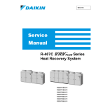
SiE33-201
Service
Manual
R-407C
System
heat pump series
High COP Type L Series
SiE33-201
R-407C
System,
heat pump series
High COP Type, L Series
1. Introduction .............................................................................................v
1.1 Safety Cautions ....................................................................................... v
Part 1 Model Series and Features ................................................1
1. Model Series and Features .....................................................................2
Part 2 Specifications.....................................................................5
1. Specifications ..........................................................................................6
1.1 Outdoor Unit 50Hz................................................................................... 6
1.2 Outdoor Unit 60Hz................................................................................... 9
1.3 Indoor Unit ............................................................................................. 12
Part 3 Function............................................................................31
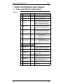
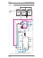
1. Outdoor Unit Refrigerant System Diagram ...........................................32
1.1 Outdoor Unit Refrigerant System Diagram............................................ 32
1.2 Refrigerant flow of different operation mode ......................................... 34
2. Functions...............................................................................................36
2.1 Outdoor unit........................................................................................... 36
3. Outline of Control (Outdoor Unit) ..........................................................47
3.1
3.2
3.3
3.4
3.5
3.6
Restart Standby..................................................................................... 47
Starting control ...................................................................................... 48
Normal Control ...................................................................................... 50
Protection Control.................................................................................. 55
Special Control ...................................................................................... 60
Signal Output Control ............................................................................ 65
4. Outline of Control (Indoor Unit) .............................................................66
4.1
4.2
4.3
4.4
Drain Pump Control ............................................................................... 66
Louver Control for Preventing Ceiling Dirt ............................................. 68
Thermostat Sensor in Remote Controller .............................................. 69
Freeze Prevention ................................................................................. 71
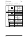
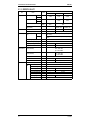
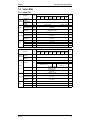
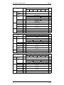
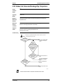
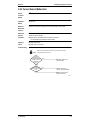
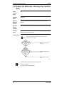
5. List of Electrical and Functional Parts ...................................................72
5.1 Outdoor Unit .......................................................................................... 72
5.2 Indoor Side ............................................................................................ 75
Part 4 Test Operation..................................................................81
1. Test Operation ......................................................................................82
1.1
1.2
1.3
1.4
Table of Contents
Procedure and Outline........................................................................... 82
Operation When Power is Turned On ................................................... 83
Field setting from Outdoor unit .............................................................. 84
Indoor Field Setting ............................................................................... 93
i
SiE33-201
1.5
1.6
1.7
1.8
1.9
1.10
1.11
1.12
1.13
1.14
Cool/Heat Mode Switching .................................................................. 105
Setting of Low Noise Operation and Demand Operation .................... 110
Setting of Refrigerant Additional Charging Operation ......................... 116
Setting of Refrigerant Recovery Mode ................................................ 117
Test Operation..................................................................................... 118
Backup Operation (For 8, 10 HP Types Only)..................................... 119
Emergency Operation (For 8, 10 HP Types Only)............................... 119
Capacity Precedence Operation.......................................................... 119
Fan Intermittent Operation................................................................... 120
Power Transistor Check Operation ..................................................... 120
Part 5 Troubleshooting .............................................................121
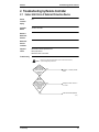
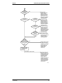
1. Troubleshooting by Remote Controller ...............................................123
1.1
1.2
1.3
1.4
The INSPECTION / TEST Button........................................................ 123
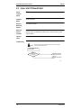
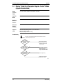
Self-diagnosis by Wired Remote Controller......................................... 124
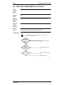
Self-diagnosis by Wireless Remote Controller .................................... 125
Operation of The Remote Controller’s Inspection /
Test Operation Button ......................................................................... 128
1.5 Remote Controller Service Mode ........................................................ 129
1.6 Remote Controller Self-Diagnosis Function ........................................ 131
2. Troubleshooting by Remote Controller ...............................................135
2.1
2.2
2.3
2.4
2.5
2.6
2.7
2.8
2.9
2.10
2.11
2.12
2.13
2.14
2.15
2.16
2.17
2.18
2.19
2.20
2.21
2.22
2.23
2.24
2.25
2.26
2.27
2.28
ii
Indoor Unit: Error of External Protection Device.................................. 135
Indoor Unit: PC Board Defect .............................................................. 136
Indoor Unit: Malfunction of Drain Level Control System (33H)............ 137
Indoor Unit: Fan Motor (M1F) Lock, Overload..................................... 139
Indoor Unit: Malfunction of Swing Flap Motor (MA)............................. 140
Indoor Unit: Malfunction of Moving Part of
Electronic Expansion Valve (20E) ....................................................... 142
Indoor Unit: Drain Level above Limit ................................................... 144
Indoor Unit: Malfunction of Capacity Determination Device ................ 145
Indoor Unit: Malfunction of Thermistor (Th2) for Heat Exchanger....... 146
Indoor Unit: Malfunction of Thermistor (Th3) for Gas Pipes ................ 147
Indoor Unit: Malfunction of Thermistor (Th1) for Suction Air ............... 148
Indoor Unit: Malfunction of Thermostat Sensor in Remote Controller . 149
Outdoor Unit: Actuation of Safety Device ............................................ 150
Outdoor Unit: PC Board Defect ........................................................... 151
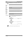
Outdoor Unit: Actuation of High Pressure Switch................................ 152
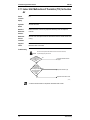
Outdoor Unit: Actuation of Low Pressure Sensor................................ 153
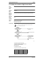
Compressor Motor Lock ...................................................................... 154
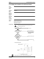
Malfunction of Outdoor Unit Fan Motor ............................................... 155
Outdoor Unit: Malfunction of Moving Part of
Electronic Expansion Valve (Y1E~3E) ................................................ 157
Outdoor Unit: Abnormal Discharge Pipe Temperature........................ 159
Refrigerant Overcharged ..................................................................... 160
Abnormal Outdoor Fan Motor Signal................................................... 161
Outdoor Unit: Malfunction of Thermistor for Outdoor Air (R1T)........... 162
Current Sensor Malfunction................................................................. 163
Outdoor Unit: Malfunction of Discharge Pipe Thermistor (R3T) .......... 164
Outdoor Unit: Malfunction of Thermistor (R4T) for Suction Pipe ......... 165
Outdoor Unit: Malfunction of Thermistor (R2T)
for Outdoor Unit Heat Exchanger ........................................................ 166
Malfunction of Receiver Gas Pipe Thermistor (R5T)........................... 167
Table of Contents
SiE33-201
2.29
2.30
2.31
2.32
2.33
2.34
2.35
2.36
2.37
2.38
2.39
2.40
2.41
2.42
2.43
2.44
2.45
2.46
2.47
2.48
2.49
2.50
2.51
2.52
Outdoor Unit: Malfunction of Discharge Pipe Pressure Sensor........... 168
Outdoor Unit: Malfunction of Suction Pipe Pressure Sensor............... 169
Inverter Box Temperature Rise ........................................................... 170
Outdoor Unit: Malfunction of Inverter Radiating Fin
Temperature Rise................................................................................ 171
Outdoor Unit: Inverter Compressor Abnormal ..................................... 172
Outdoor Unit: Inverter Current Abnormal............................................. 173
Outdoor Unit: Inverter Start up Error ................................................... 174
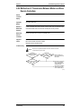
Outdoor Unit: Malfunction of Transmission Between
Inverter and Control PC Board ............................................................ 175
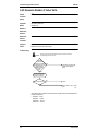
Outdoor Unit: Inverter Over-Ripple Protection..................................... 177
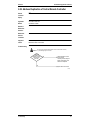
Malfunction of Inverter Box Thermistor................................................ 178
Outdoor Unit: Malfunction of Inverter
Radiating Fin Temperature Rise Sensor ............................................. 179
Low Pressure Drop Due to Refrigerant Shortage or
Electronic Expansion Valve Failure ..................................................... 180
Reverse Phase, Open Phase .............................................................. 181
Power Supply Insufficient or Instantaneous Failure ............................ 182
Malfunction of Transmission Between Indoor Units ............................ 183
Malfunction of Transmission Between Remote Controller
and Indoor Unit .................................................................................... 185
Malfunction of Transmission Between Outdoor Units.......................... 186
Malfunction of Transmission Between Master
and Slave Remote Controllers............................................................. 187
Malfunction of Transmission Between
Indoor and Outdoor Units in the Same System ................................... 188
Excessive Number of Indoor Units ...................................................... 190
Address Duplication of Central Remote Controller.............................. 191
Malfunction of Transmission Between Central Remote Controller
and Indoor Unit .................................................................................... 192
Refrigerant System not Set, Incompatible Wiring/Piping..................... 194
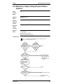
Malfunction of System, Refrigerant System Address Undefined......... 195
3. Troubleshooting (OP: Central Remote Controller) ..............................196
3.1 Malfunction of Transmission Between Central Remote Controller
and Indoor Unit .................................................................................... 196
3.2 PC Board Defect.................................................................................. 197
3.3 Malfunction of Transmission Between Optional Controllers
for Centralized Control......................................................................... 198
3.4 Improper Combination of Optional Controllers
for Centralized Control......................................................................... 199
3.5 Address Duplication, Improper Setting ................................................ 201
4. Troubleshooting (OP: Schedule Timer)...............................................202
4.1 Malfunction of Transmission Between Central Remote Controller
and Indoor Unit .................................................................................... 202
4.2 PC Board Defect.................................................................................. 204
4.3 Malfunction of Transmission Between Optional Controllers
for Centralized Control......................................................................... 205
4.4 Improper Combination of Optional Controllers
for Centralized Control......................................................................... 206
4.5 Address Duplication, Improper Setting ................................................ 208
5. Troubleshooting (OP: Unified ON/OFF Controller) .............................209
5.1 Operation Lamp Blinks ........................................................................ 209
Table of Contents
iii
SiE33-201
5.2 Display “Under Host Computer Integrate Control” Blinks
(Repeats Single Blink) ......................................................................... 211
5.3 Display “Under Host Computer Integrate Control” Blinks
(Repeats Double Blink)........................................................................ 214
Part 6 Appendix.........................................................................215
1. Piping Diagrams..................................................................................216
1.1 Outdoor Unit ........................................................................................ 216
1.2 Indoor Unit ........................................................................................... 218
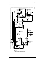
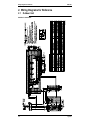
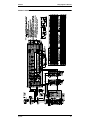
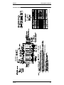
2. Wiring Diagrams for Reference...........................................................220
2.1 Outdoor Unit ........................................................................................ 220
2.2 Indoor Unit ........................................................................................... 222
3. Option List for Outdoor Unit ................................................................235
4. Refrigerant Pipe Fitting Work ..............................................................236
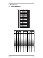
5. Characteristics ....................................................................................237
5.1 R-407C Characteristics ....................................................................... 237
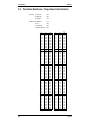
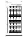
5.2 Thermistor Resistance / Temperature Characteristics ........................ 238
5.3 Pressure Sensor.................................................................................. 240
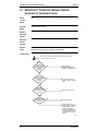
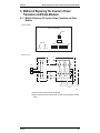
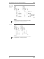
6. Method of Replacing The Inverter’s Power Transistors and Diode
Modules...............................................................................................241
7. Precautions in Servicing The Models with New-type Refrigerant .......243
7.1 Tools Required .................................................................................... 243
7.2 Notes for Work Procedures ................................................................. 244
Index
.............................................................................................i
Drawings & Flow Charts ................................................................ v
iv
Table of Contents
SiE33-201
Introduction
1. Introduction
1.1
Safety Cautions
Cautions and
Warnings
Be sure to read the following safety cautions before conducting repair work.
Warning” and “
Caution”. The “
Warning”
The caution items are classified into “
items are especially important since they can lead to death or serious injury if they are not
Caution” items can also lead to serious accidents under some
followed closely. The “
conditions if they are not followed. Therefore, be sure to observe all the safety caution items
described below.
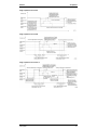
About the pictograms
This symbol indicates an item for which caution must be exercised.
The pictogram shows the item to which attention must be paid.
This symbol indicates a prohibited action.
The prohibited item or action is shown inside or near the symbol.
This symbol indicates an action that must be taken, or an instruction.
The instruction is shown inside or near the symbol.
After the repair work is complete, be sure to conduct a test operation to ensure that the
equipment operates normally, and explain the cautions for operating the product to the
customer
1.1.1 Caution in Repair.
Warning
Be sure to disconnect the power cable plug from the plug socket before
disassembling the equipment for a repair.
Working on the equipment that is connected to a power supply can cause an
electrical shook.
If it is necessary to supply power to the equipment to conduct the repair or
inspecting the circuits, do not touch any electrically charged sections of the
equipment.
If the refrigerant gas discharges during the repair work, do not touch the
discharging refrigerant gas.
The refrigerant gas can cause frostbite.
When disconnecting the suction or discharge pipe of the compressor at the
welded section, release the refrigerant gas completely at a well-ventilated
place first.
If there is a gas remaining inside the compressor, the refrigerant gas or
refrigerating machine oil discharges when the pipe is disconnected, and it can
cause injury.
If the refrigerant gas leaks during the repair work, ventilate the area. The
refrigerant gas can generate toxic gases when it contacts flames.
The step-up capacitor supplies high-voltage electricity to the electrical
components of the outdoor unit.
Be sure to discharge the capacitor completely before conducting repair work.
A charged capacitor can cause an electrical shock.
Do not start or stop the air conditioner operation by plugging or unplugging the
power cable plug.
Plugging or unplugging the power cable plug to operate the equipment can
cause an electrical shock or fire.
v
Introduction
SiE33-201
Caution
Do not repair the electrical components with wet hands.
Working on the equipment with wet hands can cause an electrical shock.
Do not clean the air conditioner by splashing water.
Washing the unit with water can cause an electrical shock.
Be sure to provide the grounding when repairing the equipment in a humid or
wet place, to avoid electrical shocks.
Be sure to turn off the power switch and unplug the power cable when cleaning
the equipment.
The internal fan rotates at a high speed, and cause injury.
Do not tilt the unit when removing it.
The water inside the unit can spill and wet the furniture and floor.
Be sure to check that the refrigerating cycle section has cooled down
sufficiently before conducting repair work.
Working on the unit when the refrigerating cycle section is hot can cause burns.
Use the welder in a well-ventilated place.
Using the welder in an enclosed room can cause oxygen deficiency.
1.1.2 Cautions Regarding Products after Repair
Warning
Be sure to use parts listed in the service parts list of the applicable model and
appropriate tools to conduct repair work. Never attempt to modify the
equipment.
The use of inappropriate parts or tools can cause an electrical shock,
excessive heat generation or fire.
When relocating the equipment, make sure that the new installation site has
sufficient strength to withstand the weight of the equipment.
If the installation site does not have sufficient strength and if the installation
work is not conducted securely, the equipment can fall and cause injury.
Be sure to install the product correctly by using the provided standard
installation frame.
Incorrect use of the installation frame and improper installation can cause the
equipment to fall, resulting in injury.
Be sure to install the product securely in the installation frame mounted on a
window frame.
If the unit is not securely mounted, it can fall and cause injury.
Be sure to use an exclusive power circuit for the equipment, and follow the
technical standards related to the electrical equipment, the internal wiring
regulations and the instruction manual for installation when conducting
electrical work.
Insufficient power circuit capacity and improper electrical work can cause an
electrical shock or fire.
vi
For integral units
only
For integral units
only
SiE33-201
Introduction
Warning
Be sure to use the specified cable to connect between the indoor and outdoor
units. Make the connections securely and route the cable properly so that there
is no force pulling the cable at the connection terminals.
Improper connections can cause excessive heat generation or fire.
When connecting the cable between the indoor and outdoor units, make sure
that the terminal cover does not lift off or dismount because of the cable.
If the cover is not mounted properly, the terminal connection section can cause
an electrical shock, excessive heat generation or fire.
Do not damage or modify the power cable.
Damaged or modified power cable can cause an electrical shock or fire.
Placing heavy items on the power cable, and heating or pulling the power cable
can damage the cable.
Do not mix air or gas other than the specified refrigerant (R-407C) in the
refrigerant system.
If air enters the refrigerating system, an excessively high pressure results,
causing equipment damage and injury.
If the refrigerant gas leaks, be sure to locate the leak and repair it before
charging the refrigerant. After charging refrigerant, make sure that there is no
refrigerant leak.
If the leak cannot be located and the repair work must be stopped, be sure to
perform pump-down and close the service valve, to prevent the refrigerant gas
from leaking into the room. The refrigerant gas itself is harmless, but it can
generate toxic gases when it contacts flames, such as fan and other heaters,
stoves and ranges.
When replacing the coin battery in the remote controller, be sure to disposed
of the old battery to prevent children from swallowing it.
If a child swallows the coin battery, see a doctor immediately.
Caution
Installation of a leakage breaker is necessary in some cases depending on the
conditions of the installation site, to prevent electrical shocks.
Do not install the equipment in a place where there is a possibility of
combustible gas leaks.
If a combustible gas leaks and remains around the unit, it can cause a fire.
Be sure to install the packing and seal on the installation frame properly.
For integral units
If the packing and seal are not installed properly, water can enter the room and only
wet the furniture and floor.
1.1.3 Inspection after Repair
Warning
Check to make sure that the power cable plug is not dirty or loose, then insert
the plug into a power outlet all the way.
If the plug has dust or loose connection, it can cause an electrical shock or fire.
If the power cable and lead wires have scratches or deteriorated, be sure to
replace them.
Damaged cable and wires can cause an electrical shock, excessive heat
generation or fire.
Do not use a joined power cable or extension cable, or share the same power
outlet with other electrical appliances, since it can cause an electrical shock,
excessive heat generation or fire.
vii
Introduction
SiE33-201
Caution
Check to see if the parts and wires are mounted and connected properly, and
if the connections at the soldered or crimped terminals are secure.
Improper installation and connections can cause excessive heat generation,
fire or an electrical shock.
If the installation platform or frame has corroded, replace it.
Corroded installation platform or frame can cause the unit to fall, resulting in
injury.
Check the grounding, and repair it if the equipment is not properly grounded.
Improper grounding can cause an electrical shock.
Be sure to measure the insulation resistance after the repair, and make sure
that the resistance is 1 Mohm or higher.
Faulty insulation can cause an electrical shock.
Be sure to check the drainage of the indoor unit after the repair.
Faulty drainage can cause the water to enter the room and wet the furniture
and floor.
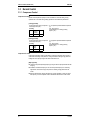
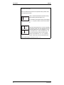
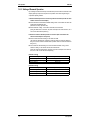
1.1.4 Using Icons
Icons are used to attract the attention of the reader to specific information. The meaning of each
icon is described in the table below:
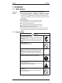
1.1.5 Using Icons List
Icon
Type of
Information
Note
Description
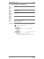
Caution
A “caution” is used when there is danger that the reader, through
incorrect manipulation, may damage equipment, loose data, get
an unexpected result or has to restart (part of) a procedure.
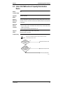
Warning
A “warning” is used when there is danger of personal injury.
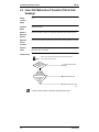
Reference
A “reference” guides the reader to other places in this binder or
in this manual, where he/she will find additional information on a
specific topic.
A “note” provides information that is not indispensable, but may
nevertheless be valuable to the reader, such as tips and tricks.
Note:
Caution
Warning
viii
SiE33-201
Part 1
Model Series and Features
1. Model Series and Features .....................................................................2
Model Series and Features
1
Model Series and Features
SiE33-201
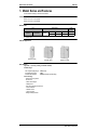
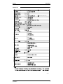
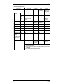
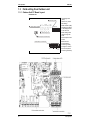
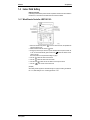
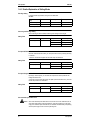
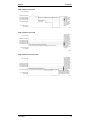
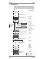
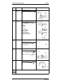
1. Model Series and Features
The informations including in this book are as follows.
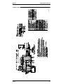
Outdoor Units
RSXYP 5LY1, 8LY1, 10LY1 (50Hz)
RSXYP 5LYL, 8LYL, 10LYL (60Hz)
Model Series
Type
Inverter
Model Name
Heat Pump
RSXYP
5L
5L
8L
8L
Power
Supply
10L
10L
Y1
YL
Y1 : 3φ 380V-415V, 50Hz
YL : 3φ 380V, 60Hz
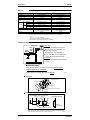
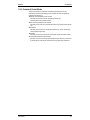
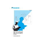
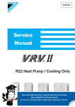
External Appearance
RSXYP5L (5HP)
RSXYP8L (8HP)
RSXYP10L (10HP)
Main Features
*High COP : 3.1 (Cooling / Heating in standard condition)
*Flexible design :
Max. refrigerant piping length : 120m (Actual)
Equivalent piping length
: 140m
External Static Pressure
: 6mmH2O (Standard by field setting)
*New technology :
- Reluctance DC compressor
- DC fan motor
- e-Pass heat exchanger
- e-Bridge circuit
- Super aero grille and powerful let fan
- Low sound function
- i-demand function
- i-Touch Controller
- intelligent Manager ECO21
2
Model Series and Features
SiE33-201
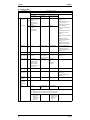
Model Series and Features
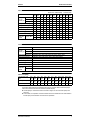
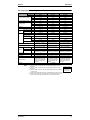
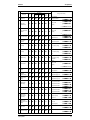
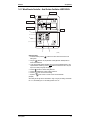
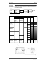
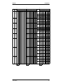
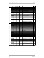
Indoor Unit model Series
Type
P20
Ceiling
Multi-flow type
—
mounted
Double-flow
type
cassette type
Corner type
—
Ceiling mounted built-in type
Ceiling mounted duct type
—
Ceiling suspended type
—
Wall mounted type
Floor standing type
Concealed floor standing type
New Ceiling
—
suspended
FUYP +BEV
—
cassette
Type
P25
—
—
—
Type
P32
—
—
Type
P40
—
—
—
—
—
New model Model change Continued model
Type Type Type Type Type Type Type Type
P50
P63
P71
P80 P100 P125 P200 P250
—
—
—
—
—
—
—
—
—
—
—
—
—
—
—
—
—
—
—
—
—
—
—
—
—
—
—
—
—
—
—
—
—
—
—
—
—
—
—
—
—
—
—
—
—
—
—
—
—
—
—
—
Connection Unit (BEV-K) is necessary.
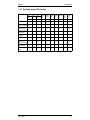
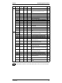
Connectable indoor unit
Indoor unit
Multi-flow type
Model name
Ceiling
FXF25LVE, 32LVE, 40LVE, 50LVE, 63LVE, 80LVE, 100LVE, 125LVE
mounted
Double flow type FXYCP20KV1·25KV1·32KV1·40KV1·50KV1·63KV1·80KV1·125KV1
cassette type
Corner type
FXYKP25KV1·32KV1·40KV1·63KV1
Ceiling mounted built-in type
FXYSP20KV1·25KV1·32KV1·40KV1·50KV1·63KV1·80KV1·100KV1·125KV1
Ceiling mounted duct type
FXYMP40KV1·50KV1·63KV1·80KV1·100KV1·125KV1·200KV1·250KV1
Ceiling suspended type
FXYHP32KVE·63KVE·100KVE
Wall mounted type
FXYAP20KV1·25KV1·32KV1·40KV1·50KV1·63KV1
Floor standing type
FXYLP20KV1·25KV1·32KV1·40KV1·50KV1·63KV1
Concealed floor standing type FXYLMP20KV1·25KV1·32KV1·40KV1·50KV1·63KV1
New Ceiling FUYP
FUYP71BV1, 100BV1, 125BV1
suspended
BEV
BEV71KVE, 140KVE
cassette
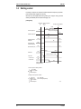
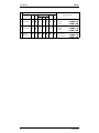
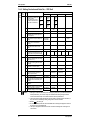
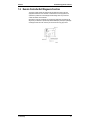
Indoor unit capacity
New refrigerant model
code
Selecting model capacity
Equivalent output
P20
type
2.2
kW
0.8HP
P25
type
2.8
kW
1HP
P32
type
3.5
kW
P40
type
4.5
kW
P50
type
5.6
kW
P63
type
7.0
kW
P71
type
8.0
kW
P80
type
9.0
kW
1.25HP 1.6HP 2.0HP 2.5HP 3.0HP 3.2HP
P100
type
11.2
kW
P125
type
14.0
kW
P200
type
22.4
kW
P250
type
28.0
kW
4HP
5HP
8HP
10HP
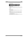
Use the above tables to determine the capacities of indoor units to be connected. Make sure the total capacity of
indoor units connected to each outdoor unit is within the specified value (kW).
The total capacity of connected indoor units must be within a range of 50 to 130% of the rated capacity of the
outdoor unit.
In some models, it is not possible to connect the maximum number of connectable indoor units. Select models so
the total capacity of connected indoor units conforms to the specification.
Model Series and Features
3
Model Series and Features
4
SiE33-201
Model Series and Features
SiE33-201
Part 2
Specifications
1. Specifications ..........................................................................................6
1.1 Outdoor Unit 50Hz................................................................................... 6
1.2 Outdoor Unit 60Hz................................................................................... 9
1.3 Indoor Unit ............................................................................................. 12
Specifications
5
Specifications
SiE33-201
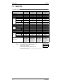
1. Specifications
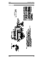
1.1
Outdoor Unit 50Hz
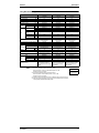
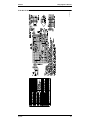
RSXYP5LY1(E)
R S X Y P 5 LY 1 E
Light camel (2.5Y6.5/1.5)
fan driver overload protector,
7.5m
7.5m
4D031694
6
Specifications
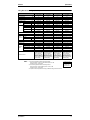
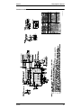
SiE33-201
Specifications
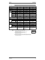
RSXYP8LY1(E)
R S X Y P 8 LY 1 E
Light camel (2.5Y6.5/1.5)
25.4
fan moter overload protection,
7.5m
7.5m
4D031984
Specifications
7
Specifications
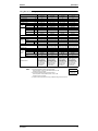
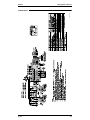
SiE33-201
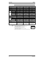
RSXYP10LY1(E)
R S X Y P 1 0 LY 1 E
Light camel (2.5Y6.5/1.5)
fan driver overload protector,
7.5m
7.5m
4D031985
8
Specifications
SiE33-201
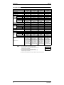
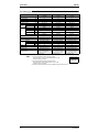
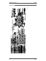
1.2
Specifications
Outdoor Unit 60Hz
RSXYP5LYL(E)
4D034040
Specifications
9
Specifications
SiE33-201
RSXYP8LYL(E)
4D034041
10
Specifications
SiE33-201
Specifications
RSXYP10LYL(E)
4D034042
Specifications
11
Specifications
1.3
SiE33-201
Indoor Unit
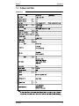
Ceiling Mounted Cassette Type (Multi-flow)
Model
Power Supply
1 Cooling Capacity
2 Heating Capacity
Casing
Dimensions: (H×W×D)
Rows×Stages×Fin Pitch
Coil (Cross
Fin Coil)
Face Area
Model
Type
Motor Output × Number
Fan
of Units
Air Flow Rate (H/L)
Drive
kW
kW
mm
mm
m²
Standard Accessories
Notes:
12
FXF40LVE
FXF50LVE
1 phase 50/60Hz
220~240V/220V
4.5
5.0
Galvanized Steel Plate
246×840×840
2×8×1.2
0.363
QTS46D14M
Turbo Fan
1 phase 50/60Hz
220~240V/220V
5.6
6.3
Galvanized Steel Plate
246×840×840
2×8×1.2
0.363
QTS46D14M
Turbo Fan
W
30
30
30
30
13/10
Direct Drive
Microprocessor Thermostat
for Cooling and Heating
Polyurethane form
6.4mm (Flare Connection)
12.7mm (Flare Connection)
VP25 (External Dia. 32
Internal Dia. 25)
24
Fuse
Electronic Expansion Valve
BYCP125D-W1
White
45×950×950
Resin Net
(with Mold Resistant)
5.5
Operation Manual,
Installation Manual, Paper
Pattern for Installation,
Drain Hose, Clamp metal,
Washer fixing plate, Sealing
pads, Clamps, Screws,
Washer for hanging bracket,
Insulation for fitting.
15/11
Direct Drive
Microprocessor Thermostat
for Cooling and Heating
Polyurethane form
6.4mm (Flare Connection)
12.7mm (Flare Connection)
VP25 (External Dia. 32
Internal Dia. 25)
24
Fuse
Electronic Expansion Valve
BYCP125D-W1
White
45×950×950
Resin Net
(with Mold Resistant)
5.5
Operation Manual,
Installation Manual, Paper
Pattern for Installation,
Drain Hose, Clamp metal,
Washer fixing plate, Sealing
pads, Clamps, Screws,
Washer for hanging bracket,
Insulation for fitting.
16/11
Direct Drive
Microprocessor Thermostat
for Cooling and Heating
Polyurethane form
9.5mm (Flare Connection)
15.9mm (Flare Connection)
VP25 (External Dia. 32
Internal Dia. 25)
24
Fuse
Electronic Expansion Valve
BYCP125D-W1
White
45×950×950
Resin Net
(with Mold Resistant)
5.5
Operation Manual,
Installation Manual, Paper
Pattern for Installation,
Drain Hose, Clamp metal,
Washer fixing plate, Sealing
pads, Clamps, Screws,
Washer for hanging bracket,
Insulation for fitting.
Sound Absorbing Thermal Insulation Material
Liquid Pipes
Piping
Gas Pipes
Connections
Drain Pipe
(mm)
Weight
FXF32LVE
1 phase 50/60Hz
220~240V/220V
3.6
4.0
Galvanized Steel Plate
246×840×840
2×8×1.2
0.363
QTS46D14M
Turbo Fan
m³/min
Temperature Control
Weight
Safety Devices
Refrigerant Control
Mode
Panel Color
Decoration
Dimensions: (H×W×D)
Panels
Air Filter
FXF25LVE
1 phase 50/60Hz
220~240V/220V
2.8
3.2
Galvanized Steel Plate
246×840×840
2×8×1.2
0.363
QTS46D14M
Turbo Fan
kg
mm
kg
1 Nominal cooling capacities are based on the following conditions:
Return air temperature : 27˚C DB, 19˚C WB, Outdoor temperature : 35˚C DB
Equivalent ref. piping : 7.5m (Horizontal)
2 Nominal heating capacities are based on the following conditions:
Return air temperature : 20˚C DB, Outdoor temperature : 7˚C DB, 6˚C WB
Equivalent ref. piping : 7.5m (Horizontal)
3 Capacities are net, including a deduction for cooling (an addition for heating) for indoor fan motor heat.
Conversion Formulae
kcal/h=kW×860
Btu/h=kW×3414
cfm=m³/min×35.3
Specifications
SiE33-201
Specifications
Ceiling Mounted Cassette Type (Multi-flow)
Model
Power Supply
1 Cooling Capacity
2 Heating Capacity
Casing
Dimensions: (H×W×D)
Rows×Stages×Fin Pitch
Coil (Cross
Fin Coil)
Face Area
Model
Type
Motor Output × Number
Fan
of Units
Air Flow Rate (H/L)
Drive
kW
kW
mm
mm
m²
Standard Accessories
Notes:
Specifications
FXF100LVE
FXF125LVE
1 phase 50/60Hz
220~240V/220V
11.2
12.5
Galvanized Steel Plate
288×840×840
2×12×1.2
0.544
QTS46C17M
Turbo Fan
1 phase 50/60Hz
220~240V/220V
14.0
16.0
Galvanized Steel Plate
288×840×840
2×12×1.2
0.544
QTS46C17M
Turbo Fan
W
30
30
120
120
18.5/14
Direct Drive
Microprocessor Thermostat
for Cooling and Heating
Polyurethane form
9.5mm (Flare Connection)
15.9mm (Flare Connection)
VP25 (External Dia. 32
Internal Dia. 25)
25
Fuse
Electronic Expansion Valve
BYCP125D-W1
White
45×950×950
Resin Net
(with Mold Resistant)
5.5
Operation Manual,
Installation Manual, Paper
Pattern for Installation,
Drain Hose, Clamp metal,
Washer fixing plate, Sealing
pads, Clamps, Screws,
Washer for hanging bracket,
Insulation for fitting.
20/15
Direct Drive
Microprocessor Thermostat
for Cooling and Heating
Polyurethane form
9.5mm (Flare Connection)
15.9mm (Flare Connection)
VP25 (External Dia. 32
Internal Dia. 25)
25
Fuse
Electronic Expansion Valve
BYCP125D-W1
White
45×950×950
Resin Net
(with Mold Resistant)
5.5
Operation Manual,
Installation Manual, Paper
Pattern for Installation,
Drain Hose, Clamp metal,
Washer fixing plate, Sealing
pads, Clamps, Screws,
Washer for hanging bracket,
Insulation for fitting.
26/21
Direct Drive
Microprocessor Thermostat
for Cooling and Heating
Polyurethane form
9.5mm (Flare Connection)
19.1mm (Flare Connection)
VP25 (External Dia. 32
Internal Dia. 25)
29
Fuse
Electronic Expansion Valve
BYCP125D-W1
White
45×950×950
Resin Net
(with Mold Resistant)
5.5
Operation Manual,
Installation Manual, Paper
Pattern for Installation,
Drain Hose, Clamp metal,
Washer fixing plate, Sealing
pads, Clamps, Screws,
Washer for hanging bracket,
Insulation for fitting.
30/24
Direct Drive
Microprocessor Thermostat
for Cooling and Heating
Polyurethane form
9.5mm (Flare Connection)
19.1mm (Flare Connection)
VP25 (External Dia. 32
Internal Dia. 25)
29
Fuse
Electronic Expansion Valve
BYCP125D-W1
White
45×950×950
Resin Net
(with Mold Resistant)
5.5
Operation Manual,
Installation Manual, Paper
Pattern for Installation,
Drain Hose, Clamp metal,
Washer fixing plate, Sealing
pads, Clamps, Screws,
Washer for hanging bracket,
Insulation for fitting.
Sound Absorbing Thermal Insulation Material
Liquid Pipes
Piping
Gas Pipes
Connections
Drain Pipe
(mm)
Weight
FXF80LVE
1 phase 50/60Hz
220~240V/220V
9.0
10.0
Galvanized Steel Plate
246×840×840
2×10×1.2
0.454
QTS46D14M
Turbo Fan
m³/min
Temperature Control
Weight
Safety Devices
Refrigerant Control
Mode
Panel Color
Decoration
Dimensions: (H×W×D)
Panels
Air Filter
FXF63LVE
1 phase 50/60Hz
220~240V/220V
7.1
8.0
Galvanized Steel Plate
246×840×840
2×10×1.2
0.454
QTS46D14M
Turbo Fan
kg
mm
kg
1 Nominal cooling capacities are based on the following conditions:
Return air temperature : 27˚C DB, 19˚C WB, Outdoor temperature : 35˚C DB
Equivalent ref. piping : 7.5m (Horizontal)
2 Nominal heating capacities are based on the following conditions:
Return air temperature : 20˚C DB, Outdoor temperature : 7˚C DB, 6˚C WB
Equivalent ref. piping : 7.5m (Horizontal)
3 Capacities are net, including a deduction for cooling (an addition for heating) for indoor fan motor heat.
Conversion Formulae
kcal/h=kW×860
Btu/h=kW×3414
cfm=m³/min×35.3
13
Specifications
SiE33-201
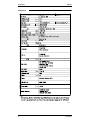
Ceiling Mounted Cassette Type (Double-flow)
Model
Power Supply
1 Cooling Capacity
2 Heating Capacity
Casing
Dimensions: (H×W×D)
Rows×Stages×Fin Pitch
Coil (Cross
Fin Coil)
Face Area
Model
Type
Motor Output × Number
Fan
of Units
Air Flow Rate (H/L)
Drive
kW
kW
mm
mm
m²
1 phase 50Hz
220-240V
4.5
5.0
Galvanized Steel Plate
305×995×600
2×10×1.5
2×0.145
2D17K1AA1
Sirocco Fan
10
15
15
20
9/6.5
Direct Drive
Microprocessor Thermostat
for Cooling and Heating
Glass Wool/Urethane Foam
6.4mm (Flare Connection)
12.7mm (Flare Connection)
VP25 (External Dia. 32
Internal Dia. 25)
26
Fuse
Thermal Fuse for Fan Motor
Electronic Expansion Valve
BYBC32GJW1
White (10Y9/0.5)
53×1,030×680
Resin Net
(with Mold Resistant)
8
Operation Manual,
Installation Manual, Paper
Pattern for Installation,
Drain Hose, Washer for
Heating Brackets, Clamp
Metal, Insulation for Fitting,
Washer Fixing Plates,
Sealing Pads, Clamps,
Screws, Washers.
12/9
Direct Drive
Microprocessor Thermostat
for Cooling and Heating
Glass Wool/Urethane Foam
6.4mm (Flare Connection)
12.7mm (Flare Connection)
VP25 (External Dia. 32
Internal Dia. 25)
31
Fuse
Thermal Fuse for Fan Motor
Electronic Expansion Valve
BYBC50GJW1
White (10Y9/0.5)
53×1,245×680
Resin Net
(with Mold Resistant)
8.5
Operation Manual,
Installation Manual, Paper
Pattern for Installation,
Drain Hose, Washer for
Heating Brackets, Clamp
Metal, Insulation for Fitting,
Washer Fixing Plates,
Sealing Pads, Clamps,
Screws, Washers.
kg
Standard Accessories
FXYCP40KV1
1 phase 50Hz
220-240V
3.6
4.0
Galvanized Steel Plate
305×780×600
2×10×1.5
2×0.100
D17K2AB1
Sirocco Fan
7/5
Direct Drive
Microprocessor Thermostat
for Cooling and Heating
Glass Wool/Urethane Foam
6.4mm (Flare Connection)
12.7mm (Flare Connection)
VP25 (External Dia. 32
Internal Dia. 25)
26
Fuse
Thermal Fuse for Fan Motor
Electronic Expansion Valve
BYBC32GJW1
White (10Y9/0.5)
53×1,030×680
Resin Net
(with Mold Resistant)
8
Operation Manual,
Installation Manual, Paper
Pattern for Installation,
Drain Hose, Washer for
Heating Brackets, Clamp
Metal, Insulation for Fitting,
Washer Fixing Plates,
Sealing Pads, Clamps,
Screws, Washers.
Safety Devices
Weight
FXYCP32KV1
1 phase 50Hz
220-240V
2.8
3.2
Galvanized Steel Plate
305×780×600
2×10×1.5
2×0.100
D17K2AB1
Sirocco Fan
W
Sound Absorbing Thermal Insulation Material
Liquid Pipes
Piping
Gas Pipes
Connections
Drain Pipe
(mm)
Refrigerant Control
Model
Panel Color
Decoration
Dimensions: (H×W×D)
Panels
Air Filter
FXYCP25KV1
1 phase 50Hz
220-240V
2.2
2.5
Galvanized Steel Plate
305×780×600
2×10×1.5
2×0.100
D17K2AA1
Sirocco Fan
m³/min
Temperature Control
Weight
FXYCP20KV1
mm
kg
Drawing No.
Notes:
14
1 Nominal cooling capacities are based on the following conditions:
Return air temperature : 27˚C DB, 19˚C WB, Outdoor temperature : 35˚C DB
Equivalent ref. piping : 5m (Horizontal)
2 Nominal heating capacities are based on the following conditions:
Return air temperature : 20˚C DB, Outdoor temperature : 7˚C DB, 6˚C WB
Equivalent ref. piping : 5m (Horizontal)
3 Capacities are net, including a deduction for cooling (an addition for heating) for indoor fan motor heat.
Conversion Formulae
kcal/h=kW×860
Btu/h=kW×3414
cfm=m³/min×35.3
Specifications
SiE33-201
Specifications
Ceiling Mounted Cassette Type (Double-flow)
Model
Power Supply
1 Cooling Capacity
2 Heating Capacity
Casing
Dimensions: (H×W×D)
Rows×Stages×Fin Pitch
Coil (Cross
Fin Coil)
Face Area
Model
Type
Motor Output × Number
Fan
of Units
Air Flow Rate (H/L)
Drive
kW
kW
mm
mm
m²
Notes:
Specifications
1 phase 50Hz
220-240V
14.0
16.0
Galvanized Steel Plate
305×1,670×600
2×10×1.5
2×0.287
3D17K2AB1
Sirocco Fan
20
30
50
85
16.5/13
Direct Drive
Microprocessor Thermostat
for Cooling and Heating
Glass Wool/Urethane Foam
9.5mm (Flare Connection)
15.9mm (Flare Connection)
VP25 (External Dia. 32
Internal Dia. 25)
35
Fuse
Thermal Fuse for Fan Motor
Electronic Expansion Valve
BYBC63GJW1
White (10Y9/0.5)
53×1,430×680
Resin Net
(with Mold Resistant)
9.5
Operation Manual,
Installation Manual, Paper
Pattern for Installation,
Drain Hose, Washer for
Heating Brackets, Clamp
Metal, Insulation for Fitting,
Washer Fixing Plates,
Sealing Pads, Clamps,
Screws, Washers.
26/21
Direct Drive
Microprocessor Thermostat
for Cooling and Heating
Glass Wool/Urethane Foam
9.5mm (Flare Connection)
15.9mm (Flare Connection)
VP25 (External Dia. 32
Internal Dia. 25)
47
Fuse
Thermal Fuse for Fan Motor
Electronic Expansion Valve
BYBC125GJW1
White (10Y9/0.5)
53×1,920×680
Resin Net
(with Mold Resistant)
12
Operation Manual,
Installation Manual, Paper
Pattern for Installation,
Drain Hose, Washer for
Heating Brackets, Clamp
Metal, Insulation for Fitting,
Washer Fixing Plates,
Sealing Pads, Clamps,
Screws, Washers.
33/25
Direct Drive
Microprocessor Thermostat
for Cooling and Heating
Glass Wool/Urethane Foam
9.5mm (Flare Connection)
19.1mm (Flare Connection)
VP25 (External Dia. 32
Internal Dia. 25)
48
Fuse
Thermal Fuse for Fan Motor
Electronic Expansion Valve
BYBC125GJW1
White (10Y9/0.5)
53×1,920×680
Resin Net
(with Mold Resistant)
12
Operation Manual,
Installation Manual, Paper
Pattern for Installation,
Drain Hose, Washer for
Heating Brackets, Clamp
Metal, Insulation for Fitting,
Washer Fixing Plates,
Sealing Pads, Clamps,
Screws, Washers.
kg
Standard Accessories
FXYCP125KV1
1 phase 50Hz
220-240V
9.0
10.0
Galvanized Steel Plate
305×1,670×600
2×10×1.5
2×0.287
3D17K2AA1
Sirocco Fan
12/9
Direct Drive
Microprocessor Thermostat
for Cooling and Heating
Glass Wool/Urethane Foam
9.5mm (Flare Connection)
15.9mm (Flare Connection)
VP25 (External Dia. 32
Internal Dia. 25)
32
Fuse
Thermal Fuse for Fan Motor
Electronic Expansion Valve
BYBC50GJW1
White (10Y9/0.5)
53×1,245×680
Resin Net
(with Mold Resistant)
8.5
Operation Manual,
Installation Manual, Paper
Pattern for Installation,
Drain Hose, Washer for
Heating Brackets, Clamp
Metal, Insulation for Fitting,
Washer Fixing Plates,
Sealing Pads, Clamps,
Screws, Washers.
Safety Devices
Weight
FXYCP80KV1
1 phase 50Hz
220-240V
7.1
8.0
Galvanized Steel Plate
305×1,180×600
2×10×1.5
2×0.184
2D17K2AA1VE
Sirocco Fan
W
Sound Absorbing Thermal Insulation Material
Liquid Pipes
Piping
Gas Pipes
Connections
Drain Pipe
(mm)
Refrigerant Control
Model
Panel Color
Decoration
Dimensions: (H×W×D)
Panels
Air Filter
FXYCP63KV1
1 phase 50Hz
220-240V
5.6
6.3
Galvanized Steel Plate
305×995×600
2×10×1.5
2×0.145
2D17K1AA1
Sirocco Fan
m³/min
Temperature Control
Weight
FXYCP50KV1
mm
kg
1 Nominal cooling capacities are based on the following conditions:
Return air temperature : 27˚C DB, 19˚C WB, Outdoor temperature : 35˚C DB
Equivalent ref. piping : 5m (Horizontal)
2 Nominal heating capacities are based on the following conditions:
Return air temperature : 20˚C DB, Outdoor temperature : 7˚C DB, 6˚C WB
Equivalent ref. piping : 5m (Horizontal)
3 Capacities are net, including a deduction for cooling (an addition for heating) for indoor fan motor heat.
Conversion Formulae
kcal/h=kW×860
Btu/h=kW×3414
cfm=m³/min×35.3
15
Specifications
SiE33-201
Ceiling Mounted Cassette Corner Type
Model
FXYKP25KV1
FXYKP32KV1
FXYKP40KV1
FXYKP63KV1
1 phase 50Hz
220-240V
2.8
3.2
Galvanized Steel Plate
215×1,110×710
2×11×1.75
0.180
3D12H1AN1V1
Sirocco Fan
1 phase 50Hz
220-240V
3.6
4.0
Galvanized Steel Plate
215×1,110×710
2×11×1.75
0.180
3D12H1AN1V1
Sirocco Fan
1 phase 50Hz
220-240V
4.5
5.0
Galvanized Steel Plate
215×1,110×710
2×11×1.75
0.180
3D12H1AP1V1
Sirocco Fan
1 phase 50Hz
220-240V
7.1
8.0
Galvanized Steel Plate
215×1,310×710
3×11×1.75
0.226
4D12H1AJ1V1
Sirocco Fan
W
15×1
15×1
20×1
45×1
m³/min
11/9
Direct Drive
Microprocessor Thermostat
for Cooling and Heating
Polyethylene Foam
6.4mm (Flare Connection)
12.7mm (Flare Connection)
VP25 (External Dia. 32
Internal Dia. 25)
31
Fuse
Thermal Fuse for Fan Motor
Electronic Expansion Valve
BYK45FJW1
White
70×1,240×800
Resin Net
(with Mold Resistant)
8.5
Operation Manual,
Installation Manual, Paper
Pattern for Installation,
Drain Hose, Clamp Metal,
Insulation for Fitting, Sealing
Pads, Clamps, Screws,
Washers, Positioning Jig for
Installation, Insulation for
Hanger Bracket, Drain Pipe
Insulation, Air Outlet
Blocking Pad, Drain Raising
Pipe.
13/10
Direct Drive
Microprocessor Thermostat
for Cooling and Heating
Polyethylene Foam
6.4mm (Flare Connection)
12.7mm (Flare Connection)
VP25 (External Dia. 32
Internal Dia. 25)
31
Fuse
Thermal Fuse for Fan Motor
Electronic Expansion Valve
BYK45FJW1
White
70×1,240×800
Resin Net
(with Mold Resistant)
8.5
Operation Manual,
Installation Manual, Paper
Pattern for Installation,
Drain Hose, Clamp Metal,
Insulation for Fitting, Sealing
Pads, Clamps, Screws,
Washers, Positioning Jig for
Installation, Insulation for
Hanger Bracket, Drain Pipe
Insulation, Air Outlet
Blocking Pad, Drain Raising
Pipe.
18/15
Direct Drive
Microprocessor Thermostat
for Cooling and Heating
Polyethylene Foam
9.5mm (Flare Connection)
15.9mm (Flare Connection)
VP25 (External Dia. 32
Internal Dia. 25)
34
Fuse
Thermal Fuse for Fan Motor
Electronic Expansion Valve
BYK71FJW1
White
70×1,440×800
Resin Net
(with Mold Resistant)
9.5
Operation Manual,
Installation Manual, Paper
Pattern for Installation,
Drain Hose, Clamp Metal,
Insulation for Fitting, Sealing
Pads, Clamps, Screws,
Washers, Positioning Jig for
Installation, Insulation for
Hanger Bracket, Drain Pipe
Insulation, Air Outlet
Blocking Pad, Drain Raising
Pipe.
Power Supply
1 Cooling Capacity
2 Heating Capacity
Casing
Dimensions: (H×W×D)
Rows×Stages×Fin Pitch
Coil (Cross
Fin Coil)
Face Area
Model
Type
Motor Output × Number
Fan
of Units
Air Flow Rate (H/L)
Drive
kW
kW
mm
mm
m²
V1
Temperature Control
Sound Absorbing Thermal Insulation Material
Liquid Pipes
Piping
Gas Pipes
Connections
Drain Pipe
(mm)
Weight
kg
Safety Devices
Refrigerant Control
Model
Panel Color
Decoration
Dimensions: (H×W×D)
Panels
Air Filter
Weight
Standard Accessories
Notes:
16
mm
kg
1 Nominal cooling capacities are based on the following conditions:
Return air temperature : 27˚C DB, 19˚C WB, Outdoor temperature : 35˚C DB
Equivalent ref. piping : 5m (Horizontal)
2 Nominal heating capacities are based on the following conditions:
Return air temperature : 20˚C DB, Outdoor temperature : 7˚C DB, 6˚C WB
Equivalent ref. piping : 5m (Horizontal)
3 Capacities are net, including a deduction for cooling (an addition for heating) for indoor fan motor heat.
Conversion Formulae
kcal/h=kW×860
Btu/h=kW×3414
cfm=m³/min×35.3
Specifications
SiE33-201
Specifications
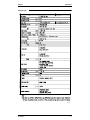
Ceiling Mounted Built-in Type
Model
Power Supply
1 Cooling Capacity
2 Heating Capacity
Casing
Dimensions: (H×W×D)
Rows×Stages×Fin Pitch
Coil (Cross
Fin Coil)
Face Area
Model
Fan
Type
Motor Output × Number
of Units
Air Flow Rate (H/L)
4 External Static
Pressure (50/60Hz)
Drive
kW
kW
mm
mm
m²
V1
VAL
50×1
50×1
50×1
9/6.5
9.5/7
Pa
kg
Notes:
Specifications
1 phase 50Hz
220-240V
3.6
4.0
Galvanized Steel Plate
300×550×800
3×14×1.75
0.088
D18H3AA1V1
D18H3AA1
Sirocco Fan
9/6.5
Safety Devices
Standard Accessories
FXYSP32KV1
1 phase 50Hz
220-240V
2.8
3.2
Galvanized Steel Plate
300×550×800
3×14×1.75
0.088
D18H3AA1V1
D18H3AA1
Sirocco Fan
W
Sound Absorbing Thermal Insulation Material
Air Filter
Liquid Pipes
Piping
Gas Pipes
Connections
Drain Pipe
(mm)
Refrigerant Control
Model
Suction Half Panel Color
Panel
Dimensions: (H×W×D)
Weight
FXYSP25KV1
1 phase 50Hz
220-240V
2.2
2.5
Galvanized Steel Plate
300×550×800
3×14×1.75
0.088
D18H3AA1V1
D18H3AA1
Sirocco Fan
m³/min
Temperature Regulator
Weight
FXYSP20KV1
mm
kg
88-39-20
88-39-20
88-39-20
Direct Drive
Microprocessor Thermostat for
Cooling and Heating
Glass Fiber
Resin Net (with Mold Resistant)
6.4mm (Flare Connection)
12.7mm (Flare Connection)
VP25 (External Dia. 32
Internal Dia. 25)
30
Fuse
Thermal Protector for Fan Motor
Electronic Expansion Valve
BYBS32DJW1
White (10Y9/0.5)
55×650×500
3
Operation Manual, Installation Manual,
Paper Pattern for Installation, Drain
Hose, Clamp Metal, Insulation for
Fitting, Sealing Pads, Clamps, Screws,
Washers.
Direct Drive
Microprocessor Thermostat for
Cooling and Heating
Glass Fiber
Resin Net (with Mold Resistant)
6.4mm (Flare Connection)
12.7mm (Flare Connection)
VP25 (External Dia. 32
Internal Dia. 25)
30
Fuse
Thermal Protector for Fan Motor
Electronic Expansion Valve
BYBS32DJW1
White (10Y9/0.5)
55×650×500
3
Operation Manual, Installation
Manual, Paper Pattern for Installation,
Drain Hose, Clamp Metal, Insulation
for Fitting, Sealing Pads, Clamps,
Screws, Washers.
1 Nominal cooling capacities are based on the following conditions:
Return air temperature : 27˚C DB, 19˚C WB, Outdoor temperature : 35˚C DB
Equivalent ref. piping : 5m (Horizontal)
2 Nominal heating capacities are based on the following conditions:
Return air temperature : 20˚C DB, Outdoor temperature : 7˚C DB, 6˚C WB
Equivalent ref. piping : 5m (Horizontal)
3 Capacities are net, including a deduction for cooling (an addition for heating) for indoor fan motor heat.
4 Static external pressure is changeable to change over the connectors inside electrical box, this pressure
means “High static pressure-Standard-Low static pressure”.
Conversion Formulae
kcal/h=kW×860
Btu/h=kW×3414
cfm=m³/min×35.3
17
Specifications
SiE33-201
Ceiling Mounted Built-in Type
Model
Power Supply
1 Cooling Capacity
2 Heating Capacity
Casing
Dimensions: (H×W×D)
Rows×Stages×Fin Pitch
Coil (Cross
Fin Coil)
Face Area
Model
Fan
Type
Motor Output × Number
of Units
Air Flow Rate (H/L)
4 External Static
Pressure
Drive
kW
kW
mm
mm
m²
V1
VAL
65×1
85×1
125×1
15/11
21/15.5
88-49-20
88-59-29 4
88-49-20 4
Direct Drive
Microprocessor Thermostat for
Cooling and Heating
Glass Fiber
Resin Net (with Mold Resistant)
6.4mm (Flare Connection)
12.7mm (Flare Connection)
VP25 (External Dia. 32
Internal Dia. 25)
30
Fuse
Thermal Protector for Fan Motor
Electronic Expansion Valve
BYBS45DJW1
White (10Y9/0.5)
55×800×500
3.5
Operation Manual, Installation
Manual, Paper Pattern for Installation,
Drain Hose, Clamp Metal, Insulation
for Fitting, Sealing Pads, Clamps,
Screws, Washers.
Direct Drive
Microprocessor Thermostat for
Cooling and Heating
Glass Fiber
Resin Net (with Mold Resistant)
9.5mm (Flare Connection)
15.9mm (Flare Connection)
VP25 (External Dia. 32
Internal Dia. 25)
31
Fuse
Thermal Protector for Fan Motor
Electronic Expansion Valve
BYBS45DJW1
White (10Y9/0.5)
55×800×500
3.5
Operation Manual, Installation
Manual, Paper Pattern for Installation,
Drain Hose, Clamp Metal, Insulation
for Fitting, Sealing Pads, Clamps,
Screws, Washers.
Direct Drive
Microprocessor Thermostat for
Cooling and Heating
Glass Fiber
Resin Net (with Mold Resistant)
9.5mm (Flare Connection)
15.9mm (Flare Connection)
VP25 (External Dia. 32
Internal Dia. 25)
41
Fuse
Thermal Protector for Fan Motor
Electronic Expansion Valve
BYBS71DJW1
White (10Y9/0.5)
55×1,100×500
4.5
Operation Manual, Installation
Manual, Paper Pattern for Installation,
Drain Hose, Clamp Metal, Insulation
for Fitting, Sealing Pads, Clamps,
Screws, Washers.
Pa
kg
Notes:
18
1 phase 50Hz
220-240V
7.1
8.0
Galvanized Steel Plate
300×1,000×800
3×14×1.75
0.221
2D18H2AB1V1
2D18H2AB1
Sirocco Fan
11.5/9
Safety Devices
Standard Accessories
FXYSP63KV1
1 phase 50Hz
220-240V
5.6
6.3
Galvanized Steel Plate
300×700×800
3×14×1.75
0.132
D18H2AB1V1
D18H2AB1
Sirocco Fan
W
Sound Absorbing Thermal Insulation Material
Air Filter
Liquid Pipes
Piping
Gas Pipes
Connections
Drain Pipe
(mm)
Refrigerant Control
Model
Panel Color
Suction Half
Panel
Dimensions: (H×W×D)
Weight
FXYSP50KV1
1 phase 50Hz
220-240V
4.5
5.0
Galvanized Steel Plate
300×700×800
3×14×1.75
0.132
D18H2AC1V1
D18H2AC1
Sirocco Fan
m³/min
Temperature Control
Weight
FXYSP40KV1
mm
kg
1 Nominal cooling capacities are based on the following conditions:
Return air temperature : 27˚C DB, 19˚C WB, Outdoor temperature : 35˚C DB
Equivalent ref. piping : 5m (Horizontal)
2 Nominal heating capacities are based on the following conditions:
Return air temperature : 20˚C DB, Outdoor temperature : 7˚C DB, 6˚C WB
Equivalent ref. piping : 5m (Horizontal)
3 Capacities are net, including a deduction for cooling (an addition for heating) for indoor fan motor heat.
4 Static external pressure is changeable to change over the connectors inside electrical box, this pressure
means “High static pressure-Standard-Low static pressure”.
Conversion Formulae
kcal/h=kW×860
Btu/h=kW×3414
cfm=m³/min×35.3
Specifications
SiE33-201
Specifications
Ceiling Mounted Built-in Type
Model
Power Supply
1 Cooling Capacity
2 Heating Capacity
Casing
Dimensions: (H×W×D)
Rows×Stages×Fin Pitch
Coil (Cross
Fin Coil)
Face Area
Model
Type
Motor Output × Number
of Units
Fan
Air Flow Rate (H/L)
4 External Static
Pressure
Drive
kW
kW
mm
mm
m²
V1
28/20.5
38/28
Pa
88-49
98-69
78-39
Direct Drive
Microprocessor Thermostat for
Cooling and Heating
Glass Fiber
Resin Net (with Mold Resistant)
9.5mm (Flare Connection)
15.9mm (Flare Connection)
VP25 (External Dia. 32
Internal Dia. 25)
51
Fuse
Thermal Protector for Fan Motor
Electronic Expansion Valve
BYBS125DJW1
White (10Y9/0.5)
55×1,500×500
6.5
Operation Manual, Installation Manual,
Paper Pattern for Installation, Drain
Hose, Clamp Metal, Insulation for
Fitting, Sealing Pads, Clamps, Screws,
Washers.
Direct Drive
Microprocessor Thermostat for
Cooling and Heating
Glass Fiber
Resin Net (with Mold Resistant)
9.5mm (Flare Connection)
19.1mm (Flare Connection)
VP25 (External Dia. 32
Internal Dia. 25)
51
Fuse
Thermal Protector for Fan Motor
Electronic Expansion Valve
BYBS125DJW1
White (10Y9/0.5)
55×1,500×500
6.5
Operation Manual, Installation
Manual, Paper Pattern for Installation,
Drain Hose, Clamp Metal, Insulation
for Fitting, Sealing Pads, Clamps,
Screws, Washers.
Direct Drive
Microprocessor Thermostat for
Cooling and Heating
Glass Fiber
Resin Net (with Mold Resistant)
9.5mm (Flare Connection)
19.1mm (Flare Connection)
VP25 (External Dia. 32
Internal Dia. 25)
52
Fuse
Thermal Protector for Fan Motor
Electronic Expansion Valve
BYBS125DJW1
White (10Y9/0.5)
55×1,500×500
6.5
Operation Manual, Installation
Manual, Paper Pattern for Installation,
Drain Hose, Clamp Metal, Insulation
for Fitting, Sealing Pads, Clamps,
Screws, Washers.
Refrigerant Control
Model
Notes:
Specifications
225×1
135×1
27/20
kg
Standard Accessories
1 phase 50Hz
220-240V
14.0
16.0
Galvanized Steel Plate
300×1,400×800
3×14×1.75
0.338
3D18H2AG1V1
Sirocco Fan
135×1
Safety Devices
Panel Color
Dimensions: (H×W×D)
Weight
FXYSP125KV1
1 phase 50Hz
220-240V
11.2
12.5
Galvanized Steel Plate
300×1,400×800
3×14×1.75
0.338
3D18H2AH1V1
Sirocco Fan
W
Sound Absorbing Thermal Insulation Material
Air Filter
Liquid Pipes
Piping
Gas Pipes
Connections
Drain Pipe
(mm)
Decoration
Panels
FXYSP100KV1
1 phase 50Hz
220-240V
9.0
10.0
Galvanized Steel Plate
300×1,400×800
3×14×1.75
0.338
3D18H2AH1V1
Sirocco Fan
m³/min
Temperature Control
Weight
FXYSP80KV1
mm
kg
1 Nominal cooling capacities are based on the following conditions:
Return air temperature : 27˚C DB, 19˚C WB, Outdoor temperature : 35˚C DB
Equivalent ref. piping : 5m (Horizontal)
2 Nominal heating capacities are based on the following conditions:
Return air temperature : 20˚C DB, Outdoor temperature : 7˚C DB, 6˚C WB
Equivalent ref. piping : 5m (Horizontal)
3 Capacities are net, including a deduction for cooling (an addition for heating) for indoor fan motor heat.
4 Static external pressure is changeable to change over the connectors inside electrical box, this pressure
means “High static pressure-Standard”.
Conversion Formulae
kcal/h=kW×860
Btu/h=kW×3414
cfm=m³/min×35.3
19
Specifications
SiE33-201
Ceiling Mounted Duct Type
Model
Power Supply
1 Cooling Capacity
2 Heating Capacity
Casing
Dimensions: (H×W×D)
Rows×Stages×Fin Pitch
Coil (Cross
Fin Coil)
Face Area
Model
Type
Motor Output × Number
of Units
Fan
Air Flow Rate (H/L)
4 External Static
Pressure
Drive
kW
kW
mm
mm
m²
Standard Accessories
Notes:
20
FXYMP80KV1
1 phase 50Hz
220-240V
7.1
8.0
Galvanized Steel Plate
390×720×690
3×16×2.0
0.181
D11/2D3AA1VE
Sirocco Fan
1 phase 50Hz
220-240V
9.0
10.0
Galvanized Steel Plate
390×1,110×690
3×16×2.0
0.319
2D11/2D3AG1VE
Sirocco Fan
100
100
160
270
14/11.5
14/11.5
19.5/16
29/23
Pa
kg
Refrigerant Control
FXYMP63KV1
1 phase 50Hz
220-240V
5.6
6.3
Galvanized Steel Plate
390×720×690
3×16×2.0
0.181
D11/2D3AB1VE
Sirocco Fan
W
Sound Absorbing Thermal Insulation Material
Air Filter
Liquid Pipes
Piping
Gas Pipes
Connections
Drain Pipe
(mm)
Safety Devices
FXYMP50KV1
1 phase 50Hz
220-240V
4.5
5.0
Galvanized Steel Plate
390×720×690
3×16×2.0
0.181
D11/2D3AB1VE
Sirocco Fan
m³/min
Temperature Control
Weight
FXYMP40KV1
157-118
157-118
157/108
157/98
Direct Drive
Microprocessor Thermostat
for Cooling and Heating
Glass Fiber
5
6.4mm (Flare Connection)
12.7mm (Flare Connection)
VP25 (External Dia. 32
Internal Dia. 25)
44
Fuse
Thermal Fuse for Fan Motor
Electronic Expansion Valve
Operation Manual,
Installation Manual, Drain
Hose, Clamp Metal,
Insulation for Fitting, Sealing
Pads, Clamps, Screws.
Direct Drive
Microprocessor Thermostat
for Cooling and Heating
Glass Fiber
5
9.5mm (Flare Connection)
15.9mm (Flare Connection)
VP25 (External Dia. 32
Internal Dia. 25)
45
Fuse
Thermal Fuse for Fan Motor
Electronic Expansion Valve
Operation Manual,
Installation Manual, Drain
Hose, Clamp Metal,
Insulation for Fitting, Sealing
Pads, Clamps, Screws.
Direct Drive
Microprocessor Thermostat
for Cooling and Heating
Glass Fiber
5
9.5mm (Flare Connection)
15.9mm (Flare Connection)
VP25 (External Dia. 32
Internal Dia. 25)
62
Fuse
Thermal Fuse for Fan Motor
Electronic Expansion Valve
Operation Manual,
Installation Manual, Drain
Hose, Clamp Metal,
Insulation for Fitting, Sealing
Pads, Clamps, Screws.
1 Nominal cooling capacities are based on the following conditions:
Return air temperature : 27˚C DB, 19˚C WB, Outdoor temperature : 35˚C DB
Equivalent ref. piping : 5m (Horizontal)
2 Nominal heating capacities are based on the following conditions:
Return air temperature : 20˚C DB, Outdoor temperature : 7˚C DB, 6˚C WB
Equivalent ref. piping : 5m (Horizontal)
3 Capacities are net, including a deduction for cooling (an addition for heating) for indoor fan motor heat.
4 Static external pressure is changeable to change over the connectors inside electrical box, this pressure
means “High Static pressure-Standard-Low static pressure”.
5 Air filter is not standard accessory, but please mount it in the duct system of the suction side. Select its
colorimetric method (gravity method) 50% or more.
Conversion Formulae
kcal/h=kW×860
Btu/h=kW×3414
cfm=m³/min×35.3
Specifications
SiE33-201
Specifications
Ceiling Mounted Duct Type
Model
Power Supply
1 Cooling Capacity
2 Heating Capacity
Casing
Dimensions: (H×W×D)
Rows×Stages×Fin Pitch
Coil (Cross
Fin Coil)
Face Area
Model
Type
Motor Output × Number
of Units
Fan
Air Flow Rate (H/L)
External Static Pressure
Drive
kW
kW
mm
mm
m²
FXYMP100KV1
FXYMP125KV1
FXYMP200KV1
FXYMP250KV1
1 phase 50Hz
220-240V
11.2
12.5
Galvanized Steel Plate
390×1,110×690
3×16×2.0
0.319
2D11/2D3AG1VE
Sirocco Fan
1 phase 50Hz
220-240V
14.0
16.0
Galvanized Steel Plate
390×1,110×690
3×16×2.0
0.319
2D11/2D3AF1VE
Sirocco Fan
1 phase 50Hz
220-240V
22.4
25.0
Galvanized Steel Plate
470×1,380×1,100
3×26×2.0
0.68
D13/4G2AD1×2
Sirocco Fan
1 phase 50Hz
220-240V
28.0
31.5
Galvanized Steel Plate
470×1,380×1,100
3×26×2.0
0.68
D13/4G2AD1×2
Sirocco Fan
W
270
430
380×2
380×2
m³/min
Pa
29/23
157/98 4
Direct Drive
Microprocessor Thermostat
for Cooling and Heating
Glass Fiber
5
9.5mm (Flare Connection)
36/29
191/152 4
Direct Drive
Microprocessor Thermostat
for Cooling and Heating
Glass Fiber
5
9.5mm (Flare Connection)
19.1mm (Flare Connection)
19.1mm (Flare Connection)
58/50
221-132 5
Direct Drive
Microprocessor Thermostat
for Cooling and Heating
Glass Fiber
5
12.7mm (Flare Connection)
25.4mm
(Brazing Connection)
72/62
270-191 5
Direct Drive
Microprocessor Thermostat
for Cooling and Heating
Glass Fiber
5
12.7mm (Flare Connection)
28.6mm
(Brazing Connection)
VP25 (External Dia. 32
Internal Dia. 25)
63
VP25 (External Dia. 32
Internal Dia. 25)
65
PS1B
PS1B
Safety Devices
Fuse
Thermal Fuse for Fan Motor
Fuse
Thermal Fuse for Fan Motor
Refrigerant Control
Electronic Expansion Valve
Operation Manual,
Installation Manual, Drain
Hose, Clamp Metal,
Insulation for Fitting, Sealing
Pads, Clamps, Screws.
Electronic Expansion Valve
Operation Manual,
Installation Manual, Drain
Hose, Clamp Metal,
Insulation for Fitting, Sealing
Pads, Clamps, Screws.
137
Fuse
Thermal Protector
for Fan Motor
Electronic Expansion Valve
137
Fuse
Thermal Protector
for Fan Motor
Electronic Expansion Valve
Operation Manual,
Installation Manual, Sealing
Pads, Connection Pipes,
Screws, Clamps.
Operation Manual,
Installation Manual, Sealing
Pads, Connection Pipes,
Screws, Clamps.
Temperature Control
Sound Absorbing Thermal Insulation Material
Air Filter
Liquid Pipes
Piping
Gas Pipes
Connections
Drain Pipe
Weight
(mm)
kg
Standard Accessories
Notes:
Specifications
1 Nominal cooling capacities are based on the following conditions:
Return air temperature : 27˚C DB, 19˚C WB, Outdoor temperature : 35˚C DB
Equivalent ref. piping : 5m (Horizontal)
2 Nominal heating capacities are based on the following conditions:
Return air temperature : 20˚C DB, Outdoor temperature : 7˚C DB, 6˚C WB
Equivalent ref. piping : 5m (Horizontal)
3 Capacities are net, including a deduction for cooling (an addition for heating) for indoor fan motor heat.
4 Static external pressure is changeable to change over the connectors inside electrical box, this pressure
means “High Static pressure-Standard-Low static pressure”.
5 Air filter is not standard accessory, but please mount it in the duct system of the suction side. Select its
colorimetric method (gravity method) 50% or more.
Conversion Formulae
kcal/h=kW×860
Btu/h=kW×3414
cfm=m³/min×35.3
21
Specifications
SiE33-201
Ceiling Suspended Type
Model
Power Supply
1 Cooling Capacity
2 Heating Capacity
Casing Color
Dimensions: (H×W×D)
Rows×Stages×Fin Pitch
Coil (Cross
Fin Coil)
Face Area
Model
Type
Motor Output × Number
Fan
of Units
Air Flow Rate (H/L)
Drive
kW
kW
mm
mm
m²
V1
62
62
130
12/10 (H/L)
Direct Drive
Microprocessor Thermostat for
Cooling and Heating
Glass wool
Resin Net (with Mold Resistant)
6.4mm (Flare Connection)
12.7mm (Flare Connection)
VP20 (External Dia. 26
Internal Dia. 20)
24
Fuse
Thermal Fuse for Fan Motor
Electronic Expansion Valve
Operation Manual, Installation
Manual, Paper Pattern for Installation,
Drain Hose, Clamp Metal, Insulation
for Fitting, Clamps, Washers, Flare
Nut.
17.5/14 (H/L)
Direct Drive
Microprocessor Thermostat for
Cooling and Heating
Glass wool
Resin Net (with Mold Resistant)
9.5mm (Flare Connection)
15.9mm (Flare Connection)
VP20 (External Dia. 26
Internal Dia. 20)
28
Fuse
Thermal Fuse for Fan Motor
Electronic Expansion Valve
25/19.5 (H/L)
Direct Drive
Microprocessor Thermostat for
Cooling and Heating
Glass wool
Resin Net (with Mold Resistant)
9.5mm (Flare Connection)
19.1mm (Flare Connection)
VP20 (External Dia. 26
Internal Dia. 20)
33
Fuse
Thermal Protector for Fan Motor
Electronic Expansion Valve
Operation Manual, Installation
Manual, Paper Pattern for Installation,
Drain Hose, Clamp Metal, Insulation
for Fitting, Clamps, Washers.
Operation Manual, Installation
Manual, Paper Pattern for Installation,
Drain Hose, Clamp Metal, Insulation
for Fitting, Clamps, Washers.
kg
Refrigerant Control
Standard Accessories
Notes:
22
FXYHP100KVE
1 phase 50Hz/60Hz
220-240V/220V
11.2
12.5
White (10Y9/0.5)
195×1,400×680
3×12×1.75
0.293
3D12K2AA1
Sirocco Fan
W
Temperature Control
Safety Devices
FXYHP63KVE
1 phase 50Hz/60Hz
220-240V/220V
7.1
8.0
White (10Y9/0.5)
195×1,160×680
3×12×1.75
0.233
4D12K1AA1
Sirocco Fan
m³/min
Sound Absorbing Thermal Insulation Material
Air Filter
Liquid Pipes
Piping
Gas Pipes
Connections
Drain Pipe
(mm)
Weight
FXYHP32KVE
1 phase 50Hz/60Hz
220-240V/220V
3.6
4.0
White (10Y9/0.5)
195×960×680
2×12×1.75
0.182
3D12K1AA1
Sirocco Fan
1 Nominal cooling capacities are based on the following conditions:
Return air temperature : 27˚C DB, 19˚C WB, Outdoor temperature : 35˚C DB
Equivalent ref. piping : 5m (Horizontal)
2 Nominal heating capacities are based on the following conditions:
Return air temperature : 20˚C DB, Outdoor temperature : 7˚C DB, 6˚C WB
Equivalent ref. piping : 5m (Horizontal)
3 Capacities are net, including a deduction for cooling (an addition for heating) for indoor fan motor heat.
Conversion Formulae
kcal/h=kW×860
Btu/h=kW×3414
cfm=m³/min×35.3
Specifications
SiE33-201
Specifications
Wall Mounted Type
Model
Power Supply
1 Cooling Capacity
2 Heating Capacity
Casing Color
Dimensions: (H×W×D)
Rows×Stages×Fin Pitch
Coil (Cross
Fin Coil)
Face Area
Model
Type
Motor Output × Number
Fan
of Units
Air Flow Rate (H/L)
Drive
kW
kW
mm
mm
m²
23
23
23
8/6.5
Direct Drive
Microprocessor Thermostat for
Cooling and Heating
Foamed Polystyrene/ Foamed
Polyethylene
Resin Net (Washable)
6.4mm (Flare Connection)
12.7mm (Flare Connection)
VP20 (External Dia. 26
Internal Dia. 20)
21
Fuse
Thermal Protector for Fan Motor
Electronic Expansion Valve
Operation Manual, Installation
Manual, Paper Pattern for Installation,
Insulation for Fitting, Screws, Clamps,
Insulation Tape, Installation Panel
Fixed Parts.
9/7
Direct Drive
Microprocessor Thermostat for
Cooling and Heating
Foamed Polystyrene/ Foamed
Polyethylene
Resin Net (Washable)
6.4mm (Flare Connection)
12.7mm (Flare Connection)
VP20 (External Dia. 26
Internal Dia. 20)
21
Fuse
Thermal Protector for Fan Motor
Electronic Expansion Valve
Operation Manual, Installation
Manual, Paper Pattern for Installation,
Insulation for Fitting, Screws, Clamps,
Insulation Tape, Installation Panel
Fixed Parts.
Liquid Pipes
Gas Pipes
(mm)
kg
Safety Devices
1 phase 50Hz
220-240V
3.6
4.0
White (10Y9/0.5)
360×1,050×200
2×12×1.4
0.169
QCL1165M
Cross Flow Fan
8/6.5
Direct Drive
Microprocessor Thermostat for
Cooling and Heating
Foamed Polystyrene/ Foamed
Polyethylene
Resin Net (Washable)
6.4mm (Flare Connection)
12.7mm (Flare Connection)
VP20 (External Dia. 26
Internal Dia. 20)
21
Fuse
Thermal Protector for Fan Motor
Air Filter
Drain Pipe
FXYAP32KV1
1 phase 50Hz
220-240V
2.8
3.2
White (10Y9/0.5)
360×1,050×200
2×12×1.4
0.169
QCL1165M
Cross Flow Fan
W
Sound Absorbing Thermal Insulation Material
Weight
FXYAP25KV1
1 phase 50Hz
220-240V
2.2
2.5
White (10Y9/0.5)
360×1,050×200
2×12×1.4
0.169
QCL1165M
Cross Flow Fan
m³/min
Temperature Control
Piping
Connections
FXYAP20KV1
Refrigerant Control
Standard Accessories
Notes:
Specifications
Operation Manual, Installation
Manual, Paper Pattern for Installation,
Insulation for Fitting, Screws, Clamps,
Insulation Tape, Installation Panel
Fixed Parts.
1 Nominal cooling capacities are based on the following conditions:
Return air temperature : 27˚C DB, 19˚C WB, Outdoor temperature : 35˚C DB
Equivalent ref. piping : 5m (Horizontal)
2 Nominal heating capacities are based on the following conditions:
Return air temperature : 20˚C DB, Outdoor temperature : 7˚C DB, 6˚C WB
Equivalent ref. piping : 5m (Horizontal)
3 Capacities are net, including a deduction for cooling (an addition for heating) for indoor fan motor heat.
Conversion Formulae
kcal/h=kW×860
Btu/h=kW×3414
cfm=m³/min×35.3
23
Specifications
SiE33-201
Wall Mounted Type
Model
Power Supply
1 Cooling Capacity
2 Heating Capacity
Casing Color
Dimensions: (H×W×D)
Rows×Stages×Fin Pitch
Coil (Cross
Fin Coil)
Face Area
Model
Type
Motor Output × Number
Fan
of Units
Air Flow Rate (H/L)
Drive
kW
kW
mm
mm
m²
23
37
37
13/11
Direct Drive
Microprocessor Thermostat for
Cooling and Heating
Foamed Polystyrene/ Foamed
Polyethylene
Resin Net (Washable)
9.5mm (Flare Connection)
15.9mm (Flare Connection)
VP20
(External Dia. 26 Internal Dia. 20)
24
Fuse
Thermal Protector for Fan Motor
Electronic Expansion Valve
Operation Manual, Installation
Manual, Paper Pattern for Installation,
Insulation for Fitting, Screws,
Washers, Insulation Tape, Installation
Panel Fixed Parts.
15/12
Direct Drive
Microprocessor Thermostat for
Cooling and Heating
Foamed Polystyrene/ Foamed
Polyethylene
Resin Net (Washable)
9.5mm (Flare Connection)
15.9mm (Flare Connection)
VP20
(External Dia. 26 Internal Dia. 20)
24
Fuse
Thermal Protector for Fan Motor
Electronic Expansion Valve
Operation Manual, Installation
Manual, Paper Pattern for Installation,
Insulation for Fitting, Screws,
Washers, Insulation Tape, Installation
Panel Fixed Parts.
Standard Accessories
Notes:
24
(mm)
kg
Refrigerant Control
1 phase 50Hz
220-240V
7.1
8.0
White (10Y9/0.5)
360×1,250×200
2×12×1.4
0.219
QCL1185M
Cross Flow Fan
11/9
Direct Drive
Microprocessor Thermostat for
Cooling and Heating
Foamed Polystyrene/ Foamed
Polyethylene
Resin Net (Washable)
6.4mm (Flare Connection)
12.7mm (Flare Connection)
VP20
(External Dia. 26 Internal Dia. 20)
21
Fuse
Thermal Protector for Fan Motor
Electronic Expansion Valve
Operation Manual, Installation
Manual, Paper Pattern for Installation,
Insulation for Fitting, Screws, Clamps,
Insulation Tape, Installation Panel
Fixed Parts.
Sound Absorbing Thermal Insulation Material
Safety Devices
FXYAP63KV1
1 phase 50Hz
220-240V
5.6
6.3
White (10Y9/0.5)
360×1,250×200
2×12×1.4
0.219
QCL1185M
Cross Flow Fan
W
Air Filter
Weight
FXYAP50KV1
1 phase 50Hz
220-240V
4.5
5.0
White (10Y9/0.5)
360×1,050×200
2×12×1.4
0.169
QCL1165M
Cross Flow Fan
m³/min
Temperature Control
Liquid Pipes
Piping
Gas Pipes
Connections
Drain Pipe
FXYAP40KV1
1 Nominal cooling capacities are based on the following conditions:
Return air temperature : 27˚C DB, 19˚C WB, Outdoor temperature : 35˚C DB
Equivalent ref. piping : 5m (Horizontal)
2 Nominal heating capacities are based on the following conditions:
Return air temperature : 20˚C DB, Outdoor temperature : 7˚C DB, 6˚C WB
Equivalent ref. piping : 5m (Horizontal)
3 Capacities are net, including a deduction for cooling (an addition for heating) for indoor fan motor heat.
Conversion Formulae
kcal/h=kW×860
Btu/h=kW×3414
cfm=m³/min×35.3
Specifications
SiE33-201
Specifications
Floor Standing Type
Model
FXYLP20KV1
FXYLP25KV1
FXYLP32KV1
1 phase 50Hz
220-240V
2.2
2.5
Ivory White (5Y7.5/1)
600×1,000×222
3×14×1.5
0.159
D14B20
Sirocco Fan
1 phase 50Hz
220-240V
2.8
3.2
Ivory White (5Y7.5/1)
600×1,000×222
3×14×1.5
0.159
D14B20
Sirocco Fan
1 phase 50Hz
220-240V
3.6
4.0
Ivory White (5Y7.5/1)
600×1,140×222
3×14×1.5
0.200
2D14B13
Sirocco Fan
W
15×1
15×1
25×1
m³/min
7/6
Direct Drive
Microprocessor Thermostat for
Cooling and Heating
Glass Fiber/ Urethane Foam
Resin Net (with Mold Resistant)
6.4mm (Flare Connection)
12.7mm (Flare Connection)
φ21 O.D (Vinyl Chloride)
25
Fuse
Thermal Protector for Fan Motor
Electronic Expansion Valve
Operation Manual, Installation Manual,
Insulation for Fitting, Drain Hose,
Clamps, Screws, Washers, Level
Adjustment Screw.
Power Supply
1 Cooling Capacity
2 Heating Capacity
Casing Color
Dimensions: (H×W×D)
Rows×Stages×Fin Pitch
Coil (Cross
Fin Coil)
Face Area
Model
Type
Motor Output × Number
Fan
of Units
Air Flow Rate (H/L)
Drive
kW
kW
mm
mm
m²
Temperature Control
Sound Absorbing Thermal Insulation Material
Air Filter
Liquid Pipes
Piping
Connections Gas Pipes
Drain Pipe
(mm)
Weight
kg
Safety Devices
Refrigerant Control
Standard Accessories
Notes:
Specifications
7/6
Direct Drive
Microprocessor Thermostat for
Cooling and Heating
Glass Fiber/ Urethane Foam
Resin Net (with Mold Resistant)
6.4mm (Flare Connection)
12.7mm (Flare Connection)
φ21 O.D (Vinyl Chloride)
25
Fuse
Thermal Protector for Fan Motor
Electronic Expansion Valve
Operation Manual, Installation
Manual, Insulation for Fitting, Drain
Hose, Clamps, Screws, Washers,
Level Adjustment Screw.
8/6
Direct Drive
Microprocessor Thermostat for
Cooling and Heating
Glass Fiber/ Urethane Foam
Resin Net (with Mold Resistant)
6.4mm (Flare Connection)
12.7mm (Flare Connection)
φ21 O.D (Vinyl Chloride)
30
Fuse
Thermal Fuse for Fan Motor
Electronic Expansion Valve
Operation Manual, Installation
Manual, Insulation for Fitting, Drain
Hose, Clamps, Screws, Washers,
Level Adjustment Screw.
1 Nominal cooling capacities are based on the following conditions:
Return air temperature : 27˚C DB, 19˚C WB, Outdoor temperature : 35˚C DB
Equivalent ref. piping : 5m (Horizontal)
2 Nominal heating capacities are based on the following conditions:
Return air temperature : 20˚C DB, Outdoor temperature : 7˚C DB, 6˚C WB
Equivalent ref. piping : 5m (Horizontal)
3 Capacities are net, including a deduction for cooling (an addition for heating) for indoor fan motor heat.
Conversion Formulae
kcal/h=kW×860
Btu/h=kW×3414
cfm=m³/min×35.3
25
Specifications
SiE33-201
Floor Standing Type
Model
Power Supply
1 Cooling Capacity
2 Heating Capacity
Casing Color
Dimensions: (H×W×D)
Rows×Stages×Fin Pitch
Coil (Cross
Fin Coil)
Face Area
Model
Type
Motor Output × Number
Fan
of Units
Air Flow Rate (H/L)
Drive
kW
kW
mm
mm
m²
Standard Accessories
Notes:
26
FXYLP63KV1
1 phase 50Hz
220-240V
5.6
6.3
Ivory White (5Y7.5/1)
600×1,420×222
3×14×1.5
0.282
2D14B20
Sirocco Fan
1 phase 50Hz
220-240V
7.1
8.0
Ivory White (5Y7.5/1)
600×1,420×222
3×14×1.5
0.282
2D14B20
Sirocco Fan
W
25×1
11/8.5
Direct Drive
Microprocessor Thermostat for
Cooling and Heating
Glass Fiber/ Urethane Foam
Resin Net (with Mold Resistant)
6.4mm (Flare Connection)
12.7mm (Flare Connection)
φ21 O.D (Vinyl Chloride)
30
Fuse
Thermal Protector for Fan Motor
Electronic Expansion Valve
Operation Manual, Installation Manual,
Insulation for Fitting, Drain Hose,
Clamps, Screws, Washers, Level
Adjustment Screw.
Sound Absorbing Thermal Insulation Material
Air Filter
Liquid Pipes
Piping
Connections Gas Pipes
Drain Pipe
(mm)
Weight
kg
Safety Devices
FXYLP50KV1
1 phase 50Hz
220-240V
4.5
5.0
Ivory White (5Y7.5/1)
600×1,140×222
3×14×1.5
0.200
2D14B13
Sirocco Fan
m³/min
Temperature Control
Refrigerant Control
FXYLP40KV1
35×1
14/11
Direct Drive
Microprocessor Thermostat for
Cooling and Heating
Glass Fiber/ Urethane Foam
Resin Net (with Mold Resistant)
9.5mm (Flare Connection)
15.9mm (Flare Connection)
φ21 O.D (Vinyl Chloride)
36
Fuse
Thermal Fuse for Fan Motor
Electronic Expansion Valve
Operation Manual, Installation
Manual, Insulation for Fitting, Drain
Hose, Clamps, Screws, Washers,
Level Adjustment Screw.
35×1
16/12
Direct Drive
Microprocessor Thermostat for
Cooling and Heating
Glass Fiber/ Urethane Foam
Resin Net (with Mold Resistant)
9.5mm (Flare Connection)
15.9mm (Flare Connection)
φ21 O.D (Vinyl Chloride)
36
Fuse
Thermal Protector for Fan Motor
Electronic Expansion Valve
Operation Manual, Installation
Manual, Insulation for Fitting, Drain
Hose, Clamps, Screws, Washers,
Level Adjustment Screw.
1 Nominal cooling capacities are based on the following conditions:
Return air temperature : 27˚C DB, 19˚C WB, Outdoor temperature : 35˚C DB
Equivalent ref. piping : 5m (Horizontal)
2 Nominal heating capacities are based on the following conditions:
Return air temperature : 20˚C DB, Outdoor temperature : 7˚C DB, 6˚C WB
Equivalent ref. piping : 5m (Horizontal)
3 Capacities are net, including a deduction for cooling (an addition for heating) for indoor fan motor heat.
Conversion Formulae
kcal/h=kW×860
Btu/h=kW×3414
cfm=m³/min×35.3
Specifications
SiE33-201
Specifications
Concealed Floor Standing Type
Model
FXYLMP20KV1
FXYLMP25KV1
FXYLMP32KV1
1 phase 50Hz
220-240V
2.2
2.5
Galvanized Steel Plate
610×930×220
3×14×1.5
0.159
D14B20
Sirocco Fan
1 phase 50Hz
220-240V
2.8
3.2
Galvanized Steel Plate
610×930×220
3×14×1.5
0.159
D14B20
Sirocco Fan
1 phase 50Hz
220-240V
3.6
4.0
Galvanized Steel Plate
610×1,070×220
3×14×1.5
0.200
2D14B13
Sirocco Fan
W
15×1
15×1
25×1
m³/min
7/6
Direct Drive
Microprocessor Thermostat for
Cooling and Heating
Glass Fiber/ Urethane Foam
Resin Net (with Mold Resistant)
6.4mm (Flare Connection)
12.7mm (Flare Connection)
φ21 O.D (Vinyl Chloride)
19
Fuse
Thermal Protector for Fan Motor
Electronic Expansion Valve
Operation Manual, Installation Manual,
Insulation for Fitting, Drain Hose,
Clamps, Screws, Washers, Level
Adjustment Screw.
Power Supply
1 Cooling Capacity
2 Heating Capacity
Casing Color
Dimensions: (H×W×D)
Rows×Stages×Fin Pitch
Coil (Cross
Fin Coil)
Face Area
Model
Type
Motor Output × Number
Fan
of Units
Air Flow Rate (H/L)
Drive
kW
kW
mm
mm
m²
Temperature Control
Sound Absorbing Thermal Insulation Material
Air Filter
Liquid Pipes
Piping
Connections Gas Pipes
Drain Pipe
(mm)
Weight
kg
Safety Devices
Refrigerant Control
Standard Accessories
Notes:
Specifications
7/6
Direct Drive
Microprocessor Thermostat for
Cooling and Heating
Glass Fiber/ Urethane Foam
Resin Net (with Mold Resistant)
6.4mm (Flare Connection)
12.7mm (Flare Connection)
φ21 O.D (Vinyl Chloride)
19
Fuse
Thermal Protector for Fan Motor
Electronic Expansion Valve
Operation Manual, Installation
Manual, Insulation for Fitting, Drain
Hose, Clamps, Screws, Washers,
Level Adjustment Screw.
8/6
Direct Drive
Microprocessor Thermostat for
Cooling and Heating
Glass Fiber/ Urethane Foam
Resin Net (with Mold Resistant)
6.4mm (Flare Connection)
12.7mm (Flare Connection)
φ21 O.D (Vinyl Chloride)
23
Fuse
Thermal Fuse for Fan Motor
Electronic Expansion Valve
Operation Manual, Installation
Manual, Insulation for Fitting, Drain
Hose, Clamps, Screws, Washers,
Level Adjustment Screw.
1 Nominal cooling capacities are based on the following conditions:
Return air temperature : 27˚C DB, 19˚C WB, Outdoor temperature : 35˚C DB
Equivalent ref. piping : 5m (Horizontal)
2 Nominal heating capacities are based on the following conditions:
Return air temperature : 20˚C DB, Outdoor temperature : 7˚C DB, 6˚C WB
Equivalent ref. piping : 5m (Horizontal)
3 Capacities are net, including a deduction for cooling (an addition for heating) for indoor fan motor heat.
Conversion Formulae
kcal/h=kW×860
Btu/h=kW×3414
cfm=m³/min×35.3
27
Specifications
SiE33-201
Concealed Floor Standing Type
Model
Power Supply
1 Cooling Capacity
2 Heating Capacity
Casing Color
Dimensions: (H×W×D)
Rows×Stages×Fin Pitch
Coil (Cross
Fin Coil)
Face Area
Model
Type
Motor Output × Number
Fan
of Units
Air Flow Rate (H/L)
Drive
kW
kW
mm
mm
m²
Standard Accessories
Notes:
28
FXYLMP63KV1
1 phase 50Hz
220-240V
5.6
6.3
Galvanized Steel Plate
610×1,350×220
3×14×1.5
0.282
2D14B20
Sirocco Fan
1 phase 50Hz
220-240V
7.1
8.0
Galvanized Steel Plate
610×1,350×220
3×14×1.5
0.282
2D14B20
Sirocco Fan
W
25×1
11/8.5
Direct Drive
Microprocessor Thermostat for
Cooling and Heating
Glass Fiber/ Urethane Foam
Resin Net (with Mold Resistant)
6.4mm (Flare Connection)
12.7mm (Flare Connection)
φ21 O.D (Vinyl Chloride)
23
Fuse
Thermal Protector for Fan Motor
Electronic Expansion Valve
Operation Manual, Installation Manual,
Insulation for Fitting, Drain Hose,
Clamps, Screws, Washers, Level
Adjustment Screw.
Temperature Control
Safety Devices
FXYLMP50KV1
1 phase 50Hz
220-240V
4.5
5.0
Galvanized Steel Plate
610×1,070×220
3×14×1.5
0.200
2D14B13
Sirocco Fan
m³/min
Sound Absorbing Thermal Insulation Material
Air Filter
Liquid Pipes
Piping
Connections Gas Pipes
Drain Pipe
(mm)
Weight
kg
Refrigerant Control
FXYLMP40KV1
35×1
14/11
Direct Drive
Microprocessor Thermostat for
Cooling and Heating
Glass Fiber/ Urethane Foam
Resin Net (with Mold Resistant)
9.5mm (Flare Connection)
15.9mm (Flare Connection)
φ21 O.D (Vinyl Chloride)
27
Fuse
Thermal Protector for Fan Motor
Electronic Expansion Valve
Operation Manual, Installation
Manual, Insulation for Fitting, Drain
Hose, Clamps, Screws, Washers,
Level Adjustment Screw.
35×1
16/12
Direct Drive
Microprocessor Thermostat for
Cooling and Heating
Glass Fiber/ Urethane Foam
Resin Net (with Mold Resistant)
9.5mm (Flare Connection)
15.9mm (Flare Connection)
φ21 O.D (Vinyl Chloride)
27
Fuse
Thermal Protector for Fan Motor
Electronic Expansion Valve
Operation Manual, Installation
Manual, Insulation for Fitting, Drain
Hose, Clamps, Screws, Washers,
Level Adjustment Screw.
1 Nominal cooling capacities are based on the following conditions:
Return air temperature : 27˚C DB, 19˚C WB, Outdoor temperature : 35˚C DB
Equivalent ref. piping : 5m (Horizontal)
2 Nominal heating capacities are based on the following conditions:
Return air temperature : 20˚C DB, Outdoor temperature : 7˚C DB, 6˚C WB
Equivalent ref. piping : 5m (Horizontal)
3 Capacities are net, including a deduction for cooling (an addition for heating) for indoor fan motor heat.
Conversion Formulae
kcal/h=kW×860
Btu/h=kW×3414
cfm=m³/min×35.3
Specifications
SiE33-201
Specifications
New Ceiling Suspended Cassette Type
Model
Indoor Unit
FUYP71BV1
FUYP100BV1
FUYP125BV1
Connection Unit
BEV71KVE
BEV140KVE
BEV140KVE
kcal/h
7,100
10,000
12,500
Btu/h
28,200
39,700
49,600
kW
8.3
11.6
14.5
kW
8.0
11.2
14.0
kcal/h
7,700
10,800
13,800
Btu/h
30,700
42,700
54,600
kW
9.0
12.5
16.0
White (10Y9/0.5)
White (10Y9/0.5)
White (10Y9/0.5)
1 Cooling Capacity (19.5˚CWB)
2 Cooling Capacity (19.0˚CWB)
3 Heating Capacity
Casing Color
Dimensions: (H×W×D)
Coil (Cross
Fin Coil)
Fan
mm
165×895×895
230×895×895
230×895×895
Rows×Stages×Fin Pitch
mm
3×6×1.5
3×8×1.5
3×8×1.5
Face Area
m²
0.265
0.353
0.353
Model
QTS48A10M
QTS50B15M
QTS50B15M
Type
Turbo Fan
Turbo Fan
Turbo Fan
Motor Output × Number
of Units
Air Flow Rate (H/L)
W
45×1
90×1
90×1
m³/min
19/14
29/21
32/23
cfm
Drive
Temperature Control
Sound Absorbing Thermal Insulation Material
Piping
Connections
671/494
1,024/741
1,130/812
Direct Drive
Direct Drive
Direct Drive
Microprocessor Thermostat for
Cooling and Heating
Microprocessor Thermostat for
Cooling and Heating
Microprocessor Thermostat for
Cooling and Heating
Heat Resistant Foamed Polyethylene,
Regular Foamed Polyethylene
Heat Resistant Foamed Polyethylene,
Regular Foamed Polyethylene
Heat Resistant Foamed Polyethylene,
Regular Foamed Polyethylene
Liquid Pipes
mm
φ9.5 (Flare Connection)
φ9.5 (Flare Connection)
φ9.5 (Flare Connection)
Gas Pipes
mm
φ15.9 (Flare Connection)
φ19.1 (Flare Connection)
φ19.1 (Flare Connection)
Drain Pipe
mm
V20
(External Dia. 26 Internal Dia. 20)
VP20
(External Dia. 26 Internal Dia. 20)
VP20
(External Dia. 26 Internal Dia. 20)
Machine Weight
5 Sound Level (H/L) (230V)
Safety Devices
Standard Accessories
Drawing No.
kg
25
31
31
dBA
40/35
43/38
44/39
Thermal Protector for Fan Motor
Thermal Protector for Fan Motor
Thermal Protector for Fan Motor
Operation Manual, Installation
Manual, Drain Hose, Clamp Metal,
Insulation for Fitting, Sealing Pads,
Clamps, Screws, Washers, Joint,
Holding Plate.
Operation Manual, Installation
Manual, Drain Hose, Clamp Metal,
Insulation for Fitting, Sealing Pads,
Clamps, Screws, Washers, Joint,
Holding Plate.
Operation Manual, Installation
Manual, Drain Hose, Clamp Metal,
Insulation for Fitting, Sealing Pads,
Clamps, Screws, Washers, Joint,
Holding Plate.
C : 4D027886A
Notes:
Specifications
1 Indoor temp. : 27˚CDB, 19.5˚CWB / outdoor temp.: 35˚CDB / Equivalent piping length: 7.5m, level
difference: 0m.
2 Indoor temp. : 27˚CDB, 19.0˚CWB / outdoor temp.: 35˚CDB / Equivalent piping length: 7.5m, level
difference: 0m.
3 Indoor temp. : 20˚CDB / outdoor temp.: 7˚CDB, 6˚CWB / Equivalent piping length; 7.5m, level difference;
0m. (Heat pump only)
4 Capacities are net, including a deduction for cooling (an additional for heating) for indoor fan motor heat.
5 Anechoic chamber conversion value, measured at a point 1.5m downward from the unit center. These
values are normally somewhat higher during actual operation as a result of ambient conditions.
Conversion Formulae
kcal/h=kW×860
Btu/h=kW×3414
cfm=m³/min×35.3
29
Specifications
SiE33-201
BEV Units
Model
BEV71KVE
BEV140KVE
1 Phase 50Hz 220~240V
1 Phase 50Hz 220~240V
Galvanized Steel Plate
Galvanized Steel Plate
100×350×225
100×350×225
Flame and Heat Resistant Foamed Polyethylene
Flame and Heat Resistant Foamed Polyethylene
Power Supply
Casing
Dimensions: (H×W×D)
mm
Sound Absorbing Thermal Insulation
Material
Piping
Connection
Liquid Pipes
9.5mm (Flare Connection) 1
9.5mm (Flare Connection)
Gas Pipes
15.9mm (Flare Connection) 1
19.1mm (Flare Connection)
Outdoor Liquid Pipes
Unit
Suction Gas Pipes
9.5mm (Flare Connection)
9.5mm (Flare Connection)
15.9mm (Flare Connection)
19.1mm (Flare Connection)
Indoor
Unit
Machine Weight
kg
Standard Accessories
3.0
3.5
Installation manual, Gas piping connections, Insulation for
fitting, Attached pipe, Sealing material, Clamps
Installation manual, Gas piping connections, Insulation for
fitting, Sealing material, Clamps
4D033392
4D033393
Drawing No.
Note:
1 If the total capacity of all indoor units connected to the system is less than 5.6kW, connect the attached
pipe.
(C9.5→C6.4, C15.9→C12.7) to the field pipe.
(Braze the connection between the attached pipe and field pipe.)
2 SkyAir FUYP-B Only. Other type SkyAir indoor unit can not be connected.
Connection Example
1. Wiring Work
•The connecting line between SkyAir Indoor Unit
– BEV Unit : 3 cores…like a Transmission Line
•BEV Unit’s power supply line;
Single phase 2 line…like a VRV Indoor unit
•BEV Unit – other VRV indoor unit or outdoor unit –
: 2 cores…DIII network wiring (super wiring)
2. Piping work
SkyAir side,Outdoor Unit Side,They are both flare
connection.
Transmission
line
Control
Wiring
Power
supply
line
BRC1A61
Consideration matter
- When connecting centralized-control device, it is necessary to install an interface
adaptor for SkyAir series in an indoor unit.
- Distance between indoor unit and –BEV unit must be within 5m.
(V2315)
Outline figure
Terminal block
Gas pipe (With Thermistor,
Insulation pipe cover)
Piping part cover
PC board
SW.BOX cover
Hanger
(Wall surface attachment is also possible)
Liquid pipe
Electric valve drive part
Installation pattern / maintenance
1. Level installation (It hangs by two hangers)
Hanger bolt
Liquid pipe
Service
space*2
2. Vertical Installation
(Wall Surface Mounted)
Gas pipe
100 or more
Installation
space
150 or more
Service space*1
Screw fixed
(x2 Screws x2 place)
Service access panel (450 x 450 )
*1; Service space for switch box.
(Service access panel is required for the bottom side. When there is nothing, 350 or more spaces are required. )
*2; For electric valve drive part’s maintenance. (a control box is removed)
(V2316)
30
Specifications
SiE33-201
Part 3
Function
1. Outdoor Unit Refrigerant System Diagram ...........................................32
1.1 Outdoor Unit Refrigerant System Diagram............................................ 32
1.2 Refrigerant flow of different operation mode ......................................... 34
2. Functions...............................................................................................36
2.1 Outdoor unit........................................................................................... 36
3. Outline of Control (Outdoor Unit) ..........................................................47
3.1
3.2
3.3
3.4
3.5
3.6
Restart Standby..................................................................................... 47
Starting control ...................................................................................... 48
Normal Control ...................................................................................... 50
Protection Control.................................................................................. 55
Special Control ...................................................................................... 60
Signal Output Control ............................................................................ 65
4. Outline of Control (Indoor Unit) .............................................................66
4.1
4.2
4.3
4.4
Drain Pump Control ............................................................................... 66
Louver Control for Preventing Ceiling Dirt ............................................. 68
Thermostat Sensor in Remote Controller .............................................. 69
Freeze Prevention ................................................................................. 71
5. List of Electrical and Functional Parts ...................................................72
5.1 Outdoor Unit .......................................................................................... 72
5.2 Indoor Side ............................................................................................ 75
Function
31
Outdoor Unit Refrigerant System Diagram
SiE33-201
1. Outdoor Unit Refrigerant System Diagram
1.1
Outdoor Unit Refrigerant System Diagram
RSXYP5~10L
No.
A
Symbol
M1C
B
Standard compressor
M2C
C
Electronic expansion
valve
Y1E
D
Solenoid valve
Y1S
E
Solenoid valve
Y2S
F
Solenoid valve
Y3S
G
High pressure sensor
SENPH
H
Low pressure sensor
SENPL
J
K
High pressure switch
High pressure switch
S1PH
S2PH
L
Fusible plug
1
Outdoor temperature
thermistor
2
Heat exchanger
temperature thermistor
3
Discharge pipe
temperature thermistor
4
Discharge pipe
temperature thermistor
5
Suction pipe
temperature thermistor
Receiver gas pipe
temperature thermistor
6
32
Name
Inverter compressor
Functions
Operates on 52~210Hz.
Runs on a commercial power supply standard
compressor. Only for RSXYP8 and 10L.
When heating, carries out PI control to maintain
superheat degree (SH) at constant.
(For hot gas bypass and pressure equalizing)
Provides hot gas bypass in order to prevent low
pressure from drastically dropping when defrosting
operation, etc. is in progress. Balances high/low
pressure to reduce load when the compressor starts.
(For receiver gas purging)
Opens in order to store a surplus refrigerant in a
receiver in progressive operating state (defrost, stop,
etc.)
(For oil equalizing pipe)
Opens when the STD compressor is running and
closed when the compressor is stopping in order to
equalize oil between compressors in operation.
In heating : Carries out PI control for the compressor
by sensing high pressure.
In cooling : Controls the compressor, etc. in order to
secure high pressure when the outdoor
temperature is low.
In cooling : Carries out PI control for the compressor
by sensing low pressure.
In heating : Controls electronic expansion valve in
order to stabilize the superheat degree of
evaporator.
Opens when the set pressure reaches 3.25MPa and
stops running.
Fusible head is molten when refrigerant temperature
in the receiver section becomes 70~75˚C discharging
the refrigerant of high temperature and pressure.
Used as the function for defrost IN conditions in
R1T
heating operation by sensing outdoor temperature.
Uses each heat exchanger inlet temperature together
R2T
with outdoor temperature as the function for defrost
IN conditions in heating.
Used for Inverter compressor discharge pipe
R3T(R3-1T) temperature protection by sensing discharge pipe
temperature of inverter compressor.
Used for STD compressor discharge pipe
R3-2T
temperature protection by sensing discharge pipe
temperature of standard compressor.
Used for compressor safety by sensing suction pipe
R4T
temperature.
Used to judge over charge of refrigerant when
R5T
carrying out test run.
—
Function
SiE33-201
Outdoor Unit Refrigerant System Diagram
RSXYP5L
Service port
(1/4” flare connection)
Check valve
Fan
Electronic
expansion valve
C
Filter
Thermistor
Q
M
Check valve
Thermistor
R
Fusible plug
Liquid
receiver
Filter
Thermistor
U
L
Filter
Heat exchanger
Service port
(1/4” flare connection)
4-way valve
E
Solenoid
valve
Check valve
Pressure sensor
(High pressure)
Oil separator
Filter
G
Service port
(1/4” flare connection)
High pressure
switch
Thermistor
S
J
Compressor
A
Service port
(1/4” flare connection)
Pressure sensor
(Low pressure)
H
Capillary tube
Thermistor
V
Filter
Stop valve
Service port at
the field piping side
Solenoid valve
D
RSXYP8 / 10L
Electronic expansion valve
Check valve
Fan
Fan
M
M
C
Filter
Check valve Check valve Service port
Fusible plug (1/4” flare connection)
Liquid
Filter
Filter
L
receiver
Thermistor
U
Thermistor
Q
Thermistor
R
Heat exchanger
Service port
(1/4” flare connection)
4-way valve
V
Thermistor
Solenoid valve
Check valve
Oil separator
E
Filter
Service port
(1/4” flare connection)
Check valve
Thermistor
T
K
B
Pressure sensor
(High pressure)
High pressure
switch
G
High pressure switch
Compressor
Thermistor
S
Compressor
T
A
Pressure sensor
(Low pressure)
F
Solenoid
valve Check
valve
Capillary tube
Stop valve
Service port at
the field piping side
Solenoid valve
D
Capillary
tube
H
Service port
(1/4” flare connection)
Filter
(V2578)
Function
33
Outdoor Unit Refrigerant System Diagram
1.2
SiE33-201
Refrigerant flow of different operation mode
RSXYP5~10L
Cooling operation
Indoor unit operation
Fan ON
Fan ON
" ON "
Fan OFF
Heat exchanger
" OFF "
" ON "
Heat exchanger
Heat exchanger
High temperature, high pressure gas
High temperature, high pressure liquid
Low temperature, low pressure
Fan
Fan
Electronic
expansion
valve
Fan
Electronic
expansion
valve
Filter
Filter
Indoor unit
Electronic
expansion
valve
Filter
Filter
Indoor unit
Filter
Filter
Indoor unit
Fan
Fan
Thermistor
Electronic expansion valve
Check valve
Filter
Check valve
Thermistor
Check valve
Fusible plug
Service port
(1/4” flare connection)
Heat exchanger
Filter
Filter
Thermistor
Service port
(1/4” flare connection)
4-way valve (Y1S)
4-way valve
Thermistor
Solenoid valve
Check valve
Oil separator
Filter
Service port
(1/4” flare connection)
Check valve
Pressure sensor
(High pressure)
High pressure switch
High pressure
switch
Thermistor
Compressor
Compressor
Pressure sensor
(Low pressure)
Capillary tube
Solenoid valve
Capillary
Check valve tube
Stop valves
Service port
(1/4” flare connection)
Solenoid valve
Filter
∗ However, RSXYP5L are not provided with Standard compressor. For the details, refer to piping system diagram.
(V2740)
34
Function
SiE33-201
RSXYP5~10L
Outdoor Unit Refrigerant System Diagram
Heating operation
Indoor unit operation
Fan ON
Fan OFF
Fan OFF
Heat exchanger
Heat exchanger
Heat exchanger
Fan
Fan
High temperature, high pressure gas
High temperature, high pressure liquid
Low temperature, low pressure
Fan
Electronic expansion valve
Electronic expansion valve
Filter
Filter
Indoor unit
Filter
Filter
Indoor unit
Electronic expansion valve
Filter
Filter
Indoor unit
Fan
Fan
Thermistor
Electronic expansion valve
Check valve
Filter
Check valve
Thermistor
Check valve
Service port
(1/4” flare connection)
Fusible plug
Filter
Heat exchanger
Filter
Thermistor
Service port
(1/4” flare connection)
4-way valve (Y1S)
4-way valve
Thermistor
Solenoid valve
Check valve
Oil separator
Filter
Service port
(1/4” flare connection)
Check valve
Pressure sensor
(High pressure)
High pressure switch
High pressure
switch
Thermistor
Compressor
Compressor
Pressure sensor
(Low pressure)
Capillary tube
Solenoid valve
Check valve
Stop valves
Capillary
tube
Service port
(1/4” flare connection)
Solenoid valve
Filter
∗ However, RSXYP5L are not provided with Standard compressor. For the details, refer to piping system diagram.
(V2741)
Function
35
Functions
SiE33-201
2. Functions
2.1
Outdoor unit
RSXYP5~10L
(Cooling operation)
When cooling, the following basic functions are provided.
Restart standby
Cooling startup control
Compressor PI control
STD compressor changeover control
Instruction of motor valve opening degree when indoor unit capacity changes
MIMO control
Compressor FF control when the capacity of indoor unit with thermostat-ON decreases
Oil return operation (cooling)
Pump-down residual operation (cooling)
Low pressure protection control (cooling)
Drooping control by low pressure (cooling)
High pressure protection control (oil return)
Drooping control by high pressure (cooling cycle)
Discharge pipe temperature protection control
Drooping control by discharge pipe temperature
Drooping control by inverter current
Drooping control by inverter fin temperature
Low differential pressure/Low compression ratio protection control (cooling)
STD compressor overload protection control
Wet permission signal control
36
Function
SiE33-201
Functions
Control during compressor stop
Compressor status
Basic function
Compressor
Class 5HP
Class 8, 10HP
Function of individual functional parts
Outdoor fan
M1C
M1C+
M2C
M1F
(M2F)
Restart standby
0 Hz or OFF
∗1
0 Hz+OFF or OFF+OFF
During compressor stop
ThermostatDuring
OFF standby
compressor
normal stop
0 Hz
OFF
Pressure
equalization
control prior to
cooling startup
0 Hz
0 Hz+OFF
OFF+OFF
0 Hz+OFF
0 step
Indoor fan
MF
Outdoor electronic
expansion valve
Indoor electronic
expansion valve
4-way valve
Solenoid valve
(for hot gas bypass)
Solenoid valve
(for receiver gas
discharge)
Solenoid valve
(for oil equalization
pipe)
Only for Class
8, 10HP
Remarks
Y1E
0 pulse
0 pulse
0 pulse
“Pressure
equalization
control prior to
cooling startup”
“Pressure
equalization
control prior to
cooling startup”
0 pulse
20E
0 pulse
0 pulse
0 pulse
0 pulse
Y1R
Y1S
OFF (∗2)
ON
OFF (∗2)
OFF
OFF (∗2)
OFF
OFF (∗2)
ON
Y2S
OFF
OFF
OFF
OFF
Y3S
OFF
OFF
OFF
OFF
Function
For initial 30 seconds :
0 step
Maintains the previous
status
After 30 seconds : 0 step
No signal from Outdoor unit No signal from
Outdoor unit
No signal from
Outdoor unit
5 minutes after compressor When START
Minimum 10
stop
switch ON +
seconds
Thermostat
Maximum 3
OFF after
minutes
“Restart
standby”
∗1 : In indication of inverter compressor operating frequency, 0Hz means K1M=ON,
and OFF means K1M=OFF.
∗2 : During compressor stop when switching heating to cooling, the previous status is
maintained.
37
Functions
SiE33-201
Startup control / Control during compressor operation
Compressor status
During compressor operation
Basic function
“Cooling startup control”
Compressor
Class 5HP
M1C
Class 8, 10HP
M1C+
M2C
During normal operation
Basic function
Protection control
Basic function
Protection control
“Cooling startup
control”
“Drooping control by low pressure
(cooling)”
“Compressor
PI control”
(Te constant
control)
“Drooping control by low pressure
(cooling)”
“Drooping control by high pressure
(cooling cycle)”
“Drooping control by discharge pipe
temperature”
“Drooping control by inverter current”
“Drooping control by inverter fin
temperature”
“Drooping control by inverter Drooping
demand”
Function of individual functional parts
During compressor operation
Instruction of
motor valve
opening degree
when indoor unit
capacity
changes
STD
compressor
changeover
control
MF
“Cooling startup
control”
No instruction
Outdoor unit
electronic expansion
valve
Y1E
0 pulse
0 pulse
Indoor unit electronic
expansion valve
20E
“Cooling startup
control”
“Discharge pipe temperature protection
control”
Instruction of
motor valve
opening degree
when indoor unit
capacity
changes
“Wet operation permission signal control
(cooling)” (∗1)
Y1S
ON
“Drooping control by inverter Drooping
demand”
“Standard compressor overload
protection control”
Indoor unit fan
Solenoid valve (hot
gas bypass)
“Drooping control by inverter fin
temperature”
“Standard compressor overload
protection control”
“Cooling startup
control”
OFF (∗2)
“Drooping control by inverter current”
“Low differential pressure/Low
compression ratio protection control
(cooling)”
M1F
(M2F)
Y1R
“Drooping control by discharge pipe
temperature”
“Low differential pressure/Low
compression ratio protection control
(cooling)”
Outdoor unit fan
4-way changeover
valve
“Drooping control by high pressure
(cooling cycle)”
“Low differential pressure / Low
compression ratio protection control
(cooling)”
8 step
ThermostatON unit : No
instruction
ThermostatOFF unit :
0 pulse
“Low differential pressure / Low
compression ratio protection control
(cooling)”
“Discharge pipe temperature protection
control” (∗1)
“Wet permission signal control (cooling)”
(∗1)
Instruction of
motor valve
opening degree
when indoor unit
capacity
changes
OFF
OFF
“Low pressure protection control
(cooling)”
STD
compressor
changeover
control
Solenoid valve
(receiver gas
discharge)
Y2S
OFF
OFF
Solenoid valve (oil
equalization pipe)
Only for Class 8,
10HP
Y3S
∗6 Solenoid valve Y3S control (Refer P.40)
∗6 Solenoid valve Y3S control (Refer P.40)
Remarks
Minimum 3
minutes
Maximum 10
minutes
∗1 : Opens indoor unit electronic expansion
valve (20E) indirectly by a signal output to
indoor unit
∗2 : Switches 4-way changeover valve when 4way valve=ON at the startup
38
∗1 :Opens the indoor unit expansion
valve (20E) indirectly by TH2 upper-limit
value, subcool
F, indoor unit SH correction factor and
wet operation permission signal.
Function
SiE33-201
Functions
Pump-down residual operation / Oil return operation
Compressor status
During compressor operation
Basic function
“Cooling pump-down residual operation”
Compressor
Class 5HP
M1C
“Oil return operation”
Basic function
Protection control
Basic function
Protection control
124Hz
“Drooping control by low pressure
(cooling)”
Upper-limit
frequency :
Frequency prior
to oil return - 6step
“Drooping control by high pressure
(cooling cycle)”
Compressor PI
control
(Te constant
control)
“Drooping control by inverter current”
Compressor FF
control when the
capacity of
indoor unit with
thermostat-ON
decreases
“Drooping control by inverter Drooping
demand”
High pressure protection control
(oil return)
“Drooping control by high pressure
(cooling cycle)”
“Drooping control by discharge pipe
temperature”
“Drooping control by inverter current”
“Drooping control by inverter fin
temperature”
“Drooping control by inverter Drooping
demand”
Function of individual functional parts
During compressor operation
Class 8, 10HP
M1C+
M2C
124Hz+OFF
MIMO control
Outdoor unit fan
M1F
(M2F)
“Cooling pumpdown residual
operation”
8step
Indoor unit fan
MF
No instruction
Thermostat-OFF
unit : OFF
“Drooping control by discharge pipe
temperature”
“Drooping control by inverter fin
temperature”
“Standard compressor overload
protection control”
(Only for class 8, 10HP)
Stop and
thermostat-ON
unit : No
instruction
Outdoor unit
electronic expansion
valve
Y1E
0 pulse
0 pulse
Indoor unit electronic
expansion valve
20E
All indoor unit
224 pulse
Stop and
thermostat-OFF
unit :
288 pulse
Thermostat-ON
unit : No
instruction
4-way changeover
valve
Y1R
OFF
Solenoid valve (hot
gas bypass)
Y1S
OFF
OFF
“Low pressure protection control
(cooling)”
ON
STD
compressor
changeover
control
Solenoid valve
(receiver gas purge)
Y2S
ON
OFF
Solenoid valve (oil
equalization pipe)
Only for Class 8,
10HP
Y3S
∗6 Solenoid valve Y3S control (Refer P.40)
∗6 Solenoid valve Y3S control (Refer P.40)
Maximum 30 seconds
Maximum 6 minutes
Remarks
Function
39
Functions
SiE33-201
∗6 Solenoid valve Y3S control
Solenoid valve Y3S is ON during compressor operation (INV compressor ≥ 52Hz) and OFF
during compressor stopping.
However, it does not OFF for 30 seconds after STD compressor stops during starting control.
Solenoid valve Y3S is prohibited to ON during EMERGENCY operation set = ON or JIS set =
ON.
Details are as follows ;
&
• During compressor operation
• INV ≥ 52Hz
• Emergency operation set = OFF
• JIS set = OFF
• During oil return operation
&
• STD compressor = ON
Y3F OFF
Y3S ON
• During compressor stop
• 30 sec. elapsed after changing STD = OFF
• Emergency operation set = ON
• JIS setting = OFF
• INV < 52Hz
&
OR
&
40
• Oil return operation = ON
• STD compressor = OFF
(V2893)
Function
SiE33-201
Functions
(Heating operation)
When heating, the following basic functions are provided.
Restart standby
Heating startup control
Compressor PI control
Electronic expansion valve PI control (heating)
Electronic expansion valve FF control
STD compressor changeover control
MIMO control
Compressor FF control when the capacity of indoor unit with thermostat-ON decreases
Oil return operation (heating)
Defrosting operation
Pump-down residual operation (heating)
Low pressure protection control (heating)
Drooping control by low pressure (heating)
High pressure protection control (heating)
High pressure protection control (oil return)
Drooping control by high pressure (cooling cycle)
Drooping control by high pressure (heating cycle)
Discharge pipe temperature protection control
Drooping control by discharge pipe temperature
Drooping control by inverter current
Drooping control by inverter fin temperature
Low differential pressure/Low compression ratio protection control (heating)
STD compressor overload protection control
Gas shortage signal control
Function
41
Functions
SiE33-201
Control during compressor stop
Compressor status
Basic function
Compressor
Class 5HP
Class 8, 10HP
Function of individual functional parts
Outdoor fan
M1C
M1C+
M2C
M1F
(M2F)
Restart standby
0 Hz or OFF
∗1
0 Hz+OFF or OFF+OFF
During compressor stop
ThermostatDuring
OFF standby
compressor
normal stop
0 Hz
OFF
Pressure
equalization
control prior to
heating startup
0 Hz
0 Hz+OFF
OFF+OFF
0 Hz+OFF
0 step
“Pressure
equalization
control prior to
heating startup”
OFF(∗2)
Indoor fan
MF
Outdoor electronic
expansion valve
Indoor electronic
expansion valve
4-way changeover
valve
Solenoid valve (for
hot gas bypass)
Solenoid valve (for
receiver gas
discharge)
Solenoid valve (for
oil equalization pipe)
Only for Class 8,
10HP
Y1E
For initial 30 seconds :
0 step
Maintains the previous
status
After 30 seconds : 0step
No signal from Outdoor unit No signal from
Outdoor unit
0 pulse
0 pulse
20E
0 pulse
0 pulse
0 pulse
0 pulse
Y1R
ON (∗2)
ON (∗2)
ON (∗2) (∗3)
ON (∗2) (∗3)
Y1S
ON
OFF
OFF
ON
Y2S
OFF
OFF
OFF
OFF
Y3S
OFF
OFF
OFF
OFF
5 minutes after compressor
stop
When START
switch ON +
Thermostat OFF
after “Restart
standby”
Remarks
No signal from
Outdoor unit
0 pulse
0 pulse
Minimum 10
seconds
Maximum 3
minutes
∗ 1 : In indication of inverter compressor operating frequency, 0 Hz means K1M=ON,
and OFF means K1M=OFF.
∗ 2 : During compressor stop when switching Cooling to heating, the previous status
is maintained.
∗ 3 : OFF when the initial power supply is turned on
42
Function
SiE33-201
Functions
Startup control / Operation control
Compressor status
During compressor operation
Basic function
“Heating startup control”
Compressor
class 5HP
M1C
class 8, 10HP
M1C+
M2C
During compressor operation
During normal operation
Basic function
Protection control
“Heating
startup
control”
“Drooping control by low pressure (heating)” “Compressor
PI control”
“Drooping control by high pressure
(Tc constant
(heating cycle)”
control)
“Drooping control by discharge pipe
temperature”
“Drooping control by inverter current”
“Drooping control by inverter fin
temperature”
“Drooping control by inverter Drooping
demand”
Basic function
Compressor
FF control
when the
capacity of
indoor unit
with
thermostat-ON
decreases
MIMO control
“Low differential pressure/Low compression
ratio protection control (heating)”
Function of individual functional parts
M1F
(M2F)
“Heating
startup
control”
Indoor unit fan
MF
“Heating
startup
control”
Outdoor unit
electronic expansion
valve
Y1E
“Heating
startup
control”
“High pressure protection control (heating)”
“Drooping control by low pressure
(heating)”
“Drooping control by high pressure
(heating cycle)”
“Drooping control by discharge pipe
temperature”
“Drooping control by inverter current”
“Drooping control by inverter fin
temperature”
“Drooping control by inverter Drooping
demand”
“Low differential pressure/Low
compression ratio protection control
(heating)”
“Standard compressor overload protection
control”
(Only for Class 8, 10HP)
Outdoor unit fan
Protection control
“Standard compressor overload protection
control”
(Only for class 8, 10HP)
8 step
“Low differential pressure / Low
compression ratio protection control
(heating)”
“High pressure protection control (heating)”
“Low differential pressure / Low
compression ratio protection control
(heating)”
No instruction
“Discharge pipe temperature protection
control”
“Electronic
expansion
valve fixed
opening
degree
control”
“Electronic
expansion
valve PI
control”
“Discharge pipe temperature protection
control”
Electronic
expansion
valve FF
control
MIMO control
Indoor unit electronic
expansion valve
20E
“Cooling
startup
control”
“Liquid pressure control (heating)” (∗1)
“Gas shortage signal control (heating)” (∗2)
No instruction
4-way changeover
valve
Y1R
ON (∗3)
ON
Solenoid valve
(hot gas bypass)
Y1S
ON
OFF
STD
compressor
changeover
control
“Liquid pressure control (heating)” (∗1)
“Gas shortage signal control (heating)” (∗2)
“Low pressure protection control (heating)”
“High pressure protection control (heating)”
Solenoid valve
(for receiver gas
discharge)
Y2S
OFF
OFF
Solenoid valve (for
oil equalization pipe)
Only for class 8,
10HP
Y3S
∗6 Solenoid valve Y3S control (Refer P.44)
∗6 Solenoid valve Y3S control (Refer P.44)
Remarks
Minimum 3
minutes
Maximum 10
minutes
∗ 1 : Throttles electronic expansion valve of indoor unit with
thermostat ON indirectly by a signal output to indoor
unit
∗ 2 : Opens electronic expansion valve of indoor unit with
thermostat OFF indirectly
∗ 3 : Changes direction of 4-way valve when 4-way valve =
OFF at the startup
Function
∗ 1 : Throttles the expansion valve (20E) of indoor unit with
thermostat ON indirectly by a signalsent to indoor unit
∗ 2 : Opens the expansion valve (20E) of indoor unit with
thermostat ON and stopped indirectly
43
Functions
SiE33-201
Pump-down residual operation
Compressor status
During compressor operation
Basic function
“Heating pump-down residual operation”
Basic function
Protection control
Compressor
class 5HP
M1C
124Hz
“Drooping control by low pressure (heating)”
class 8, 10HP
M1C+
M2C
124Hz+OFF
“Drooping control by high pressure (heating cycle)”
“Drooping control by discharge pipe temperature”
“Drooping control by inverter current”
“Drooping control by inverter fin temperature”
Function of individual functional parts
“Drooping control by inverter Drooping demand”
Outdoor fan
M1F
(M2F)
8 step
“High pressure protection control (heating)”
Indoor fan
MF
No signal from Outdoor unit
Outdoor electronic
expansion valve
Y1E
Fixed opening degree 2
“Electronic expansion valve fixed opening degree
control”
Indoor electronic
expansion valve
20E
1984 pulse
4-way changeover
valve
Y1R
ON
Solenoid valve
(for hot gas bypass)
Y1S
OFF
“Low pressure protection control (heating)”
STD compressor changeover control
“High pressure protection control (heating)”
Solenoid valve
(for receiver gas
discharge)
Y2S
ON
Solenoid valve
(for oil equalization
pipe)
Only for class 8,
10HP
Y3S
∗6 Solenoid valve Y3S control (Refer P.44)
Remarks
Maximum 30 seconds
∗6 Solenoid valve Y3S control
Solenoid valve Y3S is ON during compressor operation (INV compressor ≥ 52Hz) and OFF
during compressor stopping.
However, it does not OFF for 30 seconds after STD compressor stops during starting control.
Solenoid valve Y3S is prohibited to ON during EMERGENCY operation set = ON or JIS set =
ON.
Details are as follows ;
&
• During compressor operation
• INV ≥ 52Hz
• Emergency operation set = OFF
• JIS set = OFF
• During oil return operation
&
• STD compressor = ON
Y3F OFF
Y3S ON
• During compressor stop
• 30 sec. elapsed after changing STD = OFF
• Emergency operation set = ON
• JIS setting = OFF
• INV < 52Hz
&
OR
&
44
• Oil return operation = ON
• STD compressor = OFF
(V2893)
Function
SiE33-201
Functions
Oil return operation
Compressor status
During compressor operation
Basic function
Oil return operation (heating)
Basic function
Compressor
class 5HP
M1C
Protection control
Before oil return
operation (∗1)
During oil return
operation (∗2)
After oil return operation
(∗3)
By 90 seconds :
Same as heating normal
operation
“Oil return operation
(heating)”
124Hz
“Drooping control by high pressure
(cooling cycle)” (Only ∗2)
After 90 seconds : Upperlimit frequency 124Hz
class 8, 10HP
M1C+
M2C
“Drooping control by low pressure
(heating)” (Only ∗1, 3)
By 90 seconds :
Same as heating normal
operation
124Hz+OFF
“Drooping control by high pressure
(heating cycle)” (Only ∗1, 3)
“Drooping control by discharge pipe
temperature”
After 90 seconds :
Upper-limit frequency
124Hz+OFF
“Drooping control by inverter current”
“Drooping control by inverter fin
temperature”
“Drooping control by inverter Drooping
demand”
“Low differential pressure/Low
compression ratio protection control
(heating)” (Only ∗1, 3)
“Standard compressor overload
protection control” (Only for Class 8,
10HP)
Outdoor fan
M1F
(M2F)
8 step
8 step
“Oil return operation
(heating)”
“High pressure protection control
(heating)” (∗1, 3)
Function of individual functional parts
“High pressure protection control (oil
return)” (Only ∗2)
“Low differential pressure/Low
compression ratio protection control
(heating)” (Only∗1, 3)
Indoor fan
MF
No instruction (∗4)
OFF
No instruction (∗5)
Outdoor electronic
expansion valve
(outdoor)
Y1E
Same as heating normal
operation
By 5 seconds : Maintains
the previous opening
degree
“Oil return operation”
Indoor electronic
expansion valve
(indoor)
20E
By 60 seconds :
No indication
“Discharge pipe temperature protection
control” (Only ∗1, 3)
After 5 seconds : 0 pulse
“Oil return operation
(heating)”
By 5 seconds : Maintains
the previous opening
degree
After 5 seconds : No
instruction
For 55 seconds after
elapsed time of 60
seconds : 1984pulse
For 5 seconds after
elapsed time of 55
seconds : 0 pulse
4-way changeover
valve
Y1R
ON
OFF
ON
Solenoid valve (for
hot gas bypass)
Y1S
OFF
ON
ON
“Low pressure protection control
(heating)” (Only ∗1)
STD compressor
changeover control
High pressure protection control
(heating)” (Only ∗1)
Solenoid valve (for
receiver gas
discharge)
Y2S
ON
Solenoid valve (for
oil equalization pipe)
Only for Class 8,
10HP
Y3S
∗6 Solenoid valve Y3S control (Refer P.44)
∗6 Solenoid valve Y3S control (Refer P.44)
2 minutes
Maximum 5 minutes
Remarks
ON
Minimum 1minute 30
seconds
Maximum 6 minutes
OFF
∗ 1 : Throttles electronic expansion valve (20E) of indoor unit with thermostat ON indirectly by a signal output to indoor
unit
∗ 2 : Opens electronic expansion valve of indoor unit with thermostat OFF indirectly
∗ 3 : Switches 4-way valve when 4-way valve = OFF at the startup
∗ 4 : Activates indoor
fan residual
operation by oil
return preparing
signal output to the
indoor unit
Function
∗5 :
Turns off indoor
fan by oil return
preparing signal
output to the
indoor unit
45
Functions
SiE33-201
Defrosting operation
Compressor status
During compressor operation
Basic function
Defrosting operation
Basic function
Compressor
class 5HP
M1C
M1C+
M2C
Protection control
Before defrosting
operation (∗1)
During defrosting
operation (∗2)
After defrosting operation
(∗3)
By 60 seconds :
Same as heating normal
operation
“Defrosting operation”
124Hz
“Drooping control by high pressure
(cooling cycle)” (Only ∗2)
After 60 seconds :
Upper-limit frequency
124Hz
class 8, 10HP
M1F
(M2F)
“Drooping control by low pressure
(heating)” (Only ∗1, 3)
By 60 seconds :
Same as heating normal
operation
124Hz+OFF
“Drooping control by high pressure
(heating cycle)” (Only ∗1, 3)
“Drooping control by discharge pipe
temperature”
After 60 seconds :
Defrost operation
“Drooping control by inverter current”
“Drooping control by inverter fin
temperature”
“Drooping control by inverter Drooping
demand”
“Low differential pressure/Low
compression ratio protection control
(heating)” (Only ∗1, 3)
“Standard compressor overload
protection control” (Only for Class 8,
10HP)
Function of individual functional parts
Outdoor unit fan
MF
Y1E
8 step
By 5 seconds : 8 step
After 5 seconds : 0 step
“Defrosting operation”
“High pressure protection control
(heating)” (∗1, 3)
“Low differential pressure/Low
compression ratio protection control
(heating)” (Only ∗1, 3)
Indoor unit fan
Outdoor unit
electronic expansion
valve
20E
No instruction (∗4)
OFF
No instruction (∗5)
Same as heating normal
operation
By 5 seconds : Maintains
the opening degree
“Defrost operation”
By 60 seconds :
No. instruction
“Defrost operation”
“Discharge pipe temperature protection
control” (Only ∗1, 3)
After 5 seconds : 0 pulse
Indoor unit electronic
expansion valve
For 55 seconds after
elapsed time of 60
seconds : 1984pulse
By 5 seconds :
Maintains the opening
degree
After 5 seconds :
No instruction
For 5 seconds after the
above : 0 pulse
4-way changeover
valve
Y1R
ON
OFF
ON
Solenoid valve
(hot gas bypass)
Y1S
OFF
ON
ON
“Low pressure protection control
(heating)” (Only ∗1)
“High pressure protection control
(heating)” (Only ∗1)
Solenoid valve
(receiver gas
discharge)
Y2S
ON
Solenoid valve
(oil equalization
pipe)
Only for Class 8,
10HP
Y3S
∗6 Solenoid valve Y3S control (Refer P.44)
∗6 Solenoid valve Y3S control (Refer P.44)
2 minutes
Maximum 5 minutes
Remarks
ON
Minimum 30 seconds
Maximum 10 minutes 30
seconds
OFF
∗ 1 : Throttles electronic expansion valve (20E) of indoor unit with thermostat ON indirectly by a signal output to indoor
unit
∗ 2 : Opens electronic expansion valve of indoor unit with thermostat OFF indirectly
∗ 3 : Changes direction of 4-way valve when 4-way valve = OFF at the startup
∗ 4 : Activates indoor
unit fan residual
operation by
defrost preparing
signal output to
the indoor unit
46
∗ 5 : Turns off indoor
unit fan by defrost
preparing signal
output to the
indoor unit
Function
SiE33-201
Outline of Control (Outdoor Unit)
3. Outline of Control (Outdoor Unit)
3.1
Restart Standby
Once the compressor stops, the compressor will not run for a fixed period of time in order to
prevent it from being turned on and off in rapid succession.
When all the compressors (inverter and standard compressors) stops, the compressor will not
run for 5 minutes by making forced thermostat OFF condition. During that period of time, the
pressure equalizing solenoid valve is open, and the outdoor unit fan performs residual operation
right after the compressor stops.
Thermostat off
Compressor
ON
ON
5 min
OFF
ON
Pressure
equalizing
solenoid valve
(Y1S)
OFF
Oil equalizing pipe
solenoid valve
(Y3S)
ON
Outdoor fan
ON
OFF
OFF
ON
30 sec
OFF
Residual
operation
Function
(V2742)
47
Outline of Control (Outdoor Unit)
3.2
SiE33-201
Starting control
For starting of compressor, the compressor operates with fixed low frequency for specified
period to prevent liquid refrigerant from returning.
When the 4-way valve stopped last time during heating cycle, change to cooling cycle while
retaining the differential pressure required to changing cycle.
[Cooling start]
Thermostat
ON
↓
Inverter compressor
starting
↓
∗1
Starting control completion
↓ ∗2
124Hz
52Hz
After confirmation of
4 way valve changeover
0Hz
Inverter compressor
ON
OFF
Standard compressor
ON
OFF
Equalizing solenoid
valve (Y1S)
OFF
ON
OFF
Oil equalizing pipe
solenoid valve (Y3S)
OFF
Motorized valve (Y1E)
ON
Step 8
Step 1
Step 1
OFF
Outdoor fan
10 sec to
3 min
4 way valve
In case of OFF
Starting control (3 to 10 min)
OFF
ON
In case of ON
OFF
Pressure equalizing before cooling start up
(Charging inverter)
∗1 Inverter compressor starting condition
OR
&
HP<1.9MPa
HP-LP<0.2MPa
3 minutes elapsed
∗2 Starting control compressor condition
&
48
SH>10˚C
DSH>10˚C
LP<0.25MPa
3 minutes elapsed
&
(SH = Super heat)
(DSH = Discharge superheat)
(V2743)
Function
SiE33-201
Outline of Control (Outdoor Unit)
[Heating start]
When the 4-way valve stopped last time during cooling cycle, change to heating cycle while
retaining the differential pressure required to changing cycle.
Thermostat
ON
↓
Inverter compressor
starting
↓
∗1
124Hz
Starting control completion
↓
∗2
52Hz
0Hz
Inverter compressor
ON
OFF
Standard compressor
ON
OFF
Equalizing solenoid
valve (Y1S)
OFF
ON
OFF
Oil equalizing pipe
solenoid valve (Y3S)
ON
OFF
Motorized valve (Y1E)
Step 0
Outdoor fan
10 sec to
3 min
4 way valve
In case of ON
Starting control (2 to 10 min)
ON
ON
OFF
In case of OFF
Pressure equalizing before heating start up
(Charging inverter)
∗1 Inverter compressor starting condition
OR
Ambient temperature<26˚C
HP<1.9MPa
HP-LP<0.2MPa
3 minutes elapsed
&
∗2 Starting control completion condition
&
Function
SH>10˚C
OR DSH>10˚C
LP<0.08MPa
3 minutes elapsed
(V2744)
49
Outline of Control (Outdoor Unit)
3.3
SiE33-201
Normal Control
3.3.1 Compressor Control
Compressor PI Control
Carries out the compressor capacity PI control to maintain Te at constant during cooling
operation and Tc at constant during heating operation to ensure stable unit performance.
[Cooling operation]
Controls compressor capacity to adjust Te to
achieve target value (TeS).
Te setting
L
M
H
(factory
setting)
4.5
7.5
10.5
Te : Low pressure equivalent saturation temperature
(˚C)
TeS : Target Te value
(Varies depending on Te setting, operating
frequency, etc.)
[Heating operation]
Controls compressor capacity to adjust Tc to
achieve target value (TcS).
Tc : High pressure equivalent saturation temperature
(˚C)
Tc setting
L
M
(factory
setting)
45
48
TcS : Target Tc value
(Varies depending on Tc setting, operating
frequency, etc.)
H
51
Compressor FF control
If the indoor thermostat on capacity is decreased, controls the compressor with FF control to
soften drastic decreasing of low pressure in cooling and drastic increasing of high pressure in
heating due to the capacity change of the indoor thermostat on unit.
[Major purposes]
Lowers the compressor operating frequency by using the ratio of capacity of before and after
changing.
Prohibits to increase the frequency for one minute to prevent frequency from increasing
again with PI control due to rising of low pressure or lowering of high pressure after FF
control.
When the thermostat on capacity changes during oil return operation in cooling, the upper
limit frequency in oil return operation is also controlled with the similar FF control as well.
50
Function
SiE33-201
Outline of Control (Outdoor Unit)
Compressor Step Control
Controls the compressor operating frequency in the following steps to control the compressor
performance.
Model 5L
Inverter
Step No.
compressor
operating frequency
1
52Hz
2
57Hz
3
62Hz
4
68Hz
5
74Hz
6
81Hz
7
88Hz
8
96Hz
9
104Hz
10
110Hz
11
116Hz
12
124Hz
13
133Hz
14
143Hz
15
158Hz
16
165Hz
17
177Hz
18
189Hz
19
202Hz
20
210Hz
Model 8 / 10L
Compressor operating frequency
Step No.
1
2
3
4
5
6
7
8
9
10
11
12
13
14
15
16
17
18
19
20
21
22
23
24
25
26
27
28
29
30
31
INV
52Hz
57Hz
62Hz
68Hz
74Hz
81Hz
88Hz
96Hz
104Hz
110Hz
116Hz
124Hz
133Hz
143Hz
158Hz
165Hz
177Hz
189Hz
202Hz
210Hz
52Hz
62Hz
74Hz
88Hz
104Hz
116Hz
133Hz
158Hz
177Hz
202Hz
210Hz
STD
OFF
ON
Standard Compressor Operation Switching Control
Since ON/OFF switching of standard compressors causes a sudden change in the capacity
resulting overshoot, the following operation is conducted.
[When standard compressor is turned on]
When a standard compressor changes from OFF to ON, start the standard compressor after
the inverter compressor operating frequency is lowered to 52Hz.
(The standard compressor is started after receiving a signal of frequency matched from the
inverter unit.
At the same time, the sudden pressure change is eliminated by opening Y1S.
When the standard compressor changed from OFF to ON, 52Hz + ON is fixed for 30
seconds.
[When standard compressor is turned off]
The frequency of the inverter compressor changes after the standard compressor stops
operation.
At the same time, the sudden pressure change is eliminated by opening Y1S.
Function
51
Outline of Control (Outdoor Unit)
SiE33-201
3.3.2 Motorized Valve Control
Motorized Valve PI Control
Carries out the motorized valve (Y1E) PI control to maintain the evaporator outlet superheated
degree (SH) at constant during heating operation to make maximum use of the outdoor unit
heat exchanger (evaporator).
SH = Ts - Te
SH : Evaporator outlet superheated degree (˚C)
Ts : Suction pipe temperature detected by thermistor
R4T (˚C)
Te : Low pressure equivalent saturation temperature
(˚C)
The optimum initial value of the evaporator outlet superheated degree is 5˚C, but varies
depending on the discharge pipe superheated degree of inverter compressor.
Motorized valve FF control (heating)
Changes the opening degree of motorized valve to prevent changes in compressor operating
frequency and ON/OFF switch of solenoid valve from causing a change in the capacity.
Adjusts the target opening of motorized valve to the closing side if wet and to the opening side if
superheated before changes.
Motorized valve opening control when indoor unit capacity changes
When the capacity of indoor unit with thermostat ON drastically changes, throttles the indoor
unit EV once to prevent refrigerant from returning without evaporation due to the temporary
increase of low pressure.
When the indoor unit capacity increases by 5 times or more as large as the normal capacity,
throttle the indoor unit EV once to maintain the low pressure level at constant.
52
Function
SiE33-201
Outline of Control (Outdoor Unit)
3.3.3 Fan Step Table
[Fan step table (5HP)]
Step table
Outdoor unit fan
0 step
1 step
2 step
3 step
4 step
5 step
6 step
7 step
8 step
1
800
FAN1
2
0
300 rpm
350
400
470
530
610
710
940
3
900
[Fan step table (8HP)]
Step table
Outdoor unit fan
0 step
1 step
2 step
3 step
4 step
5 step
6 step
7 step
8 step
1
830
FAN1
2
0
300 rpm
390
510
300
390
540
750
880
3
850
1
910
FAN2
2
0
0
0
0
380 rpm
470
620
830
960
3
930
[Fan step table (10HP)]
Step table
Outdoor unit fan
0 step
1 step
2 step
3 step
4 step
5 step
6 step
7 step
8 step
1
840
FAN1
2
0
300 rpm
390
510
300
410
570
750
880
3
1
890
910
FAN2
2
0
0
0
0
380 rpm
490
650
830
1000
3
970
1. During normal control
2. During capacity precedence operation
3. During high fan pressure setting = ON
Function
53
Outline of Control (Outdoor Unit)
SiE33-201
3.3.4 MIMO Control
To enhance the room temperature controllability and unit reliability, controls the compressor
capacity in MIMO control to maintain Te at constant during cooling operation, and controls the
compressor capacity and motorized valve opening at the same time in MIMO control to maintain
Tc and the outlet superheated degree (SH) of outdoor unit heat exchanger (evaporator) during
heating operation.
3.3.5 Crank case Heater Control
When compressor stops for a long period of time, controls the crank case heater to prevent
refrigerant from penetrating in the compressor.
[Inverter compressor]
During INV compressor stops, crankcase heater is turned on when oil temperature drops to
70˚C or less.
INV
Crank case heater
OFF
Tdi<70˚C
INV
Crank case heater
ON
Tdi≥75˚C
Tdi : Inverter compressor discharge pipe temperature
(V2851)
During the unit operates with INV compressor only, crankcase heater is turned on only when
low pressure equivalent saturation temperature is higher than outdoor temperature.
[STD compressor]
During STD compressor stops, crank case heater is turned on when oil temperature drops to
70˚C or less.
STD
Crank case heater
OFF
Tds<70˚C
STD
Crank case heater
ON
Tds≥75˚C
Tds : STD compressor discharge pipe temperature
54
(V2852)
Function
SiE33-201
3.4
Outline of Control (Outdoor Unit)
Protection Control
3.4.1 Low Pressure protection Control
The following control is provided to protect the compressor from abnormal decrease of low
pressure (LP).
[Cooling operation]
LP<0.18MPa
Upper limit
compressor operating
frequency 62Hz + OFF
Normal operation
&
OR
LP<0.05MPa
• LP>0.20MPa
• 30 seconds elapsed
&
SVP
(for hot gas bypass) :
ON
• LP<0.01MPa
• LP<0.03MPa
for 5 continuous
minutes
• LP<0.15MPa
for 10 continuous
minutes
Stop 2 times within 100
minutes at normal
operation and
stop 5 times within 100
minutes at starting
operation
• LP>0.16MPa
• 1 minute elapsed
Forced stop
[Heating operation]
OR
Normal operation
LP<0.6
MPa
E4 malfunction stop
• LP<0.01MPa
• LP<0.03MPa
for 5 continuous minutes
• LP<0.15MPa
for 10 continuous minutes
LP>0.18MPa
LP<0.10MPa
Upper limit compressor
operation frequency
158Hz (Model 5L)
210Hz+OFF (Model 8 / 10L)
LP>0.13MPa
LP<0.05MPa
Upper limit compressor
operation frequency
62Hz (Model 5L)
62Hz+OFF (Model 8 / 10L)
Upper limit compressor
operation frequency
124Hz (Model 5L)
124Hz+OFF (Model 8 / 10L)
LP>0.08
MPa
Solenoid valve for
hot gas bypass : ON
(V2745)
Function
55
Outline of Control (Outdoor Unit)
SiE33-201
3.4.2 High Pressure Protection Control
The following control is provided for the compressor operating frequency and others to prevent
protection devices from malfunctioning due to abnormal increase of high pressure (HP) and to
protect the compressors..
[Cooling operation]
Pc≥2.79MPa
Pc≥2.89MPa
Upper limit compressor
operating frequency
– 1 step/10 seconds
Normal
operation
Pc≤2.16MPa
Upper limit compressor
operating frequency
+ 1 step/5 minutes or
1 minute
Pc>2.99MPa
Upper limit compressor
operating frequency
62Hz (+OFF)
Compressor stop
0Hz (+OFF)
5 minutes elapsed
(Retry : 2 times)
OR
Pc>3.25MPa
Malfunction
stop
(E3 indication)
• 2.55<Pc<2.75MPa for 5 continuous minutes
• 2.16<Pc<2.55MPa for 1 continuous minute
[Heating operation]
Pc≥2.35MPa
Normal
operation
Pc≥2.79MPa
Pc>2.99MPa
Upper limit compressor
operating frequency
62Hz (+OFF)
Outdoor fan
– 1 step/20 seconds
• 30 seconds elapsed
• Pc<2.45MPa
&
Compressor stop
0Hz (+OFF)
5 minutes elapsed
(Retry : 2 times)
Outdoor fan
+ 1 step/20 seconds
&
Outdoor unit upper limit value
=Step 8
Pc<2.16MPa
Pc>3.25MPa
Malfunction stop
(E3 indication)
Pc<2.16MPa
(V2746)
[Fan control by fin temperature]
The following control is conducted by INV compressor fin temperature.
The following diagram is based on the below condition .
Pc≥2.35MP
& Outdoor unit fan≤1step
Outdoor unit
1
step
0
& 20 sec. elapsed
65˚C
80˚C
FIN
(V2853)
[Hot gas bypass control]
When Pc≥2.45 MPa, opens hot gas bypass valve SVP and controls not to actuate high pressure
protection.
SVP
ON
OFF
2.25
56
24.5
Pc=MPa
(V2854)
Function
SiE33-201
Outline of Control (Outdoor Unit)
3.4.3 Protection Control by Inverter Current
Restricts the compressor upper-limit frequency to prevent tripping by inverter overcurrent.
Upper limit compressor
operating frequency
– 1 step/10 seconds
Inverter current>13.5A
Normal
operation
Upper limit compressor
operating frequency
+ 1 step/3 minutes
Upper limit frequency
= Maximum frequency
Inverter current≤13.5A,
for 3 continuous minutes
(V2747)
3.4.4 Protection Control by Inverter Fin Temperature
Restricts the compressor upper-limit frequency by sensing the inverter fin temperature to
prevent the electrical parts from damaging due to abnormal increase of temperature inside the
inverter box.
Normal
operation
Upper limit compressor
operating frequency
– 1 step/10 seconds
Inverter fin temperature≥89˚C
Upper limit compressor
operating frequency
+ 1 step/3 minutes
Upper limit frequency
= Maximum frequency
Inverter fin temperature≤86˚C
for 3 continuous minutes
(V2748)
3.4.5 Drooping Control by Inverter Drooping Demand
If insufficient torque or unbalanced power supply occurs during INV compressor runs at high
speed, restricts compressor upper-limit operating frequency by drooping demand from the
inverter.
Inverter drooping demand OK
Normal operation
Inverter drooping demand
OFF for 3 continuous minutes
Function
Compressor upper-limit
operating frequency
– 1-step every 10 seconds
(V2855)
57
Outline of Control (Outdoor Unit)
SiE33-201
3.4.6 Discharge pipe temperature control
To prevent compressor from damage due to abnormal rising of discharge pipe temperature, wet
control of expansion valve and compressor operating frequency control are conducted.
A. Wet control with expansion valve
[In cooling]
&
• Compressor ≤ 62 Hz + OFF
• Tdi > 90 ˚C continues for 3 minutes
Normal operation
&
Tdi < 80˚C
OR Tds < 80 ˚C
STD = OFF
Tp < 80˚C
Opening degree of
indoor expansion valve:
2000 pls ∗1
∗1 Return to normal SH control
after 5 seconds elapsed
[In heating]
&
• Compressor ≤ 62 Hz + OFF
• Tdi > 90 ˚C continues for 3 minutes
Opening degree of
outdoor expansion
valve: +10 pls
Normal operation
&
Tdi < 80˚C
OR Tds < 80 ˚C
STD = OFF
Tp < 80˚C
Instruction is given after 5 sec.
∗Tp = Discharge port temperature
( Not measurable)
(V2595)
B. Compressor operation frequency control
[Inverter compressor]
OR
OR
Tdi ≥ 110˚C
Tp ≥ 115˚C
Normal
operation
• Tdi ≥ 130˚C
• & • 90 sec elapsed under
the condition of Tdi ≥ 105 ˚C
• Tdi ≥ 115˚C
Compressor upper limit
frequency: – 1 step/30 sec
&
Compressor upper limit
frequency: 62 Hz + OFF
Compressor upper limit
frequency: + 1 step/60 sec
&
Inverter compressor
stopping
Stop 4 times
within 100
minutes
Discharge pipe
temperature
malfunction F3
Tdi ≤ 105˚C
Tdi < 105˚C
Tdi ≥ 115˚C
Continues for 10 minutes
Tdi > 135˚C
• 5 min elapsed
• Tdi ≤ 105˚C
(V2749)
[Standard compressor]
OR
• Tds ≥ 115˚C continues for 5 minutes
• Tds ≥ 135˚C
Standard compressor
stopping
Normal operation
5 min elapsed
(V2750)
58
Function
SiE33-201
Outline of Control (Outdoor Unit)
3.4.7 Low Differential Pressure/Low Compression Ratio Protection
Control (Cooling/Heating)
In cooling operation
Controls the outdoor unit fans to maintain the compression ratio in cooling operation at low
outdoor temperature and the differential pressure between liquid pressure and low pressure in
cooling operation. Furthermore, changes target value of compressor PI control.
3.4.8 STD Compressor Overload Protection Control (For 8, 10 HP Only)
To prevent STD compressor from halting operation due to malfunction by the actuation of OC
during the STD compressor runs overloaded, when the current of STD compressor rises, halts
once and prohibits the STD compressor operation for a certain period of time.
STD current>OC setting current x 1.25 continues for 10 sec.
STD current>OC setting current x 1.00 continues for 40 sec.
STD compressor
in operation
30 min. elapsed
STD compressor
operation prohibited
(V2856)
∗STD compressor setting current
8HP
10A
10HP
13A
3.4.9 When cooling low temperature is set by remote controller
If the cooling temperature is set to 20˚C or less by the remote controller, when a long piping
work is executed, forced thermostat OFF is conducted in the following conditions before
discharge pipe temperature malfunction is detected.
Compressor = 52 Hz + OFF for elapsed time of 5 min.
& Suction temperature of unit in thermostat ON status<20˚C
Discharge pipe temperature>115˚C continues for 5 min.
Normal operation
Thermostat OFF
5 min. elapsed
Function
(V2857)
59
Outline of Control (Outdoor Unit)
3.5
SiE33-201
Special Control
3.5.1 Oil Return Operation
Activates the oil recovery operation to collect refrigerant oil by decreasing the compressor
operating frequency for 6 minutes to prevent the compressor from oil depletion due to the oil
drain from the compressor to system when the oil amount integrated by compressor operating
frequency, suction pipe superheated degree, etc. comes to a constant value.
[Oil return control (cooling operation)]
OR
2Compressor cumulative operating time>8 hours
(However, 2 hours after turning power on the first time.)
2System cumulative discharge oil amount>Reference value
Compressor operating
frequency – 6 steps
Normal operation
2Oil return operation>6 minutes
OR 2Suction pipe superheated degree SH<5˚C for 2 continuous minutes
2Suction pipe superheated degree SH<2˚C
(V2584)
Oil return ON
Oil return complete
↓
↓
PI control
PI control
Compressor operating frequency prior
Compressor
to oil return – 6 steps
ON
Pressure equalizing
solenoid valve (Y1S)
4 way valve
OFF
OFF
OFF
OFF
(V2571)
[Oil return control (heating operation)]
• System cumulative discharge oil amount>Reference value
Compressor operating
frequency A Hz
Normal operation
OR
• Oil return operation>5 minutes 30 seconds
• Suction pipe superheated degree SH<5˚C
(V2586)
A value
P5L
P8L
P10L
Compressor
Oil return ON
↓
PI control
124Hz
96Hz
158Hz
189Hz
Oil return OFF
↓
A Hz
After oil return
control OFF
↓
PI control
124Hz
ON
Pressure equalizing
solenoid valve (Y1S)
OFF
4 way valve
ON
OFF
OFF
ON
(V2752)
60
Function
SiE33-201
Outline of Control (Outdoor Unit)
[High pressure maintaining control during oil return operation]
Controls outdoor unit fan to prevent oil return performance from dropping due to the high
pressure decrease during oil return operation (both cooling and heating).
Oil return
operation
Pc<1.76MPa
Outdoor fan
– 1 step/20 seconds
Outdoor fan
+ 1 step/20 seconds
OR
• Outdoor unit fan upper-limit value = Step 8
• Pc>2.16MPa
Pc>1.96MPa
(V2753)
Function
61
Outline of Control (Outdoor Unit)
SiE33-201
3.5.2 Defrost control
In heating operation, defrost operation is conducted to melt the frost on the outdoor unit heat
exchanger.
[Defrost starting condition]
Defrosting operation is started when the following conditions are met.
• &
OR
• &
• &
• Judgement conditions for defrost starting are met.
• Decreasing of heating capacity lasted for specified period.
(Calculated based on compressive characteristics, outdoor temperature and
evaporating temperature.)
• Judgement conditions for defrost starting are met.
• Tb ≤ B x Ta - A lasts for continuous 5 minutes.
• Judgement conditions for defrost starting are met.
• Cumulative defrosting time (C+D/2) > 3 hours
Judgement permitting conditions for defrost starting
• Inlet temperature of outdoor heat exchanger Tb ≤ — 10 ˚C
& • Saturation temperature equivalent to low pressure Te < 0 ˚C
• High pressure Pc ≤ 2.16 MPa
Ta: Ambient temperature
Tb: Heat exchanger temperature (˚C) detected with thermistor R2T
Value A
“Defrost changeover setting” “Short”
“Medium” (factory setting)
A
12
14
C: Cumulative time for the outdoor temperature of 5 ˚C or lower
D: Cumulative time for the outdoor temperature of -5 ˚C or lower
“Long”
16
Variable B
B
62
Ta > 0
0.6
Ta ≤ 0
0.8
Function
SiE33-201
Outline of Control (Outdoor Unit)
[Defrost control]
Defrost ending
Defrost starting
Upper limit 124 Hz
(Class 5L)
52 Hz
(Class 8 / 10L)
Compressor (inverter side)
Compressor
(constant speed side, only for class 8, 10L)
177 Hz (Class 5L)
158 Hz (Class 8 / 10L)
124Hz
ON
ON
OFF
OFF
30 sec
ON
4-way valve
OFF
Electronic expansion valve (outdoor side)
480 pls
0 pls
1984 pls
1984 pls
Electronic expansion valve (indoor side)
512 pls
Previous opening
0 pls
8 steps
Outdoor fan
0 steps
ON
Indoor fan
ON
OFF
ON
Pressure equalizing solenoid valve
OFF
(V2754)
[Defrost ending condition]
Defrosting operation is ended when the following conditions are met after 12 minutes elapsed
from defrost starting.
&
Function
• Inlet temperature of outdoor heat exchanger Tb > 11 ˚C
• High pressure Pc > 2.16 MPa
63
Outline of Control (Outdoor Unit)
SiE33-201
3.5.3 Pump down residual operation
If liquid refrigerant remains in heat exchanger at compressor starting, it enters into the
compressor resulting lubrication performance deterioration due to dilution of compressor oil.
Therefore, pump down residual operation is conducted to collect the refrigerant in the heat
exchanger at compressor stopping.
In cooling operation
[Pump down control]
Thermostat OFF
↓
Pump down residual operation completion
↓
ON (124 Hz)
Compressor
(inverter side)
Compressor
(constant speed side)
OFF
ON
OFF
∗ Outdoor fan control
ON (step 1 or step 8) ∗
Outdoor fan
OFF
Step 8
Step 1
Electronic expansion
valve (outdoor side)
OFF (0 pls)
1.8
2.2
ON (224 pls)
Electronic expansion
valve (indoor side)
Pc
[MPa]
OFF
30 sec or less
(V2755)
[Ending condition]
Residual operation will be ended with the condition of 30 seconds elapse after pump down
residual operation started, or low pressure Pe < 0.1 MPa.
In heating operation
[Pump down control]
Thermostat OFF
↓
Compressor
(inverter side)
Pump down residual operation completion
↓
ON (124 Hz)
OFF
ON
Compressor
(constant speed side)
OFF
ON (step 8)
Outdoor fan
OFF
Electronic expansion
valve (outdoor side)
0 pls
∗1
ON (1984 pls)
Electronic expansion
valve (indoor side)
30 sec or less
OFF
∗1 FULL OPEN
(V2756)
[Ending condition]
Residual operation will be ended with the condition of 30 seconds elapse after pump down
residual operation started, or low pressure Pe < 0.02 MPa.
64
Function
SiE33-201
3.6
Outline of Control (Outdoor Unit)
Signal Output Control
3.6.1 Gas shortage signal control (heating)
In heating operation, controls EV of indoor units in thermostat OFF status and in stop mode by
judging gas shortage status on outdoor unit to output "Gas shortage signal level 1, 2" to the
indoor unit.
"Gas shortage signal level 1"
&
OR
Gas shortage
level 1 OFF
• SH>10˚C
• EVX470 pulse
• Low pressure protection = ON
• Low pressure drooping = ON
· SH<5˚C
· EV<470 pulse
• Low pressure protection = OFF
• Low pressure drooping = OFF
• 100 minutes elapsed (Pe standby)
Gas shortage
level 1 output
or
&
Indoor unit EV
Indoor unit in thermostat OFF status
1000 pulse
240 pulse
10 min.
30 sec.
30 sec.
10 min.
Indoor unit in stop mode
2000 pulse
"Gas shortage signal level 2"
&
• Gas shortage signal level 1 = ON
• Tcg<35˚C
OR
Gas shortage
level 2 OFF
• Low pressure drooping = ON
• Pe<0.1MPa
• Gas shortage signal level 2 = OFF
• Tcg>52˚C
OR
&
Gas shortage
level 2 output
• Low pressure drooping = OFF
• Pe>0.13MPa
Indoor unit EV (both in thermostat OFF status and in stop mode)
2000 pulse
240 pulse
10 min.
2 min.
10 min.
2 min.
10 min.
(V2858)
3.6.2 Wet Permission Signal Control (Cooling)
When suction superheated degree (SH) is high with outdoor unit in cooling operation, controls
the system to provide a wet tendency by outputting wet permission signal to the indoor unit and
opening the indoor unit EV.
Furthermore, when the discharge pipe temperature is high, outputs the wet permission signal to
control the discharge temperature.
Function
65
Outline of Control (Indoor Unit)
SiE33-201
4. Outline of Control (Indoor Unit)
4.1
Drain Pump Control
1. The drain pump is controlled by the ON/OFF buttons (4 button (1) - (4) given in the figure
below).
4.1.1 When the Float Switch is Tripped While the Cooling Thermostat is
ON:
∗ 1. The objective of residual operation is to completely drain any moisture adhering to the fin of
the indoor unit heat exchanger when the thermostat goes off during cooling operation.
4.1.2 When the Float Switch is Tripped During Cooling OFF by
Thermostat:
66
Function
SiE33-201
Outline of Control (Indoor Unit)
4.1.3 When the Float Switch is Tripped During Heating Operation:
During heating operation, if the float switch is not reset even after the 5 minutes operation, 5
seconds stop, 5 minutes operation cycle ends, operation continues until the switch is reset.
4.1.4 When the Float Switch is Tripped and “AF” is Displayed on the
Remote Controller:
Note:
Function
If the float switch is tripped five times in succession, a drain malfunction is determined to have
occurred. “AF” is then displayed as operation continues.
67
Outline of Control (Indoor Unit)
4.2
SiE33-201
Louver Control for Preventing Ceiling Dirt
We have added a control feature that allows you to select the range of in which air direction can
be adjusted in order to prevent the ceiling surrounding the air discharge outlet of ceiling
mounted cassette type units from being soiled. (This feature is available on double flow,
multiflow and corner types.)
Existing position
P0
P1
P2
P3
P4
Ceiling soiling prevention
position
Standard Setting
position
Draft prevention position
(Not for Multi flow type)
P0
P0
P1
P1
P3
P4
P4
P4'
P0
P1
P2
P2
P0'
P1'
P2'
P2
Draft
prevention
position
P0
P4
P3'
P3
P4
P0''
P1''
P2''
P4'' P3''
Same as existing position
Range of direction adjustment
Standard
position
Prohibited
P0'
P1'
P2'
P3'
P4'
Separated into 5 positions
(P1 - 4)
Range of direction adjustment
Dirt
prevention
position
Prohibited
The factory set position is standard position.
68
P0''
P1''
P2''
P3''
P4''
Separated into 5 positions
(P2 - 4)
(VL012)
Function
SiE33-201
4.3
Outline of Control (Indoor Unit)
Thermostat Sensor in Remote Controller
Temperature is controlled by both the thermostat sensor in remote controller and air suction
thermostat in the indoor unit. (This is however limited to when the field setting for the thermostat
sensor in remote controller is set to “Use.” )
Cooling
If there is a significant difference in the preset temperature and the suction temperature, fine
adjustment control is carried out using a body thermostat sensor, or using the sensor in the
remote controller near the position of the user when the suction temperature is near the preset
temperature.
Ex: When cooling
Assuming the preset temperature in the figure above is 24˚C, and the suction
temperature has changed from 18˚C to 30˚C (A → F):
(This example also assumes there are several other air conditioners, the VRV system is off, and
that temperature changes even when the thermostat sensor is off.)
Body thermostat sensor is used for temperatures from 18˚C to 23˚C (A → C).
Remote controller thermostat sensor is used for temperatures from 23˚C to 27˚C (C → E).
Body thermostat sensor is used for temperatures from 27˚C to 30˚C (E → F).
And, assuming suction temperature has changed from 30˚C to 18˚C (F → A):
Body thermostat sensor is used for temperatures from 30˚C to 25˚C (F → D).
Remote controller thermostat sensor is used for temperatures from 25˚C to 21˚C (D → B).
Body thermostat sensor is used for temperatures from 21˚C to 18˚C (B → A).
Function
69
Outline of Control (Indoor Unit)
Heating
SiE33-201
When heating, the hot air rises to the top of the room, resulting in the temperature being lower
near the floor where the occupants are. When controlling by body thermostat sensor only, the
unit may therefore be turned off by the thermostat before the lower part of the room reaches the
preset temperature. The temperature can be controlled so the lower part of the room where the
occupants are doesn’t become cold by widening the range in which thermostat sensor in remote
controller can be used so that suction temperature is higher than the preset temperature.
Ex: When heating
Assuming the preset temperature in the figure above is 24˚C, and the suction
temperature has changed from 18˚C to 28˚C (A → F):
(This example also assumes there are several other air conditioners, the VRV system is off, and
that temperature changes even when the thermostat sensor is off.)
Body thermostat sensor is used for temperatures from 18˚C to 25˚C (A → C).
Remote controller thermostat sensor is used for temperatures from 25˚C to 28˚C (C → E).
And, assuming suction temperature has changed from 28˚C to 18˚C (D → A):
Remote controller thermostat sensor is used for temperatures from 28˚C to 23˚C (D → B).
Body thermostat sensor is used for temperatures from 23˚C to 18˚C (B → A).
70
Function
SiE33-201
4.4
Outline of Control (Indoor Unit)
Freeze Prevention
Freeze
Prevention by Off
Cycle (Indoor
Unit)
When the temperature detected by liquid pipe temperature thermistor (R2T) of the indoor unit
heat exchanger drops too low, the unit enters freeze prevention operation in accordance with
the following conditions, and is also set in accordance with the conditions given below.
Conditions for starting freeze prevention: Temperature is -1˚C or less for total of 40 min., or
temperature is -5˚C or less for total of 10 min.
Conditions for stopping freeze prevention: Temperature is +7˚C or more for 10 min.
continuously
Ex: Case where temperature is -5˚C or less for total of 10 min.
Function
71
List of Electrical and Functional Parts
SiE33-201
5. List of Electrical and Functional Parts
5.1
Outdoor Unit
5.1.1 RSXYP5~10LY1
Item
Compressor
Name
Inverter side
Constant speed side
Crank case heater
Symbol
Type
Output
Type
Output
M1C
RSXYP5LY1
JT1FAVDYR
3.9kW
M2C
—
J1HC
J2HC
F2C
33W
240V
—
Model
RSXYP8LY1
JT1FAVDTYR
2.7kW
RSXYP10LY1
JT1FAVDTYR
2.75kW
JT125FATYE
3.0kW
JT170FATYE
4.5kW
33W+33W
240V
Magnetic switch
HOE-20F-TRA1
HOE-20F-TRA1
Overcurrent relay (for M2C)
AC220V, 10A
AC220V, 13A
Fan motor
Fan motor
M1F, M2F
280W
280+300W
280+300W
Overcurrent protection device
—
7 A (DC section)
7 A (DC section)
Functional parts Electronic expansion Cooling
Y1E
In operation: 0 pulse (fully closed) In non-operation: 0 pulse
valve
(fully closed)
Heating
In operation: PI control
In non-operation: 0 pulse (fully
closed)
S.V. (for hot gas bypass)
Y1S
NEV202DXF
S.V. (for receiver gas purging)
Y2S
NEV202DXF
S.V. (for equalizing)
Y3R
—
NEV202DXF
4-way valve
Y1R
STF-0401
VH60100
Pressure
Pressure switch
S1PH
ACB-JB104
ACB-1TB24W
related device
(for HP protection)
OFF : 3.25± MPa OFF : 3.25± MPa
ON : 2.5±0.15MPa ON : 2.5±0.15MPa
Pressure switch
S2PH
—
ACB-1TB24W
(for HP protection)
OFF : 3.25± MPa
ON : 2.5±0.15MPa
Fusible plug
—
FPGD-3D 70~75˚C
Pressure sensor
SENPH
PS8040A
PS8030A 0~3.3MPa
Pressure sensor
SENPL
PS8040A
PS8030A 0~0.98MPa
Thermistor
Inverter PCB (for fin)
R1T
3.5~360Ω
Main
For outdoor air
R1T
3.5~360Ω
PCB
For heat exchanger
R2T
3.5~360Ω
For discharge pipe
R3T
3.5~400Ω
—
For INV discharge pipe
R3-1T
—
3.5~400Ω
For STD discharge pipe
R3-2T
—
3.5~400Ω
For suction pipe
R4T
3.5~360Ω
Receiver gas pipe
R5T
3.5~360Ω
3.5~360Ω
Fuse (A2P)
F1U, F2U
250 VAC, 10 A, Class B
0
0.1
0
0.1
0
0.1
72
Function
SiE33-201
List of Electrical and Functional Parts
5.1.2 RSXYP5~10LYL
Item
Compressor
Name
Inverter side
Constant speed side
Crank case heater
Symbol
Type
Output
Type
Output
M1C
RSXYP5LYL
JT1FAVDYR
3.9kW
M2C
—
J1HC
J2HC
F2C
33W
240V
—
Model
RSXYP8LYL
JT1FAVDTYR
2.7kW
RSXYP10LYL
JT1FAVDTYR
2.75kW
JT125FATYH
3.0kW
JT170FATYH
4.5kW
33W+33W
240V
Magnetic switch Overcurrent
HOE-20F-TRA1
HOE-20F-TRA1
relay (for M2C)
AC220V, 10A
AC220V, 13A
Fan motor
Fan motor
M1F, M2F
280W
280+300W
280+300W
Overcurrent protection device
—
7 A (DC section)
7 A (DC section)
Functional parts Electronic expansion Cooling
Y1E
In operation: 0 pulse (fully closed) In non-operation: 0 pulse
valve
(fully closed)
Heating
In operation: PI control
In non-operation: 0 pulse (fully
closed)
S.V. (for hot gas bypass)
Y1S
NEV202DXF
S.V. (for receiver gas purging)
Y2S
NEV202DXF
S.V. (for equalizing)
Y3R
—
NEV202DXF
4-way valve
Y1R
STF-0401
VH60100
Pressure
Pressure switch
S1PH
ACB-JB104
ACB-1TB24W
related device
(for HP protection)
OFF : 3.25± MPa OFF : 3.25± MPa
ON : 2.5±0.15MPa ON : 2.5±0.15MPa
Pressure switch
S2PH
—
ACB-1TB24W
(for HP protection)
OFF : 3.25± MPa
ON : 2.5±0.15MPa
Fusible plug
—
FPGD-3D 70~75˚C
Pressure sensor
SENPH
PS8040A
PS8030A 0~3.3MPa
Pressure sensor
SENPL
PS8040A
PS8030A 0~0.98MPa
Thermistor
Inverter PCB (for fin)
R1T
3.5~360Ω
Main
For outdoor air
R1T
3.5~360Ω
PCB
For heat exchanger
R2T
3.5~360Ω
For discharge pipe
R3T
3.5~400Ω
—
For INV discharge pipe
R3-1T
—
3.5~400Ω
For STD discharge pipe
R3-2T
—
3.5~400Ω
For suction pipe
R4T
3.5~360Ω
Receiver gas pipe
R5T
3.5~360Ω
3.5~360Ω
Fuse (A2P)
F1U, F2U
250 VAC, 10 A, Class B
0
0.1
0
0.1
0
0.1
Function
73
List of Electrical and Functional Parts
SiE33-201
5.1.3 RSXYP5~10LJY1
Item
Compressor
Name
Inverter side
Constant speed side
Crank case heater
Symbol
Type
Output
Type
Output
M1C
RSXYP5LJY1
JT1FAVDKYR@P
3.9kW
M2C
—
J1HC
J2HC
F2C
33W
240V
—
Model
RSXYP8LJY1
JT1FAVDKTYR@P
2.7kW
RSXYP10LJY1
JT1FAVDKTYR@P
2.75kW
JT125FAKTYE
3.0kW
JT170FAKTYE
4.5kW
33W+33W
240V
Magnetic switch Overcurrent
HOE-20F-TRA1
HOE-20F-TRA1
relay (for M2C)
AC220V, 10A
AC220V, 13A
Fan motor
Fan motor
M1F, M2F
280W
280+300W
280+300W
Overcurrent protection device
—
7 A (DC section)
7 A (DC section)
Functional parts Electronic expansion Cooling
Y1E
In operation: 0 pulse (fully closed) In non-operation: 0 pulse
valve
(fully closed)
Heating
In operation: PI control
In non-operation: 0 pulse (fully
closed)
S.V. (for hot gas bypass)
Y1S
NEV202DXF
S.V. (for receiver gas purging)
Y2S
NEV202DXF
S.V. (for equalizing)
Y3R
—
NEV202DXF
4-way valve
Y1R
STF-0401
VH60100
Pressure
Pressure switch
S1PH
ACB-1TB24W
related device
(for HP protection)
OFF : 3.25± MPa
ON : 2.5±0.15MPa
Pressure switch
S2PH
—
ACB-1TB24W
(for HP protection)
OFF : 3.25± MPa
ON : 2.5±0.15MPa
Fusible plug
—
FPGD-3D 70~75˚C
Pressure sensor
SENPH
PS8040A
PS8030A 0~3.3MPa
Pressure sensor
SENPL
PS8040A
PS8030A 0~0.98MPa
Thermistor
Inverter PCB (for fin)
R1T
3.5~360Ω
Main
For outdoor air
R1T
3.5~360Ω
PCB
For heat exchanger
R2T
3.5~360Ω
For discharge pipe
R3T
3.5~400Ω
—
For INV discharge pipe
R3-1T
—
3.5~400Ω
For STD discharge pipe
R3-2T
—
3.5~400Ω
For suction pipe
R4T
3.5~360Ω
Receiver gas pipe
R5T
3.5~360Ω
3.5~360Ω
Fuse (A2P)
F1U, F2U
250 VAC, 10 A, Class B
0
0.1
0
0.1
74
Function
SiE33-201
5.2
List of Electrical and Functional Parts
Indoor Side
5.2.1 Indoor Unit
Model
Parts Name
Remote
Controller
Symbol
FXF25
LVE
FXF32
LVE
FXF40
LVE
FXF50
LVE
Wired Remote
Controller
Wireless Remote
Controller
Fan Motor
M1F
FXF63
LVE
FXF80
LVE
BRC7E61W·BRC7E65
Option
DC380V 30W 8P
DC 380V 120W 8P
M1P
Swing Motor
M1S
MP35HCA[3P007482-1]
Stepping Motor DC16V
Thermistor (Suction Air)
R1T
In PCB A4P or wired remote controller
Thermistor (for Heat
Thermistors Exchanger High Temp.)
R3T
ST8605-5 φ8 L1000
20kΩ (25˚C)
R2T
ST8602A-5 φ6 L1000
20kΩ (25˚C)
Others
Remark
Option
Motor for Drain Pump
Thermistor (Heat
Exchanger)
FXF125
LVE
BRC1A61
AC220-240V (50Hz) AC220V (60Hz)
PLD12230DM
Motors
FXF100
LVE
Float Switch
33H
FS-0211
Fuse
F1U
250V 5A φ5.2
Thermal Fuse
TFu
Transformer
T1R
—
—
Model
Parts Name
Remote
Controller
Symbol
FXYCP
20KV1
FXYCP
25KV1
FXYCP
32KV1
Wired Remote
Controller
Wireless Remote
Controller
FXYCP
40KV1
FXYCP
50KV1
FXYCP
63KV1
FXYCP
80KV1
FXYCP
125KV1
Remark
BRC1A61
Option
BRC7C62·67
Option
AC 220~240V 50Hz
Fan Motor
M1F
1φ10W
1φ15W
Thermal Fuse 152˚C
1φ20W
1φ30W
—
Motor for Drain Pump
M1P
AC220-240V (50Hz)
Thermal Fuse 169˚C
Swing Motor
M1S
MT8-L[3PA07509-1]
AC200~240V
Thermistor (Suction Air)
R1T
ST8601-16 φ4 L1250
20kΩ (25˚C)
(for Heat
Thermistors Thermistor
Exchanger High Temp.)
R3T
ST8605-6 φ8 L1250
20kΩ (25˚C)
Thermistor (Heat
Exchanger)
R2T
ST8602-5 φ6 L1000
20kΩ (25˚C)
Float Switch
33H
FS-0211
Fuse
F1U
250V 5A φ5.2
Transformer
T1R
TR22M21R8
Function
1φ85W
87˚C : ON
Motors
Others
1φ50W
Thermal protector 135˚C : OFF
75
List of Electrical and Functional Parts
SiE33-201
Model
Parts Name
Remote
Controller
Symbol
FXYKP
25KV1
FXYKP
32KV1
FXYKP
40KV1
Wired Remote
Controller
FXYKP
63KV1
BRC1A61
Remark
Option
AC 220~240V 50Hz
Fan Motor
1φ15W 4P
M1F
1φ20W 4P
Thermal Fuse 146˚C
Motors
Motor for Drain Pump
M1P
AC 220-240V (50Hz)
Thermal Fuse 145˚C
Swing Motor
M1S
MT8-L[3PA07312-1]
AC200~240V
Thermistor (Suction Air)
R1T
ST8601-13 φ4 L630
20kΩ (25˚C)
(for Heat
Thermistors Thermistor
Exchanger High Temp.)
R3T
ST8605-7 φ8 L1600
20kΩ (25˚C)
R2T
ST8602A-7 φ6 L1600
20kΩ (25˚C)
Thermistor (Heat
Exchanger)
Others
Float Switch
33H
FS-0211
Fuse
F1U
250V 5A φ5.2
Transformer
T1R
TR22M21R8
Parts Name
Symbol FXYSP
20KV1
Remote
Controller
1φ45W 4P
Thermal protector 120˚C : OFF
ON
105˚C :
Model
FXYSP FXYSP FXYSP FXYSP FXYSP FXYSP FXYSP FXYSP Remark
25KV1 32KV1 40KV1 50KV1 63KV1 80KV1 100KV1 125KV1
Wired Remote
Controller
BRC1A62
Option
AC 220~240V 50Hz
Fan Motor
M1F
Motors
1φ50W
1φ65W
1φ85W
1φ125
W
Thermal Fuse 152˚C
Motor for Drain Pump
M1P
AC220-240V (50Hz)
Thermal Fuse 169˚C
Thermistor (Suction Air)
R1T
ST8601-4 φ4 L800
20kΩ (25˚C)
(for Heat
Thermistors Thermistor
Exchanger High Temp.)
R3T
ST8605-7 φ8 L1600
20kΩ (25˚C)
R2T
ST8602-6 φ6 L1250
20kΩ (25˚C)
Thermistor (Heat
Exchanger)
Others
76
Float Switch
33H
FS-0211
Fuse
F1U
250V 10A φ5.2
Thermal Fuse
TFu
109˚C 10A
Transformer
T1R
TR22M21R8
1φ135W
1φ225
W
Thermal protector
135˚C : OFF 87˚C : ON
Function
SiE33-201
List of Electrical and Functional Parts
Model
Parts Name
Remote
Controller
Symbol
FXYMP
40KV1
FXYMP
50KV1
FXYMP
63KV1
FXYMP
80KV1
Wired Remote
Controller
FXYMP
100KV1
FXYMP
125KV1
FXYMP
200KV1
FXYMP
250KV1
BRC1A62
Remark
Option
AC 220~240V 50Hz
Fan Motor
M1F
1φ100W
1φ160W
Motors
1φ270W
Thermal protector 135˚C : OFF
1φ380W×2
10µ
F-400V
10µ F-400V
12µ
F-400V
Capacitor for Fan Motor
C1R
Thermistor (Suction Air)
R1T
ST8601-5 φ4 L1000
20kΩ (25˚C)
ST8601-13
φ4 L630
(for Heat
Thermistors Thermistor
Exchanger High Temp.)
R3T
ST8605-5 φ8 L1000
20kΩ (25˚C)
ST8605-5
φ8 L1000
Thermistor (Heat
Exchanger)
R2T
ST8602-5 φ6 L1000
20kΩ (25˚C)
ST8602A-6
φ6 L1250
Fuse
F1U
250V 10A φ5.2
250V 10A
Transformer
T1R
TR22M21R8
TR22M21R8
Others
6µ F-400V
1φ430W
87˚C : ON
Model
Parts Name
Remote
Controller
Symbol
FXYHP
32KVE
FXYHP
63KVE
Wired Remote
Controller
FXYHP
100KVE
BRC1A61
Wireless Controller
Remark
Option
BRC7C63W·68W
AC 220~240V/220V 50Hz/60Hz
Fan Motor
M1F
1φ62W
1φ130W
Thermal protector 130˚C : OFF
Motors
Capacitor for Fan Motor
C1R
9.0µF-400V
3.0µF-400V
Swing Motor
M1S
MT8-L[3P058751-1]
AC200~240V
Thermistor (Suction Air)
R1T
ST8601-1 φ4 L250
20kΩ (25˚C)
Thermistor (for Heat
Thermistors Exchanger High Temp.)
R3T
ST8605-6 φ8 L = 1250
20kΩ (25˚C)
R2T
ST8602-6 φ6 L = 1250
20kΩ (25˚C)
Thermistor (Heat
Exchanger)
Others
Function
80˚C : ON
Fuse
F1U
250V 5A φ5.2
Transformer
T1R
TR22H21R8
ST8605-6 φ8 L = 1250
20kΩ (25˚C)
ST8602-6 φ6 L = 1250
20kΩ (25˚C)
77
List of Electrical and Functional Parts
SiE33-201
Model
Parts Name
Remote
Controller
Symbol
FXYAP
20KV1
FXYAP
25KV1
FXYAP
32KV1
Wired Remote
Controller
Wireless Remote
Controller
FXYAP
40KV1
FXYAP
50KV1
Remark
FXYAP
63KV1
BRC1A61
Option
BRC7C510W·511W
Option
AC 220~240V 50Hz
Fan Motor
M1F
1φ23W
1φ37W
Thermal protector 130˚C : OFF
Motors
Capacitor for Fan Motor
C1R
1.5µF-400V
2µF-400V
Swing Motor
M1S
MT8-L[3SB40350-2]
AC200~240V
Thermistor (Suction Air)
R1T
ST8601-4 φ4 L800
20kΩ (25˚C)
(for Heat
Thermistors Thermistor
Exchanger High Temp.)
R3T
ST8605-4 φ8 L800
20kΩ (25˚C)
Thermistor (for Heat
Exchanger)
R2T
ST8602-4 φ6 L800
20kΩ (25˚C)
Float Switch
33H
FS-0211
Fuse
F1U
250V 10A φ5.2
Transformer
T1R
TR22M21R8
Others
Parts Name
Remote
Controller
Symbol
80˚C : ON
Model
FXYLP20KV1 FXYLP25KV1 FXYLP32KV1 FXYLP40KV1 FXYLP50KV1 FXYLP63KV1
Wired Remote
Controller
BRC1A62
Remark
Option
AC 220~240V 50Hz
Motors
Fan Motor
M1F
1φ15W
1φ25W
Thermal protector 135˚C : OFF
Capacitor for Fan Motor
C1R
1.2µF-400V
0.5µF-400V
1.2µF-400V
Thermistor (Suction Air)
R1T
ST8601-6 φ4 L1250
20kΩ (25˚C)
(for Heat
Thermistors Thermistor
Exchanger High Temp.)
R3T
ST8605-9 φ8 L2500
20kΩ (25˚C)
R2T
ST8602-9 φ6 L2500
20kΩ (25˚C)
Thermistor (for Heat
Exchanger)
Others
Fuse
F1U
Transformer
T1R
1φ45W
120˚C : ON
2µF-400V
2.5µF-400V
FXYLMP
50KV1
FXYLMP
63KV1
TR22M21R8
Model
Parts Name
Remote
Controller
Symbol
FXYLMP
20KV1
FXYLMP
25KV1
Wired Remote
Controller
FXYLMP
32KV1
FXYLMP
40KV1
BRC1A62
Remark
Option
AC 220~240V 50Hz
Motors
Fan Motor
M1F
1φ15W
1φ25W
Thermal protector 135˚C : OFF
Capacitor for Fan Motor
C1R
1.2µF-400V
0.5µF-400V
1.2µF-400V
Thermistor (Suction Air)
R1T
ST8601-6 φ4 L1250
20kΩ (25˚C)
(for Heat
Thermistors Thermistor
Exchanger High Temp.)
R3T
ST8605-9 φ8 L2500
20kΩ (25˚C)
R2T
ST8602-9 φ6 L2500
20kΩ (25˚C)
Thermistor (for Heat
Exchanger)
Others
78
Fuse
F1U
Transformer
T1R
1φ45W
120˚C : ON
2µF-400V
2.5µF-400V
TR22M21R8
Function
SiE33-201
List of Electrical and Functional Parts
Parts Name
Remote
Controller
Symbol
Model
FUYP71BV1
FUYP100BV1
Wired Remote
Controller
Wireless Remote
Controller
FUYP125BV1
Remark
BRC1A61
Option
BRC7C528W, 529W
Option
AC 220~240V 50Hz
Fan Motor
M1F
1φ45W
1φ90W
1φ90W
Thermal Protector PJV-0744 130˚C
Motors
Motor for Drain Pump
M1P
AC220-240V (50Hz)
Swing Motor
M1A
MT8-L[3PA07572-1]
AC200~240V
Thermistor (Suction Air)
R1T
ST8601-1 φ4 L=250
20kΩ (25˚C)
(for Heat
Thermistors Thermistor
Exchanger High Temp.)
R3T
—
Thermistor (Heat
Exchanger)
R2T
ST8602-4 φ6 L=800
20kΩ (25˚C)
Float Switch
33H
FS-0211
Fuse
F1U
250V 5A φ5.2
Transformer
T1R
—
Others
Parts Name
Thermistor
Function
Symbol
Model
BEV71KVE
BEV140KVE
Thermistor
(For Gus pipe)
R3T
ST8605-3 φ8 L=630
20kΩ (25˚C)
Fuse
F1U
250V 10A
Remark
79
List of Electrical and Functional Parts
80
SiE33-201
Function
SiE33-201
Part 4
Test Operation
1. Test Operation ......................................................................................82
1.1
1.2
1.3
1.4
1.5
1.6
1.7
1.8
1.9
1.10
1.11
1.12
1.13
1.14
Test Operation
Procedure and Outline........................................................................... 82
Operation When Power is Turned On ................................................... 83
Field setting from Outdoor unit .............................................................. 84
Indoor Field Setting ............................................................................... 93
Cool/Heat Mode Switching .................................................................. 105
Setting of Low Noise Operation and Demand Operation .................... 110
Setting of Refrigerant Additional Charging Operation ......................... 116
Setting of Refrigerant Recovery Mode ................................................ 117
Test Operation..................................................................................... 118
Backup Operation (For 8, 10 HP Types Only)..................................... 119
Emergency Operation (For 8, 10 HP Types Only)............................... 119
Capacity Precedence Operation.......................................................... 119
Fan Intermittent Operation................................................................... 120
Power Transistor Check Operation ..................................................... 120
81
Test Operation
SiE33-201
1. Test Operation
1.1
Procedure and Outline
Follow the following procedure to conduct the initial test operation after installation.
1.1.1 Check work prior to turn power supply on
Check the below items.
2Power wiring
2Control transmission wiring
between units
2Earth wire
Check on refrigerant piping
¡ Is the wiring performed as specified?
¡ Are the designated wires used?
¡ Is the grounding work completed?
Use a 500V meger tester to measure the insulation.
2 Do not use a meger tester for other circuits than 200V (or 240v)
circuit.
Are the setscrews of wiring not loose?
¡
¡ Is pipe size proper? (The design pressure of this product is
3.3MPa.)
¡ Are pipe insulation materials installed securely?
Liquid and gas pipes need to be insulated. (Otherwise causes
water leak.)
Are respective stop valves on liquid and gas sides securely open?
Check on amount of refrigerant
charge
¡
¡ Is refrigerant charged up to the specified amount?
¡
If insufficient, charge the refrigerant from the service port of stop
valve on the liquid side with outdoor unit in stop mode after turning
power on.
Has the amount of refrigerant charge been recorded on “Record
Chart of Additional Refrigerant Charge Amount”?
(V2845)
1.1.2 Turn power on
Turn outdoor unit power on.
¡ Be sure to turn the power on 6 hours before starting operation to
protect compressors. (to power on clankcase heater)
Carry out field setting on
outdoor PC board
¡ For field settings, refer to “Field Settings” on and after P79.
After the completion of field settings, set to “Setting mode 1”.
Turn indoor unit power on.
(V2757)
1.1.3 Test Operation
1 RSXYP5~10L
Press and hold the TEST
OPERATION button (BS4) on
outdoor unit PC board for 5
seconds.
Check on operation
82
¡ The test operation is started automatically.
The following judgements are conducted within 15 minutes.
2“Check for wrong wiring”
2“Check refrigerant for over charge”
stop valve for not open”
2“Check
2Pipe length automatic judgement”
The following indications are conducted while in test operation.
2LED lamp on outdoor unit PC board H2P flickers (test operation)
2Remote controller Indicates “On Centralized Control” on upper
right.
Indicates “Test Operation” on lower left
(V2758)
Test Operation
SiE33-201
1.2
Test Operation
Operation When Power is Turned On
1.2.1 When Turning On Power First Time
The unit cannot be run for up to 12 minutes to automatically set the master power and address
(indoor-outdoor address, etc.).
Status
Outdoor unit
Test lamp H2P .... Blinks
Can also be set during operation described above.
Indoor unit
If ON button is pushed during operation described above, the “UH”
malfunction indicator blinks.
(Returns to normal when automatic setting is complete.)
1.2.2 When Turning On Power The Second Time and Subsequent
Tap the RESET button on the outdoor unit PC board. Operation becomes possible for about 2
minutes. If you do not push the RESET button, the unit cannot be run for up to 10 minutes to
automatically set master power.
Status
Outdoor unit
Test lamp H2P .... Blinks
Can also be set during operation described above.
Indoor unit
If ON button is pushed during operation described above, the operation lamp
lights but the compressor does not operate. (Returns to normal when
automatic setting is complete.)
1.2.3 When an Indoor Unit or Outdoor unit Has Been Added, or Indoor or
Outdoor Unit PC Board Has Been Changed
Be sure to pus and hold the RESET button for 5 seconds. If not, the addition cannot be
recognized. In this case, the unit cannot be run for up to 12 minutes to automatically set the
address (indoor-outdoor address, etc.)
Status
Outdoor unit
Test lamp H2P .... ON
Can also be set during operation described above.
Indoor unit
If ON button is pushed during operation described above, the “UH” or “U4”
malfunction indicator blinks. (Returns to normal when automatic setting is
complete.)
Caution
When the 400 volt power supply is applyed to "N" phase by mistake, replace
Inverter P.C.B (A2P) and control transformer (T1R, T2R) in switch box together.
(V0847)
Test Operation
83
Test Operation
1.3
SiE33-201
Field setting from Outdoor unit
1.3.1 Outdoor Unit PC Board Layout
RSXYP5~10L
Q Field setting switch
R Modes indicator (LED)
HAP
DS1-1~8
S Modes setting switch
T Microcomputer normal monitor
Terminal block for transmission
A
B
C
F1 F2
F1 F2
(V2759)
84
Field setting switch
(DS1-1)
Used to carry out the
field settings.
Modes indicator (LED)
Indicates the modes by
7 LED displays based
on the set mode.
Modes setting switch
Used to change the
mode.
Microcomputer normal
monitor
Blinks when the
microcomputer is
functioning normally,
and lights or off when
the microcomputer is
functioning abnormally.
Test Operation
SiE33-201
Test Operation
1.3.2 Field Setting From Outdoor Unit
RSXYP5~10L
Setting by dip switches (RSXYP5~10L)
The following field settings are made by dipswitches on PC board.
No.
DS1-1
Dipswitch
Setting
ON
OFF (Factory
DS1-2
ON
OFF (Factory
DS1-3
DS1-4
Setting item
Description
to set cool/heat select by remote controller
Cool/Heat select Used
equipped with outdoor unit.
ON
OFF (Factory
Sequential
startup
prohibition
External low
noise
Demand
Used to set low-noise or demand control by external
demand input. Change the modes by “Setting mode
2” if required.
ON
OFF (Factory
High static
pressure
Used for operation in high static pressure mode with
air discharge duct installed.
ON
OFF
ON
DS1-7
DS1-8
Capacity
OFF
Used to set if the sequential startup of outdoor unit
is not carried out.
Used to set
based on the
table shown
right when
mounting a
spare PC
5L
8L 10L
DS1-7 ON OFF ON
DS1-8 OFF ON ON
DS1-5 and DS1-6 are not used. Do not change the factory settings.
Setting by pushbutton switches
The following settings are made by pushbutton switches on PC board.
BS1
BS2
BS3
BS4
BS5
MODE
SET
RETURN
TEST
RESET
(V2760)
There are the following three setting modes.
Setting mode 1 (H1P off)
Initial status (when normal) : Used to select the cool/heat setting. Also indicates during
“abnormal”, “low noise control” and “demand control”.
Setting mode 2 (H1P on)
Used to modify the operating status and to set program addresses, etc. Usually used in
servicing the system.
Monitor mode (H1P blinks)
Used to check the program made in Setting mode 2.
Mode changing procedure
Using the MODE button, the modes can be changed as follows.
Setting mode 2
(Normal)
Push and hold the BS1
(MODE button) for 5 seconds.
Setting mode 1
Push the BS1(MODE button) one time. MODE
MODE
Monitor mode
MODE
Off
On
H1P
Push the BS1(MODE button)
one time.
H1P
Blinking
H1P
(V2761)
Test Operation
85
Test Operation
SiE33-201
Mode changing procedure
(Set): Select mode with BS2 (SET button) in each selection step.
Press BS1 (MODE button) for 5 sec.
Setting mode 2
Setting item selection (Set)
Press BS3
(RETURN button).
Setting contents selection (Set)
Press BS3
(RETURN button).
Setting mode 1
(Initial condition)
Press BS1(MODE button).
Monitor mode
Check item selection (Set)
Press BS3
(RETURN button).
Contents display
Press BS3
(RETURN button).
Setting contents display
Press BS3
(RETURN button).
Press BS1
(MODE button).
Press BS1
(MODE button).
(V2762)
86
Test Operation
SiE33-201
Test Operation
a. “Setting mode 1”
“Normally, “Setting mode 1” is set.
In case of other status, push MODE
button (BS1) one time and set to
“Setting mode 1”.
<Selection of setting items>
Push the SET button (BS2) and set
LED display to a setting item you
want.
l Regarding setting item No. 1,5,6,
only the present status is
displayed. For the respective
description, refer to the table
shown on lower right.
l The cool/heat selection setting can
be changed on setting item 2, 3, 4.
→ After setting, push the RETURN
button (BS3) and decide the
item.
No.
Setting (displaying) item
1
Display for malfunction /
preparing / test run
2
C/H selector (individual)
3
C/H selector (Master)
4
C/H selector (Slave)
5
Low noise operation
6
Demand operation
LED display example
H3P H4P H5P H6P
H1P
H2P
7
7
8
7
7
7
7
7
7
7
7
7
7
7
7
7
7
8
7
7
7
8
7
7
7
7
7
8
7
7
7
7
7
7
7
7
7
7
7
7
7
8
9
8
8
8
7
7
7
7
7
7
7
7
7
7
7
7
7
7
8
8
7
7
7
7
7
8
7
7
7
7
8
8
7
7
7
7
7
7
7
8
H7P
Display for malfunction/preparing/test-run
Normal
Malfunction
Preparing/Test-run
7
7
7
Display during low noise operation
Normal
During low noise operation
When the RETURN button (BS3) is
pushed, the status becomes the initial
status of “Setting mode 1”.
7
7
Display during demand operation
Normal
(V2763)
During demand operation
7
7
8 : ON
7 : OFF
9 : Blinking
Test Operation
87
Test Operation
SiE33-201
b. “Setting mode 2”
No.
Push and hold the MODE button
(BS1) for 5 seconds and set to
“Setting mode 2”.
0
EMG (Emergency
operation 1)
1
13
Cool/heat unified
address
Low noise/demand
address
Indoor unit forced
fan H
Indoor unit forced
operation
Te setting
Tc setting
Defrost changeover
setting
AIRNET address
19
Backup operation
setting
2
<Selection of setting items>
5
Push the SET button (BS2) and set
the LED display to a setting item
shown in the table on the right.
↓
Push the RETURN button (BS3) and
decide the item. (The present setting
condition is blinked.)
<Selection of setting conditions>
Push the SET button (BS2) and set
to the setting condition you want.
↓
Push the RETURN button (BS3) and
decide the condition.
6
8
9
10
20
21
∗ If you become unsure of how to
proceed, push the MODE button
(BS1) and return to setting mode 1.
Night-time low
noise setting
25
Low noise setting
27
28
29
(V2764)
30
31
32
88
Additional
refrigerant charge
operation setting
Refrigerant
collection mode
setting
22
26
Push the RETURN button (BS3) and
set to the initial status of “Setting
mode 2”.
Setting item
Night-time low
noise control
starting setting
Night-time low
noise control
ending setting
Power transiator
check mode
∗Check after
disconnection of
compressor wires
Description
Operates by Standard compressor only when inverter
compressor malfunctions. Temporary operation until the
compressor is replaced. Since the comfortability is
extremely deteriorated, immediately replace the
compressor. (This setting is not applicable to RSXYP5L.)
Sets address for cool/heat unified operation.
Address for low noise/demand operation
Allows forced operation of indoor unit fan while unit is
stopped. (H tap)
Allows forced operation of indoor unit.
Target evaporation temperature for cooling
Target condensation temperature for heating
Changes the temperature condition for defrost and sets
to quick defrost or slow defrost.
Set address for AIRNET.
Operates by Standard compressor only when inverter
compressor malfunctions. Temporary operation until the
compressor is replaced. Since the comfortability is
extremely deteriorated, immediately replace the
compressor. (This setting is not applicable to RSXYP5L.)
Carries out additional refrigerant charge operation.
Sets to refrigerant collection mode.
Sets automatic nighttime low noise operation in a simple
way.
The operating time is based on “Starting set” and “Ending
set”.
Sets low noise level when the low noise signal is input
from outside.
Sets starting time of nighttime low noise operation.
(Nighttime low noise setting is also required.)
Sets ending time of nighttime low noise operation.
(Nighttime low noise setting is also required.)
Used for trouble diagnosis of DC compressor. Since the
waveform of inverter is output without wiring to the
compressor, it is convenient to probe whether the trouble
comes from the compressor or PC board. (This setting is
applicable to RSXYP5~10L only.)
If the capacity control is required, the low noise control is
Capacity
released by this setting during carrying out
precedence setting automatically
low noise operation and nighttime low noise operation.
Changes target value of power consumption when
Demand setting 1
demand control 1 is input.
Changes target value of power consumption when
Demand setting 2
demand control 2 is input.
Normally enables demand control 1 without external
Normal demand
input. (Effective to prevent a problem that circuit breaker
setting
of small capacity is shut down due to large load.
Test Operation
SiE33-201
Test Operation
Setting item display
No.
0
1
Setting item
EMG (emergency
operation 1)
Cool / Heat
Unified address
MODE
H1P
TEST
H2P
8
7
8
7
IND
H3P
7
7
C/H selection
Master
Slave
H4P
H5P
7
7
7
7
Low
noise
H6P
Deman
d
H7P
7
7
7
8
Setting condition display
Normal operation
Emergency operation
Address
0
Binary number
1
(6 digits)
~
31
2
Low noise/demand
address
8
7
7
7
7
8
7
Address
0
Binary number
1
(6 digits)
6
8
7
7
7
8
7
8
Indoor forced
operation
8
7
7
7
8
8
7
Te setting
8
7
7
8
7
7
7
Indoor forced fan H
Normal operation
Indoor forced fan H
Normal operation
Indoor forced operation
High
8
Normal (factory setting)
Low
High
9
Tc setting
8
7
7
8
7
7
8
Normal (factory setting)
Low
Quick defrost
10
Defrost setting
8
7
7
8
7
8
7
Normal (factory setting)
Slow defrost
13
Airnet address
8
7
7
8
8
7
8
Address
0
Binary number
1
(6 digits)
Backup operation
setting
8
7
8
7
7
8
8
20
Additional
refrigerant
operation setting
8
7
8
7
8
7
7
Refrigerant
recovery mode
setting
8
7
8
7
8
7
8
21
Normal operation
Backup operation
Refrigerant charging: OFF
Refrigerant charging: ON
Refrigerant recovery: OFF
Refrigerant recovery: ON
OFF
22
Night-time low
noise setting
Level 1 (outdoor fan with 6
8
7
8
7
8
8
7
Level 2 (outdoor fan with 5
Level 3 (outdoor fan with 4
Level 1 (outdoor fan with 6
25
Low noise setting
8
7
8
8
7
7
8
Level 2 (outdoor fan with 5
Level 3 (outdoor fan with 4
About 20:00
26
Night-time low
noise operation
start setting
8
7
8
8
7
8
7
About 22:00 (factory
About 24:00
About 6:00
27
28
29
Night-time low
noise operation end
setting
8
Power transistor
check mode
8
7
8
8
8
7
7
Capacity
precedence setting
8
7
8
8
8
7
8
Test Operation
7
8
8
7
8
8
About 7:00
About 8:00 (factory
OFF
ON
OFF
ON
8788888
8777778
8777787
8777778
8777787
8777877
8777787
8777778
8777877
8777787
8777778
8777877
8777787
8777778
8777777
8777778
~
63
19
8788888
8777777
8777778
~
31
5
8777778
8777787
8777777
8777778
8788888
8777778
8777787
8777778
8777787
8777778
8777787
8777777
8777778
8777787
8777788
8777778
8777787
8777877
8777778
8777787
8777877
8777778
8777787
8777877
8777778
8777787
8777778
8777787
89
Test Operation
SiE33-201
Setting item display
No.
Setting item
MODE
H1P
TEST
H2P
8
7
IND
H3P
C/H selection
Master
Slave
H4P
H5P
Low
noise
H6P
Deman
d
H7P
8
7
Setting condition display
60 % demand
30
Demand setting 1
8
8
8
70 % demand
80 % demand
30 % demand
31
Demand setting 2
8
7
8
8
8
8
8
40 % demand
50 % demand
OFF
32
Continuous
demand setting
8
8
7
7
7
7
7
Continuous demand 1 fix
Continuous demand 2 fix
90
8777778
8777787
8777877
8777778
8777787
8777877
8777778
8777787
8777877
Test Operation
SiE33-201
Test Operation
c. Monitor mode
No.
To enter the monitor mode, push the
MODE button (BS1) when in
“Setting mode 1”.
<Selection of setting item>
Push the SET button (BS2) and set
the LED display to a setting item.
<Confirmation on setting contents>
Push the RETURN button (BS3) to
display different data of set items.
Push the RETURN button (BS3) and
switches to the initial status of
“Monitor mode”.
∗ Push the MODE button (BS1) and
returns to “Setting mode 1”.
Setting item
1
Number of units for sequential
starting, and others
2
C/H unified address
3
Low noise/demand address
4
Not used
5
Airnet address
6
Number of connected indoor units
LED display
H1P
H2P
H3P
H4P
H5P
H6P
H7P
8
8
8
8
8
8
8
8
8
8
7
7
7
7
7
7
7
7
7
7
7
7
7
7
7
7
7
7
7
7
7
7
7
7
7
7
7
7
8
8
7
7
7
7
8
8
8
8
7
7
7
7
8
8
7
7
8
8
7
7
7
8
7
8
7
8
7
8
7
8
See below
Lower 6 digits
7
Number of connected BS units
8
Number of connected zone units
(excluding outdoor and BS unit)
9
Number of outdoor units
10
Number of connected BS units
11
Number of connected BS units
8 7 7 8 7 8 7
Lower 4 digits:
lower
12
Number of zone units (excluding
outdoor and BS unit)
8 7 7 8 7 8 8
Lower 6 digits
13
Number of terminal blocks
8 7 7 8 8 7 7
Lower 4 digits:
upper
14
Number of terminal blocks
8 7 7 8 8 7 8
Lower 4 digits:
lower
15
Contents of malfunction (the
latest)
8 7 7 8 8 8 7
Malfunction
code table
16
Contents of malfunction
(1 cycle before)
8 7 7 8 8 8 8
17
Contents of malfunction
(2 cycles before)
18
Contents of retry (the latest)
19
Contents of retry (1 cycle before)
20
Contents of retry (2 cycles before)
8
8
8
8
7
7
7
7
8
8
8
8
7
7
7
7
7
8
8
8
7
7
7
8
Lower 4 digits:
upper
7
7
8
7
Setting item 1 Display contents of “Number of units for sequential start,
and others”
Number of units for sequential
start
1 unit
2 units
3 units
(V2765)
EMG operation /backup
operation setting
ON
Defrost select setting
Short
OFF
Medium
Long
Te setting
H
M
L
Tc setting
H
M
L
Test Operation
Data display
9
9
9
9
9
9
9
9
9
9
9
9
9
9
7
7
7
7
7
7
7
7
7
7
7
7
7
7
7
9
8
7
7
7
7
7
7
7
7
7
7
7
7
7
7
8
7
7
7
7
7
7
7
7
7
7
7
7
7
7
7
8
9
7
7
7
7
7
7
7
7
7
7
7
7
7
7
7
8
9
7
7
7
7
7
7
7
7
7
7
7
7
7
7
7
8
9
7
91
Test Operation
SiE33-201
Push the SET button and match with the LEDs No. 1 - 15, push the RETURN button, and
enter the data for each setting.
Data such as addresses and number of units is expressed as binary numbers; the two
ways of expressing are as follows:
9 797997
16
32
4
8
1
2
In the address is 010110 (binary number), which translates to
16 + 4 + 2 = 22 (base 10 number). In other words, the address is
22.
977 7979
64 6
No.12 128 32
977 7997
4
No.13
8
The No. 1 cool/heat unified address is expressed as a binary
number consisting of the lower 6 digits. (0 - 63)
1
2
The number of terminal blocks for No. 12 and 13 is expressed as
an 8-digit binary number, which is the combination of four upper,
and four lower digits for No. 12 and 13 respectively. (0 - 128)
In the address for No. 12 is 0101, the address for No. 13 is
0110, and the combination of the two is 01010110 (binary
number), which translates to 64 + 16 + 4 + 2 = 86 (base 10
number). In other words, the number of terminal block is 86..
See the preceding page for a list of data, etc. for No. 1 - 16.
92
Test Operation
SiE33-201
1.4
Test Operation
Indoor Field Setting
Making a field setting
Field settings must be made by remote controller if optional accessories have been installed on
the indoor unit, or if the indoor unit’s individual functions have been modified.
1.4.1 Wired Remote Controller <BRC1A51·61>
1. When in the normal mode, push the
button for 4 seconds or more, and operation then
enters the “field set mode.”
2. Select the desired “mode No.” with the
button.
3. During group control and you want to set by each individual indoor unit (when mode No. 20,
21, 22, 23, 25 has been selected), push the time mode
button and select the “indoor
unit No.” to be set.
Note: This operation is not required when setting as a group.
4. Push the
button and select the first code No.
5. Push the
button and select the second code No.
6. Push the timer
button one time and “define” the currently set contents.
7. Push the
button to return to the normal mode.
(Example)
When setting the filter sign time to “Filter Dirtiness-High” in all group unit setting, set the Mode
No. to “10”, Mode setting No. to “0” and setting position No. to “02”.
Test Operation
93
Test Operation
SiE33-201
1.4.2 Wireless Remote Controller - Indoor Unit
BRC7C type
1. When in the normal mode, push the
button for 4 seconds or more, and operation
then enters the “field set mode.”
2. Select the desired “mode No.” with the
button.
3. Pushing the
button, select the first code No.
4. Pushing the
button, select the second code No.
5. Push the timer
button and check the settings.
6. Push the
button to return to the normal mode.
(Example)
When setting the filter sign time to “Filter Dirtiness-High” in all group unit setting, set the Mode
No. to “10”, Mode setting No. to “0” and setting position No. to “02”.
94
Test Operation
SiE33-201
Test Operation
1.4.3 Wired Remote Controller – Heat Reclaim Ventilation <BRC301B61>
Field setting mode
Unit No.
Setting position No.
Setting switch No.
Mode No.
4
3
6
1, 7
5
2
(HL039)
Setting procedure
1. In the Normal Mode, press the
button for more than 4 seconds to enter the Local
Setting mode.
2. Using the
(Mode No. UP) and [Ventilation Volume] (Mode No. DOWN) buttons to
select a desired Mode No.
3. To set individual Heat Reclaim Ventilation units in group control (select Mode Nos. 27 and
28 (Heat Reclaim Ventilation)), press the
button and choose the Unit No. to set. (This
step is not necessary in all group unit setting.)
4. Press the
UP button to select a Setting Switch No.
5. Press the
DOWN button to select a Setting Position No.
6. Press the
button once to enter the settings.
7. Depress the
button for about 1 second to return to the Normal Mode.
(Example)
When setting the filter sign time to "Filter Dirtiness - High" in all group unit setting, set the Mode
No. to "17," Mode Setting No. to "0" and Setting Position No. to "02."
Test Operation
95
Test Operation
SiE33-201
1.4.4 Setting Contents and Code No. – VRV Unit
VRV
Mode Setting
Setting Contents
syste
No. Switch
No.
m
Note 2
indoor
10(20)
0
Filter contamination heavy/
unit
light (Setting for display time
settin
to clean air filter)
gs
(Sets display time to clean
air filter to half when there is
heavy filter contamination.)
12(22)
13(23)
15(25)
Super
long life
filter
Light
02
Approx.
10,000
hrs.
Heavy
Approx.
5,000
hrs.
Long life
filter
Approx.
2,500
hrs.
Approx.
1,250
hrs.
Standar
d filter
Approx.
200
hrs.
Approx.
100
hrs.
1
Long life filter type
2
Thermostat sensor in remote controller
3
03
04
—
—
—
Long life filter
Super long life
filter
—
Use
No use
—
Display time to clean air filter
calculation (Set when filter sign is not
to be displayed.)
Display
No display
—
0
Optional accessories output selection
(field selection of output for adaptor for
wiring)
Indoor unit
turned ON by
thermostat
1
ON/OFF input from outside (Set when
ON/OFF is to be controlled from
outside.)
Forced OFF
2
Thermostat differential changeover
(Set when remote sensor is to be
used.)
1˚C
3
OFF by thermostat fan speed
4
Automatic mode differential (automatic
temperature differential setting for VRV
system heat recovery series cool/heat)
01:0
LL
Operation output
Malfunction
output
ON/OFF control
—
—
0.5˚C
—
—
Set fan speed
02:1
03:2
04:3
—
05:4
—
06:5
07:6
08:7
5
Power failure automatic reset
Not equipped
Equipped
—
—
0
High air outlet velocity
(Set when installed in place with ceiling
higher than 2.7 m.)
N
H
S
—
1
Selection of air flow direction
(Set when a blocking pad kit has been
installed.)
F (4 directions)
T (3 directions)
W (2 directions)
—
3
Air flow direction adjustment (Set at
installation of decoration panel.)
Equipped
Not equipped
4
Field set air flow position setting
Draft prevention
Standard
Ceiling Soiling
prevention
—
5
Field set fan speed selection
(fan speed control by air discharge
outlet for phase control)
Standard
Optional
accessory 1
Optional
accessory 2
—
1
Thermostat OFF excess humidity
Not equipped
Equipped
—
—
2
Direct duct connection
(when the indoor unit and heat reclaim
ventilation unit are connected by duct
directly.)
Not equipped
Equipped
—
—
3
Drain pump humidifier interlock
selection
Not equipped
Equipped
—
—
5
Field set selection for individual
ventilation setting by remote controller
Not equipped
Equipped
—
—
6
Field set selection for individual
ventilation setting by remote controller
Not equipped
Equipped
—
—
Notes:
96
Second Code No.(Note 3)
01
—
1. Settings are made simultaneously for the entire group, however, if you select the mode No.
inside parentheses, you can also set by each individual unit. Setting changes however
cannot be checked except in the individual mode for those in parentheses.
2. The mode numbers inside parentheses cannot be used by wireless remote controllers, so
they cannot be set individually. Setting changes also cannot be checked.
3. Marked
are factory set.
4. Do not make settings other than those described above. Nothing is displayed for functions
the indoor unit is not equipped with.
5. “88” may be displayed to indicate the remote controller is resetting when returning to the
normal mode.
Test Operation
SiE33-201
Test Operation
1.4.5 Applicable range of Field setting
Ceiling mounted cassette type
Multi
flow
Double
flow
Corner
type
Ceiling
mounted
built-in
type
Ceiling
mounted
duct type
Ceiling
Wall
suspende mounted
d type
type
Floor
standing
type
Conceale New Ceiling
suspended
d Floor
standing cassette
type
FXF
FXYCP
FXYKP
FXYSP
FXYMP
FXYHP
FXYAP
FXYLP
FXYLMP
FUYP
Filter sign
Ultra long life filter sign
—
—
—
—
—
—
—
—
Remote controller
thermostat sensor
∗1
Set fan speed when
thermostat OFF
Air flow adjustment
Ceiling height
—
—
—
—
—
—
—
Air flow direction
—
—
—
—
—
—
—
—
Air flow direction
adjustment
(Down flow operation)
—
—
—
—
—
—
—
—
—
Air flow direction
adjustment range
—
—
—
—
—
—
—
Field set fan speed
selection
—
—
—
—
—
—
—
—
∗1.For FUYP model, remote controller sensor is set not to use at factory.
Test Operation
97
Test Operation
SiE33-201
1.4.6 Detailed Explanation of Setting Modes
Filter Sign Setting
If switching the filter sign ON time, set as given in the table below.
Set Time
Filter Specs.
Setting
Contamination Light
Contamination Heavy
Standard
Long Life
Ultra Long Life Filter
200 hrs.
100 hrs.
2,500 hrs.
1,100 hrs. ∗
10,000 hrs.
5,000 hrs.
∗1 FHYCP only 5,000hrs., ∗2 FHYCP only 2,500 hrs.
Ultra-Long-Life Filter Sign Setting
When a Ultra-long-life filter is installed, the filter sign timer setting must be changed.
Setting Table
Mode No.
10 (20)
Setting Switch No.
1
Setting Position No.
01
02
03
Setting
Long-Life Filter
Ultra-Long-Life Filter (1)
—
Fan Speed OFF When Thermostat is OFF
When the cool/heat thermostat is OFF, you can stop the indoor unit fan by switching the setting
to “Fan OFF.”
∗ Used as a countermeasure against odor for barber shops and restaurants.
Setting Table
Mode No.
11(21)
First Code No.
2
Second Code No.
01
02
Setting
—
Fan OFF
Fan Speed Changeover When Thermostat is OFF
By setting to “Set Fan Speed,” you can switch the fan speed to the set fan speed when the
heating thermostat is OFF.
∗ Since there is concern about draft if using “fan speed up when thermostat is OFF,” you should
take the setup location into consideration.
Setting Table
Mode No.
12(22)
First Code No.
3
Second Code No.
01
02
Setting
LL Fan Speed
Set Fan Speed
Auto restart after power failure reset
Caution
98
When “auto restart after power failure reset” is set, be sure to turn off air conditioners, then cut
off the power supply before conducting maintenance, inspection and other work. If the power
supply is cut off with the power switch left ON, air conditioners will automatically start operating
when the power supply is turned on and it may be dangerous.
Test Operation
SiE33-201
Test Operation
Air Flow Adjustment - Ceiling height
Make the following setting according to the ceiling height. The setting position No. is set to “01”
at the factory.
In the Case of FXYAP, FXYHP
Mode No.
Setting Switch
No.
13(23)
0
Setting Position
Setting
No.
01
Wall-mounted type: Standard
02
Wall-mounted type: Slight increase
03
Wall-mounted type: Normal increase
In the Case of FUYP
Mode
No.
First
code
No.
13 (23)
0
Secon
Ceiling height
d
Setting
code
4-way Outlets
3-way Outlets
2-way Outlets
No.
01
Standard (N)
Lower than 2.7 m Lower than 3.0 m Lower than 3.5 m
02
High Ceiling (H)
2.7~3.0 m
3.0~3.5 m
3.5~3.8 m
03
Higher Ceiling (S)
3.0~3.5 m
3.5~3.8 m
—
In the Case of FXF25~80
Mode
No.
First
code
No.
13 (23)
0
Secon
Ceiling height
d
Setting
code
4-way Outlets
3-way Outlets
2-way Outlets
No.
01
Standard (N)
Lower than 2.7 m Lower than 3.0 m Lower than 3.5 m
02
High Ceiling (H) Lower than 3.0 m Lower than 3.3 m Lower than 3.8 m
03
Higher Ceiling (S) Lower than 3.5 m Lower than 3.5 m
—
In the Case of FXF100~125
Mode
No.
First
code
No.
13 (23)
0
Secon
Ceiling height
d
Setting
code
4-way Outlets
3-way Outlets
2-way Outlets
No.
01
Standard (N)
Lower than 3.2 m Lower than 3.6 m Lower than 4.2 m
02
High Ceiling (H) Lower than 3.6 m Lower than 4.0 m Lower than 4.2 m
03
Higher Ceiling (S) Lower than 4.2 m Lower than 4.2 m
—
Air Flow Direction Setting
Set the air flow direction of indoor units as given in the table below. (Set when optional air outlet
blocking pad has been installed.) The second code No. is factory set to “01.”
Setting Table
Mode No.
First Code No.
13 (23)
1
Second Code
No.
01
02
03
Setting
F : 4-direction air flow
T : 3-direction air flow
W : 2-direction air flow
Setting of Air Flow Direction Adjustment
Only the model FXYKP has the function.
When only the front-flow is used, sets yes/no of the swing flap operation of down-flow.
Setting
Down-flow operation: Yes
Down-flow operation: No
Test Operation
Mode No.
13 (23)
First Code No.
3
Second Code No.
01
02
99
Test Operation
SiE33-201
Setting of Air Flow Direction Adjustment Range
Make the following air flow direction setting according to the respective purpose.
Mode No.
13 (23)
First Code No.
4
Second Code No.
01
02
03
Setting
Upward (Draft prevention)
Standard
Downward (Ceiling soiling
prevention)
Air flow rate switching at discharge grille for field air flow rate switching
When the optional parts (high performance filter, etc.) is installed, sets to change fan speed for
securing air flow rate.
Follow the instruction manual for the optional parts to enter the setting numbers.
100
Test Operation
SiE33-201
Test Operation
1.4.7 Centralized Control Group No. Setting
BRC1A Type
If carrying out centralized control by central remote controller or unified ON/OFF controller,
group No. must be set for each group individually by remote controller.
Group No. setting by remote controller for centralized control
1. When in the normal mode, push the
button for 4 seconds or more, and operation
then enters the “field setting mode.”
2. Set mode No. “00” with the
button. ∗
3. Push the
button to inspect the group No. display.
4. Set the group No. for each group with the
button (The group No. increases in the
manner of 1-00, 1-01, ...,1-15, 2-00,...4-15. However, the unified ON/OFF controller
displays only the group No. within the range selected by the switch for setting each address.)
5. Push the timer
button to define the selected group No.
6. Push the
button to return to the normal mode.
Even if not using a remote controller, connect the remote controller when setting the group
No., set the group No. for centralized control, and disconnect after making the setting.
Set the group No. after turning on the power supply for the central remote controller, unified
ON/OFF controller, and indoor unit.
BRC7C Type
Group No. setting by wireless remote controller for centralized control
1. When in the normal mode, push
button for 4 seconds or more, and operation then
enters the “field set mode.”
2. Set mode No. “00” with
button.
3. Set the group No. for each group with
button (advance/backward).
4. Enter the selected group numbers by pushing
button.
5. Push
button and return to the normal mode.
BRC7C Type
Test Operation
101
Test Operation
SiE33-201
Group No. Setting
Example
Indoor/Outdoor Outdoor/Outdoor
Centoral Remote
Controller
Indoor/Outdoor Outdoor/Outdoor
F1 F2
F1 F2
F1 F2
F1 F2 P1 P2
RC
1-00
F1 F2 P1 P2
No Remote Controller
1-03
F1 F2
F1 F2 P1 P2
Main RC
RC Sub
1-01
F1 F2 P1 P2
RC
1-04
F1 F2
F1 F2 P1 P2
RC
1-02
F1 F2 P1 P2
F1 F2 P1 P2
Group Control by Remote Contoller
(autmatic unit address)
F1 F2 P1 P2
(V0917)
If you have to set the address for each unit for calculating cost, etc., set the mode No. to
“30.”
Caution
102
When turning the power supply on, the unit may often not accept any operation while "88" is
displaying after all indications were displayed once for about 1 minute on the liquid crystal
display.
This is not an operative fault.
Test Operation
SiE33-201
Test Operation
1.4.8 Contents of Control Modes
Twenty modes consisting of combinations of the following five operation modes with
temperature and operation mode setting by remote controller can be set and displayed by
operation modes 0 through 19.
ON/OFF control impossible by remote controller
Used when you want to turn on/off by central remote controller only.
(Cannot be turned on/off by remote controller.)
OFF control only possible by remote controller
Used when you want to turn on by central remote controller only, and off by remote controller
only.
Centralized
Used when you want to turn on by central remote controller only, and turn on/off freely by
remote controller during set time.
Individual
Used when you want to turn on/off by both central remote controller and remote controller.
Timer operation possible by remote controller
Used when you want to turn on/off by remote controller during set time and you do not want
to start operation by central remote controller when time of system start is programmed.
Test Operation
103
Test Operation
How to Select
Operation Mode
Example
ON by remote
controller
(Unified ON by
central remote
controller)
↓
Rejection
Control mode
ON/OFF control
impossible by
remote controller
OFF control only
possible by
remote controller
Centralized
Individual
Timer operation
possible by
remote controller
SiE33-201
Whether operation by remote controller will be possible or not for turning on/off, controlling
temperature or setting operation mode is selected and decided by the operation mode given on
the right edge of the table below.
OFF by remote
controller
(Unified OFF by
central remote
controller)
↓
Rejection
OFF by
remote
controller
↓
Rejection
Temperature
control by
remote controller
Operation mode
setting by
remote controller
↓
Acceptance
↓
Acceptance
Control
mode is "1."
(VL069)
Control by remote controller
Control mode
Operation
OFF
Temperature
Operation
control
mode setting
Unified operation,
Unified OFF,
individual operation
individual stop by
by central remote
central remote
controller, or
controller, or timer
operation controlled stop
by timer
Rejection (Example) Rejection (Example)
Rejection
Rejection
Acceptance
0
(Example)
Rejection
10
Acceptance Acceptance 1(Example)
(Example)
(Example)
Rejection
11
Acceptance
Rejection
Acceptance
2
Rejection
12
Acceptance Acceptance
3
Rejection
13
Acceptance
Rejection
Acceptance
4
Rejection
14
Acceptance Acceptance
5
Rejection
15
Acceptance
Rejection
Acceptance
6
Rejection
16
Acceptance Acceptance
7 ∗1
Rejection
17
Acceptance
Acceptance
Rejection
Acceptance
8
(During timer at ON (During timer at ON
Rejection
18
position only)
position only)
Acceptance Acceptance
9
Rejection
19
Do not select “timer operation possible by remote controller” if not using a remote controller.
Operation by timer is impossible in this case.
∗1. Factory setting
104
Test Operation
SiE33-201
1.5
Test Operation
Cool/Heat Mode Switching
There are the following 5 cool/heat switching modes.
Set cool/heat separately for each outdoor unit system by indoor unit remote controller.
Set cool/heat separately for each outdoor unit system by cool/heat switching remote
controller.
Set cool/heat for more than one outdoor unit system simultaneously in accordance with
unified master outdoor unit by indoor unit remote controller.
Set cool/heat for more than one outdoor unit system simultaneously in accordance with
unified master outdoor unit by cool/heat switching remote controller.
1.5.1 Set Cool/Heat Separately for Each Outdoor System by Indoor Unit
Remote Controller
It does not matter whether or not there is outdoor - outdoor unit wiring.
Set outdoor unit PC board DS1-1 to “indoor” (factory set).
Set cool/heat switching to “individual” for “Setting mode 1” (factory set).
Test Operation
105
Test Operation
SiE33-201
1.5.2 Set Cool/Heat Separately for Each Outdoor Unit System by Cool/Heat
Switching Remote Controller.
It does not matter whether or not there is outdoor - outdoor unit wiring.
Set outdoor unit PC board DS1-1 to “outdoor” (factory set).
Set cool/heat switching to “individual” for “Setting mode 1” (factory set).
106
Test Operation
SiE33-201
Test Operation
1.5.3 Set Cool/Heat for More Than One Outdoor Unit System
Simultaneously in Accordance with Unified Master Outdoor Unit by
Indoor Unit Remote Controller.
Install the outdoor unit external control adapter on either the outdoor-outdoor, indooroutdoor, or indoor-indoor transmission line.
Set outdoor unit PC board DS1-1 to “outdoor” (factory set).
In setting mode 1, set the outdoor unit you want to give cool/heat selection permission to as
the group master, and set the other outdoor units as group slave units.
Set the outdoor unit external control adapter SS1 to Unified (factory set) or Cool, and SS2 to
No (factory set).
Test Operation
107
Test Operation
SiE33-201
1.5.4 Set Cool/Heat for More Than One Outdoor Unit System
Simultaneously in Accordance with Unified Master Outdoor Unit by
Cool/Heat Switching Remote Controller.
Add and change the following items to aforementioned.
Install cool/heat switching remote controller on the group master outdoor unit.
Set SS1 on the group master outdoor unit PC board.
Supplementation on and When switching cool/heat for each adapter PC board with the use of more than one adapter PC
board, set the address of the adapter PC board DS1 and DS2 so that it matches the unified
cool/heat address of outdoor unit PC board.
108
Test Operation
SiE33-201
Test Operation
Address setting for and (Set lower 5 digits with binary number.) [No.0 to No.31]
Address
No.
No 0
Adapter PCB
Outdoor unit PCB LED
Set with setting mode 2
87
DS2
DS1
77777
0
No 1
87
0
77778
1
No 2
87
1
77787
2
No 3
87
2
77788
3
No 4
87
4
4
~
No 31
77877
~
~
No 30
3
87
88887
87
88888
8ON
7OFF
30
30
31
31
Upper position (ON)
lower position (OFF)
(The shaded part shows knob)
(V2724)
Test Operation
109
Test Operation
1.6
SiE33-201
Setting of Low Noise Operation and Demand Operation
1.6.1 Setting of Low Noise Operation
By connecting the external contact input to the low noise input of the outdoor unit external
control adapter (optional), you can save capacity and lower operating noise by 2-3 dB.
A. When the low noise operation is carried out by external instructions (with the use
of the outdoor unit external control adapter)
1. Set “External low noise setting” on the outdoor unit PC board, as the need arises.
(Lower noise operation can be carried out by “Mode 2” than by “Mode 1”, and by “Mode 3”
than by “Mode 2”.)
2. Set “Capacity precedence setting” on the outdoor unit PC board, as the need arises.
(If set to “Capacity precedence”, when air conditioning load gets higher, the low noise
instructions are neglected to switch to normal operation.)
B. When the low noise operation is carried out automatically at night (The outdoor unit
external control adapter is not required)
1. Set “External low noise / Demand YES/NO setting” switch on the outdoor unit PC board to
“External low noise / Demand YES”.
(RSXYP5~10L: Set by dip switch DS1)
2. Set “Night-time low noise setting” on the outdoor unit PC board.
(Lower noise operation can be carried out by “Mode 2” than by “Mode 1”, and by “Mode 3”
than by “Mode 2”.)
3. Set “Night-time low noise start setting” on the outdoor unit PC board, as the need arises.
(Since the time is presumed in accordance with the outdoor temperature, the starting time is
a target only.)
4. Set “Night-time low noise end setting” on the outdoor unit PC board, as the need arises.
(Since the time is presumed in accordance with the outdoor temperature, the ending time is
a target only.)
5. Set “Capacity precedence setting” on the outdoor unit PC board, as the need arises.
(If set to “Capacity precedence”, when air conditioning load gets higher, the status is
switched to normal operation even at night.)
110
Test Operation
SiE33-201
Test Operation
Image of operation in the case of A
Image of operation in the case of B
Image of operation in the case of A, B
Test Operation
111
Test Operation
SiE33-201
1.6.2 Setting of Demand Operation
By connecting the external contact input to the demand input of the outdoor unit external control
adopter (optional), the power consumption of unit operation can be saved suppressing the
compressor operating condition.
A. When the demand operation is carried out by external instructions (with the use of the
outdoor unit external control adapter).
Set the "External low noise/Demand YES/NO setting" switch on the outdoor unit PCB to the
"External low noise/Demand YES".
(PSXYP5~10L: Set by dip switch DS1)
Set the "Demand 1 setting " on the outdoor unit PCB, as the need arises.
(During the demand level 1 instruction, the power consumption can be saved to 80 %, 70 %
or 60 % of the rated value respectively.)
B. When the continuous demand operation is carried out. (Use of the outdoor unit
external control adapter is not required.)
Set the "Continuous demand setting" on the outdoor unit PCB.
(The continuous demand level 1 operation is carried out when the "Continuous demand 1
fixing" is set, and the continuous demand level 2 operation when the "Continuous demand 2
fixing" is set.)
If the "Continuous demand setting" is set to the "Continuous demand 1 fixing", set the
"Demand 1 setting " on the outdoor unit PCB, as the need arises.
(During the continuous demand level 1 operation, the power consumption can be saved to
80 %, 70 % or 60 % of the rated value respectively.)
[Demand 1 setting]
Setting
Demand 1 setting 1
Demand 1 setting 2 (factory setting)
Demand 1 setting 3
Standard for upper limit of power consumption
Approx. 60%
Approx. 70%
Approx. 80%
[Demand 2 setting]
Setting
Demand 2 setting 1
Demand 2 setting 2 (factory setting)
Demand 2 setting 3
Standard for upper limit of power consumption
Approx. 30%
Approx. 40%
Approx. 50%
Other protection control functions have precedence over the above operation.
112
Test Operation
SiE33-201
Test Operation
Image of operation in the case of A
Power consumption
Rated power consumption
80 % of rated power consumption
70 % of rated power consumption
60 % of rated power consumption
Demand level 1 instructing Demand level 2 instructing Demand level 3 instructing
Power consumption set by
"Demand 1 setting".
40 % of rated power consumption
Forced thermostat OFF
(Fan operation)
The power
consumption during
the demand level 1
instructing can be
set with the
"Demand 1 setting".
("70 % of rated
power consumption"
has been set at
factory.)
(V2748)
Image of operation in the case of B
Power consumption
Rated power consumption
80 % of rated power consumption
70 % of rated power consumption
60 % of rated power consumption
40 % of rated power consumption Demand level set by the "Continuous demand setting"
(The power consumption set with "Demand 1 setting" when set by the "Demand 1".)
Forced thermostat OFF
(Fan operation)
Set continuous demand
level during operation
with the "Continuous
demand setting". ("OFF"
has been set at factory.)
The power consumption
when the continuous
demand level is set to the
"Continuous demand 1
fixing" can be set with the
"Demand 1 setting". ("70
% of rated power
consumption" has been
set at factory.)
(V2848)
Image of operation in the case of A and B
Power consumption
Rated power consumption
80 % of rated power consumption
70 % of rated power consumption
60 % of rated power consumption
40 % of rated power consumption
Forced thermostat OFF
(Fan operation)
Set continuous demand
level when the demand
instruction OFF with the
"Continuous demand
setting". ("OFF" has been
set at factory.) The power
consumption during the
operation with demand
level 1 can be set with
the "Demand 1 setting".
("70 % of rated power
consumption" has been
Demand level set by the "Continuous demand setting"
set at factory.)
(The power consumption set with "Demand 1 setting" when set by the "Demand 1".) Demand level 2 instructing Demand level 3 instructing
During continuous demand operation,
when the external demand instruction is
received repeatedly, the instruction with
higher demand level has the precedence.
(V2772)
Test Operation
113
Test Operation
SiE33-201
C. Detailed Setting Procedure of Low Noise Operation and Demand Control
1. DS1 (dip switch) setting
No.
Setting contents
3 External low noise Demand YES/NO setting
ON/OFF
ON/OFF (factory set)
→ Set to ON
2. Setting mode 1 (H1P off)
In setting mode 2, push the BS1 (MODE button) one time. → Setting mode 2 is entered and
H1P lights.
During the setting mode 1 is displayed, “In low noise operation” and “In demand control” are
displayed.
3. Setting mode 2 (H1P on)
In setting 1, push and hold the BS1 (MODE button) for about 5 seconds. → Setting mode 2
is entered and H1P lights.
Push the BS2 (SET button) several times and match the LED display with the Setting No.
you want.
Push the BS3 (RETURN button) one time, and the present setting content is displayed.
→ Push the BS2 (SET button) several times and match the LED display with the setting
content (as shown below) you want.
Push the BS3 (RETURN button) two times. → Returns to .
Push the BS1 (MODE button) one time. → Returns to the setting mode 1 and turns H1P off.
114
Test Operation
SiE33-201
Test Operation
Setting Setting
No. contents
22
Nighttime low
noise
setting
Setting No. indication
Setting No. indication
HAP H1P H2P H3P H4P H5P H6P H7P HAP H1P H2P H3P H4P H5P H6P H7P
Setting
contents
OFF
(Factory
setting)
AM 8:00
(Factory
setting)
Low noise
precedence
(Factory
setting)
Capacity
precedence
60 % of
rated power
consumption
70 % of
rated power
consumption
(Factory
setting)
80 % of
rated power
consumption
30 % of
rated power
consumption
40 % of
rated power
consumption
(Factory
setting)
50 % of
rated power
consumption
OFF
(Factory
setting)
Normally
demand 1
fixed
Normally
demand 2
fixed
Mode 1
Mode 2
Mode 3
25
External
low
noise
setting
Mode 1
Mode 2
(Factory
setting)
Mode 3
26
Nighttime low
noise
start
setting
PM 8:00
PM 10:00
(Factory
setting)
PM 0:00
27
29
30
31
32
Nighttime low
noise
end
setting
AM 6:00
AM 7:00
Capacity
precede
nce
setting
Demand
setting 1
Demand
setting 2
Normal
demand
setting
Setting mode indication section
Test Operation
Setting No. indication section
Setting contents indication (Initial setting)
HAP H1P H2P H3P H4P H5P H6P H7P
Set contents indication section
115
Test Operation
1.7
SiE33-201
Setting of Refrigerant Additional Charging Operation
When additional refrigerant is not charged at all with outdoor unit in stop mode, operate the
outdoor unit and charge the liquid refrigerant from the service port of liquid stop value. The
additional charging operation is activated by pushbutton switch on the outdoor unit PC board.
[Additional refrigerant charge total flow]
STEP 1
Confirm LIQ & SUCTION Stop
valve closed.
Additional
charge
Turn off the power.
without
Compressor
operation
Charge through Service port of
LIQ. Stop valve.
Is all refrigerant charged?
YES
Open LIQ & SUCTION Stop
valve.
STEP 2
Open Gas Stop valve.
Disconnect charge hose.
Additional
charge
with
Compressor
operation
Start additional refrigerant
charge mode.
(Setting Mode 2 : Refer
operation procedure detail on
next page.)
Is all refrigerant charged?
END of charge method.
YES
Open LIQUID Stop valve.
NO
STOP refrigerant charge model
(V2892)
116
Test Operation
SiE33-201
Test Operation
[Operation procedure detail]
After turning the respective remote switch of indoor and outdoor units off and charging the
refrigerant, turn on the power of indoor and outdoor units.
Do not fail to turn the power off and charge the refrigerant with outdoor unit in stop mode
before adding the refrigerant following this procedure, otherwise resulting in trouble.
Fully open the stop valve on the gas side, and do not fail to fully close the stop valve on the
liquid side. (If the stop valve on the liquid side is open, the refrigerant cannot be charged.)
In Setting mode 2 (H1P : ON) with outdoor unit in stop mode, Set “A Additional refrigerant
charging operation” switch to ON to start the operation. (H2P turns to display TEST
OPERATION (blinks), and “TEST OPERATION” and “IN CENTRALIZED CONTROL” are
displayed on the remote controller.)
When the refrigerant is charged up to the specified amount, press the RETURN button
(BS3) to stop charging.
The charging operation is automatically stopped after operating for a maximum of about 30
minutes.
If the charging is not complete within 30 minutes, set the A Additional refrigerant charging
operation again to start charging. When the charging immediately stops even by restarting,
the refrigerant is charged excessively. The refrigerant cannot be charged any more.
Do not fail to fully open the stop valve on the liquid side as soon as disconnecting the
refrigerant charging hose.
(The piping may be burst due to the liquid sealing.)
[Operation state]
• Compressor frequency : 210Hz
• Y1S, Y2S, Y3S Solenoid valve : Open
• Outdoor unit fan : High pressure control
• Indoor unit expansion valve (All unit) : 1024 pulse
• Indoor unit fan : H tap
1.8
Setting of Refrigerant Recovery Mode
When carrying out the refrigerant collection on site, fully open the respective expansion valve of
indoor and outdoor units.
[Operation procedure]
In setting mode 2 with units in stop mode, set “B Refrigerant Recovery mode” to ON. The
respective expansion valve of indoor and outdoor units are fully opened. (H2P turns to
display “TEST OPERATION” (blinks), “TEST OPERATION” and “IN CENTRALIZED
CONTROL” are displayed on the remote controller, and the operation is prohibited.
Turn the respective remote switch of indoor and outdoor units. At this time, turn either one of
the power off first, and another power off within 10 minutes.
(The transmission between indoor unit-outdoor unit becomes abnormal, and the expansion
valve is fully closed again.)
Collect the refrigerant using a refrigerant recovery unit.
Test Operation
117
Test Operation
1.9
SiE33-201
Test Operation
To prevent any trouble in the period of installation at site, the system is provided with a test
operation mode enabling check for incorrect wiring, stop valve left in closed, coming out (or
misplacing with suction pipe thermistor) of discharge pipe thermistor and judgment of piping
length, refrigerant overcharging, and learning for the minimum opening degree of motorized
valve.
LED display (When normal)
3383333
Unit stopping
Press the test button "BS4" for 5 seconds.
Step 1
Pressure equalizing
before startup
Step 2
LED display
3933338
5 minutes elapsed or SVP = ON
∆T0 = Th1 - Th2 of indoor unit
SH0 = Th2 - Th3 of indoor unit
LED display
3933383
Startup control
Max. 7 minutes, SVP = ON, SVG = ON
Step 3
LED display
3933388
Stability waiting operation
7 minutes, upper limit frequency = 210Hz + OFF
Step 4
Check on gas side stop
valve
0The number of indoor units in which the
LED display
3933833
condition A has been met = 0
LED display
3883333
The gas side stop valve closed
→Malfunction stop
The number of indoor units in which the
condition A has been met < The number of
indoor units connected on transmission line>
Condition A
· Indoor unit freeze-up
protection activated
· ∆T1 > ∆T0 + 5
· SH1 > SH0 + 5
0
0
[Malfunction code "UF"
displayed on remote controller]
Conflict in wiring and piping
→Malfunction stop
The number of indoor units in which the condition A has been met
= The number of indoor units connected on transmission line
SVP = OFF, SVG = OFF
Step 5
Check on liquid side stop valve
Step 6
Judgment of piping length
90 seconds
Unit stops due to low pressure malfunction
"E4" when the liquid side stop valve is closed.
LED display
3883333
[Malfunction code "UF"
displayed on remote controller]
LED display
3933838
LED display
3933883
Determining piping length correction factor
Waiting for 1 minute
Step 7
Step 8
Check for refrigerant
overcharging
LED display
3933888
Malfunction code "F" is displayed on
completion of test operation.
Check on coming out of the thermistor Tdi
Check on misplacing between the thermistor Tdi and Tds
LED display
3938333
· Misplacing Tdi with Tds → Display of "F3" on
completion of test operation
· Coming out of thermistor Tdi → Display of "F3"
on completion of test operation
Step 9
Pump down in heating cycle
4-way valve = ON
Compressor stop after 3 minutes
LED display
3938338
Step 10
Waiting for 10 seconds
LED display
3938383
Step 11
Learning of minimum
opening degree of EV
LED display
3938388
Step 12
Standby for restarting
(Test operation completion)
LED display
3938833
5 minutes elapsed
Normal unit stop
Normal
3383333
Malfunction 3883333
Malfunction code will be displayed on remote
controller when malfunction
(V2773)
118
Test Operation
SiE33-201
Test Operation
1.10 Backup Operation (For 8, 10 HP Types Only)
In case of STD compressor malfunctions and faulty Tds thermistor, the system operates only
with INV compressor only by setting of service mode.
1. During stop mode, turn “Backup operation setting” ON in the “Setting mode 2”.
2. Operates the INV compressor only.
Compressor upper-limit operating frequency = 210 Hz + OFF
Masks the Tds thermistor malfunction.
1.11 Emergency Operation (For 8, 10 HP Types Only)
In case of inverter malfunctions, INV compressor malfunctions, and faulty Tdi thermistor, the
system operates only with STD compressor only by setting of service mode.
1. During stop mode, turn “Emergency operation” ON in the “Setting mode 2”.
2. Operates the STD compressor only.
Masks the inverter malfunction.
Masks the Tdi thermistor malfunction.
1.12 Capacity Precedence Operation
When operating in the capacity precedence setting, increases the fan speed to conduct
operation with increased air flow rate. And when operating in low noise control, capacity
precedence operation precedes low noise operation.
1. During stop mode, turn “Capacity precedence operation” ON in the “Setting mode 2”.
2. When the fan is running in step 8, conducts operation with increased air flow rate by step
table 2 (increased capacity operation).
Test Operation
119
Test Operation
SiE33-201
1.13 Fan Intermittent Operation
In cold areas, fan intermittent operation is performed in service mode setting in order to prevent
an icicle and the accumulation of snow on discharge grille during compressor stop.
1. During stop mode, turn “Fan intermittent operation” ON in the “Setting mode 2”.
2. When outdoor temperature Ta<5˚C during compressor stop, the fan operation is carried out
as below.
Outdoor fan
8 Step
4 Step
0 Step
30 min.
1 min.
30 min.
1 min.
(V2774)
1.14 Power Transistor Check Operation
When the inverter system malfunctions (malfunction of inverter, INV compressor), to locate
where the malfunction occurs, switching to the power transistor check mode of inverter in the
service mode setting enables not to judge the position detection signal malfunction but to output
waveform only during inverter operation. (The waveform can be checked by disconnecting the
wiring of compressor.)
Note:
120
Be sure to disconnect the compressor wiring when conducting the check operation mentioned
above.
When the output voltage is approx. 50 V (10 Hz) and the voltage balance between phases U-V,
V-W, W-U is within ±5%, the inverter PCB is normal.
Test Operation
SiE33-201
Part 5
Troubleshooting
1. Troubleshooting by Remote Controller ...............................................123
1.1
1.2
1.3
1.4
The INSPECTION / TEST Button........................................................ 123
Self-diagnosis by Wired Remote Controller......................................... 124
Self-diagnosis by Wireless Remote Controller .................................... 125
Operation of The Remote Controller’s Inspection /
Test Operation Button ......................................................................... 128
1.5 Remote Controller Service Mode ........................................................ 129
1.6 Remote Controller Self-Diagnosis Function ........................................ 131
2. Troubleshooting by Remote Controller ...............................................135
2.1
2.2
2.3
2.4
2.5
2.6
2.7
2.8
2.9
2.10
2.11
2.12
2.13
2.14
2.15
2.16
2.17
2.18
2.19
2.20
2.21
2.22
2.23
2.24
2.25
2.26
2.27
2.28
2.29
2.30
2.31
2.32
2.33
Troubleshooting
Indoor Unit: Error of External Protection Device.................................. 135
Indoor Unit: PC Board Defect .............................................................. 136
Indoor Unit: Malfunction of Drain Level Control System (33H)............ 137
Indoor Unit: Fan Motor (M1F) Lock, Overload..................................... 139
Indoor Unit: Malfunction of Swing Flap Motor (MA)............................. 140
Indoor Unit: Malfunction of Moving Part of
Electronic Expansion Valve (20E) ....................................................... 142
Indoor Unit: Drain Level above Limit ................................................... 144
Indoor Unit: Malfunction of Capacity Determination Device ................ 145
Indoor Unit: Malfunction of Thermistor (Th2) for Heat Exchanger....... 146
Indoor Unit: Malfunction of Thermistor (Th3) for Gas Pipes ................ 147
Indoor Unit: Malfunction of Thermistor (Th1) for Suction Air ............... 148
Indoor Unit: Malfunction of Thermostat Sensor in Remote Controller . 149
Outdoor Unit: Actuation of Safety Device ............................................ 150
Outdoor Unit: PC Board Defect ........................................................... 151
Outdoor Unit: Actuation of High Pressure Switch................................ 152
Outdoor Unit: Actuation of Low Pressure Sensor................................ 153
Compressor Motor Lock ...................................................................... 154
Malfunction of Outdoor Unit Fan Motor ............................................... 155
Outdoor Unit: Malfunction of Moving Part of
Electronic Expansion Valve (Y1E~3E) ................................................ 157
Outdoor Unit: Abnormal Discharge Pipe Temperature........................ 159
Refrigerant Overcharged ..................................................................... 160
Abnormal Outdoor Fan Motor Signal................................................... 161
Outdoor Unit: Malfunction of Thermistor for Outdoor Air (R1T)........... 162
Current Sensor Malfunction................................................................. 163
Outdoor Unit: Malfunction of Discharge Pipe Thermistor (R3T) .......... 164
Outdoor Unit: Malfunction of Thermistor (R4T) for Suction Pipe ......... 165
Outdoor Unit: Malfunction of Thermistor (R2T)
for Outdoor Unit Heat Exchanger ........................................................ 166
Malfunction of Receiver Gas Pipe Thermistor (R5T)........................... 167
Outdoor Unit: Malfunction of Discharge Pipe Pressure Sensor........... 168
Outdoor Unit: Malfunction of Suction Pipe Pressure Sensor............... 169
Inverter Box Temperature Rise ........................................................... 170
Outdoor Unit: Malfunction of Inverter Radiating Fin
Temperature Rise................................................................................ 171
Outdoor Unit: Inverter Compressor Abnormal ..................................... 172
121
SiE33-201
2.34 Outdoor Unit: Inverter Current Abnormal............................................. 173
2.35 Outdoor Unit: Inverter Start up Error ................................................... 174
2.36 Outdoor Unit: Malfunction of Transmission Between
Inverter and Control PC Board ............................................................ 175
2.37 Outdoor Unit: Inverter Over-Ripple Protection..................................... 177
2.38 Malfunction of Inverter Box Thermistor................................................ 178
2.39 Outdoor Unit: Malfunction of Inverter
Radiating Fin Temperature Rise Sensor ............................................. 179
2.40 Low Pressure Drop Due to Refrigerant Shortage or
Electronic Expansion Valve Failure ..................................................... 180
2.41 Reverse Phase, Open Phase .............................................................. 181
2.42 Power Supply Insufficient or Instantaneous Failure ............................ 182
2.43 Malfunction of Transmission Between Indoor Units ............................ 183
2.44 Malfunction of Transmission Between Remote Controller
and Indoor Unit .................................................................................... 185
2.45 Malfunction of Transmission Between Outdoor Units.......................... 186
2.46 Malfunction of Transmission Between Master
and Slave Remote Controllers............................................................. 187
2.47 Malfunction of Transmission Between
Indoor and Outdoor Units in the Same System ................................... 188
2.48 Excessive Number of Indoor Units ...................................................... 190
2.49 Address Duplication of Central Remote Controller.............................. 191
2.50 Malfunction of Transmission Between Central Remote Controller
and Indoor Unit .................................................................................... 192
2.51 Refrigerant System not Set, Incompatible Wiring/Piping..................... 194
2.52 Malfunction of System, Refrigerant System Address Undefined......... 195
3. Troubleshooting (OP: Central Remote Controller) ..............................196
3.1 Malfunction of Transmission Between Central Remote Controller
and Indoor Unit .................................................................................... 196
3.2 PC Board Defect.................................................................................. 197
3.3 Malfunction of Transmission Between Optional Controllers
for Centralized Control......................................................................... 198
3.4 Improper Combination of Optional Controllers
for Centralized Control......................................................................... 199
3.5 Address Duplication, Improper Setting ................................................ 201
4. Troubleshooting (OP: Schedule Timer)...............................................202
4.1 Malfunction of Transmission Between Central Remote Controller
and Indoor Unit .................................................................................... 202
4.2 PC Board Defect.................................................................................. 204
4.3 Malfunction of Transmission Between Optional Controllers
for Centralized Control......................................................................... 205
4.4 Improper Combination of Optional Controllers
for Centralized Control......................................................................... 206
4.5 Address Duplication, Improper Setting ................................................ 208
5. Troubleshooting (OP: Unified ON/OFF Controller) .............................209
5.1 Operation Lamp Blinks ........................................................................ 209
5.2 Display “Under Host Computer Integrate Control” Blinks
(Repeats Single Blink) ......................................................................... 211
5.3 Display “Under Host Computer Integrate Control” Blinks
(Repeats Double Blink)........................................................................ 214
122
Troubleshooting
SiE33-201
Troubleshooting by Remote Controller
1. Troubleshooting by Remote Controller
1.1
The INSPECTION / TEST Button
The following modes can be selected by using the [Inspection/Test Operation] button on the
remote control.
Indoor unit settings can be made
• Filter sign time
• Air flow direction
• Others
Depress Inspection/Test Operation button
for more than 4 seconds.
Local
setting
mode
Service
mode
Depress Inspection/Test Operation button
for more than 4 seconds.
Service data can be obtained.
• Malfunciton code history
• Temperature data of various sections
Service settings can be made.
• Forced fan ON
• Air flow direction/volume setting
Press Inspection/Test Operation button once.
Normal
mode
Press Inspection/Test Operation button once.
Or after 30 minutes
Press Inspection/Test Operation
button once.
After 10 seconds
Following codes can be checked.
• Malfunction codes
Inspection
• Indoor model code
mode
• Outdoor model code
Test
operation
mode
Press Inspection/Test Operation
button once.
Troubleshooting
Thermostat is forcibly turned on.
(V0815)
123
Troubleshooting by Remote Controller
1.2
Self-diagnosis by Wired Remote Controller
Explanation
124
SiE33-201
If operation stops due to malfunction, the remote controller’s operation LED blinks, and
malfunction code is displayed. (Even if stop operation is carried out, malfunction contents are
displayed when the inspection mode is entered.) The malfunction code enables you to tell what
kind of malfunction caused operation to stop. See page 131 for malfunction code and
malfunction contents.
Troubleshooting
SiE33-201
1.3
Troubleshooting by Remote Controller
Self-diagnosis by Wireless Remote Controller
In the Case of
BRC7C ~ Type
If equipment stops due to a malfunction, the operation indicating LED on the light reception
section flashes.
The malfunction code can be determined by following the procedure described below. (The
malfunction code is displayed when an operation error has occurred. In normal condition, the
malfunction code of the last problem is displayed.)
1. Press the INSPECTION/TEST button to select “Inspection.”
The equipment enters the inspection mode. The “Unit” indication lights and the Unit No.
display shows flashing “0” indication.
2. Set the Unit No.
Press the UP or DOWN button and change the Unit No. display until the buzzer (*1) is
generated from the indoor unit.
*1 Number of beeps
3 short beeps : Conduct all of the following operations.
1 short beep : Conduct steps 3 and 4.
Continue the operation in step 4 until a buzzer remains ON. The continuous buzzer
indicates that the malfunction code is confirmed.
Continuous beep : No abnormality.
3. Press the MODE selector button.
The left “0” (upper digit) indication of the malfunction code flashes.
4. Malfunction code upper digit diagnosis
Press the UP or DOWN button and change the malfunction code upper digit until the
malfunction code matching buzzer (*2) is generated.
The upper digit of the code changes as shown below when the UP and DOWN buttons are
pressed.
*2 Number of beeps
Continuous beep : Both upper and lower digits matched. (Malfunction code confirmed)
2 short beeps : Upper digit matched.
1 short beep : Lower digit matched.
5. Press the MODE selector button.
The right “0” (lower digit) indication of the malfunction code flashes.
6. Malfunction code lower digit diagnosis
Press the UP or DOWN button and change the malfunction code lower digit until the
continuous malfunction code matching buzzer (*2) is generated.
Troubleshooting
125
Troubleshooting by Remote Controller
SiE33-201
The lower digit of the code changes as shown below when the UP and DOWN buttons are
pressed.
126
Troubleshooting
SiE33-201
Troubleshooting
Troubleshooting by Remote Controller
127
Troubleshooting by Remote Controller
1.4
SiE33-201
Operation of The Remote Controller’s Inspection / Test
Operation Button
0
Unit
L0
Malfunction code
Inspection
Malfunction code blinks when a malfunction occurs.
Normal display (No display)
Inspection/test
operation
Push the button.
0
Unit
L0
Malfunction code
Inspection
Inspection mode
Inspection/test
operation
Example of capacity code display
0 7 1... Capacity code
F... Indoor unit system code
C... Indoor unit type code
2... Progression code
Display
Example model
FXYCP25K
028
FXYFP63K
071
Push the button.
Indoor unit system code
Product classification
System classification
1
VRV system
(VAV indoor unit)
2
VRV system
Outdoor air intake
F
VRV system
Standard indoor unit
Display
071
FC2
Indoor unit model code display
Indoor unit type code
Inspection/test
operation
Push the button.
–––
AA1
Outdoor unit model code display
Inspection/test
operation
Push the button.
Model
Type
Display
A
Wall mounted
FXYAP
C
Double flow
FXYCP
E
Corner
FXYKP
F
Multi flow
FXF, FXYFP
H
Ceiling suspended
FXYHP
J
Built-in
FXYSP
L
Floor standing
FXYLP
U
Concealed ceiling duct
FXYMP
Outdoor model code
Display
Test operation
Test operation mode
Inspection/test
operation
Push the button.
Type
Model
AA1
VRV System Inverter K Series
RSXYP
AA3
R407C VRV PLUS Series
RXYP
A92
VRV Heat Recovery Series
RSEYP
AA5
High COP type R407C L Series
RSXYP-L
(V2775)
128
Troubleshooting
SiE33-201
1.5
Troubleshooting by Remote Controller
Remote Controller Service Mode
How to Enter the
Service Mode
Service Mode
Operation
Method
Troubleshooting
1. Select the mode No.
Set the desired mode No. with the
button.
(For wireless remote controller, Mode 43 only can be set.)
2. Select the unit No. (For group control only)
Select the indoor unit No. to be set with the time mode
. (For wireless remote controller,
button.)
3. Make the settings required for each mode. (Modes 41, 44, 45)
In case of Mode 44, 45, push
button to be able to change setting before setting work.
(LCD “code” blinks.)
For details, refer to the table in next page.
4. Define the setting contents. (Modes 44, 45)
Define by pushing the timer
button.
After defining, LCD “code” changes blinking to ON.
5. Return to the normal operation mode.
Push the
button one time.
129
Troubleshooting by Remote Controller
Mode
No
40
Function
Malfunction
hysteresis display
Contents and operation method
Display malfunction hysteresis.
The hystory No. can be changed with the
button.
SiE33-201
Remote controller display example
Unit 1
Malfunction code
2-U4
40
Malfunction code
Hystory No: 1 - 9
1: Latest
(VE007)
41
Display of sensor
and address data
Display various types of data.
Select the data to be displayed with the
button.
Sensor data
0: Thermostat sensor in remote controller.
1: Suction
2: Liquid pipe
3: Gas pipe
Sensor data display
Unit No.
Sensor type
1 1
41
27
Address data
4: Indoor unit address
5: Outdoor unit address
6: BS unit address
7: Zone control address
8: Cool/heat group address
9: Demand / low noise address
Temperature ºC
Address display
Unit No.
Address type
1 8
41
1
Address
(VE008)
43
Forced fan ON
Manually turn the fan ON by each unit. (When
you want to search for the unit No.)
By selecting the unit No. with the
button,
you can turn the fan of each indoor unit on
(forced ON) individually.
Unit 1
43
(VE009)
44
Individual setting
Set the fan speed and air flow direction by each
unit
Select the unit No. with the time mode
button.
Set the fan speed with the
button
Set the air flow direction with the
button.
Unit 1
Code
44
1 3
Fan speed 1: Low
3: High
Air flow direction
P0 - P4
(VE010)
45
Unit No. transfer
Transfer unit No.
Select the unit No. with the
button.
Set the unit No. after transfer with the
button.
Present unit No.
Unit
1
Code
0 2
45
Unit No. after
transfer
(VE011)
46
47
130
This function is not used by VRV System Inverter L Series.
Troubleshooting
SiE33-201
1.6
Troubleshooting by Remote Controller
Remote Controller Self-Diagnosis Function
The remote controller switches are equipped with a self diagnosis function so that more
appropriate maintenance can be carried out. If a malfunction occurs during operation, the
operation lamp, malfunction code and display of malfunctioning unit No. let you know the
contents and location of the malfunction.
When there is a stop due to malfunction, the contents of the malfunction given below can be
diagnosed by a combination of operation lamp, INSPECTION display of the liquid crystal display
and display of malfunction code. It also lets you know the unit No. during group control.
Troubleshooting
131
Troubleshooting by Remote Controller
Indoor
Unit
Outdoor
Unit
132
SiE33-201
Malfunction
code
A0
A1
A1
A3
A6
A7
A9
Operation
lamp
9
9
8
9
9
8
9
Inspection
display
9
9
7
9
9
7
9
Unit No.
Malfunction contents
9
9
9
9
9
9
9
AF
AH
AJ
C4
8
8
9
9
7
7
9
9
9
9
9
9
C5
9
9
9
C9
9
9
9
CJ
E0
E1
E1
E3
E4
E5
E7
E9
8
9
9
8
9
9
9
9
9
8
9
9
7
9
9
9
9
9
8
9
9
9
9
9
9
9
9
Error of external protection device
PC board defect
PC board defect
Malfunction of drain level control system (33H)
Fan motor (MF) lock, overload
Malfunction of swing flap motor (MA)
Malfunction of moving part of electronic expansion
valve (20E)
Drain level about limit
Malfunction of air filter maintenance
Malfunction of capacity determination device
Malfunction of thermistor (Th2) for heat exchange
(loose connection, disconnection, short circuit,
failure)
Malfunction of thermistor (Th3) for gas pipes (loose
connection, disconnection, short circuit, failure)
Malfunction of thermistor (Th1) for air inlet (loose
connection, disconnection, short circuit, failure)
Malfunction of thermostat sensor in remote controller
Actuation of safety device
PC board defect
PC board defect
Actuation of high pressure switch
Actuation of low pressure sensor
Compressor motor lock
Malfunction of outdoor unit fan motor
Malfunction of moving part of electronic expansion
valve (Y1E~3E)
EC
EF
F3
F6
H7
H9
8
9
9
9
9
9
7
9
9
9
9
9
9
9
9
9
9
9
H9
8
7
9
J2
J3
9
9
9
9
9
9
J3
8
7
9
J5
9
9
9
Abnormal discharge pipe temperature
Refrigerant overcharged
Abnormal outdoor fan motor signal
Malfunction of thermistor (R1T) for outdoor air (loose
connection, disconnection, short circuit, failure)
Malfunction of thermistor (R1T) for outdoor air (loose
connection, disconnection, short circuit, failure)
Current sensor malfunction
Malfunction of discharge pipe thermistor (R3T) (loose
connection, disconnection, short circuit, failure)
Malfunction of discharge pipe thermistor (R3T) (loose
connection, disconnection, short circuit, failure)
Malfunction of thermistor (R4T) for suction pipe
(loose connection, disconnection, short circuit,
failure)
Page
Refered
135
136
136
137
139
140
142
144
—
145
146
147
148
149
150
151
151
152
153
154
155
157
—
—
159
160
161
162
162
163
164
164
165
Troubleshooting
SiE33-201
Outdoor
Unit
System
Troubleshooting by Remote Controller
Malfunction
code
Operation
lamp
Inspection
display
Unit No.
J6
J6
9
8
9
7
9
9
J7
J9
JA
JC
L3
L4
L5
L8
L9
LC
9
9
9
9
9
9
9
9
9
9
9
9
9
9
9
9
9
9
9
9
9
9
9
9
9
9
9
9
9
9
P1
P3
P4
9
9
9
9
9
9
9
9
9
U0
8
7
9
U1
U2
U4
U5
9
9
9
9
9
9
9
9
9
9
9
9
U5
7
8
7
U7
U7
9
8
9
7
9
8
U8
9
9
7
U9
9
9
9
UA
UC
UE
9
8
9
9
8
9
9
8
9
UF
9
9
9
UH
9
9
9
Malfunction contents
Malfunction of thermistor (R2T) for heat exchanger
Malfunction of thermistor (R2T) for heat exchanger
(loose connection, disconnection, short circuit,
failure)
Malfunction of receiver gas pipe thermistor (R5T)
Malfunction of discharge pipe pressure sensor
Malfunction of suction pipe pressure sensor
Inverter box temperature rise
Malfunction of inverter radiating fin temperature rise
Inverter compressor abnormal
Inverter current abnormal
Inverter start up error
Malfunction of transmission between inverter and
control PC board
Inverter over-ripple protection
Malfunction of inverter box thermistor
Malfunction of inverter radiating fin temperature rise
sensor
Low pressure drop due to refrigerant shortage or
electronic expansion valve failure
Reverse phase / open phase
Power supply insufficient or instantaneous failure
Malfunction of transmission between indoor units
Malfunction of transmission between remote
controller and indoor unit
Failure of remote controller PC board or setting
during control by remote controller
Malfunction of transmission between outdoor units
Malfunction of transmission between outdoor units
(cool/heat unified, low noise)
Malfunction of transmission between master and
slave remote controllers (malfunction of slave remote
controller)
Malfunction of transmission between indoor unit and
outdoor unit in the same system
Excessive number of indoor units
Address duplication of central remote controller
Malfunction of transmission between central remote
controller and indoor unit
Refrigerant system not set, incompatible wiring /
piping
Malfunction of system, refrigerant system address
undefined
Page
Refered
166
166
—
167
168
169
170
171
172
173
174
175
177
178
179
180
181
182
183
185
185
186
186
187
188
190
191
192
196
202
194
195
The system operates for malfunction codes indicated in black squares, however, be sure to check and repair.
Troubleshooting
133
Troubleshooting by Remote Controller
Malfunction
code
Centralized
M1
Control
and
M8
Schedule
Timer
MA
Heat
Reclaim
Ventilation
134
SiE33-201
Operation
lamp
8 or 9
Inspection
display
9
Unit No.
Malfunction contents
9
PC board defect
8 or 9
9
9
8 or 9
9
9
MC
8 or 9
9
9
Malfunction of transmission between optional
controllers for centralized control
Improper combination of optional controllers for
centralized control
Address duplication, improper setting
64
65
68
6A
6A
6F
6H
94
8
8
8
8
9
8
8
9
7
7
7
7
9
7
7
9
9
9
9
9
9
9
9
9
Inside air thermistor error
Outside air thermistor error
Damper system alarm
Damper system + thermistor error
Page
Refered
197
204
198
205
199
206
201
208
—
—
—
—
—
—
—
—
Troubleshooting
SiE33-201
Troubleshooting by Remote Controller
2. Troubleshooting by Remote Controller
2.1
Indoor Unit: Error of External Protection Device
Remote
Controller
Display
A0
Applicable
Models
All indoor unit models
Method of
Malfunction
Detection
Malfunction
Decision
Conditions
Supposed
Causes
Actuation of external protection device
Improper field set
Defect of indoor unit PC board
Troubleshooting
Caution
Be sure to turn off power switch before connect or disconnect connector,
or parts damage may be occurred.
External
protection device is
connected to terminals T1
and T2 of the indoor
unit terminal
block.
YES
Actuation of external protection
device.
NO
ON/OFF
input from
outside (mode No. 12,
first code No. 1) has been
set to external protection
device input (second
code No. 03)
by remote
controller.
NO
YES
Change the second code No. to
"01" or "02" .
Indoor unit PC board replacement.
(V2776)
Troubleshooting
135
Troubleshooting by Remote Controller
2.2
SiE33-201
Indoor Unit: PC Board Defect
Remote
Controller
Display
A1
Applicable
Models
All indoor unit models
Method of
Malfunction
Detection
Check data from E²PROM.
Malfunction
Decision
Conditions
When data could not be correctly received from the E²PROM
E²PROM : Type of nonvolatile memory. Maintains memory contents even when the power
supply is turned off.
Supposed
Causes
Defect of indoor unit PC board
Troubleshooting
Caution
Be sure to turn off power switch before connect or disconnect connector,
or parts damage may be occurred.
Turn power supply OFF, then
power ON again.
Does
the system return
to normal?
NO
YES
External factor other than
malfunction (for example,
noise etc.).
Replace the indoor unit PC
board.
(V2777)
136
Troubleshooting
SiE33-201
2.3
Troubleshooting by Remote Controller
Indoor Unit: Malfunction of Drain Level Control System
(33H)
Remote
Controller
Display
A3
Applicable
Models
FHYC, FHYB, FAY, FVY
Method of
Malfunction
Detection
By float switch OFF detection
Malfunction
Decision
Conditions
When rise of water level is not a condition and the float switch goes OFF.
Supposed
Causes
Troubleshooting
220~240V power supply is not movided
Defect of float switch or short circuit connector
Defect of drain pump
Drain clogging, upward slope, etc.
Defect of indoor unit PC board
Loose connection of connector
137
Troubleshooting by Remote Controller
SiE33-201
Troubleshooting
Caution
Be sure to turn off power switch before connect or disconnect connector,
or parts damage may be occurred.
NO
Is power supply
220~240V provided?
Provide 220~240V power
supply.
YES
The float
switch is connected to
X18A of the indoor unit
PC board.
NO
A short
circuit connector is
connected to
X18A.
NO
Connect either a short circuit
connector or float switch and
turn on again.
YES
The float
switch contact is
forming a short circuit
(continuity check
with X18A
disconnected)
YES
Becomes
normal when X18A of
the indoor unit PC board
is short circuited
NO
Defect of indoor unit PC board.
YES
Loose connection of connector.
NO
Water builds up
in the drain pan.
NO
YES
The drain
pump is connected
to X25A or terminals X8S
and X9S of the
indoorunit PC
board.
The float switch
functions normally.
YES
NO
Replace float switch.
Modify the float switch's
connection and turn on again.
NO
Connect the drain pump and
turn on again.
YES
The drain
pump works when
the power supply is reset
for the indoor
unit.
YES
Check the drain piping for
clogging or upward slope, etc.
NO
The voltage
of terminals X8S
and X9S or X25A is
220~240 V (within
5minutes of resetting
the power
supply).
YES
NO
Replace indoor unit PC board.
Replace the drain pump or
check for dirt, etc.
(V2778)
138
Troubleshooting
SiE33-201
2.4
Troubleshooting by Remote Controller
Indoor Unit: Fan Motor (M1F) Lock, Overload
Remote
Controller
Display
A6
Applicable
Models
FAY
Method of
Malfunction
Detection
Detection by failure of signal for detecting number of turns to come from the fan motor
Malfunction
Decision
Conditions
When number of turns can’t be detected even when output voltage to the fan is maximum
Supposed
Causes
Fan motor lock
Disconnected or faulty wiring between fan motor and PC board
Troubleshooting
Caution
Be sure to turn off power switch before connect or disconnect connector,
or parts damage may be occurred.
Is the
wiring from the fan
motor securely connected to
X4A and X5A on the
indoor unit PC
board?
NO
Connect the wiring and turn on
again.
YES
Wiring
between the
indoor unit PC board and
fan motor is
disconnected.
YES
Fix the wiring and turn on again.
NO
Does the fan motor run?
NO
YES
Replace the indoor unit PC board.
Replace the fan motor.
(V2779)
Troubleshooting
139
Troubleshooting by Remote Controller
2.5
SiE33-201
Indoor Unit: Malfunction of Swing Flap Motor (MA)
Remote
Controller
Display
A7
Applicable
Models
FHYC, FAY, FVY
Method of
Malfunction
Detection
Utilizes ON/OFF of the limit switch when the motor turns.
Malfunction
Decision
Conditions
When ON/OFF of the microswitch for positioning cannot be reversed even though the swing flap
motor is energized for a specified amount of time (about 30 seconds).
Supposed
Causes
140
Defect of swing motor
Defect of connection cable (power supply and limit switch)
Defect of air flow direction adjusting flap-cam
Defect of indoor unit PC board
Troubleshooting
SiE33-201
Troubleshooting by Remote Controller
Troubleshooting
Caution
Be sure to turn off power switch before connect or disconnect connector,
or parts damage may be occurred.
Is power supply
220~240V provided?
NO
Provide 220~240V power
supply.
YES
Indoor unit
is a model equipped
with a swing flap
function
NO
Replace indoor unit PC board.
YES
The swing
motor works when
the power supply is turned
off and then back
on.
YES
NO
The connector
is connected to X9A of
the indoor unit PC
board.
NO
Connect the connector to X9A
and turn on again.
YES
The limit switch
functions normally.
NO
Replace swing motor.
YES
After
turning
the swing-flap
ON and then
stopping with the
remote controller, the
voltage of X6A of the indoor
unit PC board is 220 ~ 240
VAC (60 Hz) / 220 VAC
(50 Hz) when turnedon
again (within 30
seconds of
turning on
again).
The connecting
cable is short-circuited
or disconnected.
YES
Replace the limit switch
connecting cable.
NO
NO
Replace indoor unit PC board.
YES
The connecting cable
has no continuity.
YES
Replace the power supply
connecting cable.
NO
When
the air flow
direction flap's cam
mechanism is disconnected
from the swing motor,
operation is normal
when turned
on again.
YES
NO
Replace swing motor.
Take the cam mechanism
apart, reassemble and turn on
again.
(V2780)
Troubleshooting
141
Troubleshooting by Remote Controller
2.6
SiE33-201
Indoor Unit: Malfunction of Moving Part of Electronic
Expansion Valve (20E)
Remote
Controller
Display
A9
Applicable
Models
All indoor unit models
Method of
Malfunction
Detection
Detection by failure of signal for detecting number of turns to come from the fan motor
Malfunction
Decision
Conditions
When number of turns can’t be detected even when output voltage to the fan is maximum
Supposed
Causes
Malfunction of moving part of electronic expansion valve
Defect of indoor unit PC board
Defect of connecting cable
Troubleshooting
Caution
Be sure to turn off power switch before connect or disconnect connector,
or parts damage may be occurred.
The
electronic
expansion valve is
connected to X7A of the
indoor unit PC
board.
YES
Normal
when coil check
(∗1) of the moving part of
the electronic expansion
valve is
checked.
NO
NO
After connecting, turn the power
supply off and then back on.
Replace the moving part of the
electronic expansion valve.
YES
The connecting
cable is short-circuited or
disconnected.
NO
YES
Replace the connecting cable.
If you turn the power supply off
and turn on again, and it still does
not help, replace the indoor unit
PC board.
(V2781)
142
Troubleshooting
SiE33-201
Troubleshooting by Remote Controller
∗1: Coil check method for the moving part of the electronic expansion valve
Discount the electronic expansion valve from the PC board and check the continuity between
the connector pins.
(Normal)
Pin No.
1. White
2. Yellow
3. Orange
4. Blue
5. Red
1. White
2. Yellow
×
3. Orange
Approx.
300Ω
4. Blue
5. Red
Approx.
150Ω
6. Brown
×
Approx.
300Ω
×
Approx.
150Ω
×
Approx.
150Ω
×
×
Approx.
150Ω
×
×
×
6. Brown
: Continuity
×: No continuity
Troubleshooting
143
Troubleshooting by Remote Controller
2.7
SiE33-201
Indoor Unit: Drain Level above Limit
Remote
Controller
Display
AF
Applicable
Models
FHYC, FHYB, FAY, FHY
Method of
Malfunction
Detection
Water leakage is detected based on float switch ON/OFF operation while the compressor is in
non-operation.
Malfunction
Decision
Conditions
When the float switch changes from ON to OFF while the compressor is in non-operation.
Supposed
Causes
Humidifier unit (optional accessory) leaking
Defect of drain pipe (upward slope, etc.)
Defect of indoor unit PC board
Troubleshooting
Caution
Be sure to turn off power switch before connect or disconnect connector,
or parts damage may be occurred.
Field drain
piping has a defect such as
upward sloping.
YES
Modify the drain piping.
NO
A humidifier
unit (optional accessory)
is installed on the
indoor unit.
NO
YES
Check if the humidifier unit is
leaking.
Defect of indoor unit PC board.
(V2782)
144
Troubleshooting
SiE33-201
2.8
Troubleshooting by Remote Controller
Indoor Unit: Malfunction of Capacity Determination
Device
Remote
controller display
AJ
Applicable
Models
All indoor unit models
Method of
Malfunction
Detection
Capacity is determined according to resistance of the capacity setting adaptor and the memory
inside the IC memory on the indoor unit PC board, and whether the value is normal or abnormal
is determined.
Malfunction
Decision
Conditions
Operation and:
1. When the capacity code is not contained in the PC board’s memory, and the capacity setting
adaptor is not connected.
2. When a capacity that doesn’t exist for that unit is set.
Supposed
Causes
You have forgotten to install the capacity setting adaptor.
Defect of indoor unit PC board
Troubleshooting
Caution
Be sure to turn off power switch before connect or disconnect connector,
or parts damage may be occurred.
The indoor
unit PC board was replaced
with a replacement
PC board.
NO
Replace the indoor unit PC board.
YES
The indoor
unit is a model that
requires installation of a
capacity setting adaptor
when replacing the
PC board.
YES
NO
Replace the indoor unit PC board.
Install a capacity setting adaptor.
(V2783)
Troubleshooting
145
Troubleshooting by Remote Controller
2.9
SiE33-201
Indoor Unit: Malfunction of Thermistor (Th2) for Heat
Exchanger
Remote
Controller
Display
C4
Applicable
Models
All indoor unit models
Method of
Malfunction
Detection
Malfunction detection is carried out by temperature detected by heat exchanger thermistor.
Malfunction
Decision
Conditions
When the heat exchanger thermistor becomes disconnected or shorted while the unit is running.
Supposed
Causes
Defect of thermistor (Th2) for liquid pipe
Defect of indoor unit PC board
Troubleshooting
Caution
Be sure to turn off power switch before connect or disconnect connector,
or parts damage may be occurred.
Connector
is connected to X12A
of the indoor unit PC
board.
NO
Connect the thermistor and turn
on again.
YES
Resistance
is normal when
measured after
disconnecting the thermistor
(R2T) from the indoor
unit PC board
(3.5kΩ~
360kΩ)
YES
NO
Replace the thermistor (Th2).
Replace the indoor unit PC board.
(V2784)
∗2: Refer to thermistor resistance / temperature characteristics table on P238.
146
Troubleshooting
SiE33-201
Troubleshooting by Remote Controller
2.10 Indoor Unit: Malfunction of Thermistor (Th3) for Gas
Pipes
Remote
Controller
Display
C5
Applicable
Models
All indoor unit models
Method of
Malfunction
Detection
Malfunction detection is carried out by temperature detected by gas pipe thermistor.
Malfunction
Decision
Conditions
When the gas pipe thermistor becomes disconnected or shorted while the unit is running.
Supposed
Causes
Defect of indoor unit thermistor (Th3) for gas pipe
Defect of indoor unit PC board
Troubleshooting
Caution
Be sure to turn off power switch before connect or disconnect connector,
or parts damage may be occurred.
Connector
is connected to X11A of
the indoor unit PC
board.
NO
Connect the thermistor and turn
on again.
YES
Resistance
is normal when
measured after
disconnecting the thermistor
(R3T) from the indoor
unit PC board.
(0.6kΩ~
360kΩ)
YES
NO
Replace the thermistor (Th3).
Replace the indoor unit PC board.
(V2785)
∗2: Refer to thermistor resistance / temperature characteristics table on P238.
Troubleshooting
147
Troubleshooting by Remote Controller
SiE33-201
2.11 Indoor Unit: Malfunction of Thermistor (Th1) for Suction
Air
Remote
Controller
Display
C9
Applicable
Models
AII indoor unit models
Method of
Malfunction
Detection
Malfunction detection is carried out by temperature detected by suction air temperature
thermistor.
Malfunction
Decision
Conditions
When the suction air temperature thermistor becomes disconnected or shorted while the unit is
running.
Supposed
Causes
Defect of indoor unit thermistor (Th1) for air inlet
Defect of indoor unit PC board
Troubleshooting
Caution
Be sure to turn off power switch before connect or disconnect connector,
or parts damage may be occurred.
Connector
is connected to X13A of
the indoor unit PC
board.
NO
Connect the thermistor and turn
on again.
YES
Resistance
is normal when
measured after
disconnecting the thermistor NO
(R1T) from the indoor
unit PC board.
(7.2kΩ~
112kΩ)
YES
Replace the thermistor (Th1).
Replace the indoor unit PC board.
(V2786)
∗2: Refer to thermistor resistance / temperature characteristics table on P238.
148
Troubleshooting
SiE33-201
Troubleshooting by Remote Controller
2.12 Indoor Unit: Malfunction of Thermostat Sensor in
Remote Controller
Remote
Controller
Display
CJ
Applicable
Models
AII indoor unit models
Method of
Malfunction
Detection
Malfunction detection is carried out by temperature detected by remote controller air
temperature thermistor. (Note1)
Malfunction
Decision
Conditions
When the remote controller air temperature thermistor becomes disconnected or shorted while
the unit is running.
Supposed
Causes
Defect of remote controller thermistor
Defect of remote controller PC board
Troubleshooting
Caution
Be sure to turn off power switch before connect or disconnect connector,
or parts damage may be occurred.
Turn power supply OFF, then
power ON again.
Is "CJ"
displayed on the remote
controller?
NO
YES
Replace remote controller.
External factor other than
equipment malfunction.
(for example, noise etc.)
(V2787)
Note:
In case of remote controller thermistor malfunction, unit is still opratable by suction air thermistor
on indoor unit.
∗2: Refer to thermistor resistance / temperature characteristics table on P238.
Troubleshooting
149
Troubleshooting by Remote Controller
SiE33-201
2.13 Outdoor Unit: Actuation of Safety Device
Remote
Controller
Display
E0
Applicable
Models
RSXYP5~10L
Method of
Malfunction
Detection
Actuation of safty device is detected from input circuit of safty devices. (Unified detection of
each safty device.)
Malfunction
Decision
Conditions
Overcurrent relay actuation of STD compressor
Actuation of high pressure switch
Supposed
Causes
Actuation of outdoor unit safety device
Defect of outdoor unit PC board
Instantaneous power failure
Troubleshooting
Caution
Be sure to turn off power switch before connect or disconnect connector,
or parts damage may be occurred.
Connector
or terminal is
connected to X3A, X4A
and X8A of the outdoor
unit PC board
(A1P).
NO
Connect the connector or terminal
and turn on again.
YES
Contacts
F2C are open.
YES
Actuation of magnet switch
OC for standard compressor. ∗1
NO
Contact
S1PH (X3A) or S2PH
(X4A) is open.
YES
Actuation of high pressure
switches.
NO
Operation
is normal when turned
on again by remote
controller.
YES
NO
There was an instantaneous
power failure or a past safety
device actuated. Re-check
refrigerant system.
Replace outdoor unit PC board
A2P.
(V2788)
∗1: Actuation of magnet switch OC
Defect of compressor
Power supply insufficient
Defect of magnet switch, etc.
∗2: Actuation of high pressure
Refer “E3” on P.152
150
Troubleshooting
SiE33-201
Troubleshooting by Remote Controller
2.14 Outdoor Unit: PC Board Defect
Remote
Controller
Display
E1
Applicable
Models
RSXYP5~10L
Method of
Malfunction
Detection
Check data from E²PROM
Malfunction
Decision
Conditions
When data could not be correctly received from the E²PROM
E²PROM : Type of nonvolatile memory. Maintains memory contents even when the power
supply is turned off.
Supposed
Causes
Defect of outdoor unit PC board (A1P)
Troubleshooting
Caution
Be sure to turn off power switch before connect or disconnect connector,
or parts damage may be occurred.
Turn off the power once and
turn on again.
Return to normal?
NO
YES
External factor other than
malfunction (for example,
noise etc.).
Replace the outdoor unit
main P.C. Board
RSXYP5~10L: A2P
(V2789)
Troubleshooting
151
Troubleshooting by Remote Controller
SiE33-201
2.15 Outdoor Unit: Actuation of High Pressure Switch
Remote
Controller
Display
E3
Applicable
Models
RSXYP5~10L
Method of
Malfunction
Detection
Abnormality is detected when the contact of the high pressure protection switch opens.
Malfunction
Decision
Conditions
Error is generated when the HPS activation count reaches the number specific to the operation
mode.
Supposed
Causes
Actuation of outdoor unit high pressure switch
Defect of outdoor unit PC board
Instantaneous power failure
Troubleshooting
Caution
Be sure to turn off power switch before connect or disconnect connector,
or parts damage may be occurred.
Are the HPS
connectors connected
to the outdoor main
P.C.Board?
1
YES
NO
Connect the connector and
operate again.
0
Contact
S1PH (X3A) or S2PH
(X4A) is open.
YES
Actuation of high pressure switch.
1
0
NO
Operation
is normal when turned
on again by remote
controller.
YES
There was an instantaneous
power failure or a past safety
device actuated. Re-check
refrigerant system.
NO
Replace outdoor unit PC board
A1P.
2
0
(V2790)
1: Actuation of high pressure switch (HPS)
The outdoor unit PC board’s connector is disconnected.
Is the outdoor unit heat exchanger dirty?
Defect of outdoor fan
Is the refrigerant over-charged?
2: Symbol for main P.C.Board are differ from models.
Main P.C.Board
HPS Switch
Terminal
152
RSXYP5L
A2P
S1PH
X3A
RSXYP8, 10L
A2P
S1PH, S2PH
X3A, X4A
Troubleshooting
SiE33-201
Troubleshooting by Remote Controller
2.16 Outdoor Unit: Actuation of Low Pressure Sensor
Remote
Controller
Display
E4
Applicable
Models
RSXYP5~10L
Method of
Malfunction
Detection
Malfunction
Decision
Conditions
Error is generated when the low pressure is dropped under specific pressure.
Supposed
Causes
Abnormal drop of low pressure (Lower than 0.15MPa)
Defect of low pressure sensor
Defect of outdoor unit PC board
Stop valve is not opened.
Troubleshooting
Caution
Be sure to turn off power switch before connect or disconnect connector,
or parts damage may be occurred.
Is stop valve opened?
NO
Open stop valve.
YES
Low pressure
at stop due to malfunction
is 0.15 MPa.
YES
NO
Measure
the voltage (VL)
of X30A pin No. (2) - (3)
of outdoor PC board (A2P).∗1 YES
Is the relationship
between low
voltage and VL
normal?
NO
Out of gas, refrigerant system
clogging, wiring and piping wrong
connection, stop valve closed,
electronic expantion valve fully
close malfunction.
Replace the low pressure sensor.
Replace outdoor unit PC board
A1P.
(V2791)
∗1: Voltage measurement point
∗2: Refer to pressure sensor, pressure / voltage characteristics table on P240.
Troubleshooting
153
Troubleshooting by Remote Controller
SiE33-201
2.17 Compressor Motor Lock
Remote
Controller
Display
E5
Applicable
Models
RSXYP5~10L
Method of
Malfunction
Detection
Inverter PC board takes the position signal from UVWN line connected between the inverter and
compressor, and detects the position signal pattern.
Malfunction
Decision
Conditions
The position signal with 3 times cycle as imposed frequency is detected when compressor
motor operates normally, but 2 times cycle when compressor motor locks. When the position
signal in 2 times cycle is detected.
Supposed
Causes
Compressor lock
High differential pressure (0.5MPa or more)
Incorrect UVWN wiring
Faulty inverter PC board
Stop valve is left in closed.
Troubleshooting
Caution
Be sure to turn off power switch before connect or disconnect connector,
or parts damage may be occurred.
Check the installation
conditions.
Is the stop valve open?
NO
Open the stop valve.
YES
Is the UVWN wiring
normal?
YES
Is high
differential pressure
starting? (0.5MPa
or more)
NO
YES
Connect correctly.
Remedy the cause.
NO
Check and see
whether compressor is
short-circuited or
ground.
YES
Replace the compressor.
NO
Are inverter
output voltages the same
for 3 phases?
NO
Replace the inverter PC
board (A2P).
YES
Does low or
high pressure vary
even instantaneously when
restarting
compressor?
NO
YES
Replace the compressor.
(V2793)
154
Troubleshooting
SiE33-201
Troubleshooting by Remote Controller
2.18 Malfunction of Outdoor Unit Fan Motor
Remote
Controller
Display
E7
Applicable
Models
RSXYP5~10L
Method of
Malfunction
Detection
Malfunction of fan motor system is detected according to the fan speed detected by hall IC
when the fan motor runs.
Malfunction
Decision
Conditions
When the fan runs with speed less than a specified one for 15 seconds or more when the fan
motor running conditions are met
When connector detecting fan speed is disconnected
When malfunction is generated 4 times, the system shuts down.
Supposed
Causes
Malfunction of fan motor
The harness connector between fan motor and PC board is left in disconnected, or faulty
connector
Fan does not run due to foreign matters tangled
Clearing condition: Operate for 5 minutes (normal)
Troubleshooting
Caution
Be sure to turn off power switch before connect or disconnect connector,
or parts damage may be occurred.
Are fan motor
connectors disconnected?
YES
Connect the connector.
NO
Is there
any foreign matter around
the fan?
YES
Remove the foreign matter.
NO
Can the
fan be easily rotated by
hand?
NO
Replace the outdoor unit fan
motor.
YES
Check 1
Check for pulse input for
number of rotations on the
outdoor unit PC board.
Check 1
Are the pulse
outputted 4 times when the
fan motor is rotated
one turn by
board?
YES
NO
Replace the outdoor unit fan
motor.
Replace the outdoor unit
main PC board.
(RSXYP5~10L : A2P)
(V2794)
Troubleshooting
155
Troubleshooting by Remote Controller
SiE33-201
Check 1 Outdoor Unit PCB Rotation Pulse Input Check
(1) Turn OFF the power switch and disconnect the connector X2A (CN2).
(2) Turn ON the power switch and check the voltage at the following positions:
• Approx. DC15V between the pins No.4 to No.5 of X2A (CN2)
(3) Turn OFF the power switch and operation switch, then connect the connector X2A (CN2).
(4) Are the pulses (0V and 5V) outputted 4 times between the pin No.1-5, No.2-5, No.3-5 of X2A
(CN2) when the power is turned ON and the fan motor is rotated one turn by hand?
X2A (CN2)
156
5
GND
4
Vcc
3
U
2
V
1
W
Judgement
Normal
Fan motor
malfunction
P.C.Board
malfunction
(2)
(4)
¡
¡
#
¡
#
∗ Replace fan motor
—
∗ Replace P.C.Board
(V2894)
Troubleshooting
SiE33-201
Troubleshooting by Remote Controller
2.19 Outdoor Unit: Malfunction of Moving Part of Electronic
Expansion Valve (Y1E~3E)
Remote
Controller
Display
E9
Applicable
Models
RSXYP5~10L
Method of
Malfunction
Detection
Check disconnection of connector
Check continuity of expansion valve coil
Malfunction
Decision
Conditions
Error is generated under no common power supply when the power is on.
Supposed
Causes
Defect of moving part of electronic expansion valve
Defect of outdoor unit PC board (A1P)
Defect of connecting cable
Troubleshooting
Caution
Be sure to turn off power switch before connect or disconnect connector,
or parts damage may be occurred.
Turn power supply off, and
turn power supply on again.
Return to normal?
YES
NO
Electronic
expansion valve is
connected to X21A of outdoor
unit PC board
(A2P).
NO
External factor other than
malfunction (for example, noise
etc.).
After connecting, turn the power
off and then back on again.
YES
Normal
when coil check (∗1)
of the moving part of the
electronic expansion
valve is
checked.
NO
Replace the moving part of the
electronic expansion valve.
YES
The connecting
cable is short-circuited or
disconnected.
NO
YES
Replace the connecting cable.
Replace outdoor unit PC board
A1P.
(V2795)
Troubleshooting
157
Troubleshooting by Remote Controller
SiE33-201
∗1 Coil check method for the moving part of the electronic expansion valve
Disconnect the electronic expansion valve from the PC board and check the continuity between
the connector pins.
(Normal)
Pin No.
1. White
2. Yellow
3. Orange
4. Blue
5. Red
6. Brown
1. White
2. Yellow
×
3. Orange
4. Blue
5. Red
6. Brown
×
×
×
×
×
×
×
×
: Continuity Approx. 300Ω
: Continuity Approx. 150Ω
×: No continuity
158
Troubleshooting
SiE33-201
Troubleshooting by Remote Controller
2.20 Outdoor Unit: Abnormal Discharge Pipe Temperature
Remote
Controller
Display
F3
Applicable
Models
RSXYP5~10L
Method of
Malfunction
Detection
Abnormality is detected according to the temperature detected by the discharge pipe
temperature sensor.
Malfunction
Decision
Conditions
When the discharge pipe temperature rises to an abnormally high level
When the discharge pipe temperature rises suddenly
Supposed
Causes
Faulty discharge pipe temperature sensor
Faulty connection of discharge pipe temperature sensor
Faulty outdoor unit PCB
Troubleshooting
Caution
Be sure to turn off power switch before connect or disconnect connector,
or parts damage may be occurred.
Discharge pipe
temperature is 135˚C
or higher.
YES
Out of gas, compression defect,
etc. Defect of the refrigerant
system.
NO
Is there
a wrong
connection of the
discharge pipe thermistor?
R3-1(11)T (inverter side)
X16A R3-2(12)T (standard
side) X17A and R3-13T
(standard side)
X21A for 24~30
class.
YES
NO
Is there
a wrong connection of
the injection solenoid
valves Y3S, Y4S
and Y5S?
NO
Are
the characteristics
of the discharge pipe
thermistor normal?
(3.5~400KΩ)
YES
NO
YES
Connect correctly and turn on
again.
Out of gas, compression defect,
etc. Defect of the refrigerant
system.
Replace the discharge pipe
thermistor.
Replace outdoor unit PC board
A2P.
(V2796)
∗2: Refer to thermistor resistance / temperature characteristics table on P238.
Troubleshooting
159
Troubleshooting by Remote Controller
SiE33-201
2.21 Refrigerant Overcharged
Remote
Controller
Display
F6
Applicable
Models
RSXYP5~10L
Method of
Malfunction
Detection
Refrigerant overcharge is detected from the receiver gas pipe temperature during test
operation.
Malfunction
Decision
Conditions
When the receiver gas pipe temperature is lower than evaporating temperature during test
operation.
Supposed
Causes
Refrigerant overcharge
Disconnection of the receiver gas pipe thermistor
Troubleshooting
Caution
Be sure to turn off power switch before connect or disconnect connector,
or parts damage may be occurred.
Is the
receiver gas pipe
temperature thermistor
installed the gas relief
pipe on top of
receiver?
NO
Install thermistor correctly.
YES
Is the
characteristic of the
receiver gas pipe
thermistor
normal?
YES
NO
Replace thermistor.
Refrigerant overcharged.
(V2797)
160
Troubleshooting
SiE33-201
Troubleshooting by Remote Controller
2.22 Abnormal Outdoor Fan Motor Signal
Remote
Controller
Display
H7
Applicable
Models
RSXYP5~10L
Method of
Malfunction
Detection
Detection of abnormal signal from fan motor.
Malfunction
Decision
Conditions
In case of detection of abnormal signal at starting fan motor.
Supposed
Causes
Abnormal fan motor signal (circuit malfunction)
Broken, short or disconnection connector of fan motor connection cable
Inverter PC board malfunction
Troubleshooting
Be sure to turn off power switch before connect or disconnect connector,
or parts damage may be occurred.
Caution
Turn power off.
Is the fan
motor connector X2A
connected to PC board
correctly?
NO
Connect correctly.
YES
Check of fan motor connector.
(1)
The
resistance of
fan motor read wire
connector pins between
Vcc-UVW and
GND-UVW
balanced?
NO
Replace fan motor.
YES
Replace inverter PC Board.
(RSXYP5~10L: A2P)
(V2798)
1: Disconnect connector (X2A) and measure the following resistance.
X2A
5 Gray
GND
4 Pink
Vcc
3 Orange
W
2 Blue
V
1 Yellow
U
Measure the
resistance
between VccUVW and
GND-UVW.
(V2799)
Troubleshooting
161
Troubleshooting by Remote Controller
SiE33-201
2.23 Outdoor Unit: Malfunction of Thermistor for Outdoor Air
(R1T)
Remote
Controller
Display
H9
Applicable
Models
RSXYP5~10L
Method of
Malfunction
Detection
The abnormal detection is based on current detected by current sensor.
Malfunction
Decision
Conditions
When the outside air temperature sensor has short circuit or open circuit.
Supposed
Causes
Defect of thermistor (R1T) for outdoor air
Defect of outdoor unit PC board (A2P)
Troubleshooting
Caution
Be sure to turn off power switch before connect or disconnect connector,
or parts damage may be occurred.
Connector is
connected to X29A of
outdoor PC board
(A2P).
NO
Connect the thermistor and turn
on again.
YES
Resistance
is normal when
measured after
disconnecting the thermistor
(R1T) from the outdoor
unit PC board.
(3.5kΩ~
360kΩ)
YES
NO
Replace the thermistor (R1T)
Replace outdoor unit PC board
A2P.
(V2800)
The alarm indicator is displayed when the fan only is being used also.
∗2: Refer to thermistor resistance / temperature characteristics table on P238.
162
Troubleshooting
SiE33-201
Troubleshooting by Remote Controller
2.24 Current Sensor Malfunction
Remote
Controller
Display
J2
Applicable
Models
RSXYP5~10L
Method of
Malfunction
Detection
Malfunction is detected according to the current value detected by current sensor.
Malfunction
Decision
Conditions
When the current value detected by current sensor becomes 5A or lower, or 40A or more during
standard compressor operation.
Malfunction is not decided while the unit operation is continued.
"J2" will be displayed by pressing the inspection button.
Supposed
Causes
Faulty current sensor
Faulty outdoor unit PC board
Troubleshooting
Caution
Be sure to turn off power switch before connect or disconnect connector,
or parts damage may be occurred.
Is the
connector for
current sensor connected
to X38A on outdoor
unitPC board
(A2P)?
YES
Is the
current sensor
mounted on the T-phase
wire?
YES
NO
NO
Connect the connector, and
operate unit again.
Mount the current sensor
correctly, and operate unit again.
Replace current sensor and
outdoor unit PC board.
(V2801)
Troubleshooting
163
Troubleshooting by Remote Controller
SiE33-201
2.25 Outdoor Unit: Malfunction of Discharge Pipe Thermistor
(R3T)
Remote
Controller
Display
J3
Applicable
Models
RSXYP5~10L
Method of
Malfunction
Detection
Malfunction is detected from the temperature detected by discharge pipe temperature
thermistor.
Malfunction
Decision
Conditions
When a short circuit or an open circuit in the discharge pipe temperature thermistor is detected.
Supposed
Causes
Defect of thermistor (R3-1T, R3-2T or R3T) for outdoor unit discharge pipe
Defect of outdoor unit PC board (A2P)
Troubleshooting
Caution
Be sure to turn off power switch before connect or disconnect connector,
or parts damage may be occurred.
Connector
is connected to X26A,
or X27A of outdoor unit
PC board
(A2P).
NO
Connect the thermistor and turn
on again.
YES
Resistance
is normal when
measured after
disconnecting the thermistor
R3-1 or R3-2T from the
outdoor unit PC board.
(3.5kΩ~
400kΩ)
NO
YES
Replace the thermistor (R3-1T or
R3-2T)
Replace outdoor unit PC board
A2P.
(V2802)
The alarm indicator is displayed when the fan is being used also.
Note:
164
5 HP class ··· R3T (A2P)
8, 10 HP class ··· R3-1T (A2P), R3-2T (A2P)
Troubleshooting
SiE33-201
Troubleshooting by Remote Controller
2.26 Outdoor Unit: Malfunction of Thermistor (R4T) for
Suction Pipe
Remote
Controller
Display
J5
Applicable
Models
RSXYP5~10L
Method of
Malfunction
Detection
Malfunction is detected from the temperature detected by the suction pipe temperature
thermistor.
Malfunction
Decision
Conditions
When a short circuit or an open circuit in the suction pipe temperature thermistor is detected.
Supposed
Causes
Defect of thermistor (R4T) for outdoor unit suction pipe
Defect of outdoor unit PC board (A2P)
Troubleshooting
Caution
Be sure to turn off power switch before connect or disconnect connector,
or parts damage may be occurred.
Connector
is connected to
X25A, of outdoor unit
PC board.
(A2P)
NO
Connect the thermistor and turn
on again.
YES
Resistance
is normal when
measured after
NO
disconnecting the thermistor
(R4T) from the outdoor
unit PC board.
(3.5kΩ ~
360kΩ)
YES
Replace the thermistor R4T.
Replace outdoor unit PC board
A2P.
(V2803)
The alarm indicator is displayed when the fan is being used also.
∗2: Refer to thermistor resistance / temperature characteristics table on P238.
Troubleshooting
165
Troubleshooting by Remote Controller
SiE33-201
2.27 Outdoor Unit: Malfunction of Thermistor (R2T) for
Outdoor Unit Heat Exchanger
Remote
Controller
Display
J6
Applicable
Models
RSXYP5~10L
Method of
Malfunction
Detection
Malfunction is detected from the temperature detected by the heat exchanger thermistor.
Malfunction
Decision
Conditions
When a short circuit or an open circuit in the heat exchange thermistor is detected.
Supposed
Causes
Defect of thermistor (R2T) for outdoor unit coil
Defect of outdoor unit PC board (A2P)
Troubleshooting
Caution
Be sure to turn off power switch before connect or disconnect connector,
or parts damage may be occurred.
Connector
is connected to X28A
of outdoor unit PC
board (A2P).
NO
Connect the thermistor and turn
on again.
YES
Resistance
is normal when
measured after
disconnecting the thermistor
R2T from the indoor
unit PC board.
(3.5kΩ~
360kΩ)
YES
NO
Replace the thermistor R2T.
Replace outdoor unit PC board
A2P.
(V2804)
The alarm indicator is displayed when the fan is being used also.
∗2: Refer to thermistor resistance / temperature characteristics table on P238.
166
Troubleshooting
SiE33-201
Troubleshooting by Remote Controller
2.28 Malfunction of Receiver Gas Pipe Thermistor (R5T)
Remote
Controller
Display
J9
Applicable
Models
RSXYP5~10L
Method of
Malfunction
Detection
Malfunction is detected according to the temperature detected by receiver gas pipe thermistor.
Malfunction
Decision
Conditions
When the receiver gas pipe thermistor is short circuited or open.
Malfunction is not decided while the unit operation is continued.
"J9" will be displayed by pressing the inspection button.
Supposed
Causes
Faulty receiver gas pipe thermistor (R5T)
Faulty outdoor unit PC board
Troubleshooting
Caution
Be sure to turn off power switch before connect or disconnect connector,
or parts damage may be occurred.
Is
the connector
for receiver
gas pipe thermistor
connected to X23A on
outdoor unit PC
board (A2P)?
NO
Connect thermistor and operate
unit again.
YES
Is the
resistance
measured after
removing the thermistor
(R5T) from outdoor unit PC
board normal?
(3.5 kΩ to
360 kΩ)
NO
YES
Malfunction is also displayed in fan mode.
Replace thermistor (R5T).
Replace outdoor unit PC board
(A2P).
(V2805)
∗2: Refer to thermistor resistance / temperature characteristics table on P238.
Troubleshooting
167
Troubleshooting by Remote Controller
SiE33-201
2.29 Outdoor Unit: Malfunction of Discharge Pipe Pressure Sensor
Remote
Controller
Display
JA
Applicable
Models
RSXYP5~10L
Method of
Malfunction
Detection
Malfunction is detected from the pressure detected by the high pressure sensor.
Malfunction
Decision
Conditions
Supposed
Causes
Defect of high pressure sensor system
Connection of low pressure sensor with wrong connection.
Defect of outdoor unit PC board.
Troubleshooting
Caution
Be sure to turn off power switch before connect or disconnect connector,
or parts damage may be occurred.
The high
pressure sensor is
connected to X31A (red) of
outdoor unit PC
board (A2P).
NO
Connect the high pressure sensor
and turn on again.
YES
The
relationship
between the ∗1
VH and high pressure
is normal (see ∗2) when
YES
voltage is measured between
X31A pins (1) and (3) of
outdoor unit PC
board (A2P)
(see ∗1).
NO
Replace outdoor unit PC board
A1P.
Replace the high pressure sensor.
(V2806)
∗1: Voltage measurement point
∗2: Refer to pressure sensor, pressure / voltage characteristics table on P240.
168
Troubleshooting
SiE33-201
Troubleshooting by Remote Controller
2.30 Outdoor Unit: Malfunction of Suction Pipe Pressure Sensor
Remote
Controller
Display
JC
Applicable
Models
RSXYP5~10L
Method of
Malfunction
Detection
Malfunction is detected from pressure detected by low pressure sensor.
Malfunction
Decision
Conditions
Supposed
Causes
Defect of low pressure sensor system
Connection of high pressure sensor with wrong connection.
Defect of outdoor unit PC board.
Troubleshooting
Caution
Be sure to turn off power switch before connect or disconnect connector,
or parts damage may be occurred.
The low
pressure sensor is
connected to X30A (blue)
of outdoor unit PC
board (A2P).
NO
Connect low pressure sensor property
and restart system.
YES
The
relationship
between the ∗1
VH and low pressure is
normal (see ∗2) when voltage
is measured between X30A pins
(2) and (3) of outdoor unit
PC board (A2P)
(see ∗1).
YES
NO
Replace outdoor unit PC board A2P.
Replace the low pressure sensor.
(V2808)
∗1: Voltage measurement point
∗2: Refer to pressure sensor, pressure/voltage characteristics table on P240.
Troubleshooting
169
Troubleshooting by Remote Controller
SiE33-201
2.31 Inverter Box Temperature Rise
Remote
Controller
Display
L3
Applicable
Models
RSXYP5~10L
Method of
Malfunction
Detection
Inverter box temperature is detected by the thermistor.
Malfunction
Decision
Conditions
When the temperature of the inverter box increases above 80˚C.
Supposed
Causes
Activation of inverter box thermal switch (activate above 80˚C)
Faulty inverter box thermistor
Faulty inverter PCB
Troubleshooting
Caution
Be sure to turn off power switch before connect or disconnect connector,
or parts damage may be occurred.
Dose the
inverter box temperature
rise above 80˚C?
YES
• Intake port is clogged
• Radiator fin is dirty
• Outdoor temperature is high
NO
Measure the resistance of
inverter box thermistor.
Is the resistance
of thermistor correct?
NO
Replace inverter PC board.
YES
Is reset possible?
YES
NO
Replace inverter PC board.
Reset and operate again.
(V2810)
170
Troubleshooting
SiE33-201
Troubleshooting by Remote Controller
2.32 Outdoor Unit: Malfunction of Inverter Radiating Fin
Temperature Rise
Remote
Controller
Display
L4
Applicable
Models
RSXYP5~10L
Method of
Malfunction
Detection
Fin temperature is detected by the thermistor of the radiation fin.
Malfunction
Decision
Conditions
When the temperature of the inverter radiation fin increases above 89˚C.
Supposed
Causes
Actuation of fin thermal (Actuates above 89˚C)
Defect of inverter PC board
Defect of fin thermistor
Troubleshooting
Caution
Be sure to turn off power switch before connect or disconnect connector,
or parts damage may be occurred.
Temperature
of the radiator fin rises.
Actuates at min.
84 ˚C
NO
Resistance
check of the radiator fin
thermistor
YES
Abnormal
Defect of power unit radiation.
• Intake port is clogged
• Radiator fin is dirty
• Outdoor temperature is high
Replace the thermistor.
Normal
Is reset possible?
NO
Replace the inverter PC board
YES
Reset and operate.
(V2811)
∗2: Refer to thermistor resistance / temperature characteristics table on P238.
Troubleshooting
171
Troubleshooting by Remote Controller
SiE33-201
2.33 Outdoor Unit: Inverter Compressor Abnormal
Remote
Controller
Display
L5
Applicable
Models
RSXYP5~10L
Method of
Malfunction
Detection
Malfunction is detected from current flowing in the power transistor.
Malfunction
Decision
Conditions
When an excessive current flows in the power transistor.
(Instantaneous overcurrent also causes activation.)
Supposed
Causes
Defect of compressor coil (disconnected, defective insulation)
Compressor start-up malfunction (mechanical lock)
Defect of inverter PC board
Troubleshooting
Compressor inspection
Caution
Be sure to turn off power switch before connect or disconnect connector,
or parts damage may be occurred.
The compressor's
coil is disconnected or the
insulation is
defective.
YES
Replace the compressor.
NO
Disconnect the connection
between the compressor and
inverter. Make the power
transistor check mode setting
ON by service mode.
Inverter
output
voltage check
Inverter output
voltage is not balanced.
(Normal if within ±10V)
Must be measured
when frequency
is stable.
YES
Replace the inverter unit.
NO
There is
instantenious power
drop.
NO
YES
Correct power supply.
Compressor inspection
Inspect according to the diagnosis
procedure for odd noises, vibration
and operating status of the
compressor.
(V2812)
Higher voltage than actual is displayed when the inverter output voltage is checked by tester.
172
Troubleshooting
SiE33-201
Troubleshooting by Remote Controller
2.34 Outdoor Unit: Inverter Current Abnormal
Remote
Controller
Display
L8
Applicable
Models
RSXYP5~10L
Method of
Malfunction
Detection
Malfunction is detected by current flowing in the power transistor.
Malfunction
Decision
Conditions
When overload in the compressor is detected.
Supposed
Causes
Compressor overload
Compressor coil disconnected
Defect of inverter PC board
Troubleshooting
Output current check
Caution
Be sure to turn off power switch before connect or disconnect connector,
or parts damage may be occurred.
The secondary
current of the inverter is
higher than 15A
for each phase.
YES
Compressor overload
Inspection of the compressor and
refrigerant system is required.
NO
Compressor
inspection The
compressor's coil is
disconnected.
YES
Replace the compressor.
NO
Disconnect the the connection
between the compressor and
inverter. Make the power
transistor check mode setting
ON by service mode.
Inverter
output
voltage check
Inverter output voltage
is not balanced.
(Normal if within ±10V)
Must be measured
when frequency
is stable.
NO
Replace the inverter PC board.
YES
After turning
on again, "L8" blinks
again.
YES
NO
Reset and restart.
Compressor inspection
Inspect according to the diagnosis
procedure for odd noises, vibration
and operating status of the
compressor.
(V2813)
Troubleshooting
173
Troubleshooting by Remote Controller
SiE33-201
2.35 Outdoor Unit: Inverter Start up Error
Remote
Controller
Display
L9
Applicable
Models
RSXYP5~10L
Method of
Malfunction
Detection
Malfunction is detected from current flowing in the power transistor.
Malfunction
Decision
Conditions
When overload in the compressor is detected during startup
Supposed
Causes
Defect of compressor
Pressure differential start
Defect of inverter PC board
Troubleshooting
Caution
Be sure to turn off power switch before connect or disconnect connector,
or parts damage may be occurred.
The difference
between high and low
pressure when starting
is above
0.2MPa.
NO
Unsatisfactory pressure
equalization
Check refrigerant system.
YES
Disconnect the connection
between the compressor and
inverter. Make the power
transistor check mode ON by
service mode.
Inverter
output
voltage check
Inverter output voltage
is not balanced.
(Normal if within ±10V)
Must be measured
when frequency
is stable.
NO
Replace the inverter PC board
YES
After turning
on again, "L9" blinks
again.
YES
NO
Reset and restart.
Compressor inspection
Inspect according to the diagnosis
procedure for odd noises, vibration
and operating status of the
compressor.
(V2814)
174
Troubleshooting
SiE33-201
Troubleshooting by Remote Controller
2.36 Outdoor Unit: Malfunction of Transmission Between
Inverter and Control PC Board
Remote
Controller
Display
LC
Applicable
Models
RSXYP5~10L
Method of
Malfunction
Detection
Check the communication state between inverter PC board and control PC board by microcomputer.
Malfunction
Decision
Conditions
When the correct communication is not conducted in certain period.
Supposed
Causes
Troubleshooting
Malfunction of connection between the inverter PC board and outdoor control PC board
Defect of outdoor control PC board (transmission section)
Defect of inverter PC board
Defect of noise filter
External factor (Noise etc.)
175
Troubleshooting by Remote Controller
SiE33-201
Troubleshooting
Caution
Be sure to turn off power switch before connect or disconnect connector,
or parts damage may be occurred.
Are X37A
on the outdoor
unit PC board, X3A,
X4A on fan drive board and
X4A on the inverter PC
board connected
securely.
NO
Connect transmission wiring and
turn on again.
YES
The
transmission
wiring between the
outdoor unit PC board,
fan drive board and
inverter unit is
disconnected.
YES
Fix the disconnection and turn on
again.
NO
The
microcomputer
monitor (green) on
fan drive board is
blinking.
NO
Check the fan drive board power
and the connector tightness.
YES
The
microcomputer
monitor (green) on
the inverter P.C.B
is blinking.
YES
Defect of outdoor main PC board
or defect of inverter PC board
NO
The voltage
between red and
white of CN on the inverter
unit is 220 ~ 240 V.
YES
Replace inverter PC board.
When the LC malfunction occur
again, replace control PC board.
NO
Check the noise filter (Z1F) for
disconnection, and check the
power supply wiring or the inverter
PC board.
(V2815)
Symbol for PC board differ from models.
RSXYP5L
Inverter PC board
Fan drive PC board
Main (control) PC board
176
RSXYP8, 10L
A1P
A3P
A3P, A4P
A2P
Troubleshooting
SiE33-201
Troubleshooting by Remote Controller
2.37 Outdoor Unit: Inverter Over-Ripple Protection
Remote
Controller
Display
P1
Applicable
Models
RSXYP5~10L
Method of
Malfunction
Detection
Imbalance in supply voltage is detected in PC board.
Malfunction
Decision
Conditions
When the resistance value of thermistor becomes a value equivalent to open or short circuited
status.
Malfunction is not decided while the unit operation is continued.
"P3" will be displayed by pressing the inspection button.
Supposed
Causes
Open phase
Voltage imbalance between phases
Defect of main circuit capacitor
Defect of inverter PC board
Defect of K1M
Improper main circuit wiring
Troubleshooting
Caution
Be sure to turn off power switch before connect or disconnect connector,
or parts damage may be occurred.
Imbalance
in supplied voltage is
in excess of 20 V
(Y1). ∗1
YES
Open phase?
NO
NO
Is
the voltage
imbalance applied to the
inverter in excess of
20 V (Y1)?
∗2
YES
NO <When voltage monitoring is possible:>
Using a device capable of
constant recording of power
supply voltage record
power supply voltage
between 3 phases (L1 ~ L2,
L2 ~ L3, L3~L1) for about
one continuous week.
YES
Open phase
Normalize field cause.
Fix power supply voltage
imbalance.
Part or wiring defect
After turning the power supply
OFF, check and repair the
main circuit wiring or parts.
(1) Loose or disconnected
wiring between power
supply and inverter
(2) K1M contact disposition,
fusion or contact is poor.
(3) Loose or disconnected
noise filter
∗1. Measure voltage at the X1M power supply
terminal block.
∗2. Measure voltage at terminals L1, L2 and L3 of
the diode module inside the inverter while the
compressor is running.
Power supply voltage imbalance
measure
Explanation for users ∗In accordance with "notification of inspection results" accompanying spare parts.
Give the user a copy of "notification of inspection results"and leave
it up to him to improve the imbalance.
Be sure to explain to the user that
there
is a "power supply imbalance" for
which DAIKIN is not responsible.
(V2816)
Troubleshooting
177
Troubleshooting by Remote Controller
SiE33-201
2.38 Malfunction of Inverter Box Thermistor
Remote
Controller
Display
P3
Applicable
Models
RSXYP5~10L
Method of
Malfunction
Detection
Detection of resistance of inverter box thermistor during unit stopping
Malfunction
Decision
Conditions
When the resistance value of thermistor becomes a value equivalent to open or short circuited
status.
Malfunction is not decided while the unit operation is continued.
"P3" will be displayed by pressing the inspection button.
Supposed
Causes
Faulty inverter box thermistor
Faulty inverter PC board
Troubleshooting
Caution
Be sure to turn off power switch before connect or disconnect connector,
or parts damage may be occurred.
Measure the resistance of
inverter box thermistor.
Is the
resistanceof thermistor
normal?
NO
Replace the inverter PC board.
YES
Is resetting possible?
NO
Replace the inverter PC board.
YES
Operate the unit after resetting.
(V2817)
178
Troubleshooting
SiE33-201
Troubleshooting by Remote Controller
2.39 Outdoor Unit: Malfunction of Inverter Radiating Fin
Temperature Rise Sensor
Remote
Controller
Display
P4
Applicable
Models
RSXYP5~10L
Method of
Malfunction
Detection
Resistance of radiation fin thermistor is detected when the compressor is not operating.
Malfunction
Decision
Conditions
When the resistance value of thermistor becomes a value equivalent to open or short circuited
status.
Malfunction is not decided while the unit operation is continued.
"P4" will be displayed by pressing the inspection button.
Supposed
Causes
Defect of radiator fin temperature sensor
Defect of inverter PC board
Troubleshooting
Caution
Be sure to turn off power switch before connect or disconnect connector,
or parts damage may be occurred.
Measure the resistance of
radiation fin thermistor.
Is the
resistance of thermistor
correct?
NO
YES
Is the resetting possible?
NO
Replace inverter PC board.
(Thermistor is not removed from
inverter PC board)
Replace inverter PC board.
YES
After resetting, restart.
(V2818)
∗2: Refer to thermistor resistance / temperature characteristics table on P238.
Troubleshooting
179
Troubleshooting by Remote Controller
SiE33-201
2.40 Low Pressure Drop Due to Refrigerant Shortage or
Electronic Expansion Valve Failure
Remote
Controller
Display
U0
Applicable
Models
RSXYP5~10L
Method of
Malfunction
Detection
Short of gas malfunction is detected by discharge pipe temperature thermistor.
Malfunction
Decision
Conditions
Microcomputer judge and detect if the system is short of refrigerant.
Malfunction is not decided while the unit operation is continued.
Supposed
Causes
Out of gas or refrigerant system clogging (incorrect piping)
Defect of pressure sensor
Defect of outdoor unit PC board
Troubleshooting
Caution
Be sure to turn off power switch before connect or disconnect connector,
or parts damage may be occurred.
Cooling
YES
NO
The suction
pipe temperature minus
coil temperature is 20 ˚C
or higher.
Low pressure
is 0.1 MPa
or less.
NO
The
voltage
of X30A pins (2)
and (3) on main
outdoor unit PC board
(A2P) is 0.8 VDC or less.
(Low pressure
sensor output
voltage)
∗2
NO
YES
YES
YES
Out of gas, closing of stop
valve or refrigerant system is
clogged. Requires check of
refrigerant system.
Replace main outdoor unit
PC board (A2P).
Replace low pressure sensor.
Out of gas or refrigerant
system is clogged. Requires
check of refrigerant system.
NO
Resistance
is normal when
measured with the
suction pipe thermistor
(R4T) and coil thermistor
(R2T) disconnected
from the outdoor
unit PC
board.
∗1
YES
NO
Replace the thermistor.
Replace the outdoor unit PC
board (A2P).
(V2819)
∗1: Refer to thermistor resistance / temperature characteristics table on P.238
∗2: Refer to pressure sensor, pressure / voltage characteristics table on P240.
180
Troubleshooting
SiE33-201
Troubleshooting by Remote Controller
2.41 Reverse Phase, Open Phase
Remote
Controller
Display
U1
Applicable
Models
3 phase unit only
Method of
Malfunction
Detection
Detection is based on the voltage in main circuit capacitor for inverter and supply voltage.
The phase of each phase are detected by reverse phase detection circuit and right phase or
reverse phase are judged.
Malfunction
Decision
Conditions
Supposed
Causes
Power supply reverse phase
Power supply open phase
Defect of outdoor PC board A2P
Troubleshooting
Caution
Be sure to turn off power switch before connect or disconnect connector,
or parts damage may be occurred.
There
is an open phase
at the power supply
terminal section (X1M)
of the outdoor
unit.
YES
Fix the open phase. Requires
inspection of field power supply
section.
NO
Operation
is normal if one
place of power supply
line phase is
replaced.
NO
YES
Reverse phase
Counter measure of the problem is
completed by phase replacement.
Replace outdoor unit PC board
A2P.
(V2820)
Troubleshooting
181
Troubleshooting by Remote Controller
SiE33-201
2.42 Power Supply Insufficient or Instantaneous Failure
Remote
Controller
Display
U2
Applicable
Models
RSXYP5~10L
Method of
Malfunction
Detection
Detection of voltage of main circuit capacitor built in the inverter and power supply voltage.
Malfunction
Decision
Conditions
Supposed
Causes
Power supply insufficient
Instantaneous failure
Open phase
Defect of inverter PC board
Defect of outdoor control PC board
Defect of K1M.
Main circuit wiring defect
Troubleshooting
Caution
Be sure to turn off power switch before connect or disconnect connector,
or parts damage may be occurred.
Turn on again.
Turn K1M ON.
YES
The
voltage
between the P and N
terminals is 320 VDC (Y1)
or morewhen the
compressor is
running.
NO
Is
220 ~ 240 V of
power reaching the
K1M coil?
YES
Replace K1M.
NO
Does
the voltage
between terminals P
and N gradually rise to 339
VDC (Y1) after
turning
on?
YES
Replace the inverter unit.
NO
"U2" blinks again.
Is 220 ~ 240 V
at the connector of
YES
Replace the inverter unit.
NO
Is
220 ~ 240 V
at the connector of X5A of
outdoor PC board
side?
NO
Replace the outdoor unit
PC board.
YES
Check
the transmission
wiring between the
outdoor unit PC board
and inverter
unit.
Monitor field power
supply.
(V2821)
182
Troubleshooting
SiE33-201
Troubleshooting by Remote Controller
2.43 Malfunction of Transmission Between Indoor Units
Remote
Controller
Display
U4
Applicable
Models
All model of indoor unit
RSXYP5~10L
Method of
Malfunction
Detection
Microcomputer checks if transmission between indoor and outdoor units is normal.
Malfunction
Decision
Conditions
When transmission is not carried out normally for a certain amount of time
Supposed
Causes
Indoor to outdoor,outdoor to outdoor transmission wiring F1, F2 disconnection, short circuit
or wrong wiring
Outdoor unit power supply is OFF
System address doesn’t match
Defect of indoor unit PC board
Defect of outdoor unit PC board
Troubleshooting
183
Troubleshooting by Remote Controller
SiE33-201
Troubleshooting
Caution
Be sure to turn off power switch before connect or disconnect connector,
or parts damage may be occurred.
Has
the indoor
or outdoor unit PC
board been replaced,
or has the indoor - outdoor
or outdoor - outdoor unit
transmission wiring
been
modified?
YES
Push and hold the RESET
button on the outdoor unit PC
Board for 5 seconds.
∗ The unit will not operate for
up to 12 minutes.
NO
All
indoor unit
remote controllers of the
same refrigerant system
display
"U4."
NO
Is indoor
- outdoor and outdoor outdoor unit transmission
wiring normal?
YES
NO
YES
Replace the indoor unit PC
Board.
Fix the indoor/outdoor unit
transmission wiring.
Reset the power supply.
Outdoor
unit PC board
microcomputer monitor
(HAP) blinks.
NO
YES
The
voltage between
terminals L1 and N of the
outdoor unit PC board
is 220~240 V.
Supply 220~240 V.
YES
The fuse on
the outdoor unit's PC
board is burnt.
NO
The
secondary voltage
of the transformer is
about 30 V.
YES
NO
NO
Operation
ready lamp (H2P) is
blinking.
YES
NO
Replace the fuse.
Replace the transformer.
replacement
Replace outdoor unit PC
board. (A2P)
YES
Lamp does
not go off for 12 minutes
or more.
YES
NO
Is
indoor - outdoor
and outdoor - outdoor unit
transmission wiring
normal?
YES
NO
Push and hold the RESET
button on the outdoor unit PC
board for 5 seconds.
Fix the indoor/outdoor unit
transmission wiring.
Replace the outdoor unit PC
Board (A2P).
(V2822)
184
Troubleshooting
SiE33-201
Troubleshooting by Remote Controller
2.44 Malfunction of Transmission Between Remote
Controller and Indoor Unit
Remote
Controller
Display
U5
Applicable
Models
All models of indoor units
Method of
Malfunction
Detection
In case of controlling with 2-remote controller, check the system using microcomputer is signal
transmission between indoor unit and remote controller (main and sub) is normal.
Malfunction
Decision
Conditions
Normal transmission does not continue for specified period.
Supposed
Causes
Malfunction of indoor unit remote controller transmission
Connection of two main remote controllers (when using 2 remote controllers)
Defect of indoor unit PC board
Defect of remote controller PC board
Malfunction of transmission caused by noise
Troubleshooting
Caution
Be sure to turn off power switch before connect or disconnect connector,
or parts damage may be occurred.
Using
2-remote controllers
control.
YES
NO
All indoor
PC board microcomputer
monitors blink.
NO
YES
NO
NO
Operation
returns to normal when
the power is turned off
momentarily.
YES
YES
Multi-core cable
is used for the indoor
unit remote controller
transmission
wiring.
SS1 of
both remote controllers
is set to "MASTER."
YES
NO
Set one remote controller to
"SLAVE"; turn the power
supply off once and then back
on.
Replace indoor unit PC
board.
There is possibility of
malfunction caused by noise.
Check the surrounding area
and turn on again.
Switch to double-core
independent cable.
replacement
Defect of remote controller PC
board or indoor unit PC board.
Replace whichever is
defective.
(V2823)
Troubleshooting
185
Troubleshooting by Remote Controller
SiE33-201
2.45 Malfunction of Transmission Between Outdoor Units
Remote
Controller
Display
U7
Applicable
Models
All models of indoor units
Method of
Malfunction
Detection
Microcomputer checks if transmission between indoor unit and remote controller is normal.
Malfunction
Decision
Conditions
When transmission is not carried out normally for a certain amount of time
Supposed
Causes
Improper connection of transmission wiring between outdoor unit and outdoor unit outside
control adaptor
Improper cool/heat selection
Improper cool/heat unified address (outdoor unit, external control adaptor for outdoor unit)
Defect of outdoor unit PC board (A1P)
Defect of outdoor unit outside control adaptor
Troubleshooting
Caution
Be sure to turn off power switch before connect or disconnect connector,
or parts damage may be occurred.
C/H SELECT is set to "IND".
YES
NO
YES
NO
Cool / heat selection is
unified.
Is the indoor
/ outdoor unit transmission
wiring normal?
Fix the indoor/outdoor unit
transmission wiring.
Replace the outdoor unit PC
Board (A1P).
Set C/H SELECT to "IND."
NO
YES
C/H SELECT
is set to "MASTER."
YES
NO
C/H SELECT
is set to "SLAVE."
NO
YES
The cool / heat unified
address for outdoor units in
outdoor - outdoor unit
transmission is duplicated.
Set the address correctly.
Check
NO
and see if the following items
Fix the problem.
are normal.
Outdoor unit outside control adaptor
•Is there continuity?
•Does the cool/heat unified address match?
Outdoor unit (unified master unit)
•Is there continuity?
•Does the cool/heat unified address match?
YES
Does
a malfunction occur when
the cool / heat selector is set
to "IND?"
NO
Replace the outdoor unit
outside control adaptor.
replacement
YES
Replace the outdoor unit PC
board (A1P).
(V2824)
186
Troubleshooting
SiE33-201
Troubleshooting by Remote Controller
2.46 Malfunction of Transmission Between Master and Slave
Remote Controllers
Remote
Controller
Display
U8
Applicable
Models
All models of indoor units
Method of
Malfunction
Detection
In case of controlling with 2-remote controller, check the system using microcomputer if signal
transmission between indoor unit and remote controller (main and sub) is normal.
Malfunction
Decision
Conditions
Normal transmission does not continue for specified period.
Supposed
Causes
Malfunction of transmission between main and sub remote controller
Connection between sub remote controllers
Defect of remote controller PC board
Troubleshooting
Caution
Be sure to turn off power switch before connect or disconnect connector,
or parts damage may be occurred.
Using 2-remote
controllers control.
NO
YES
SS1
of both remote controllers is
setto "SUB."
YES
SS1
of remote controller PC boards
is set to "MAIN."
NO
Set SS1 to "MAIN"; the
power supply off once and
then back on.
YES
NO
Turn the power off and then
back on. If a malfunction
occurs, replace the remote
controller PC board.
Set one remote controller to
"MAIN"; the power supply
off once and then back on.
(V2825)
Troubleshooting
187
Troubleshooting by Remote Controller
SiE33-201
2.47 Malfunction of Transmission Between Indoor and
Outdoor Units in the Same System
Remote
Controller
Display
U9
Applicable
Models
All models of indoor units
Method of
Malfunction
Detection
Malfunction
Decision
Conditions
Supposed
Causes
188
Malfunction of transmission within or outside of other system
Malfunction of electronic expansion valve in indoor unit of other system
Defect of PC board of indoor unit in other system
Improper connection of transmission wiring between indoor and outdoor unit
Troubleshooting
SiE33-201
Troubleshooting by Remote Controller
Troubleshooting
Caution
Be sure to turn off power switch before connect or disconnect connector,
or parts damage may be occurred.
"U9"
has been displayed for 2
minutes or more.
YES
Re-diagnose by display after
passage of 2 minutes or more.
NO
Turn on all indoor units.
NO
The "UA"
display blinks on the
remote controllers of other
units within the same
refrigerant
system.
YES
Refer to failure diagnosis for "UA"
malfunction code.
NO
The "A1"
display blinks on
the remote controllers of
otherunits within the same
refrigerant
system.
YES
Refer to failure diagnosis for "A1"
malfunction code.
NO
The "A9"
display blinks on
the remote controllers of
otherunits within the same
refrigerant
system.
YES
Refer to failure diagnosis for "A9"
malfunction code.
NO
The "U4"
display blinks on
the remote controllers of
otherunits within the same
refrigerant
system.
NO
YES
Refer to failure diagnosis for "U4"
malfunction code.
Refer to failure diagnosis for "U5"
malfunction code.
(V2826)
Troubleshooting
189
Troubleshooting by Remote Controller
SiE33-201
2.48 Excessive Number of Indoor Units
Remote
Controller
Display
UA
Applicable
Models
All models of indoor unit
RSXYP5~10L
Method of
Malfunction
Detection
Malfunction
Decision
Conditions
Supposed
Causes
Excess of connected indoor units
Defect of outdoor unit PC board (A1P)
Troubleshooting
Caution
Be sure to turn off power switch before connect or disconnect connector,
or parts damage may be occurred.
The total
of indoor units
displaying "UA" and indoor NO
units connected to the same
refrigerant system is
within connectable
number of
unit∗
There are too many indoor units
within the same refrigerant
system.
YES
Push and hold the RESET
button on the outdoor unit
PC board for 5 seconds.
NO
Does a malfunction occur?
YES
Normal
Replace outdoor unit PC board
(A1P).
(V2827)
The number of indoor units that can be connected to a single outdoor unit system depends on
the type of outdoor unit.
∗ RSXYP5L ··· 8 units
RSXYP8L ··· 13 units
RSXYP10L ··· 16 units
190
Troubleshooting
SiE33-201
Troubleshooting by Remote Controller
2.49 Address Duplication of Central Remote Controller
Remote
Controller
Display
UC
Applicable
Models
All models of indoor unit
Centralized controller
Method of
Malfunction
Detection
Malfunction
Decision
Conditions
Supposed
Causes
Address duplication of centralized remote controller
Defect of indoor unit PC board
Troubleshooting
Caution
Be sure to turn off power switch before connect or disconnect connector,
or parts damage may be occurred.
Optional
controllers for
centralized control are
connected to the
indoor unit.
NO
YES
Address duplication of central
remote controller
The setting must be changed so
that the central remote control
address is not duplicated.
Replace indoor unit PC board.
(V2828)
Troubleshooting
191
Troubleshooting by Remote Controller
SiE33-201
2.50 Malfunction of Transmission Between Central Remote
Controller and Indoor Unit
Remote
Controller
Display
UE
Applicable
Models
All models of indoor units
Centralized controller
Method of
Malfunction
Detection
Microcomputer checks if transmission between indoor unit and centralized remote controller is
normal.
Malfunction
Decision
Conditions
When transmission is not carried out normally for a certain amount of time
Supposed
Causes
Malfunction of transmission between optional controllers for centralized control and indoor
unit
Connector for setting master controller is disconnected.
Failure of PC board for centralized remote controller
Defect of indoor unit PC board
192
Troubleshooting
SiE33-201
Troubleshooting by Remote Controller
Troubleshooting
Caution
Be sure to turn off power switch before connect or disconnect connector,
or parts damage may be occurred.
Has
an indoor unit once
connected been remove
or its address
changed?
YES
Reset power supply
simultaneously for all optional
controllers for centralized
control.
NO
Is
the power supply
turned on for indoor units
displaying
malfunction?
NO
Turn indoor unit's power
supply.
YES
Is
transmission wiring
disconnected or
wired incorrectly?
NO
Fix the wiring correctly.
YES
Is
transmission with
all indoor units
malfunctioning?
NO
YES
YES
Is
the transmission
wiring with the master
controller disconnected
or wired
incorrectly?
Is the group
No. of malfunctioning
indoor units set?
NO
NO
Set the group No.
correctly.
Replace indoor unit PC
board.
Fix the wiring correctly.
YES
Is the
master controller's
connector for setting
master controller
disconnected?
YES
NO
Connect the connector
correctly.
Replace the central PC
board.
(V2829)
Troubleshooting
193
Troubleshooting by Remote Controller
SiE33-201
2.51 Refrigerant System not Set, Incompatible Wiring/Piping
Remote
Controller
Display
UF
Applicable
Models
All models of indoor units
RSXYP5~10L
Method of
Malfunction
Detection
Malfunction
Decision
Conditions
Improper connection of transmission wiring between outdoor unit and outdoor unit outside
control adaptor
Failure to execute wiring check operation
Defect of indoor unit PC board
Supposed
Causes
Troubleshooting
Caution
Be sure to turn off power switch before connect or disconnect connector,
or parts damage may be occurred.
Are the stop
valves openned?
YES
Is the
test operation
(Wiring check operation)
carried out?
NO
NO
YES
Is
indoor - outdoor
and outdoor - outdoor unit
transmission wiring
normal?
YES
Open stop valve.
Is indoor
-outdoor and outdooroutdoor unit transmission
wiring normal?
YES
Replace indoor unit PC board.
NO
NO
After fixing incorrect wiring,
push and hold the RESET
button on the outdoor unit PC
board for 5 seconds.
∗ The unit will not run for up to
12 minutes.
Test operation may not have
been carried out successfully.
(V2830)
Note:
194
Test operation may not be successful if carried out after the outdoor unit has been off for more
than 12 hours, or if it is not carried out after running all connected indoor units in the fan mode
for at least an hour.
Troubleshooting
SiE33-201
Troubleshooting by Remote Controller
2.52 Malfunction of System, Refrigerant System Address
Undefined
Remote
Controller
Display
UH
Applicable
Models
All models of indoor units
RSXYP5~10L
Method of
Malfunction
Detection
Malfunction
Decision
Conditions
Supposed
Causes
Improper connection of transmission wiring between outdoor unit and outdoor unit outside
control adaptor
Defect of indoor unit PC board
Defect of outdoor unit PC board (A1P)
Troubleshooting
Caution
Be sure to turn off power switch before connect or disconnect connector,
or parts damage may be occurred.
Is
electricity
being introduce for
the first time after
YES
installationor after an indoor
or outdoorunit PC
board has been
replaced?
NO
Is
indoor - outdoor and
outdoor - outdoor unit
transmission wiring
normal?
NO
Normal
YES
NO
YES
After fixing incorrect wiring,
push and hold the RESET
button on the outdoor unit
PC board for 5 seconds
Replace whichever is
defective.
Does a malfunction occur?
Does
a malfunction
occur even after 12
minutes elapses from the
time when electricity is
introducedto indoor
and outdoor
units?
NO
After fixing incorrect wiring,
push and hold the RESET
button on the outdoor unit PC
board for 5 seconds.
∗ The unit will not run for up to
12 minutes.
Normal
YES
Does
a "UH" malfunction occur
for all indoor units in
the system?
YES
NO
Replace indoor unit PC board.
Replace outdoor unit PC
board (A1P).
(V2831)
Troubleshooting
195
Troubleshooting (OP: Central Remote Controller)
SiE33-201
3. Troubleshooting (OP: Central Remote Controller)
3.1
Malfunction of Transmission Between Central Remote
Controller and Indoor Unit
Remote
Controller
Display
UE
Applicable
Models
All models of indoor units
RSXYP5~10L
Method of
Malfunction
Detection
Microcomputer checks if transmission between indoor unit and central remote controller is
normal.
Malfunction
Decision
Conditions
When transmission is not carried out normally for a certain amount of time
Supposed
Causes
Malfunction of transmission between optional controllers for centralized control and indoor unit
Connector for setting master controller is disconnected.
Failure of PC board for central remote controller
Defect of indoor unit PC board
Troubleshooting
Caution
Be sure to turn off power switch before connect or disconnect connector,
or parts damage may be occurred.
Has
an indoor unit once
connected been remove
or its address
changed?
YES
Reset power supply
simultaneously for all optional
controllers for centralized
control.
NO
Is the
power supply turned
on for indoor units displaying
malfunction?
NO
YES
Is
transmission wiring
disconnected or wired
incorrectly?
NO
Turn indoor unit's power
supply.
Fix the wiring correctly.
YES
Is transmission
with all indoor units
malfunctioning?
NO
YES
YES
Is the
transmission wiring
with the master controller
disconnected or wired
incorrectly?
Is the group
No. of malfunctioning
indoor units set?
NO
NO
Set the group No. correctly.
Replace indoor unit PC
board.
Fix the wiring correctly.
YES
Is the
master controller's
connector for setting
master controller
disconnected?
YES
NO
Connect the connector
correctly.
Replace the central PC board.
(V2832)
196
Troubleshooting
SiE33-201
3.2
Troubleshooting (OP: Central Remote Controller)
PC Board Defect
Remote
Controller
Display
M1
Applicable
Models
Centralized remote controller
Method of
Malfunction
Detection
Malfunction
Decision
Conditions
Supposed
Causes
Defect of central remote controller PC board
Troubleshooting
Replace the central remote controller PC board.
Troubleshooting
197
Troubleshooting (OP: Central Remote Controller)
3.3
SiE33-201
Malfunction of Transmission Between Optional
Controllers for Centralized Control
Remote
Controller
Display
M8
Applicable
Models
Centralized remote controller
Method of
Malfunction
Detection
Malfunction
Decision
Conditions
Supposed
Causes
Malfunction of transmission between optional controllers for centralized control
Defect of PC board of optional controllers for centralized control
Troubleshooting
Caution
Be sure to turn off power switch before connect or disconnect connector,
or parts damage may be occurred.
Has a once
connected optional
controller for centralized
control been disconnected
or its address
changed?
YES
Reset power supply
simultaneously for all optional
controllers for centralized control.
NO
Is
the power supply
turned on for all optional
controllers for
centralized
control?
NO
Turn on power supply for all
optional controllers for centralized
control.
YES
Is
the reset switch
of all optional controllers
for centralized control set
to ''normal?''
NO
Set reset switch to "normal."
YES
Is
transmission wiring
disconnected or wired
incorrectly?
NO
YES
Fix the wiring correctly.
The PC board of one of the
optional controllers for centralized
control is defective. Try turning
on/off using each optional
controllers for centralized control,
and replace the PC board of the
one that is unable to control the
indoor unit.
(V2833)
198
Troubleshooting
SiE33-201
3.4
Troubleshooting (OP: Central Remote Controller)
Improper Combination of Optional Controllers for
Centralized Control
Remote
Controller
Display
MA
Applicable
Models
Centralized remote controller
Method of
Malfunction
Detection
Malfunction
Decision
Conditions
Supposed
Causes
Troubleshooting
Improper combination of optional controllers for centralized control
More than one master controller is connected
Defect of PC board of optional controller for centralized control
199
Troubleshooting (OP: Central Remote Controller)
SiE33-201
Troubleshooting
Caution
Be sure to turn off power switch before connect or disconnect connector,
or parts damage may be occurred.
Is
the wiring adaptor for
electrical appendices
connected?
Cannot be used in
combination with a wiring
adaptor for electrical
appendices. Remove the
wiring adaptor for electrical
appendices and reset the
power supply for all optional
controllers for centralized
control simultaneously.
YES
NO
Is a schedule timer
connected?
YES
Is a data station
connected?
NO
NO
Is a parallel interface
connected?
NO
Is
the schedule timer's
individual/combined
connector
connected?
Schedule timer and data
station cannot be used in
combination. Disconnect
YES either the schedule timer or
data station and reset the
power supply for all optional
controllers for centralized
control simultaneously.
Schedule timer and parallel
YES interface cannot be used in
combination. Disconnect
either the schedule timer or
parallel interface and reset
the power supply for all
optional controllers for
centralized control
simultaneously.
YES
Disconnect the schedule
timer's individual / combined
connector and reset the
power supply for all optional
controllers for centralized
control simultaneously.
NO
Are
there two
or more optional
controllers for centralized
control connected with the
connector for setting
master
control?
YES
NO
Reset the power supply for
all optional controllers for
centralized control
simultaneously.
If the malfunction is still not cleared:
Arrange so that the
connector for setting master
control is connected to one
controller for centralized
control and reset the power
supply for all optional
controllers for centralized
control simultaneously.
Disconnect the connector for
setting master control from
the master controller,
connect to another optional
controller for centralized
control and simultaneously
reset all optional controllers
for centralized control again.
The controller connected by
the connector for setting
master control when the
malfunction is cleared is
defective and must be
replaced.
(V2834)
200
Troubleshooting
SiE33-201
3.5
Troubleshooting (OP: Central Remote Controller)
Address Duplication, Improper Setting
Remote
Controller
Display
MC
Applicable
Models
Central remote controller
Method of
Malfunction
Detection
Malfunction
Decision
Conditions
Supposed
Causes
Address duplication of centralized remote controller
Troubleshooting
Caution
Be sure to turn off power switch before connect or disconnect connector,
or parts damage may be occurred.
Are
two or more central
remote controllers
connected?
NO
YES
Disconnect all central remote
controllers except one and
reset the power supply of the
central remote controller.
Reset power supply of the
central remote controller.
(V2835)
Troubleshooting
201
Troubleshooting (OP: Schedule Timer)
SiE33-201
4. Troubleshooting (OP: Schedule Timer)
4.1
Malfunction of Transmission Between Central Remote
Controller and Indoor Unit
Remote
Controller
Display
UE
Applicable
Models
Schedule timer
Method of
Malfunction
Detection
Microcomputer checks if transmission between indoor unit and centralized remote controller is
normal.
Malfunction
Decision
Conditions
When transmission is not carried out normally for a certain amount of time
Supposed
Causes
Malfunction of transmission between central remote controller and indoor unit
Disconnection of connector for setting master controller (or individual/combined switching
connector)
Defect of schedule timer PC board
Defect of indoor unit PC board
202
Troubleshooting
SiE33-201
Troubleshooting (OP: Schedule Timer)
Troubleshooting
Caution
Be sure to turn off power switch before connect or disconnect connector,
or parts damage may be occurred.
Has
an indoor unit
once connected been
removeor its address
changed?
YES
Reset power supply
simultaneously for all optional
controllers for centralized
control.
NO
Is
the power supply
turned on for indoor
units displaying
malfunction?
NO
Turn indoor unit's power
supply.
YES
Is
transmission wiring
disconnected or wired
incorrectly?
YES
Fix the wiring correctly.
NO
Is
transmission with all
indoor units
malfunctioning?
NO
YES
YES
Is
the transmission
wiring with the master
controller disconnected or
wired incorrectly?
Is the group
No. of malfunctioning
indoor units set?
YES
NO
Set the group No. correctly.
Replace indoor unit PC board.
Fix the wiring correctly.
NO
Is
the master controller's
connector for setting
master controller
disconnected?
NO
YES
Connect the connector
correctly.
Replace the central PC board.
(V2836)
Troubleshooting
203
Troubleshooting (OP: Schedule Timer)
4.2
SiE33-201
PC Board Defect
Remote
Controller
Display
M1
Applicable
Models
Schedule timer
Method of
Malfunction
Detection
Malfunction
Decision
Conditions
Supposed
Causes
Defect of schedule timer PC board
Troubleshooting
Caution
Be sure to turn off power switch before connect or disconnect connector,
or parts damage may be occurred.
Reset power supply.
Does the
system return to normal?
NO
YES
External factor other
than equipment
malfunction (noise etc.)
Replace the indoor unit
PC board.
(V2837)
204
Troubleshooting
SiE33-201
4.3
Troubleshooting (OP: Schedule Timer)
Malfunction of Transmission Between Optional
Controllers for Centralized Control
Remote
Controller
Display
M8
Applicable
Models
All models of indoor units, schedule timer
Method of
Malfunction
Detection
Malfunction
Decision
Conditions
Supposed
Causes
Malfunction of transmission between optional controllers for centralized control
Defect of PC board of optional controllers for centralized control
Troubleshooting
Caution
Be sure to turn off power switch before connect or disconnect connector,
or parts damage may be occurred.
Has a
once connected
optional controller for
centralized control been
disconnected or
its address
changed?
YES
Reset power supply
simultaneously for all optional
controllers for centralized control.
NO
Is
the power supply
turned on for all optional
controllers for
centralized
control?
NO
Turn on power supply for all
optional controllers for centralized
control.
YES
Is
the reset switch
of all optional controllers
for centralized control
set to "normal" ?
NO
Set reset switch to "normal."
YES
Is
transmission wiring
disconnected or wired
incorrectly?
YES
NO
Fix the wiring correctly.
The PC board of one of the
optional controllers for centralized
control is defective. Try turning
on/off using each optional
controllers for centralized control,
and replace the PC board of the
one that is unable to control the
indoor unit.
(V2838)
Troubleshooting
205
Troubleshooting (OP: Schedule Timer)
4.4
SiE33-201
Improper Combination of Optional Controllers for
Centralized Control
Remote
Controller
Display
MA
Applicable
Models
All models of indoor units, schedule timer
Method of
Malfunction
Detection
Malfunction
Decision
Conditions
Supposed
Causes
206
Improper combination of optional controllers for centralized control
More than one master controller is connected.
Defect of PC board of optional controller for centralized control
Troubleshooting
SiE33-201
Troubleshooting (OP: Schedule Timer)
Troubleshooting
Caution
Be sure to turn off power switch before connect or disconnect connector,
or parts damage may be occurred.
Is the wiring
adaptor for electrical
appendices
connected?
YES
NO
Is the schedule
timer connected?
YES
Is a data station
connected?
YES
NO
NO
Is a parallel interface
connected?
YES
NO
Is the schedule
timer's individual/combined
connector connected?
NO
Are
there two or
more optional
controllers
for centralized control
connected with the
connector for setting
master
control?
YES
NO
Reset the power supply
for all optional controllers
for centralized control
simultaneously.
If the malfunction is still not cleared:
YES
Cannot be used in
combination with a wiring
adaptor for electrical
appendices. Remove the
wiring adaptor for electrical
appendices and reset the
power supply for all optional
controllers for centralized
control simultaneously.
Schedule timer and data
station cannot be used in
combination. Disconnect
either the schedule timer or
data station and reset the
power supply for all optional
controllers for centralized
control simultaneously.
Schedule timer and parallel
interface cannot be used in
combination. Disconnect
either the schedule timer or
parallel interface and reset
the power supply for all
optional controllers for
centralized control
Disconnect the schedule
timer's individual / combined
connector and reset the
power supply for all optional
controllers for centralized
control simultaneously.
Arrange so that the connector
for setting master control is
connected to one controller
for centralized control and
reset the power supply for all
optional controllers for
centralized control
simultaneously.
Disconnect the connector for
setting master control from
the master controller, connect
to another optional controller
for centralized control and
simultaneously reset all
optional controllers for
centralized control again. The
controller connected by the
connector for setting master
control when the malfunction
is cleared is defective and
must be replaced.
(V2839)
Troubleshooting
207
Troubleshooting (OP: Schedule Timer)
4.5
SiE33-201
Address Duplication, Improper Setting
Remote
Controller
Display
MC
Applicable
Models
All models of indoor units,
schedule timer
Method of
Malfunction
Detection
Malfunction
Decision
Conditions
Supposed
Causes
Address duplication of optional controller for centralized control
Troubleshooting
Caution
Be sure to turn off power switch before connect or disconnect connector,
or parts damage may be occurred.
Are two or more
centralized controller
connected?
NO
YES
Disconnect all centralized
controller except one and reset
the centralized controller timer’s
power supply.
Reset the power supply for the
centralized controller.
(V2840)
208
Troubleshooting
SiE33-201
Troubleshooting (OP: Unified ON/OFF Controller)
5. Troubleshooting (OP: Unified ON/OFF Controller)
5.1
Operation Lamp Blinks
Remote
Controller
Display
Operation lamp blinks
Applicable
Models
All models of indoor units
Unified ON/OFF controller
Method of
Malfunction
Detection
Malfunction
Decision
Conditions
Suppposed
Causes
Troubleshooting
Malfunction of transmission between optional controller and indoor unit
Connector for setting master controller is disconnected
Defect of unified ON/OFF controller
Defect of indoor unit PC board
Malfunction of air conditioner
209
Troubleshooting (OP: Unified ON/OFF Controller)
SiE33-201
Troubleshooting
Caution
Be sure to turn off power switch before connect or disconnect connector,
or parts damage may be occurred.
Is a
malfunction
code displayed on the
remote controller?
YES
Diagnose the cause with the
air conditioner's failure
diagnosis manual.
NO
Has a
once connected
indoor unit been removed
or its address
changed?
YES
Reset power supply for all
optional controllers for
centralized control
simultaneously.
NO
Is the
power supply for
the indoor unit displaying
a malfunction
turned
on?
YES
Is
transmission wiring
disconnected or wired
incorrectly?
NO
Is
transmission
with all indoor units
malfunctioning?
NO
YES
NO
YES
Is the
transmission
wiring with the master
controller disconnected or
wired incorrectly?
Turn the power supply of the
indoor unit on.
Fix the wiring correctly.
Is
the group
No. of malfunctioning
indoor units
set?
YES
NO
Set the group No.
correctly.
Replace indoor unit PC board.
NO
Fix the wiring correctly.
YES
Is the
master
controller's connector for
setting master controller
disconnected.
YES
Connect the connector
correctly.
NO
Replace the central PC board.
(V2841)
210
Troubleshooting
SiE33-201
5.2
Troubleshooting (OP: Unified ON/OFF Controller)
Display “Under Host Computer Integrate Control” Blinks
(Repeats Single Blink)
Remote
Controller
Display
“under host computer integrated control” (Repeats single blink)
Applicable
Models
Unified ON/OFF controller
Central controller, Schedule timer
Method of
Malfunction
Detection
Malfunction
Decision
Conditions
Supposed
Causes
Troubleshooting
Address duplication of central remote controller
Improper combination of optional controllers for centralized control
Connection of more than one master controller
Malfunction of transmission between optional controllers for centralized control
Defect of PC board of optional controllers for centralized control
211
Troubleshooting (OP: Unified ON/OFF Controller)
SiE33-201
Troubleshooting
Be sure to turn off power switch before connect or disconnect connector,
or parts damage may be occurred.
Caution
Has a once
connected optional
controller for centralized
control been disconnected
or itsaddress
changed?
YES
Reset power supply
simultaneously for all optional
controllers for centralized
control.
NO
Is the
power supply
turned on for all
optional controllers for
centralized
control?
YES
Is the
reset switch
of all optional controllers
for centralized
control set to
"normal"?
NO
Turn on power supply for
all optional controllers for
centralized control.
NO
Set reset switch to
"normal."
YES
Is
transmission wiring
disconnected or wired
incorrectly?
YES
NO
Is
a central remote
controller or schedule timer
connected?
YES
NO
Are
two or more unified
ON / OFF controllers
connected?
NO
Fix the wiring correctly.
Is the
central remote
controller or schedule
timer displaying a
malfunction?
212
Refer to failure diagnosis for
central remote controller or
schedule timer.
NO
YES
Is the setting
of the unified
ON / OFF controller's
switch for setting
each address
duplicated?
YES
2A
YES
NO
Correct the setting of the
unified ON / OFF controller's
switch for setting each
address and reset the power
supply of the unified ON /
OFF controller.
(V2842)
Troubleshooting
SiE33-201
Troubleshooting (OP: Unified ON/OFF Controller)
2A
Is the
wiring adaptor for
electrical appendices
connected?
YES
NO
Is a schedule timer
connected?
YES
Is a data station
connected?
NO
YES
NO
Is a parallel interface
connected?
YES
NO
Is the
schedule timer's
individual/combined
connector
connected?
NO
Are
there two or
more optional
controllers for centralized
control connected with the
connector for setting
master
control?
YES
NO
Reset the power supply
for all optional controllers
for centralized control
simultaneously.
If the malfunction is still not cleared:
YES
Cannot be used in
combination with a wiring
adaptor for electrical
appendices. Remove the
wiring adaptor for electrical
appendices and reset the
power supply for all optional
controllers for centralized
control simultaneously.
Schedule timer and data
station cannot be used in
combination. Disconnect
either the schedule timer or
data station and reset the
power supply for all optional
controllers for centralized
control simultaneously.
Schedule timer and parallel
interface cannot be used in
combination. Disconnect
either the schedule timer or
parallel interface and reset the
power supply for all optional
controllers for centralized
control simultaneously.
Disconnect the schedule
timer's individual / combined
connector and reset the power
supply for all optional
controllers for centralized
control simultaneously.
Arrange so that the connector
for setting master control is
connected to one controller for
centralized control and reset
the power supply for all
optional controllers for
centralized control
simultaneously.
Disconnect the connector for
setting master control from
the master controller, connect
to another optional controller
for centralized control and
simultaneously reset all
optional controllers for
centralized control again. The
controller connected by the
connector for setting master
control when the malfunction
is cleared is defective and
must be replaced.
(V2843)
Troubleshooting
213
Troubleshooting (OP: Unified ON/OFF Controller)
5.3
SiE33-201
Display “Under Host Computer Integrate Control” Blinks
(Repeats Double Blink)
Remote
Controller
Display
“under host computer integrated control” (Repeats double blink)
Applicable
Models
Unified ON/OFF controller
Method of
Malfunction
Detection
Malfunction
Decision
Conditions
Supposed
Causes
Central control address (group No.) is not set for indoor unit.
Improper address setting
Improper wiring of transmission wiring
Troubleshooting
Caution
Be sure to turn off power switch before connect or disconnect connector,
or parts damage may be occurred.
Is the central
control address (group No.) NO
set for the
indoor unit?
YES
Is the switch
for setting each address
set correctly?
NO
YES
Is
the transmission
wiring disconnected or
wired incorrectly?
YES
Set by remote controller the
central control address for all
indoor units connected to the
central control line.
Set the switch for setting each
address correctly and
simultaneously reset the power
supply for all optional controllers
Fix the wiring correctly.
NO
Replace the PC board of the
unified ON/OFF controller.
(V2844)
214
Troubleshooting
SiE33-201
Part 6
Appendix
1. Piping Diagrams..................................................................................216
1.1 Outdoor Unit ........................................................................................ 216
1.2 Indoor Unit ........................................................................................... 218
2. Wiring Diagrams for Reference...........................................................220
2.1 Outdoor Unit ........................................................................................ 220
2.2 Indoor Unit ........................................................................................... 222
3. Option List for Outdoor Unit ................................................................235
4. Refrigerant Pipe Fitting Work ..............................................................236
5. Characteristics ....................................................................................237
5.1 R-407C Characteristics ....................................................................... 237
5.2 Thermistor Resistance / Temperature Characteristics ........................ 238
5.3 Pressure Sensor.................................................................................. 240
6. Method of Replacing The Inverter’s Power Transistors and Diode
Modules...............................................................................................241
7. Precautions in Servicing The Models with New-type Refrigerant .......243
7.1 Tools Required .................................................................................... 243
7.2 Notes for Work Procedures ................................................................. 244
Appendix
215
Piping Diagrams
SiE33-201
1. Piping Diagrams
1.1
Outdoor Unit
4D031706
RSXYP5L
216
Appendix
SiE33-201
Piping Diagrams
4D032018
RSXYP8L / RSXYP10L
Appendix
217
Piping Diagrams
1.2
SiE33-201
Indoor Unit
FXF, FXYCP, FXYKP, FXYSP, FXYMP, FXYHP, FXYAP, FXYLP, FXYLMP
Heat exchanger
Gas piping connection port
Fan
Liquid piping connection port
Filter
Electronic
Filter
expansion valve
DU220-602D
218
Appendix
SiE33-201
Piping Diagrams
Indoor unit FUYP
*-8
4D013899A
Connection Unit BEV
4D034127
Appendix
219
Wiring Diagrams for Reference
SiE33-201
2. Wiring Diagrams for Reference
2.1
Outdoor Unit
3D033262A
RSXYP5LY1 / RSXYP5LYL
220
Appendix
SiE33-201
Wiring Diagrams for Reference
3D034009A
RSXYP8LY1 / RSXYP8LYL / RSXYP10LY1 / RSXYP10LYL
Appendix
221
Wiring Diagrams for Reference
2.2
SiE33-201
Indoor Unit
3D033829A
FXF25~125LVE
222
Appendix
SiE33-201
Wiring Diagrams for Reference
DU229-5139C
FXYCP20·25·32·63KV1
Appendix
223
Wiring Diagrams for Reference
SiE33-201
DU230-522C
FXYCP40·50·80·125KV1
224
Appendix
SiE33-201
Wiring Diagrams for Reference
DU227-544C
FXYKP25·32·40·63KV1
Appendix
225
Wiring Diagrams for Reference
SiE33-201
DU227-545E
FXYSP20·25·32·40·50·63KV1
226
Appendix
SiE33-201
Wiring Diagrams for Reference
DU230-519D
FXYSP80·100·125KV1
Appendix
227
Wiring Diagrams for Reference
SiE33-201
DU229-5140C
FXYMP40·50·63·80·100·125KV1
228
Appendix
SiE33-201
Wiring Diagrams for Reference
3D011012B
FXYMP200·250KV1
Appendix
229
Wiring Diagrams for Reference
SiE33-201
3D028968B
FXYHP32·63·100KVE
230
Appendix
SiE33-201
Wiring Diagrams for Reference
DU221-561F
FXYAP20·25·32·40·50·63KV1
Appendix
231
Wiring Diagrams for Reference
SiE33-201
3D003923E
FXYLP20·25·32·40·50·63KV1
FXYLMP20·25·32·40·50·63KV1
232
Appendix
SiE33-201
Wiring Diagrams for Reference
*-8
C : 3D027747
FUYP71BV1 / FUYP100BV1 / FUYP125BV1
Appendix
233
Wiring Diagrams for Reference
SiE33-201
BEV71KVE / BEV140KVE
3D032139
234
Appendix
SiE33-201
Option List for Outdoor Unit
3D03054
3. Option List for Outdoor Unit
Appendix
235
236
Example of connection
refnet joint
A
Actual pipe length
Difference in height
Equivalent length
Actual pipe length
Note
RSXYP5L
RSXYP8 / 10L
- If R is ≤ 0, keep the unit in operation.
- Round off R to 1 decimal place.
R= [(Lø9.5)×0.06] + [(Lø6.4)×0.023]
R= [(Lø12.7)× 0.12] + [(Lø9.5)×0.06] + [(Lø6.4)×0.023]
Additional refrigerant to be charged
Calculation of additional refrigerant to be charged R(kg) is in function of total
length of liquid lines L and as follows:
Pipe size selection
Pipe size = outer diameter × minimum wall thickness
(unit: mm)
Example of downstream indoor units
Refrigerant branch kit selection
Allowable length after the branch
Allowable height between adjacent indoor units
Allowable height between outdoor and indoor
units
Maximum allowable length between outdoor and
indoor units
refnet header
indoor unit
1
Use exclusive refrigerant branch kits for R407C.
Connection of 8 indoor units
A
h
1
b
B
i
2
c
C
j
3
d
D
k
4
e
E
l
5
f
F
m
6
g
G
n
7
8
H2
p
H1
c
1
d
2
e
A
3
b
4
[Example] unit 1: a+b+h ≤ 100m,
H1
a
f
g
6
h
B
j
7
8
: a+i+j ≤ 120m
5
i
H2
k
Branch with refnet joint and refnet header
1
c
2
d
3
e
[Example] unit 8: a+i ≤ 120m
b
a
4
5
f
6
g
7
h
8
i
Branch with refnet header
[Example] unit 8: i ≤ 40m
H2
H1
in case of refnet joint C;
indoor units 3+4+5+6+7+8
f : ø9.5 × 2m
g : ø9.5 × 5m
h : ø6.4 × 5m
b : ø9.5 × 5m
c : ø9.5 × 5m
d : ø9.5 × 5m
l : ø6.4 × 5m
k : ø6.4 × 5m
j : ø6.4 × 5m
p : ø6.4 × 5m
n : ø6.4 × 5m
R = [ 55 × 0.06 ] + [ 40 × 0.023 ] = 4.22 → R = 4.2kg
e : ø9.5 × 3m
a : ø9.5 × 30m
[Example] RSXYP5L
m: ø6.4 × 5m
ø28.6 × 1.2
RSXYP10L
i : ø6.4 × 5m
ø9.5 × 0.8
ø12.7 × 0.8
ø12.7 × 0.8
ø19.1 × 1.0
ø25.4 × 1.2
RSXYP5L
RSXYP8L
Liquid
Gas
Pipe size connected to outdoor unit
Between the outdoor unit and the uppermost stream refrigerant branch kit
l Match the pipe size to the pipe size of the outdoor unit
[Example]
in case of refnet joint B; indoor units 7+8,
in case of refnet header;
indoor units 1+2+3+4+5+6
i : ø9.5 × 10m
h : ø6.4 × 20m
g : ø6.4 × 10m
ø25.4 × 1.2
ø19.1 × 1.0
ø15.9 × 1.0
Gas
k : ø6.4 × 9m
j : ø9.5 × 10m
ø9.5 × 0.8
ø12.7 × 0.8
ø9.5 × 0.8
Liquid
R = [ 40 × 0.12 ] + [ 30 × 0.06 ] + [ 69 × 0.023 ] = 8.187 → R = 8.2kg
c : ø9.5 × 10m f : ø6.4 × 10m
b : ø12.7 × 10m e : ø6.4 × 10m
a : ø12.7 × 30m d : ø6.4 × 10m
[Example] RSXYP8 / 10L
100-160
≥ 160
Total capacity index
< 100
Between two immediately adjacent refrigerant branch kits
l Select the proper pipe size based on the total capacity
index (refer to chapter “Combination”) of indoor units connected downstream, using the following table.
[Example]
in case of refnet header;
indoor units 1+2+3+4+5+6+7+8
i : ø6.4 × 30m
g : ø6.4 × 20m
h : ø6.4 × 20m
ø19.1 × 1.0
ø15.9 × 1.0
ø12.7 × 0.8
Gas
ø9.5 × 0.8
ø9.5 × 0.8
ø6.4 × 0.8
Liquid
3PA63729-12V
R = [ 40 × 0.12 ] + [ 30 × 0.06 ] + [ 123 × 0.023 ] = 9.429 → R = 9.4kg
a : ø12.7 × 40m d : ø6.4 × 10m
b : ø9.5 × 20m e : ø6.4 × 20m
c : ø9.5 × 10m f : ø6.4 × 23m
[Example] RSXYP8 / 10L
100 · 125
50 · 63 · 80
20 · 25 · 32 · 40
Indoor unit capacity index
Connection pipe size of indoor unit
Between refrigerant branch kit and indoor unit
l Select the proper pipe size based on the total capacity index
(refer to chapter “Combination”) of indoor units connected downstream, using the following table.
(Pipe size for direct connection to indoor unit must be the same
as the connection size of the indoor unit.)
[Example]
≥ 160.............................KHRP26K37H (up to 8 branches)
< 160.............................KHRP26K18H (up to 6 branches)
≥ 160 ............................ KHRP26K37T
≥ 100.............................KHRP26K17H (up to 8 branches)
< 160 ............................ KHRP26K18T
RSXYP8 / 10L
≥ 100 ............................ KHRP26K17T
RSXYP8 / 10LJ
Total capacity index of indoor units.........................Branch kit
< 100.............................KHRP26K11H (up to 4 branches)
RSXYP5L
Total capacity index of indoor units ........................... Branch kit
< 100 ............................ KHRP26K11T
RSXYP5LJ
How to select the refnet header
l Select the proper branch kit based on the total capacity index (refer to chapter “Combination”) of indoor units installed after the header, using the following table.
l Branching is impossible between refnet header and indoor unit.
[Example] unit 6: b+h ≤ 40m, unit 7: i+k ≤ 40m
How to select the refnet joint
l When using a refnet joint at the first branch counted from the outdoor unit side, use KHRP26K17T
(RSXYP5 L) or KHRP26K37T (RSXYP8/10L). [Example: refnet joint A]
l For refnet joints other than the first branch, select the proper branch kits based on the total capacity
index (refer to chapter “Combination”) of indoor units installed after the first branch, using the following table.
[Example] unit 8: b+c+d+e+f+g+p ≤ 40m
Pipe length from first refrigerant branch kit (either refnet joint or refnet header) to indoor units ≤ 40m
Difference in height between adjacent indoor units (H2) ≤15m
Difference in height between outdoor and indoor units (H1) ≤ 50m ( ≤ 40m if outdoor unit is located in a lower position)
Equivalent pipe length between outdoor and indoor units ≤ 140m (Assume equivalent pipe length of refnet joint to be 0.5m and of the refent header to be 1.0m. (for calculation purposes))
[Example] unit 8: a+b+c+d+e+f+g+p ≤ 120m
Pipe length between outdoor and indoor units ≤ 120m
a
Branch with refnet joint
Refrigerant Pipe Fitting Work
SiE33-201
4. Refrigerant Pipe Fitting Work
Appendix
SiE33-201
Characteristics
5. Characteristics
5.1
R-407C Characteristics
Liquid temp.
Gas Temp.
Gauge Pressure
(kg/cm²) MPa
20.4
2.0
15.3
1.5
10.2
1.0
5.1
0.5
0
0
–40
–20
0
20
40
60
80
100
120
140
Temperature ˚C
Pressure
MPa
0.00
0.05
0.10
0.15
0.20
0.25
0.30
0.35
0.40
0.45
0.50
0.55
0.60
0.65
0.70
0.75
0.80
0.85
0.90
0.95
Appendix
Temperature
Pressure
MPa
Liquid Gas Side
Side ˚C
˚C
—
–37.0
1.00
—
–28.9
1.05
—
–21.4
1.10
—
–16.3
1.15
—
–11.5
1.20
—
–7.6
1.25
—
–3.7
1.30
—
–0.6
1.35
—
2.5
1.40
–1.1
5.4
1.45
1.4
7.9
1.50
3.9
10.3
1.55
6.4
12.7
1.60
8.7
14.9
1.65
10.6
16.8
1.70
12.6
18.7
1.75
14.5
20.6
1.80
16.5
22.5
1.85
18.4
24.4
1.90
20.2
26.1
1.95
Temperature
Pressure
MPa
Liquid Gas Side
Side ˚C
˚C
21.7
27.5
2.00
23.2
29.0
2.05
24.7
30.5
2.10
26.3
32.0
2.15
27.8
33.5
2.20
29.3
34.9
2.25
30.9
36.4
2.30
32.0
37.6
2.35
33.2
38.7
2.40
34.4
39.9
2.45
35.6
41.1
2.50
36.8
42.2
2.60
38.1
43.4
2.70
39.3
44.6
2.80
40.5
45.7
2.90
41.7
46.9
3.00
42.9
48.1
3.10
44.1
49.2
3.20
45.0
50.0
3.30
46.0
50.9
3.40
(V0817)
Temperature
Liquid Gas Side
Side ˚C
˚C
46.9
51.9
47.9
52.8
48.9
53.7
49.8
54.6
50.8
55.6
51.8
56.5
52.7
57.4
53.7
58.3
54.7
59.2
55.6
60.2
56.6
61.1
58.4
62.8
60.0
64.3
61.6
65.9
63.2
67.4
64.9
68.9
66.5
70.5
68.1
72.0
69.8
73.5
71.4
75.1
237
Characteristics
5.2
SiE33-201
Thermistor Resistance / Temperature Characteristics
Indoor unit
For air suction
For liquid pipe
For gas pipe
R1T
R2T
R3T
Outdoor unit For outdoor air
For coil
For suction pipe
For Receiver gas pipe
T˚C
-20
-19
-18
-17
-16
-15
-14
-13
-12
-11
-10
-9
-8
-7
-6
-5
-4
-3
-2
-1
0
1
2
3
4
5
6
7
8
9
10
11
12
13
14
15
16
17
18
19
20
21
22
23
24
25
26
27
28
29
30
238
R1T
R2T
R4T
R5T
0.0
197.81
186.53
175.97
166.07
156.80
148.10
139.94
132.28
125.09
118.34
111.99
106.03
100.41
95.14
90.17
85.49
81.08
76.93
73.01
69.32
65.84
62.54
59.43
56.49
53.71
51.09
48.61
46.26
44.05
41.95
39.96
38.08
36.30
34.62
33.02
31.50
30.06
28.70
27.41
26.18
25.01
23.91
22.85
21.85
20.90
20.00
19.14
18.32
17.54
16.80
16.10
0.05
192.08
181.16
170.94
161.36
152.38
143.96
136.05
128.63
121.66
115.12
108.96
103.18
97.73
92.61
87.79
83.25
78.97
74.94
71.14
67.56
64.17
60.96
57.94
55.08
52.38
49.83
47.42
45.14
42.98
40.94
39.01
37.18
35.45
33.81
32.25
30.77
29.37
28.05
26.78
25.59
24.45
23.37
22.35
21.37
20.45
19.56
18.73
17.93
17.17
16.45
15.76
T˚C
30
31
32
33
34
35
36
37
38
39
40
41
42
43
44
45
46
47
48
49
50
51
52
53
54
55
56
57
58
59
60
61
62
63
64
65
66
67
68
69
70
71
72
73
74
75
76
77
78
79
80
0.0
16.10
15.43
14.79
14.18
13.59
13.04
12.51
12.01
11.52
11.06
10.63
10.21
9.81
9.42
9.06
8.71
8.37
8.05
7.75
7.46
7.18
6.91
6.65
6.41
6.65
6.41
6.18
5.95
5.74
5.14
4.96
4.79
4.62
4.46
4.30
4.16
4.01
3.88
3.75
3.62
3.50
3.38
3.27
3.16
3.06
2.96
2.86
2.77
2.68
2.60
2.51
(kΩ)
0.05
15.76
15.10
14.48
13.88
13.31
12.77
12.25
11.76
11.29
10.84
10.41
10.00
9.61
9.24
8.88
8.54
8.21
7.90
7.60
7.31
7.04
6.78
6.53
6.53
6.53
6.53
6.06
5.84
5.43
5.05
4.87
4.70
4.54
4.38
4.23
4.08
3.94
3.81
3.68
3.56
3.44
3.32
3.21
3.11
3.01
2.91
2.82
2.72
2.64
2.55
2.47
Appendix
SiE33-201
Characteristics
Outdoor Unit
Thermistors for
Discharge Pipe
(R3T)
T˚C
0
1
2
3
4
5
6
7
8
9
10
11
12
13
14
15
16
17
18
19
20
21
22
23
24
25
26
27
28
29
30
31
32
33
34
35
36
37
38
39
40
41
42
43
44
45
46
47
48
49
50
Appendix
0.0
640.44
609.31
579.96
552.00
525.63
500.66
477.01
454.60
433.37
413.24
394.16
376.05
358.88
342.58
327.10
312.41
298.45
285.18
272.58
260.60
249.00
238.36
228.05
218.24
208.90
200.00
191.53
183.46
175.77
168.44
161.45
154.79
148.43
142.37
136.59
131.06
125.79
120.76
115.95
111.35
106.96
102.76
98.75
94.92
91.25
87.74
84.38
81.16
78.09
75.14
72.32
0.5
624.65
594.43
565.78
538.63
512.97
488.67
465.65
443.84
423.17
403.57
384.98
367.35
350.62
334.74
319.66
305.33
291.73
278.80
266.51
254.72
243.61
233.14
223.08
213.51
204.39
195.71
187.44
179.57
172.06
164.90
158.08
151.57
145.37
139.44
133.79
128.39
123.24
118.32
113.62
109.13
104.84
100.73
96.81
93.06
89.47
86.04
82.75
79.61
76.60
73.71
70.96
T˚C
50
51
52
53
54
55
56
57
58
59
60
61
62
63
64
65
66
67
68
69
70
71
72
73
74
75
76
77
78
79
80
81
82
83
84
85
86
87
88
89
90
91
92
93
94
95
96
97
98
99
100
0.0
72.32
69.64
67.06
64.60
62.24
59.97
57.80
55.72
53.72
51.98
49.96
48.19
46.49
44.86
43.30
41.79
40.35
38.96
37.63
36.34
35.11
33.92
32.78
31.69
30.63
29.61
28.64
27.69
26.79
25.91
25.07
24.26
23.48
22.73
22.01
21.31
20.63
19.98
19.36
18.75
18.17
17.61
17.07
16.54
16.04
15.55
15.08
14.62
14.18
13.76
13.35
0.5
70.96
68.34
65.82
63.41
61.09
58.87
56.75
54.70
52.84
50.96
49.06
47.33
45.67
44.07
42.54
41.06
39.65
38.29
36.98
35.72
34.51
33.35
32.23
31.15
30.12
29.12
28.16
27.24
26.35
25.49
24.66
23.87
23.10
22.36
21.65
20.97
20.31
19.67
19.05
18.46
17.89
17.34
16.80
16.29
15.79
15.31
14.85
14.40
13.97
13.55
13.15
T˚C
100
101
102
103
104
105
106
107
108
109
110
111
112
113
114
115
116
117
118
119
120
121
122
123
124
125
126
127
128
129
130
131
132
133
134
135
136
137
138
139
140
141
142
143
144
145
146
147
148
149
150
0.0
13.35
12.95
12.57
12.20
11.84
11.49
11.15
10.83
10.52
10.21
9.92
9.64
9.36
9.10
8.84
8.59
8.35
8.12
7.89
7.68
7.47
7.26
7.06
6.87
6.69
6.51
6.33
6.16
6.00
5.84
5.69
5.54
5.39
5.25
5.12
4.98
4.86
4.73
4.61
4.49
4.38
4.27
4.16
4.06
3.96
3.86
3.76
3.67
3.58
3.49
3.41
(kΩ))
0.5
13.15
12.76
12.38
12.01
11.66
11.32
10.99
10.67
10.36
10.06
9.78
9.50
9.23
8.97
8.71
8.47
8.23
8.01
7.78
7.57
7.36
7.16
6.97
6.78
6.59
6.42
6.25
6.08
5.92
5.76
5.61
5.46
5.32
5.18
5.05
4.92
4.79
4.67
4.55
4.44
4.32
4.22
4.11
4.01
3.91
3.81
3.72
3.62
3.54
3.45
3.37
239
Characteristics
5.3
SiE33-201
Pressure Sensor
High Pressure PH=(VH–0.5)×0.98
Low Pressure PL=(VL–0.5)×0.98
3
PH : Detected Pressure [High Side] MPa
PL : Detected Pressure [Low Side] MPa
VH : Output Voltage [High Side] VDC
VL : Output Voltage [Low Side] VDC
Detected Pressure
PH, PL
(kg/cm²) MPa
30.6 3.0
High Pressure (PH)
25.5 2.5
20.4 2.0
15.3 1.5
Low Pressure (PL)
10.2 1.0
5.1 0.5
0
0
1
2
Output Voltage (VH, VL)
240
3
4
VDC
(V0818)
Appendix
SiE33-201
Method of Replacing The Inverter’s Power Transistors and Diode Modules
6. Method of Replacing The Inverter’s Power
Transistors and Diode Modules
6.0.1 Method of Replacing The Inverter’s Power Transistors and Diode
Modules
Inverter P.C.Board
Inverter PC board (AIP)
Metal rod
R3
R2
PC0116
Fasten Tab
X10A
X5A (P2)
X4A (P1)
L1 L2 L3
Pin
X11A
U
V
W
N
Electronic circuit
DM
P2
P1
IGBT
X10A
L1
L2
L3
R2
R3
U
V
W
N
X11A
(V2895)
[Decision according to continuity check by analog tester]
Before checking, disconnect the electric wiring connected to the power transistor and diode
module.
Appendix
241
Method of Replacing The Inverter’s Power Transistors and Diode Modules
SiE33-201
Power Transistor
IGBT (On Inverter
PC Board)
(Decision)
If other than given above, the power unit is defective and must be replaced.
Note:
If using a digital tester, ∞ and continuity may be reversed.
Diode Module
(Decision)
If other than given above, the diode module is defective and must be replaced.
Note:
242
If using a digital tester, ∞ and continuity may be reversed.
Appendix
SiE33-201
Precautions in Servicing The Models with New-type Refrigerant
7. Precautions in Servicing The Models with Newtype Refrigerant
Compared to the conventional refrigerant R-22, the brand-new refrigerant R-407C is higher in
pressure. The refrigerant oil is also different in type. With this in mind, note that the piping work
procedures as well as the related tools and piping materials are partially different than ever
before.
Refrigerant
Refrigerant oil
Condensation pressure
7.1
Conventional type
New type
R-22 (single)
R-407C (mixed)
Mineral oil (Suniso) Synthetic oil (ether)
1.84MPa
2.01MPa
Tools Required
Some specific tools are required for servicing the refrigerant line of the new-type refrigerant
models. Select the right tools referring to the table below.
Typical tools and materials for piping works and their interchangeability
Name
Pipe cutter
Flaring tool
Refrigerant oil
Torque wrench
Pipe expander
Pipe bender
Nitrogen
Welder
Gauge manifold
Charging hose
Vacuum pump
Charging cylinder
Refrigerant
charging scale
Gas leak detector
Appendix
Work process and application
Refrigerant piping
Cutting pipes
work
Flaring pipes
Interchangeability with conventional tools and materials
Interchangeable.
Applying on flared spots Specified ether oil, ester oil, alkyl benzene oil or their
mixture to be used.
Connecting flare nut
Interchangeable.
Expanding pipes at
connections
Bending pipes
Air-tightness test
Inhibiting oxidation in
pipes
Brazing pipes
Air-tightness test
Vacuum refrigerant
Specific tools required for boosting the pressure and
thru refrigerant
charging and running
preventing impurities from coming in.
recharging
test
Vacuum drying
Interchangeable.
(Adapter to be connected to keep the oil from flowing
back to the unit during pump shut-down. Pump with antibackflow function also available.)
Refrigerant recharging
Conventional cylinder not allowed because of different
refrigerant properties. (Need to weigh with the scale.)
Interchangeable.
Gas leak test
Specific detector needed. (R134a-compatible detector
allowed.)
243
Precautions in Servicing The Models with New-type Refrigerant
7.2
SiE33-201
Notes for Work Procedures
Brazing connections
With the new type of refrigerant, much more care must be paid to keep impurities from
coming in. In brazing the pipes, be sure to blow the pipe using nitrogen gas.
In any other connecting works, much stricter process control is needed to prevent impurities
from coming into the pipes. For this purpose, take appropriate measures such as covering
the pipes and do the vacuum drying.
Flaring work
Chamfer (file) the pipe ends as specified. Be very careful not to allow cuttings to come into
the pipes.
To avoid leak, apply a proper amount of refrigerant oil over the inner and outer surfaces of
each flared section. As the refrigerant oil, be sure to use synthetic oil (ether oil, ester oil, alkyl
benzene oil or their mixture).
Charging refrigerant
Be sure to charge the new-type refrigerant in liquid phase via the service port of the liquidside stop valve (outdoor unit). At this time, give vacuum drying with a vacuum pump. Never
try the air purging.
Air-tightness test
Be sure to conduct air-tightness test.
Caution
244
For servicing the models with the new-type refrigerant, strictly follow the above instructions and
precautions. Otherwise the system may get in trouble. For details on handling the new-type
refrigerant and the related work procedures and tools, refer to the Installation/Test Run Manual
published by Daikin.
Appendix
SiE33-201
Index
A
A0 .........................................................................135
A1 .........................................................................136
A3 .........................................................................137
A6 .........................................................................139
A7 .........................................................................140
A9 .........................................................................142
Abnormal Discharge Pipe Temperature ...............159
Abnormal Outdoor Fan Motor Signal ...................161
Actuation of High Pressure Switch .......................152
Actuation of Low Pressure Sensor .......................153
Actuation of Safety Device ...................................150
Address Duplication of Central Remote
Controller ......................................................191
Address Duplication, Improper Setting .........201, 208
AF .........................................................................144
AJ .........................................................................145
Applicable range of Field setting ............................97
E3 ........................................................................ 152
E4 ........................................................................ 153
E5 ........................................................................ 154
E7 ........................................................................ 155
E9 ........................................................................ 157
Emergency Operation
(For 8, 10 HP Types Only) ........................... 119
Error of External Protection Device ..................... 135
Excessive Number of Indoor Units ...................... 190
F
F3 ........................................................................ 159
F6 ........................................................................ 160
Fan Intermittent Operation .................................. 120
Fan Motor (M1F) Lock, Overload ........................ 139
Fan Step Table ...................................................... 53
Field setting from Outdoor unit .............................. 84
Freeze Prevention ................................................. 71
B
G
Backup Operation
(For 8, 10 HP Types Only) ............................119
Gas shortage signal control (heating) ................... 65
C
H7 ........................................................................ 161
H9 ........................................................................ 162
Heating operation .................................................. 41
High Pressure Protection Control .......................... 56
C4 .........................................................................146
C5 .........................................................................147
C9 .........................................................................148
Capacity Precedence Operation ..........................119
Centralized Control Group No. Setting .................101
Characteristics .....................................................237
CJ .........................................................................149
Compressor Control ...............................................50
Compressor Motor Lock .......................................154
Contents of Control Modes ..................................103
Control during compressor stop .......................37, 42
Cool/Heat Mode Switching ...................................105
Crank case Heater Control .....................................54
Current Sensor Malfunction .................................163
D
Defrost control ........................................................62
Defrosting operation ...............................................46
Detailed Explanation of Setting Modes ..................98
Discharge pipe temperature control .......................58
Display “Under Host Computer Integrate Control”
Blinks (Repeats Double Blink) ......................214
Display “Under Host Computer Integrate Control”
Blinks (Repeats Single Blink) ........................211
Drain Level above Limit ........................................144
Drain Pump Control ................................................66
Drooping Control by Inverter Drooping Demand ....57
E
E0 .........................................................................150
E1 .........................................................................151
Index
H
I
Improper Combination of Optional Controllers
for Centralized Control ......................... 199, 206
Indoor Field Setting ............................................... 93
Inverter Box Temperature Rise ........................... 170
Inverter Compressor Abnormal ........................... 172
Inverter Current Abnormal ................................... 173
Inverter Over-Ripple Protection ........................... 177
Inverter Start up Error ......................................... 174
J
J2
J3
J5
J6
J9
JA
JC
........................................................................ 163
........................................................................ 164
........................................................................ 165
........................................................................ 166
........................................................................ 167
........................................................................ 168
........................................................................ 169
L
L3 ........................................................................ 170
L4 ........................................................................ 171
L5 ........................................................................ 172
L8 ........................................................................ 173
L9 ........................................................................ 174
LC ........................................................................ 175
Louver Control for Preventing Ceiling Dirt ............. 68
i
SiE33-201
Low Differential Pressure/Low Compression Ratio
Protection Control (Cooling/Heating) ..............59
Low Pressure Drop Due to Refrigerant Shortage or
Electronic Expansion Valve Failure ..............180
Low Pressure protection Control ............................55
M
M1 ................................................................197, 204
M8 ................................................................198, 205
MA ................................................................199, 206
Malfunction of Capacity Determination Device ....145
Malfunction of Discharge Pipe
Pressure Sensor ...........................................168
Malfunction of Discharge Pipe
Thermistor (R3T) ...........................................164
Malfunction of Drain Level
Control System (33H) ...................................137
Malfunction of Inverter Box Thermistor ................178
Malfunction of Inverter Radiating Fin
Temperature Rise .........................................171
Malfunction of Inverter Radiating Fin
Temperature Rise Sensor .............................179
Malfunction of Moving Part of Electronic
Expansion Valve (20E) .................................142
Malfunction of Moving Part of Electronic
Expansion Valve (Y1E~3E) ...........................157
Malfunction of Outdoor Unit Fan Motor ................155
Malfunction of Receiver Gas Pipe
Thermistor (R5T) ...........................................167
Malfunction of Suction Pipe Pressure Sensor ......169
Malfunction of Swing Flap Motor (MA) .................140
Malfunction of System, Refrigerant System
Address Undefined .......................................195
Malfunction of Thermistor (R2T) for Outdoor
Unit Heat Exchanger .....................................166
Malfunction of Thermistor (R4T)
for Suction Pipe .............................................165
Malfunction of Thermistor (Th1)
for Suction Air ...............................................148
Malfunction of Thermistor (Th2)
for Heat Exchanger .......................................146
Malfunction of Thermistor (Th3) for Gas Pipes ....147
Malfunction of Thermistor
for Outdoor Air (R1T) ....................................162
Malfunction of Thermostat Sensor in Remote
Controller ......................................................149
Malfunction of Transmission Between Central
Remote Controller
and Indoor Unit .............................192, 196, 202
Malfunction of Transmission Between Indoor and
Outdoor Units in the Same System ...............188
Malfunction of Transmission Between
Indoor Units ...................................................183
Malfunction of Transmission Between Inverter and
Control PC Board ..........................................175
Malfunction of Transmission Between Master and
Slave Remote Controllers .............................187
Malfunction of Transmission Between Optional
Controllers for Centralized Control ........198, 205
Malfunction of Transmission Between
Outdoor Units ................................................186
ii
Malfunction of Transmission Between Remote
Controller and Indoor Unit ............................ 185
MC ............................................................... 201, 208
Method of Replacing The Inverter’s Power
Transistors and Diode Modules ................... 241
MIMO Control ........................................................ 54
Motorized Valve Control ........................................ 52
O
Oil Return Operation ....................................... 45, 60
Operation Lamp Blinks ........................................ 209
Operation of The Remote Controller’s Inspection /
Test Operation Button .................................. 128
Operation When Power is Turned On ................... 83
P
P1 ........................................................................ 177
P3 ........................................................................ 178
P4 ........................................................................ 179
PC Board Defect ......................... 136, 151, 197, 204
Power Supply Insufficient or Instantaneous
Failure .......................................................... 182
Power Transistor Check Operation ..................... 120
Precautions in Servicing The Models
with New-type Refrigerant ............................ 243
Pressure Sensor ................................................. 240
Protection Control by Inverter Current .................. 57
Protection Control by Inverter
Fin Temperature ............................................. 57
Pump down residual operation .............................. 64
Pump-down residual operation ............................. 44
Pump-down residual operation /
Oil return operation ........................................ 39
R
Refrigerant Overcharged ..................................... 160
Refrigerant System not Set, Incompatible Wiring/
Piping ........................................................... 194
Remote Controller Self-Diagnosis Function ........ 131
Remote Controller Service Mode ........................ 129
Restart Standby .................................................... 47
Reverse Phase, Open Phase .............................. 181
S
Self-diagnosis by Wired Remote Controller ........ 124
Self-diagnosis by Wireless Remote Controller
BRC7C ~ Type ............................................. 125
Setting Contents and Code No. ............................ 96
Setting of Low Noise Operation and Demand
Operation ..................................................... 110
Setting of Refrigerant Additional
Charging Operation ...................................... 116
Setting of Refrigerant Recovery Mode ................ 117
Starting control ...................................................... 48
Startup control / Control during
compressor operation .................................... 38
Startup control / Operation control ........................ 43
STD Compressor Overload Protection Control
(For 8, 10 HP Only) ........................................ 59
Index
SiE33-201
T
Test Operation .....................................................118
The INSPECTION / TEST Button ........................123
Thermistor Resistance /
Temperature Characteristics .........................238
Thermostat Sensor in Remote Controller ...............69
U
U0 .........................................................................180
U1 .........................................................................181
U2 .........................................................................182
U4 .........................................................................183
U5 .........................................................................185
Index
U7 ........................................................................ 186
U8 ........................................................................ 187
U9 ........................................................................ 188
UA ....................................................................... 190
UC ....................................................................... 191
UE ....................................................... 192, 196, 202
UF ....................................................................... 194
UH ....................................................................... 195
W
Wet Permission Signal Control (Cooling) .............. 65
When cooling low temperature is set by
remote controller ............................................ 59
iii
SiE33-201
iv
Index
SiE33-201
Drawings & Flow Charts
A
Abnormal Discharge Pipe Temperature ...............159
Abnormal Outdoor Fan Motor Signal ...................161
Actuation of High Pressure Switch .......................152
Actuation of Low Pressure Sensor .......................153
Actuation of Safety Device ...................................150
Additional refrigerant charge total flow .................116
Address Duplication of Central Remote
Controller ......................................................191
Address Duplication, Improper Setting ....... 201, 208
B
BRC7C ~ Type .....................................................125
C
Centralized Control Group No. Setting
BRC1A Type ..................................................101
BRC7C Type .................................................101
Group No. Setting Example ...........................102
Compressor Motor Lock .......................................154
Connection Example ..............................................30
Contents of Control Modes
How to Select Operation Mode ......................104
Crank case Heater Control ....................................54
Current Sensor Malfunction .................................163
D
Defrost control ........................................................63
Discharge pipe temperature control .......................58
Display “Under Host Computer Integrate Control”
Blinks (Repeats Double Blink) ......................214
Display “Under Host Computer Integrate Control”
Blinks (Repeats Single Blink) ........................211
Display of sensor and address data .....................130
Drain Level above Limit .......................................144
Drain Pump Control
When the Float Switch is Tripped and “AF” is
Displayed on the
Remote Controller ..............................67
When the Float Switch is Tripped During
Cooling OFF by Thermostat ...............66
When the Float Switch is Tripped During
Heating Operation ..............................67
When the Float Switch is Tripped While the
Cooling Thermostat is ON ..................66
Drooping Control by Inverter Drooping Demand ....57
E
Error of External Protection Device ......................135
Excessive Number of Indoor Units .......................190
F
Fan Intermittent Operation ...................................120
Fan Motor (M1F) Lock, Overload .........................139
Field Setting From Outdoor Unit
Drawings & Flow Charts
Mode changing procedure ........................ 85, 86
Setting by pushbutton switches ...................... 85
Forced fan ON ..................................................... 130
Freeze Prevention ................................................. 71
G
Gas shortage signal control (heating) ................... 65
H
High Pressure Protection Control .......................... 56
How to Enter the Service Mode .......................... 129
I
Improper Combination of Optional Controllers
for Centralized Control ......................... 199, 206
Individual setting ................................................. 130
Indoor Field Setting
Wired Remote Controller ................................ 93
Wired Remote Controller – Heat Reclaim
Ventilation .......................................... 95
Wireless Remote Controller - Indoor Unit ....... 94
Inverter Box Temperature Rise ........................... 170
Inverter Compressor Abnormal ........................... 172
Inverter Current Abnormal ................................... 173
Inverter Over-Ripple Protection ........................... 177
Inverter Start up Error ......................................... 174
L
Louver Control for Preventing Ceiling Dirt ............. 68
Low Pressure Drop Due to Refrigerant Shortage
or Electronic Expansion Valve Failure ......... 180
Low Pressure protection Control ........................... 55
M
Malfunction hysteresis display ............................ 130
Malfunction of Capacity
Determination Device ................................... 145
Malfunction of Discharge Pipe
Pressure Sensor .......................................... 168
Malfunction of Discharge Pipe
Thermistor (R3T) .......................................... 164
Malfunction of Drain Level
Control System (33H) .................................. 137
Malfunction of Inverter Box Thermistor ............... 178
Malfunction of Inverter Radiating Fin
Temperature Rise ........................................ 171
Malfunction of Inverter Radiating Fin
Temperature Rise Sensor ............................ 179
Malfunction of Moving Part of Electronic
Expansion Valve (20E) ................................ 142
Malfunction of Moving Part of Electronic
Expansion Valve (Y1E~3E) .......................... 157
Malfunction of Outdoor Unit Fan Motor ............... 155
Malfunction of Receiver Gas Pipe
Thermistor (R5T) .......................................... 167
v
SiE33-201
Malfunction of Suction Pipe Pressure Sensor ......169
Malfunction of Swing Flap Motor (MA) .................140
Malfunction of System, Refrigerant System
Address Undefined .......................................195
Malfunction of Thermistor (R2T) for
Outdoor Unit Heat Exchanger .......................166
Malfunction of Thermistor (R4T)
for Suction Pipe .............................................165
Malfunction of Thermistor (Th1)
for Suction Air ...............................................148
Malfunction of Thermistor (Th2)
for Heat Exchanger .......................................146
Malfunction of Thermistor (Th3)
for Gas Pipes ................................................147
Malfunction of Thermistor
for Outdoor Air (R1T) ....................................162
Malfunction of Thermostat Sensor in Remote
Controller ......................................................149
Malfunction of Transmission Between Central
Remote Controller and
Indoor Unit ................................... 192, 196, 202
Malfunction of Transmission Between Indoor and
Outdoor Units in the Same System ...............188
Malfunction of Transmission Between
Indoor Units ...................................................183
Malfunction of Transmission Between Inverter and
Control PC Board ..........................................175
Malfunction of Transmission Between Master and
Slave Remote Controllers .............................187
Malfunction of Transmission Between Optional
Controllers for Centralized Control ....... 198, 205
Malfunction of Transmission Between
Outdoor Units ................................................186
Malfunction of Transmission Between Remote
Controller and Indoor Unit .............................185
Method of Replacing The Inverter’s Power
Transistors and Diode Modules ....................241
Diode Modul ..................................................242
Power Transistor
IGBT (On Inverter PC Board) ...........242
O
Oil Return Operation
High pressure maintaining control
during oil return operation ...................61
Oil return control (cooling operation) ...............60
Oil return control (heating operation) ...............60
Operation Lamp Blinks .........................................209
Operation of The Remote Controller’s Inspection /
Test Operation Button ...................................128
Outdoor Unit PC Board Layout ..............................84
Outdoor Unit Refrigerant System Diagram
RSXYP5L ........................................................33
RSXYP8 / 10L .................................................33
P
PC Board Defect ......................... 136, 151, 197, 204
Piping Diagrams
Connection Unit BEV .....................................219
FXF, FXYCP, FXYKP, FXYSP, FXYMP,
FXYHP, FXYAP, FXYLP,
FXYLMP .......................................... 218
Indoor unit FUYP .......................................... 219
RSXYP5L ...................................................... 216
RSXYP8L / RSXYP10L ................................ 217
Power Supply Insufficient or Instantaneous
Failure .......................................................... 182
Pressure Sensor ................................................. 240
Procedure and Outline .......................................... 82
Protection Control by Inverter Current .................. 57
Protection Control by Inverter Fin
Temperature .................................................. 57
Pump down residual operation .............................. 64
R
R-407C Characteristics ....................................... 237
Refrigerant flow of different operation mode
RSXYP5~10L ........................................... 34, 35
Refrigerant Overcharged ..................................... 160
Refrigerant System not Set,
Incompatible Wiring/Piping .......................... 194
Remote Controller Self-Diagnosis Function ........ 131
Restart Standby .................................................... 47
Reverse Phase, Open Phase .............................. 181
S
Self-diagnosis by Wired Remote Controller ........ 124
Set Cool/Heat for More Than One Outdoor Unit
System Simultaneously in Accordance with
Unified Master Outdoor Unit by Cool/Heat
Switching Remote Controller. ...................... 108
Set Cool/Heat for More Than One Outdoor Unit
System Simultaneously in Accordance with
Unified Master Outdoor Unit by Indoor Unit
Remote Controller. ....................................... 107
Set Cool/Heat Separately for Each Outdoor
System by Indoor Unit Remote Controller ... 105
Set Cool/Heat Separately for Each Outdoor Unit
System by Cool/Heat Switching Remote
Controller. .................................................... 106
Setting of Air Flow Direction
Adjustment Range ....................................... 100
Setting of Demand Operation
Image of operation in the case of A .............. 113
Image of operation
in the case of A and B ...................... 113
Image of operation in the case of B .............. 113
Setting of Low Noise Operation
Image of operation in the case of A .............. 111
Image of operation in the case of A, B .......... 111
Image of operation in the case of B .............. 111
Solenoid valve Y3S control ................................... 40
Starting control
Cooling start .................................................... 48
Heating start ................................................... 49
STD Compressor Overload Protection Control
(For 8, 10 HP Only) ........................................ 59
T
Test Operation .............................................. 82, 118
vi
Drawings & Flow Charts
SiE33-201
The INSPECTION / TEST Button ........................123
Thermostat Sensor in Remote Controller
Cooling ............................................................69
Heating ............................................................70
Turn power on ........................................................82
U
Unit No. transfer ...................................................130
W
When cooling low temperature is set by remote
controller .........................................................59
Wiring Diagram for Reference
FXYLMP20·25·32·40·50·63KV1 ....................232
Wiring Diagrams for Reference
BEV71KVE / BEV140KVE .............................234
Drawings & Flow Charts
FUYP71BV1 / FUYP100BV1 /
FUYP125BV1 .................................. 233
FXF25~125LVE ............................................ 222
FXYAP20·25·32·40·50·63KV1 ...................... 231
FXYCP20·25·32·63KV1 ................................ 223
FXYCP40·50·80·125KV1 .............................. 224
FXYHP32·63·100KVE ................................... 230
FXYKP25·32·40·63KV1 ................................ 225
FXYLP20·25·32·40·50·63KV1 ...................... 232
FXYMP200·250KV1 ...................................... 229
FXYMP40·50·63·80·100·125KV1 ................. 228
FXYSP20·25·32·40·50·63KV1 ...................... 226
FXYSP80·100·125KV1 ................................. 227
RSXYP5LY1 / RSXYP5LYL .......................... 220
RSXYP8LY1 / RSXYP8LYL / RSXYP10LY1 /
RSXYP10LYL .................................. 221
vii
SiE33-201
viii
Drawings & Flow Charts
Daikin Europe N.V. is approved by LRQA for its Quality
Management System in accordance with the ISO9001
standard. ISO9001 pertains to quality assurance
regarding design, development, manufacturing as well
as to services related to the product.
Daikin units comply with the European regulations that
guarantee the safety of the product.
ISO14001 assures an effective environmental
management system in order to help protect human
health and the environment from the potential impact
of our activities, products and services and to assist in
maintaining and improving the quality of the
environment.
VRV products are not within the scope of the Eurovent
certification programme.
Zandvoordestraat 300
B-8400 Ostend - Belgium
Internet: http://www.daikineurope.com
SiE33-201 • 06/2002
Prepared in Belgium by Vanmelle
Specifications are subject to change without prior notice