1
DV Power Vent System
Model 7THPDVS
WARNING!
IF THE INFORMATION IN THIS MANUAL IS
NOT FOLLOWED EXACTLY, A FIRE OR
EXPLOSION MAY RESULT CAUSING
PROPERTY DAMAGE,PERSONAL INJURY
OR LOSS OF LIFE.
For use with Approved MHSC
Fireplace Signature Command
Models
FOR YOUR SAFETY
WHAT TO DO IF YOU SMELL GAS:
• Do not try to light any appliance. • Do not touch any electric switch; do not use
any phone in your building.
• Extinguish all flames.
• Immediately call your gas supplier from
your neighbours phone. Follow the gas
suppliers instructions.
• If you cannot reach your gas supplier call
the fire department.
FOR YOUR SAFETY
DO NOT STORE OR USE GASOLINE OR
OTHER FLAMMABLE VAPOURS AND
LIQUIDS IN THE VICINITY OF THIS OR
ANY OTHER APPLIANCE.
2353
Homeowner’s
Installation and
power vent cover
Operating Manual
• Installation and service must be performed
by a qualified installer, service agency or
your gas supplier.
DE S I GN
Electrical connections should be performed by a qualified electrician,
The main power supply must be turned
off before connecting power vent to main
power supply or before performing any
service.
CE
C E RT I F I E D
RTIFI E D
INSTALLER: Leave this manual with the appliance.
CONSUMER: Retain this manual for future reference.
20302353 2/11 Rev. 3
DV Power Vent System
Table of Contents
General Information . ................................................................................................... 3
Venting Runs................................................................................................................ 4
Termination Locations.................................................................................................. 5
Termination Clearances................................................................................................ 6
Clearance to Combustible Materials and Access Door................................................ 7
7THPDVS Power Vent System Wiring Diagram........................................................... 8
Junction Box Wiring Diagram........................................................................... 8
7THPDVS Power Vent Termination Installation............................................................ 9
Install Probe Vent Assembly and Venting Pipe................................................. 9
Restrictor Plate Installation and Set Up.......................................................... 10
Route Wiring from Power Vent....................................................................... 10
Connect Wiring to Junction Box...................................................................... 11
Install Power Vent Module.............................................................................. 11
Set Up Signature Command System for Power Vent Operation.................... 12
7THPDVS Power Vent System Operation.................................................................. 12
7THPDVS Power Vent System Components............................................................. 13
Horizontal Venting Components................................................................................. 14
20302353
DV Power Vent System
General Information and Instructions for
the DV-Power Vent System Model 7THPDVS
• This DV Power Vent is designed to be serviced from
• When using the Power Vent with the KHLDV, KSTDV,
• This DV Power Vent System was designed to be used
• This DV Power Vent System must be installed by a
either inside or outside the dwelling. However, if it must
be serviced from the inside, a permanent access panel
must be supplied.
only on units with Signature Command (SC or TSC). If
the Power Vent System is to be used with a Signature
Command (SC) unit, the A/C Module (SCSACM) must
also be installed. The Signature Command (TSC)
units will have the A/C Module (SCSACM) already
installed.
• This DV Power Vent System was certified by CSA to
be used only with MHSC Signature Command Direct
Vent fireplace models:
BDV/DVB
MLDV/DVML
BLDV/DVBL
VCFDV
CDV
VHLDV
HBDV/DVBH
VWDV
KHLDV
WDV
KSTDV
WDVST
MDV/DVM
20302353
VHLDV or VCFDV Series fireplaces, the rear burner
shut-down feature will no longer function. (Refer to
diagram and notes on Page 8, Figure 6)
qualified professional according to these instructions.
• Plan the venting layout before starting the installation.
• Only vent components manufactured by MHSC (4 x
7 twist lock) are approved for use with this DV Power
Vent System. Units with 5 x 8 venting use an 5 x 8 to 4
x 7 twist lock reducer (7TDVP58).
• Disconnect power supply when installing or servicing
the fireplace or the power vent system.
• The Signature Command battery back up feature will
not function when using the Power Vent.
• Standing Pilot Mode is not available when using the
Power Vent System.
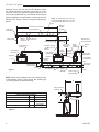
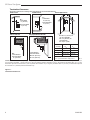
DV Power Vent System
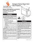
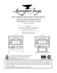
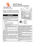
Maximum vent is 110 feet, plus six 90° elbows or twelve
45° elbows. Minimum horizontal vent length is 8 feet,
maximum vertical rise above the fireplace is 66 feet. The
vent can be installed with any combination of rise and run
between appliance and termination, including up to 5 feet
below the unit. Figure 1. Ensure vent pipe is properly supported.
NOTE: All outside pipe joints must be
sealed with flexible aluminum duct tape
or equivalent. DO NOT use vinyl duct
tape.
Building
support
Framing
Horizontal / Inclined Run
Power Vent
Termination
Support Brackets
Elbow
Exterior Wall
Adjustable Pipe
Minimum Vent
Run 8’ Horizontal
Vent Sections
Firestop/ Spacer
Probe Adapter
(required)
Maximum Venting
110’ Max. Up to 6
Elbows
Vent Reducer
(if required)
Vent Reducer
(if Required)
Fireplace
Ceiling
Probe
Vent ReAdapter
ducer (if
(required) required)
Fireplace
Floor
Probe
Adapter
(required)
Maximum
Vertical Rise
66 Feet
Power Vent
Termination
Fireplace
Cut to Length
or Adjustable
Pipe
Power Vent
Termination
Firestop/
Spacer
5 Feet Below
Bottom of Fireplace Maximum
Figure 1
Elbow
Vent Sections
Support
Brackets
NOTE: When using fireplaces with 5 x 8 venting collar,
a vent reducer must be used as the first starting pipe
(7TDVP58) before the probe assembly.
FP2790
Exterior
Wall
Cut to Length or
Adjustable Pipe
FP2790
B
power vent run
Probe Assembly
(required)
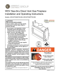
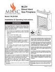
Power Vent Venting Chart
Maximum Number of Elbows
-
Maximum Feet of Run
A + B
Minimum Horizontal Run
B
Minimum Vertical Rise
A
Maximum Vertical Rise
A
6
110 feet
8 feet
Probe Assembly
and Elbows
66 feet
A
Vent Reducer
(if required)
Figure 2
FP2791
FP2791
vent chart
20302353
DV Power Vent System
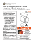
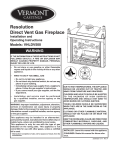
General Venting Information - Termination Location
INSIDE CORNER DETAIL G V H A D L V E C V B F Figure 3 Termination Locations
B Fixed
Closed
Ope
ra
V B B Operable
B V V Fixed
Closed
B J X
X AIR SUPPLY INLET V K X AREA WHERE TERMINAL IS NOT PERMITTED Canadian Installations1
CFM145a DV Termin Location 5/01/01 Rev. 12/05/01 sta M I A CFM145a V VENT TERMINATION V ble
US Installations2
A = Clearance above grade, veranda, porch, 12” (30 cm)
12” (30 cm)
deck, or balcony
B = Clearance to window or door that may be 6” (15 cm) for appliances 6” (15 cm) for appliances
opened
< 10,000BTU/h (3kW), 12” (30 cm) < 10,000 BTU/h (3kW), 9”
for appliances > 10,000 Btuh (3kW) and
(23 cm) for appliances > 10,000
< 100,000 BTU/h (30kW), 36” (91 cm)
Btuh (3kW) and < 50,000 BTU/h
for appliances > 100,000 BTU/h (30kW)
(15kW), 12” (30 cm) for
appliances > 50,000 BTU/h(15kW)
C = Clearance to permanently closed window
12” (305 mm) recommended to
12” (305 mm) recommended to prevent window condensation
prevent window condensation
D = Vertical clearance to ventilated soffit located
above the terminal within a horizontal 18” (458 mm)
18” (458 mm)
distance of 2’ (610mm) from the center
line of the terminal
E = Clearance to unventilated soffit
12” (305 mm)
12” (305 mm)
F = Clearance to outside corner see next page
see next page
G =Clearance to inside corner (see next page) see next page
see next page
H = Clearance to each inside of center line
3’ (91 cm) within a height of 15’ (5 m) 3’ (91 cm) within a height of 15’
extended above meter/regulator assembly
above the meter/regulator assembly
(5 m) above the meter/regulator
assy
I = Clearance to service regulator vent outlet
3’ (91 cm)
3’ (91 cm)
J = Clearance to nonmechanical air supply inlet 6” (15 cm) for appliances < 10,000
6” (15 cm) for appliances
to building or the combustion air inlet to any BTU/h (3kW), 12” (30 cm) for
< 10,000 BTU/h (3kW), 9”
other appliances
appliances > 10,000 BTU/h (3kW) and (23 cm) for appliances > 10,000
< 100,000 Btuh (30kW), 36” (91 cm)
BTU/h (3kW) and < 50,000 BTU/h
for appliances > 100,000 BTU/h (30kW)
(15kW), 12” (30 cm) for appliances > 50,000 BTU/h(15kW)
K = Clearance to a mechanical air supply inlet
6’ (1.83 m)
3’ (91 cm) above if within 10'
(3 m) horizontally
L = Clearance above paved sidewalk or paved 7’ (2.13 m)† 7’ (2.13 m)†
driveway located on public property
M =Clearance under veranda, porch, deck or
12” (30 cm) 12” (30cm)
balcony
1 In accordance with the current CSA-B149 Installation Codes
2 In accordance with the current ANSI Z223.1/NFPA 54 National Fuel
Gas Codes
† A vent shall not terminate directly above a sidewalk or paved
driveway which is located between two single family dwellings and serves both dwellings
only permitted if veranda, porch, deck or balcony is fully open on a
minimum 2 sides beneath the floor:
20302353
NOTE: 1. Local codes or regulations may require different clearances.
2. The special venting system used on Direct Vent Fireplaces are certified as part of the appliance, with clearances tested and approved by the listing agency.
3. MHSC assumes no responsibility for the improper performance of the appliance when the venting system does not meet these requirements.
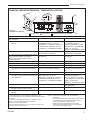
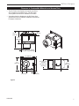
DV Power Vent System
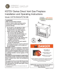
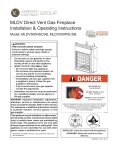
Termination Clearances
Termination clearances for buildings with combustible and noncombustible exteriors.
Alcove Applications*
Inside Corner
Outside Corner
G=
Combustible
6" (152 mm)
G
F=
Combustible
6" (152 mm)
Noncombustible
2" (51 mm)
V
Noncombustible
2" (51 mm)
V
C
V
E
O
F
Balcony with perpendicular side wall
Balcony with no side wall
D
C
E = Min. 6” (152 mm) for
non-vinyl sidewalls
Min. 12” (305 mm) for
vinyl sidewalls
O = 8’ (2.4 m) Min.
M
M
V
V
P
M=
Combustible &
Noncombustible
12" (305 mm)
Combustible &
Noncombustible
M = 24" (610 mm)
P = 20” (508 mm)
No.
of Caps DMin. CMax.
1
3’ (914 mm) 2 x DActual
2
6’ (1.8 m)
1 x DActual
3
9’ (2.7 m)
2/3 x DActual
4
12’ (3.7 m) 1/2 x DActual
DMin. = # of Termination caps x 3
CMax. = (2 / # termination caps) x DActual
584-15
*NOTE: Termination in an alcove space (spaces open only on one side and with an overhang) is permitted with the dimensions specified for vinyl or
non-vinyl siding and soffits. 1. There must be a 3’ (914 mm) minimum between termination caps. 2. All mechanical air intakes within 10’ (1 m) of a
termination cap must be a minimum of 3’ (914 mm) below the termination cap. 3. All gravity air intakes within 3’ (914 mm) of a termination cap must
be a minimum of 1’ (305 mm) below the termination cap.
Figure 4 Termination Clearances
20302353
DV Power Vent System
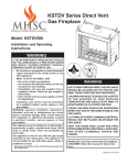
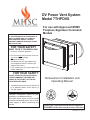
Clearance to Combustible Materials and Access Door
• The DV Power Vent System box needs a minimum
•
3/8” clearance all around the box. The DV Power
Vent System box has a 3/8” standoff on all sides.
Vent pipes from the fireplace to the DV Power Vent
System must refer to fireplace installation instructions
for proper clearances.
46QE”
(106 mm)
1656QE”
(430 mm)
1156O”
(292 mm)
1356O” (343 mm) (Actual)
14” (356 mm) (Framing
16” (406 mm)
956O” (241 mm) (Actual)
10” (254 mm) (Framing)
12”
(305 mm)
46QE”
(116 mm)
856QE”
(224 mm)
156O”
(38 mm)
Figure 5
FP2791
power vent framing clearances
20302353
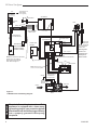
DV Power Vent System
120V Supply 60 Hz
(Field supplied
14-2 w/ ground)
Black
White
Green
To
Junction Box
AC Module
Junction
Box
{
Aux.
Plug in
Connector
Optional
Blower
Pilot
White
Light { Black
White
Black
Black
White
Green
Connector Pin
To Control Board
Field Supplied
14-2 w/ Ground
RF Receiver
ON/OFF Button
Control Board
*Rear Burner
Solenoid Valve
(KHLDV, KSTDV,
VCPDV, VHLDV)
Power Vent
Module
Conversion
NG/LP
Ignitor / Sparker
Plug-in Connector
Control Board to Command Center
Black
Power Vent
*NOTE: For rear burner shut-down
models, aux. wire must be
disconnected from solenoid
valve. Refer to Page 10
Disconnect
Themopile
NOTE: Thermopile
is not used with
Power Vent
Black
Red
Sensor
Yellow
Black
White
Green
Input 300 Watt
Max. Each
Standing Pilot
mode is not
available when
thermopile is
disconnected.
Red
Red
Vacuum Switch
OFF/LO
LED
ON/HI
Master Switch
NOTE: Wall switch wires
must be connected together
Ground
Plug-in Connector
Stepper Motor to
Control Board
Command Center
DC Power/Green
Plug-in Connector
Control Board to
Solenoid
Gas Out
Gas In
Figure 6 7THPDVS Power Vent Wiring Diagram
Pilot Gas Tubing
Valve
WARNING
FP2793
pv wiring diagram
Electrical Grounding Instructions: This
appliance is equipped with a three-prong
(grounding) plug for your protection against
shock hazard and should be plugged directly
into a properly grounded three-prong
receptacle.
20302353
DV Power Vent System
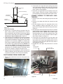
POWER VENT TERMINATION
INSTALLATION
1. Locate and cut the vent opening in the wall. Combustible and noncombustible walls: Cut a 10” H x 14” W
(254 x 356 mm) vent opening through the exterior wall
and frame as shown in Figure 7.
2. Secure the firestop to the inside frame and center in
the 10” H x 14” W vent opening.
3. Install the power vent in the opening through the exterior wall until the mounting flange is flush against the
wall.
4. Attach the power vent with screws provided and seal
top and sides of the mounting flange with caulking.
856O”
(216 mm)
Maximum Combustible Wall
Siding
Interior
Finish Wall
Sheathing
Firestop
Caulking
Figure 8 All Three (3) Discs Fully Open
FP2830
disc #3
14”
(356 mm)
10”
Power
(254 mm)
Vent
Twist lock
Adjustable
Termination
Pipe
Siding “J”
Channel
Figure 7
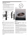
RESTRICTOR DISCFP2820
INSTALLATION AND SET
wall framing
UP
Before starting vent assembly, the restrictor discs must
be installed. NOTE: Installation is easiest from the top of
the fireplace.
1. Check the inside vent pipe size; either 4” or 5”. Use
the correct size restrictors provided for the correct vent
size.
2. Stacking all three (3) restrictor discs, screw together
with one stainless steel screw in center. Adjust so that
all three discs are stacked fully open as shown in Figure 8.
NOTE: To achieve the proper flame appearance and ignition, the restrictor disc setting may need to be adjusted
by closing any two (2) of the discs depending on each
individual installation requirements. Figure 9. However,
most installations do not require any adjustment to the
fully open disc setting when outer vent pipe installation is
properly sealed with aluminum tape. Refer to Page 4 and
next section.
20302353
Figure 9 Restrictor disc
(shown with 2 discs closed)
FP2822PROBE VENT ASSEMBLY AND
INSTALL
restrictor
plate
VENTING
PIPE
1. Attach the probe assembly to the fireplace collar:
Fireplace collars 4 x 7 venting: The probe assembly will slide on collar. Attach with two (2) sheet metal
screws. Make sure the probe stem is facing toward the
side of the fireplace where the vacuum hose will be
inserted. Figure 10
Fireplace collars 5 x 8 venting: You must use a 5 x
8 to 4 x 7 reducer (7TDVP58). Install the reducer by
pushing down into the fireplace collar and attach with
two (2) sheet metal screws. Push the probe assembly
down onto reducer and attach with two (2) sheet metal
screws. Make sure the probe stem is facing toward the
side of the fireplace where the vacuum hose will be
inserted. Figure 10
2. Install the vacuum hose to the probe stem by pushing
the hose onto the stem 1/4”. Figure 10
DV Power Vent System
Twist lock Pipe
Section
Probe Vent Assembly
Vacuum Hose
Vent Reducer
(if required)
Fireplace
Starting Collar
FP2821
Figure 10 Probe Vent Assembly
3. Remove the 1” knockout hole on the side of the fireplace. Snap in plastic
ring provided and run vacuum
FP2821
hose through holeprobe
and into
lower
vent
assyaccess area making
sure to secure hose away from fireplace top. DO NOT
allow hose to lay on fireplace top. Figure 16
4. Vent sections may be added to the previously installed
probe assembly in accordance with the requirements
of the fireplace installation manual and the vent charts
provided in this instruction. NOTE: All outside pipe
joints must be sealed with flexible aluminum duct tape
or equivalent. Due to high temperatures, DO NOT use
vinyl duct tape. NOTE: The last pipe before the power
vent must be an adjustable termination section provided with kit or 20” termination pipe (7TDVP20/8), which
can be cut to length, to attach to the power vent.
5. When the power vent installation is to be serviced from
inside the dwelling, the slip pipe section must be used
to attach to the power vent for future serviceability.
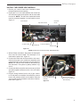
2. Connect the 14-2 w/ground romex wiring (not provided) to the power vent black, white and green wires with
wire nuts provided. Reinstall cover and tighten strain
relief. Figure 6 wiring diagram
3. Route the 14-2 w/ground wire from power vent to fireplace location. Ensure the wiring is safely placed to
prevent damage by framing nails and drywall screws.
CONNECT WIRING TO FIREPLACE JUNCTION BOX
1. Remove screw from side holding the junction box and
lift out.
2. Remove cover plate and outlet from junction box and
discard.
3. Run the fireplace power 14-2 w/ground (refer to fireplace installation manual) and power vent 14-2 w/
ground wire through strain relief and into junction box.
Figure 16
4. Run the black, white and green wires from A/C module
labeled AUX through the strain relief of the new cover
plate provided in the kit. NOTE: Some models require
disconnecting the aux. wire from solenoid valve. (This
will make the rear burner shut-down feature inoperable. Refer to Figure 6.) Figure 12
5. Connect the 14-2 w/ground wire from the power vent
to the AUX wires from the A/C module with wire nuts.
Also at this time, connect the fireplace power 14-2 w/
ground wire to the outlet wires with wire nuts. Refer to
wiring diagram Figure 6.
6. Reinstall the cover plate and junction box in reverse
order.
AUX Wire from
A/C Module
Junction Box
New Cover Plate
ROUTE WIRING FROM POWER VENT
1. Remove the junction box cover from the power vent.
Figure 11
FP2824
FP2823
Figure 11
10
14-2 w/Ground (Field Supplied)
FP2823
14-2 w ground
Power Vent Module
Figure 12
Vacuum Hose
20302353
FP2824
AUX wires
DV Power Vent System
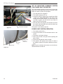
INSTALL THE POWER VENT MODULE
1. Remove the control board and Command Center
through fireplace access opening.
2. Unplug the 2 ft.-6 wire cable between the control box
and command center and replace with the new cable
from the kit. NOTE: The red wires marked wall switch
must be connected together if no wall switch is used.
Figure 13
Control Board
Command
Center
6-pin Wire Harness
FP2825
2 ft. Wire Cable
A/C Module
Power Vent Module
Vacuum Hose
Figure 13
NOTE: Firebox face removed for clarity. (WDV600 shown)
3. With a Phillips screwdriver, disconnect the thermopile
wires from the control board. The thermopile is not
used with the power vent. Figure 14
4. Connect the black and red wires with the fork terminals from the power vent module wire assembly to the
control board where the thermopile was disconnected.
NOTE: The red wire must connect to the positive (+)
red connection. The system is polarity sensitive. Figure 14
5. Connect the black and yellow wires to the two (2) black
and yellow spade connectors on the 2 ft.-6 wire cable.
Figure 14
6. Plug the wiring harness into the six (6) pin connector on the power vent module. Also attach the vacuum
hose to the pressure switch on the module. Place the
velcro on the module and attach to the floor of the fireplace area. Figure 13
20302353
FP2825
power vent module
FP2828
Red & Black Wires from
Power Vent Module Wire
Assembly
Figure 14
Black & Yellow Wires
from Power Vent Module
Wire Assembly
FP2828
power module wire assy
11
DV Power Vent System
SET UP SIGNATURE COMMAND SYSTEM
FOR POWER VENT OPERATION
The control board program must be reset to operate the
power vent. Follow these instructions to reset the control
board from basic to power vent operation.
FP2826
Disconnect Thermopile
Figure 15
1. Turn ON power to the fireplace.
2. Turn master switch to OFF (o).
3. Locate the on/off RF button on the control board. With
a paper clip, press and hold the RF button while
turning ON the master switch. You should hear one
(1) beep for power vent ON and two (2) beeps for
power vent OFF and release.
4. After the power vent program is turned ON, turn OFF
the master switch and place the control box back into
the control access area.
The system is now ready to operate.
POWER VENT SYSTEM OPERATION
FP2826
thermopile
FP2827
Figure 16
12
Vacuum
Hose
Power Supply
IN and to
Power Vent
Plastic Ring
1. Turn master switch ON (-).
2. Press the ON button at the command center or the
remote.
3. The power vent blower will start.
4. After a few seconds, the igniter starts sparking and
pilot will light.
5. The burner will light after a few seconds.
6. The fireplace will operate until turned off. Refer to
the fireplace manual for fireplace operational instructions.
NOTE: Power vent blower will continue to run for 90 seconds after flame is turned off.
FP2827
power supply cord
20302353
DV Power Vent System
9
21
8
6
22
5
10
11
7
12
13
15
14
4
3
23
2
1
16
17
20
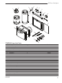
7THPDVS Power Vent Parts
Ref.
1.
2.
3.
4.
5.
6.
7.
8.
9.
10.
11.
12.
13.
14.
15.
16.
17.
18.
19.
20.
21.
22.
23.
Description
19
Qty.
Termination Assy.
1
Firestop Assy.
1
Probe Assy.
1
Adjustable Termination Pipe
1
2353
4” Restrictor
3
power vent parts
5” Restrictor
3
SS Screw
1
Strain Relief
1
Electrical Cover
1
#8 Screw
2
Wire Nuts
6
Velcro
1
Module, Power Vent SCS
1
Cable, CC/CB 24” w/power leads SCS
1
Wire, Power Vent Module SCS
1
7 ft. Rubber Tubing
1
Wire Ties
2
Receptacle
2
Electrical Cover Plate
1
Strain Relief Connector
1
Termination Bolt Bag
1
Pipe Bolt Bag
1
Installation Manual 1
20302353
18
Part No.
3
4
20300939
20302228
20302272
69D3068
45D0551
56D3027
20014369
26D0215
20301694
0052825B
20302355
37D0394
20301934
20301889
20302293
20302239
17D0601
7522253
20302235
10000821
20002404
0056167
20302353
13
DV Power Vent System
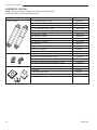
HORIZONTAL VENTING
NOTE: The Power Vent Kit (7THPDVS) is designed and listed for use
with MHSC Twist lock Direct Vent Systems only.
Description
Model Number
Twist lock Pipe
20" Termination Pipe - 8 pack
7TDVP20/8
10" - 16" Adjustable Termination Pipe - 4 pack
7TDVPA/4
12" - 18" Adjustable Vent Length 7TDVP1218
35" - 64" Adjustable Vent Length
7TDVP3564
8" Vent Pipe - 4 pack
7TDVP8/4
12" Vent Pipe - 4 pack
7TDVP12/4
24" Vent Pipe - 4 pack
7TDVP24/4
36" Vent Pipe
7TDVP36
36" Vent Pipe - 30 pack
7TDVP36/30
48" Vent Pipe
7TDVP48
48" Vent Pipe - 30 pack
7TDVP48/30
5 x 8 to 4 x 7 Reducer
7TDVP58
584E
Twist
lock Elbows
45° Elbow for Vertical/Horizontal Offset
7TDVP45
45° Elbow for Vertical Offsets - 8 pack
7TDVP45/8
90° Elbow for Vertical/Horizontal Offset
7TDVP90
90° Elbow for Vertical/Horizontal Offset - 8 pack
7TDVP90/8
Shields and Supports
1" Firestop
7DV1FS
3" Firestop
7DV3FS
1" Attic Insulation Shield
7DV1AIS
Combination Horizontal Offset/Roof Support
7DVCS
Venting Components
Telescope vent
2/25/99 djt
10/20/99 twist lock
3/10/10 T-lock
584m
twist lock elbows
584H
Venting components
584G
584I
attic insulation shield
vent components
Venting Components
2/25/99 djt
offset
support
Firestop spacer
2/25/99 djt
2/25/99 djt
14
20302353
DV Power Vent System
20302353
15
DV Power Vent System
MHSC
149 Cleveland Drive • Paris, Kentucky 40361
www.mhsc.com
16
20302353