1
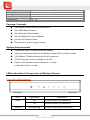
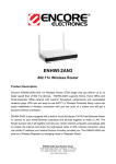
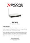
© 2010 Encore Electronics, Inc. All rights reserved.COVER © 2010 Encore Electronics, Inc. Product specifications, size, and shape are subject to change without notice, and actual product appearance may differ from that depicted herein. All trademarks and brand names are the properties of their respective holders. TABLE OF CONTENTS REVISION HISTORY .............................................................................................. 4 INTRODUCTION ................................................................................................... 5 FEATURES .............................................................................................................. 5 SPECIFICATIONS ..................................................................................................... 6 PACKAGE CONTENTS ............................................................................................. 7 SYSTEM REQUIREMENTS........................................................................................ 7 LEDS INDICATION & CONNECTORS OF WIRELESS ROUTER ................................... 7 INSTALLATION INSTRUCTION ................................................................................. 8 PC NETWORK TCP/IP SETTING ....................................................................... 9 WINDOWS 95/98/ME ............................................................................................. 9 WINDOWS 2000 ..................................................................................................... 9 WINDOWS XP / VISTA / 7 ..................................................................................... 10 CONFIGURATION ............................................................................................... 11 LOGIN TO THE WLAN ROUTER THROUGH WIRELESS LAN ................................. 12 LOGIN TO THE WLAN ROUTER............................................................................ 12 USING THE WEB BROWSER .................................................................................. 12 SETUP WIZARD .................................................................................................... 12 ADVANCED CONFIGURATION ................................................................................ 22 WAN ................................................................................................................... 22 Connection Type ............................................................................................. 22 Dynamic DNS ................................................................................................. 28 WIRELESS ............................................................................................................ 29 Basic ............................................................................................................... 29 Security........................................................................................................... 30 Advanced ........................................................................................................ 33 Wi-Fi Protected Setup .................................................................................... 34 LAN .................................................................................................................... 35 1 www.encore-usa.com Basic ............................................................................................................... 35 DHCP ............................................................................................................. 35 ROUTING.............................................................................................................. 36 Static ............................................................................................................... 36 Dynamic ......................................................................................................... 37 Routing Table ................................................................................................. 37 ACCESS CONTROL ............................................................................................... 38 Filters ............................................................................................................. 38 Virtual Server ................................................................................................. 44 Special AP ...................................................................................................... 45 DMZ ............................................................................................................... 46 Firewall Rule .................................................................................................. 47 SYSTEM ............................................................................................................... 49 Password ........................................................................................................ 49 Time ................................................................................................................ 50 Device Information......................................................................................... 51 Log ................................................................................................................. 52 Log Setting ..................................................................................................... 53 Statistic ........................................................................................................... 54 Restart ............................................................................................................ 55 Firmware ........................................................................................................ 56 Configuration ................................................................................................. 57 UPnP .............................................................................................................. 58 Ping Test ......................................................................................................... 59 Remote Management ...................................................................................... 60 SETTING THE ENHWI-1AN4 AS AN ACCESS POINT. ............................................ 61 Product specifications, size, and shape are subject to change without notice, and actual product appearance may differ from that depicted herein. All trademarks and brand names are the properties of their respective holders. © 2010 Encore Electronics, Inc. All rights reserved. 2 www.encore-usa.com FCC Warning This equipment has been tested and found to comply with the limits for a Class C digital device, pursuant to part 15 of the FCC Rules. These limits are designed to provide reasonable protection against harmful interference in a residential installation. This equipment generates, uses, and can radiate radio frequency energy and, if not installed and used in accordance with the instructions, may cause harmful interference to radio communication. However, there is no guarantee that interference will not occur in a particular installation. If this equipment does cause harmful interference to radio or television reception, which can be determined by turning the equipment off and on, the user is encouraged to try to correct the interference by one or more of the following measures: - Reorient or relocate the receiving antenna. - Increase the separation between the equipment and receiver. - Connect the equipment into an outlet on a circuit different from that to which the receiver is connected. - Consult the dealer or an experienced radio/TV technician for help. FCC Caution: Any changes or modifications not expressly approved by the party responsible for compliance could void the user’s authority to operate this equipment. This device complies with Part 15 of the FCC Rules. Operation is subject to the following two conditions: (1) This device may not cause harmful interference, and (2) this device must accept any interference received, including interference that may cause undesired operation. IMPORTANT NOTE: FCC Radiation Exposure Statement: This equipment complies with FCC radiation exposure limits set forth for an uncontrolled environment. This equipment should be installed and operated with a minimum distance of about eight inches (20cm) between the radiator and your body. This transmitter must not be co-located or operated in conjunction with any other antenna or transmitter. IEEE802.11b or 802.11g operation of this product in the USA is firmware-limited to channels 1 through 11. 3 www.encore-usa.com Notice: Changes or modifications to the equipment, which are not approved by the party responsible for compliance, could affect the user's authority to operate the equipment. Company has an on-going policy of upgrading its products and it may be possible that information in this document is not up-to-date. Please check with your local distributors for the latest information. Revision History Revision History V1.0 1st release 4 www.encore-usa.com Introduction The ENHWI-1AN4 Wireless N150 Router complies with IEEE 802.11n, and provides faster and farther range than 802.11g while being backward compatible with 802.11g and 802.11b mode. This router uses advanced broadband router chipset and wireless LAN chipset solution to let you enjoy high-speed Wired and Wireless connection. Simply connect this device to a Cable or DSL modem and then you can share your high-speed Internet access with multiple PCs at your home with or without wires. It creates a secure Wired and Wireless network for you to share photos, files, video, music, printer and network storage. ENHWI-1AN4 provides maximum transfer rate up to 150Mbps and supports WEP, WPA, WPA2, 802.1x high-level WLAN security features that guarantee the best security for users. Features Up to 150 Mbps data transfer rates Backward compatible with IEEE 802.11b/g Built-in 4 port 10/100 Ethernet switch with auto speed sensing Supports Access Point Supports NAT, DHCP Server/Client Supports VPN pass through - IPSec, PPTP, L2TP Supports Virtual Server / Port Trigger Supports Virtual DMZ Host, DDNS, UPnP Supports 64/128-bit WEP, WPA, WPA2, 802.1x Authentication Encryption Supports WPS software PBC/PIN Supports MAC Filter, IP Filter, URL/Domain Blocking, Protocol Filter Supports Auto-crossover (MDI/MDI-X) function Supports software upgrade through Web Friendly web-based GUI Configuration and Management 5 www.encore-usa.com Specifications Data Transfer Rates Standard 150Mbps (802.11n mode) 54Mbps (802.11g mode) 11Mbps (802.11b mode) IEEE 802.11b / 802.11g / 802.11n (Wireless) IEEE 802.3, IEEE 802.3u, IEEE 802.3x Full Duplex Flow Control (Wired) Operating Radius 100m Indoor, 300m Outdoor Internet Access Connect to Broadband (Cable or xDSL) modem or Ethernet backbone for Internet Surfing WAN Connection Dynamic IP, Static IP, PPPoE, PPTP, L2TP IP Management Security Firewall Management Interface LED Indicators Antenna Wireless Frequency Output Power Receiver Sensitivity Transmit Output Power Power Dimensions (approx.) Net Weight (approx.) NAT (Network Address Translation) DHCP (Dynamic Host Configuration Protocol) Server/Client Support VPN pass through – IPSec, PPTP, L2TP Support Virtual server / Port Trigger Support Virtual DMZ host Support Dynamic DNS Support UPnP (Internet Gateway Device) Support 64/128-bit WEP Data Encryption Support WPA, WPA2 (802.11i) security Support WPS software PBC/PIN Support MAC ACL (MAC Access Control List) Support PAP / CHAP / MS-CHAP / MS-CHAPv2 authentication Support 802.1x RADIUS Server Support MAC filter Support IP filter Support URL/Domain Blocking Support Protocol Filter Web-based GUI Configuration / Management Web Remote Login from WAN Software Upgrade through Web Support NTP update Support System Log Support Configuration setting Backup/Restore/Reset to Default LAN x 4, WAN x 1 POWER, STATUS, LAN x 4, WAN x 1, WLAN x 1 One 2dBi Dipole Antenna 2.4000~2.4835GHz 15 dBm IEEE 802.11b : -88 dBm (Typical), IEEE 802.11g : -70dBm (Typical) IEEE 802.11n: 20Mhz -68dBm ; 40Mhz -65dBm (Typical) 11b : 18±1 dBm, 11g : 15±1 dBm , 11n : 15±1 dBm DC 9V 0.5A 14.5 x 9.6 x 2.6 cm (W x L x H) 152.1 g 6 www.encore-usa.com Operating Temperature Humidity Storage Temperature Supported OS Regulations 0°C ~ 40°C 5 % ~ 95 % (non-condensing) 0°C ~ 70°C Windows 98SE, ME, 2000, XP, Vista, Win7, Mac and Linux FCC, CE Package Contents One ENHWI-1AN4 Wireless N150 Router One 2dBi Dipole Antenna One External Power Adapter One CD-ROM with User’s Manual One RJ-45 Ethernet Cable One type-A to type-C plug converter System Requirements Computers with an installed Ethernet adapter. Valid Internet Access account and Ethernet based DSL or Cable modem. 10/100Base-T Ethernet cable with RJ-45 connector. TCP/IP protocol must be installed on all PCs. System with Windows Internet Explorer 7 or later, or Mozilla Firefox 3 or later. LEDs Indication & Connectors of Wireless Router Front Panel LEDs Indication LED Light Status PWR On Wireless Router is powered on. Off Wireless Router is powered off. WLAN Slow Blinking Description WLAN is successfully connected. 7 www.encore-usa.com Blinking WAN On Data is being sent or received. WAN port is successfully connected Blinking LAN On (1, 2, 3, 4) Blinking Data is being sent or received. LAN port is successfully connected. Data is being sent or received. Back Panel Connectors Button/Port Description Reset Reset configurations to default. You would use the reset button only when a program error has caused your Wireless AP router to hang. Press the button and hold after 6 seconds. LAN Ethernet RJ-45 connector, connect to PC with a RJ-45 Ethernet cable. (1x, 2x, 3x, 4x) WAN Ethernet RJ-45 connector, connect to WAN access device, such as the Cable modem or ADSL modem. DC-9V Power connector, connect to the power adapter (DC-9V) packaged with the AP router. Installation Instruction 1) 2) 3) 4) 5) Power off the DSL or Cable modem. Connect computer to the LAN port on the ENHWI-1AN4 Router with Ethernet cable. Connect the DSL or Cable modem to the WAN port on the ENHWI-1AN4 Router with Ethernet cable. Power on the DSL or Cable modem first, and then connect power adapter to the power jack on the rear panel of ENHWI-1AN4 Router and plug the power cable into an outlet. Check LEDs. 8 www.encore-usa.com a) b) c) Once power on the ENHWI-1AN4 Router, Power LED should be on. LAN LED should be on for each active LAN connection. The WAN LED should be on when the DSL or Cable modem is connected. PC Network TCP/IP Setting The network TCP/IP settings differ based on the computer’s operating system (Win95/98/ME/NT/2000/XP/Vista) and are as follows. Windows 95/98/ME 1. Click on the “Network neighborhood” icon found on the desktop. 2. Click the right mouse button and a context menu will be show. 3. Select “Properties” to enter the TCP/IP setting screen. 4. Select “Obtain an IP address automatically” on the “IP address” field. Windows 2000 Double click on the “My Computer” icon on the desktop. When “My Computer” window opens, selects “Control Panel” and then opens the “Network dialup connection” applet. 9 www.encore-usa.com Double click on the “Local area network connection” icon. Select “Properties” to enter the TCP/IP setting window. 1. In the “Local area network status” window, click on “Properties.” 2. In the “Local area network connection” window, first select TCP/IP setting and then select “Properties.” 3. Set both “IP address” and “DNS” to Automatic configuration. Windows XP / Vista / 7 Point the cursor and click the right button on the “My Network Place” icon. Select “properties” to enter the TCP/IP setting window. 10 www.encore-usa.com 1. Set “IP address” to “Obtain an IP address automatically.” 2. Set “DNS” to “Obtain DNS server address automatically.” Configuration First make sure that the network connections are functioning normally. This WLAN Router can be configured using web browser. 11 www.encore-usa.com Login to the WLAN Router through Wireless LAN Before configuring the WLAN Router through WLAN, make sure that the SSID, Channel and the Security is set properly. The default setting of the WLAN Router that you will use: SSID: default Channel: 11 802.11 Mode: 802.11b/g/n mixed mode Channel bandwidth: 20/40MHz Security: Disable Login to the WLAN Router Before you configure this device, note that when the WLAN Router, make sure the host PC must be set on the IP subnet that can be accessed by the xDSL/Cable modem. For example, when the default network address of the xDSL/Cable modem Ethernet interface is 192.168.10.x, then the host PC should be set at 192.168.10.xxx (where xxx is a number between 2 and 254), and the default subnet mask is 255.255.255.0. Using the Web Browser 1. Open the Internet browser. 2. Enter IP address http://192.168.10.1 (the factory-default IP address setting) to the URL web address location. 3. When the following dialog box appears, enter the user name and password to login to the main configuration window, the default username and password is “admin”. Setup Wizard Setup wizard is provided as part of the web configuration utility. User can simply follow the step-by-step process to get the wireless Router configuration ready to run in 6 easy steps by clicking on the “Wizard” button on the function menu. The following screen will appear. 12 www.encore-usa.com Please click “Next” to continue. Step 1: Set your new password Setting the new admin password of the WLAN Router. Please click “Next” to continue. Step 2: Choose time zone Select the time zone from the drop down list. Please click “Next” to continue. 13 www.encore-usa.com Step 3: Set LAN connection and DHCP server Set user’s IP address and mask. The default IP is 192.168.10.1. If the user chooses to enable DHCP, please click “Enable”. DHCP enabled is able to automatically assign IP addresses. Please assign the range of IP addresses in the fields of “Range start” and “Range end”. Please click “Next” to continue. Step 4: Set Internet connection The WLAN Router will attempt to auto detect your Internet Connection. 14 www.encore-usa.com Obtain IP automatically (DHCP client): If the user has enabled DHCP server, choose "Obtain IP automatically (DHCP client)" to have the WLAN Router assign IP addresses automatically. Fixed IP Address: 15 www.encore-usa.com If the Internet Service Provider (ISP) assigns a fixed IP address, choose this option and enter the assigned WAN IP Address, WAN Subnet Mask, WAN Gateway Address and DNS Server Addresses for the WLAN Router. PPPoE to obtain IP automatically: 16 www.encore-usa.com If connected to the Internet using a PPPoE (Dial-up xDSL) connection, and the ISP provides a User Name and Password, then choose this option and enter the required information. PPPoE with a fixed IP address: If connected to the Internet using a PPPoE (Dial-up xDSL) connection and the ISP 17 www.encore-usa.com provides a User Name, Password and a Fixed IP Address, choose this option and enter the required information. PPTP: If connected to the Internet using a PPTP xDSL connection, enter your IP, Subnet Mask, Gateway, Server IP, PPTP Account and PPTP Password. L2TP: 18 www.encore-usa.com If connected to the Internet using a L2TP (Dial-up xDSL) connection and the ISP provide a Server IP, Account and Password information, choose this option and enter the required information. 19 www.encore-usa.com BigPond Cable (Australia): If your ISP is BigPond Cable, the ISP will provide a User Name, Password, Authentication Server and Login Server IP (Optional). Choose this option and enter the required information. 20 www.encore-usa.com Step 5: Set Wireless LAN connection Click “Enable” to enable Wireless LAN. If user enables the Wireless LAN, type the SSID in the text box and select a communications channel. The SSID and channel must be the same as wireless devices attempting to connect to the WLAN Router. Step 6: Setup completed The Setup wizard is now completed. The new settings will be effective after the WLAN Router restarts. Please click “Restart” to reboot the WLAN Router. If user does not want to make any changes, please click “Exit” to quit without any changes. User also can go back to modify the setting by clicking “Back”. 21 www.encore-usa.com Advanced configuration WAN This screen enables users to set up the WLAN Router WAN connection, specify the IP address for the WAN, add DNS numbers, and enter the MAC address. Connection Type Select the connection type, either DHCP client, Fixed IP, PPPoE, PPTP, L2TP or BigPond Cable from the drop-down list. DHCP Client or Fixed IP If user has enabled DHCP server, choose "Obtain IP automatically (DHCP client)" to have the router assign IP addresses automatically. 22 www.encore-usa.com WAN IP Address: Select whether user wants to specify an IP address manually, or want DHCP to obtain an IP address automatically. When Specify IP is selected, type the IP address, subnet mask, and default gateway in the text boxes. User’s ISP will provide with this information. IP Address: For the Specify mode, enter the specific IP address that provided by your ISP. Subnet Mask: For the Specify mode, enter the specific subnet mask that provided by your ISP. Gateway: For the Specify mode, enter the specific gateway IP address that provided by your ISP. DNS 1/2: Manually specific DNS server IP address; For the Obtain IP Automatically mode, if enter 0.0.0.0 in this filed, the DHCP server will provides DNS server automatically. Clone MAC Address: If your ISP requires you to enter a specific MAC address, please enter it in. The Clone MAC Address button is used to copy the MAC address of your Ethernet adapter to the Router. 23 www.encore-usa.com PPPoE If connected to the Internet using a PPPoE (Dial-up xDSL) Modem, the ISP will provide a Password and User Name, and then the ISP uses PPPoE. Choose this option and enter the required information. WAN IP: Select the WAN IP address Obtain from ISP automatically or enter the specified IP address. Server Name: Enter the server name provided by ISP (optional). User Name: Enter the user name provided by ISP. Password: Enter the password provided by ISP. Retype Password: Enter the password again. DNS: Enter the IP address of specified DNS server here, default value 0.0.0.0 is get the DNS settings from ISP. Auto-reconnect: Select the connection type for Always-on, Manual or Connect-on Demand connecting. Idle Time Out: Enter the idle time out for Connect on Daemon, when no Internet access during the idle time, the PPPoE connection will auto disconnect. MTU: Enter the specified MTU (Maximum Transmission Unit). The default value is 1492 bytes. 24 www.encore-usa.com PPTP/L2TP with Dynamic IP If connected to the Internet using a PPTP/L2TP (Dial-up xDSL) with dynamic IP connection, enter the your Server IP, PPTP/L2TP Account and PPTP/L2TP Password, if your ISP has provided you with a DNS IP address, enter it in the DNS field, otherwise, leave it zero. 25 www.encore-usa.com PPTP/L2TP with Static IP If connected to the Internet using a PPTP/L2TP (Dial-up xDSL) with static IP connection, enter the your IP Address, Subnet Mask, Gateway IP address, DNS IP address, Server IP address, PPTP Account and PPTP Password. 26 www.encore-usa.com BigPond Cable If your ISP is Big Pond Cable, the ISP will provide a User Name, Password, Authentication Server and Login Server IP (Optional). Choose this option and enter the required information. 27 www.encore-usa.com Dynamic DNS This synchronizes the DDNS server with your current Public IP address when you are online. First, you need to register your preferred DNS with the DDNS provider. Then, please select the DDNS address in the Server Address and fill the related information in the below fields: Host Name, User Name and Password. 28 www.encore-usa.com Wireless This section enables users to configuration the wireless communications parameters for the WLAN Router. Basic This page allow user to enable and disable the wireless LAN function, create a SSID, and select the channel for wireless communications. Enable/Disable: Enables or disables wireless LAN. SSID: Type an SSID in the text box. The SSID of any wireless device must match the SSID typed here in order for the wireless device to access the LAN and WAN via the WLAN Router. SSID Broadcast: While SSID Broadcast is enabled, all wireless clients will be able to view the WLAN Router’s SSID. Channel: Select a transmission channel for wireless communications. The channel of any wireless device must match the channel selected here in order for the wireless device to access the LAN and WAN via the WLAN Router. 29 www.encore-usa.com Security Authentication Type: The authentication type default is set to open system. There are four options: WEP, WPA, WPA2 and WPA2-Auto. WEP: Open System and Shared Key requires the user to set a WEP key to exchange data with other wireless clients that have the same WEP key. 30 www.encore-usa.com WEP Key Format: Select the ASCII or HEX WEP Key Length: Select the WLAN Router supports, 64 and 128-bit encryption. Key Length Hex ASCII Type characters 0-9, A-F, a-f alphanumeric format 64-bit 10 characters 5 characters 128-bit 26 characters 13 characters Key 1: Enables users to create WEP keys with WPS enabled. Manually enter a set of values for Key 1. Note: Key 1 ~ Key 4: Enables users to create up to 4 different WEP keys with WPS disabled. Manually enter a set of values for each key. Select a key to use by clicking the radio button next to the key. WPA/WPA2/WPA-Auto Security with EAP If WPA, WPA2 or WPA2-Auto EAP is selected, the above screen is shown. Please set the length of the encryption key and the parameters for the RADIUS server. Encryption Type: Select the encryption type for TKIP, AES or AUTO encryption. Note: TKIP is available for B or G WLAN Band only. The WLAN Band setting is under Wireless/Advanced. 31 www.encore-usa.com RADIUS Server 1: Enter the IP address, Port used and Shared Secret by the Radius Server 1. WPA/WPA2/WPA2-Auto Security with PSK If WPA, WPA2 or WPA2-Auto PSK is selected, the above screen is shown. Encryption Type: Select the encryption type for TKIP, AES or AUTO encryption. Note: TKIP is available for B or G WLAN Band only. The WLAN Band setting is under Wireless/Advanced. Passphrase: The length should be 8 characters at least. 32 www.encore-usa.com Advanced This screen enables users to configure advanced wireless functions. Beacon Interval: Type the beacon interval in the text box. User can specify a value from 25 to 1000. The default beacon interval is 100. RTS Threshold: Type the RTS (Request-To-Send) threshold in the text box. This value stabilizes data flow. If data flow is irregular, choose values between 256 and 2346 until data flow is normalized. Fragmentation Threshold: Type the fragmentation threshold in the text box. If packet transfer error rates are high, choose values between 1500 and 2346 until packet transfer rates are minimized. (NOTE: set this fragmentation threshold value may diminish system performance.) DTIM Interval: Type a DTIM (Delivery Traffic Indication Message) interval in the text box. User can specify 33 www.encore-usa.com Wi-Fi Protected Setup This screen enables users to configure the Wi-Fi Protected Setup function. WPS: Enable or Disable the WPS (Wi-Fi Protected Setup) function Status: Display the status (Un-configured State/Configured State) information of WPS. Self-PIN Number: Display the current PIN number of the WLAN Router. Client PIN Number: Type Client’s PIN number the client uses to negotiate with the WLAN Router via WPS connection. It is only used when users want their station to join Router's network. Push Button Configuration: Clicking the Start PBC button will invoke the Push Button Configuration (PBC) method of WPS. Push the WPS button on the client side when users want their station to join Router’s network. 34 www.encore-usa.com LAN This page allows the user to configure LAN and DHCP properties, such as the host name, IP address, and subnet mask. Basic Host Name: Type the host name in the text box. The host name is required by some ISPs. The default host name is "Encore". IP Address: This is the IP address of the WLAN Router. The default IP address is 192.168.10.1. Subnet Mask: Type the subnet mask for the WLAN Router in the text box. The default subnet mask is 255.255.255.0. DHCP Enable the DHCP server to allow the WLAN Router to automatically assign IP addresses to devices connecting to the LAN. DHCP is enabled by default. All DHCP client computers are listed in the table at the bottom of the screen, providing the host name, IP address, and MAC address of the client. Start IP: Type an IP address to serve as the start of the IP range that DHCP will use to assign IP addresses to all LAN devices connected to the WLAN Router. 35 www.encore-usa.com End IP: Type an IP address to serve as the end of the IP range that DHCP will use to assign IP addresses to all LAN devices connected to the WLAN Router. Lease Time: The lease time specifies the amount of connection time a network user be allowed with their current dynamic IP address. Routing This page allows the user to setup Static or Dynamic routing Static Network Address: Enter the target IP address in the textbox. Network Mask: Enter the subnet mask in the textbox. Gateway Address: Enter the gateway IP address in the textbox. Interface: Select “LAN” or “WAN” from drop-down list. Metric: Enter the number of ‘hops’ in the textbox; normally you can set the value to ‘0’. Click the “Add” button to save the settings. 36 www.encore-usa.com Dynamic Dynamic routing is a technique developed to automatically adjust routing tables in the event of network failures. The most common dynamic routing protocols is RIP (Routing Information Protocol), which is very common on small networks. Routing Table This page provides a routing table. 37 www.encore-usa.com Access Control This page enables you to define access restrictions, set up protocol and IP filters, create virtual servers, define access for special applications such as games, and set firewall rules. Filters Using filters to deny or allow the users to access to the internet. Four types of filters can be select: MAC, IP, URL/Domain Blocking, and Protocol Filters. 38 www.encore-usa.com MAC Filters MAC Filter: Enables you to allow or deny accessing the internet. Disable: Disable the MAC filter function. Allow: Only allow computers with MAC address listed in the MAC Table. Deny: Computers in the MAC Table are denied Internet access. MAC Table: Use this section to create a user profile which internet access is denied or allowed. The user profiles are listed in the table at the bottom of the page. (Note: Click anywhere in the item. Once the line is selected, the fields automatically load the item's parameters, which you can edit.) Name: Type the name of the user to be permitted/denied access. MAC Address: Type the MAC address of the user's network interface. Add: Click to add the user to the list at the bottom of the page. Update: Click to update information for the user, if you have changed any of the fields. Delete: Select a user from the table at the bottom of the list and click Delete to remove the user profile. Cancel: Click Cancel to erase all fields and enter new information. 39 www.encore-usa.com IP Filter Type the IP range. IP addresses falling between this value and the Range End are not allowed to access the Internet. Add: Click to add the IP range to the table at the bottom of the screen. Update: Click to update information for the range if you have selected a list item Delete: Select a list item and click Delete to remove the item from the list. Cancel: Click the Cancel button to erase all fields and enter new information. and have made changes. 40 www.encore-usa.com URL/Domain Blocking You could specify the domains that allow users to access or deny by clicking one of the two items. Also, add the specified domains in the text box. Disable: Disable the Domain/URL Blocking function. Allow: Allow users to access all domains except “Blocked Domains”. Deny: Deny users to access all domains except “Permitted Domains”. 41 www.encore-usa.com Blocked Domains: List Domain/URL you will Denied or Allowed. Delete: Select a Domain/URL from the table at the bottom of the list and click Delete to remove the Domain/URL. Add: Click to Add button to add domain to the Blocked Domains. Cancel: Click the Cancel button to erase all fields and enter new information. 42 www.encore-usa.com Protocol Filters This screen enables you to define a minimum and maximum IP address range filter; all IP addresses falling within the range are not allowed accessing internet. The IP filter profiles are listed in the table at the bottom of the page. (Note: Click anywhere in the item. Once the line is selected, the fields automatically load the item's parameters, which you can edit.) Enable: Click to enable or disable the IP address filter. Name: Type the name of the user to be denied access. Protocol: Select a protocol (TCP or UDP) to use for the virtual server. Port: Type the port range of the protocol. 43 www.encore-usa.com Virtual Server This screen enables user to create a virtual server via the WLAN Router. If the WLAN Router is set as a virtual server, remote users requesting Web or FTP services through the WAN are directed to local servers in the LAN. The WLAN Router redirects the request via the protocol and port numbers to the correct LAN server. The Virtual Sever profiles are listed in the table at the bottom of the page. Note: When selecting items in the table at the bottom, click anywhere in the item. The line is selected, and the fields automatically load the item's parameters, which user can edit. Enable: Click to enable or disable the virtual server. Name: Type a descriptive name for the virtual server. Protocol: Select a protocol (TCP or UDP) to use for the virtual server. Private Port: Type the port number of the computer on the LAN that is being used to act as a virtual server. Public Port: Type the port number on the WAN that will be used to provide access to the virtual server. LAN Server: Type the LAN IP address that will be assigned to the virtual server. Add: Click to add the virtual server to the table at the bottom of the screen. Update: Click to update information for the virtual server if the user has selected a listed item and has made changes. 44 www.encore-usa.com Delete: Select a listed item and click Delete to remove the item from the list. Cancel: Click Cancel button to erase all fields and enter new information. Special AP This screen enables users to specify special applications, such as games which require multiple connections that are blocked by NAT. The special applications profiles are listed in the table at the bottom of the page. Note: When selecting items in the table at the bottom, click anywhere in the item. The line is selected, and the fields automatically load the item's parameters, which user can edit. Enable: Click to enable or disable the application profile. When enabled, users will be able to connect to the application via the WLAN Router’s WAN connection. Click “Disabled” on a profile to prevent users from accessing the application on the WAN connection. Name: Type a descriptive name for the application. Trigger: Defines the outgoing communication that determines whether the user has legitimate access to the application. Protocol: Select the protocol (TCP, UDP, or * for TCP+UDP) that can be used to access the application. Port Range: Type the port range that can be used to access the application in the text boxes. 45 www.encore-usa.com Incoming: Defines which incoming communications users are permitted to connect with. Protocol: Select the protocol (TCP, UDP, or * for TCP+UDP) that can be used by Port: Type the port number that can be used for the incoming communication. Add: Click to add the special application profile to the table at the bottom of the the incoming communication. screen. Update: Click to update information for the special application if user have selected a list item and have made changes. Delete: Select a list item and click Delete to remove the item from the list. Cancel: Click Cancel button to erase all fields and enter new information. DMZ This screen enables users to create a DMZ for those computers that cannot access Internet applications properly through the WLAN Router and associated security settings. Note: Any clients added to the DMZ exposes the clients to security risks such as viruses and unauthorized access. Enable: Click to enable or disable the DMZ. DMZ Host IP: Type a host IP address for the DMZ. The computer with this IP address acts as a DMZ host with unlimited Internet access. Apply: Click to save the settings. 46 www.encore-usa.com Firewall Rule This screen enables users to set up the firewall. The WLAN Router provides basic firewall functions, by filtering all the packets that enter the WLAN Router using a set of rules. The rules are listed in sequential order--the lower the rule number, the higher the priority the rule has. Enable: Click to enable or disable the firewall rule profile. Name: Type a descriptive name for the firewall rule profile. Action: Select whether to Allow or Deny packets that conform to the rule. Source: Defines the source of the incoming packet that the rule is applied to. ● Interface: Select which interface (WAN or LAN) the rule is applied to. ● IP Range Start: Type the start IP address that the rule is applied to. ● IP Range End: Type the end IP address that the rule is applied to. Destination: Defines the destination of the incoming packet that the rule is applied to. ● Interface: Select which interface (WAN or LAN) the rule is applied to. ● IP Range Start: Type the start IP address that the rule is applied to. ● IP Range End: Type the end IP address that the rule is applied to. ● Protocol: Select the protocol (TCP, UDP, or ICMP) of the destination. ● Port Range: Select the port range. 47 www.encore-usa.com Add: Click to add the rule profile to the table at the bottom of the screen. Update: Click to update information for the rule if the user has selected a listed item and has made changes. Delete: Select a listed item and click Delete button to remove the entry from the list. Clear: Click “Clear” to erase all fields and enter new information. Priority Up: Select a rule from the list and click “Priority Up” to increase the priority of the rule. Priority Down: Select a rule from the list and click “Priority Down” to decrease the priority of the rule. Update Priority: After increasing or decreasing the priority of a rule, click “Update Priority” to save the changes. 48 www.encore-usa.com System This selection enables users to view the status of the WLAN Router LAN, WAN and Wireless connections, and view logs and statistics pertaining to connections and packet transfers. Password This screen enables users to set administrative and user passwords. These passwords are used to gain access to the WLAN Router interface. Administrator: Type the password the Administrator will use to log into the system. The password must be typed again for confirmation. The Administrator can also authorize users the ability to configure the WLAN Router. User: Type the password the User will use to log in to the system. The password must be typed again for confirmation. 49 www.encore-usa.com Time This screen enables users to set the time and date for the WLAN Router's real-time clock, select properly time zone, and enable or disable daylight saving. Local Time: Displays the local time and date. Time Zone: Select the time zone from the drop-down list. Synchronize the clock with NTP server: Enables or Disable the system time from NTP Server. Manually Date and Time Setting: After you disabled synchronize the clock with NTP server, manually setting the WLAN Router system time, and then press the Set Computer Time button to update the system time. Daylight Saving: Enables or Disable daylight saving time. When enabled, select the start and end date for daylight saving time. 50 www.encore-usa.com Device Information This screen enables users to view the WLAN Router’s LAN, Wireless and WAN configurations. WAN: This section displays the WAN interface configuration including the MAC address, Connection status, DHCP client status, IP address, Subnet mask, Default gateway, and DNS. Wireless: This section displays the wireless configuration information, including the MAC address, the Connection status, SSID, Channel and Authentication type. LAN: This section displays the LAN interface configuration including the MAC address, IP Address, Subnet Mask, and DHCP Server Status. Click “DHCP Table” to view a list of client stations currently connected to the WLAN Router LAN interface. Click “DHCP Release” to release all IP addresses assigned to client stations connected to the WAN via the WLAN Router. Click “DHCP Renew” to reassign IP addresses to client stations connected to the WAN. 51 www.encore-usa.com Log This screen enables users to view a running log of Router system statistics, events, and activities. The log displays up to 200 entries. Older entries are overwritten by new entries. The Log screen commands are as follows: Click “First Page” to view the first page of the log Click “Last Page” to view the final page of the log Click “Previous Page” to view the page just before the current page Click “Next Page” to view the page just after the current page Click “Clear Log” to delete the contents of the log and begin a new log Click “Refresh” to renew log statistics Time: Displays the time and date that the log entry was created. Message: Displays summary information about the log entry. 52 www.encore-usa.com Log Setting This screen enables users to set Router Log parameters. SMTP Authentication: Selected the Enabled if the SMTP server need for authentication, fill in account name and password in SMTP Account field and SMTP Password field. SMTP Account: If the SMTP Authentication enabled, fill in the SMTP account name here. SMTP Password: If the SMTP Authentication enabled, fill in the password of the SMTP account here. SMTP Server / IP Address: Type your SMTP server address here. Send From: Type an email address for the log to be sent from. Send to: Type an email address for the log to be sent to. Click “Email Log Now” to immediately send the current log. E-mail Logs: Email the logs to specified email receiver. When log is full - The time is not fixed. The log will be sent when the log is full, which will depend on the volume of traffic. Every day, Every Monday ... - The log is sent on the interval specified. If "Every day" is selected, the log is sent at the time specified. If the day is specified, the log is sent once per week, on the specified day. Select the time of day you wish the E-mail to be sent. If the log is full before the time specified to send it, it will be sent regardless. 53 www.encore-usa.com Syslog Server: Type the IP address of the Syslog Server if user wants the WLAN Router to listen and receive incoming Syslog messages. Log Type: Enables users to select what items will be included in the log: System Activity: Displays information related to WLAN Router operation. Debug Information: Displays information related to errors and system malfunctions. Attacks: Displays information about any malicious activity on the network. Dropped Packets: Displays about packets that have not been transferred successfully. Notice: Displays important notices by the system administrator. Statistic This screen displays a table that shows the rate of packet transmission via the WLAN Router’s LAN, Wireless and WAN ports (in bytes per second). Click “Reset” to erase all statistics and begin logging statistics again. 54 www.encore-usa.com Restart Click “Restart” to restart the system in the event the system is not performing correctly. 55 www.encore-usa.com Firmware This screen enables users to keep the WLAN Router firmware up to date. Please follow the below instructions: Download the latest firmware from the Encore’s web site, and save it to disk. Click “Browse” and go to the location of the downloaded firmware file. Select the file and click “Upgrade” to update the firmware to the latest release. 56 www.encore-usa.com Configuration This page provided users to save and load different settings as profiles, restore factory default settings. Save Settings: Click the “Save” button to back up your configuration setting. Load Settings: Click the “Browse” button to find your back up settings file, and then click the “Open” button. Then, click the “Load” button to restore your configuration settings on this screen. Restore Factory Default Settings: Click this button for restore to factory default settings. 57 www.encore-usa.com UPnP UPnP is short for Universal Plug and Play that is a networking architecture that provides compatibility among networking equipment, software, and peripherals. The WLAN Router is an UPnP-enabled Router and will only work with other UPnP devices/software. Select “Enable” if you want to use this UPnP functionality. 58 www.encore-usa.com Ping Test The ping test enables users to determine whether an IP address or host is present on the Internet. Type the host name or IP address in the text box and click Ping. 59 www.encore-usa.com Remote Management This screen enables users to set up remote management. Using remote management, the WLAN Router can be configured through the WAN via a Web browser. A user name and password are required to perform remote management. HTTP: Enables users to set up HTTP access of the Port number, and Remote IP Range for remote management. Allow to Ping WAN Port: Type a range of Router IP addresses that can be pinged from remote locations PPTP: Enables users to set up PPTP access for remote management. IPSec: Enables users to set up IPSec access for remote management. UPnP Enable: UPnP is short for Universal Plug and Play that is a networking architecture that provides compatibility among networking equipment, software, and peripherals. The WLAN Router is an UPnP-enabled Router and will only work with other UPnP devices/software. If user does not want to use the UPnP functionality, select “Disabled” to disable it. 60 www.encore-usa.com Setting the ENHWI-1AN4 as an Access Point. 1. Connect your Ethernet cable between the ENHWI-1AN4 router and your main router which Internet connected with DHCP Server. 2. Login to the ENHWI-1AN4 web based Graphical User Interface. 3. Disable the "DHCP Server", and then click the "Apply" button. 4. Wait for few second to save change. Please click the “BACK” button if router does not back to previously screen. 61 www.encore-usa.com 5. Disable "NAT", and then click the "Apply" button. 6. Wait for few second to save change. Please click the “BACK” button if router does not back to previously screen. 62 www.encore-usa.com * Local tech-support numbers are provided in selectively countries. Service may change without prior notice. Please visit www.encore-usa.com for more details. 63 Product specifications, size, and shape are subject to change without notice, and actual product appearance may differ from that depicted herein. www.encore-usa.com All trademarks and brand names are the properties of their respective holders.