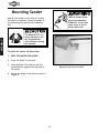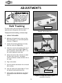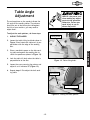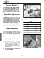
1
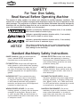
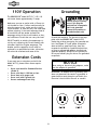
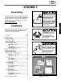
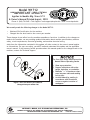
Model W1712
***IMPORTANT UPDATE***
Applies to Models Mfg. Since 3/12
& Owner's Manual Printed August, 2003
Phone #: (360) 734-3482 • Tech Support: [email protected] • Web: www.shopfox.biz
We recently made the following changes to the Model W1712:
•
•
Obtained CSA Certification for the machine.
Changed the disc dust hood to the correct part number.
These changes do not affect how the machine assembles or functions. In addition to the changes we
made to the machine, we are providing updated information about machine specifications, machine
safety, circuit requirements, electrical grounding, and machine electrical wiring.
Aside from the information contained in this update, all other content in the owner's manual applies
to this machine. For your own safety, you MUST read and understand this update and the applicable
owner's manual. If you have any further questions about this manual update or the changes made to the
machine, contact our Technical Support.
6
Figure 1. Disc dust hood is part number 6
(changed from part number 70).
For Your Own Safety Read Instruction
Manual Before Operating Sander
a) Wear eye protection.
b) Support workpiece with miter
gauge, backstop, or worktable.
c) Maintain 1⁄16" in maximum clearance between table and sanding
belt or disc.
d) Avoid kickback by sanding in
accordance with directional
arrows or against rotation of
sandpaper.
COPYRIGHT © MARCH, 2012 BY WOODSTOCK INTERNATIONAL, INC.
255023
WARNING: NO PORTION OF THIS MANUAL MAY BE REPRODUCED IN ANY SHAPE OR FORM WITHOUT
THE WRITTEN APPROVAL OF WOODSTOCK INTERNATIONAL, INC.
#14867TS Printed in Taiwan
MODEL W1712
Motors
Main
1-1/2 HP 6/12" COMBINATION DISC/BELT SANDER
Type......................................................................... TEFC Capacitor Start Induction
Horsepower........................................................................................... 1-1/2 HP
Voltage...................................................................................................... 110V
Phase.............................................................................................. Single-Phase
Amps....................................................................................................... 10.5A
Speed.................................................................................................. 1725 RPM
Cycle....................................................................................................... 60 Hz
Number of Speeds............................................................................................. 1
Power Transfer ................................................................................... Direct Drive
Bearings............................................................. Shielded and Permanently Lubricated
Main Specifications
Table Info
Table Tilt............................................................................................. 0-45 deg.
Miter Gauge Slot Width................................................................................ 3/4 in.
Miter Gauge Slot Height............................................................................... 3/8 in.
Belt Table Length................................................................................... 12-3/8 in.
Belt Table Width........................................................................................... 7 in.
Belt Table Thickness...................................................................................... 1 in.
Disc Table Length................................................................................... 17-5/8 in.
Disc Table Width......................................................................................... 10 in.
Disc Table Thickness...................................................................................... 1 in.
Belt Info
Sanding Belt Width........................................................................................ 6 in.
Sanding Belt Length...................................................................................... 48 in.
Sanding Belt Speed.................................................................................. 1066 FPM
Belt Arm Tilt........................................................................................ 0 - 90 deg.
Height Belt Arm Horizontal........................................................................ 14-1/2 in.
Height Belt Arm Vertical........................................................................... 29-1/2 in.
Belt Release..................................................................................... Quick Release
Drive Roller Type................................................................................... Aluminum
Drive Roller Length.................................................................................. 6-1/4 in.
Drive Wheel Diameter............................................................................... 2-1/4 in.
Idler Roller Type.................................................................................... Aluminum
Idler Roller Length................................................................................... 6-1/4 in.
Idler Roller Diameter................................................................................ 2-1/4 in.
Spindle Info
Arbor Size................................................................................................ 3/4 in.
Total Arbor Length........................................................................................ 6 in.
Model W1712 Machine Specifications, Page 1 of 3
Disc Info
Sanding Disc Diameter................................................................................... 12 in.
Sanding Disc Speed.................................................................................. 1725 RPM
Platen Info
Platen
Platen
Platen
Platen
Type........................................................................................... Cast Iron
Length........................................................................................ 14-1/2 in.
Width............................................................................................... 6 in.
Travel............................................................................................ 1/4 in.
Construction
Base................................................................................................. Sheet Metal
Table......................................................................................... Ground Cast Iron
Frame............................................................................................... Sheet Metal
Disc..................................................................... Computer Balanced Cast Aluminum
Miter Gauge............................................................ Die Cast Aluminum/Aluminum Bar
Paint............................................................................................ Powder Coated
Other
No. Of Dust Ports.............................................................................................. 2
Dust Port Size...................................................................................... 2, 2-1/2 in.
Product Dimensions
Weight.......................................................................................................... 145 lbs.
Width (side-to-side) x Depth (front-to-back) x Height........................ 32-1/2 x 16-1/2 x 29-1/2 in.
Footprint (Length x Width).............................................................................. 17 x 14 in.
Shipping Dimensions
Type......................................................................................................... Cardboard
Content........................................................................................................ Machine
Weight.......................................................................................................... 178 lbs.
Length x Width x Height........................................................................... 30 x 28 x 18 in.
Electrical
Power Requirement.................................................................... 110V, Single-Phase, 60 Hz
Full-Load Current Rating....................................................................................... 10.5A
Minimum Circuit Size............................................................................................. 15A
Switch......................................................................... ON/OFF Toggle w/Safety Lock Key
Switch Voltage.................................................................................................... 110V
Cord Length....................................................................................................... 5 ft.
Cord Gauge.................................................................................................... 14 AWG
Plug Included....................................................................................................... Yes
Included Plug Type............................................................................................... 5-15
Other
ISO 9001 Factory .................................................................................................. Yes
Country Of Origin ............................................................................................. Taiwan
Warranty ........................................................................................................ 2 Year
Serial Number Location ................................................................. Machine Label on Motor
Customer Assembly & Setup Time ..................................................................... 45 Minutes
Model W1712 Machine Specifications, Page 2 of 3
Model W1712 (Mfg. Since 3/12)
SAFETY
For Your Own Safety,
Read Manual Before Operating Machine
The purpose of safety symbols is to attract your attention to possible hazardous conditions. This
manual uses a series of symbols and signal words intended to convey the level of importance of the
safety messages. The progression of symbols is described below. Remember that safety messages by
themselves do not eliminate danger and are not a substitute for proper accident prevention measures—this responsibility is ultimately up to the operator!
Indicates an imminently hazardous situation which, if not avoided,
WILL result in death or serious injury.
Indicates a potentially hazardous situation which, if not avoided,
COULD result in death or serious injury.
Indicates a potentially hazardous situation which, if not avoided,
MAY result in minor or moderate injury.
NOTICE
This symbol is used to alert the user to useful information about
proper operation of the equipment, and/or a situation that may
cause damage to the machinery.
Standard Machinery Safety Instructions
OWNER’S MANUAL. Read and understand this
owner’s manual BEFORE using machine.
Untrained users can be seriously hurt.
HEARING PROTECTION. Always wear hearing
protection when operating or observing
loud machinery. Extended exposure to this
noise without hearing protection can cause
permanent hearing loss.
EYE PROTECTION. Always wear ANSI-approved
safety glasses or a face shield when operating
or observing machinery to reduce the risk of
eye injury or blindness from flying particles.
Everyday eyeglasses are not approved safety
glasses.
MENTAL ALERTNESS. Be mentally alert when
running machinery. Never operate under the
influence of drugs or alcohol, when tired, or
when distracted.
HAZARDOUS DUST. Dust created while using
machinery may cause cancer, birth defects,
or long-term respiratory damage. Be aware
of dust hazards associated with workpiece
materials, and always wear a NIOSH-approved
respirator to reduce your risk.
DISCONNECTING POWER SUPPLY. Always
disconnect machine from power supply before
servicing, adjusting, or changing cutting tools
(bits, blades, cutters, etc.). Make sure switch
is in OFF position before reconnecting to avoid
an unexpected or unintentional start.
WEARING PROPER APPAREL. Do not wear
clothing, apparel, or jewelry that can become
entangled in moving parts. Always tie back
or cover long hair. Wear non-slip footwear to
avoid accidental slips which could cause a loss
of workpiece control.
DANGEROUS ENVIRONMENTS. Do not use
machinery in wet or rainy locations, cluttered
areas, around flammables, or in poorly-lit
areas. Keep work area clean, dry, and welllighted to minimize risk of injury.
-4-
Model W1712 (Mfg. Since 3/12)
APPROVED OPERATION. Untrained operators
can be seriously hurt by machinery. Only
allow trained or properly supervised people
to use machine. When machine is not being
used, disconnect power, remove switch keys,
or lock-out machine to prevent unauthorized
use—especially around children. Make
workshop kid proof!
STABLE MACHINE. Unexpected movement during
operations greatly increases the risk of injury
and loss of control. Verify machines are
stable/secure and mobile bases (if used) are
locked before starting.
FORCING MACHINERY. Do not force machine. It
will do the job safer and better at the rate for
which it was designed.
ONLY USE AS INTENDED. Only use machine for
its intended purpose. Never modify or alter
machine for a purpose not intended by the
manufacturer or serious injury may result!
AWKWARD POSITIONS. Keep proper footing and
balance at all times when operating machine.
Do not overreach! Avoid awkward hand
positions that make workpiece control difficult
or increase the risk of accidental injury.
USE RECOMMENDED ACCESSORIES. Consult
this owner’s manual or the manufacturer for
recommended accessories. Using improper
accessories will increase the risk of serious
injury.
UNATTENDED OPERATION. Never leave machine
running while unattended. Turn machine off
and ensure all moving parts completely stop
before walking away.
CHILDREN & BYSTANDERS. Keep children and
bystanders a safe distance away from work
area. Stop using machine if children or
bystanders become a distraction.
MAINTAIN WITH CARE. Follow all maintenance
instructions and lubrication schedules to
keep machine in good working condition. An
improperly maintained machine may increase
the risk of serious injury.
REMOVE ADJUSTING TOOLS. Never leave
adjustment tools, chuck keys, wrenches, etc.
in or on machine—especially near moving
parts. Verify removal before starting!
CHECK DAMAGED PARTS. Regularly inspect
machine for damaged parts, loose bolts,
mis-adjusted or mis-aligned parts, binding,
or any other conditions that may affect safe
operation. Always repair or replace damaged
parts, wires, cords, or plugs before operating
machine.
SECURING WORKPIECE. When required, use
clamps or vises to secure workpiece. A secured
workpiece protects hands and frees both of
them to operate the machine.
FEED DIRECTION. Unless otherwise noted, feed
work against the rotation of blades or cutters.
Feeding in the same direction of rotation may
pull your hand into the cut.
MAINTAIN POWER CORDS. When disconnecting
cord-connected machines from power, grab
and pull the plug—NOT the cord. Pulling the
cord may damage the wires inside. Do not
handle the cord/plug with wet hands. Avoid
cord damage by keeping it away from heated
surfaces, high traffic areas, harsh chemicals,
and wet or damp locations.
GUARDS & COVERS. Guards and covers can
protect you from accidental contact with
moving parts or flying debris. Make sure
they are properly installed, undamaged, and
working correctly before using machine.
EXPERIENCING DIFFICULTIES. If at any time you
are experiencing difficulties performing the
intended operation, stop using the machine!
Contact our Technical Support for help at
(360) 734-3482.
NEVER STAND ON MACHINE. Serious injury or
accidental contact with cutting tool may
occur if machine is tipped. Machine may be
damaged.
-5-
Model W1712 (Mfg. Since 3/12)
Additional Safety for Sanders
FEED RATE. Never jam a workpiece against the
sanding surface. This can cause the workpiece
to kick back or damage the machine. Firmly
hold the workpiece and ease it against the
spindle using light pressure.
SANDING DISCS/BELTS. Worn or damaged sanding discs/belts can tear apart and become
entangled in the spindle or be thrown from the
machine, resulting in personal injury or property damage. Replace sanding discs/belts as
required.
AVOIDING ENTANGLEMENT. Keep loose clothing
articles such as sleeves, belts or jewelry items
away from the spindle. These items could get
entangled in the sanding disc/belt, resulting
in serious personal injury. Never wear gloves
when operating the sander.
DUST COLLECTION. Never operate the sander
without an adequate dust collection system
in place and running. Proper dust collection
reduces dust in the work area, which decreases
the risk of long-term respiratory damage.
HAND PLACEMENT. Do not place hands near, or in
contact with, sanding surfaces during operation
to avoid personal injury.
DIRECTION. Never sand tapered or pointed stock
with the point facing the feed direction to
avoid the workpiece being thrown from the
machine.
WORKPIECE HANDLING. Hold the workpiece with
both hands (or use a miter gauge or appropriate holding jig) and firmly on the table or
backstop to maintain control while sanding
to reduce the likelihood of losing control of
the workpiece and having it thrown from the
machine.
POWER DISCONNECT. Disconnect the machine
from the power source before changing the
sanding disc/sleeve to avoid injuries in the
event of an accidental startup.
RESPIRATOR USE. Always use a respirator that
is approved for wood dust when using this
machine to reduce the risk of short and long
term respiratory illness. A dust collector is not
an adequate substitute.
FOREIGN MATERIAL. Always inspect stock for
nails, staples, knots, and other imperfections
that could be dislodged and thrown from the
machine during sanding operations.
READ and understand this
entire manual before using
this machine. Serious personal injury may occur
if safety and operational
information is not understood and followed. DO
NOT risk your safety by
not reading!
Use this and other machinery with caution
and respect. Always consider safety first,
as it applies to your individual working
conditions. No list of safety guidelines can
be complete—every shop environment is
different. Failure to follow guidelines could
result in serious personal injury, damage
to equipment or poor work results.
-6-
Model W1712 (Mfg. Since 3/12)
ELECTRICAL
Circuit Requirements
This machine must be connected to the correct size and
type of power supply circuit, or fire or electrical damage
may occur. Read through this section to determine if an
adequate power supply circuit is available. If a correct
circuit is not available, a qualified electrician MUST install
one before you can connect the machine to power.
The machine must be properly set up
before it is safe to operate. DO NOT
connect this machine to the power
source until instructed to do later in
this manual.
A power supply circuit includes all electrical equipment
between the breaker box or fuse panel in the building
and the machine. The power supply circuit used for
this machine must be sized to safely handle the fullload current drawn from the machine for an extended
period of time. (If this machine is connected to a circuit
protected by fuses, use a time delay fuse marked D.)
Full-Load Current Rating
The full-load current rating is the amperage a machine
draws at 100% of the rated output power. On machines
with multiple motors, this is the amperage drawn by the
largest motor or sum of all motors and electrical devices
that might operate at one time during normal operations.
Full-Load Current Rating at 110V.................10.5 Amps
Circuit Requirements for 110V
This machine can be converted to operate on a 110V
power supply (details about voltage conversion can be
found later in this manual). The 110V power supply circuit
must have a verified ground and meet the requirements
that follow:
Circuit Type................ 110V/120V, 60 Hz, Single-Phase
Circuit Size.............................................. 15 Amps
Plug/Receptacle..................................... NEMA 5-15
-7-
Incorrectly wiring or grounding this
machine can cause electrocution, fire,
or machine damage. To reduce this risk,
only an electrician or qualified service
personnel should do any required
electrical work on this machine.
NOTICE
The circuit requirements listed in this
manual apply to a dedicated circuit—
where only one machine will be running
at a time. If this machine will be
connected to a shared circuit where
multiple machines will be running at
the same time, consult a qualified
electrician to ensure that the circuit is
properly sized for safe operation.
Model W1712 (Mfg. Since 3/12)
Grounding Requirements
This machine MUST be grounded. In the event of certain
types of malfunctions or breakdowns, grounding provides
a path of least resistance for electric current to travel—in
order to reduce the risk of electric shock.
Improper connection of the equipment-grounding wire will
increase the risk of electric shock. The wire with green
insulation (with/without yellow stripes) is the equipmentgrounding wire. If repair or replacement of the power
cord or plug is necessary, do not connect the equipmentgrounding wire to a live (current carrying) terminal.
110V
GROUNDED
5-15 RECEPTACLE
Grounding Prong
5-15 PLUG
Neutral Hot
Figure 2. NEMA 5-15 plug & receptacle.
Check with a qualified electrician or service personnel
if you do not understand these grounding requirements,
or if you are in doubt about whether the tool is
properly grounded. If you ever notice that a cord or
plug is damaged or worn, disconnect it from power, and
immediately replace it with a new one.
For 110V Connection
This machine is equipped with a power cord that has an
equipment-grounding wire and NEMA 5-15 grounding plug.
The plug must only be inserted into a matching receptacle
(see Figure) that is properly installed and grounded in
accordance with local codes and ordinances.
Extension Cords
We do not recommend using an extension cord with this
machine. Extension cords cause voltage drop, which may
damage electrical components and shorten motor life.
Voltage drop increases with longer extension cords and
the gauge smaller gauge sizes (higher gauge numbers
indicate smaller sizes).
Any extension cord used with this machine must contain a
ground wire, match the required plug and receptacle, and
meet the following requirements:
Minimum Gauge Size at 110V....................... 14 AWG
Maximum Length (Shorter is Better).................50 ft.
-8-
DO NOT modify the provided plug or
use an adapter if the plug will not
fit the receptacle. Instead, have an
electrician install the proper receptacle
on a power supply circuit that meets
the requirements for this machine.
Model W1712 (Mfg. Since 3/12)
Wiring Diagram
WARNING!
Disconnect power
before performing
adjustments, maintenance, or service.
Neutral
Hot
G
Ground
PADDLE SWITCH
(Viewed From Behind)
23
24
13
14
110V
Nema 5-15 Plug
(As Recommended)
110V Motor
Ground
Start
Capacitor
150MFD
125VAC
Run
Capacitor
45MFD
250VAC
-9-
High Quality Machines and Tools
Woodstock International, Inc. carries thousands of products designed
to meet the needs of today's woodworkers and metalworkers.
Ask your dealer about these fine products:
MODEL W1712
12" Disc & 6" Belt Sander
INSTRUCTION MANUAL
Phone: 1-360-734-3482 • On-Line Technical Support: [email protected]
COPYRIGHT © August, 2003 BY WOODSTOCK INTERNATIONAL, INC.
WARNING: NO PORTION OF THIS MANUAL MAY BE REPRODUCED IN ANY SHAPE OR FORM WITHOUT
THE WRITTEN APPROVAL OF WOODSTOCK INTERNATIONAL, INC.
Printed in Taiwan
WARNING
Some dust created by power sanding, sawing, grinding, drilling, and other construction activities contains chemicals known to the State of California to
cause cancer, birth defects or other reproductive
harm. Some examples of these chemicals are:
• Lead from lead-based paints.
• Crystalline silica from bricks, cement, and
other masonry products.
• Arsenic and chromium from chemically
treated lumber.
Your risk from these exposures varies, depending on
how often you do this type of work. To reduce your
exposure to these chemicals: work in a well ventilated area, and work with approved safety equipment, such those dust masks that are specially
designed to filter out microscopic particles.
INTRODUCTION ............................................................................................2
SAFETY ......................................................................................................4
ASSEMBLY ..................................................................................................9
ADJUSTMENTS ............................................................................................14
Belt Tracking ..................................................................................................14
Table Angle Adjustment......................................................................................15
Disc Table Alignment ........................................................................................16
ADJUSTMENTS
Unpacking ........................................................................................................9
Inventory ........................................................................................................9
Shop Preparation ..............................................................................................10
Dust Collection ................................................................................................10
Initial Cleaning ................................................................................................10
Cabinet Assembly..............................................................................................11
Mounting Sander ..............................................................................................12
Installing Table ................................................................................................13
ASSEMBLY
Standard Safety Instructions ..................................................................................4
Know Your Machine ............................................................................................6
Safety Instructions for Your Sander..........................................................................7
110V Operation..................................................................................................8
Extension Cords ................................................................................................8
Grounding ........................................................................................................8
SAFETY
About Your New Sander........................................................................................2
Woodstock Service and Support ..............................................................................2
Warranty and Returns ..........................................................................................3
Specifications ..................................................................................................3
INTRODUCTION
CONTENTS
OPERATIONS ..............................................................................................17
Test Run ........................................................................................................17
Miter Sanding ..................................................................................................18
Power Switch ..................................................................................................18
Belt/Disc Selection ............................................................................................18
Disc Sanding ....................................................................................................19
Flat Sanding ..................................................................................................19
Changing Sanding Belt ........................................................................................21
Changing Sanding Disc Paper ................................................................................22
OPERATIONS
MAINTENANCE ............................................................................................23
MAINTENANCE
General..........................................................................................................23
Lubrication ....................................................................................................23
Sanding Surfaces ..............................................................................................23
PARTS ......................................................................................................24
TROUBLESHOOTING......................................................................................28
PARTS
USE THE QUICK GUIDE PAGE LABELS TO SEARCH OUT INFORMATION FAST!
INTRODUCTION
INTRODUCTION
About Your New Sander
Your new SHOP FOX® Model W1712 12" Disc and 6" Belt Sander is specially designed to provide many
years of trouble-free service. Close attention to engineering detail, ruggedly built parts, and a rigid
quality control program assure safe and reliable operation.
The Model W1712 features a 11⁄2 HP, 110V motor. It also features a heavy-duty cabinet stand, two tilting precision-ground cast iron tables, and dual dust ports.
For more features and details, refer to the Specifications sub-section in this manual.
Woodstock International, Inc. is committed to customer satisfaction in providing this manual. It is our
intent to include all the information necessary for safety, ease of assembly, practical use and durability of this product.
If you need the latest edition of this manual, you can download it from http://www.shopfox.biz.
If you still have questions after reading the latest manual, or if you have comments please contact us at:
Woodstock International, Inc.
Attn: Technical Support Department
P.O. Box 2309
Bellingham, WA 98227
Woodstock Service and Support
We stand behind our machines! In the event that a defect is found, parts are missing or questions arise
about your machine, please contact Woodstock International Service and Support at 1-360-734-3482 or
send e-mail to: [email protected]. Our knowledgeable staff will help you troubleshoot problems, order parts or arrange warranty returns.
-2-
Woodstock International, Inc. warrants all SHOP FOX® machinery to be free of defects from workmanship and materials for a period of 2 years from the date of original purchase by the original owner.
This warranty does not apply to defects due directly or indirectly to misuse, abuse, negligence or accidents, lack of maintenance, or to repairs or alterations made or specifically authorized by anyone
other than Woodstock International, Inc.
Woodstock International, Inc. will repair or replace, at its expense and at its option, the SHOP FOX®
machine or machine part which in normal use has proven to be defective, provided that the original
owner returns the product prepaid to the SHOP FOX® factory service center or authorized repair
facility designated by our Bellingham, WA office, with proof of their purchase of the product within 2
years, and provides Woodstock International, Inc. reasonable opportunity to verify the alleged defect
through inspection. If it is determined there is no defect, or that the defect resulted from causes not
within the scope of Woodstock International Inc.'s warranty, then the original owner must bear the
cost of storing and returning the product.
This is Woodstock International, Inc.'s sole written warranty and any and all warranties that may be
implied by law, including any merchantability or fitness, for any particular purpose, are hereby limited to the duration of this written warranty. We do not warrant that SHOP FOX® machinery complies
with the provisions of any law or acts. In no event shall Woodstock International, Inc.'s liability under
this warranty exceed the purchase price paid for the product, and any legal actions brought against
Woodstock International, Inc. shall be tried in the State of Washington, County of Whatcom. We shall
in no event be liable for death, injuries to persons or property or for incidental, contingent, special or
consequential damages arising from the use of our products.
Every effort has been made to ensure that all SHOP FOX® machinery meets high quality and durability standards. We reserve the right to change specifications at any time because of our commitment to
continuously improve the quality of our products.
Specifications
Motor Size ................................................................11⁄2 HP, 110V Single-Phase
Motor Speed....................................................................................1725 RPM
Sanding Belt ......................................................................................6" x 48"
Belt Speed ......................................................................................878 FPM
Sanding Disc............................................................................................12"
Disc Speed......................................................................................1725 RPM
Table (Disc) ..................................................................................171⁄2" x 10"
Stand ..........................................................Cabinet-Style, Powder-Coated Paint
Power Transfer ............................................................................Direct Drive
Bearings ..........................................................Sealed & Lubricated Ball Bearings
Switch ................................................ ON/OFF Paddle Switch, w/ Safety Lock Key
Shipping Weight ................................................................................178 lbs.
-3-
INTRODUCTION
INTRODUCTION
Warranty and Returns
SAFETY
SAFETY
READ MANUAL BEFORE OPERATING MACHINE.
FAILURE TO FOLLOW INSTRUCTIONS BELOW WILL
RESULT IN PERSONAL INJURY.
Indicates an imminently hazardous situation which, if not avoided, WILL
result in death or serious injury.
Indicates a potentially hazardous situation which, if not avoided, COULD
result in death or serious injury.
Indicates a potentially hazardous situation which, if not avoided, MAY
result in minor or moderate injury, MAY result in property damage.
NOTICE
This symbol is used to alert the user to useful information about proper
operation of the equipment.
Standard Safety Instructions
1. Thoroughly read the instruction manual before operating your machine. Learn the applications,
limitations and potential hazards of this machine. Keep manual in a safe, convenient place for future
reference.
2. Keep work area clean and well lit. Clutter and inadequate lighting invite potential hazards.
3. Ground all tools. If a machine is equipped with a three-prong plug, it must be plugged into a threehole grounded electrical receptacle or grounded extension cord. If you are using an adapter to aid
in accommodating a two-hole receptacle, screw adapter to a known ground.
4. Wear eye protection at all times. Use safety glasses with side shields or safety goggles that meet
the appropriate standards of the American National Standards Institute (ANSI).
5. Avoid dangerous environments. DO NOT operate this machine in wet or open flame environments.
Airborne dust particles could cause an explosion and severe fire hazard.
6. Ensure all guards are securely in place and in working condition.
7. Make sure the machine power switch is in the OFF position before connecting power to machine.
8. Keep the work area clean, free of clutter, grease, etc.
9. Keep children and visitors away. Visitors should be kept at a safe distance while operating unit.
10. Childproof your workshop with padlocks, master switches or by removing starter keys.
11. Stop and disconnect the machine when cleaning, adjusting or servicing.
-4-
12. DO NOT force tool. The machine will do a safer and better job at the rate for which it was designed.
13. Use correct tool. DO NOT force machine or attachment to do a job for which it was not designed.
14. Wear proper apparel. DO NOT wear loose clothing, neck ties, gloves, jewelry, and secure long hair
away from moving parts.
16. Avoid using an extension cord. But if you must, examine the extension cord to ensure it is in good
condition. Use TABLE 1 below to determine the correct length and gauge of extension cord needed
for your particular needs. The amp rating of the motor can be found on its nameplate. If the motor
is dual voltage, be sure to use the amp rating for the voltage you will be using. If you use an extension cord with an undersized gauge or one that is too long, excessive heat will be generated within
the circuit, increasing the chance of a fire or damage to the circuit. Always use an extension cord
that uses a ground pin and connected ground wire. Immediately replace a damaged extension cord.
17. Keep proper footing and balance at all times and lock mobile base from rolling freely before using
your machine.
18. DO NOT leave machine unattended. Wait until it comes to a complete stop before leaving the area.
19. Perform machine maintenance and care. Follow lubrication and accessory attachment instructions
in the manual.
20. Keep machine away from open flame. Operating machines near pilot lights or open flames creates
a high risk if dust is dispersed in the area. Dust particles and an ignition source may cause an explosion. DO NOT operate the machine in high-risk areas, including but not limited to, those mentioned
above.
21. If at any time you are experiencing difficulties performing the intended operation, stop using the
machine! Contact our service department or ask a qualified expert how the operation should be performed.
22. Habits are hard to break. Develop good habits in your shop and consistent safety practices will
become second-nature to you.
TABLE 1.
Extension Cord Requirements
Amp Rating
0-6
7-10
11-12
13-16
17-20
21-30
Length
25ft
#16
#16
#16
#14
#12
#10
Operating this equipment creates the
potential for flying debris to cause eye
injury. Always wear safety glasses or goggles when operating equipment. Everyday
glasses or reading glasses only have impact
resistant lenses, they are not safety glasses.
Be certain the safety glasses you wear meet
the appropriate standards of the American
National Standards Institute (ANSI).
And Gauge
50ft 100ft
#16
#16
#16
#14
#16
#14
#12
#12
#12
#10
#10
No
-5-
SAFETY
15. Remove adjusting keys, rags, and tools. Before turning the machine on, make it a habit to check
that all adjusting keys and wrenches have been removed.
SAFETY
Know Your Machine
An important part of safety is knowing your machine and its components. Please take the time to learn
the items shown below in Figure 1. The letters in the picture correspond to the following descriptions
in the list.
A
C
D
B
K
E
J
F
G
I
H
Figure 1. Machine Features.
A.
B.
C.
D.
E.
F.
G.
H.
I.
J.
K.
Sanding Belt
Motor
Paddle Switch with Safety Key
12" Sanding Disc
Sanding Disc Table
Miter Gauge
Sanding Disc Dust Port
Cabinet Stand
Table Tilting Knobs
Sanding Belt Dust Port
Sanding Belt Table
-6-
Safety Instructions for Your Sander
•
ALWAYS keep bystanders away when sanding.
•
ALWAYS secure aprons, clothing, and long hair away from all sander moving parts.
•
ALWAYS use a respirator along with a dust collection system when sanding. Dust from some wood
is toxic, so make sure you research the dangers of the specific species of wood you will sand.
•
ALWAYS keep your hands away from the sanding belt and disc during operation.
•
ALWAYS wear eye and hearing protection.
•
ALWAYS feed the workpiece into the sander using light pressure, so you do not overload
the sander. Never force the workpiece into the sander.
•
ALWAYS shut the sander down, let the belt come to a complete stop, and disconnect
power or engage applicable safety-lock devices before you service, adjust, troubleshoot, or leave the machine unattended.
•
ALWAYS keep this machine in correct adjustment and properly serviced.
•
ALWAYS replace the sandpaper when it is worn, and only use undamaged sandpaper.
•
ALWAYS inspect the workpiece for nails, staples, knots, imbedded stones, and other
material that could be dislodged and thrown from the machine during sanding operations.
•
NEVER attempt to clear a jammed workpiece while the sander is running.
•
NEVER sand if there is any doubt about the stability or integrity of the workpiece.
•
NEVER sand more than one workpiece at a time.
•
NEVER sand tapered or pointed stock with the point facing the feed direction.
•
NEVER leave the machine running unattended.
•
NEVER operate the sander without an adequate dust collection system in place and running.
-7-
SAFETY
USE this and other machinery with caution
and respect, and always consider safety
first, as it applies to your individual working conditions. Remember, no list of safety
guidelines can be complete, and every
shop environment is different. Failure to
follow guidelines can result in serious personal injury, damage to equipment and/or
poor work results.
READ and understand this
entire instruction manual
before using this machine.
Serious personal injury
may occur if safety and
operational information is
not understood and followed. DO NOT risk your
safety by not reading!
110V Operation
Grounding
SAFETY
The SHOP FOX® Model W1712 11⁄2 HP, 110
volt motor draws approximately 12 amps.
Serious injury or fire may
occur if you plug this
machine into a receptacle
that is not grounded.
Connect this machine to
grounded outlets only!
Make sure you use an outlet with a 15 amp circuit breaker or fuse. If other machines may be
using the same circuit, make sure the circuit,
circuit breaker, or fuse can carry the total load
without tripping. If the total amperage load of
all machines and the sander exceeds the
amperage rating of the circuit breaker or fuse,
use a different circuit that can carry the load.
Ground this machine! The electrical cord supplied with the SHOP FOX® Model W1712
Sander has a three prong plug for grounded outlets. See Figure 2. If your power receptacle
does not have a ground pin hole, have the
receptacle replaced by a qualified electrician,
or have an appropriate adapter installed and
grounded properly. NEVER cut the ground pin
off so your sander plug fits into a non-grounded
receptacle.
DO NOT modify an existing low-amperage circuit by only replacing the circuit breaker with
a breaker rated for a higher amperage. The
breaker and the complete circuit must be
replaced by a qualified electrician, otherwise
the wires can overheat and cause a fire.
Extension Cords
If you must use an extension cord with the
Model W1712, please follow these requirements:
•
•
•
•
•
NOTICE
When using an electrical plug adapter, make
sure the adapter is grounded.
Use a cord rated for Standard Service
(Grade S).
Use a cord that is 100 feet or less.
Use a least a 16 gauge cord.
Use a cord with a ground pin.
Use an undamaged cord only.
Remember, an adapter with a grounding wire
does not guarantee the sander is grounded. A
ground source must always be verified in the
electrical circuit within the wall or conduit.
Figure 2. NEMA-style 5-15 plug and receptacle.
-8-
ASSEMBLY
Unpacking
Inventory
Layout and inventory the package contents listed below and familiarize yourself with the
components to ease assembly.
Item
The Model W1712 is a
heavy machine at 165
lbs. Use assistance
when lifting or moving
the machine.
Qty.
A. Sander Unit ....................................1
B. Cabinet Stand ..................................1
• Side Panel L/R ................................2
• Front/Rear Panel ..............................2
C. Table Hardware Bag ..........................1
- Cap Screw 5⁄16"-18 x 3⁄4" ................2
- Lock Nut 5⁄16"-18 ..........................2
- Flat Washer 1⁄4" ..........................2
- Knob Bolt M6-1 x 15......................2
D. 12" Disc Sanding Table ........................1
E. Belt Sanding Table ............................1
F. Main Hardware Bag ............................1
• Cabinet Stand Hardware Bag ................1
- Hex Bolt 5⁄16"-18 x 3⁄8" ..................8
- Hex Bolt 5⁄16"-18 x 1" ....................2
- Hex Nut 5⁄16" ..............................8
- Flat Washer 5⁄16" ........................18
- Lock Washer 5⁄16"........................10
- 6MM Allen Wrench........................1
• Floor Pad Bag ..................................1
- Floor Pads ................................4
- Phillips Head Screw 3⁄16"-18 x 5⁄8" ....4
- Flat Washer 5⁄16" ..........................4
- Hex Nut 5⁄16" ..............................4
• Accessories Bag ................................1
- Belt Tension Lever ......................1
- Screwdriver................................1
- Knob Bolt M8-1.25 x 20 ..................1
- Stop Fence ................................1
G. Miter Gauge Assembly ........................1
UNPLUG power cord
before you do any assembly or adjustment tasks!
Otherwise, serious personal injury to you or
others may occur!
A
D
F
C
G
E
Figure 3. Inventory.
-9-
B
ASSEMBLY
Read and understand this
entire instruction manual
before performing any
operations with your
machine. Serious personal
injury may occur if safety
and operational information is not understood
and followed.
The Model W1712 was carefully packed when it
left our warehouse. If you receive it damaged or
missing any parts, please contact Woodstock
International Service and Support at 1-360-7343482 or send e-mail to:
[email protected].
Shop Preparation
Initial Cleaning
The exposed and unpainted sander surfaces are
coated with a waxy oil to prevent rust during
storage and shipment. DO NOT use chlorine
based solutions or solvents to remove this waxy
oil or you will damage the painted surfaces.
Remove the waxy oil with a solvent based
degreaser before you use the sander. Always
follow all usage and safety instructions of the
product that you are using.
ASSEMBLY
ONLY ALLOW TRAINED
PEOPLE in your shop! Make
sure shop entrances are
locked and machines are
correctly turned off with
lock-out devices when not
in use. Otherwise, injury
or death can occur.
•
Lighting: Lighting should be bright enough
to eliminate shadows and prevent eye
strain.
•
Working Clearances: Consider your current
and future shop needs with respect to the
safe operation of this machine.
•
Outlets: Make sure the electrical circuits
have the capacity to handle the amperage
requirements for your Model W1712. Refer
to page 8 for more information. Electrical
outlets should be located near the sander,
so power or extension cords are clear of
high-traffic areas.
DO NOT use flammables
such as gas or other
petroleum-based solvents
to clean your machine.
These products have low
flash points and present
the risk of explosion and
severe personal injury!
DO NOT smoke while
using cleaning solvents.
Smoking may cause
explosion or risk of fire
when exposed to these
products!
Dust Collection
Some wood dust may
cause allergic reactions
or respiratory illness.
Use a dust collection system and respirator in
your shop to help protect
yourself from these longterm hazards.
ALWAYS work in a well
ventilated area when
using solvents with
fumes, and keep away
from any potential ignition sources (pilot
lights). Most solvents
used to clean machinery
are toxic when inhaled
or ingested. Always dispose of waste rags in a
sealed container to
make sure they do not
cause fire or environmental hazards.
For information on the correct dust collection
components for sanders, contact your
Woodstock International dealer for a copy of
the Dust Collection Basics handbook and available accessories.
-10-
Cabinet Assembly
The Model W1712 mounts onto a heavy-duty
formed sheet steel cabinet stand. Use the
hardware in the cabinet hardware bag to complete this assembly.
Mounting Locations
Side Panel
To assemble the cabinet stand, do these
steps:
1.
Assemble the cabinet panels together as
shown in Figure 4 with the supplied 5⁄16"18 x 3⁄4" hex bolts, 5⁄16" flat washers, 5⁄16"
lock washers and 5⁄16" hex nuts.
Attach the remaining side panel.
3.
Secure the rubber feet to the bottom corners of the cabinet stand with the floor
pad hardware bag as shown in Figure 5.
Figure 4. Cabinet assembly.
Figure 5. Rubber feet installed.
-11-
ASSEMBLY
2.
Front/Rear Panels
Mounting Sander
UNPLUG sander before
you do any assembly!
Otherwise, serious personal injury to you or
others may occur!
ASSEMBLY
Mounting the sander to the stand will require
the help of an assistant. Secure the sander to
the stand using the cabinet stand hardware
bag.
The Model W1712 is a
heavy machine at 165
lbs. Use assistance
when lifting or moving
the machine.
To mount the sander, do these steps:
1. KEEP THE SANDER UNPLUGGED!
2.
Place the sander on the stand.
3.
Align the holes in the cabinet with the
pre-drilled and tapped mounting holes in
the sander.
4.
Figure 6. Mounting the sander.
Secure the sander to the stand as shown in
Figure 6.
-12-
Installing Table
The sanding belt table comes assembled on the
W1712, but the sanding disc table needs to be
installed on the sander.
To install the sanding disc table, do these
steps:
1. KEEP THE SANDER UNPLUGGED!
Align the sanding table mounting holes
with the threaded holes in the bracket.
3.
Secure the sanding table, as shown in
Figure 7, with the cap screws supplied in
the table hardware bag.
4.
Install the table tilt control knobs (Figure
8).
Figure 7. Installing table.
Figure 8. Installed tilting knobs.
-13-
ASSEMBLY
2.
ADJUSTMENTS
UNPLUG the power cord
when making any adjustments on this machine!
Otherwise, serious personal injury to you or
others may occur!
Belt Tracking
Locking Lever
The belt tracking must be adjusted correctly to
make the belt ride parallel with the table.
Figure 9. Belt locking lever.
ADJUSTMENTS
To adjust the belt tracking, do these steps:
1.
UNPLUG THE SANDER!
2.
Make sure all guards are in place and the
belt locking lever is in the locked position
as shown in Figure 9.
3.
Loosen the knurled adjustment nut away
from the roller pin (Figure 10).
4.
Check the current belt position and note if
it needs to move left or right. Figure 11
shows a properly tracked belt with 1⁄16" of
the roller exposed on each side.
Adjustment Nut
Tension Bolt
Roller Pin
Figure 10. Tracking adjustment system.
5.
Adjust the tension bolt clockwise to make
the belt ride to the left, and adjust
counter-clockwise to make the belt ride to
the right.
6.
Plug in the sander.
7.
Start the sander and observe the corrected
belt tracking.
8.
Stop the sander and repeat steps 1-7 until
the desired tracking has been met.
9.
1
Finger tighten the adjustment nut against
the roller pin when the belt is riding correctly.
⁄16" Clearance
Figure 11. Proper belt tracking (guard
removed for clarity).
-14-
Table Angle
Adjustment
UNPLUG the power cord
when making any adjustments during operation!
Otherwise, serious personal injury to you or
others may occur!
The scale pointers on the sander indicate the
tilt angle of the sanding tables. The pointers
have been set at the factory but throughout
the life of your machine, you may need to
adjust them.
To adjust the scale pointers, do these steps:
UNPLUG THE SANDER!
2.
Loosen the table tilting lock knob shown in
Figure 12 and rotate the table so it is perpendicular with the edge of the sanding
disc.
3.
Place a machinist square on the disc sanding table and against the sanding disc to
check for squareness (shown in Figure 13).
4.
Lock the table tilt knob when the table is
perpendicular to the disc.
5.
Loosen the screw securing the pointer and
adjust it so it indicates 90˚(Figure 13).
6.
Repeat steps 1-5 to adjust the belt sanding table.
Tilting Knob
Figure 12. Table tilting knob.
Scale Pointer
Machinists Square
Figure 13. Setting the scale pointer.
-15-
ADJUSTMENTS
1.
Disc Table Alignment
The disc table clearance has been correctly set
at the factory, but over the life of your
machine adjustments may need to be made.
Adjustment
Bolts
ADJUSTMENTS
To adjust the disc table clearance, do these
steps:
1.
UNPLUG THE SANDER!
2.
Make sure the disc table is set to 0˚.
3.
Loosen the four table adjustment bolts
(Figure 14).
4.
Measure the gap between the table edge
and the face of the disc at the left and
right end locations.
5.
Adjust the clearance at each location to be
approximately 1⁄8".
6.
Tighten the adjustment bolts when the
proper clearance has been achieved.
Figure 14. Disc table adjustment bolts
(only 2 of 4 shown).
-16-
OPERATIONS
Test Run
THIS MACHINE creates
sawdust. Always wear
safety glasses or a face
shield during all sanding
operations.
The purpose of a test run is to identify any
unusual noises and vibrations, as well as to
confirm that the machine is performing as
intended.
To test run the Model W1712, do these steps:
1.
Make sure all guards are in place.
2.
Make sure that the ON/OFF switch is in the
“OFF” position before connecting the
machine to power.
3.
Pull the power switch up to start the
sander. Once the sander is running, listen
for any unusual noises. The machine should
run smoothly with little or no vibrations.
KEEP loose clothing
rolled up and out of the
way of machinery and
keep hair pulled back.
This machine produces
sawdust that may cause
allergic reactions or respiratory problems. Wear
a respirator in addition
to using a dust collector.
• If there are any unusual noises or vibrations, STOP the sander immediately by
pushing the paddle switch down.
4.
OPERATIONS
Unplug the sander and investigate the
source of the noise or vibration. DO NOT
make any adjustments to the sander while
it is plugged in. The sander should not be
run any further until the problems are corrected.
-17-
Power Switch
The power switch on the SHOP FOX® Model
W1712 not only starts and stops the sander,
but features a safety lockout key. When the
key is removed, as shown in Figure 15, the
sander is disabled to prevent accidental start
up.
Belt/Disc Selection
The SHOP FOX® Model W1712 accepts 6" x 48"
sanding belts and 12" discs. There are a large
variety of sanding belts and discs to choose
from. We recommend Aluminum Oxide belts
and discs for standard sanding purposes. Table
2 shows abrasive types and grit numbers.
Figure 15. Safety lockout key removed.
Table 2.
As a general rule of thumb, progressively
increase the grit number you use without jumping more than 50 grit sizes at one time.
OPERATIONS
Miter Sanding
Type
Grit
Coarse
60
Medium
80-100
Fine
120-180
Very Fine
220
The most efficient way to get a perfect miter
is to cut the workpiece slightly long and sand it
to the desired dimension. Miter sanding can be
done easily with the miter gauge:
To perform miter sanding operations:
1.
Loosen the knob on the miter gauge and
adjust the angle to the desired point.
Tighten the knob.
2.
Slide the miter gauge into its slot in the
table to steady your workpiece at the correct angle. Note—The miter gauge can be
used in either direction in the slot to
achieve the proper relation of the workpiece to the disc.
Figure 16. Miter sanding operation.
3.
Hold the workpiece and miter gauge firmly
as shown in Figure 16.
-18-
Disc Sanding
To start disc sanding operations, do these
steps:
1.
UNPLUG THE SANDER!
2.
Set the table tilt angle to the desired position by loosening the table lock knobs.
Figure 17 shows the table at 45˚.
3.
Plug the sander into the power supply.
4.
Start the sander.
5.
Hold the workpiece firmly in both hands as
shown in Figure 18. Note— Always keep
the workpiece on the side of the wheel
that is rotating down toward the table.
This will keep the workpiece from flying
out of your hands from the rotational
forces.
Figure 17. Table tilt set at 45˚.
Flat Sanding
Figure 18. Disc sanding.
To start flat sanding operations with the belt
vertical, do these steps:
1.
UNPLUG THE SANDER!
2.
Make sure the sanding table is square to
the belt.
3.
Plug the sander into the power supply.
4.
Start the sander.
5.
Hold the workpiece firmly as shown in
Figure 19.
Figure 19. Flat sanding operation.
-19-
OPERATIONS
Flat sanding operations can be performed with
the sanding belt in the vertical position or horizontal position.
To start flat sanding operations with the belt
horizontal, do these steps:
UNPLUG THE SANDER!
2.
Remove the belt sanding table.
3.
Loosen the cap screw shown in FIgure 20
to allow the sanding belt to rotate.
4.
Rotate the belt to the horizontal position
then tighten the cap screw loosened in
step 3.
5.
Install the work-stop fence (shown in
Figure 21) to prevent the workpiece from
running off the end of the sander.
6.
Start the sander.
7.
Hold the workpiece firmly and in contact
with the work-stop fence as shown in
Figure 22.
Cap Screw
Figure 20. Cap screw location.
Work-Stop Fence
OPERATIONS
1.
Figure 21. Flat sanding operation.
Figure 22. Flat sanding operation.
-20-
Changing Sanding
Belt
UNPLUG the power cord
when making any adjustments during operation!
Otherwise, serious personal injury to you or
others may occur!
Figure 23. Removing belt guard.
To change the sanding belt, do these steps:
UNPLUG THE SANDER!
2.
Remove all the cover lock knobs from the
back of the belt guard and slide the belt
guard up and off the sanding belt as shown
in Figure 23.
3.
Remove the table and mounting bracket
from the belt sander (Figure 24).
4.
Release the belt tension by moving the
belt tension lever to the “unlock” position.
5.
Roll the old sanding belt off the right side
of the rollers.
6.
Install a new belt with the arrows in the
proper direction as shown in Figure 25.
7.
Re-install the mounting bracket, table and
belt guards.
Table and Mounting
bracket
Figure 24. Table and mounting bracket.
Figure 25. Installing a new sanding belt.
-21-
OPERATIONS
1.
MAINTENANCE
General
MAKE SURE that your
machine is unplugged
during any maintenance
procedures except
where instructed otherwise! If this warning is
ignored, serious personal injury may occur.
To ensure optimum performance from your
sander, make a habit of inspecting it before
each use. Check for the following conditions
and repair or replace when necessary:
•
Loose mounting bolts.
•
Worn switch.
•
Worn or damaged cords and plugs.
•
Any other condition that could hamper the
safe operation of this machine.
Table And Base
Tables can be kept rust-free with regular applications of products like SLIPIT®. For long term
storage you may want to consider products like
Boeshield T-9™.
Sanding Surfaces
Figure 27. Cleaning the sanding belt with
PRO STICK®.
Regularly clean your sanding belt and disc as
sawdust builds up in the grit. Clean the sanding
belts and discs with PRO STICK® belt cleaners
as shown in Figure 27. Cleaning built-up sawdust will prolong the life of your sanding belts
and discs.
MAINTENANCE
-23-
-24-
112
110
109
108
104
103
102
101
PARTS
der
San 110V
dle ired nal)
Spin Prew Optio
20V, (220V
86
W16HP, 110/2 etic
Magn RPM
1
r: 110V 1725 SPM
72
d:
Qts.
Moto h:
d:
Back 2.8
Spee
''
Spee11/2 20˚ Wt /
Switc le
t, 90
Spindlation th:Fron
ity:
Oscil e Leng45˚
apac
Strok Tilt:
Wt./C
lbs.
TableOil
287
Gear ht:
Weig
WAR
MAINT
HOLD INES, MAKIN
12.
USE MACH
PIECE
13.
STOP ED
14.
JAMM
NI
LT
RESU
NG
INE.
MACH
TING
WILL
R.
STAR
INGS
IRATO
RE
RESP.
E WARN BEFO
ROLL
OR
AL
THES Y:
ONLYLRY.
MANU N. MASK ET
OW
INJURND
JEWE HAIR.
HOL,
FOLL
ECTIODUST OUTLOR
LONG
TO ONALRSTA
ALCO
PROTOVED NDED ES
RE
OR
PERSUNDEEYE
GLOV BACKS
FAILU US AND
TIE
APPR GROU
Y
WEAR AN INTO HING,AND OF DRUG ND. ECTL
SERIO
READ YS
WEARCORD E CLOTVES,ENCE
1.
ALWAYS R
L GROUCORR
LOOS SLEE
2.
N. .
INFLU
LEVE STED
ALWAPOWE LONG
3.
THE .
WEAR
MOTIOTERS
ON R
FLAT, ADJU
PLUG
IN
NOT
4.
IS
TIREDON AND
LE. .
BUTT UNDE
IT GE SPLIN
DO
UP
LY INE
OR USE
.
5.
SET
SPIND
UP
PIECE
S.
NOT SSIVEMACHIS ATIONLE WHILES/LAR
THE
DO EXCE ATE INE
KNOTOF WORK
IF
PIECE RING
OPERSPIND E
6.
OR OPER MACH ING
TION THE
CLEA.
LOOS
NING
ON L WORK
RE
ROTA
ONLY SURE
ICING
7.
BEGIN
H SANDWITH
THE ED GRIPSMAL
MAKERE
R BEFO
SERV
8.
FOR
TOUC WOOD ST
ROLLPS POWE OR
BEFO
NOT SAND AGAIN
T NTS,
CONTCLAM
DO
NOT SAND
NNECSTME
9.
DO YS A FIRM, OR
ADJU
JIGS DISCO
10.
G
ALWA AIN ING AND
11.
IN
98
95
97
100
18
54
66
57
22
80
99
96
9
21
111
63
12
73 78
5
23-5
84
3
1
71
59
83
7
10
19 84
54
70
2
79
8
4
68
58
66
23-1
23-4
68
66
11
23-6
74
65
14
69
15
27
49
81
89
45
20
57
33
44
42
56
29
40
41
28
23-3
23-2
75
32
57
60 61
58
60 62
90
32
55
23
25
21
18
64
93
64
86
87
85
82
16
53
68
58
37
91
39
69
46
36
26
92
37
35
38
67
13
33
72
34
80
17
80
51
50
64
64
46
43
12
52
73
47
78
48
PARTS
PARTS
68
66
66
66
58
58
57
55
31
55
30
30
105
66
58
57
76
68-1
31
113
76
68-1
PARTS
-25-
REF
X1712001
X1712002
X1712003
X1712004
X1712005
X1712006
X1712007
X1712008
X1712009
X1712010
X1712011
X1712012
X1712013
X1712014
X1712015
X1712016
X1712017
X1712018
XPS22
X1712020
X1712021
XPSB112M
X1712023
X1712023-1
X1712023-2
X1712023-3
X1712023-4
X1712023-5
X1712024
X1712025
XPB11
X1712027
X1712028
X1712029
X1712030
X1712031
XPSS11
XP6202
X1712034
DESCRIPTION
REF
35
36
37
38
39
40
41
42
43
44
45
46
47
48
49
50
51
52
53
54
55
56
57
58
59
60
61
62
63
64
65
66
67
68
68-1
69
71
72
73
BASE LOWER
BASE UPPER
DISC TABLE
FRONT GRADUATED SCALE
REAR GRADUATED SCALE
DISC DUST HOOD
DISC GUARD
DISC
FRONT BRACKET
REAR BRACKET
GRADUATED SCALE
SCALE INDICATOR
BEARING FIXED PLATE
BELT TABLE
LEFT SCALE PLATE
RIGHT SCALE PLATE
BELT DUST HOOD
KNOB BOLT M6-1 X 12
PHLP HD SCR 10-24 X 5⁄8"
RIGHT GRADUATED SCALE BASE
GRADUATED SCALE
CAP SCREW M6-1 X 15 LH
MOTOR
MOTOR FAN COVER
CAPACITOR 45 MFD 250 VAC
CAPACITOR COVER
MOTOR FAN
MOTOR CORD
SWITCH BOX
SWITCH
HEX BOLT 5⁄16"-18 X 1 1⁄2"
TILTING FIXED BRACKET
CONNECTION BLOCK
SANDING PLATEN
RIGHT/LEFT CABINET PANEL
FRONT/REAR CABINET PANEL
SET SCREW 1⁄4"-20 X 1⁄4"
BALL BEARING 6202ZZ
BEARING CAP 6202ZZ
PARTS
1
2
3
4
5
6
7
8
9
10
11
12
13
14
15
16
17
18
19
20
21
22
23
23-1
23-2
23-3
23-4
23-5
23-6
25
26
27
28
29
30
31
32
33
34
PART #
-26-
PART #
X1712035
X1712036
XXPW07
XP6201
X1712039
XPLN02
XPR03M
X1712042
XPRP32M
X1712044
X1712045
X1712046
X1712047
X1712048
X1712049
X1712050
X1712051
XPS18
X1712053
XPW03M
XPN05
X1712056
XPB15
XPLW01
X1712059
X1712060
X1712061
XPK12M
X1712063
XPB19
X1712065
XPW07
X1712067
XPB03
XPS79
XPSB30
X1712071
XPLW02
XPS06M
DESCRIPTION
BELT CHANGE HANDLE
BELT TENSION LEVER
FLAT WASHER 5⁄16"
BALL BEARING 6201
DRIVEN ROLLER
LOCK NUT 1⁄4"-20
EXT RETAINING RING 12MM
DRIVE ROLLER BRACKET
ROLL PIN 6 X 40
BRACKET SHAFT
DRIVE ROLLER
KNOB BOLT 1⁄4-20 X 3⁄8"
STOP FENCE
KNOB BOLT M8-1.25 X 35
SPRING
DUST COVER LID
DUST COVER BACK
PHLP HD SCR 10-24 X 1⁄4"
SANDING BELT 6" X 48"
FLAT WASHER 6MM
HEX NUT 5⁄16"
DRIVEN ROLLER AXLE
HEX BOLT 5⁄16"-18 X 3⁄8"
LOCK WASHER 5⁄16"
SPACER
COUPLER
COMPOUND BLOCK
KEY 5 X 5 X 30
SPACER 6MM
HEX BOLT 1⁄4"-20 X 1⁄2"
PLATE
FLAT WASHER 5⁄16"
SCREWDRIVER
HEX BOLT 5⁄16"-18 X 1"
PHLP HD SCR 3⁄16"-18 x 3⁄4"
CAP SCREW M8-1.25 X 25
12" DISC SANDING PAPER
LOCK WASHER 1⁄4"
PHLP HD SCR M5-.8 X 20
refpart #
refpart #
description
74 X1712074STRAIN RELIEF BUSHING
75 X1712075POWER CORD
76X1712076PAD
77xpb03Hex Bolt 5⁄16"-18 X 1"
78 Xpw06
Flat Washer 1⁄4"
79 Xphtek8
Tap Screw #8 X 1⁄2"
80 Xpw06
Flat Washer 1⁄4"
81 Xps01Phlp hd scr 10-24 X 1⁄2"
82 Xpln04Lock Nut 10-24
83 Xpb04Hex Bolt 5⁄16"-18 X 3"
84 Xpln03Lock Nut 5⁄16"-18
85 X1712085
TRACKING ADJUSTMENT BOLT
86 X1712086STEEL BALL 9MM
87 X1712087
ADJUSTMENT NUT
89 Xpw06
Flat Washer 1⁄4"
90 X1712090COUPLED AXLE
91 X1712091HEX WRENCH 6MM
92 Xpr29m
Int Retaining Ring 32mm
93Xpr05M EXT RETAINING RING 15MM
94X1712094 MANUAL
description
95 X1712095
MITER GAUGE BODY
96 X1712096
MITER GAUGE BAR
97 Xps06Phlp Hd Scr 10-24 X 3⁄8"
98 Xptlw01
Ext Tooth Washer #10
99 X1712099
KNOB bolt FOR MITER GAUGE
100x1712100POINTER
101x1712101WARNING LABEL-EYE GLASSES
102x1712102WARNING LABEL-DUST MASK
103x1712103WARNING LABEL-READ MANUAL
104x1712104WARNING LABEL-UNPLUG
105x1712105SHOP FOX LOGO
106x1712106STRIP FOR STAND
107x1712107STRIP FOR FRAME
108x1712108
MACHINE ID LABEL
109x1712109
ELECTRICITY LABEL
110x1712110WARNING LABEL-LOCK BOLT
111 X1712111POWER CORD
112 X1712112Warning Label-belt guard
113 X1712113decorative stripe
PARTS
-27-
Troubleshooting Sanding
SYMPTOM
POSSIBLE CAUSE
CORRECTIVE ACTION
Deep sanding grooves or 1. Sanding belt/disc grit is too coarse for
scars in workpiece.
the desired finish.
2. Workpiece sanded across the grain.
3. Too much sanding force on workpiece.
4. Workpiece held still against the
belt/disc.
1. Use a finer grit sanding belt/disc.
2. Sand with the grain.
3. Reduce pressure on workpiece while sanding.
4. Keep workpiece moving while sanding on the belt/disc.
Grains rub off the belt or 1. Sanding belt/disc has been stored in an 1. Store sanding belt/disc away from extremely dry or hot temdisc easily.
incorrect environment.
peratures.
2. Sanding belt/disc has been folded or 2. Store sanding belt/disc flat not folded or bent.
smashed.
Sanding surfaces
quickly or burns.
clogs 1. Too much pressure against belt/disc.
2. Sanding softwood.
1. Reduce pressure on workpiece while sanding.
2. Use different stock. Or, accept the characteristics of the stock
and plan on cleaning/replacing belts frequently.
Burn marks on workpiece.
1. Using too fine of sanding grit.
2. Using too much pressure.
3. Work held still for too long.
1. Use a coarser grit sanding belt/disc.
2. Reduce pressure on workpiece while sanding.
3. Do not keep workpiece in one place for too long.
Glazed sanding surfaces.
1. Sanding wet stock.
2. Sanding stock with high residue.
1. Dry stock properly before sanding.
2. Use different stock. Or, accept the characteristics of the stock
and plan on cleaning/replacing belts/discs frequently.
Workpiece frequently gets 1. Not supporting the workpiece against 1. Use back stop to support workpiece.
pulled out of your hand.
the stop.
2. Starting the workpiece on a leading 2. Start workpiece on a trailing corner.
corner.
Motor will not start.
1. Low voltage.
1. Check power line for proper voltage.
2. Open circuit in motor or loose connec- 2. Inspect all lead connections on motor for loose or open contions.
nections.
Motor will not start; fuses 1. Short circuit in line cord or plug.
1. Inspect cord or plug for damaged insulation and shorted wires.
or circuit breakers blow.
2. Short circuit in motor or loose connec- 2. Inspect all connections on motor for loose or shorted terminals
tions.
or worn insulation.
3. Incorrect fuses or circuit breakers in 3. Install correct fuses or circuit breakers.
power line.
Motor overheats.
1. Motor overloaded.
1. Reduce load on motor.
2. Incorrect usage of machine.
2. Reduce the applied load on the machine.
3. Air circulation through the motor 3. Clean out motor to provide normal air circulation.
restricted.
Short circuit in motor or loose connections.
Low voltage.
Incorrect fuses or circuit breakers in
power line.
4. Motor overloaded.
PARTS
Motor stalls (resulting in 1.
blown fuses or tripped
circuit).
2.
3.
1. Inspect connections on motor for loose or shorted terminals or
worn insulation.
2 Correct the low voltage conditions.
3. Install correct fuses or circuit breakers.
4. Reduce load on motor.
Machine slows when
operating.
1. Applying too much pressure to work- 1. Sand with less pressure—let the movement of the belt/disc do
piece.
the work.
2. Undersized circuit or using ext cord.
2. Make sure circuit wires are proper gauge & don’t use ext cords!
Machine vibrates
excessively.
1. Stand not stable on floor.
2. Incorrect motor mounting.
3. Incorrect sanding belt tension.
4. Weak or broken tension spring.
5. Idler roller is too loose.
6. Broken/defective sanding belt/disc.
-28-
1. Secure stand to floor, reposition to level surface, or shim
stand.
2. Check/adjust motor mounting.
3. Make sure tension lever is in tensioning position. Follow belt
tensioning instructions in this manual.
4. Replace spring.
5. Adjust idler roller.
6. Replace sanding belt/disc.
Notes
PARTS
-29-
PARTS
Notes
-30-
WARRANTY CARD
Name __________________________________________________________________________________________
Street __________________________________________________________________________________________
City ____________________________________________________________________State________Zip_________
Phone Number_______________________E-Mail_________________________________FAX___________________
MODEL #______________________________ Serial #___________________________________________________
The following information is given on a voluntary basis and is strictly confidential.
1.
Where did you purchase your SHOP FOX® machine?
_________________________________________________________
2.
How did you first learn about us?
___Advertisement
___Mail order Catalog
___World Wide Web Site
___Band Saw
___Planer
___Drill Press
___Power Feeder
___Drum Sander
___Radial Arm Saw
___Dust Collector
___Sander
___Horizontal Boring Machine
___Spindle Sander
___Jointer
___Table Saw
___Sander
___Vacuum Veneer Press
___Mortiser
___Wide Belt Sander
___Other__________________________________________________
___Friend
___Local Store
___Other__________________________________________________
11.
CUT ALONG DOTTED LINE
3.
___American Woodworker
___Today’s Homeowner
___Cabinetmaker
___Wood
___Family Handyman
___Wooden Boat
___Fine Homebuilding
___Woodshop News
___Woodsmith
___Home Handyman
___Woodwork
___Journal of Light Construction
___Woodworker
___Popular Woodworking
___Old House Journal
___Woodworker’s Journal
___Popular Mechanics
___Workbench
___Popular Science
___American How-To
___Other__________________________________________________
4.
___8 - 20 Years
___20+ Years
How would you rank your woodworking skills?
___Simple
___Intermediate
9.
10.
___50-59
___60-69
___70 +
___Advanced
___Master Craftsman
How many SHOP FOX® machines do you own? _____________
What stationary woodworking tools do you own? Check all that apply.
___Air Compressor
___Panel Saw
Which portable/hand held power tools do you own? Check all that apply.
___Belt Sander
___Orbital Sander
___Biscuit Joiner
___Palm Sander
___Circular Saw
___Portable Planer
___Detail Sander
___Saber Saw
___Drill/Driver
___Reciprocating Saw
___Miter Saw
___Router
___Other__________________________________________________
13.
What machines/supplies would you like to see?
_________________________________________________________
_________________________________________________________
_________________________________________________________
_________________________________________________________
14.
What new accessories would you like Woodstock International to carry?
_________________________________________________________
_________________________________________________________
15.
Do you think your purchase represents good value?
___Yes
16.
17.
___No
Would you recommend SHOP FOX® products to a friend?
___Yes
How long have you been a woodworker?
___0 - 2 Years
___2 - 8 Years
8.
___$60,000-$69,999
___$70,000-$79,999
___$80,000-$89,999
___$90,000 +
What is your age group?
___20-29
___30-39
___40-49
7.
12.
What is your annual household income?
___$20,000-$29,999
___$30,000-$39,999
___$40,000-$49,999
___$50,000-$59,999
6.
___1" x 42" Belt Sander
___6" - 8" Grinder
___5" - 8" Drill Press
___Mini Lathe
___8" Table Saw
___10" - 12" Thickness Planer
___8" - 10" Bandsaw
___Scroll Saw
___Disc/Belt Sander
___Spindle/Belt Sander
___Mini Jointer
___Other__________________________________________________
Which of the following woodworking/remodeling shows do you watch?
___Backyard America
___The New Yankee Workshop
___Home Time
___This Old House
___The American Woodworker
___Woodwright’s Shop
___Other__________________________________________________
5.
Which benchtop tools do you own? Check all that apply.
Which of the following magazines do you subscribe to.
___No
Comments:________________________________________________
__________________________________________________________
__________________________________________________________
__________________________________________________________
__________________________________________________________
__________________________________________________________
__________________________________________________________
FOLD ALONG DOTTED LINE
Place
Stamp
Here
WOODSTOCK INTERNATIONAL, INC.
P.O. BOX 2309
BELLINGHAM, WA 98227-2309
FOLD ALONG DOTTED LINE
TAPE ALONG EDGES--PLEASE DO NOT STAPLE