1
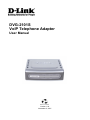
DVG-2101S VoIP Telephone Adapter User Manual Version 1.00 November 5, 2007 Table of Contents INTRODUCTION ............................................................................................................................................... 1 PACKAGE CONTENTS ....................................................................................................................................... 1 FEATURES ....................................................................................................................................................... 2 FRONT PANEL ................................................................................................................................................. 4 REAR PANEL ................................................................................................................................................... 5 HARDWARE INSTALLATION.......................................................................................................................... 6 CONFIGURATION ............................................................................................................................................ 9 SETUP............................................................................................................................................................. 13 INTERNET SETUP ........................................................................................................................................... 13 Connection Type..................................................................................................................................... 13 MAC Address Clone ............................................................................................................................... 16 Static Routing.......................................................................................................................................... 17 VOIP SETUP.................................................................................................................................................. 18 SIP Account List...................................................................................................................................... 18 Phone Book............................................................................................................................................. 19 TIME AND DATE ............................................................................................................................................. 20 ADVANCED .................................................................................................................................................... 21 VOIP SETTINGS ............................................................................................................................................. 21 Call Feature............................................................................................................................................. 21 SIP Setting .............................................................................................................................................. 23 Digit Plan................................................................................................................................................. 24 Digit Map ................................................................................................................................................. 27 Dial Prefix................................................................................................................................................ 29 Codec...................................................................................................................................................... 30 Phone Setting.......................................................................................................................................... 31 DNS ............................................................................................................................................................. 32 DYNAMIC DNS .............................................................................................................................................. 33 QOS ............................................................................................................................................................. 34 VPN ............................................................................................................................................................. 35 Dialing out Settings ................................................................................................................................. 35 MAINTENANCE .............................................................................................................................................. 37 SYSTEM ........................................................................................................................................................ 37 Configuration........................................................................................................................................... 37 Auto Provision ......................................................................................................................................... 38 SNMP (for SNMP model only) ................................................................................................................ 39 Log Setting .............................................................................................................................................. 40 FIRMWARE UPDATE ....................................................................................................................................... 41 ACCESS CONTROL ......................................................................................................................................... 42 PING TEST .................................................................................................................................................... 43 STATUS .......................................................................................................................................................... 44 DEVICE INFORMATION .................................................................................................................................... 44 VOIP STATUS ................................................................................................................................................ 45 CDR STATUS ................................................................................................................................................ 46 VPN STATUS ................................................................................................................................................ 47 NETWORK STATUS......................................................................................................................................... 48 SYSTEM LOG ................................................................................................................................................. 49 HELP ............................................................................................................................................................... 50 HELP MENU................................................................................................................................................... 50 CONFIGURATION THROUGH IVR ................................................................................................................ 51 FREQUENTLY ASKED QUESTIONS ............................................................................................................ 52 TECHNICAL SPECIFICATIONS..................................................................................................................... 55 Introduction DVG-2101S User Manual Introduction The D-LINK DVG-2101S VoIP Telephone Adapter links conventional telephony devices such as analog phones or fax machines to IP networks. The DVG2101S includes one Ethernet port and one RJ-11 telephone jack that provide voice communication over the IP network. The Ethernet port is for a DSL/Cable Modem or other WAN (Wide Area Network) devices. It can be configured and monitored using a web browser. This VoIP Telephone Adapter can reduce or eliminate long distance or interoffice phone charges by routing calls over the Internet or any IP network. Corporations can also enjoy the benefits of network consolidation and reduction of leased lines by relying on the Internet service providers to deliver toll-quality voice communications over the IP networks. Package Contents z z z z z 1 x DVG-2101S VoIP Telephone Adapter 1 x CAT5 Ethernet Cable (Blue) 1 x RJ-11 Phone Cable (Gray) 1 x 12V/1.5A AC/DC Adapter 1 x CD-ROM 1 DVG-2101S User Manual Introduction Features z WAN support One 10/100Mbps auto-MDI/MDIX Ethernet port WAN Type: Static IP, Dynamic IP, and PPPoE MAC Address Clone NAT Traversal: Outbound Proxy, STUN Dynamic DNS support: DlinkDdns, DynDns VLAN ID Tag QoS: IP Precedence NTP z Management Web-base, Telnet, and telephone keypad configuration (dial prefix) Built-in Ping Tool Remote firmware upgrade via TFTP, HTTP, HTTPS, and FTP Multi-function reset button: IVR, reset , restore the factory default Password Protected controlled Admin and User Access Authority Auto Provisioning: y Web Browser Administration and Configuration via Integral Web Server Telephone Key y Pad Configuration with Interactive Voice Prompts, Automated Provisioning & Upgrade via HTTPS, HTTP, TFTP,FTP IVR SNMP V1/V2C TR-069 (include TR-104) (optional) z Call In & Call Out Voice over IP Call IP Address Calling Three Way IP to IP Conference Call z Call Features Call Forwarding: No Answer/Busy/Unconditional Call Transfer: Unattended/Attended Call Waiting / Call Pickup / Call Hold / Call Back On Busy / Call Return / Three Way Calling (Media Server required) MWI based on LED & Tone DND (Do Not Disturb) Warm Line Hot Line Selective/Anonymous Call Rejection Music On Hold Caller ID (Type I and Type II) Caller ID Blocking Speed Dialing, Repeat Dialing Consultation Hold z Voice Functionality SIPv2 (RFC3261) compliance SIP Proxy Redundancy: Dynamic via DNS SRV, A Records Reregistration with Primary SIP Proxy Server. SIP Extension: Session Timer, Proxy-Require MD5 Authentication for SIP 2 Introduction DVG-2101S User Manual SIP NAT Keep Alive Time VPN Flash Hook Timer Adaptive jitter buffer Programmable gain control In-band DTMF Out-of-band DTMF relay: RFC2833/ SIP info DTMF Termination Impedance: 600/900& complex Impedance Failover SIP Proxy server registrations T.30 FAX pass through, T.38 real time FAX relay Caller ID: DTMF, FSK-Bellcore, FSK-ETSI detection and generation by country select Telephone book Voice Codec Feature: G.711 u-law/a-law, G.723.1/iLBC (optional), G.726, G.729.A/B VAD (Voice Activity Detection) CNG (Comfort Noise Generation) G.165/G.168 Echo Cancellation Silence Suppression & Detection 3 DVG-2101S User Manual Introduction Front Panel Power LED This LED will light solid when the device finishes a self-test and booting up. This LED will flash during device self-test and booting and light off if the self-test fails. Phone LED This LED will light solid when the telephone is off-hook. A fast blinking LED indicates an incoming call and a slow blinking LED indicates a message is waiting. This LED will light off if the phone connected to the phone port is on-hook. Register LED This LED will light solid if the phone account registers successfully. This LED will flash during registering and light off if registering fails. Provision LED This LED will light solid if the device provisions successfully. This LED will flash during provisioning and light off if provisioning fails. 4 WAN LED This LED will light solid when a connection is established and blink to indicate activity. If this LED does not light up when a cable is connected, verify the cable connections and make sure your devices are powered on. Introduction DVG-2101S User Manual Rear Panel Reset Button Use a paper clip to: 1. Press 1-2 seconds to enable IVR. 2. Press 4-6 seconds to reset this unit. 3. Press 8-10 seconds to restore this unit’s factory default settings. Phone Port Connects to your phone using a standard phone cable (RJ-11). Power Receptor Connects to the provided power adapter. WAN Port Connects to your broadband modem using an Ethernet cable. 5 DVG-2101S User Manual Hardware Installation Hardware Installation Connecting the DVG-2101S Directly to a Modem If your computer connects directly to a DSL or Cable modem and does not connect to a router, follow the steps below to install your DVG-2101S. Note: This is the most common setup configuration for the DVG-2101S. If you do not require the use of more than one LAN port, you do not need an additional router. 1. Turn off your computer. 2. Disconnect the power to your Cable/DSL modem (unplug or turn off the power switch). 3. Unpack the Ethernet cable (blue) that comes with DVG-2101S. Attach one end of the Ethernet cable (blue) provided in this package to a LAN or Ethernet port on your Cable/DSL modem. If there are no Ethernet ports available on your modem, you should include a router in your network setup (see diagram on the next page). 4. Attach the other end of the provided Ethernet cable to the WAN port of the DVG-2101S. 5. Attach one end of the provided phone cable (gray) to a standard analog telephone. 6. Attach the other end of the phone cable to the PHONE port on the rear panel of the DVG-2101S. 7. Reconnect the power to the Cable/DSL Modem (plug in or turn on the power switch). 8. Unpack the 12V DC power adapter that comes with the DVG-2101S. Connect the power adapter to the power connecter on the DVG-2101S. 9. Connect the other end of the power adapter to an available electrical outlet (wall socket or surge protector). 10. Restart your PC. 6 Hardware Installation DVG-2101S User Manual Connecting the DVG-2101S Behind a Router If you wish to connect your DVG-2101S behind a router, follow the steps below. After the steps are completed, your setup should look similar to the diagram below. 1. Turn off your computer. 2. Disconnect the power to the Cable/DSL modem (unplug the modem or turn off the power switch). 3. Disconnect the power to your existing router (unplug the router or turn off the power switch). 4. Unpack the Ethernet cable (blue) that came with the DVG-2101S. 5. Attach one end of this Ethernet cable to the WAN port on the rear of the DVG-2101S. 6. Attach the other end of this Ethernet cable to a LAN port on your existing router. 7. Be sure that the Ethernet cable that is plugged into the WAN port of your existing router is still plugged into your Cable/DSL Modem. 8. Unpack the phone cable (gray) that came with the DVG-2101S. Attach one end of this cable to a standard analog telephone. 9. Attach the other end of this cable to the PHONE port on the rear of the DVG-2101S. 10. Unpack the 12V DC power adapter that came with the DVG-2101S. 11. Connect the power adapter to the power connecter on the DVG-2101S. 12. Connect the other end of the power adapter to an available electrical outlet (wall socket or surge protector). 13. Reconnect the power to the Cable/DSL modem (plug in or turn on the power switch). 14. Reconnect the power to your existing router (plug in or turn on the power switch). 15. Restart your PC. 7 DVG-2101S User Manual Hardware Installation By default the unit is already configured to work behind a router. Be sure to change your computer’s IP settings to DHCP (to automatically be assigned an IP address from the DVG-2101S) regardless of what type of Internet connection you have. (Please refer to your Network Interface Card’s manual for more detailed information.) 8 Configuration DVG-2101S User Manual Configuration Prior to using your web browser for accessing the web-based configuration utility, if DHCP is not enabled on your computer, be sure to assign a static IP address to the VoIP Telephone Adapter. Use the computer that was last connected directly to your Cable/DSL modem. Right-click My Network Places > select Properties > right-click Local Area Connection > select Properties > double-click Internet Protocol (TCP/IP). Set your PC’s IP address to 192.168.1.1 and the subnet mask to 255.255.255.0. The default gateway and primary DNS server IP addresses should be the LAN IP address of the DVG-2101S (192.168.1.150). Click OK. In order to use a web browser to configure the VoIP Adapter you must make sure it has a valid Ethernet connection to a PC or LAN via its LAN port. Access the configuration utility to check the LAN port by entering the IP Address into your web browser address field. Open a web browser and type http://192.168.1.150 into the URL address box. Press the Enter or Return key. When you first log in, enter the Username admin and leave the Password blank. These may be changed later. Click the Login button. 9 DVG-2101S User Manual The Setup Wizard will guide you through the quick setup steps. Click Setup Wizard. Click Next. Step 1 You can change the login password during this step or just leave them the same as the default values. Click Next. Step 2 Select your time zone from the drop-down list. Then select a NTP time server or configure your preferred time server. Click Next. 10 Configuration Configuration DVG-2101S User Manual Step 3-1 If you selected Static IP, enter the IP address, subnet mask and gateway supplied by your ISP. Click Next. Step 3-1-1 Static IP users have to set the DNS address. Click Next. Step 3-1 If you selected Dynamic IP, you may enter the host name in the field. Click Next. 11 DVG-2101S User Manual Step 3-1 If you selected PPPoE, enter your username and password supplied by your ISP. Click Next. Step 4 Enable and configure your SIP account (phone port ) with the settings provided by your ISP/ITSP. Click Next. Step 5 Setup is finished. Click Restart to reboot the DVG-2101S. Once the adapter is finished rebooting, turn on your modem and allow up to 2 minutes to connect to your ISP. Click Restart. 12 Configuration Setup DVG-2101S User Manual Setup Internet Setup Connection Type The WAN connection type setting allows you to configure this device to establish your broadband Internet connection. Your Internet Service Provider (ISP) should provide the necessary information to you when you subscribe to the Internet access service. Dynamic IP Choose Dynamic IP if the VoIP Adapter obtains its WAN IP address from a DHCP server. Host Name Input the host name of the DHCP server. 13 DVG-2101S User Manual Setup Static IP Choose Static IP Address if the WAN IP information is provided to you by your ISP. You will need to enter in the IP address, subnet mask, gateway address, and DNS addresses provided to you by your ISP. You should enter the IP address, subnet mask, and gateway address in this page and enter the DNS addresses in the DNS page which is under the Advanced tab. IP Address Subnet Mask Gateway 14 Input the public IP Address provided by your ISP. Input your Subnet mask. (All devices in the network must have the same subnet mask.) Input the public IP address of the ISP to which you are connecting. Setup DVG-2101S User Manual PPPoE Choose PPPoE (Point-to-Point Protocol over Ethernet) if your ISP uses a PPPoE connection. Your ISP will provide you with a username and password. Most DSL users will select this option. PPPoE User Name PPPoE Password Check Password PPPoE Service Name Idle Time Out Auto Reconnect MTU Enter the PPPoE user name supplied by your ISP. Enter the PPPoE password supplied by your ISP. Retype the password entered in the previous field. Enter the PPPoE Service Name (if supplied by your ISP). Set the specific period of time, in minutes, to disconnect from the ISP when no traffic is passing through. The setting 0 minute means the VoIP adapter will never disconnect from the ISP. Check this checkbox to allow the VoIP Adapter to re-establish the connection if it is terminated by the ISP. However, if the connection is terminated under any other conditions (i.e. by Idle Timeout or manual disconnect), the VoIP Adapter will not reestablish the connection. This box is checked by default. Enter the MTU (Maximum Transmission Unit) size. MTU is the largest size packet that can be sent by the device. If the network stack of any packet is larger than the MTU value, then the packet will be fragmented before the transmission. During the PPP negotiation, the peer of the PPP connection will indicate its MTU and will accept any value up to that size. 15 DVG-2101S User Manual Setup MAC Address Clone Basically, every Ethernet interface (also called a NIC - Network Interface Card) has a MAC address. If the administrator assigns IP addresses to devices according to the authorized MAC address, or only allows devices with authorized MAC addresses to access the network, you may manually enter the MAC address here. MAC Address Check this checkbox to enable the MAC Address Clone feature. Clone MAC Address Enter the MAC address you want to use. You can find the MAC address of your PC from Start > Run. In the run box type cmd and click OK. For Windows 9x/ME, type winipcfg at the prompt and press Enter. The MAC address is listed as the "Adaptor Address". For Windows 2000/XP, type ipconfig /all at the prompt and press Enter. The MAC address is listed as the "Physical Address". 16 Setup DVG-2101S User Manual Static Routing You can specify additional information according to the network topology the VoIP Adapter is attached to in order to establish an efficient networking environment. Click Add button to configure static routing settings. Network Destination Netmask Gateway Enter in the IP address of the specified network that you want to access using the static route. Enter in the subnet mask for the specified network. Enter in the gateway IP address of the specified network. 17 DVG-2101S User Manual Setup VoIP Setup The VoIP (Voice over Internet Protocol) Adapter can be configured to handle voice communication over the Internet. The screen shown below, along with the SIP account list and phone book pages are used to configure the basic settings to allow you to communicate with the devices that will send and receive telephone calls over the Internet. SIP Account List The VoIP Adapter allows you to make calls through the Internet or PSTN. You need to configure the SIP account before you can make a VoIP phone call. Display Name Enter your display name. Every outgoing call will carry this name to the receiver and it should appear on the Caller-ID. Enter your SIP account username. The username is the part User Name that comes before the “@” symbol. A username can be letters like in an e-mail address (e.g. [email protected]) or numbers like a telephone number (e.g. [email protected]). Authorization Enter the authorization name to authenticate your SIP account. This is usually the same to your SIP account’s user name. Name Enter the password to authenticate your SIP account. Password Proxy Server Enter the SIP proxy server’s IP address and port number in this field (e.g. 192.168.0.253:5060). Enter the outbound proxy server IP address and port number in Outbound Proxy Server this field (e.g. 192.168.0.1:5060). Expire Time Enter the amount of time for the dial tone when the phone has been lifted off the hook. At the end of this time period, if no numbers have been dialed, the device will start playing the busy tone. Check the checkbox to activate MWI (Message Waiting MWI Indication) if the SIP server supports this service. 18 Setup DVG-2101S User Manual Phone Book This page allows you to add and edit your frequently used VoIP phone numbers in the phone book. It is also required if you want to make peer-to-peer calls. In peer-to-peer calls, you call another VoIP device directly without going through a SIP server. Click the Add button to edit the phone book. Phone Number Display Name Distinctive Ring SIP URL Enter the phone number of your contact. Enter a name to display on telephone set’s LCD screen when there is an incoming call from your contact. Select a distinctive ring type from the drop-down list to classify the incoming calls into different categories such as family, friends, or colleagues. Enter the SIP URL of your contact. The format of a SIP URL is similar to an e-mail account. The format should be [email protected]. 19 DVG-2101S User Manual Setup Time and Date The VoIP Adapter allows you to maintain the system clock via the Internet. You must first select your time zone from the drop-down list, then select a predefined NTP (Network Time Protocol) time server from the drop-down list, or specify the IP address of your preferred NTP time server on the Internet manually. Synchronizing with a time server ensures the time-based client filtering features and system log entries are based on the correct localized time. Check this checkbox and then select the preferred time Automatically synchronize with server(s) from the drop-down NTP Time Server list. Internet Select the time zone where you reside from the drop-down Time Zone list. Enable Daylight Check this checkbox if your location uses daylight saving. Then select the daylight saving offset from the drop-down Saving list. Daylight Saving Select the start and end date for daylight saving to take effect from the drop-down list. Dates 20 Advanced DVG-2101S User Manual Advanced VoIP Settings This VoIP section allows you to configure advanced settings for your VoIP connections. Call Feature This page allows you to configure advanced features for your SIP account. Forward Always Forward Busy Forward No Answer Check the checkbox and enter the phone number to forward all incoming calls to, regardless of any other conditions. Check the checkbox and enter the phone number to forward all incoming calls to, if the phone port is busy. Check the checkbox and enter the phone number to forward all incoming calls to, if the call is not answered. You must also enter the number (in seconds) that the VoIP Adapter should wait for you to answer an incoming call before it considers the call unanswered. 21 DVG-2101S User Manual Advanced Warm Line* Check the checkbox and enter a specific number to be dialed automatically by the VoIP Adapter when the user goes off-hook on the line and does not input any digits after a configurable timeout has elapsed. For example, this feature can be used for emergency or operator dialing if you do not input any dialing information after a certain time. Check the checkbox and enter a specific number to be dialed Hot Line* right away automatically by the VoIP Adapter when the user goes off-hook on the line. Check this checkbox to reject incoming calls as busy or divert Do Not incoming calls to a voice mail server when configured to do so. Disturb Call Waiting Check the checkbox to receive a second call when a call is already ongoing on the same phone port. Consultation Check the checkbox to let you place a call on hold, and then call another party to consult privately, and afterward, return to the Hold original call. Conference Check the checkbox to enable making conference calls. Check the checkbox to enable call back on busy when the Call Back number you dialed is busy. On Busy Check the checkbox to enable PSTN fail over relay when the PSTN Fail Over Relay Internet connection is not available. *You can only activate either Warm Line or Hot Line. If you check both of them, Hot Line’s priority is always prior to Warm Line. Examples of Making a Conference Call Scenario 1: 1. The first person dials the second person and asks the second person to wait. 2. The first person presses Flash then calls the third person (and keeps the second person on hold). 3. The third person answers the call. The first person dials *61 and then presses Flash to start the conference call. Scenario 2: 1. The first person dials the second person and the second person answers the call. 2. The third person dials the first person (call waiting) and the first person presses Flash to pick up the second call and talk to the third person. 3. The first person dials *61 and then presses Flash to start the conference call. Note: The availability of conference calls varies depending on your VoIP network. Please check with your ITSP for this service. 22 Advanced DVG-2101S User Manual SIP Setting This page allows you to configure the settings related to the SIP service provider. You need to configure your VoIP Adapter to communicate with the devices that will send and receive telephone calls over the Internet. If you are behind a NAT modem or router, you may have to use a STUN server. Signaling Port RTP Start RTP End STUN Server Address NAT Keep Alive Time Rport T.38 Fax Protocol Enter the signaling port to send and receive the SIP message for building a session. The default value is 5060 and this must match with the peer Registrar when making VoIP calls. Specifies the start port for the RTP stream. The default value is 40000. Specifies the end port for the RTP stream. The default value is 50000. Enable or disable the STUN server feature. Enter the STUN server IP address if you enabled the STUN server feature. Check the checkbox and enter the time period for the NAT to keep alive. Check this checkbox to use rport. Rport, or symmetric signaling, is critical for operations behind some classifications of NATs. If enabled, the SIP stack will send outbound SIP messages on the same port that it listens on. Unless you are familiar with single SIP port, it is better to use rport. Check the checkbox if the remote end also supports FAX function. 23 DVG-2101S User Manual Advanced P_Assert Check the checkbox to enable P_Assert to hide the client name when sending messages to the SIP proxy server. Check the checkbox to enable E.164 ENUM (Number Mapping) feature. E.164 is a mechanism to transform an E.164 number into a list of URIs (Uniform Resource Identifiers) so that the IP users and available services can be identified by a public telephone number. Check the checkbox to enable this function. If there is no response, the connecting call will be closed automatically after the time limit that you set in this field. Check the checkbox to reject all anonymous calls. E.164 ENUM Session Timer Anonymous Call Rejection Check this checkbox to use DTMF (Dual Tone Multi-Frequency) DTMF Info to send out the Caller ID. Type Digit Plan This page enables you to set up rules for the digit waiting time and the digit plan. A digit plan is also known as a dial plan. A digit plan is a string of characters that governs the way the VoIP Adapter processes inputs received from the telephone keypad. This includes country codes, access codes, area codes, and all combinations of digits dialed. Digit plans must comply with the telephone networks to which they connect. First Digit Waiting Time Interval Digit Waiting Time Digit Plan 24 Enter the first digit waiting time before the connection is canceled by the VoIP Adapter. Enter the interval waiting time between two digits before the connection is canceled by the VoIP Adapter. Enter the strings for the digit plan. Advanced DVG-2101S User Manual Digit Plan Syntex To specify a Enter the following Result Digit 0 1 2 3 4 5 6 7 8 9 * Identifies a specific digit (do not use #) Range [digit-digit] Identifies any digit dialed that is included in the range Range [digit-digit, digit] Specifies a range as a comma separated list Wildcard x x matches any single digit that is dialed Wildcard . . matches an arbitrary number of digits Time T Indicates that an additional time out period of 4 seconds should take place before automatic dialing starts For example, let’s look at the following digit plan: <:1780>[2-4]xxxxxx|*xx|<911:17804213333>|011[2-9]x.T|1[2-9]xx[2-9]xxxxxx|1900xxxxxxx! A digit plan is the combination of one or more dialing rules. The above digit plan includes six dialing rules and is separated by five “|” characters. The VoIP Adapter interprets the digit plan (strings) in order from left to right. That is, if you dial a set of numbers that fits to more than one section of the digit plan, the VoIP Adapter will use the first numerical sequence that fits to process your inputs. Component Description <> A pair of < > brackets is used to enclose digit and character for special usage such as add prefix to the following digit(s) or replace the digits you dialed. For example, <:111>*123 means that when you press 123 on the keypad, the VoIP Adapter will send out 111*123. <*123:#911> means when you dial *123, the VoIP Adapter will send out #911. : The “:” means replace any digits within the < > brackets before the “:” with the digits written after the “:” For example: <:1780> means the system prefixes all numbers that match with the remainder of the dial plan string with “1780”. <911:17804213333> means the system will send out the call with 17804213333 whenever you dial 911. If you live in Australia and your VoIP provider resides in North America, your may change this dial plan to <000:011612131444>. [] A pair of [ ] brackets is used to enclose one digit (the digits on telephone keypad *, # and 0-9). For example, [*#2-9] means the digit can be either *, #, 2, 3, 4, 5, 6, 7, 8 or 9. [*1-3579] mean the digit can be either *, 1, 2, 3, 5, 7 or 9. x The x represents any digit from 0 to 9. x means one 0-9 digit, xx means two 0-9 digits and xxx means three 0-9 digits, etc. For example, [2-4]xxxxxx means you are allow to dial either 2,3 or 4 followed by any six digits from 0 to 9. | The “|” in a digit plan is merely used to separate the different dialing rules. 25 DVG-2101S User Manual * . T ! Advanced The “*” represents the * (star key) on your telephone keypad. For example, *xx means press * key followed by any two digits from 0-9, such as *69 or *55. The “.” (dot) means repeat the previously listed digit zero or more times. For example, x. means zero or more digits and xx. means at least one or more digits. The “T” represents that an additional timeout period should take place before automatic send out the dialing. The “!” in a digit plan means the digit or number is restricted. For example, 11[0, 2, 4, 9]! means the system will block the numbers 110, 112, 114 and 119. 00886! means that the dial out number beginning with 00886 is restricted. Note that the “!” can only be placed at the end of a dialing rule. The VoIP Adapter processes call features and the digit plan in the following sequence: Digits Input* IVR Phone Book Digit Map Digit Plan Send Out * Including keypad dialing, hotline, warm line, etc. If you configure the dialing rules or behaviors in the VoIP Adapter as: Rule 1: in dial prefix settings, set *666 for IVR accessing Rule 2: in phone book settings, set *666 to map to the URL: [email protected] Rule 3: in the digit map, set *666 to be replaced by 911 Rule 4: in the digit plan, set *666 to be accepted and 911 to be restricted When there are rules 1 to 4 in the system, pressing *666 will enter the VoIP Adapter’s IVR mode. When there are rules 2 to 4 in the system, pressing *666 will make a VoIP call to [email protected] When rule 3 and rule 4 are in the system, pressing *666 will be replaced with 911 by the VoIP Adapter, but this number will not be sent out. When there is only rule 4 in the system, pressing *666 will immediately send the dialing to the proxy or UA. 26 Advanced DVG-2101S User Manual When you dial *666: Scenario Rule Combination The VoIP Adapter will do… 1 Rule1 + Rule2 + Rule3 + Rule4 = Enter the VoIP Adapter’s IVR mode 2 Rule2 + Rule3 + Rule4 = Address a call to [email protected] 3 Rule3 + Rule4 = Replace the input with 911, but this number will not be sent out 4 Rule4 = Immediately send the dialing to the proxy or UA If the dialed numbers or characters do not match to the digit plan, you will probably hear a busy tone from the telephone handset. Digit Map This page enables you to set up rules for modifying dialed numbers, or varying the dialing behavior depending on the number called. The digit map specifies how to interpret digit sequences dialed by the user, and how to convert those sequences into an outbound dial string. Click the Add button to add a digit map. 27 DVG-2101S User Manual Prefix Mode OP Number Min Len Max Len Interface Advanced The prefix specifies a series of digit sequences. When you dial a series of digits, each sequence in the prefix is tested as a possible match. The matching sequences form a set of candidate digit sequences. The phone number set here is used to add, strip, or replace the OP number. None: No action. Add: When you choose this mode, the OP number will be added with the prefix number for calling out through the specific phone interface. Replace: If you select this mode, the OP number will be replaced by the prefix number for calling out through the specific phone interface. Delete: If you select this mode, the OP number will be deleted by the prefix number for calling out through the specific phone interface. Restrict: If you select this mode, the OP number will be restricted by the prefix number for calling out through the specific phone interface. The front number you type here is the first part of the account number that you want to execute a special function (according to the chosen mode) by using the prefix (number). If you selected the mode "Add", “Replace”, or "Delete", the OP number will be applied in this rule. Set the minimal length of the dial number for applying the prefix number settings. Set the maximum length of the dial number for applying the prefix number settings. You can apply the prefix number settings to the PHONE port (Phone 1). Example: z The first rule accepts calls using 03 as the prefix number. For example, if you dial "038993765", it matches this rule and the VoIP Adapter will make the phone call "886038993765". z The second rule accepts calls using 06 as the prefix number. For example, if you dial "065991234", it matches this rule, and its length (not including the length of the prefix) is 7, between 6 (Min Len) and 8 (Max Len), therefore the VoIP Adapter will make the phone call "065991234". z The third rule accepts calls using 9 as the prefix number. For example, if you dial "93652400", it matches the third rule and the VoIP Adapter will make a phone call "08003652400". 28 Advanced DVG-2101S User Manual Dial Prefix This page allows you to configure your dialing policy. You can change the default dial prefix settings to fit you dialing behavior. 29 DVG-2101S User Manual Advanced Codec The codec used for each call will be negotiated with the peer party before each session, and therefore many codecs will not be included in your default configuration. The default codec is G.729A, it occupies little bandwidth while maintaining good voice quality. If your upstream speed is only 64Kbps, using G.711_A codec is not recommended. It is better to have at least 256Kbps upstream if you would like to use G.711_A. There are five priorities for you to configure the codec priority in the order you preferred. Priority 1 means the first priority and priority 5 means the last. Select the codec type from the drop-down list. Codec Packetization Select the length of the digital voice segment that each packet holds. The default is 20 millisecond packets. Selecting 10 Time millisecond packets enhances the voice quality, as less information is lost due to packet loss, but doubles the load on the network traffic. Select the method of DTMF tone generation from the dropDTMF down list. Priority 30 Advanced DVG-2101S User Manual Phone Setting This page allows you to enable VAD (Voice Activity Detection), CNG (Comfortable Noise Generation), and Echo Cancellation. You can also specify the Receive/Send Gain as well as select the Telephony Tone and Caller ID type. The VoIP Telephone Adapter provides default ring-tone parameters configured for various countries. Voice Activity The VAD (Voice Activity Detection) feature allows the VoIP Adapter to stop transmitting when you are not speaking. This Detection reduces the bandwidth the VoIP Adapter uses. Comfortable The CNG (Comfortable Noise Generation) feature allows the VoIP Adapter to generate comfortable background noise to Noise indicate that you are still on the line. Generation Enable the Echo Cancellation feature to eliminate the echo Echo Cancellation caused by the sound of your voice reverberating in the telephone transmitter while you talk. Receive Gain Enter the receive gain value. Enter the send gain value. Send Gain Select the telephony tone type from the drop-down list Telephony according to your region. Tone Select the caller ID type from the drop-down list according to Caller ID your region. 31 DVG-2101S User Manual Advanced DNS The DNS (Domain Name System) feature allows you to set the configuration of the DNS proxy. DNS Server Configuration Primary DNS Address Secondary DNS Address 32 Select to obtain DNS server address automatically or specify the DNS server(s) if you are provided DNS information by your ISP. Enter the primary DNS IP address provided by your ISP. Enter the secondary DNS IP address provided by your ISP. This is an optional DNS Address entry to be used if the primary DNS server fails. Advanced DVG-2101S User Manual Dynamic DNS The Dynamic DNS service allows you to bind the device's public IP address to a static hostname, allowing your computer to be more easily accessed from various locations on the Internet. Most broadband Internet Service Providers assign dynamic (changing) IP addresses. Using a DDNS service provider, your friends can enter in your domain name to connect to your server no matter what your IP address is. When this feature is enabled, this device will automatically update your DDNS records whenever your IP address changes. Server Address Enter your DDNS server’s IP address provided by your DDNS service provider. You can also select a pre-defined DDNS service provider from the drop-down list. Enter the host/domain name that you registered with your Host Name DDNS service provider. Enter the username or key for your DDNS account. Username or Key Password or Key Enter the password or key for your DDNS account. Verify Password Re-enter the password or key for your DDNS account. or Key Enter the DDNS timeout period in hour(s). Timeout This field shows the DDNS connection status as connected Status or disconnected. 33 DVG-2101S User Manual Advanced QoS The QoS (Quality of Service) feature allows you to classify traffic by its priority and mark it with a Differentiated Services (DiffServ) flag. VLAN ID Priority (Voice/Data) Specify the VLAN ID from 0 to 4095. Indicate the priority of voice and data separately. The higher the value, the higher the priority. If you configure data and voice with the same value, it means they have the same priority. You can set the voice priority to the highest value 7 in order to ensure the best voice quality. 34 Advanced DVG-2101S User Manual VPN A Virtual Private Network (VPN) is the extension of a private network that encompasses links across shared or public networks like the Internet. In short, using VPN technology, you can send data between two computers across a shared or public network in a manner that emulates the properties of a point-topoint private link. Dialing out Settings This page allows you to configure the dialing out setting to be IPSec (Internet Protocol Security), PPTP (Point-to-Point Tunneling Protocol), or L2TP (Layer 2 Tunneling Protocol) and its local IP and remote IP(s). Click the Add button to create a profile for the VPN connection. 35 DVG-2101S User Manual Advanced Enter an account name for the connection. You can configure up to four accounts for this device. Select the VPN type to be IPSec, PPTP, or L2TP from the dropdown list. User Name Enter the user name for VPN connection. Password Enter the password for VPN connection. Enter the server IP for VPN connection and/or check the Server IP checkbox to use the remote VPN gateway as the default gateway. Enter the remote LAN IP for the VPN connection. Remote LAN IP Enter the remote LAN mask for the VPN connection. Remote LAN Mask Account Name Type 36 Maintenance DVG-2101S User Manual Maintenance System Configuration These configuration tools help you reboot, backup, restore settings, or reset the VoIP Adapter to its factory default settings. Reboot Backup Settings Update Settings Restore Default Settings This feature allows you to reboot the device while still keeping its current settings. This feature allows you to save the device's current settings as a file on your PC. This feature allows you to update the device’s current configuration with your previously saved files. This feature allows you to force the device to perform a power reset and restore the original factory default settings. 37 DVG-2101S User Manual Maintenance Auto Provision This page allows you to automatically update your VoIP Adapter’s configuration by using a TFTP, FTP, HTTP, or HTTPS server located on the Internet. If you have to access such services, you will need to know the IP address of the provisioning server. Select your provision criteria to be Only Power Up, Interval, or Auto Provision Disable. Protocol Indicate the provision protocol supplied by your ISP from the dropdown list. Enter the IP address supplied by your ISP for the device to IP provision. Enter the port number supplied by your ISP for the device to Port provision. The default port number is 69. Provision Enter the number of times to provision. Times Enter the period to provision if you set your provision criteria as Period Interval. Enter the file name supplied by your ISP for the device to provision. File 38 Maintenance DVG-2101S User Manual SNMP (for SNMP model only) SNMP (Simple Network Management Protocol) is a protocol allowing network administrators to obtain information and even configure various network devices remotely. A computer attached to the network is called a Network Management Station (NMS). The access rights to the agent are controlled by community strings. To communicate with the VoIP Adapter, the NMS must first submit a valid community string for authentication. This page allows you to configure basic access control, using passwords called community (strings). SNMP Version Read Community Write Community Trap Receive Server Trap Community Select the SNMP version from the drop-down list. The VoIP Adapter supports both v1 and v2 protocols. Enter the read community string for authorizing read-only rights. The default string is public. Enter the write community string for authorizing read-and-write rights. The default string is private. Enter the trap receive server’s IP address for the traps to be sent to this address when errors or specific events occur on the network. Enter the trap community string for authorizing trap management rights. 39 DVG-2101S User Manual Maintenance Log Setting This page allows you to configure settings to upload logs to a TFTP server and/or download logs to your local drive. TFTP Server IP Update Interval Max File Size Log File Type 40 Enter the IP address of a TFTP server. Enter the update interval in day(s). Enter the maximum file size that can be accepted. Select the log file type, either System Log or Network Statistics, from the drop-down list to download logs. Maintenance DVG-2101S User Manual Firmware Update This tool allows you to upgrade this device's firmware locally. This device is also capable of being managed remotely by the service provider. Note: Please contact your Internet Service Provider prior to upgrading your firmware. The update process takes several minutes to complete, and your VoIP Adapter will reboot. Please DO NOT power off your device before the update is complete. Firmware Enter the path and name, or click the Browse button to locate the File Name upgrade file then click the Update Firmware button. You will be prompted to confirm the upgrade to complete the process. 41 DVG-2101S User Manual Maintenance Access Control Access to your VoIP Adapter is controlled through two user accounts: admin and user. The username “admin” has unrestricted access to change and view the settings of the VoIP Adapter. The username “user” can access the VoIP Adapter, view configuration settings and statistics, and update the VoIP Adapter's software. By default, all passwords are intentionally left as blank. You can change the administrator and common user’s passwords respectively in this page. The VoIP Adapter will log you out automatically after the web interface is idle for a period of time. The default idle timeout value is 300 seconds. You can change the time period if necessary. Enter the administrator’s current login password. Admin Current Password Enter a new password for the administrator to login. Admin New Password Confirm Password Re-enter the new password for verification. Enter the session timeout duration (in seconds). The Session Time system will disconnect the access rights of the administrator when the session time is up. Enter a new password for the user to login. User New Password Confirm Password Re-enter the new password for verification. 42 Maintenance DVG-2101S User Manual Ping Test The VoIP Adapter allows you to perform a ping test. This feature helps you to diagnose connection problems. If you can ping an IP on the WAN side successfully, you should be able to access the Internet. IP/Domain Enter the IP/Domain you want to ping in the field below and then click the Ping button. 43 DVG-2101S User Manual Status Status Device Information You can use the Device Info screen to view the connection status for the VoIP Adapter's WAN/LAN interfaces, current firmware, and other related information. 44 Status DVG-2101S User Manual VoIP Status You can use the VoIP Status screen to view the phone port status. 45 DVG-2101S User Manual Status CDR Status You can use the CDR (Call Detail Record) Status screen to view the call history records of incoming and outgoing calls. It stores up to 100 records. 46 Status DVG-2101S User Manual VPN Status You can use the VPN Status screen to view the VPN connection status. 47 DVG-2101S User Manual Status Network Status You can use the Network Status screen to view the routing table, VoIP and network statistics to observe the current network conditions. 48 Status DVG-2101S User Manual System Log You can view all the records of events that have occurred on the VoIP Adapter. 49 DVG-2101S User Manual Help Help Help Menu This help menu provides some information to help you know more details about the VoIP Adapter. Select the item which you want to view to display the description. 50 Configuration through IVR DVG-2101S User Manual Configuration through IVR The VoIP Adapter provides a convenient IVR (Interactive Voice Response) function to help you query and configure the basic settings of the VoIP Adapter with a phone and without turning on a PC. To access IVR mode, plug a phone into the VoIP Adapter and then pick up the handset and press * (star) 666 # (pound). You will hear voice instructions through the handset. Follow the system’s instructions to set up or query the VoIP Adapter’s settings. To exit IVR mode, simply hang up the phone. The IVR function only supports DHCP and Static mode configuration, other connection types need to be done via the web configuration interface. If you pick up the handset and can not hear a tone or press *666# without IVR response, please press the Reset button for 1-2 seconds and try again. Please refer to the Rear Panel diagram on page 5 of this manual for the Reset button location. 51 DVG-2101S User Manual Frequently Asked Questions Frequently Asked Questions Q: Why can’t I access the web-based configuration utility? A: When entering the IP address of the VoIP Adapter (192.168.1.150), you are not connecting to a website on the Internet and don’t have to be connected to the Internet. The device has the utility built into a ROM chip in the device itself. Your computer must be on the same IP subnet to connect to the web-based utility. z Make sure you have an updated Java-enabled web browser. We recommend the following: y Internet Explorer 6.0 or higher y Netscape 8 or higher y Mozilla 1.7.12 (5.0) or higher y Opera 8.5 or higher y Safari 1.2 or higher (with Java 1.3.1 or higher) y Camino 0.8.4 or higher y Firefox 1.5 or higher z Verify physical connectivity by checking for solid link lights on the device. If you do not get a solid link light, try using a different cable or connect to a different port on the device if possible. If the computer is turned off, the link light may not be on. z Disable any Internet security software running on the computer. Software firewalls such as Zone Alarm, Black Ice, Sygate, Norton Personal Firewall, and Windows® XP firewall may block access to the configuration pages. z Configure your Internet settings: y Go to Start > Settings > Control Panel. Double-click the Internet Options Icon. From the Security tab, click the button to restore the settings to their defaults. y Click the Connection tab and set the dial-up option to Never Dial a Connection. Click the LAN Settings button. Make sure nothing is checked. Click OK. y Go to the Advanced tab and click the button to restore these settings to their defaults. Click OK three times. y Close your web browser (if open) and open it. z Access the web-based utility. Open your web browser and enter the IP address of your DVG-2101S in the address bar. This should open the login page for the web-based utility. z If you still cannot access the configuration, unplug the power to the VoIP Adapter for 10 seconds and plug it back in. Wait about 1 minute and try accessing the configuration. If you have multiple computers, try connecting using a different computer. 52 Frequently Asked Questions DVG-2101S User Manual Q: What can I do if I forgot my password? A: If you forgot your password, you must reset your VoIP Adapter. Unfortunately this process will change all of your settings back to the factory defaults. To reset the VoIP Adapter, locate the reset button on the rear panel of the unit. With the VoIP Adapter powered on, use a paperclip to hold the button down for 10 seconds. Release the button and the VoIP Adapter will go through its reboot process. Wait about 1 minute to access the VoIP Adapter. The default IP address is 192.168.1.150. When logging in, the username is admin and leave the password box empty. Q: How can I check if my IP address is correct for logging in? A: After you install your DVG2101S, by default, the TCP/IP settings should be set to obtain an IP address from a DHCP server automatically. To verify your IP address, please follow the steps below. Click on Start > Run. In the run box type cmd and click OK. At the prompt, type ipconfig and press Enter. This will display the IP address, subnet mask, and the default gateway of your adapter. If the address is 0.0.0.0, check your adapter installation, security settings, and the settings on your Adapter. Some firewall software programs may block a DHCP request on newly installed adapters. If you are connecting to a wireless network at a hotspot (e.g. hotel, coffee shop, airport), please contact an employee or administrator to verify their wireless network settings. 53 DVG-2101S User Manual Frequently Asked Questions Q: How can I set my computer to use a static IP address? A: If you are not using a DHCP capable gateway/router, or you need to assign a static IP address, please follow the steps below: 1. 2. 3. 4. 5. Windows® XP: Click on Start > Control Panel > Network Connections. Windows® 2000: From the desktop, right-click My Network Places > Properties. Right-click on the Local Area Connection which represents your network adapter and select Properties. Highlight Internet Protocol (TCP/IP) and click Properties. Click Use the following IP address and enter an IP address that is on the same subnet as your network or the LAN IP address on your Adapter. Example: If the Adapter’s LAN IP address is 192.168.1.150, make your IP address 192.168.1.x where x is a number between 1 and 254 but except (192.168.1.1 for example). Make sure that the number you choose is not in use on the network. Set Default Gateway the same as the LAN IP address of your DVG-2101S (192.168.1.150). Click OK twice to save your settings. Q: I get a dial tone, but when I dial any phone number I receive a busy signal. A: The unit may not have been properly configured with the correct account information in the web-based utility. 1. 2. 3. Access the web-based utility by entering the IP address: 192.168.1.150 in the Address bar. Select the Setup tab and click the SIP Account List submenu. Enter the account information provided by your VoIP service provider, including Display Name, User Name, Authentication Name, Password, Proxy Server (if applicable), Outbound Proxy Server (if applicable), etc. Q: After setting up the DVG-2101S, I cannot access the Internet. A: Make sure that the Ethernet cable from the PC is plugged into the LAN port of broadband modem or router after you finish the configuration of the DVG-2101S. Q: Can I use my DVG-2101S on a MGCP network? A: No, DVG-2101S is a SIP device and uses the SIP protocol in handling all of the telephony elements. 54 Registration DVG-2101S User Manual Technical Specifications SIP2 (RFC3261) SIP1 (RFC2543) G.711 a/u-law, G.726, G.729A/B, G.723.1 Loop-Start FXS interface DTMF tone detection/generation V.21/V.25 Modem/Fax tone detection Echo Cancellation: G.168 WAN: 10/100 Auto MDI/MDI-X Ethernet port Ethernet Ports IEEE 802.3 10BASE-T Ethernet compliant IEEE 802.3u 100BASE-TX Fast Ethernet compliant Voice service is prioritized over the data traffic Quality of Service (When unit is connected directly to the modem) Will route all standard protocols Network Protocols DHCP: Dynamic Host Configuration Protocol server and client NAT: Network Address Translation PPPoE: PPP over Ethernet Client Network Management Manage functions through a web-based configuration interface Power, Provision, Register, WAN and Phone LEDs 3.5” x 3” x 1.875” (W x D x H) Dimensions One Ethernet port (WAN) Number of Ports One FXS RJ-11 port (Phone) DC Input: 12VDC/1.5A Power Supply Operating Temperature 0-50°C Storage Temperature -10-55°C 5% - 95% non-condensing Humidity C-Tick/CUL Safety FCC Class B Emission (EMI) CE Class B Call Control Protocols Compliance Voice Compression Analog Voice Ports 55 DVG-2101S User Manual FCC EMI Statement: This equipment has been tested and found to comply with the limits for a Class B digital device, pursuant to Part 15 of the FCC Rules. These limits are designed to provide reasonable protection against harmful interference in a residential installation. This equipment generates, uses and can radiate radio frequency energy and, if not installed and used in accordance with the instructions, may cause harmful interference to radio communications. However, there is no guarantee that interference will not occur in a particular installation. If this equipment does cause harmful interference to radio or television reception, which can be determined by turning the equipment off and on, the user is encouraged to try to correct the interference by one of the following measures: - Reorient or relocate the receiving antenna. - Increase the separation between the equipment and receiver. - Connect the equipment into an outlet on a circuit different from that to which the receiver is connected. - Consult the dealer or an experienced radio/TV technician for help. FCC Caution: Any changes or modifications not expressly approved by the party responsible for compliance could void the user’s authority to operate this equipment.This device complies with Part 15 of the FCC Rules. Operation is subject to the following two conditions: (1) This device may not cause harmful interference, and (2) this device must accept any interference received, including interference that may cause undesired operation. 56