1
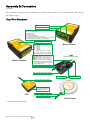
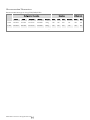
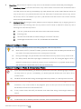
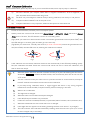
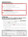
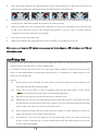
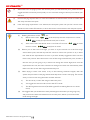
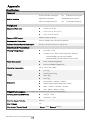
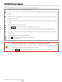
Naza-M V2 Quick Start Guide V 1.00 2013.05.02 Revision For Firmware Version V3.10 & Assistant Software Version V2.10 Thank you for purchasing this DJI product. Please strictly follow these steps to mount and connect this system on your aircraft, as well as to install the Assistant Software on your computer. Please regularly check the Naza-M V2 web page at our website www.dji-innovations.com, which is updated regularly. Product information, technical updates and manual corrections will be available on this web page. Due to unforeseen changes or product upgrades, the information contained in this manual is subject to change without notice. * This manual is only for basic assembly and configuration; you can obtain more details and advanced instructions when using the assistant software. To assure you have the latest information, please visit our website and download the latest manual and current software version. If you have any problem that you cannot solve during usage, please contact your authorized dealer. www.dji-innovations.com ©2013 DJI Innovations. All Rights Reserved. Index INDEX ...........................................................................................................................................................2 INSTRUCTION ..............................................................................................................................................3 DISCLAIMER & WARNING ..................................................................................................................................... 3 TRADEMARK ........................................................................................................................................................ 4 SYMBOL INSTRUCTION ......................................................................................................................................... 4 ASSEMBLY & CONNECTION.......................................................................................................................5 STEP1 PORT DESCRIPTION ................................................................................................................................... 5 STEP2 ASSEMBLY & CONNECTION ....................................................................................................................... 6 ASSISTANT SOFTWARE INSTALLATION AND CONFIGURATION .............................................................7 STEP1 SOFTWARE AND DRIVER INSTALLATION ON A PC ........................................................................................ 7 STEP2 CONFIGURATION BY ASSISTANT SOFTWARE ON A PC ................................................................................ 7 BASIC FLYING..............................................................................................................................................9 CONTROL MODE KNOWLEDGE ............................................................................................................................ 9 START & STOP MOTOR KNOWLEDGE ................................................................................................................... 9 STEP1 COMPASS CALIBRATION .......................................................................................................................... 11 STEP2 ASSEMBLY CHECKING LIST ...................................................................................................................... 12 STEP3 BEFORE FLIGHT ...................................................................................................................................... 12 STEP4 FLYING TEST ........................................................................................................................................... 13 ADVANCED FUNCTIONS .......................................................................................................................... 15 A1 FAILSAFE ...................................................................................................................................................... 15 A2 LOW-VOLTAGE ALERT ................................................................................................................................. 16 A3 INTELLIGENT ORIENTATION CONTROL (IOC) FLIGHT (WITH GPS MODULE) ................................................... 17 APPENDIX .................................................................................................................................................. 20 SPECIFICATIONS ................................................................................................................................................ 20 MC/PMU FIRMWARE UPGRADE ........................................................................................................................ 21 LED DESCRIPTION............................................................................................................................................. 22 INSTRUCTION OF V1 ................................................................................................................................. 23 V1 ASSEMBLY AND CONNECTION ....................................................................................................................... 23 V1 IS COMPATIBLE WITH THE PMU OF V2 ........................................................................................................... 23 V1 PORT DESCRIPTION ...................................................................................................................................... 24 V1 SPECIFICATION ............................................................................................................................................. 25 FAQ ............................................................................................................................................................ 26 ABNORMAL LED INDICATION LIST ..................................................................................................................... 26 FIX THE TBE (TOILET BOWL EFFECT) PROBLEM ................................................................................................. 26 SHOULD YOU FIND THE MULTI-ROTOR DOES NOT TRACK STRAIGHT IN FORWARD FLIGHT, ..................................... 27 ©2013 DJI Innovations. All Rights Reserved. Instruction Disclaimer & Warning Please read this disclaimer carefully before using the product. By using this product, you hereby agree to this disclaimer and signify that you have read them fully. THIS PRODUCT IS NOT SUITABLE FOR PEOPLE UNDER THE AGE OF 18. Naza-M V2 is an autopilot system designed for serious multi-rotor enthusiasts providing excellent self-leveling and altitude holding, which completely takes the stress out of flying RC multi-rotors for both professional and hobby applications. Despite the system having a built-in autopilot system and our efforts in making the operation of the controller as safe as possible when the main power battery is connected, we strongly recommend users to remove all propellers when calibrating and setting parameters. Make sure all connections are good, and keep children and animals away during firmware upgrade, system calibration and parameter setup. DJI Innovations accepts no liability for damage(s) or injuries incurred directly or indirectly from the use of this product in the following conditions: 1. Damage(s) or injuries incurred when users are drunk, taking drugs, drug anesthesia, dizziness, fatigue, nausea and any other conditions no matter physically or mentally that could impair your ability. 2. Damage(s) or injuries caused by subjective intentional operations. Any mental damage compensation caused by accident. 3. Failure to follow the guidance of the manual to assemble or operate. 4. Malfunctions caused by refit or replacement with non-DJI accessories and parts. 5. Damage(s) or injuries caused by using third party products or fake DJI products. 6. Damage(s) or injuries caused by mis-operation or subjective mis-judgment. 7. Damage(s) or injuries caused by mechanical failures due to erosion, aging. 8. Damage(s) or injuries caused by continued flying after low voltage protection alarm is triggered. 9. Damage(s) or injuries caused by knowingly flying the aircraft in abnormal condition (such as water, oil, soil, sand and other unknown material ingress into the aircraft or the assembly is not completed, the main components have obvious faults, obvious defect or missing accessories). 10. Damage(s) or injuries caused by flying in the following situations such as the aircraft in magnetic interference area, radio interference area, government regulated no-fly zones or the pilot is in backlight, blocked, fuzzy sight, and poor eyesight is not suitable for operating and other conditions not suitable for operating. 11. Damage(s) or injuries caused by using in bad weather, such as a rainy day or windy (more than moderate breeze), snow, hail, lightning, tornadoes, hurricanes etc. 12. Damage(s) or injuries caused when the aircraft is in the following situations: collision, fire, explosion, floods, tsunamis, subsidence, ice trapped, avalanche, debris flow, landslide, earthquake, etc. 13. Damage(s) or injuries caused by infringement such as any data, audio or video material recorded by the use of aircraft. 14. Damage(s) or injuries caused by the misuse of the battery, protection circuit, RC model and battery chargers. 15. Other losses that are not covered by the scope of DJI Innovations liability. ©2013 DJI Innovations. All Rights Reserved. Trademark DJI and Naza-M are registered trademarks of DJI Innovations. Names of product, brand, etc., appearing in this manual are trademarks or registered trademarks of their respective owner companies. This product and manual are copyrighted by DJI Innovations with all rights reserved. No part of this product or manual shall be reproduced in any form without the prior written consent or authorization of DJI Innovations. No patent liability is assumed with respect to the use of the product or information contained herein. Symbol Instruction Forbidden(Important) ©2013 DJI Innovations. All Rights Reserved. Cautions Tip Reference Assembly & Connection In the Box: Main controller X1, PMU X1, GPS X1, GPS Bracket X1, LED X1, Servo Cable X8, Micro-USB Cable X1, CAN Cable X1, 3M Adhesive Tape. Step1 Port Description EXP:Connect to PMU module LED:Connect to LED module A: For roll control (left/right) E: For pitch control (front/back) T: For throttle control R: For rudder control U: For Control Model Switch X1: For gimbal pitch control / For gain tuning X2: For D-Bus(S-Bus compatible) / For gain tuning / For IOC switch X3: For voltage monitor(Connect to PMU V-SEN port) Pointing to the aircraft nose direction M1: To #1 ESC(*) M2: To #2 ESC M3: To #3 ESC M4: To #4 ESC M5: To #5 ESC M6: To #6 ESC F1: To gimbal roll servo or To #7 ESC F2: To gimbal pitch servo or To #8 ESC NAZA output is 400Hz refresh frequency Main Controller V-SEN: Connect to Main Controller X3Port Important: the continuous output of the PMU is 3A@5V, and the maximum instant current is 7.5A. If PMU cannot afford the working current for your servos, please use an independent power supply; otherwise, it may cause the PMU safeguard and lead to the main controller reboot。 Main Controller PMU (Power Management Unit) 2S~6S: Powered by 2S~6S LiPo(7.2V~26.0V) GPS: Connect to GPS/Compass module Extended CAN port EXP: Connect to Main Controller EXP port Connect to Main Controller LED port Micro-USB: PC connection for parameter configuration and firmware upgrade Pointing to the aircraft nose direction LED Connect to GPS port of PMU GPS/Compass *ESC: Electronic Speed Controller ©2013 DJI Innovations. All Rights Reserved. Step2 Assembly & Connection Step1 Prepare an aircraft, supported the following Mixed Types. The direction of the arrow in diagram indicates the rotation direction of the motor/propeller. Important:To coaxial propellers: Blue propeller is at TOP; Red propeller is at Bottom. Otherwise all propellers are at top. Quad-rotor X Quad-rotor I Hexa-rotor Y Octo-rotor I Hexa-rotor I Octo-rotor V Step2 Assembly and Connection Main Controller(MC) Mount:(1)The DJI logo should face the sky, DO NOT mount the MC upside-down. (2)The MC sides should be parallel to the aircraft body. (3)The arrow should point to the nose direction of aircraft. (4)he MC is best positioned near the aircraft’s center of gravity. Make sure all ports are accessible. T i p : It is recommended to f i x the MC until all wirings and configurations are completed, using 3M gummed paper provided to fix the MC. Hexa-rotor IY Hexa-rotor V ESC & MC Connection Aircraft Main Controller M1 M1 M2 M2 M3 M3 M4 M4 M5 M5 M6 M6 M7 F1 M8 F2 Octo-rotor X ESCs & Motors Please use the ESCs and motors recommended by the manufacturer of your aircraft. We recommend you use DJI motors and ESCs (Refer to its manual for details). Connect all ESCs to MC by the motor numbering method introduced in mixed types Supported . Important:If you use 3rd party ESCs, make sure the ESCs travel midpoint is at 1520us. DO NOT use 700us travel midpoint ESC, as it may lead aircraft to fly away or cause injury and damage. After ESCs connection , calibrate ESCs one by one through the receiver directly before connect them to your MC, Make sure program all of them into Governor off, Break off and Normal Start up to get best experience. Gimbal Connect the gimbal servos to the ports of F1 and F2 if a gimbal is used, and use the software for configurations. Traditional Receiver ESCs S-Bus/PPM Receiver F2 Roll Pitch Power Supply F1 (Optional)GPS/Compass Transmitter(TX) & Receiver(RX) (1)Refer to you TX Manual, setup the Aileron, Elevator, Throttle, Rudder channels on your TX first, and choose a 3position switch as control mode switch. (2)Attach the matched RX to aircraft, then connect your RX to the right ports on MC. The following diagram shows the connection example for traditional RX. (JR) AILE ELEV THRO RUDD 3-position Switch A E T R U 1 2 3 4 3-position Switch A E T R U (Futaba /Hitec) MC PMU Module Mount:DO NOT attach the PMU on other device. Sufficient air flow over the PMU is highly recommended. Tip:If use with DJI multi-rotor, you can solder the power cable to power pads on frame bottom board. Please refer to DJI multi-rotor manual for details. If use with 3rd part aircraft, you can make a connecter by yourself to connect PMU and battery. LED Module MC Mount:Make sure You can see the light during the flight. Leave the USB interface to be accessible. Use the 3M gummed paper provided to fix. Mount:GPS/Compass is sensitive to magnetic interference, should be far away from any electronic devices. If you use your own mounting rod, make sure it is NOT magnetic! Procedures: (1)You should use epoxy resin AB glue to assemble the GPS bracket first. Mount the bracket on the center plate of craft. Position the bracket at least 10 cm from any propeller. (2)The DJI logo marked on the GPS should face the sky, with the orientation arrow pointing directly forward. then fix the GPS on the plate of the bracket (by 3M glue provided). Tip:The GPS/Compass is packaged with a special indication line for mounting for the first time. Step3 Double Check In this step, turn on the transmitter, connect the battery to the PMU, and then watch the LED, if you can see the LED blinks ( ), the system is working. ©2013 DJI Innovations. All Rights Reserved. Assistant Software Installation and Configuration Step1 Software and Driver Installation on a PC 1. Please download the drive installer and the assistant software installer from DJI website “www.dji-innovations.com” -> ”PRODUCTS” -> ”Naza-M V2” -> ”SUPPORT”. 2. Switch on the transmitter first, and then power on the autopilot system. 3. Connect the autopilot system and the PC via a Micro-USB cable, and power on the autopilot system. 4. Run the driver installer, and follow the instructions strictly to finish installation. 5. Run the assistant software installer, and follow the instructions strictly to finish installation. Step2 Configuration by Assistant Software on a PC 1. Power on the PC. Make sure your computer is connected to the Internet for the first time you use. 2. Switch on the transmitter first, and then power on the autopilot system. Connect the autopilot system to the PC with a Micro-USB cable. DO NOT break the connection until setup is finished. 3. Run the Assistant Software. 4. Observe the indicators on the left bottom of the software. ( They are the connection indicator and communication indicator in order.) If the communication indicator is blinking, that the software is ready, please go to next step. 5. Select the “Info” option. Check the software firmware version. If the upgrade is available, you may update the assistant software. 6. Select the “Upgrade” option. Check the Main Controller, GPS and IMU firmware version. 7. Select the “Basic” option. Please follow step-by-step for your first-time-configuration. Basic configuration is necessary, including Mixer Type, Mounting, RC, and Gain settings. 8. You can click the “Advanced” option for more parameter settings. Advanced setting is optional. There are settings of Motor, FailSafe, Intelligent Orientation Control (IOC), Gimbal, Low-Voltage Alert, and Flight Limits. Read the instruction in the assistant software to obtain more details. 9. Select the “Viewer” option to check all parameters. 10. Then break the Micro-USB cable, power off the aircraft. Finished. (1) You may be required to fill register information for your first-time-usage. (2) If the communication indicator is blue on, please double check the connections. (3) Basic configuration is necessary before you go to the “Basic Flying Test”. (4) Users are required to install a Windows system, since the software can only run on Windows system . (1) If the firmware upgrade is available, please upgrade it by referring to the Firmware Upgrade in the Appendix. (2) This step is required to use together with the assistant software to obtain more details. ©2013 DJI Innovations. All Rights Reserved. Recommended Parameters Recommended Settings for using F330/F450/F550 Configuration Information Basic Gain Attitude Gain Motor ESC Propeller Battery Weight Pitch Roll Yaw Vertical Pitch Roll F330 DJI-2212 DJI-18A DJI-8 Inch 3S-2200 790 g 140 140 100 110 140 140 F450 DJI-2212 DJI-30A DJI-8 Inch 3S-2200 890 g 150 150 100 105 150 150 F550 DJI-2212 DJI-30A DJI-8 Inch 4S-3300 1530 g 170 170 150 140 170 170 ©2013 DJI Innovations. All Rights Reserved. Basic Flying Control Mode Knowledge Please read the Control Mode Knowledge clearly before usage, to know how to control the aircraft. Different control modes will give you different flight performances. Please make sure you understand the features and differences of the three control modes. GPS ATTI. Mode ATTI. Mode (With GPS Module) Rudder Angular Maximum rudder angular velocity is 150°/s Velocity Command YES Linearity Command Stick Multi attitude control; Stick center position for 0˚ Meaning attitude, its endpoint is 35˚. Altitude Lock Stick Released GPS Lost Manual Mode Maintain the altitude best above 1 meter from ground. Lock position if GPS signal is adequate. Only attitude stabilizing. When GPS signal has been Only performing attitude lost for 3s, system enters stabilizing without ATTI. Mode automatically. position lock. Max-angular velocity is 150°/s. No attitude angle limitation and vertical velocity locking. NO NOT Recommend --- Attitude & speed mixture control ensures stability Safety Enhanced Fail-Safe(Position Auto Level Fail-Safe lock when hovering) (Attitude stabilizing) Depends on experience. With GPS/Compass module and the failsafe requirements are satisfied, in each Control Mode (including GPS Mode, ATTI. Mode, Manual Mode and IOC Mode), the aircraft will enter the failsafe Mode. Applications AP work Sports flying. --- Start & Stop Motor Knowledge (1) Both Immediately Mode and Intelligent Mode are available in the Assistant Software: Advanced->Motor->Stop Type. (2) Stop Motor method is defaulted to Immediately Mode. Please get to know well about this section before flying. 1 Start Motor: Pushing throttle stick before takeoff will not start the motors. You have to execute any one of following four Combination Stick Commands (CSC) to start the motors: ©2013 DJI Innovations. All Rights Reserved. 2 Stop Motor: We provide two options to stop motors in the assistant software: Immediately and Intelligent. (1) Immediately Mode: If you select this mode, in any control mode, once motors start and throttle stick is over 10%, motors will not stop immediately only when throttle stick is back under 10% the motors will stop. In this case, if you push the throttle stick over 10% within 5 seconds after motors stop, motors will re-start, CSC is not needed. If you don’t push throttle stick after motors start in three seconds, motors will stop automatically. (2) Intelligent Mode: By using this mode, different control mode has different way of stopping motors. In Manual Mode, only executing CSC can stop motors. In ATTI. Mode or GPS ATTI. Mode, any one of following four cases will stop motors: a) You don’t push throttle stick after motors start within three seconds; b) Executing CSC; c) Throttle stick under 40%, and after landing for more than 3 seconds. d) If the angle of multi-rotor is over 70°, and throttle stick under 10%. Notes of Intelligent Mode (1) In ATTI. / GPS ATTI. Mode, it has landing judgment, which will stop motors. (2) Start motors in ATTI. / GPS ATTI. Mode, you have to execute CSC and then push throttle stick over 10% in 3 seconds, otherwise motors will stop after 3 seconds. (3) During normal flight, only pull throttle stick under 10% will not stop motors in any control mode. (4) For safety reason, when the slope angle of multi-rotor is over 70° during the flight in ATTI. / GPS ATTI. Mode (may be caused by collision, motor and ESC error or propeller broken down), and throttle stick is under 10%, motors will stop automatically. Notes of Intelligent Mode & Immediately Mode (1) If you choose the Immediately, you should not pull throttle stick under 10% during flight, because it will stop motors. If you do it accidentally, you should push the throttle stick over 10% in 5s to re-start motors. (2) DO NOT execute the CSC during normal flight without any reason, or it will stop motors at once. (1) If you choose the Intelligent mode, and the throttle stick is under 10%, this will trigger the landing Procedure, in any control mode. In this judgment, pitch, roll and yaw controls are denied except the throttle, but multi-rotor will still auto level. (2) In any control mode, DO NOT pull throttle stick under 10% during normal flight without any reason. (1) Any of these two cut off types will only work properly if TX calibration is correct done. (2) In failed-safe, CSC is denied by the main controller, motors will hold their state. ©2013 DJI Innovations. All Rights Reserved. Step1 Compass Calibration Without GPS module, please skip this step. If you use with GPS module, follow step-by-step for calibration. (1) DO NOT calibrate your compass where there is magnetic interference, such as magnetite, car park, and steel reinforcement under the ground. (2) DO NOT carry ferromagnetic materials with you during calibration, such as keys or cell phones. (3) Compass module CANNOT work in the polar circle. (4) Compass Calibration is very important, otherwise the system will work abnormal. Calibration Procedures 1. Switch on the transmitter, and then power on autopilot system! 2. Quickly switch the control mode switch from Manual Mode to GPS ATTI. Mode and back to Manual Mode for 6 to 10 times, The LED indicator will turn on constantly yellow. 3. (Fig.1) Hold your Multi-rotor horizontal and rotate it around the gravitational force line (about 360o) until the LED changes to constant green, and then go to the next step. 4. (Fig.2)Hold your Multi-rotor vertically and rotate it (its nose is downward) around the gravitational force line (about 360o) until the LED turns off, meaning the calibration is finished. Fig.1 5. Fig.2 If the calibration was successful, calibration mode will exit automatically. If the LED keeps flashing quickly Red, the calibration has failed. Switch the control mode switch one time to cancel the calibration, and then re-start from step 2. 1. When the GPS is abnormal, the Main controller will tell you by the LED blinking Red and Yellow alternately ( ), disable the GPS Module, and automatically enter the aircraft into the ATTI. Mode. 2. You don’t need to rotate your multi-rotor on a precise horizontal or vertical surface, but keep at least 45° difference between horizontal and vertical calibration. 3. If you keep having calibration failure, it might suggest that there is very strong magnetic interference around the GPS /Compass module, please avoid flying in this area. 4. When to do re-calibration (1) The flight field is changed. (2) When the multi-rotor mechanical setup has changed: a) If the GPS/Compass module is re-positioned. b) If electronic devices are added/removed/ re-positioned (Main Controller, servos, batteries, etc.). c) When the mechanical structure of the multi-rotor is changed. (3) If the flight direction appears to be shifting (meaning the multi-rotor doesn’t “fly straight”). (4) The LED indicator often indicates abnormality blinking when the multi-rotor spins. (It is normal for this to happen only occasionally) ©2013 DJI Innovations. All Rights Reserved. Step2 Assembly Checking List Please check each item, to make sure for safety. Any of the following mistakes will lead to a dangerous accident, double check all these items: (1) Rotation direction of motor is opposite (2) Infirm connection between the motor and the ESC (3) Wrong or infirm installation of Main controller (4) Wrong or infirm connection between the main controller and ESC. (5) Propeller installation mistake (6) Magnetization of the compass Make sure the following items are correct. (1) Make sure you have assembled your multi-rotor correctly. (2) Make sure you have done the configuration procedure correctly. (3) Make sure all connections are in good condition. (4) Make sure batteries are fully charged for your transmitter, autopilot system and all devices. Step3 Before Flight Carry out the following procedures (is based on Intelligent Mode of Motor Stop) to make sure all configurations are correct. Refer to the Appendix->LED Description for more LED details. 1. Always switch on the transmitter first, then power on multi-rotor! 2. Keep the aircraft stationary until the system start and self-check has finished ( After that, the LED may blink Yellow 4 times quickly ( Yellow 4 times quickly ( 3. ). ). Start motor is disable during LED blinking ), as the system is warming up. After the 4 times Yellow LED disappears, toggle the control mode switch on your transmitter to make sure it is working properly. For example, LED blinks ( ), which means the system is in ATTI. Mode and the GPS signal is worst Check it with LED indicator to specify the current working mode for MC. See following table for details about LED indicator; (1) There are Manual Mode and ATTI. Mode without a GPS/Compass module, no GPS signal status LED indicator. (2) After connecting to the GPS/Compass module, GPS ATTI. Mode is available, and GPS signal status LED indicator is available. Control Mode LED Indicator Manual Mode: NO LED ATTI. Mode: ( indicates that is stick(s) not at center) GPS Mode: ( indicates that is stick(s) not at center) ©2013 DJI Innovations. All Rights Reserved. GPS Signal Status LED Indicator Signal is best (GPS satellites > 6) : NO LED Signal is well (GPS satellites = 6) : Signal is bad(GPS satellites = 5) : Signal is worst (GPS satellites< 5) : 4. Keep the aircraft stationary, and then push both sticks to the left bottom or right bottom (shown as the following chart, defined as Combination Stick Commands (CSC)), to start the motors. 5. Release the yaw, roll and pitch sticks and keep them at the neutral position, and the throttle stick under the neutral position. Then check whether all propellers are rotating correctly. 6. Make sure all the motors are working properly, and then try to push your sticks lightly in Roll, Pitch and Yaw to feel if your multi-rotor moves to the corresponding direction. If not, go back to Assistant Software Configuration Procedure and correct your settings. 7. Stop motors, power off the Multi-rotor. 8. Make sure all settings and configurations are correct and then you can take off you aircraft. After power on, if abnormal LED Indicator occurs, please refer to the Abnormal LED instruction in the FAQ and aids troubleshooting. Step4 Flying Test 1. Choose an open space without obstruction, tall buildings and crowds as flying filed. Place the aircraft 3 meters away from you and others, to avoid accidental injury. 2. If in GPS ATTI. Mode, place the aircraft in an open space without buildings or trees. Take off the aircraft after 6 or more GPS satellites are found (Red LED blinks once or no blinking). If in Manual Mode or ATTI. Mode, you can skip this step. 3. Start-up (1) Always switch on the transmitter first, then power on multi-rotor! Keep the aircraft stationary until the system start and self-check has finished. (2) Please wait for the system to warm up gradually with the LED blinks Yellow 4 times quickly ( ). You should not start the motors until the blinking disappears. (3) Keep the aircraft stationary, and execute the CSC to start the motors. (4) Release the yaw, roll and pitch sticks and keep them at the neutral position, at the same time raise the throttle stick from the bottom. The motors will stop if you do not push the throttle stick from the bottom within 3 sec and you will need to re-start the motors. (5) Keep raising the throttle stick until all the rotors are working, and then take-off your multi-rotor gently, pay attention not to push the stick excessively. (6) Pay attention to the aircraft movement at any time when flying, and use the sticks to adjust the aircraft’s position. Keep the yaw, roll, pitch and throttle sticks at the neutral position to hover the aircraft at the desired height. ©2013 DJI Innovations. All Rights Reserved. 4. Lower the aircraft slowly. Pull the throttle stick to the bottom and then execute the CSC to stop the motors after landing. 5. Please always power off the Multi-rotor first, and then switch off the transmitter after landing. FLYING NOTES(VERY IMPORTANT)! ! ! (1) If you enable the Immediately Mode of Motor Stop; you should not pull throttle stick under 10% during flight, because it will stop motors. If you do it accidentally, you should push the throttle stick over 10% in 5s to re-start motors. (2) DO NOT execute the CSC during normal flight without any reason, or it will stop motors at once. (3) Pay attention to the GPS satellite status LED indicator. Bad GPS signal may lead the aircraft to drift when hovering. (4) DO NOT fly near to ferromagnetic substances, to avoid strong magnetic interference with the GPS. (5) Please avoid using GPS ATTI. Mode in the areas, where GPS signal is most likely bad. (6) If the LED flashes quickly YELLOW then this indicates battery voltage is low, land ASAP. (7) If the transmitter indicates low-battery alarm, please land ASAP. In this condition the transmitter may cause the aircraft to go out of control or even crash. (8) In GPS ATTI. Mode, make sure that the home point is recorded when the GPS signal is well; otherwise the home point recording may be not so precise. (1) In ATTI Mode, throttle stick center position is for 0m/s along the vertical direction. You should keep the position of throttle stick higher than 10% from cut-throttle during the flight! In any control mode, DO NOT pull throttle stick under 10% during normal flight without any reason. (2) It is recommended to land the aircraft slowly, to prevent the aircraft from damage when landing. (3) If Low-Voltage Alarm is set, the aircraft will act according to the configuration of the Assistant Software once Low-Voltage Alarm is triggered. Make sure you remember what you have set before. (4) If Fail-Safe function is set, the aircraft will act according to the configuration of the Assistant Software once Fail-Safe is triggered. Make sure you remember what you have set before. ©2013 DJI Innovations. All Rights Reserved. Advanced Functions A1 FailSafe An introduction of Go-Home and Landing. Record Home Point Stay hover Home Point Signal lost Tx 1 Ground Multi-rotor Tx 2 3 Go-Home Current location > 20m Ready to Go-Home Go-Home 20m Signal lost >3s Tx Tx 4 Ascend first Hover 15s, then land Tx Current location ≤ 20m 6 5 Home-point: Before takeoff, current position of multi-rotor will be saved as home-point by MC automatically when you start the motors for the first time after 6 or more GPS satellites are found (red light blinks once or no blinking) for 10 seconds. 1. Please make sure to record the home-point before takeoff, and clearly know where it is. Note 2. During go-home the nose direction of the aircraft is facing toward the home-point, the aircraft is flying directly from the current position to the home-point. 3. You can regain the control during the aircraft is hovering 15 seconds. The flowchart of failsafe and how to regain control This section will demonstrate the working logic of failsafe and how to regain control. The following description is effective only when: 1. The aircraft is in flight. 2. The GPS works normally and signal is good (≥ 6 satellite, the LED blinks a single red light or no red light). (1) The aircraft flies far away, TX is on but the signal is weak. (2)Turn off the TX (we assume you want to trigger failsafe) What triggered failsafe The aircraft behavior after failsafe How to regain control Precautions Attitude Mode: (1) the aircraft will level its attitude immediately (2) 3 seconds later, failsafe is triggered and aircraft will start to go home. (3) If signal is regained during (1) or (2), it will resume normal flight immediately. Attitude Mode: In Attitude Mode as soon as you get signal you can regain control. GPS Mode: (1) the aircraft will slow down and hover. (2) if the signal is restored within 3 seconds (TX and receiver connected), the system will immediately return to normal operation; does not enter failsafe. (3) if not reconnected within 3sec, the system will enter failsafe, then even if the signal is restored, the system will not exit failsafe. GPS Mode: switch the TX mode switch to ATTI, if the receiver is connected, then you will regain control. In this case, the behavior of the aircraft is the same as in the above condition. If you want the aircraft to Return Home, please do not turn the TX back on within 3 seconds*, otherwise the aircraft will exit failsafe mode immediately. If you choose to turn off the TX, you must be pretty sure that you know how to regain control. Here we offer a method, please read carefully. We strongly recommend you DO NOT try this, because there are three types of risk: (1) You must be pretty clear whether the Home-point is OK for landing or not. (You have to understand the definition of Home-point well and the working process of failsafe) (2) If there are tall buildings around, the aircraft may be obstructed on the way. (3) When GPS signal is bad or GPS is not working, failsafe will not work. When you turn off the TX, use the following method to regain control: (1) Switch the TX switch to GPS. (2) and then put throttle to the center position(greater than 3sec after switching off, important), you can now turn the TX back on. (3) then you can switch the TX Control mode switch to ATTI to regain control. Note: if you start the motors, but do not push the throttle to take-off the aircraft, in this case it is very dangerous to turn off the TX, because the aircraft will take off automatically, so do not try this. * If signal lost for more than 3 seconds failsafe will be triggered, if signal regained within 3 seconds it will exit failsafe immediately. ©2013 DJI Innovations. All Rights Reserved. A2 Low-Voltage Alert In order to prevent your multi-rotor from a crash or other harmful consequences caused by low battery voltage, there are two levels of low voltage protection available to use. You can choose to use or not to use them; however we strongly recommend using the protections available! Low-Voltage Alert is to indicate that the battery cannot provide enough power for the aircraft, in order to warn you to land the aircraft ASAP. You can configure this function in the assistant software, and please read the text in the software carefully before your flight. Make sure to carry out the Current Voltage Calibration. There are both first level and second level protections. The first level protection has LED warning. During second level protection the aircraft will land automatically with LED warning. Meanwhile the center point of throttle stick will move up slowly to 90% of endpoint, you should land ASAP to prevent your aircraft from crashing! It is not for fun, you should land your aircraft ASAP to prevent your aircraft from crashing or other harmful consequences!!! (1) Configure the FailSafe function in the assistant software -> “Advanced” -> “F/S” and read the instruction thoroughly and carefully. (2) Configure the Low-Voltage Alert function in the assistant software -> “Advanced” -> “Voltage” and read the instruction thoroughly and carefully. ©2013 DJI Innovations. All Rights Reserved. A3 Intelligent Orientation Control (IOC) Flight (with GPS module) Definition of Forward Direction: Multi -rotor will fly along this direction when you push the elevator stick ( ). Step1 Before You Start Usually, the forward direction of a flying multi-rotor is the same as the nose direction. By using IOC, wherever the nose points, the forward direction has nothing to do with nose direction. The red and blue arrows on the transmitter are corresponding to pitch and roll operations in the following diagram. In course lock flying, the forward direction is the same as a recorded nose direction. All the following requirements are met: the autopilot system is in ATTI. Mode or GPS ATTI. Mode. Normal flying Course Lock Flying In home lock flying, the forward direction is the same as the direction from home point to multi-rotor. All the following requirements are met: 6 or more GPS satellites are found, in GPS ATTI. Mode, and the aircraft is further than 10m away from the home point. Normal flying Home Lock Flying Step2 IOC Switch Setting Before using the IOC function, you have to choose a 3-position switch on your transmitter as the IOC switch, which is also used for recording the orientation, home position in corresponding modes. Refer to the assistant software; click the “Advanced” to find the “IOC”. IOC Switch IOC Function OFF Course Lock Home Lock The above table is for example. The function of the switch position may be reversed since the normal/reversed setting of the switch channel. Toggle the switch and observe the slider position of channel X2 on the assistant software screen, the corresponding area should turn blue. ©2013 DJI Innovations. All Rights Reserved. Step3 Method of Forward Direction and Home Point Recording If you use the IOC function, please be aware of the Forward Direction of Course Lock Flying, and the home point of Home Lock Flying. There are two ways to record the forward direction and the home point: Manually and Automatically. You may choose any one record method. The LED will blink Green quickly if successfully recorded. Course Lock Home Lock Before takeoff, the current position of the aircraft Manually 30 seconds after you power on the will be saved as home point when you start the autopilot system. motors for the first time after 6 or more GPS satellites have been found for 10 seconds. Automatically 30 seconds after you power on the After 6 or more GPS satellites have been found. autopilot system. Toggle the IOC switch And the aircraft can be hovering.Toggle the IOC from Off to Course Lock, and back to Off switch from Course Lock to Home Lock, and back quickly 3 to 5 times. to Course Lock quickly 3 to 5 times. DO NOT toggle the switch between Off to Home Lock, since it may change the recording of the Forward Direction of Course Lock. Step4 IOC Flying Test Then you can do Course Lock and Home Lock flying test Carry out an IOC flight by the following procedure. The Control Mode LED will blink Yellow and Green alternatively ( ) to indicate the IOC mode only when the main controller is really to fly in Course Lock, Home Lock modes. During the same flight STEP1: Record STEP2: ON STEP3: OFF STEP4: ON again Course Lock Record the Switch Setting Forward Direction Set Control Mode switch at GPS or ATTI. position, Toggle IOC switch Toggle IOC switch from OFF to OFF position to Course Lock position Toggle IOC switch from OFF to Course Lock position Home Lock Set Control Mode switch at Switch Setting Record the GPS position, Toggle IOC switch Home Point Toggle IOC switch from OFF to OFF position to Home Lock position Aircraft moving direction when pull pitch stick Home point Lock position Aircraft moving direction when pull roll stick Aircraft(the arrow is pointing to the direction of the aircraft nose) ©2013 DJI Innovations. All Rights Reserved. Toggle IOC switch from OFF to Home IOC FLYING NOTES! ! ! (1) When Multi-rotor is flying by home lock far away from you and the home point, please DO NOT toggle the IOC switch many times quickly so as to avoid the change of home point without your attention. (1) Home lock flying requires that 6 or more GPS satellites are found and the aircraft is further than 10m away from the home point. (2) If the IOC flying requirement is not satisfied, the autopilot system will quit IOC control mode. Please be aware of the LED indicator, to know the current control mode of the autopilot system. (1) Blinking indications of IOC a) Before motors start: are: blink, all sticks (except throttle stick) return to center; blink, stick(s) (except throttle stick) not at center. b) After motors start and throttle stick is over 10% in 3 seconds: return to center; (2) blink, all sticks blink, stick(s) not at center. Before you do the home lock flight, you have to fly the aircraft out of the 10m range around home point, and then flip the IOC switch to Home Lock position to fly in home lock when all the requirements are met. If you have already toggled the IOC switch to Home Lock position when the aircraft is still in 10m range around home point, and this is the first time you are going to fly in home lock during the current flight, then if all the requirements are met, the main controller will change into home lock automatically when Multi-rotor flies out the 10m range around home point. (3) When flying in Home Lock mode, if any of the following situations happen, then the system will quit Home Lock flying and automatically enter Course Lock flying. The aircraft will fly in Course Lock using the earlier forward direction. a) The aircraft fly’s within 10m range of the home point. b) You toggle the control mode switch to the ATTI. Mode. c) The GPS signal becomes bad (The GPS signal LED is blinking Red twice or three times). (4) We suggest that you should know clearly which flight lock method you are going to fly, and you know the locked forward direction or home point, before you switch on IOC mode during the flight. ©2013 DJI Innovations. All Rights Reserved. Appendix Specifications General Built-In Functions (1) Three Modes of Autopilot (4) S-Bus Receiver Support (2)Enhanced Fail Safe (5)PPM Receiver Support (3)Low Voltage Protection (6) 2-axle Gimbal Support Peripheral Supported Multi-rotor Quad-rotor I4, X4; Hexa-rotor I 6, X6, IY6, Y6. Octo- rotor I8, V8, X8 Supported ESC output 400Hz refresh frequency. Recommended Transmitter PCM or 2.4GHz with a minimum 4 channels. Assistant Software System Requirement Windows XP SP3; Windows 7; Windows 8 Electrical & Mechanical Working Voltage Range MC: 4.8V ~ 5.5 V VU Input: 7.4V ~ 26.0 V (recommend 2S ~ 6S LiPo) Output(V-SEN port red wire): 3A@5V Output(V-SEN port red wire)burst current:7.5A Power Consumption Operating Temperature Weight Dimensions MAX: 3.15W([email protected]) Normal: 1.638W([email protected]) -10°C ~ 50°C (14F ~122F) MC: 27g GPS/Compass: 27g PMU: 28g LED: 13g MC: 45.5mm × 32.5mm × 18.5mm GPS/Compass: 46mm (diameter) x 10mm PMU:39.5mm × 27.5mm × 10.0mm LED:25mm × 25mm × 7.0mm Flight Performance (can be effected by mechanical performance and payloads) Hovering Accuracy (GPS Mode) Vertical: ± 0.8m Horizontal: ± 2.5m Max Yaw Angular Velocity 200°/s Max Tilt Angle 35° Max Ascent / Descent Speed ±Ascent : 6m/s, Descent: 4.5 m/s ©2013 DJI Innovations. All Rights Reserved. MC/PMU Firmware Upgrade Please follow the procedure for software and firmware upgrade; otherwise the system might not work properly. For SAFETY REASONS, DO NOT use power battery during firmware upgrade. 1. Make sure your computer is connected to the Internet. 2. Please close all the other applications during the firmware upgrade, including anti-virus software and firewall. 3. Make sure the power supply is securely connected. DO NOT un-plug the power supply until firmware upgrade has finished. 4. Connect system to PC with Micro-USB cable, DO NOT break connection until firmware upgrade is finished. 5. Run Software and wait for connection. 6. Select Upgrade optionCheck the MC and PMU Firmware Version. 7. DJI server will check your current firmware version, and get the latest firmware prepared for the unit. 8. If there is a firmware version more up-to-date than your current version, you will be able to click to update them. 9. Wait until Assistant software shows “finished”. 10. Click OK and power cycle the unit after at least 5 seconds. 11. Your unit is now up-to-date. (1) After firmware upgrade, please re-configure the system using Assistant software. (2) If firmware upgrade failed, the system will enter waiting for firmware upgrade status automatically, please try again with the above procedures. (3) Select Upgrade optionCheck the GPS Firmware Version, online upgrade is disable. ©2013 DJI Innovations. All Rights Reserved. LED Description System Status LED Flashing System start and self-check IMU abnormal data Warm up after power on Bias of Sensors too Big Compass Error too Big Tx signal lost Low Voltage Alert Record forward direction or home point Manual Mode: None Control Mode Indictor ATTI. Mode: ( stick(s) not at center ) GPS Mode: ( stick(s) not at center ) IOC Mode: ( stick(s) not at center GPS Signal is Best(GPS Satellite number > 6): GPS Signal State Indicator GPS Signal is Well(GPS Satellite number = 6): (GPS/Compass Module is necessary) GPS Signal is Bad (GPS Satellite number = 5) : GPS Signal is Worst (GPS Satellite number < 5): Compass Calibration Begin horizontal calibration Begin vertical calibration Calibration or others error ©2013 DJI Innovations. All Rights Reserved. LED Flashing ) None Instruction of V1 V1 system is different from V2system, if you are V1 system user, please read the following text carefully. V1 Assembly and Connection Connect the V1 system according to the following chart, and refer to the above text (V2) for configuration and testing details. VU R/C System · These are example connections. Please setup Aileron, Elevator, Throttle, Rudder channels on your TX first, and choose one 3positions switch/channel as control mode switch, then connect your receiver to the right ports on MC. · · TO Battery · 3-position switch channel · · RUDD ELEV AILE THRO R/C Receiver (JR) R/C Receiver (Futaba / Hitec) · 1 2 3 4 M1 M2 ESC M3接电调 M4 M5 M6 3-position switch channel Futaba S-Bus Do not mount it on any other electronic devices. Make sure You can see the LED light during the flight. If use with DJI multi-rotor, you can solder the VU power cable to power pads on frame bottom board. Please refer to DJI multi-rotor manual for details. If use with 3 rd part multi-rotor, you can make a connecter by yourself to connect VU, ESCs and battery. Sufficient air flow over the VU is highly recommended. ESCs, Motors Motors and ESCs in DJI multi-rotor kit are recommended. Please make sure you are using the ESCs and motors recommended by the manufacturer of your multi rotor first. NAZA output is 400Hz refresh frequency. If you use 3 rd party ESCs, please make sure the ESCs travel midpoint is at 1520us. DO NOT use 700us travel midpoint ESC, as it may lead aircraft to fly away or cause injury and damage. After connect ESCs to motors, calibrate all your ESCs one by one through the receiver directly before connect them to your MC, Make sure program all of them into Governor off, Break off and Normal Start up to get best experience. S-Bus 接云台 PPM F2 PPM Roll Aircraft Nose Pitch F1 (Optional) GPS/COMPASS · · · · · GPS/Compass is sensitive to magnetic interference, should be far away from any electronic devices. You should use epoxy resin AB glue to assemble the GPS bracket first as the figure showed in previous page. Mount the bracket on the center plate of craft first, then fix the GPS on the plate of the bracket (by 3M glue provided). The GPS is sensitive to vibration interference, so position the bracket at least 10 cm from any rotor. The DJI logo marked on the GPS should face the sky, with the orientation arrow pointing directly forward. The GPS/Compass is packaged with a special indication line for mounting for the first time. If you are uncertain whether materials near the GPS/Compass module are magnetic or not, you can use a compass or magnet to check it. If you use your own mounting rod, make sure it is NOT magnetic! Important: the continuous output of the VU is 3A@5V, and the maximum instant current is 7.5A. If the V U cannot afford the working current for you r servos, please use an independent power supply; otherwise, it may cause the V U safeguard and lead to the main controller reboot. MC · Please use 3M gummed paper provided To mount MC, and mount MC parallel to the aircraft horizon. · · · · · The output ports of MC (the right side in figure) should point to the front of multi-rotor. You’d better put MC at the gravity center of multi-rotor. Please make sure all ports are accessible when installing the MC so as to facilitate wiring and software configuration. In three-pin ports, pins near the nicks are signal pins. After choosing a location to mount the MC, it is recommended that you DO NOT mount the MC until all wirings and software configurations are completed. V1 is compatible with the PMU of V2 V1 system is compatible with the PMU of V2, carry out the following connection. The other modules connection is the same as before. Important: You are asked to upgrade your Firmware version of V1 MC to V3.10 or above, as the PUM can only work with the MC of version 3.10 or above. Disconnection Take negative power supply take positive power supply ©2013 DJI Innovations. All Rights Reserved. V1 Port Description Please remember the function of each port, which may help you to use the Naza-M efficiently. Main Controller A For roll control (left/right) E For pitch control (front/back) T For throttle control R For rudder control U For Control Mode Switch X1 For gimbal pitch control Or for gain tuning X2 For D-Bus (S-Bus compatible) Or for gain tuning X3 For voltage monitor (Connect with VU V-SEN port) M1 To #1 rotor M2 To #2 rotor M3 To #3 rotor M4 To #4 rotor M5 To #5 rotor M6 To #6 rotor F1 To gimbal roll servo F2 To gimbal pitch servo LED LED port, for LED wire connection from Versatile Unit EXP. GPS port, for GPS module wire connection. Or for IOC switch (In three-pin ports, pins near the nicks are signal pins.) Versatile Unit V-SEN V-SEN port: To the X3 port of the main controller, for monitoring battery voltage and supplying power LED Orange wire (signal wire) output: ±3.3V Red wire (power wire) output: 4A@5V LED wire, to LED port of the main controller. USB port: PC connection for configuration and firmware upgrades. Optional GPS & Compass Connect to the EXP. port. ©2013 DJI Innovations. All Rights Reserved. V1 Specification General Built-In Functions Three Modes of Autopilot Enhanced Fail Safe Low Voltage Protection S-Bus Receiver Support PPM Receiver Support 2-axle Gimbal Support Quad-rotor I4, X4; Hexa-rotor I 6, X6, IY6, Y6. Peripheral Supported Multi-rotor Supported ESC output 400Hz refresh frequency. Recommended Transmitter PCM or 2.4GHz with a minimum 4 channels. Assistant Software System Requirement Windows XP SP3; Windows 7 Electrical & Mechanical Working Voltage Range MC: 4.8V ~ 5.5 V VU Input: 7.2V ~ 26.0 V (recommend 2S ~ 6S LiPo) Output(V-SEN port red wire): 3A@5V Output(V-SEN port red wire)burst current:7.5A Power Consumption Operating Temperature Weight Dimensions MAX: 1.5W(0.3A@5V) Normal: 0.6W(0.12A@5V) -10°C ~ 50°C(14F ~122F) MC: 25g GPS:21.3g VU: 20g MC: 45.5mm × 31.5mm × 18.5mm GPS & Compass: VU: 32.2mm × 21.1mm × 7.7mm 46mm (diameter) x 9mm Flight Performance (can be effected by mechanical performance and payloads) Hovering Accuracy (GPS Mode) Vertical: ± 0.8m Horizontal: ± 2.5m Max Yaw Angular Velocity 200°/s Max Tilt Angle 45° Max Ascent / Descent Speed ±6m/s ©2013 DJI Innovations. All Rights Reserved. FAQ Abnormal LED Indication List During the Checking Procedure, if abnormal LED Indicator occurs or even the system cannot work normally, please refer to the following list and aids troubleshooting. (1) “System initializing and self-checking LED flashes” are not correct ( Red LED appears in the last four green flashes). The autopilot system works abnormally. Please contact your dealer. (2) LED blinks Yellow 4 times quickly ( ). The system is warming up. You cannot start the motors until the 4 rapid yellow flashes disappear. (3) After the system start and self-checking has finished, if the LED blinks Red, Green and Yellow ( ) continually. Sensor error is too big. Please connect the assistant software, enter the "Tools" - > IMU calibration, carry out calibration. (4) At the first motors start, the system will check the sensors Bias and you are asked to keep the aircraft stationary (no need of horizontal level). If you cannot start the motors and the LED blinks Green 6 times quickly ( ), it means that the sensor error is too big. Please connect the assistant software, enter the "Tools" - > IMU calibration, carry out basic calibration. Note: after the first successful motors start, this checking will be disabled and it is no need any more to keep the aircraft stationary during starting motors. (5) The system blinks Red LED quickly during flying. Low-voltage protection is triggered. Please land the aircraft ASAP. (6) The system blinks Yellow LED quickly during flying. FailSafe Mode is triggered. Pay attention that there is no tall buildings and trees to block your aircraft during go-home. (7) The LED blinks Red and Yellow alternately ( a) ). Compass error is too big. There may be a ferromagnetic substance close to the Phantom. Lift the aircraft up about 1m from the ground, if there is no Red and Yellow flashing, then it will not affect the flight. b) Otherwise, re-calibrate the compass. c) If re-calibration does not work, please connect to the Assistant Software, select the “Tools” and follow the tips to carry out the required operation. Fix the TBE (Toilet Bowl Effect) Problem When flying in GPS ATTI. Mode and the compass calibration has been done correctly, should you find the aircraft rotating (Toilet bowl effect), or drifting when hovering. Please check the GPS module mounting orientation and then re-do the compass calibration. Carry out the following procedure to re-mount the GPS module. In the following diagram (view from the top), the aircraft can appear to be rotating in both clockwise and ©2013 DJI Innovations. All Rights Reserved. counter-clockwise direction, please re-mount the GPS module correspondingly. is the rotating direction of aircraft, is the nose direction of aircraft, is the arrow direction on the GPS module, θ is the offset angle for GPS re-mounting(about 10~30o) Clockwise rotating GPS re-mounting Counter Clockwise rotating GPS re-mounting θ Should you find the multi-rotor does not track straight in forward flight, Please carry out several more courses, the system will fix it automatically. ©2013 DJI Innovations. All Rights Reserved. θ