1
Cisco TV CDS 2.5 ISA
Software Configuration Guide
November 2011
Americas Headquarters
Cisco Systems, Inc.
170 West Tasman Drive
San Jose, CA 95134-1706
USA
http://www.cisco.com
Tel: 408 526-4000
800 553-NETS (6387)
Fax: 408 527-0883
Text Part Number: OL-24788-01
THE SPECIFICATIONS AND INFORMATION REGARDING THE PRODUCTS IN THIS MANUAL ARE SUBJECT TO CHANGE WITHOUT NOTICE. ALL
STATEMENTS, INFORMATION, AND RECOMMENDATIONS IN THIS MANUAL ARE BELIEVED TO BE ACCURATE BUT ARE PRESENTED WITHOUT
WARRANTY OF ANY KIND, EXPRESS OR IMPLIED. USERS MUST TAKE FULL RESPONSIBILITY FOR THEIR APPLICATION OF ANY PRODUCTS.
THE SOFTWARE LICENSE AND LIMITED WARRANTY FOR THE ACCOMPANYING PRODUCT ARE SET FORTH IN THE INFORMATION PACKET THAT
SHIPPED WITH THE PRODUCT AND ARE INCORPORATED HEREIN BY THIS REFERENCE. IF YOU ARE UNABLE TO LOCATE THE SOFTWARE LICENSE
OR LIMITED WARRANTY, CONTACT YOUR CISCO REPRESENTATIVE FOR A COPY.
The Cisco implementation of TCP header compression is an adaptation of a program developed by the University of California, Berkeley (UCB) as part of UCB’s public
domain version of the UNIX operating system. All rights reserved. Copyright © 1981, Regents of the University of California.
NOTWITHSTANDING ANY OTHER WARRANTY HEREIN, ALL DOCUMENT FILES AND SOFTWARE OF THESE SUPPLIERS ARE PROVIDED “AS IS” WITH
ALL FAULTS. CISCO AND THE ABOVE-NAMED SUPPLIERS DISCLAIM ALL WARRANTIES, EXPRESSED OR IMPLIED, INCLUDING, WITHOUT
LIMITATION, THOSE OF MERCHANTABILITY, FITNESS FOR A PARTICULAR PURPOSE AND NONINFRINGEMENT OR ARISING FROM A COURSE OF
DEALING, USAGE, OR TRADE PRACTICE.
IN NO EVENT SHALL CISCO OR ITS SUPPLIERS BE LIABLE FOR ANY INDIRECT, SPECIAL, CONSEQUENTIAL, OR INCIDENTAL DAMAGES, INCLUDING,
WITHOUT LIMITATION, LOST PROFITS OR LOSS OR DAMAGE TO DATA ARISING OUT OF THE USE OR INABILITY TO USE THIS MANUAL, EVEN IF CISCO
OR ITS SUPPLIERS HAVE BEEN ADVISED OF THE POSSIBILITY OF SUCH DAMAGES.
Cisco and the Cisco Logo are trademarks of Cisco Systems, Inc. and/or its affiliates in the U.S. and other countries. A listing of Cisco's trademarks can be found at
www.cisco.com/go/trademarks. Third party trademarks mentioned are the property of their respective owners. The use of the word partner does not imply a partnership
relationship between Cisco and any other company. (1005R)
This product contains watermarking technology that is licensed from Verimatrix, Inc., and such functionality should not be used or distributed further by you without any
additional license(s) required from Verimatrix, Inc.
Any Internet Protocol (IP) addresses used in this document are not intended to be actual addresses. Any examples, command display output, and figures included in the
document are shown for illustrative purposes only. Any use of actual IP addresses in illustrative content is unintentional and coincidental.
Cisco TV CDS 2.5 ISA Software Configuration Guide
© 2011 Cisco Systems, Inc. All rights reserved.
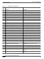
CONTENTS
Preface
xv
Document Revision History
Audience
xv
Objective
xvi
xv
Document Organization
xvi
Document Conventions
xvii
Related Documentation
xviii
Obtaining Documentation and Submitting a Service Request
CHAPTER
1
Product Overview
xviii
1-1
Overview 1-1
TV CDS Software 1-3
Caching Nodes 1-4
Streamer Load Balancing 1-4
CServer Functionality 1-4
Streamer Content Delivery Applications 1-4
Content Delivery 1-5
Real-Time Splicing of MPEG-2 Transport Streams
Dynamic Modification of Playlists 1-6
Content Chunking 1-7
Trick-Mode Restriction 1-7
HTTP Live Streaming 1-7
VOD Error Repair 1-8
1-6
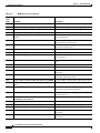
Content Delivery System Architecture 1-10
Vault 1-11
Streamer 1-12
Caching Node 1-12
Integrated Streamer-Vault 1-12
Content Delivery System Manager and Virtual Video Infrastructure Manager
Resiliency and Redundancy 1-14
Vault Disk Redundancy 1-14
Vault Server Resiliency 1-15
Vault Group Redundancy 1-16
Streamer Disk Redundancy 1-16
1-12
Cisco TV CDS 2.5 ISA Software Configuration Guide
OL-24788-01
iii
Contents
Streamer Server Resiliency 1-16
Caching Node Disk Redundancy 1-16
Caching Node Resiliency 1-16
CDSM Redundancy 1-17
Ethernet Link Resiliency 1-17
Scalability 1-17
CHAPTER
2
Network Design
2-1
Overview 2-1
CDS with Vaults and Streamers
CDS with ISVs 2-2
CDS with Caching Nodes 2-2
2-1
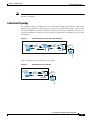
TV CDS and VVI Topologies 2-2
Centralized Topology 2-3
Decentralized Topology 2-4
Hybrid Topology 2-5
TV VVI Management 2-6
Centralized Management 2-7
Split-Domain Management 2-7
CDS Workflow 2-7
Popularity-Based Caching 2-8
Bandwidth Manager for Thin Pipe
Streamer Workflow 2-9
Setup Server 2-10
Control Server 2-10
Play Server 2-10
Caching Node Workflow 2-10
Vault Workflow 2-11
2-8
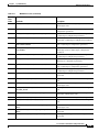
Vault Virtualization 2-12
ISA Regionalization 2-12
Centralized Storage 2-12
Remote Site 2-13
Ingest Driver 2-13
Remote Ingests 2-14
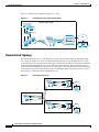
Remote Streaming 2-15
Shared Content Store 2-15
Virtual Content Store 2-16
BMS Considerations for ISA Environments
OpenStream ISA Integration 2-17
2-17
Cisco TV CDS 2.5 ISA Software Configuration Guide
iv
OL-24788-01
Contents
Streaming Mode 2-18
Steering Ingests 2-18
Network Connections 2-19
Ingest Interface 2-22
Management Interface 2-23
Cache Interfaces 2-23
Cache/Stream Interfaces 2-23
Streaming Interface 2-23
CHAPTER
3
Getting Started
3-1
Initially Configuring the Devices
Logging In to the TV CDSM
Logging Out 3-3
3-1
3-1
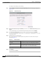
Initializing the CDS and Activating the Optional Features
3-3
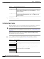
Navigating the CDSM 3-4
Using Online Help 3-5
Configuration Workflows 3-5
CDS Configuration Workflow 3-6
VVI Configuration Workflow 3-7
Central Management Configuration Workflow 3-7
Split-Domain Management Configuration Workflow 3-8
Vault Virtualization Configuration Workflow 3-9
ISA Regionalization Configuration Workflow 3-9
Virtual Content Store Configuration Workflow 3-10
TV MediaX Configuration Workflow 3-11
TV Playout Configuration Workflow 3-12
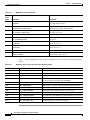
CHAPTER
4
Configuring the CDS
4-1
System Level Configuration 4-1
Configuring System Level DNS Services 4-2
Configuring System Level NTP Services 4-3
Configuring the Hosts Service 4-3
Configuring the Array Name 4-4
Configuring QAM Gateways 4-4
Stream Steering 4-4
ARP 4-5
Configuring the Headend Setup 4-9
Service Groups for Barker Streams 4-9
Gigabit Ethernet Streaming 4-10
Cisco TV CDS 2.5 ISA Software Configuration Guide
OL-24788-01
v
Contents
ASI Streaming 4-11
Configuring Stream Destinations 4-17
Configuring Parent/Child Service Groups 4-19
Configuring Distributed/ Shared ISA Settings 4-20
Configuring the Ingest Manager 4-23
Configuring Ingest Tuning 4-26
Configuring MPEG Tuning 4-29
Configuring IP Nicknames 4-31
Configuring the Ingest Driver Server 4-32
Configuring the Media Importer/Exporter 4-33
Configuring Call Signs 4-35
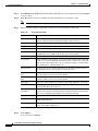
Configuring Input Channels 4-37
Configuring Output Channels 4-39
Configuring the System Level Logging 4-39
Configuring the System Level Syslog 4-41
Configuring System Level Error Repair 4-42
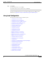
Array Level Configuration 4-43
Configuring the Array Level DNS 4-44
Configuring the Array Level NTP Server 4-44
Configuring the Streamer for BMS Connectivity 4-45
Configuring the Vault for BMS Connectivity 4-50
Grouping Stream Groups into VHOs 4-54
Configuring VHO ISA Settings 4-55
Configuring Stream Groups 4-58
VVI with Split-Domain Management and CCP Streamers 4-59
Configuring Vault Groups 4-61
Configuring Ingest Steering 4-63
Configuring Cache Groups 4-65
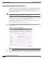
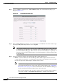
Mapping Vault Groups to Cache Groups 4-66
Mapping Cache Groups to Cache Groups 4-67
Mapping Stream Groups to Cache-Fill Sources 4-68
Mapping Vault Groups for Redundancy 4-69
Configuring the Master Vault Group 4-71
Configuring the Control and Setup IPs 4-72
Configuring Sites 4-73
Configuring Cache-Fill Bandwidth Using Thin Pipe Mapping 4-74
Configuring the Ingest Driver Client 4-77
Configuring the Media Scheduler 4-79
User Preferences 4-80
Scheduling Content for Ingest 4-81
Cisco TV CDS 2.5 ISA Software Configuration Guide
vi
OL-24788-01
Contents
Package Metadata Editor 4-84
Fixing Conflicts in the Media Scheduler 4-86
Configuring Barker Streams 4-87
Gigabit Ethernet Streaming 4-87
ASI Streaming 4-88
Configuring SSV Groups 4-90
Configuring Manual Ingests 4-91
Configuring Barker Stream/Playlists 4-94
Gigabit Ethernet Streaming 4-94
ASI Streaming 4-96
Configuring Playout Scheduler 4-98
Changing Current Timeslots 4-105
Exporting a Playout Schedule 4-106
Exporting a Playout Schedule for an EPG 4-107
Configuring Array Level Error Repair 4-107
Server Level Configuration 4-109
Configuring the Interfaces 4-109
Configuring the Servers 4-112
Configuring QoS Settings 4-116
Configuring the Route Table 4-118
CServer Source Route Type 4-119
CServer Destination Route Type 4-119
Stream Control Route Type 4-119
Configuring the SNMP Agent 4-121
Configuring the Server Level DNS 4-125
Configuring the Server Level NTP 4-126
Other NTP Configurations 4-127
Configuring the Server Level Logging 4-128
Configuring the Server Level Syslog 4-130
Configuring Server Level Error Repair 4-131
CHAPTER
5
System Monitoring
5-1
System Level Monitoring 5-1
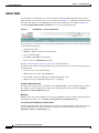
Alarms Table 5-2
System Health 5-3
System Snapshot 5-5
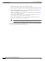
Monitoring Content Objects 5-6
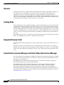
Ingests 5-7
Viewing and Deleting Completed Ingests
5-7
Cisco TV CDS 2.5 ISA Software Configuration Guide
OL-24788-01
vii
Contents
Viewing Other Ingests
Package Expirations 5-13
Publish Failures 5-14
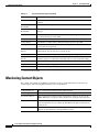
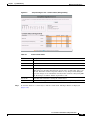
Monitoring Stream Objects
Stream Monitor 5-16
System Failures 5-21
5-12
5-16
Array Level Monitoring 5-31
Array Snapshot 5-31
Barker Stream Monitor 5-31
Playout Monitor 5-32
Server Level Monitoring 5-33
Disk Monitor 5-33
S.M.A.R.T 5-35
NIC Monitor 5-35
Server Vitals 5-37
Cache/Fill Bandwidth 5-38
Services Monitor 5-40
Recommended Monitoring Schedule 5-41
Daily Tasks 5-41
Weekly Tasks 5-42
Monitoring Tasks for Streamers and Vaults
Monitoring Tasks for Vaults 5-43
Monitoring Tasks for Streamers 5-44
Monthly Tasks 5-44
Other Tasks 5-44
CHAPTER
6
System Reporting
5-42
6-1
Stream Activity 6-1
Capacity Planning 6-2
Streams by Array 6-7
Streams by Time 6-13
Streams per STB-MAC 6-16
Stream Play History 6-19
Cache/Fill Bandwidth 6-24
System Failures 6-27
Content Popularity 6-32
Content Activity 6-35
Content by Ingest Date 6-35
Unpublished Package Report 6-37
Cisco TV CDS 2.5 ISA Software Configuration Guide
viii
OL-24788-01
Contents
CDSM Audit Logs
6-38
Playout/Barker Reports
6-41
Archived Data 6-42
CDSM Audit Log Archives 6-43
Content Reports 6-43
Stream Reports 6-44
Stream Failure Reports 6-44
Stream Activity Reports 6-45
CHAPTER
7
System Maintenance
7-1
User Access 7-2
Adding Users 7-4
Add User—Force Password Change 7-4
Editing User Settings 7-5
Deleting a User 7-6
Viewing User Settings 7-6
Changing User Default Settings 7-6
Configuring System Authentication Settings 7-9
Password Complexity Rules 7-10
Configuring User Authentication 7-10
Server Maintenance 7-11
Restarting a Server 7-11
Shutting Down a Server 7-11
Offloading a Server 7-12
Server Offload—Online 7-13
Setting System Thresholds 7-13
Restarting the Services
Content Manager
7-15
7-15
Software Maintenance 7-17
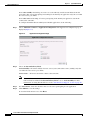
Viewing the Software Version and Server Information 7-17
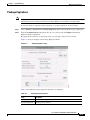
Configuring the TV Playout Application 7-17
Importing a TV Playout Schedule 7-19
Upgrade Status of the TV Playout Application 7-19
Uploading an EPG File 7-20
Identifying Server IDs and Group IDs for VVI with Split-Domain Management
Generating Server IDs and Group IDs from the VVIM 7-20
Generating a Server ID from the Stream Manager 7-22
System Cleanup 7-23
Manuals
7-20
7-24
Cisco TV CDS 2.5 ISA Software Configuration Guide
OL-24788-01
ix
Contents
APPENDIX
A
Troubleshooting
A-1
OpenStream Issues A-2
CDS Server Cannot Register with OpenStream
OpenStream Reports Alert Messages A-3
A-2
General Information and Issues A-3
File System A-4
CDSM A-4
Vault, Streamer, Caching Node, and ISV A-4
Log Files A-5
Linux Log Files A-5
CServer Log Files A-5
ISA Log Files A-7
CDSM Log Files A-8
Server Configuration Files A-8
Description of the .arroyorc Settings A-9
Description of the setupfile Settings A-10
Identifying the Software Versions or Releases A-14
Linux OS Version A-14
CDS-Related Releases A-14
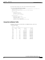
Using ifstats to Monitor Traffic A-15
Kernel Crash A-16
Disk Drive Issues A-17
CDSM GUI Disk Monitor Page Reports a Disk Warning
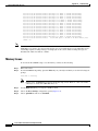
Memory Issues A-18
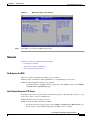
Network A-19
No Output on the NSG A-19
Vault Cannot Connect to FTP Server A-19
Checking Network Configuration A-20
Interface Information A-21
A-17
Startup Issues A-22
BIOS Settings—Operating System Hangs or Goes into KDB Mode
Serial Console Port Settings A-23
Required Services Not Starting or Running Correctly A-24
Management and Database Issues A-24
System Health A-24
Cannot Access the CDSM GUI A-25
CDSM GUI Does Not Register the Vaults and Streamers
Database Monitoring A-26
Ingest Issues
A-22
A-25
A-26
Cisco TV CDS 2.5 ISA Software Configuration Guide
x
OL-24788-01
Contents
Ingest Interface A-26
General Tips A-26
Common Ingest Problems A-26
CDS Is Not Registered to the Name Service
Restarting the ISA Services A-27
Bad Content A-27
Network A-27
A-27
Content Processing Issues A-28
Listing Content A-28
Content Mirroring A-29
Verifying GOIDs A-29
Trick-Mode Issues A-30
Name and Notify Services A-30
CORBA Interface A-30
Cache-Fill Issues A-31
Tracking Cache-Fill Source A-31
Rules for ISV Interoperability with Vaults and Streamers A-31
Network A-32
Stream Stops Playing at the Same Place or Does Not Play at All
A-32
Streaming and Playout Issues A-32
Listing of Streams A-33
No Streaming A-33
Stream Not Playing A-33
Tuning Failure A-34
Restarting the ISA Services A-34
Poor Video or Audio Quality A-34
Session Messaging
A-35
Database Issues A-36
Database Replication A-36
CDSM GUI Does Not Report All the Ingested Content
Many Log Files A-37
Corruption Recovery A-37
A-36
Advanced Features and Applications A-38
Live Multicast Ingest A-38
Ingest with Media Scheduler A-38
Ingest without Media Scheduler A-39
Ingest Troubleshooting A-39
Barker Stream A-39
Frequently Asked Questions
A-39
Cisco TV CDS 2.5 ISA Software Configuration Guide
OL-24788-01
xi
Contents
Reliability and Availability A-39
Serviceability and Manageability A-40
Content A-42
Other A-43
CDS Content Quality Guidelines A-45
Supported Elementary Stream Types
Scrambling A-45
Transport Bit Rate A-45
Stream Length A-45
Format Restrictions A-46
Preferred Formats A-46
APPENDIX
Creating Bulk Configuration Files
B
Introduction
A-45
B-1
B-1
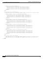
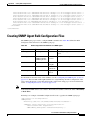
Creating QAM Gateway and Headend Setup Bulk Configuration Files B-2
QAM Gateway and Headend Setup Bulk Configuration for Gigabit Ethernet Streaming
QAM Gateway with Gigabit Ethernet Streaming Bulk Configuration B-2
Headend Setup with Gigabit Ethernet Streaming Bulk Configuration B-3
QAM Gateway and Headend Setup Bulk Configuration for ASI Streaming B-4
Creating Stream Destination Bulk Configuration Files
Creating Route Table Bulk Configuration Files
Creating SNMP Agent Bulk Configuration Files
APPENDIX
Creating NTP Server Bulk Configuration Files
B-13
OpenStream/ISA
APPENDIX
D
B-14
C-1
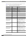
C-1
SNMP MIB and Trap Information
Overview D-1
SNMP Agent
D-1
D-1
SNMP Management Objects and Traps
RFC Compliance
APPENDIX
E
B-11
B-12
BMS Communication
C
B-9
B-10
Creating DNS Server Bulk Configuration Files
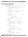
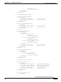
Bulk Configuration XML Schema
B-2
D-2
D-6
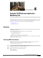
Using the TV CDS Streamer Application Monitoring Tool
Overview E-1
Initializing AMT on the Streamer
E-1
E-1
Cisco TV CDS 2.5 ISA Software Configuration Guide
xii
OL-24788-01
Contents
Logging In to AMT
E-2
AMT Statistics E-3
Viewing Error Repair Statistics E-5
Viewing Excess Bandwidth E-7
APPENDIX
F
Engineering Access Level Pages
CDSM or VVIM Diagnostics F-2
CIDR Calculator F-2
Stream Trick-Mode Debugger
Unix Timestamp Tool F-2
Server Diagrams F-2
F-1
F-2
CDSM or VVIM Setup F-3
Deployed CServer Version F-3
Stream Failover Support F-3
Stream Steering Mode F-3
Deployment Network Config F-3
Installation Type F-3
Stream Destination F-4
NAT Support F-4
Parent/Child Service Groups F-4
Bulk Configuration F-5
Trick Mode Capture F-5
Fail Ingest Tuning F-5
Vault Groups F-5
nDVR F-6
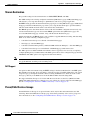
Thin Pipe Management F-6
VOD Error Repair F-6
Virtual Video Infrastructure F-7
Configuring Split-Domain Management
Configuring ISA Regionalization F-8
Configuring Virtual Content Store F-9
Content Storage F-9
Shared F-9
Distributed F-10
Media Scheduler F-10
Real-Time Capture Type F-11
Playout Scheduler F-11
Ingest Manager F-11
Ingest Steering F-12
F-8
Cisco TV CDS 2.5 ISA Software Configuration Guide
OL-24788-01
xiii
Contents
CDSM or VVIM NAV Setup F-12
CDSM or VVIM Health Monitoring
F-12
System Configs F-12
Group Map 0 F-12
Servers Group Map F-12
Popularity Based Caching F-12
Add New Server F-13
APPENDIX
G
Software Licensing Information
Notices
G-1
G-1
Product Warranties
G-1
Cisco TV CDS 2.5 ISA Software Configuration Guide
xiv
OL-24788-01
Preface
This preface describes the audience, use, and organization of the Cisco TV CDS 2.5 ISA Software
Configuration Guide. The preface also outlines the document conventions and support information.
This preface contains the following sections:
•
Document Revision History, page xv
•
Audience, page xv
•
Objective, page xvi
•
Document Organization, page xvi
•
Document Conventions, page xvii
•
Related Documentation, page xviii
•
Obtaining Documentation and Submitting a Service Request, page xviii
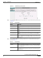
Document Revision History
The Document Revision History table below records technical changes to this document.
Document Revision
Date
Change Summary
OL-24788-01
October 2011
Initial release
Audience
This guide is for the networking professional managing the Cisco TV Content Delivery System,
hereafter referred to as CDS. Before using this guide, you should have experience working with the Cisco
IOS software and be familiar with the concepts and terminology of Ethernet, local area networking, and
TV streaming.
Cisco TV CDS 2.5 ISA Software Configuration Guide
OL-24788-01
xv
Preface
Objective
This guide provides the information you need to configure and monitor the Cisco TV CDS.
This guide provides procedures for using the commands that have been created or changed for use with
the Cisco TV CDS. It does not provide detailed information about these commands.
This guide does not describe system messages you might encounter or how to install your CDS. For
information on installing the hardware, see the Cisco Content Delivery Engine 100/200/300/400
Hardware Installation Guide, the Cisco Content Delivery Engine 110 Hardware Installation Guide, or
the Cisco Content Delivery Engine 205/220/250/420 Hardware Installation Guide. See the “Related
Documentation” section on page xviii for links to documentation online.
For documentation updates, see the release notes for this release.
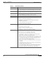
Document Organization
This document contains the following chapters and appendices:
Chapter or Appendix
Descriptions
Chapter 1, “Product Overview”
Provides an overview of the Content Delivery System.
Chapter 2, “Network Design”
Describes the possible network topologies for the
Content Delivery System.
Chapter 3, “Getting Started”
Describes accessing and navigating the Content Delivery
System Manager (CDSM).
Chapter 4, “Configuring the CDS”
Describes how to configure the CDS using the CDSM
web-based user interface.
Chapter 5, “System Monitoring”
Explains how to monitor the CDS components using the
CDSM.
Chapter 6, “System Reporting”
Explains the different reports available through the
CDSM.
Chapter 7, “System Maintenance”
Explains how to install software updates, restart services,
add administrator users, and shut down and reboot the
servers.
Appendix A, “Troubleshooting”
Presents troubleshooting procedures for the CDS,
including the symptoms, probable causes, and
recommended actions for a variety of problems.
Appendix B, “Creating Bulk Configuration Provides information on creating Bulk Configuration
Files”
XML files.
Appendix C, “BMS Communication”
Describes the mandatory values between the business
management system (BMS) and the CDS to ensure
communication between them.
Appendix D, “SNMP MIB and Trap
Information”
Provides information on SNMP and the Cisco TV CDS
proprietary SNMP informational events and traps.
Cisco TV CDS 2.5 ISA Software Configuration Guide
xvi
OL-24788-01
Preface
Chapter or Appendix
Descriptions
Appendix F, “Engineering Access Level
Pages”
Describes the CDSM pages visible with the Engineering
access level.
Appendix G, “Software Licensing
Information”
Provides information on open-source licenses and
Cisco’s software licensing agreement.
Document Conventions
This guide uses the following conventions for command syntax descriptions and textual emphasis:
Conventions
Descriptions
boldface font
Commands and keywords are in boldface.
italic font
Arguments for which you supply values are in italics.
[ ]
Elements in square brackets are optional.
{x | y | z}
Alternative, mutually exclusive, keywords are grouped in braces and
separated by vertical bars.
[x | y | z]
Optional alternative keywords are grouped in brackets and separated by
vertical bars.
string
A nonquoted set of characters. Do not use quotation marks around the string
or the string will include the quotation marks.
screen
font
Terminal sessions and information the system displays are in screen font.
boldface screen
italic screen
Caution
font
font
Information you must enter is in boldface screen font.
Arguments for which you supply values are in italic screen font.
^
The symbol ^ represents the key labeled Control—for example, the key
combination ^D in a screen display means hold down the Control key while
you press the D key.
< >
Nonprinting characters, such as passwords, are in angle brackets in contexts
where italics are not available.
!, #
An exclamation point ( ! ) or a pound sign ( # ) at the beginning of a line of
code indicates a comment line.
Means reader be careful. In this situation, you might do something that could result in equipment
damage or loss of data.
Note
Means reader take note. Notes contain helpful suggestions or references to materials not contained in
this publication.
Tip
Means the following information might help you solve a problem.
Cisco TV CDS 2.5 ISA Software Configuration Guide
OL-24788-01
xvii
Preface
Related Documentation
These documents provide complete information about the CDS and are available from Cisco.com:
•
Release Notes for the Cisco TV CDS 2.5.2
•
Cisco TV CDS 2.5 RTSP Software Configuration Guide
•
Cisco TV CDS 2.5 API Guide
•
Cisco TV CDS 2.5 Installation, Upgrade, and Maintenance Guide
•
Cisco Content Delivery Engine 100/200/300/400 Hardware Installation Guide
•
Cisco Content Delivery Engine 110 Hardware Installation Guide
•
Cisco Content Delivery Engine 205/220/250/420 Hardware Installation Guide
•
Cisco Content Delivery System 2.x Documentation Roadmap
•
Regulatory Compliance and Safety Information for Cisco Content Delivery Engines
You can access the software documents at the following URL:
http://www.cisco.com/en/US/products/ps7127/tsd_products_support_series_home.html
You can access the hardware documents at the following URL:
http://www.cisco.com/en/US/products/ps7126/tsd_products_support_series_home.html
Obtaining Documentation and Submitting a Service Request
For information on obtaining documentation, submitting a service request, and gathering additional
information, see the monthly What’s New in Cisco Product Documentation, which also lists all new and
revised Cisco technical documentation, at:
http://www.cisco.com/en/US/docs/general/whatsnew/whatsnew.html
Subscribe to the What’s New in Cisco Product Documentation as a Really Simple Syndication (RSS) feed
and set content to be delivered directly to your desktop using a reader application. The RSS feeds are a free
service and Cisco currently supports RSS version 2.0.
Cisco TV CDS 2.5 ISA Software Configuration Guide
xviii
OL-24788-01
CH A P T E R
1
Product Overview
This chapter provides a brief introduction to the Cisco TV Content Delivery System for an Interactive
Services Architecture (ISA) environment. This chapter covers the following major topics:
•
Overview, page 1-1
•
Content Delivery System Architecture, page 1-10
Overview
The Cisco TV Content Delivery System (CDS) is a distributed network of Content Delivery Engines
(CDEs) running Content Delivery Applications (CDAs) that collaborate with each other to deliver
personalized entertainment and interactive media to subscribers.
The Cisco TV CDS has a variety of mechanisms to accelerate the distribution and delivery of content.
The CDS interoperates with electronic program guides (EPGs), set-top boxes (STBs), and backoffice
applications, offering an end-to-end solution for video delivery systems.
The Cisco TV CDS functionality can be separated into five areas:
•
Ingest
•
Storage
•
Caching
•
Streaming
•
Management
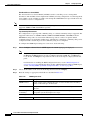
Each CDE in the CDS contributes to one or more of these functions as determined by the CDAs running
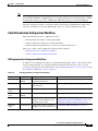
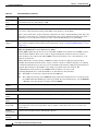
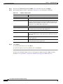
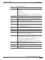
on it. Table 1-1 describes the relationship between the CDA names and the names the TV Content
Delivery System Manager (CDSM) uses.
Table 1-1
CDA Mapping to Functionality and CDSM
CDA Name
Functionalities
CDSM Device Name
Vault
Ingest and storage
Vault
Content Cache
Content distribution between Vaults and Streamers
Caching Node
TV Streamer
Content caching, personalization, and streaming to STBs Streamer
Cisco TV CDS 2.5 ISA Software Configuration Guide
OL-24788-01
1-1
Chapter 1
Product Overview
Overview
Table 1-1
CDA Mapping to Functionality and CDSM (continued)
CDA Name
Functionalities
CDSM Device Name
TV MediaX Suite
Aids content ingest workflow and scheduling tasks for
both asset-based and real-time content
CDSM
TV Content
Delivery System
Manager
Management
CDSM
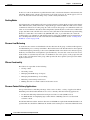
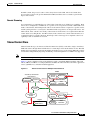
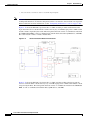
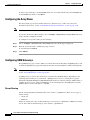
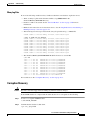
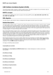
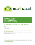
Figure 1-1 illustrates how a TV CDS network can be deployed. A business management system (BMS),
commonly called a backoffice, enables service providers to deploy on-demand services using video on
demand (VOD) servers, networks, billing systems and other system components. The asset management
system (AMS) manages the content on headend and node servers, while the BMS handles functions
related to pitching and catching. Sometimes there is some overlap of functionality between the BMS and
the AMS.
There are two types of systems available with the TV CDS: a CDS with an array of Vaults and Streamers,
and a Virtual Video Infrastructure (VVI) with an array of Vaults, Caching Nodes, and Streamers. The
CDSM manages the Vaults and Streamers in a CDS. The VVIM manages the Vaults, Caching Nodes, and
Streamers in a VVI with centralized management. For more information about network design and VVI
management, see the “TV CDS and VVI Topologies” section on page 2-2. Figure 1-1 shows a high-level
view of both a CDS and a VVI.
High-Level System View of Content Delivery System and Virtual Video Infrastructure
Asset
Management
System
Business
Management
System
Metadata
Streamer Array
Raw
Data
Content
Provider
Switched
Network
4-6 GigE
Vault Array
Management
1-12 GigE
1-12GigE
1-12GigE
Switched
Network
Switched
Network
GigE
RF
Management
CDSM
(VVIM)
RF Devices
Management
Set-top Box
Caching Nodes
HFC
252020
Figure 1-1
The Cisco TV CDS solution has three major elements:
•
One or more Vault Groups consisting of one or more Vaults. The Vaults are responsible for ingest
and reliable storage of VOD content. The number of Vaults in the Vault Group, and the number of
Vault Groups is driven by the amount of content that the system offers and the degree of redundancy.
Cisco TV CDS 2.5 ISA Software Configuration Guide
1-2
OL-24788-01
Chapter 1
Product Overview
Overview
Note
•
One or more Stream Groups each consisting of one or more Streamers. The Stream Group is
responsible for the personalization and streaming of content in response to user requests. The
number of Streamers and Stream Groups is determined by the number of streams deployed and by
the topology that best suits your individual network and redundancy requirements.
•
The CDSM is used to manage the Vaults, Streamers, and Caching Nodes in the same array, collects
event logs, and provides reporting tools.
In smaller systems, the Integrated Streamer-Vault (ISV) server can be used, where the Vault and
Streamer functionalities exist in one ISV server.
The Cisco TV VVI solution has four major elements:
•
One or more Vault Groups consisting of one or more Vaults. The Vaults are responsible for ingest
and reliable storage of video on demand (VOD) content. The number of Vaults in the Vault Group,
and the number of Vault Groups is driven by the amount of content that the system offers and the
degree of redundancy.
•
One or more Cache Groups, consisting of one or more Caching Nodes. The Caching Nodes provide
more flexibility in designing a multi-tiered Virtual Video Infrastructure (VVI) by acting as a tier
between the Vaults and the Streamers. The Caching Nodes facilitate content distribution and remove
distribution traffic from the network backbone.
•
One or more Stream Groups each consisting of one or more Streamers. The Stream Group is
responsible for the personalization and streaming of content in response to user requests. The
number of Streamers and Stream Groups is determined by the number of streams deployed and by
the topology that best suits your individual network and redundancy requirements.
•
The CDSM is used to manage the Vaults, Streamers, and Caching Nodes in the same array, collect
event logs, and provide reporting tools. In a split-domain management system configuration, there
is a Stream Manager that manages all the Streamers, and a Virtual Video Infrastructure Manager
(VVIM) that manages all the Vaults and Caching Nodes.
TV CDS Software
The Cisco TV CDS kernel software, known as the CServer, creates a logical network that pools, load
balances, and coordinates the physical resources of the CDEs, so that the whole network operates and is
managed as if it is a single resource.
The CServer facilitates the rapid movement of content between Vaults and Streamers while keeping
required bandwidth to a minimum. To accomplish this, the Cisco TV CDS software uses a proprietary
protocol, the Cache Control Protocol (CCP), across the gigabit Ethernet networks. All content is held
reliably on the Vault servers and a large amount, but not all, of the content is also contained on the
Streamer servers. Cisco CCP, a multilayered caching architecture, along with associated software
algorithms ensures that content segments are delivered only to the Streamers where there is demand for
that content. The TV CDS software monitors the frequency of subscriber demand and places content
appropriately in either the dynamic random access memory (DRAM) or disk cache of the serving
Streamer.
Content is delivered across the network in response to cache-fill calls from the Streamers in an
opportunistic manner, depending on the availability of bandwidth; delivery can be faster than real-time
delivery where bandwidth allows. The TV CDS software ensures content on the Streamer servers is
always the most popular content; that is, the content requested by the largest number of subscribers. User
requests are generally served from the cache on the Streamer. Requests for content that are not already
Cisco TV CDS 2.5 ISA Software Configuration Guide
OL-24788-01
1-3
Chapter 1
Product Overview
Overview
in the local cache of the Streamer are pulled from the Vault, cached on the Streamer, and streamed to the
subscriber. Wherever the content is stored relative to the point of playout, all content appears as if it is
local to the Streamer and the streaming of any content is nearly instantaneous.
Caching Nodes
A Caching Node is an intermediary fill source for the Streamers. Caching Nodes are deployed in Virtual
Video Infrastructures (VVIs). The VVI is a deployment type of the TV CDS. In a CDS, servers cannot
communicate with servers in other groups. In a VVI, servers in other groups can communicate with each
other on an as needed basis. Streamers and Caching Nodes dynamically discover fill sources within other
groups. Streamers send cache-fill calls to remote servers (Streamers in other Stream Groups and Caching
Nodes) for content that is not found locally (DRAM, disk cache, or peer Streamers). In a VVI, the
Caching Nodes can communicate with the Streamers by using CCP or HTTP. For more information on
how a Caching Node interfaces with a CCP Streamer and an HTTP Streamer, see the “Caching Node
Workflow” section on page 2-10.
Streamer Load Balancing
To ensure that new streams are distributed to the best Streamer in the group, each Stream Group runs a
load distribution protocol among its members. The best Streamer is the Streamer that has the requested
content in the highest-performing cache resource (DRAM or disk) or that has the most unused capacity.
In this way, new Streamers are brought into operation hitlessly—because after a new server is in service,
fresh streams are automatically allocated to it. Furthermore, the cache capacity of the group is the sum
of the caches of all Streamers in the group, which provides the most optimal system operation and the
highest cache-hit rate.
CServer Functionality
The CServer is responsible for the following:
•
Storing content
•
Streaming content
•
Managing bandwidth usage for ingests
•
Managing bandwidth usage for streaming
•
Mirroring content among Vault servers
•
Making decisions on content retention on Streamer servers
Streamer Content Delivery Applications
On top of the CServer, and taking advantage of the services it offers, a variety of applications deliver
individual personalized entertainment services. Cisco currently offers the following applications:
•
TV Streamer delivering VOD and network personal video recorder (nPVR) services
•
TV MediaX Suite for simplifying ingest and workflow scheduling tasks for asset-based and
real-time content
In a full TV CDS network, the Vault, TV Streamer, and CDSM are required. The TV MediaX Suite is an
optional CDA. In a smaller TV CDS network, the ISV can be used in place of the Vault and TV Streamer.
Cisco TV CDS 2.5 ISA Software Configuration Guide
1-4
OL-24788-01
Chapter 1
Product Overview
Overview
TV Streamer CDA
The TV Streamer CDA is used for VOD delivery systems. TV Streamers are responsible for
personalizing content and playing that content out under subscriber control.
TV MediaX Suite CDA
The TV MediaX Suite CDA offers a set of tools that simplify content ingest workflow and scheduling
tasks for both asset-based and real-time content. The TV MediaX Suite CDA consists of the following
features:
•
Publisher—Coordinates the ingest of pre-encrypted content.
•
Scheduler—Schedules real-time content or imports the schedule from an electronic program guide
(EPG).
For information on configuring TV MediaX, see the “TV MediaX Configuration Workflow” section on
page 3-11.
TV Playout CDA
The TV Playout feature is for ISA environments and includes Public, Education, and Government (PEG)
channels and Barker Streams. PEG channels differ from traditional broadcast channels in that the service
provider itself must ingest and stream the content rather than receiving and forwarding a satellite feed.
For information on configuring TV Playout, see the “TV Playout Configuration Workflow” section on
page 3-12.
Content Delivery
The CDS delivers real-time, time-shifted, and on-demand video content to set-top boxes, personal
computers, or any other device accessible through a Service Provider network.
The Cisco VVI allows service providers to support a broad range of services. For example, with the
ability to distribute content from anywhere to anywhere, operators can provide user-generated and online
video just as easily as any other on-demand title. The ability to deliver content with sub-second latency
also lets service providers dramatically expand the video library that can be made immediately
accessible to customers, allowing them to access content that resides in a different state or country
virtually instantly.
Operators can also support popular real-time and time-shifted services, such as letting viewers tuning
into a program in progress and restart it from the beginning, or providing network-based personal video
recorder (nPVR) functions such as the ability to pause, fast forward, and rewind live TV. The Cisco
VVI's centralized storage and localized streaming architecture also distributes screen-formatting
processes to the network edge.
The key content delivery capabilities include the following:
•
Supports multiple content formats (high-definition and standard-definition content, multiple video
codec formats, multiple media file types, and so on)
•
Supports ingest and streaming of real-time video services, VOD services, and Internet video
•
Supports advertising content distribution and streaming
•
Supports nPVR capabilities to provide a digital video recorder (DVR)-like experience with the
network
Cisco TV CDS 2.5 ISA Software Configuration Guide
OL-24788-01
1-5
Chapter 1
Product Overview
Overview
•
Provides a single content delivery network for serving set-top boxes (STBs), PCs, and mobile
devices
•
Supports content security and encryption
•
Supports narrowcast service such as VOD, time-shifted TV, and switched digital video (SDV)
sharing the same infrastructure
•
Supports both traditional and next-generation STBs and headends
Real-Time Splicing of MPEG-2 Transport Streams
The ISA Stream Extensions feature allows real-time splicing of MPEG-2 transport streams as identified
by the Society of Telecommunications Engineers (SCTE) 35 standard. The embedded SCTE 35 cue
messages contain information for digital program insertion (including advertisement insertion) in live
content as well as content recorded for the purpose of enabling time-shifted on-demand services.
Pre-roll, post-roll, and mid-roll placements of digital program insertion, that is based on a playlist
structure, is supported on a CDS in an ISA environment. The Vault detects the SCTE-35 cues and
processes them at the time of ingest. The StreamExtChannel event channel on the CORBA
NotificationService is used to send ContentSignalingEvents that contain the SCTE-35 cue information
to the backoffice.
Note
The SCTE-35 cue message cannot be greater than 400 bytes.
CDSM Configuration
To configure this feature set the TME/SCE field to Enable for MystroMDN.
The TME/SCE field is located on different CDSM pages, depending on the type of system configured
(VVI or CDS).
Note
•
In a VVI with split-domain management, on the VVIM GUI, choose Configure > System Level >
Distributed ISA Setup or Configure > System Level > Shared ISA Setup
•
In a VVI with split-domain management, on the Stream Manager, choose Configure > Array Level
> VHO ISA Setup
•
In a VVI with central management or a legacy CDS, choose the Configure > Array Level >
Streamer BMS
The configuration change for the ISA Stream Extensions feature requires that the ISA service is restarted
on both the master Vault and the Master Streamer. To identify the master Streamer and master Vault, use
the CDSM Monitor Services page to find the Streamer running the master stream service and the Vault
running the Content Store master. See the “Services Monitor” section on page 5-40 for more
information. To restart the ISA service, choose Maintain > Services, select the check box for ISA, and
click Submit.
Dynamic Modification of Playlists
The following dynamic playlists modifications can be performed on playlists that have been defined and
created:
•
Delete_Segment—Remove a segment from the playlist
•
Replace_Segment—Replace a segment in the playlist with one or more segments
Cisco TV CDS 2.5 ISA Software Configuration Guide
1-6
OL-24788-01
Chapter 1
Product Overview
Overview
Note
•
Splice_Segment—Insert one or more segments at a specified NPT start value or NPT end value
within an existing playlist segment
•
Add_Segment—Add one or more segments after a segment in the playlist
Each playlist can have up to 64 content elements.
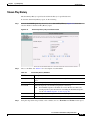
The CDSM provides augmentations to the Stream Play History report. The Stream Play History report
first displays the Session ID Summary. When a session ID is clicked, if a playlist was streamed for the
session, the Session Playlist History report is displayed.
Note
The Trick Mode Capture feature must be enabled to access the Stream Play History reports.
Content Chunking
For DVD on Demand solutions and long recordings, Release 2.5.2 supports ingest and streaming of
assets up to 120 GB in size and recordings that last longer than 12 hours. This is accomplished by
dividing the asset into multiple chunks of approximately 16 GB each.
Note
The Content Chunking feature is disabled by default. All the CDS servers in a deployment must be
upgraded before enabling this feature. To enable, the following line must be added to the setupfile of
each CDS server and the server must be rebooted: content id type 2
Trick-Mode Restriction
Restriction of trick-mode controls (pause, rewind, fast-forward) per playlist segment is supported.
If a client issues a trick-mode command for a locked-out playlist segment or attempts to bypass a
trick-mode restricted segment by jumping to the next segment, an LSC_NOT_PERMITTED response is
sent to the set-top box. If a client has sent a fast-forward trick-mode command and a restricted segment
is reached, the stream continues at normal play speed and an LSC_DONE response is sent to the set-top
box with the NPT of the beginning locked out segment. An LSC_NOT_PERMITTED response is also
sent to indicate that the LSC_DONE is due to a locked out trick-mode segment.
The CDSM GUI provides the ability to configure these settings on the MPEG Tuning page (Configure
> System Level > MPEG Tuning).
HTTP Live Streaming
HTTP Live Streaming is fully supported; similar to live streaming over Cache Control Protocol (CCP).
The enhancements to HTTP Live Streaming consist of the following:
•
Catch-Up to Live
•
Play While Ingesting the Same Content
Catch-Up to Live
A video player can play live content close to the live point, within 2.5 seconds of the live point, without
macroblocking or leaving artifacts on the screen of the player.
Cisco TV CDS 2.5 ISA Software Configuration Guide
OL-24788-01
1-7
Chapter 1
Product Overview
Overview
If play starts at 0 or some point before the live point, then the Catch-up to Live feature allows the
end-user to fast-forward to the live point and resume normal play at the live point. The play point will
be within 2.5 seconds of the live point.
Play While Ingesting the Same Content
While ingesting the content, a STB can request the content play start at 0, at “play now,” or at any specific
normal play time (NPT) value between 0 and the live point; and the content will begin playing at the
requested point of play.
When a set-top box (STB) sends a “play now” request, meaning the STB is requesting that the play begin
at the live point, the “play now” point is within 2.5 seconds of the live point.
VOD Error Repair
The VOD Error Repair feature retransmits lost packets to improve the quality of the end-user video
experience. The VOD Error Repair feature uses negative acknowledgement (NACK) retransmission
methods to implement retransmission-based error repair.
Note
VOD Error Repair is supported on ISA environments that use the Cisco (RTSP) setting as the LSCP
Client Protocol, and RTSP environments that use the Cisco RTSP deployment type.
In addition to UDP streaming, unicast Realtime Transport Protocol (RTP) with Realtime Transport
Control Protocol (RTCP) streaming, as well as Error Repair (ER) are supported.
The client dictates which streaming protocol is used by way of the RTSP SETUP message. The following
streaming protocols are supported in the same system with simultaneous streams of each type:
•
UDP
•
RTP
•
UDP with NAT traversal (Interactive Connectivity Establishment [ICE])
•
RTP with NAT traversal (ICE)
•
RTP with retransmission-based error repair
•
RTP with NAT traversal (ICE) and retransmission-based error repair
For sessions that use UDP, aside from RTSP messages, only the media server sends packets.
For sessions that use RTP, RTCP packets may be sent from the server to the client or from the client to
the server. The client must be aware of the server’s IP address and ports for receiving these packets.
For sessions that use NAT, the server sends its own IP address and ports as ICE candidates.
For sessions that do not use NAT, the transport header must include a “server ports” parameter.
For sessions that use RTP retransmission-based error repair, a client sends a second SETUP request to
the CDS Control server, which requires a total of four open ports. The first SETUP message has two ports
(one for RTP and one for RTCP). and the second SETUP message has two ports that carry two ICE
candidates. The URLs used for the retransmission stream are appended with the “/rtx” ending.
Following is an example of the first SETUP message:
SETUP rtsp://192.0.2.100/movie.mpg RTSP/1.0<CRLF>
CSeq: 2 <CRLF>
Transport: RTP/AVPF/UDP; unicast; destination=54.0.1.1; client_port=8998-7123,
MP2T/DVBC/UDP; unicast; destination=54.0.1.1; client_port=8998<CRLF>
Cisco TV CDS 2.5 ISA Software Configuration Guide
1-8
OL-24788-01
Chapter 1
Product Overview
Overview
RTSP/1.0 200 OK<CRLF>
CSeq: 2<CRLF>
Session: 12345678<CRLF>
Transport: RTP/AVPF/UDP; unicast; destination=54.0.1.1; client_port=8998-7123;
source=101.1.2.3; server_port=50236-50237<CRLF>
Following is an example of the second SETUP message:
SETUP rtsp://192.0.2.100/movie.mpg/rtx RTSP/1.0<CRLF>
Session: 12345678 <CRLF>
CSeq: 2 <CRLF>
Transport: RTP/AVPF/UDP; unicast; destination=54.0.1.1; client_port=8999-7124<CRLF>
<CRLF>
RTSP/1.0 200 OK<CRLF>
CSeq: 2<CRLF>
Session: 12345678<CRLF>
Transport: RTP/AVPF/UDP; unicast; destination=54.0.1.1; client_port=8999-7124;
source=101.1.2.3; server_port=50238-50239<CRLF>
<CRLF>
Note
Retransmission-based Error Repair is only available with RTP streaming.
Background
RTP packets include sequence numbers that are used to detect missing packets and reorder out-of-order
packets. RTCP is the control protocol for RTP and is used to send receiver reports from the client to the
server that include monitoring information, to send sender reports from the server to the client, and to
request retransmission, which is the RTCP NACK packet that includes the RTP sequence number.
The Streamer receives the retransmission RTCP NACK request. Each NACK request identifies one or
more missing RTP packets. The Streamer keeps a small buffer of recently transmitted packets and the
missing packets are retransmitted based on how many packets the buffer maintains.
Error Repair Client on STB
VOD Error Repair feature requires that the STB have the Cisco Visual Quality Experience Client
(VQE-C) software running on it. The VQE-C is the error-repair client software, which has the following
capabilities:
•
Receives RTP video packets
•
Detects missing packets
•
Requests retransmission of missing packets
•
Merges retransmitted packets with original stream
•
Collects statistics and counters for monitoring
The VQE-C is a software development kit (SDK) that is available for download through the open-source
program. Additionally, the STB must comply with the Cisco RTSP syntax for VOD Error Repair.
Monitoring
The play management application (PMA) log file, vqe.log, is located in the /arroyo/log directory. To
check for PMA errors, enable the PMA debug flag for the vqe_cp facility on the Logging page in the
CDSM.
Cisco TV CDS 2.5 ISA Software Configuration Guide
OL-24788-01
1-9
Chapter 1
Product Overview
Content Delivery System Architecture
AMT
Application Monitoring Tool (AMT) runs a web application on each Streamer and provides several
troubleshooting tools. For more information, see Appendix E, “Using the TV CDS Streamer Application
Monitoring Tool.”
Content Delivery System Architecture
Vaults and Streamers have different but important functions that are required for the TV CDS software
to run efficiently. The Integrated Streamer-Vault (ISV) server combines the functionality of both the
Vault and Streamer for smaller networks. The Content Delivery System Manager provides a
browser-based user interface for configuration, monitoring, maintenance, and reports of the TV Content
Delivery System solution. In a VVI, the Caching Nodes provide a pure caching layer for a multi-tiered
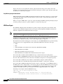
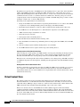
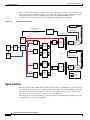
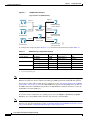
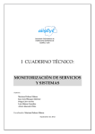
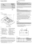
VVI. Figure 1-2 shows the different elements of the TV Content Delivery System and the TV Virtual
Video Infrastructure with the addition of the Caching Nodes.
Figure 1-2
High-Level View of the Content Delivery System and Virtual Video Infrastructure
Database
Reports
SystemManager
Mgmt
Event Collection
Mgmt
M
g
m
t
Video
Accelerator
(CServer)
Database
Database
Ingests
Vault
Server
M
g
m
t
Video
Accelerator
(CServer)
Cache Fills
Storage
Caching
Node
Video
Accelerator
(CServer)
Database
Cache Fills
Storage
Streamer
Server
Storage
Streams
203529
M
g
m
t
Mgmt
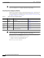
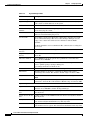
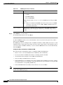
Table 1-2 describes the system elements shown in Figure 1-2.
Cisco TV CDS 2.5 ISA Software Configuration Guide
1-10
OL-24788-01
Chapter 1
Product Overview
Content Delivery System Architecture
Table 1-2
High-Level Description of the TV CDS and TV VVI
Content Delivery System
Element
Description
CServer
The CServer is the kernel software that handles bandwidth management,
storage decisions, Real Time Streaming Protocol (RTSP) and Lightweight
Stream Control Protocol (LSCP) and stream processing on the TV Content
Delivery System.
Database
The database stores information about the system, including current states
of all ingests and streams, configuration settings, and system statistics.
Some database elements are global among all servers and some are local.
For example, statistics are stored on the local server and the Content
Delivery System Manager only. States about stream objects are replicated
on all Streamer servers. The Content Delivery System Manager stores a
superset of all database elements.
Management
There are two types of management:
Storage
•
Content Delivery System Manager—Browser-based user interface
•
SNMP agent—Network Management System (NMS) interface
There are four levels of storage (or cache):
•
All content is stored on the Vault server, as well as mirrored to other
Vaults.
•
Requested content is stored on the Caching Nodes.
•
Recently requested content, or popular content is stored on the hard
drive of the Streamer.
•
Currently requested content, or popular content, is stored in the random
access memory (RAM) of the Streamer.
Event Collection
The Content Delivery System Manager collects logged events for reporting
purposes as well as for third-party applications
Reports
The Content Delivery System Manager provides a reporting tool to aid
performance trending and analysis of streams, popular content, bandwidth
usage, and more.
Vault
The Vault ingests content delivered over a standard interface (for example, using FTP to receive content
from a catcher), performs whatever processing is required (for example, generating trick-play files), and
stores the processed content reliably on disk. A Vault Group consists of a scalable number of Vaults that
divide the responsibility for ingest and storage among the members of the group. Vault servers can be
colocated or distributed to multiple locations across an IP or Ethernet network. Each Vault can
simultaneously ingest up to 160 channels of MPEG-2 transport stream (TS) content and store up to 6000
hours of MPEG-2 TS standard definition content with two mirrored copies of the content and one or two
trick files.
Cisco TV CDS 2.5 ISA Software Configuration Guide
OL-24788-01
1-11
Chapter 1
Product Overview
Content Delivery System Architecture
Streamer
A Streamer server receives content from the Vault and delivers that content to subscribers. Streamers can
be of different capacity, depending on the needs of the network, and have different applications,
depending on the type of content being delivered. Currently, the highest-capacity Streamer can
simultaneously stream approximately 2500 streams of MPEG-2 TS standard definition VOD. Streamers
can be colocated with Vaults or distributed to remote locations. The Stream Group is responsible for the
personalization and streaming of content in response to user requests.
Caching Node
The Caching Node provides a 10-Gbps throughput to facilitate the distribution of content from the Vaults
to the Streamers. The Caching Nodes allow for the ability to create a tier-based hierarchy in the CDS.
Caching Nodes are deployed in VVIs. Vaults can be strategically located for storing content on a national
network, while the Streamers are located in a regional network. The Caching Node can be colocated with
the Vaults or distributed closer to regional locations across an IP or Ethernet network. A Cache Group
consists of several Caching Nodes that divide the responsibility for distribution among the members of
the group.
The Caching Nodes use CCP to communicate with the Vaults and Streamers. Alternatively, the Caching
Nodes can use HTTP instead of CCP to communicate with Streamers.
Integrated Streamer-Vault
The Integrated Streamer-Vault (ISV) server offers the functionality of both a Vault and Streamer in one
server.
The ISV server ingests content delivered over a standard interface, performs whatever processing is
required, and stores the processed content reliably on disk. An ISV array consists of a scalable number
of ISV servers that divide the responsibility for ingest, storage, and streaming among the members of the
array.
Content Delivery System Manager and Virtual Video Infrastructure Manager
The Content Delivery System Manager (CDSM) and the Virtual Video Infrastructure Manager (VVIM)
are each a browser-based user interface accessible by a web browser program and designed to manage a
TV CDS or a TV VVI network.
The CDSM provides centralized management functions for the TV CDS, including configuration,
monitoring, troubleshooting, reporting, and maintenance.
The VVIM provides centralized management function for the TV VVI, including configuration,
monitoring, troubleshooting, reporting, and maintenance. The VVIM in a centralized domain
management configuration manages the Vaults, Caching Nodes, and Streamers, The VVIM in a
split-domain management configuration manages the Vaults and Caching Nodes, while the Streamers are
managed by the Stream Manager. For more information about split-domain management, see the “TV
VVI Management” section on page 2-6.
Cisco TV CDS 2.5 ISA Software Configuration Guide
1-12
OL-24788-01
Chapter 1
Product Overview
Content Delivery System Architecture
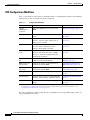
In both the CDS and VVI, all Vaults and Streamers are identified by an array ID, a group ID, and a server
ID. The array ID identifies servers that are part of the same system. The group ID identifies servers that
are part of the same group (Vault Group or Stream Group), and the server ID is a unique number that
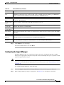
identifies the server. Table 1-3 lists the CDSM GUI ID names and maps them to the CServer names in
the setupfile and .arroyorc files.
Table 1-3
ID Names in the CDSM GUI and CServer Files
CDSM GUI ID Name
CServer Files ID Name
Array ID on the Array Name page
groupid
Group ID on the Server-Level pages
groupid
Stream Group ID on the Server Setup page
arrayid
Cache Group ID on the Server Setup page
arrayid
Vault Group ID on the Server Setup page
arrayid
Stream Group ID on the Configuration Generator page arrayid
In a VVI with CCP Streamers, similar to a CDS, all Vaults, Streamers, and Caching Nodes are identified
by an array ID, a group ID, and a server ID. The group ID and server ID in a VVI with CCP Streamers
must be unique among other groups and servers in the same system.
In a VVI with HTTP Streamers, the Vaults, Streamers, and Caching Nodes still use an array ID, a group
ID, and a server ID for identification, but there is additional functionality that allows the Vaults and
Caching Nodes to communicate using CCP, while the Caching Nodes communicate with the Streamers
using HTTP. It is not required that the group ID and server ID be unique, but it is recommended.
The CDSM and VVIM (as well as the Stream Manager) have three configuration and monitoring levels:
system, array, and server. System-wide configuration affects all servers managed by that manager. The
array-level configuration affects all the servers of the specified array or group, and the server-level
configuration applies changes to a specific server.
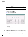
The CDSM and VVIM offer a drill-down approach to show the status of any stream or ingest point, or
the physical status of any piece of hardware.
The CDSM reporting helps operators manage all aspects of the TV CDS. Information on stream traffic,
content statistics, and server data are gathered from all servers in the network and correlated
automatically, showing at a glance the status of the network and reporting on statistics such as content
popularity, stream usage, and bandwidth usage for each service group.
The VVIM monitoring and reporting helps operators manage all aspects of the TV VVI in either a
centralized management capacity or a split-domain management capacity. In a split-domain capacity, the
VVIM monitors the ingests and the Stream Manager monitors the streams of the Streamers in its domain.
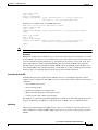
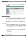
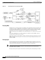
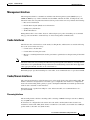
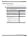
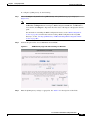
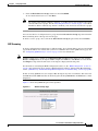
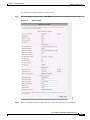
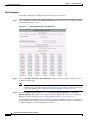
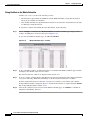
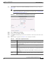
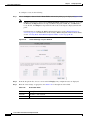
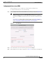
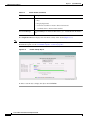
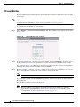
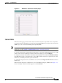
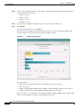
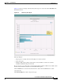
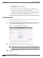
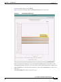
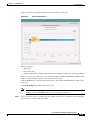
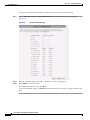
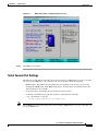
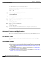
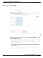
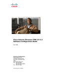
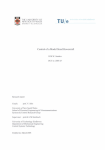
Figure 1-3 shows the system monitoring page of the CDSM.
Cisco TV CDS 2.5 ISA Software Configuration Guide
OL-24788-01
1-13
Chapter 1
Product Overview
Content Delivery System Architecture
Figure 1-3
Content Delivery System Manager User Interface
Resiliency and Redundancy
The TV Content Delivery System is designed to have no single point of failure. The TV Content Delivery
System incorporates redundancy at several levels within the architecture. These levels of redundancy
eliminate any customer impact from potential failures of Vault disks, Vault servers, Streamer disks,
Streamer servers, ISV servers, Ethernet connections, processors, and power supplies.
Each server constantly monitors the state of its peers. The TV CDS unique resource pooling and
auto-failover techniques allow all servers in the network to actively contribute to satisfying storage and
streaming demand at all times. If a server fails, the load is instantaneously redistributed among the
surviving servers, ensuring continuity of service.
Vault Disk Redundancy
The Vault server protects content through full 1:N redundancy. If a disk fails, the data is available from
a redundant server, spreading the load and optimizing the bandwidth. Additionally, the regeneration of
the redundant content utilizes the bandwidth of the whole Vault array rather than just the disk bandwidth
available inside a particular server, significantly reducing the rebuild time. The need to replace the failed
drive is not time critical in the least, making quarterly replacement of any failed Vault drives feasible.
Mirroring
The primary method to protect the content against loss because of hardware failure is mirroring. Content
is stored on a Vault and, based on the policy, it is mirrored to other locations in the Vault array. The
number of mirrored copies is configurable. There are three types of mirroring:
•
Local mirroring
•
Mirroring within an array
•
Array mirroring (from Vault Group to Vault Group)
Cisco TV CDS 2.5 ISA Software Configuration Guide
1-14
OL-24788-01
Chapter 1
Product Overview
Content Delivery System Architecture
Local Mirroring
Local mirroring defines the number of copies of each content object to maintain on the unique drives of
a single Vault. Local mirroring allows resiliency for a small installation (for example one Vault). Local
mirroring guards against a single drive failure, but does not protect against service interruption or
potential data loss in the event of a complete server failure.
Local mirroring is not configured by default, and is generally only used when there is a single Vault in
a system. Local mirroring is configured in the Configure > Server Level > Server Setup page with the
Vault Local Copies field, which corresponds to the tunable “vault local copy count” in CServer. Up to
four local copies are supported.
Mirroring within an Array
Mirroring within an array defines the number of copies of each content object in an array to maintain
across the Vaults within that array or site. Mirroring within an array guards against a single drive failure
or the failure of an entire server. The number of copies to maintain within that array is configurable in
the Configure > Server Level > Server Setup page with the Vault Mirror Copies field, which
corresponds to the tunable “vault mirror copies” in CServer. Up to 10 copies within an array are
supported.
Array Mirroring
Array Mirroring (from Vault Group to Vault Group) specifies that each content object on all of the Vaults
in one group has at least one copy on a Vault in the mirrored Vault Group. Array Mirroring is only
responsible for ensuring that a single copy of each content exists in the mirrored Vault Group. If more
than one copy of each content object is required within an array, Mirroring within an Array (not Array
Mirroring) is responsible for this task. Array Mirroring is configured in the Configure > Array Level >
Vault Redundancy Map page, which corresponds to the tunables “allow vault array mirroring” and
“vault array mirror” in CServer. Each Vault Group can have up to 3 mirrored Vault Groups configured.
Note
Array Mirroring is part of the Vault Groups feature and is only available if Vault Groups is enabled on
the CDSM Setup page. For more information, see the “Vault Groups” section on page F-5.
Vault Server Resiliency
The Cisco TV CDS can handle the loss of an entire Vault server without impacting the subscriber. The
communication with the backoffice suite is performed by a Vault server that is designated as the Vault
master. If the Vault master fails, one of the remaining slave Vault servers in the Vault array transparently
takes over as the master. The remaining Vaults detect the loss of a Vault server, run a check of all stored
content, and regenerate redundant content that was affected by the lost Vault server. This regeneration
runs in the background, utilizing spare system bandwidth that is not consumed by subscriber load,
resulting in the shortest possible regeneration window possible without compromising performance to
the subscriber.
Vault Master
The Vault master, designated by a virtual IP address on its management interface, is used as the
representative of the Vault array to the backoffice and handles the ingest of new content.
Cisco TV CDS 2.5 ISA Software Configuration Guide
OL-24788-01
1-15
Chapter 1
Product Overview
Content Delivery System Architecture
Vault Group Redundancy
In addition to the Vault server redundancy, the Cisco TV CDS offers redundancy for Vault Groups. When
the CDS is configured with Vault Group redundancy and at least two Vault Groups are configured, the
system handles the loss of an entire Vault Group without impacting the subscriber experience. Content
is mirrored among as many as four Vault Groups (one Vault Group ingests the content and up to three
Vault Groups mirror the content), which may be in different geographic regions. If the primary Vault
Group becomes unavailable, because of network, power, or other catastrophic problems, any Streamer
or Caching Node that was requesting content from that Vault Group would fail over to the other Vault
Group until the primary Vault Group came back online and could again respond to cache-fill requests for
content.
With Vault redundancy, at least one copy of each content within a group is mirrored to a configured peer
group. Vault Group mirroring runs as a low-priority process, so as not to impact the performance of the
guaranteed streaming delivery.
Note
The maximum number of Vault Groups is 20.
Streamer Disk Redundancy
The disks in the Streamer are not used for full content storage as in most VOD implementations. Rather,
the Streamer disks are part of the TV CDS multilevel caching architecture. If a disk is lost on a Streamer,
the only impact is a marginal loss of caching capability for the system. Any content that was cached on
that Streamer disk is retrieved again from the Vault. The RAM on the Streamer has enough content
cached for streaming to the subscriber, so that this refetch of content from the Vault occurs without
impacting the subscribers. For example, for a Streamer array of five Streamers with sixteen hard drives
each, a lost drive only reduces the total caching capability by less than 1.25 percent. The need to replace
the failed drive is not time critical in the least, making quarterly replacement of any failed Streamer
drives feasible.
Streamer Server Resiliency
The Cisco TV CDS architecture allows for failed Streamer servers as well. If any Streamer server fails,
the communication to the backoffice is transparently handed off to another Streamer. With the TV CDS
software, if a Streamer server fails the other Streamers recognize that failure and continue streaming to
that subscriber.
Caching Node Disk Redundancy
The disks in the Caching Node are not used for full content storage like most VOD implementations.
Rather, the Caching Node disks are part of the TV CDS multilevel caching architecture. If a disk is lost
on a Caching Node, the only impact is a marginal loss of caching capability for the system. Any content
that was cached on that Caching Node disk is retrieved again from the Vault.
Caching Node Resiliency
The Cisco TV CDS architecture allows for failed Caching Nodes as well. If a Caching Node fails, any
cache-fill transmissions that were in process at the time of the failure are re-requested by the Streamer,
and any new requests are responded to by the remaining Cache Nodes in the Cache Group.
Cisco TV CDS 2.5 ISA Software Configuration Guide
1-16
OL-24788-01
Chapter 1
Product Overview
Content Delivery System Architecture
CDSM Redundancy
The Cisco TV CDS offers 1+1 redundancy for CDSMs. The primary CDSM, designated by a virtual IP
address on the management interface, is used as the representative of the CDSMs to the web browser and
northbound integrations, such as HTML API calls and SNMP calls.
All CDS servers keep track of a controller IP address in the .arroyorc file. With CDSM redundancy, both
management IP addresses are specified in the .arroyorc file on each CDS server, except the CDSM,
which only has the other CDSM IP address.
The statsd process is configured with a virtual IP address that can move from one CDSM to the other. If
the primary CDSM becomes unavailable, because of network, power, or other catastrophic problems, the
secondary CDSM takes over the virtual IP address and the administrator can connect to the secondary
CDSM within 15 seconds.
Login information is not shared between CDSMs. If the administrator is logged in and a failover occurs,
the administrator has to log in again to the other CDSM.
The CDS servers (Vault, Caching Node, Streamer, and ISV) participate in replication with both the
primary and secondary CDSM in the same manner as occurred without redundancy, including
synchronization of tables. However, the CDS servers can only retain up to one hour of reporting data, so
if a CDSM is down for over an hour, when the CDSM recovers, it only is able to get the last hour of
reporting data from each CDS server, which means the reporting data is not synchronized between the
primary and secondary CDSMs. Reporting data is archived in comma-separated value (CSV) files every
24 hours and these CSV files are deleted when they are older than 30 days.
Ethernet Link Resiliency
All Ethernet links used within the Cisco TV CDS architecture incorporate link failure detection with
automatic failover. This includes the interconnections between the Vault array and the Streamer array for
cache-fill, and the Ethernet links that carry the subscriber streams to the transport networks.
Scalability
The Cisco TV CDS has separated streaming and storage, which enables a cable operator to add storage
without affecting streaming counts, to add streaming without affecting storage, and in VVIs, to add
distribution nodes without directly affecting storage or streaming. This flexibility allows cable operators
to grow according to the needs of customers and to scale the system on an as-needed basis. For example,
if more storage is required, the cable operator adds a Vault server without taking the system offline, and
in Layer 2 networks the new device is automatically discovered within the architecture and the new
resources are automatically utilized by the system. If additional streaming is required, the content
provider either purchases more streaming licenses within the current servers, or a Streamer server is
added to the system without the need to take the system offline.
Cisco TV CDS 2.5 ISA Software Configuration Guide
OL-24788-01
1-17
Chapter 1
Product Overview
Content Delivery System Architecture
Cisco TV CDS 2.5 ISA Software Configuration Guide
1-18
OL-24788-01
CH A P T E R
2
Network Design
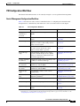
This chapter describes the different network topologies for the Cisco TV CDS, the different network
connections of the CDS servers, the CDS workflow, and network configuration considerations. The
topics covered in this chapter include:
•
Overview, page 2-1
•
TV CDS and VVI Topologies, page 2-2
•
CDS Workflow, page 2-7
•
Vault Virtualization, page 2-12
•
BMS Considerations for ISA Environments, page 2-17
•
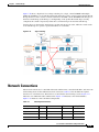
Network Connections, page 2-19
Overview
The TV CDS enables cable operators and multiple service operators (MSOs) to offer VOD and MediaX
services to consumer customers over their existing hybrid fiber coaxial (HFC) network, with existing
next-generation digital STBs. The TV CDS solution uses a gigabit Ethernet (GE) transport network from
the headend to the distribution hub, where the HFC network terminates.
TV CDS grows seamlessly from a single server implementation to multiple servers. As growth
continues, TV CDS allows operators to install distributed servers to address concentrations of
subscribers while leaving content ingest and management centralized.
Stream Groups can be distributed close to the subscriber and linked back to the central Vault locations
by way of the Cisco Cache Control Protocol (CCP). Cisco CCP automatically ensures that any new
content that is required by a customer edge device is transferred within a maximum of a 250-millisecond
delay to the appropriate edge location; as a result, all content appears local to each edge site, even though
most content is stored at the central Vault location.
The TV CDS offers different configurations with regards to network topology, business management
systems (BMSs), and streaming modes.
CDS with Vaults and Streamers
In a TV CDS with Vaults and Streamers, MPEG-2 transport stream (TS) video is stored on the Vaults
with the associated trick-mode files. Content is transported from the Vaults to the Streamers as needed,
by using CCP over gigabit Ethernet networks. Content is sent unicast from the Streamers and delivered
Cisco TV CDS 2.5 ISA Software Configuration Guide
OL-24788-01
2-1
Chapter 2
Network Design
TV CDS and VVI Topologies
to the quadrature amplitude modulation (QAM) devices over gigabit Ethernet or asynchronous serial
interface (ASI), and then is modulated onto the HFC plant to the subscriber set-top box (STB) for
viewing.
CDS with ISVs
For the smallest networks, Cisco packages the CDS in a single server, the Integrated Streamer-Vault
(ISV), offering a solution for VOD services with large content libraries but small stream counts.
In a TV CDS with ISVs, MPEG-2 TS video is stored on the ISVs with the associated trick-mode files.
Content is sent unicast from the ISVs and delivered to the QAM devices over a gigabit Ethernet network,
and then is modulated onto the HFC plant to the subscriber STB for viewing.
CDS with Caching Nodes
For larger networks, Cisco offers the CDS with Caching Nodes in the Virtual Video Infrastructure (VVI).
In a VVI, Caching Nodes are the intermediary fill source for Streamers, which removes a large portion
of the distribution traffic from the Vaults.
In a TV VVI, MPEG-2 TS video is stored on the Vaults with the associated trick-mode files. Content is
transported from the Vaults to the Caching Nodes as needed, by using CCP over gigabit Ethernet
networks. Content is distributed from the Caching Nodes to the Streamers as needed, by using CCP over
gigabit Ethernet networks, or by using HTTP over gigabit Ethernet networks. Content is sent unicast
from the Streamers and delivered to the QAM devices over a gigabit Ethernet network, and then is
modulated onto the HFC plant to the subscriber STB for viewing.
TV CDS and VVI Topologies
The TV CDS (using Vaults and Streamers, or ISVs) and the TV VVI (using Vaults, Caching Nodes, and
Streamers), supports centralized, decentralized, and hybrid gigabit Ethernet network designs. Because
the use of Vaults and Streamers separates storage from streaming, streaming requirements can be
satisfied on an as-needed basis and the streaming can be centralized or distributed among multiple
locations. Caching Nodes separate the ingest and storage of content from the distribution of content,
offering greater flexibility and network efficiency.
The TV CDS topology and TV VVI topology can change with the evolving needs of the system operator.
If the need to decentralize becomes evident, you can move the Streamers or Vaults to remote hubs
without disrupting service. The VVI offers additional flexibility in designing your network. Vaults can
be centrally located at a national network, and content may be classified by market (city, state, or a
broader region) depending on the AMS or BMS used. Caching Nodes can be located centrally, or
distributed closer to the regional networks where the Streamers are located. Using Caching Nodes in the
network design takes the distribution traffic off the network backbone.
Caution
All Cisco servers are connected through a switch. Because all Vaults, CCP Streamers, and Caching
Nodes in the same array exchange heartbeat messages through the cache interfaces, it is important to
ensure there is enough bandwidth among switches involved in delivering cache traffic, as well as to
support the same aggregated amount of traffic on all cache interfaces.
Cisco TV CDS 2.5 ISA Software Configuration Guide
2-2
OL-24788-01
Chapter 2
Network Design
TV CDS and VVI Topologies
Note
When using ISVs, with the Vault and Streamer functions contained in one server, the only topology
possible is centralized.
Centralized Topology
In a centralized topology, all CDS servers are located in either a single video headend or a remote hub.
This is the right solution for certain situations, for instance very small starting systems or where a large
amount of bandwidth is available. A centralized topology has advantages in reducing operational cost
by placing equipment in one physical location. Figure 2-1 illustrates the centralized topology for Vaults
and Streamers.
Figure 2-1
Centralized Topology with Vaults and Streamers
Headend or Remote Hub
Switch
Network
Switch
Network
GE QAMs
Streamers
203088
Vaults
HFC
Figure 2-2 illustrates the centralized topology for ISVs.
Figure 2-2
Centralized Topology with ISVs
Headend or Remote Hub
Switch
Network
GE QAMs
203089
ISVs
HFC
Cisco TV CDS 2.5 ISA Software Configuration Guide
OL-24788-01
2-3
Chapter 2
Network Design
TV CDS and VVI Topologies
Figure 2-3 illustrates the centralized topology for a VVI.
Figure 2-3
Centralized Topology with Caching Nodes
Headend or Remote Hub
Vaults
GE Switch
HFC
Caching Nodes
Streamers
252114
GE Switch
GE Switch
GE QAMs
Decentralized Topology
The decentralized topology is a hub-and-spoke topology between the headend site and multiple hub
sites, where the Vaults are located at the headend and the Streamers are in the hub sites. For a VVI, a
decentralized topology provides a three-tiered approach by having the Vaults located in the headend, the
Caching Nodes in intermediary sites, and the Streamers in the hub sites. The decentralized topology
works well for distributing Stream Groups close to subscribers. A decentralized topology has advantages
in reducing the amount of long-haul fiber transport bandwidth needed—typically by a factor of ten or
better. Figure 2-4 illustrates the decentralized topology.
Figure 2-4
Decentralized Topology
Remote Hub 1
Switch
Network
Streamers
Vaults
HFC
GE QAMs
Headend
Switch
Network
Remote Hub 2
Storage Content
Switch
Network
GE QAMs
203090
Streamers
HFC
Cisco TV CDS 2.5 ISA Software Configuration Guide
2-4
OL-24788-01
Chapter 2
Network Design
TV CDS and VVI Topologies
Figure 2-5 illustrates the decentralized topology with Caching Nodes.
Figure 2-5
Decentralized Topology with Caching Nodes
Tier Two
Caching Nodes
Remote Hub 1
GE QAMs
Streamers
GE Switch
GE Switch
Headend - Tier One
Vaults
HFC
GE Switch
Tier Two
Caching Nodes
Remote Hub 2
Streamers
GE QAMs
GE Switch
Storage Content
HFC
252115
GE Switch
Hybrid Topology
In a hybrid topology, the Vault servers and backup Streamer servers are located at the headend, with the
active Streamers at a remote hub site. If the remote hub site goes down, the Streamers at the headend
take over. A hybrid topology blends the advantages of centralized and decentralized topologies that is
based on needs of the system implemented. Figure 2-6 illustrates the hybrid topology.
Figure 2-6
Hybrid Topology
Remote Hub
Headend
Vaults
Switch
Network
Switch
Network
Streamers
Storage
Content
Switch
Network
HFC
GE QAMs
203091
Streamers
GE QAMs
Cisco TV CDS 2.5 ISA Software Configuration Guide
OL-24788-01
2-5
Chapter 2
Network Design
TV CDS and VVI Topologies
Figure 2-7 illustrates the hybrid topology with Caching Nodes.
Figure 2-7
Hybrid Topology with Caching Nodes
Remote Hub
Caching Nodes
GE Switch
GE QAMs
GE Switch
Headend
Vaults
Streamers
GE Switch
GE QAMs
HFC
252116
GE Switch
Streamers
TV VVI Management
The TV VVI offers two types of management, centralized and split-domain.
In a CDS, Streamers cannot communicate with Streamers in other groups. In a VVI, Streamers in other
groups can communicate with each other on an as-needed basis.
All Vaults, Streamers, and Caching Nodes are identified by an array ID, a group ID, and a server ID. In
the CDSM GUI, the array ID identifies servers that are part of the same system, the group ID identifies
servers that are part of the same group (Vault Group, Cache Group, and Stream Group), and the server
ID is a unique number that identifies the server. Table 2-1 lists the CDSM GUI ID names and maps them
to the CServer names in the setupfile and .arroyorc files.
Table 2-1
ID Names in the CDSM GUI and CServer Files
CDSM GUI ID Name
CServer Files ID Name
Array ID on the Array Name page
groupid
Group ID on the Server-Level pages
groupid
Stream Group ID on the Server Setup page
arrayid
Cache Group ID on the Server Setup page
arrayid
Vault Group ID on the Server Setup page
arrayid
Stream Group ID on the Configuration Generator page arrayid
Cisco TV CDS 2.5 ISA Software Configuration Guide
2-6
OL-24788-01
Chapter 2
Network Design
CDS Workflow
Centralized Management
Centralized management uses one Virtual Video Infrastructure Manager (VVIM) to manage the Vaults,
Caching Nodes, and Streamers in a VVI.
Split-Domain Management
Split-domain management uses one VVIM to manage the domain of Vaults and Caching Nodes, and
separate managers, the Stream Managers, to manage each domain of Streamers. The Stream Managers
communicate with the VVIM over port 80. If port 80 is not open for communication, the managers
cannot communicate with each other and configuration settings need to be uploaded to the Stream
Managers from information downloaded from the VVIM.
In a split-domain VVI that uses HTTP for communication between the Caching Nodes and Streamers,
the databases for each domain are separate. The information stored in each database is not shared with
the servers in the other domains.
In an ISA environment with a split-domain VVI that uses CCP for communication between the Caching
Nodes and Streamers, the database is replicated among all servers in the Vault/Cache domain and the
Stream domains. Because the VVI allows intercommunication among different Cache Groups and
Stream Groups when CCP Streamers are used, the server ID and group ID must be unique across the
system.
Note
Split-domain management is supported in an RTSP environment, and an ISA environment with the
Content Storage feature and CCP Streamers.
CDS Workflow
Content is ingested and stored in the Vault array. The Vault array can consist of two Vault Groups, which
in turn consists of two or more Vaults that are either colocated or distributed to multiple locations across
an Ethernet network. Content ingest is initiated by the backoffice based on a subscriber request, and
based on schedule or barker channel content. Manual ingest, which is operator initiated, is also offered
as an optional feature.
Note
The ability to differentiate between a DVD asset and a video asset to support ingest, trick-play creation,
and streaming of content files as large as 120 GB is supported. The content files could span multiple
days.
As the content is ingested into the Vault, any necessary trick-mode files are created. The content and
trick-mode files are then mirrored within the same Vault or across the Vault array. The replication of
content allows for data recovery should a Vault undergo a failure.
Content is delivered from the Vault array to the Stream Group in response to cache-fill calls from the
Streamers. Content is also distributed across the network in response to scheduled or barker stream
content fulfillment.
As Streamers need to fill content, they issue locate requests to the Vaults for the specific content. The
Streamer makes a decision on which Vault to pull content from based on the responses. The process of
determining where to pull content from includes memory capacity and disk capacity of the Vault, as well
as network capacity.
Cisco TV CDS 2.5 ISA Software Configuration Guide
OL-24788-01
2-7
Chapter 2
Network Design
CDS Workflow
If a VVI is deployed, content is delivered from the Vault Group to the Cache Group in response to
cache-fill calls from the Streamers. The Caching Nodes are explained in more detail in the “Caching
Node Workflow” section on page 2-10.
Within the Streamer array are one or more Stream Groups. The following section describes how the
Stream Groups deliver streams to the subscriber STBs.
Note
All servers can be on different subnetworks. However, because of backoffice restrictions, the
externalized IP address is constrained to migrate among servers on the same subnetwork. This means the
Content Store server in an Interactive Services Architecture (ISA) environment can migrate only among
Vaults that are on the same subnet, and the Setup and Control servers can migrate only among Streamers
on the same subnet.
Popularity-Based Caching
Popularity-based caching reduces the write rate to the storage devices on the Streamer and Caching Node
while maintaining the best possible cache-hit rate on the available storage.
To control peak and average write rates to cache (flash or disk storage), the algorithm that determines
when content is written to cache is changed so that only content that is likely to be accessed most often
is cached. Content is only cached if it is more popular than the least popular content that is currently
cached. Otherwise, the content is transmitted from the Vaults to the end-users by way of the cut-through
mode, where content is temporarily stored in the Streamer and Caching Node RAM without ever writing
it to disk or flash storage, and then streamed directly from the Streamer’s RAM to the end-user. When
cache space is needed, the least popular content is evicted from cache first.
The write rate for caching content is determined by the rate at which previously popular content becomes
less popular to the point where it no longer makes sense to keep it in cache, and previously unpopular
content becomes more popular to the point where it does make sense to keep it in cache. Content
popularity is measured by the time-decaying average of the number of play requests on each Global
Object Identifier (GOID).
Previously, all content was written to cache (except when overloaded) and the Least Recently Used
(LRU) content was evicted first.
With the Popularity-Based Caching feature, only popular content is written to cache and the least popular
content is evicted first.
Bandwidth Manager for Thin Pipe
The bandwidth manager controls the traffic leaving the site to any other site and queries all the CDS
servers in the site for the thin pipe mapping configuration of each CDS server. One server in the site is
elected as the bandwidth manager for all servers in the site. A site is defined by the Site Setup page,
which associates groups with a site. Initially, the bandwidth manager allocates bandwidths of whatever
the CDS servers have already committed, provided the committed bandwidths are within the pipe
bandwidth limits; otherwise, the bandwidth manager allocates a percentage of what is committed. After
the initial allocation, the bandwidth manager distributes the bandwidth equally among all the remaining
CDS servers in the site.
Each CDS server in each group reports the bandwidth each one is using to the bandwidth manager every
ten seconds. The bandwidth threshold for each server has an upper limit of 90 percent and a lower limit
of 5 percent. If a server reaches either limit, the server reports this to the bandwidth manager
Cisco TV CDS 2.5 ISA Software Configuration Guide
2-8
OL-24788-01
Chapter 2
Network Design
CDS Workflow
immediately, and does not wait for the ten-second report interval. For example, if the server is given 100
Mbps and the streams that were just started uses 90 Mbps, the upper threshold limit has been reached
and the server asks the bandwidth manager for more bandwidth.
A separate entry is maintained for each thin pipe with a list of servers that have the same thin pipe
configuration. Servers that belong to the same thin pipe are added and removed as they become reachable
or unreachable.
The bandwidth manager service runs on each server in either the primary mode or the passive mode. The
one server at the site that is running the primary mode is selected through a discovery mechanism. The
primary bandwidth manager maintains all the thin pipes and associated server structures. If the server
running the primary bandwidth manager fails or loses connectivity, the newly elected bandwidth
manager takes over and when the old primary bandwidth manager becomes available again and
connectivity is restored, the thin pipe information and structures are deleted from the old primary.
All bandwidth manager messages are logged in the bwm.log file. The following logging levels are
defined (default level is Information):
•
Critical
•
Error
•
Warning
•
Information
•
Debug
•
Debug Verbose
Streamer Workflow
A Stream Group is a configurable group of Streamers that are designated to serve specified QAM
devices, and subsequently, specific service groups. From a session setup and control perspective, there
are three logical types of servers in a Stream Group:
•
Setup server
•
Control server
•
Play server
The Setup and Control servers have both a primary and a backup server. The primary server services all
messages, while the backup server simply maintains states. If a primary server is unreachable, the
backup server takes over control and creates another backup server. Thus, there is always a primary and
backup pair of servers for setup and control. The Play server does not have a backup server. However,
the Control server selects a new Play server in the event of a failure of the existing Play server.
Note
The ability to have both a primary and backup server depends on the number of Streamers in the Stream
Group.
The Setup and Control server IP addresses are configurable. For an ISA environment, the Setup IP
address is the same as the Stream Master IP address. For RTSP, the Setup server and Control server must
be the same server. For both ISA and RTSP environments, the Stream Service selects a Streamer in the
Stream Group to be the Setup server, and another Streamer (sometimes the same Streamer) to be the
Control server.
Cisco TV CDS 2.5 ISA Software Configuration Guide
OL-24788-01
2-9
Chapter 2
Network Design
CDS Workflow
Setup Server
A Streamer designated as the Setup server interfaces with the backoffice and forwards the setup
messages to the appropriate Stream Group that is assigned to the destination service group. One
Streamer in the Stream Group that is colocated with the backoffice server is assigned as the primary
Setup server. The Setup server receives the setup request from the backoffice and maps the service group.
The Setup server returns the IP address of the Control server, and the STB issues subsequent control
messages to this IP address.
Control Server
The Control server assigns requests to specific Streamers and dynamically migrates streams between
Streamers based upon changes in stream states (for example, content splice boundaries, maintenance
trickle down, or server failures). One server in the Stream Group is assigned as the primary Control
server. The Control server runs the Lightweight Stream Control Protocol (LSCP) proxy in an ISA
environment and the Real-Time Streaming Protocol (RTSP) proxy in an RTSP environment.
For each and every setup message received from the backoffice, a CCP message is generated and sent to
the Control server. In the initial setup request, the Control server receives the setup parameters but does
not choose a Play server. After a control message is received from the STB, the Control server gets
performance information (for example, server load) from the potential Play servers within the Stream
Group and sends a CCP message to the best candidate. Subsequent control messages, whether from the
STB or from the Setup server, are forwarded to the chosen Play server.
Play Server
The Play server is the Streamer that is assigned to play the stream. This Streamer acquires the content,
whether in RAM, a local disk, or a Vault, and ensures guaranteed service delivery of the stream. Every
Streamer in a Stream Group is a possible candidate to be the Play server.
Caching Node Workflow
A Cache Group is a configurable group of Caching Nodes that serve content to specified Stream Groups.
When a content request is received by a Streamer, the Streamer first checks to see if the content is stored
locally, which includes DRAM, disk cache, and Streamers in the same Stream Group. Content on the
Streamers is always the most popular content, so user requests are generally served from local storage.
Streamers send cache-fill calls to remote servers for content that is not found locally. The remote servers
can be Streamers in other Stream Groups, Caching Nodes in Cache Groups, or Vaults in Vault Groups
(Vault Groups must be enabled). The cache-fill source selected, whether another Streamer, Caching
Node, or Vault, is based on the network capacity and fill-source capacity (disk and memory), as well as
on the preference configured for that group of servers. Caching Nodes could respond to the request with
a message stating the content is not currently cached, but there are other fill sources the Caching Nodes
can contact (Caching Nodes in other Cache groups, and Vaults).
The Caching Nodes use CCP to communicate with the Vaults, and use either CCP or HTTP to
communicate with Streamers.
Note
ISA environments support only CCP, while RTSP environments support only HTTP for VVI.
Cisco TV CDS 2.5 ISA Software Configuration Guide
2-10
OL-24788-01
Chapter 2
Network Design
CDS Workflow
HTTP Streamers
HTTP can be used for communication between the Caching Nodes and the Streamers. The HTTP
Streamer communicates with a proxy for locating a fill source and pulling content.
A locate service serves as a proxy for a group of Caching Nodes and Vaults. The service is accessed
through a highly available virtual IP address hosted by the Caching Node. The virtual IP address is bound
to a fill port (Locate Port).
HTTP Streamers request content by HTTP GET requests to the proxy service (the server with the locate
service). The proxy server checks its own storage and peer fill sources (servers in the same group) for
the content using extended-CCP. If the content is found, the best source is chosen based on capacity and
a redirect response is sent to the chosen server. If the content is not found, a cache-fill request is sent to
the remote servers.
After the best server is chosen to send the content to the HTTP Streamer, a single cache-fill port on that
server is chosen for the HTTP transfer of the content. This is different from CCP transfers, which could
potentially use all cache-fill ports to deliver the content.
HTTP Locate Port
With respect to resiliency, the Locate Port service is similar to the Setup and Control servers,. The
primary server of the Locate Port service has the locate port IP address bound to an interface. The backup
server becomes the primary if the primary fails.
Peer Caching Nodes advertise among themselves about the ability to host the HTTP Locate Port service;
this includes primary, backup, available, and not usable states. Available means the Caching Node can
be either a primary or backup if needed. Not usable means that the server cannot host the service; for the
HTTP Locate Port this typically means that there are no usable network ports for the service.
A dedicated network port on the Caching Node is used solely for the HTTP Locate Port service. The
primary server determines service availability based on the link status of the dedicated network port.
Failover of the service occurs if the network port loses link status. A reestablished link results in the
server becoming available.
CCP Streamers
The CCP Streamers use CCP to communicate with the Caching Nodes. They do not use the proxy
address. CCP Streamers load-balance locate requests across fill sources.
The Streamer or Caching Node sends a locate-and-request message from the proxy server. The Proxy
server sends a message to the best source to fill the request.
Streamers or Caching Nodes needing content first query peer sources (servers within the same group).
Streamers also query local Streamers, if the content is not found, then a request to the remote sources is
sent. Remote sources are queried based on a preference list. Sources are grouped and preferences are
assigned for each group.
Vault Workflow
The Vaults ingest content using three different methods:
•
FTP pull
•
FTP push
•
Live capture of MPEG-2 transport streams over UDP
Cisco TV CDS 2.5 ISA Software Configuration Guide
OL-24788-01
2-11
Chapter 2
Network Design
Vault Virtualization
With FTP pull, the original content is kept on an FTP server (catcher), for a period of time and
mechanisms are in place to restart ingests until they have successfully completed.
With FTP push, only a window of data is buffered by a device that grooms the live (broadcast) feed and
pushes the data to the Vault.
With live capture over UDP, the Vault captures the live multicast feed directly.
Vault Virtualization
Vault Virtualization provides the following three types of configuration:
Note
•
ISA Regionalization
•
Shared Content Store
•
Virtual Content Store
Virtual Content Store provides enhanced features to Shared Content Store.
ISA Regionalization
The ISA Regionalization feature is a combination of the Virtual Video Infrastructure (VVI) and legacy
Content Delivery System (CDS). This feature provides the ability to centrally store content on Vaults
located in a centralized storage facility and allow remote sites to have a record of inventory of this
content and access it by way of the Caching Nodes or directly on the central Vaults. The remote sites
still operate as independent entities with their own local Vault Group, local Content Store, and local
Streamers; managed by their own CDSMs and possibly accessing their own local BMS and AMS. The
Streamers at each remote site can stream both locally stored content and centrally stored content.
The ISA Regionalization feature allows the use of a centralized storage facility containing both Vaults
and Caching Nodes in a Virtual Video Infrastructure (VVI), while maintaining a localized or remote
CDS at each headend.
For information on configuring ISA Regionalization, see the “ISA Regionalization Configuration
Workflow” section on page 3-9.
Centralized Storage
The Virtual Video Infrastructure Manager (VVIM) manages the Vaults and Caching Nodes allocated in
the centralized domain. The centralized domain can be distributed across multiple geographic locations;
for example, the Vaults could be located in one location and the Caching Nodes could be located in
another. The VVIM typically resides in one of these locations.
Each CDS has a virtual view of the VOD content stored on the central Vaults. The centralized content is
ingested once, the first time it is requested; any subsequent ingest requests for that same content
increments a reference counter.
Cisco TV CDS 2.5 ISA Software Configuration Guide
2-12
OL-24788-01
Chapter 2
Network Design
Vault Virtualization
Remote Site
Each remote CDS has a local Vault Group and communicates with a local BMS and local AMS located
at the headend or at another headend nearby. Each remote CDS is able to ingest local content through
the local Vaults and is able to access content stored in the central storage facility by way of the Caching
Nodes and Vaults in the VVI. The centrally stored content is abstracted from the BMS by means of the
local Content Store providing a virtual view of that content to the BMS. Both local and central content
are available to fulfill streaming requests received by the Streamers in a remote CDS.
The ISA Regionalization feature uses the existing ISA architecture, but extends the ISA content
component to support new behaviors associated with where content is physically located. Each CDS
operates with a local ISA Content Store, which is extended to manage both centrally and locally stored
content.
Real-time asset (RTA) content is not centralized, and is stored on local Vaults in each headend. The CDS
determines if content should be ingested centrally or locally based upon on the type of content (VOD or
RTA) that is being requested.
Note
If the local Vaults are not available because they are down or have lost connectivity, then the master
Streamer in the headend automatically takes over as the Ingest Driver client. If this occurs, when the
local Vaults have been recovered and regained connectivity, the Ingest Driver client must be migrated
back to the local Vaults before RTA ingests can be restored.
To move the Ingest Driver client from the master Streamer back to the local Vaults, stop and restart the
statsd process on the master Streamer by entering the following commands:
pkill statsd
/home/stats/statsd -i <server_mgmt_IP_addr> -s <subnet mask> -d eth0
Ingest Driver
The ISA Regionalization feature introduces the Ingest Driver, which has a server-side and a client-side.
The Ingest Driver server is located at the central location, on the master Vault, and is responsible for
managing the content ingestion and deletion requests from the Ingest Driver clients located at the remote
sites.
Ingest Driver Server
The centralized Vaults run an internal Naming Service, Notification Service, and Content Store. This
Content Store is not associated with a remote BMS, and acts independently of all remote sites. The
Ingest Driver gets the Content Store factory from the internal Naming Service, ingests content using the
createServant and provision methods, and deletes content using destroy and removeServant.
The Ingest Driver server is started and stopped on the master Vault and is automatically restarted like
other ISA processes. When the server is started, it binds to a TCP socket and waits for requests. To
handle the requests quickly, there are several threads created to parse the requests and fulfill them. When
the server processes the request for each content, only one request is handled; that is, other simultaneous
requests for the same content are blocked.
The Ingest Driver server reads the isa.cfg file and incorporates the following Ingest Driver configuration
parameters set on the CDSM GUI:
•
IngestDriverEnabled=1
•
IngestDriverRole=1 (for server)
Cisco TV CDS 2.5 ISA Software Configuration Guide
OL-24788-01
2-13
Chapter 2
Network Design
Vault Virtualization
•
IngestDriverHost
•
IngestDriverPort
•
IngestDriverNoOfThreads
The Ingest Driver server logs events to the IngestDriver.log file located in the /arroyo/log directory.
Ingest Driver Client
The Ingest Driver client is used by the local Content Store to send requests to the Ingest Driver server
and receive responses from the server. When a provision call from the local Content Store is received
from the backoffice, the Ingest Driver client establishes a TCP connection with the Ingest Driver server,
sends the request, and closes the connection once the response is received.
The local Content Store reads the isa.cfg file and incorporates the following Ingest Driver configuration
parameters for the Ingest Driver client set on the CDSM GUI:
•
IngestDriverEnabled=1
•
IngestDriverRole=0 (for client)
•
IngestDriverHost
•
IngestDriverPOrt
•
IngestDriverTimeout
•
MarketId
Ingest Driver Content Management
The local Content Stores at the remote sites perform content management of the content at the central
facility by interfacing with the Ingest Driver. The Ingest Driver compares the requested content identifier
of each content ingestion and deletion request to the CDS repository to determine if the content exists.
If the content does not exist, it is ingested using FTP and the FTP URL provided by the remote site. If
the content already exists, the repository is updated to maintain the reference between the requesting site
and the content. The Ingest Driver returns the CDS internal representation of the content bundle and
associated content information, such as file size and bit rate.
When the Ingest Driver receives a deletion request, it determines if the request is for the last reference
to the content. If it is the last reference, the Ingest Driver requests that the central Content Store delete
the content and associated MPEG files. If it is not the last reference for the content, the Ingest Driver
just removes the reference of the requesting site for that content in the repository.
Remote Ingests
At each headend, the external ISA interfaces to the backoffice do not change, and call flows remain the
same. The remote CDSM is extended to identify a site as part of a regionalization grouping, and specify
the communication information of the Ingest Driver. Internally, the local Content Store application is
modified to check for this setting. If regionalization is turned on, the local Content Store application
directs VOD (provision) requests to the Ingest Driver and RTA (provisionForPush) requests are directed
to the local Vaults.
The local Content Store performs the createServant call locally, thus ensuring that each remote site has
its own IOR representing the content object. If the request is distributed, the local repository is updated
with the content-specific information, such as the content bundle, file size, and bit rate returned by the
Ingest Driver. This allows the remote site to have local representation of centrally stored content.
Cisco TV CDS 2.5 ISA Software Configuration Guide
2-14
OL-24788-01
Chapter 2
Network Design
Vault Virtualization
For RTA content, the process is same as it has always been for the CDS. The local Content Store
processes the provision call (provisionForPush for RTA) and directs the local Vaults to perform the
ingest of the content.
Remote Streaming
Local streaming is accomplished by way of the Cache Control Protocol (CCP) locate capability. Each
remote site is configured to communicate to a specific set of storage devices which could include local
Vaults, central Vaults, and Caching Nodes. The locate feature broadcasts a request for a specific content,
and the system performs a cost analysis to determine which storage device can best provide service. For
VOD content, if the content is not already cached on the local Streamers, it is acquired from either the
central Vaults or Caching Nodes. For RTA content, if the content is not cached on the Streamers, it is
acquired from the local Vaults. However, knowledge of the content type is not required as the locate
capability is able to determine its location.
Shared Content Store
Shared Content Storage, also known as Shared Content Store (SCS), works with a single, centralized
AMS and catcher, through which all initiation for content ingest and content deletion is sent. The SCS
handles ingest and deletion requests from multiple backoffices by way of the central AMS. The scenario
of backoffices independently ingesting and deleting content through their local AMS is not supported.
Note
The Content Storage feature requires the Virtual Video Infrastructure feature with Caching Nodes.
Figure 2-8 shows a high-level view of the SCS and a single, centralized AMS for multiple video hub
offices (VHOs). A VHO is a local deployment that includes the video backoffice, Streamers, application
servers, QAM devices, and other headend equipment.
Figure 2-8
Shared Content Store For Multiple Video Headends
VHO 1
Vault Array with Shared
Content Store
Shared
Content Store
CServer
Stream
Service
MPEG-2 TS
MPEG-2 TS
CServer
MPEG-2 TS
Streamer Array
Naming
Service
Video
Backoffice
FTP
Shared DNS
Server
VHO 2
Catcher
Stream
Service
Legend
Data / Video Plane
DNS Access
CServer
Streamer Array
Video
Naming
Backoffice
Service
MPEG-2 TS
203530
FTP
Asset
Management
System
Cisco TV CDS 2.5 ISA Software Configuration Guide
OL-24788-01
2-15
Chapter 2
Network Design
Vault Virtualization
The DNS server typically runs on the BMS server. The Naming Service is part of the video backoffice
(VBO). All CORBA components, including the AMS, Stream Service, and Content Store, need to
register with the Naming Service. The catcher receives or “catches” new content assets from an external
communication device such as a satellite transmission or FTP server. After the package is received
completely by the catcher, it sends the package by way of FTP to the AMS. The package consists of video
and image content assets, as well as ADI metadata.
Following are the requirements for the SCS feature:
•
Single, shared DNS server with all devices registering their hostnames to it. A central, shared DNS
is required to resolve multiple Naming Services belonging to the different VHOs.
•
Hostnames must be unique for all devices. This is required for the Naming Service discovery.
•
Each VHO has its own Naming Service to which the ISA components of the VHO register.
•
AMS controls the ingest and deletion of content.
•
The Vault array has one SCS.
•
SCS registers with each Naming Service.
A VVI with SCS must be initialized in the following order:
1.
The shared DNS server must be up and running before starting up the shared AMS, SCS, and VHO
devices.
2.
SCS successfully registers with the Naming Service for each VBO.
3.
Each VHO Stream Service registers with its respective Naming Service.
Ingesting Content with the Shared Content Store
Upon receiving the content package, the AMS schedules it for ingest by informing the Package Factory
in each participating VBO of the content package, and passing the pertinent information (the ADI
metadata, the URL where the content package can be accessed in the AMS, and the verb ingest).
The SCS creates one interoperable object reference (IOR) for each content package. The IOR is returned
to all VBO Package Factories that request it, including any that requested it at the time the IOR was being
created.
Deleting Content with the Shared Content Store
To delete content that was ingested for more than one VBO, the AMS is used to send the export package
delete request to each VBO. The content is deleted from the Vault array only when all VBOs have
requested the deletion. If one or more VBOs have not requested that the content be deleted, the content
remains in the Vault array.
Virtual Content Store
The Virtual Content Store feature in an ISA environment replaces the Shared Content Store feature
introduced in Release 2.1. The Shared Content Store (SCS) feature is the ability of several local sites
(video hub offices [VHOs]) to ingest content at a central location and share that content with the other
VHOs. The SCS feature eliminated ingesting multiple copies of the same content.
Release 2.2 and later releases offered Multi-Screen Video (MSV) support for ISA environments
configured with SCS. An MSV Asset Deletion script ran nightly by default. The script identified the
VOD assets that were removed by the backoffice and deleted them from the Vaults. If the asset was found
in any one of the VHOs, the asset was not deleted. Only when the asset was not found in all VHOs was
the asset deleted from the Vaults.
Cisco TV CDS 2.5 ISA Software Configuration Guide
2-16
OL-24788-01
Chapter 2
Network Design
BMS Considerations for ISA Environments
In Release 2.5.2, Vault Virtualization replaces the SCS with the Virtual Content Store (VCS). No content
is ingested at the local VHO. All ingests and deletions of content occur at the central location, and both
ingests and deletions are initiated by the local BMS at each local VHO, just as they were in the SCS.
However, the VHOs do not need to communicate with the super headend (SHE) as they did with the SCS
feature. With VCS, communication of ingestions and deletions is handled by the Ingest Driver client
residing on a Streamer in each VHO and the Ingest Driver server residing on the master Vault in the SHE.
Vault Virtualization requires that Vault Groups be disabled.
The Virtual Content Store (VCS) component runs on a Streamer in the Stream Group, and if a failover
occurs, the VCS fails over to another Streamer in the Stream Group.
Only one copy of the centrally located asset is ingested and shared by the system, and the asset is only
deleted when all VHOs have requested the deletion.
With the VCS, the MSV Asset Deletion script is no longer needed and is removed during the software
upgrade to Release 2.5.2.
For information on configuring Virtual Content Store, see the “Virtual Content Store Configuration
Workflow” section on page 3-10.
BMS Considerations for ISA Environments
The TV CDS integrates with Interactive Services Architecture (ISA) used in business management
systems (BMSs) such as the Tandberg OpenStream and the RTSP used in BMSs such as ARRIS nABLE,
as well as in environments that are a combination of both ISA and RTSP. The BMS determines the roles
and responsibilities of the TV CDS.
OpenStream ISA Integration
The OpenStream BMS is built on Common Object Request Broker Architecture (CORBA) and provides
naming and notification services. The Naming Service allows the TV CDS to locate objects in the system
such as content, equipment, assets, and so on. The Notification Service allows the TV CDS to listen for
important events in the system as well as to send events to the OpenStream BMS and other components
in the system.
Note
Dual conditional access systems (CAS) for ISA environments, Cisco/Scientific Atlanta Power Key
Encryption System (PKES) and the Motorola OffLine Encryption Station (OLES), is supported. A field
on the Monitor Completed Ingests page indicates whether the ingested content is encrypted or not. Both
clear and encrypted content can be ingested.
For more information on the configuration parameters required to facilitate communication between the
OpenStream BMS and the TV CDS, see Appendix C, “BMS Communication.”
Figure 2-9 illustrates how the TV CDS integrates with the OpenStream BMS.
Cisco TV CDS 2.5 ISA Software Configuration Guide
OL-24788-01
2-17
Chapter 2
Network Design
BMS Considerations for ISA Environments
Figure 2-9
TV CDS Integration into the OpenStream BMS
Streaming Mode
OpenStream uses a session-based approach to handle resource requirements and allocation. In the course
of setting up a session, a QAM device is specified that has available capacity and connectivity to the
Streamer and the STB requesting the service. Typically, the Session and Resource Manager (SRM) is
responsible for the allocation of network resources. OpenStream uses the Digital Storage
Media-Command and Control (DSM-CC) session management protocol to request resources from the
SRM.
When using gigabit Ethernet for streaming, OpenStream communicates with the SRM to negotiate
network resources and allocation for sessions.
When using Asynchronous Serial Interface (ASI) for streaming, the Streamer performs the role of the
SRM by managing and allocating the access network resources and providing this information to the
OpenStream BMS.
Steering Ingests
The Ingest Steering feature offers the ability to have one BMS send ingest information to the master
Vault, and depending on the product ID in the content name, the content is either ingested by one of the
Vaults in the national Vault Groups, or it is ingested by a specific local Vault Group.
Note
For the Ingest Steering to function correctly, the content name must be in the following format:
ProviderId::AssetId::contentName.
The Ingest Steering feature requires that VVI with central management and Vault Groups be enabled.
Cisco TV CDS 2.5 ISA Software Configuration Guide
2-18
OL-24788-01
Chapter 2
Network Design
Network Connections
Figure 2-10 shows a high-level view of Ingest Steering for a single, centralized BMS and multiple
VHOs. Each VHO has a local Vault Group through which all local live content is ingested. Each Stream
Group streams local live content as well as national live and VOD content. The BMS sends messages to
the master Vault Group (Vault Group 1), and depending on the product ID and the ingest steering
configured, the content is ingested by either the local Vault Group or the national Vault Group.
Content objects on the national Vault Groups are mirrored among each other, while the content on the
local Vault Groups are copied to separate hard drives on each Vault.
Figure 2-10
Ingest Steering
Network Connections
The network connections for a TV CDS with Vaults and Streamers, a TV CDS with ISVs, and a TV VVI
with Caching Nodes all have different network connections. Table 2-2 lists the different required
interfaces for each CDS server. The interfaces are described in the following sections. Figure 2-11
illustrates a TV CDS with Vaults and Streamers. Figure 2-12 illustrates a TV CDS with ISVs.
Figure 2-13 illustrates a TV VVI with Caching Nodes.
Table 2-2
CDS Required Interfaces
Interface
Vault
Streamer
ISV
Caching Node
Management
1
1
1
1
Ingest
1
—
1
Cache
1 to 8
1 to 13
1 to 4
Stream
—
1 to 13
1 to 4
—
1
1 to 12
—
Cisco TV CDS 2.5 ISA Software Configuration Guide
OL-24788-01
2-19
Chapter 2
Network Design
Network Connections
1. The cache interfaces on an ISV are used for content mirroring among ISVs.
Note
Table 2-2 lists the mandatory interfaces for each CDS server. If HTTP Streamers are used in a VVI, each
Caching Node must have one interface designated as the Locate interface. Stream Control is an optional
interface function. For more information, see the “Configuring the Interfaces” section on page 4-109.
Figure 2-11 shows the different logical networks of a CDS consisting of Vaults and Streamers. The
ingest network receives content from the content source by way of an FTP staging server or FTP catcher
and the content is ingested by the Vaults. The management network consists of communication between
the CDSM and the BMS, as well as communication with the Vaults, Streamers QAM devices, and STBs.
The cache network consists of Vaults and Streamers.
Figure 2-11
Vault and Streamer Network Connections
Figure 2-12 shows the different logical networks of a CDS consisting of ISVs. The ingest network
receives content from the content source by way of an FTP staging server or FTP catcher and the content
is ingested by the ISVs. The management network consists of communication between the CDSM and
BMS, as well as communication with the ISVs, QAM devices, and STBs.
Cisco TV CDS 2.5 ISA Software Configuration Guide
2-20
OL-24788-01
Chapter 2
Network Design
Network Connections
Figure 2-12
ISV Network Connections
Cisco TV CDS 2.5 ISA Software Configuration Guide
OL-24788-01
2-21
Chapter 2
Network Design
Network Connections
Figure 2-13 shows the different logical networks of a VVI. The ingest network receives content from the
content source by way of an FTP staging server or FTP catcher where it is ingested by the Vaults. The
management network consists of communication between the CDSM and BMS, as well as
communication with the Vaults, Streamers, Caching Nodes, QAM devices, and STBs.
Figure 2-13
VVI Network Connections
Content Commands to and
from Vaults
Session Command to and
from Streamer
BMS information
BMS
BMS information
mgmt
FTP
Staging
Server
Cache
Network
Vault
Stream
Group
Caching
Node
Ingest
Network
mgmt
S
w
i
t
c
h
Cable STB
Vault
Caching
Node
Catcher
FTP
HFC
Network
QAM
Device
mgmt
BMS information
C
F
E
Caching
Node
mgmt
Vault
Cache
Network
mgmt
ingest
Vault
Caching
Node
Stream
Group
S
w
i
t
c
h
QAM
Device
OOB BMS Messages
Ingest
Content
Source
C
F
E
mgmt
HFC
Network
Layer 2/3:
QAM:
QPSK:
203528
Mgmt
Network
mgmt
OOB BMS Messages
Cable STB
Ingest Interface
The ingest interface takes in FTP traffic from the content provider at a maximum rate of one gigabit per
second. After the Vault server receives URL information about the content from the BMS by using the
management interface, the ingest interface either (1) receives FTP traffic by acting as an FTP client, or
(2) receives live data upon receiving a request to act as the FTP server.
When using Layer 2 packet forwarding, to segregate all ingest traffic through the switching fabric, we
recommend the use of a port-based VLAN.
Cisco TV CDS 2.5 ISA Software Configuration Guide
2-22
OL-24788-01
Chapter 2
Network Design
Network Connections
Management Interface
The management interface communicates with the network management system (NMS) by way of
SNMP, the BMS by way of ISA commands and also RTSP, and with all Vaults, Caching Nodes, and
Streamers in the same array. Information shared among servers in the same array includes the following:
•
Host service information
•
Domain Name System (DNS) service information
•
QAM gateway information
•
All ISA information
Management traffic is low volume; however, when using Layer 2 packet forwarding, we recommend
using a port-based VLAN to ensure delivery of critical management communications.
Cache Interfaces
The CCP uses the cache interfaces on the Vaults, Caching Nodes, and Streamers to send the following
data to the servers in the same array:
Note
•
Content sent to the Streamers
•
Content mirrored among the Vaults
•
Messages containing information used for performance optimization exchanged among all the CDS
servers
All Cisco CDS servers are connected through a switch fabric. Because all Vaults, Caching Nodes, and
Streamers in the same array exchange heartbeat messages through the cache interfaces, it is important to
ensure there is enough bandwidth among switches involved in delivering cache traffic and to support the
same aggregated amount of traffic on all cache interfaces.
When using Layer 2 packet forwarding for cache traffic, we recommend the use of a port-based VLAN.
Cache/Stream Interfaces
The cache/stream interfaces on the Streamer server can be used for both cache and streaming traffic. The
number of interfaces designated for each traffic type is configurable. If an interface is configured for
both cache and streaming traffic, priority is given to the higher-bandwidth stream traffic provided cache
traffic is able to transmit on other interfaces.
When using Layer 2 packet forwarding for cache and stream traffic, we recommend the use of a
port-based VLAN.
Streaming Interface
The streaming interface delivers streaming traffic consisting of MPEG-2 transport streams to STBs by
way of QAM devices.
If an interface is configured for both stream and cache traffic, and the jumbo frames feature is not
enabled for stream traffic while jumbo frames is enabled for cache traffic, stream traffic uses 1500-byte
packets while cache traffic uses jumbo frames.
Cisco TV CDS 2.5 ISA Software Configuration Guide
OL-24788-01
2-23
Chapter 2
Network Design
Network Connections
Cisco TV CDS 2.5 ISA Software Configuration Guide
2-24
OL-24788-01
CH A P T E R
3
Getting Started
This chapter provides information on configuring the TV CDS servers. The topics covered in this chapter
include:
•
Initially Configuring the Devices, page 3-1
•
Logging In to the TV CDSM, page 3-1
•
Initializing the CDS and Activating the Optional Features, page 3-3
•
Navigating the CDSM, page 3-4
•
Configuration Workflows, page 3-5
This chapter assumes the CDS servers are already installed and takes you through the next steps toward
configuring and monitoring the CDS.
Initially Configuring the Devices
You must initially configure the Content Delivery Engines (CDEs) before they can participate in the CDS
network. The CDE that runs the TV Content Delivery System Manager (CDSM) must be initialized first
so that the CDEs running the Streamers, Vaults, and optionally Caching Nodes, or the ISVs can
communicate with it. For more information about initially configuring the CDEs, see the Cisco Content
Delivery Engine 205/220/250/420 Hardware Installation Guide, the Cisco Content Delivery Engine 110
Hardware Installation Guide, or the Cisco TV CDS 2.5 Installation, Upgrade, and Maintenance Guide.
Initial configuration of your CDEs includes basic network configuration settings to provide connectivity
to the CDSM. After the CDEs are configured with these settings you can use the CDSM to configure and
manage all the servers in the CDS.
After you have initially configured your CDEs, you must initially set up your CDS and activate any
optional features. See the “Initializing the CDS and Activating the Optional Features” section on
page 3-3 for more information.
Logging In to the TV CDSM
To log in to the TV CDSM, do the following:
Step 1
Using your web browser, enter the IP address or hostname of your CDSM.
For example, if the IP address of your CDSM is 192.168.0.236, you can access it by entering
http://192.168.0.236 in the address or location text box of your browser program.
Cisco TV CDS 2.5 ISA Software Configuration Guide
OL-24788-01
3-1
Chapter 3
Getting Started
Logging In to the TV CDSM
Note
Consult your as-built documentation for the IP address of the CDSM. If you have redundant
CDSMs, use the virtual IP address, not the IP addresses of the physical Ethernet interfaces.
The CDSM GUI now supports HyperText Transport Protocol Secure (HTTPS) as a secure way to access
the browser-based interface. The cdsconfig script offers the following choices to access the CDSM GUI:
•
HTTP
•
HTTPS
•
HTTP and HTTPS
The System Login page is displayed, as shown in Figure 3-1.
Figure 3-1
Note
Step 2
System Login Page
The CDSM supports Microsoft Internet Explorer version 6 or higher.
Enter your user name and password and click Log In.
The built-in user name is admin and the initial password is admin.
Note
Tip
We strongly recommend that you change the built-in user password as soon as possible. See the
“Editing User Settings” section on page 7-5 for more information.
To navigate within the CDSM, click one of the navigation bar options (for example, Maintain), then one
of the tab options (for example, Users), and then one of the left-panel menu options (for example, Add
Users). Navigational directions in procedures are written as in the following example:
Choose Maintain > Users > Add Users.
Cisco TV CDS 2.5 ISA Software Configuration Guide
3-2
OL-24788-01
Chapter 3
Getting Started
Initializing the CDS and Activating the Optional Features
Logging Out
To log out of the CDSM from any page, click Logout at the upper-right part of the page. See Figure 3-2.
Figure 3-2
Logging Out
Initializing the CDS and Activating the Optional Features
Initial configuration of your CDS includes selecting the CServer version, the installation type, and other
parameters that must be configured before you can continue the configuration process.
If the Media Scheduler or Ingest Manager are part of your deployment, you need to activate these
features by entering an activation key.
To initialize your CDS or activate the Media Scheduler and Ingest Manager, do the following:
Step 1
Log in to the CDSM as admin, or use another user account that has master access.
Step 2
Add a user with engineering access.
a.
Choose Maintain > User > Add Users. The Add Users page is displayed.
b.
In the New User and Password fields, enter the user name and password for this account.
c.
From the Access drop-down list, choose Engineering.
d.
Click Add User.
Step 3
Log out of the CDSM, and log in as the user with the Engineering access level that you specified in
Step 2. The CDSM Setup page is displayed.
Step 4
Choose the options for your deployment and click Submit. For more information about the fields on this
page, see the “CDSM or VVIM Setup” section on page F-3.
Step 5
To activate the Media Scheduler, scroll down to the Media Scheduler section, and click the ON radio
button next to the Media Scheduler field.
Step 6
a.
In the Activation Key field, enter the software access key from your Right to Use Notification for
the Content Delivery Application Media Scheduler (CDAMS) product.
b.
In the Importer/Transformer Type field, choose either OCN or SA Tribune. The
Importer/Transformer Type specifies the expected EPG format, the fields for the Input Channels
page, and the expected ADI metadata.
To activate the Ingest Manager, scroll down to the Ingest Manager section, and click the ON radio button
next to the Ingest Manager field.
a.
In the Activation Key field, enter the software access key from your Right to Use Notification for
the Content Delivery Application Stream Resiliency, VOD ER for Gen 1 & Gen 2 Streamers
(CDATSTR2-EN) product or for the Content Delivery Application Stream Resiliency, VOD ER for
Gen 3 Streamers (CDATSTR3-EN) product.
Cisco TV CDS 2.5 ISA Software Configuration Guide
OL-24788-01
3-3
Chapter 3
Getting Started
Navigating the CDSM
Step 7
To activate the VOD Error Repair, scroll down to the VOD Error Repair section, and click the Enabled
radio button next to the VOD Error Repair field.
a.
In the Activation Key field, enter the software access key from your Right to Use Notification for
the Content Delivery Application VOD Error Repair (CDAVER) product.
Step 8
Click Submit.
Step 9
Log out of the CDSM.
Navigating the CDSM
The CDSM pages consist of the elements illustrated in Figure 3-3.
Figure 3-3
CDSM User Interface
2
3
4
5
6
251355
1
1
Left panel menu
4
Page title
2
Tabs
5
Main panel
3
Tab options
6
Tools (Home, Help, and, Logout)
The tabs are accessible from any page in the CDSM.
The tab options are used to choose the applicable level. In the Configure and Monitor pages, the tab
option selected determines whether the configuration or monitoring applies to the system as a whole, to
the array level, or to a specific server.
Cisco TV CDS 2.5 ISA Software Configuration Guide
3-4
OL-24788-01
Chapter 3
Getting Started
Configuration Workflows
Using Online Help
Online help is available in the CDSM. You can use it by clicking on the Help button in the upper-right
corner of any of the pages.
Context-sensitive help is provided for the page you are viewing.
The CDSM offers several levels of help:
•
Each page of the CDSM includes some basic help, normally displayed in the main panel.
•
The Help button displays context-sensitive help presented in a separate browser window. The
content of this page is different depending on the page of the CDSM you are viewing when you click
Help. After inside the help system you can move around to view different topics by using a variety
of navigation tools:
– Back/forward page buttons
– Links within the page contents
– Table of Contents, accessed through the navigation panel at the left of the page.
– Contents icon shows and hides the Table of Contents.
– Print icon prints the page you are viewing.
•
From the Help window, you can display the full Cisco TV CDS 2.5 ISA Software Configuration
Guide by clicking the View PDF button.
Configuration Workflows
After you have completed the initial installation and configuration of the CDEs for the CDS and you have
verified connectivity to the CDSM, you are ready to configure the CDS for content delivery. The
configuration workflow consists of one ore more of the following:
•
CDS Configuration Workflow
•
VVI Configuration Workflow
•
Vault Virtualization Configuration Workflow
•
TV MediaX Configuration Workflow
•
TV Playout Configuration Workflow
Cisco TV CDS 2.5 ISA Software Configuration Guide
OL-24788-01
3-5
Chapter 3
Getting Started
Configuration Workflows
CDS Configuration Workflow
Table 3-1 lists the basic tasks, in the recommended order, for configuring the CDS for content delivery
with references to the associated sections in each chapter.
Table 3-1
Configuration Workflow
Task
Description
Where to Find More Information
Change
administrator
password
Change the administrator password for the
CDSM.
Editing User Settings, page 7-5
Interface setup
Configure the different interfaces on the CDS
servers.
Configuring the Interfaces,
page 4-109
Server setup
Configure the IP addresses and ports for the
interfaces, as well as other settings such as
quality of service (QoS).
Configuring the Servers,
page 4-112
Route table
Route Table identifies destination subnetworks Configuring the Route Table,
for cache, stream, and stream control
page 4-118
interfaces. Route Table is optional.
Stream groups
setup
A Stream Group consists of one or more
Streamers. Stream Groups relate to QAM
gateways or destination subnetwork by the
Stream Group preference.
Configuring Stream Groups,
page 4-58
Control and setup
IPs
Configure the Control server and Setup server
IP address for the Stream Groups.
Configuring the Control and
Setup IPs, page 4-72
BMS settings for
the Streamers
Configure the settings for the Streamers to
communicate with the BMS.
Configuring the Streamer for
BMS Connectivity, page 4-45
BMS settings for
the Vaults
Configure the settings for the Vaults to
communicate with the BMS.
Configuring the Vault for BMS
Connectivity, page 4-50
QAM gateways1
Configure the QAM Gateways for the CDS.
Configuring QAM Gateways,
page 4-4
Headend setup1
Configure service groups for gigabit Ethernet
streaming, ASI streaming, and barker streams.
Configuring the Headend Setup,
page 4-9
Ingest tuning
Configure the trick-mode speeds for ingested
content.
Configuring Ingest Tuning,
page 4-26
1. If the Stream Destination feature is set to IPTV, the QAM Gateway page and Headend Setup page are replaced with the Stream
Destination page. A setting of Mixed for Stream Destination displays all three pages, For more information, see the
“Configuring Stream Destinations” section on page 4-17.
The other configuration settings, barker streams, parent/child service groups, DNS settings, and so on,
can be configured in any order.
Cisco TV CDS 2.5 ISA Software Configuration Guide
3-6
OL-24788-01
Chapter 3
Getting Started
Configuration Workflows
VVI Configuration Workflow
The Virtual Video Infrastructure can be centrally managed or can use split-domain management.
Central Management Configuration Workflow
Table 3-2 lists the basic tasks, in the recommended order, for configuring the VVI with central
management for content delivery with references to the associated sections in each chapter.
Table 3-2
VVI Configuration Workflow
Task
Description
Where to Find More Information
Change
administrator
password
Change the administrator password for the
CDSM.
Editing User Settings, page 7-5
Interface setup
Configure the different interfaces on the CDS
servers.
Configuring the Interfaces,
page 4-109
Server setup
Configure the IP addresses and ports for the
interfaces, as well as other settings such as
quality of service (QoS).
Configuring the Servers,
page 4-112
Route table
Route Table identifies destination subnetworks Configuring the Route Table,
for cache, stream, and stream control
page 4-118
interfaces. Route Table is optional.
Stream Groups
setup
A Stream Group consists of one or more
Streamers. Stream Groups relate to QAM
gateways or destination subnetwork by the
Stream Group preference.
Configuring Stream Groups,
page 4-58
Control and Setup
IP addresses
Configure the Control server and Setup server
IP address for the Stream Groups.
Configuring the Control and
Setup IPs, page 4-72
BMS settings for
the Streamers
Configure the settings for the Streamers to
communicate with the BMS.
Configuring the Streamer for
BMS Connectivity, page 4-45
BMS settings for
the Vaults
Configure the settings for the Vaults to
communicate with the BMS.
Configuring the Vault for BMS
Connectivity, page 4-50
Cache Groups
setup
A Cache Group consists of one or more
Caching Nodes.
Configuring Cache Groups,
page 4-65
Stream to Cache
map
Cache Groups are mapped to Stream Groups
and given a preference.
Mapping Stream Groups to
Cache-Fill Sources, page 4-68
QAM gateways1
Configure the QAM Gateways for the CDS.
Configuring QAM Gateways,
page 4-4
Headend setup1
Associate service groups with Stream Groups.
Configuring the Headend Setup,
page 4-9
Ingest tuning
Configure the trick-mode speeds for ingested
content.
Configuring Ingest Tuning,
page 4-26
1. If the Stream Destination feature is set to IPTV, the QAM Gateway page and Headend Setup page are replaced with the Stream
Destination page. A setting of Mixed for Stream Destination displays all three pages, For more information, see the
“Configuring Stream Destinations” section on page 4-17.
Cisco TV CDS 2.5 ISA Software Configuration Guide
OL-24788-01
3-7
Chapter 3
Getting Started
Configuration Workflows
Split-Domain Management Configuration Workflow
Table 3-3 lists the basic tasks, in the recommended order, for configuring the VVI with split-domain
management (VVIM and Stream Manager) for content delivery with references to the associated sections
in each chapter. For more information, see Chapter 2, “Network Design,”and the “CDSM or VVIM
Setup” section on page F-3.
Table 3-3
VVI Split-Domain Configuration Workflow
Task
Manager
Description
Where to Find More Information
Change
administrator
password
VVIM and Stream Change the administrator password for the
Manager
CDSM.
Editing User Settings, page 7-5
Interface setup
VVIM and Stream Configure the different interfaces on the CDS
Manager
servers.
Configuring the Interfaces,
page 4-109
Server setup
VVIM and Stream Configure the IP addresses and ports for the
Manager
interfaces, as well as other settings such as
quality of service (QoS).
Configuring the Servers,
page 4-112
Route table
VVIM and Stream Route Table identifies destination subnetworks Configuring the Route Table,
Manager
for cache, stream, and stream control
page 4-118
interfaces. Route Table is optional.
Stream groups
setup
Stream Manager
A Stream Group consists of one or more
Streamers. Stream Groups relate to QAM
gateways or destination subnetwork by the
Stream Group preference.
Configuring Stream Groups,
page 4-58
Control and setup
IPs
Stream Manager
Configure the Control server and Setup server
IP address for the Stream Groups.
Configuring the Control and
Setup IPs, page 4-72
Shared or
distributed ISA
settings
VVIM
Configure the ISA settings for the Vaults, and
the settings that is shared with the Streamers.
Configuring Distributed/ Shared
ISA Settings, page 4-20
Cache Groups
setup
VVIM
A Cache Group consists of one or more
Caching Nodes.
Configuring Cache Groups,
page 4-65
VHO setup
Stream Manager
Group Stream Groups into video hub offices
(VHOs) that have the same ISA settings
Grouping Stream Groups into
VHOs, page 4-54
VHO ISA settings Stream Manager
Configure the ISA settings for each VHO.
Configuring VHO ISA Settings,
page 4-55
Stream to cache
mapping
Stream Manager
Cache Groups are mapped to Stream Groups
and given a preference.
Mapping Stream Groups to
Cache-Fill Sources, page 4-68
QAM gateways1
Stream Manager
Configure the QAM Gateways for the CDS.
Configuring QAM Gateways,
page 4-4
Headend setup1
Stream Manager
Configure service groups for gigabit Ethernet
streaming, ASI streaming, and barker streams.
Configuring the Headend Setup,
page 4-9
Ingest tuning
VVIM
Configure the trick-mode speeds for ingested
content.
Configuring Ingest Tuning,
page 4-26
1. If the Stream Destination feature is set to IPTV, the QAM Gateway page and Headend Setup page are replaced with the Stream Destination page. A
setting of Mixed for Stream Destination displays all three pages, For more information, see the “Configuring Stream Destinations” section on page 4-17.
Cisco TV CDS 2.5 ISA Software Configuration Guide
3-8
OL-24788-01
Chapter 3
Getting Started
Configuration Workflows
Note
Before configuring the VHO ISA Settings on the Stream Manager, resubmit the Shared ISA settings on
the VVIM. If the CDSM or VVIM GUI pages are not updated with respect to the ISA settings, resubmit
the Shared ISA Settings page on the VVIM and the VHO ISA Setup page on the Stream Manager.
The other configuration settings, Vault Groups, Master Vault Group, Vault Redundancy Map, barker
streams, parent/child service groups, DNS settings, and so on, can be configured in any order.
Vault Virtualization Configuration Workflow
The Vault Virtualization can be configured as follows:
•
ISA Regionalization (with local Vaults in headend)
•
Virtual Content Store (without local Vaults in headend)
•
Shared Content Store (pre-Release 2.5.2 version of Virtual Content Store)
This section consists of the configuration workflow for the following:
•
ISA Regionalization Configuration Workflow
•
Virtual Content Store Configuration Workflow
ISA Regionalization Configuration Workflow
In addition to the configuration workflow for split-domain management, Table 3-4 lists the basic tasks,
in the recommended order, for configuring ISA Regionalization with references to the associated
sections in each chapter. For more information, see the “ISA Regionalization” section on page 2-12and
the “CDSM or VVIM Setup” section on page F-3.
Table 3-4
ISA Regionalization Configuration Workflow
Task
Manager
Description
Where to Find More Information
CDSM Setup
Stream Manager
(CDSM)
Configure each Stream Manager
for ISA Regionalization.
Configuring ISA Regionalization, page F-8
VVIM Setup
VVIM
Configure the VVIM for ISA
Regionalization
Configuring ISA Regionalization, page F-8
Ingest Driver
server
VVIM
Configure the Ingest Driver server. Configuring the Ingest Driver Server, page 4-32
Ingest Driver
client
Stream Manager
(CDSM)
Configure the Ingest Driver client.
Configuring the Ingest Driver Client, page 4-77
Vault groups
Stream Manager
Assign local Vault Groups,
configure Vault redundancy, and
assign the master Vault.
Configuring Vault Groups, page 4-61
Mapping Vault Groups for Redundancy, page 4-69
Configuring the Master Vault Group, page 4-71
VHO ISA
Setup
Stream Manager
Configure the Virtual Content Store “Configuring VHO ISA Settings,” page 4-55
settings for the central Vault Group,
Cisco TV CDS 2.5 ISA Software Configuration Guide
OL-24788-01
3-9
Chapter 3
Getting Started
Configuration Workflows
Note
Trick-mode settings on the VVIM and Stream Managers must be the same. To configure trick-mode
settings in the CDSM GUI, choose Configure > System Level > Ingest Tuning.
Virtual Content Store Configuration Workflow
In addition to the configuration workflow for split-domain management, Table 3-5 lists the basic tasks,
in the recommended order, for configuring Virtual Content Store with references to the associated
sections in each chapter. For more information, see the “Virtual Content Store” section on page 2-16and
the “CDSM or VVIM Setup” section on page F-3.
Table 3-5
Virtual Content Store Configuration Workflow
Task
Manager
Description
Where to Find More Information
CDSM Setup
Stream Manager
(CDSM)
Configure each Stream Manager for Virtual
Content Store.
Configuring Virtual Content Store,
page F-9
VVIM Setup
VVIM
Configure the VVIM for Virtual Content Store. Configuring Virtual Content Store,
page F-9
Ingest Driver
server
VVIM
Configure the Ingest Driver server.
Configuring the Ingest Driver Server,
page 4-32
Ingest Driver
client
Stream Manager
(CDSM)
Configure the Ingest Driver client.
Configuring the Ingest Driver Client,
page 4-77
VHO ISA
Setup
Stream Manager
Configure the Virtual Content Store settings for “Configuring VHO ISA Settings,”
the central Vault Group
page 4-55
Note
Trick-mode settings on the VVIM and Stream Managers must be the same. To configure trick-mode
settings in the CDSM GUI, choose Configure > System Level > Ingest Tuning.
When Content Storage is set to Distributed and the VVI is set to centralized management (VVI &
Stream Manager), The following configuration pages are affected:
•
Configure > System Level > Distributed ISA Setup page
•
Configure > Array Level > VHO ISA Settings page
Both the above pages require configuration.
Cisco TV CDS 2.5 ISA Software Configuration Guide
3-10
OL-24788-01
Chapter 3
Getting Started
Configuration Workflows
TV MediaX Configuration Workflow
Table 3-6 lists the basic tasks for configuring the TV MediaX Suite CDA with references to the
associated sections in each chapter.
Note
TV MediaX is an optional feature and requires a software activation key to enable it. For more
information, see the “Initializing the CDS and Activating the Optional Features” section on page 3-3.
Table 3-6
TV MediaX Configuration Workflow
Task
Where to Find More Information
Specify the data feed import type used to populate the Media
Scheduler, and the transformer type used to process the ADI
metadata.
Configuring the Media
Importer/Exporter, page 4-33
Map each channel to a multicast group IP address and port, and Configuring Input Channels,
specify the settings for every program in the channel.
page 4-37
Upload an EPG file. During the upload process, the EPG file is Uploading an EPG File,
parsed into database records that in turn populates the Media page 7-20
Scheduler.
Schedule the ingest of content.
Configuring the Media
Scheduler, page 4-79
The Media Scheduler does the following:
1.
Values from the EPG file are combined with the values
from the Input Channels page, and the ADI metadata XML
file is created.
2.
The database records are marked according to the Media
Scheduler settings (scheduled, unscheduled, marked for
scheduling, and so on).
3.
The ADI metadata is published to the backoffice.
Cisco TV CDS 2.5 ISA Software Configuration Guide
OL-24788-01
3-11
Chapter 3
Getting Started
Configuration Workflows
TV Playout Configuration Workflow
Table 3-7 lists the basic tasks for configuring the TV Playout CDA with references to the associated
sections in each chapter.
Note
TV Playout is an optional feature and is only displayed if the TV Playout feature is enabled. For more
information, see the “Playout Scheduler” section on page F-11.
.
Table 3-7
TV Playout Configuration Workflow
Task
Where to Find More Information
Specify the streaming mode (active-active or active-standby)
for the Barker Stream/Playlist and Playout Scheduler.
“Configuring the TV Playout
Application” section on
page 7-17
Map each channel to a multicast group IP address and port, and “Configuring Input Channels”
specify the settings for every program in the channel.
section on page 4-37
Upload an TV Playout file. During the upload process, the file Importing a TV Playout
is parsed into database records that in turn populates the TV
Schedule, page 7-19
Playout Scheduler.
Add content annually.
Configuring Manual Ingests,
page 4-91
Create playlists that will be scheduled and barker streams for
barker channels.
Configuring Barker
Stream/Playlists, page 4-94
Schedule the content for playout.
“Configuring Playout Scheduler”
section on page 4-98
The following CDSM pages are part of TV Playout CDA:
•
Configure > System Level > Output Channels
•
Configure > Array Level > Manual Ingest
•
Configure > Array Level > Barker Stream/Playlist
•
Configure > Array Level > Playout Scheduler
•
Configure > Array Level > Playout Exporter
•
Configure > Array Level > EPG Exporter
•
Monitor > Array Level > Barker Monitor
•
Monitor > Array Level > Playout Monitor
•
Reports > System Level > Playout/Barker Reports (Only report available for TV Playout)
•
Maintain > Users > User Default Settings
•
Maintain > Services > Content Manager
•
Maintain > Software > Application Configuration
•
Maintain > Software > Playout Importer
•
Maintain > Software > Playout Upgrade Status
Cisco TV CDS 2.5 ISA Software Configuration Guide
3-12
OL-24788-01
CH A P T E R
4
Configuring the CDS
This chapter provides information on configuring the CDS servers. The topics covered in this chapter
include:
Note
•
System Level Configuration, page 4-1
•
Array Level Configuration, page 4-43
•
Server Level Configuration, page 4-109
If Virtual Video Infrastructure (VVI) with split-domain management is enabled, the CDSM pages
associated with the Vaults and Caching Nodes display only on the VVI Manager (VVIM), and the CDSM
pages associated with the Streamers display only on the Stream Manager. For more information, see the
“Virtual Video Infrastructure” section on page F-7.
System Level Configuration
The System Level tab has the following configuration options:
•
Configuring System Level DNS Services
•
Configuring System Level NTP Services
•
Configuring the Hosts Service
•
Configuring the Array Name
•
Configuring QAM Gateways
•
Configuring the Headend Setup
•
Configuring Stream Destinations
•
Configuring Parent/Child Service Groups
•
Configuring Distributed/ Shared ISA Settings
•
Configuring the Ingest Manager
•
Configuring Ingest Tuning
•
Configuring MPEG Tuning
•
Configuring IP Nicknames
•
Configuring the Ingest Driver Server
•
Configuring the Media Importer/Exporter
Cisco TV CDS 2.5 ISA Software Configuration Guide
OL-24788-01
4-1
Chapter 4
Configuring the CDS
System Level Configuration
Note
•
Configuring Call Signs
•
Configuring Input Channels
•
Configuring Output Channels
•
Configuring the System Level Logging
•
Configuring the System Level Syslog
•
Configuring System Level Error Repair
The System Level configuration settings are distributed to all arrays and servers in the CDS.
Configuring System Level DNS Services
The System DNS page is used to up to 16 domain suffixes and 16 DNS servers.
To view the current DNS System Level settings, choose Configure > System Level > System DNS.
To configure the DNS service settings, do the following:
Step 1
Choose Configure > System Level > System DNS. The System DNS page is displayed.
Step 2
Enter the DNS system level settings as appropriate. See Table 4-1 for descriptions of the fields.
Table 4-1
DNS Service Field
Field
Description
New Domain Suffix Specify, if applicable, the internal domain that is used to fully qualify an
unqualified hostname. For example, if you are using OpenStream as the BMS,
specify a subdomain consistent with what OpenStream is using, for example,
bms.n2bb.com. Accordingly, unqualified hostnames used in CORBA
transactions, such as contentstore, resolve correctly to
contentstore.bms.n2bb.com.
New DNS Server
Step 3
IP address of the DNS server.
Click Submit.
To clear the fields and start over, click Reset.
To delete the DNS settings, check the Delete check box and click Delete Entry.
Cisco TV CDS 2.5 ISA Software Configuration Guide
4-2
OL-24788-01
Chapter 4
Configuring the CDS
System Level Configuration
Configuring System Level NTP Services
The System NTP Server page is used to configure up to 16 NTP servers. The clocks on all CDS servers
(Vault, Streamer, and Caching Node) and the CDSM and VVIM in a CDS must be synchronized in order
to retrieve the statistics on to the CDSM and VVIM.
To view the current NTP System Level settings, choose Configure > System Level > System NTP
Server.
To configure the NTP service settings, do the following:
Step 1
Choose Configure > System Level > System NTP Server. The System NTP Server page is displayed.
Step 2
In the New NTP Server field, enter the IP address of the NTP server.
Step 3
Click Submit.
To clear the fields and start over, click Reset.
To delete the NTP settings, check the Delete check box and click Delete Entry.
For information on setting the time zone on a CDS server or configuring NTP on a CDSM or VVIM, see
“Other NTP Configurations” section on page 4-127.
Configuring the Hosts Service
The Host Service page offers the option to enter a hostname and associated IP address as an alternative
or backup to the DNS service. The system searches the host service table before searching the DNS
services. The host service settings are considered an alternative or backup to the DNS service.
To view the current host service settings, choose Configure > System Level > Host Service. The
hostnames currently configured are listed at the bottom of the page.
To configure the host service settings, do the following:
Step 1
Choose Configure > System Level > Host Service. The Host Service page is displayed.
Step 2
Enter the host service settings as appropriate. See Table 4-2 for descriptions of the fields.
Table 4-2
Step 3
Host Service Fields
Field
Description
Hostname
Hostname of no more than 64 characters. Assigning hostnames is
optional. The hostname does not have to be a fully-qualified domain
name.
Host IP Address
IP address associated with the hostname.
Click Submit. The new entry is added to the host table located at the bottom of the page.
To clear the fields and start over, click Reset.
Step 4
To add more hostnames to the host table, repeat Step 2 and Step 3.
Cisco TV CDS 2.5 ISA Software Configuration Guide
OL-24788-01
4-3
Chapter 4
Configuring the CDS
System Level Configuration
To delete a host table entry, check the Delete check box associated with the entry and click Delete. To
clear the Delete check boxes, click Reset.
Configuring the Array Name
The Array Name page is used to define Vault arrays, Streamer arrays, or ISV arrays. For more
information about arrays, see the “Content Delivery System Architecture” section on page 1-10.
Note
Currently the CDSM allows only for the creation of one Vault array.
To view the current Array Name listings, choose Configure > System Level > Array Name. The array
names currently configured are listed.
To configure an array name setting, do the following:
Step 1
Choose Configure > System Level > Array Name. The Array Name page is displayed.
Step 2
Enter the array name used to identify the group of servers.
To reset the field, click Reset.
Step 3
Click Submit.
Configuring QAM Gateways
The QAM Gateway page is used to define associations between the Streamers and QAM gateways and
to define the QAM gateway type when using the Asynchronous Serial Interface (ASI) streaming mode.
Note
The QAM Gateway page is not available if the Stream Destination is set to IPTV. For more information,
see the “Stream Destination” section on page F-4.
A QAM gateway is a device that sits between a Streamer and a QAM modulator. Depending on the
streaming mode and design of your network, a QAM gateway is a Layer 3 routing device, gigabit
Quadrature Amplitude Modulation (GQAM), Harmonic Narrowcast Services Gateway (NSG), Path1, or
a similar device. If you are using gigabit Ethernet as the streaming mode, the QAM gateway and the
QAM modulator are the same device—a GQAM.
Stream Steering
Stream steering determines which Streamers serve streams to a QAM device. There are two types of
stream steering:
•
Single site
•
Multi-site
Single-site steering uses only one Stream Group to serve streams to a QAM device. Multi-site steering
can use more than one Stream Group to serve streams to a QAM device.
Cisco TV CDS 2.5 ISA Software Configuration Guide
4-4
OL-24788-01
Chapter 4
Configuring the CDS
System Level Configuration
Note
Caution
Single-site steering assumes all Streamers in a Stream Group are located at the same geographical
location.
Multi-site steering is available only with ASI streaming. See the “Configuring the Streamer for BMS
Connectivity” section on page 4-45 for information about configuring the ASI streaming mode.
The Stream Group preference options in the QAM Gateway page differ based on the steering used in
your deployment.
With single-site steering, you are given the option to set a Stream Group to High or None. Only one
Stream Group can be set to High, all others are set to None. In a CDS network with single-site steering,
if one Streamer in the Stream Group that is serving streams to a QAM device fails, another Streamer in
the same group takes over.
With multi-site steering, there are four Stream Group preferences: high, medium, low, and none. In a
CDS network with multi-site steering, if one Streamer in the Stream Group with a preference of High
fails, the scenario is the same as single-site steering; another Streamer in the Stream Group takes over.
If network connectivity is lost to the entire Stream Group with High” preference, the Stream Group with
equal or next highest preference takes over.
ARP
The Address Resolution Protocol (ARP) is the method for finding a host MAC address when only its IP
address is known.The QAM Gateway page allows you to specify the MAC address of an IP gateway.
There are three reasons you may want to do this:
1.
To statically configure the MAC address of an IP gateway.
2.
ARP is disabled on the QAM gateway.
3.
To statically configure all devices on the network to have all packets go to a specific IP gateway.
For single-site steering, the QAM Gateway page allows you to specify the MAC address of the IP
gateway when you enter the IP address of the QAM gateway. All streams from the Stream Group with a
high preference are routed to the IP gateway specified.
For multi-site steering, the QAM Gateway page allows you to specify the MAC address of the IP gateway
for the QAM gateway, as well as for each Stream Group and for each Streamer in a Stream Group.
Note
We recommend you leave all QAM MAC settings blank and allow ARP to determine the MAC address
of the next Layer 3 device connected to the Streamer. To specify the next Layer 3 device, see the
“Configuring the Route Table” section on page 4-118.
Figure 4-1 shows a possible network design using multi-site steering with three Streamers, two gateway
devices, and three QAM devices. In this example, all QAM gateways communicate with all Streamers.
Because Streamer 3 is connected to the QAM gateway by way of a different router or switch, it was
placed under a different Stream Group. For more information about Stream Groups, see the “Configuring
Stream Groups” section on page 4-58.
The Streamers in “Stream Group 1” have the highest preference for streaming to the three QAM devices.
Streamer 3 (Stream Group 2) has a medium preference. The Stream Groups and preference levels are
configurable and are typically based on the destination IP address and the topology of the network.
Cisco TV CDS 2.5 ISA Software Configuration Guide
OL-24788-01
4-5
Chapter 4
Configuring the CDS
System Level Configuration
Figure 4-1
QAM Gateway Example
Layer 3 Device as QAM Gateway
Layer 3
Layer 2
Layer 3
GQAM Device1
172.31.253.32
Streamer 1
10.156.24.41
Layer 2
Layer 3 Device1
MAC Addr1
Layer 3
Layer 3
GQAM Device2
172.31.253.128
Layer 2
Layer 3 Device2
MAC Addr2
Streamer 3
10.156.24.43
Layer 3
Layer 3
GQAM Device3
172.31.253.192
203095
Streamer 2
10.156.24.42
To configure the example shown in Figure 4-1, you would enter the information listed in Table 4-3.
Table 4-3
QAM Gateway Configuration Example
QAM IP Address
172.31.253.32
172.31.253.128
172.31.253.192
QAM MAC Address1
1
MAC Addr1
MAC Addr21
MAC Addr11
MAC Addr21
MAC Addr11
MAC Addr21
QAM Type2
Stream Group
Preference
GQAM
GQAM
GQAM
GQAM
GQAM
GQAM
Stream Group 1
Stream Group 2
Stream Group 1
Stream Group 2
Stream Group 1
Stream Group 2
High
Medium
High
Medium
High
Medium
1. This setting is optional and it is recommended that you leave it blank.
2. Used in ASI streaming only.
Note
In ASI streaming, the Streamers perform the session and resource bandwidth management. In gigabit
Ethernet streaming, the Session and Resource Manager (SRM) performs the bandwidth management.
An exception is when ASI streaming mode is configured (see the “Configuring the Streamer for BMS
Connectivity” section on page 4-45) and a GQAM Shared is specified as the QAM gateway. In this case
the SRM controls the bandwidth management for the GQAM Shared, while the Streamers control the
bandwidth for all other QAM types.
To view the current configuration for a QAM gateway, choose Configure > System Level > QAM
Gateway, choose the QAM IP address from the drop-down list, and click Next.
Note
You must first configure the Streaming mode and Stream Groups before you can configure the QAM
Gateway page. For more information, see the “Configuring the Streamer for BMS Connectivity” section
on page 4-45 and the “Configuring Stream Groups” section on page 4-58.
Cisco TV CDS 2.5 ISA Software Configuration Guide
4-6
OL-24788-01
Chapter 4
Configuring the CDS
System Level Configuration
To configure a QAM gateway, do the following:
Step 1
Choose Configure > System Level > QAM Gateway. The QAM Gateway page is displayed
(Figure 4-2).
Note
If Bulk Configuration is enabled, the Configuration File Location field is displayed, along with
the Browse and Import buttons. To import a Bulk Configuration XML file, click Browse to
locate the file, then Import to import the file. The status of the import is displayed in the left
panel.
For information on enabling the Bulk Configuration feature, see the “Bulk Configuration”
section on page F-5. For information about creating a Bulk Configuration file for QAM
Gateways, see the “Creating QAM Gateway and Headend Setup Bulk Configuration Files”
section on page B-2.
Step 2
From the drop-down list, choose enter new and click Next.
Figure 4-2
Step 3
QAM Gateway Page with ASI Streaming for Multi-Site
Enter the QAM gateway settings as appropriate. See Table 4-4 for descriptions of the fields.
Cisco TV CDS 2.5 ISA Software Configuration Guide
OL-24788-01
4-7
Chapter 4
Configuring the CDS
System Level Configuration
Table 4-4
QAM Gateway Fields
Field
Description
QAM IP
IP address of the QAM gateway.
QAM MAC
MAC address of the next Layer 3 device connected to the Streamer in the path
to the QAM device. The MAC address can be entered with or without the colon
separators.
We recommend you leave the QAM MAC setting blank and allow ARP to
determine the MAC address of the next Layer 3 device. To specify the next
Layer 3 device, see the “Configuring the Route Table” section on page 4-118.
QAM Type
Used in ASI streaming only. From the drop-down list, choose the QAM type:
NSG, Path1, Prisma–Seq., Prisma–even, Prisma–odd, GQAM, and so on. The
Prisma suffix refers to whether the UDP port numbering is sequential (seq.),
even, or odd.
Stream Group
Preferences
Choose the preference for each Stream Group. The preferences are:
•
High—First preference of Streamer or Stream Group to stream to this QAM.
•
Medium—Second preference of Streamer or Stream Group to stream to this
QAM.
•
Low—Lowest preference of Streamer or Stream Group to stream to this
QAM.
•
None—Do not use this Streamer or Stream Group to stream to this QAM.
Note
If your CDS network is deployed with a single-site steering
configuration, you only see High and None as Stream Group Preference
options, and only one Stream Group can have a preference of high.
For more information on creating Stream Groups, see the “Configuring Stream
Groups” section on page 4-58.
Step 4
Click Submit.
To reset the fields, click Reset.
Step 5
If the Content Storage feature is not enabled, you must reload the service groups.
a.
Choose Maintain > Services. The Services Restart page is displayed.
b.
From the drop-down list, choose the IP address or nickname of the server and click Display.
c.
Check the Reload Service Groups check box and click Submit.
To clear the fields and start over, click Reset.
Note
Any changes (this includes adding, deleting, or editing) to the QAM gateway require a reload of
the service groups. See Step 5. For more information, see the “Restarting the Services” section
on page 7-15. If the Content Storage feature is enabled, you do not need to reload service groups.
To edit a QAM gateway, choose the QAM IP address and click Next. Enter the new settings and click
Submit.
Cisco TV CDS 2.5 ISA Software Configuration Guide
4-8
OL-24788-01
Chapter 4
Configuring the CDS
System Level Configuration
To delete a QAM gateway, choose the QAM IP address, click Next, and then click Delete QAM.
Configuring the Headend Setup
The Headend Setup page is used to configure service groups for gigabit Ethernet streaming, Service
groups and transport stream mapping for ASI streaming, and fake service groups for barker streams.
Note
The Headend Setup page is not available if the Stream Destination is set to IPTV. For more information,
see the “Stream Destination” section on page F-4.
The Headend Setup page differs depending on the streaming mode configured.
Note
The Streaming Mode is set at the Array Level on the Streamer ISA page. See the “Configuring the
Streamer for BMS Connectivity” section on page 4-45.
Note
You must first add the QAM gateway through the QAM Gateway page before you can configure the
headend setup for a specific QAM device. See the “Configuring QAM Gateways” section on page 4-4.
This section covers configuration for:
•
Service Groups for Barker Streams
•
Gigabit Ethernet Streaming
•
ASI Streaming
Service Groups for Barker Streams
Note
The Barker Stream feature is optional and is listed only on the Array Level left-panel menu if it is
included in your deployment.
One way to broadcast barker streams is to configure a fake service group on the broadcasting QAM
device. Figure 4-3 shows an example of a fake service group.
Fake Service Group Example
Streamer
NSG
Broadcast QAM Device
99001 ASI Out 1
89001
ASI Out 2
GigE
RF
Service
Group
79001
ASI Out 3
ASI Out 4
Fake Service Group = 79001
Fake TSD Out = 89001
Fake TSD In = 99001
203389
Figure 4-3
Cisco TV CDS 2.5 ISA Software Configuration Guide
OL-24788-01
4-9
Chapter 4
Configuring the CDS
System Level Configuration
To configure a fake service group for a barker stream, do the following:
Step 1
Configure the broadcast QAM on the QAM Gateway page. See the “Configuring QAM Gateways”
section on page 4-4.
Step 2
Configure the fake service group, and input transport stream ID (TSID in) and output transport stream
ID (TSID out) as appropriate for the barker stream broadcast.
Caution
Step 3
The service group, TSID In, and TSID Out for barker stream broadcasting should not be
known to the Digital Network Control System (DNCS).
Configure the barker stream using the fake service group you just configured. See the “Configuring
Barker Streams” section on page 4-87.
Note
Any changes (this includes additions, deletions, or modifications) to the headend setup require
a reload of the service groups. See the “Restarting the Services” section on page 7-15 for more
information. If the Content Storage feature is enabled, you do not need to reload the service
groups.
Gigabit Ethernet Streaming
To configure the headend setup for gigabit Ethernet streaming, do the following:
Step 1
Choose Configure > System Level > Headend Setup. The Headend Setup page is displayed.
Note
If Bulk Configuration is enabled, the Configuration File Location field is displayed, along with
the Browse and Import buttons. To import a Bulk Configuration XML file, click Browse to
locate the file, then Import to import the file. The status of the import is displayed in the left
panel.
For information on enabling the Bulk Configuration feature, see the “Bulk Configuration”
section on page F-5. For information about creating a Bulk Configuration file for gigabit
Streaming Headend Setup, see the “Headend Setup with Gigabit Ethernet Streaming Bulk
Configuration” section on page B-3.
Step 2
Enter the service group number in the Service Group Number field. After the number has been
submitted, the new service group is added to the Remove Existing Service Group list.
Step 3
From the Stream Group drop-down list, choose the stream group that will stream to this service group.
For more information on creating Stream Groups, see the “Configuring Stream Groups” section on
page 4-58.
Step 4
Click Submit.
Step 5
If the Content Storage feature is not enabled, you must reload the service groups.
a.
Choose Maintain > Services. The Services Restart page is displayed.
b.
From the drop-down list, choose the IP address or nickname of the server and click Display.
Cisco TV CDS 2.5 ISA Software Configuration Guide
4-10
OL-24788-01
Chapter 4
Configuring the CDS
System Level Configuration
c.
Check the Reload Service Groups check box and click Submit.
To clear the fields and start over, click Reset.
Note
Any changes (this includes additions, deletions, or modifications) to the headend setup require
a reload of the service groups. See the “Restarting the Services” section on page 7-15 for more
information. If the Content Storage feature is enabled, you do not need to reload service groups.
You can view the list of configured service groups from the Select Service Group drop-down list in the
Remove Existing Service Group section of the page.
To delete a service group, choose it from the Select Service Group drop-down list and click Delete.
ASI Streaming
To begin configuring the headend setup for ASI streaming, choose the IP address and associated QAM
type. If the IP address is not listed, then you have not added the device in the QAM Gateway page. See
the “Configuring QAM Gateways” section on page 4-4 for more information.
Note
If Bulk Configuration is enabled, the Configuration File Location field is displayed, along with the
Browse and Import buttons. To import a Bulk Configuration XML file, click Browse to locate the file,
then Import to import the file. The status of the import is displayed in the left panel.
For information on enabling the Bulk Configuration feature, see the “Bulk Configuration” section on
page F-5. For information about creating a Bulk Configuration file for ASI streaming Headend Setup,
see the “QAM Gateway and Headend Setup Bulk Configuration for ASI Streaming” section on page B-4.
If there are many QAM devices (for example, 100), the import may take a few minutes. This is because
the TSID Ins and the TSID Outs must be checked against all the QAM TSID Ins and TSID Outs to ensure
uniqueness.
Figure 4-4 shows the QAM IP drop-down list expanded.
Figure 4-4
Headend Setup Page
Cisco TV CDS 2.5 ISA Software Configuration Guide
OL-24788-01
4-11
Chapter 4
Configuring the CDS
System Level Configuration
The headend setup settings differ depending on which QAM device type you choose. The ASI streaming
QAM devices supported are:
Note
•
NSG—Harmonic Narrowcast Services Gateway 8104, 8204, and 9000
•
Path1—IP Video Networks Path 1 ASI/IP Gateway
•
Prisma IP—Scientific Atlanta Prisma IP GigE to ASI Gateway (The Prisma IP device has three
possible UDP port numbering configuration selections: sequential, even, and odd.)
•
GQAM—All gigabit QAM devices that use the SSP 2.1 protocol
•
GQAM Shared—All gigabit QAM devices that use the SSP 2.3 protocol
•
SA xDQA—Scientific Atlanta eXtra Dense QAM Array
•
MOTO Sem8—Motorola SmartStream Encryptor Modulator with 8 ASI interfaces
•
MOTO Sem12—Motorola SmartStream Encryptor Modulator with 12 ASI interfaces
•
GigE Gen—Generic GQAM device that supports up to 24 service groups and RF ports
For the GQAM, we recommend you use the GQAM Shared for VOD networks that support other services
(for example, digital video broadcast).
NSG-8204, Prisma, or Path1 Headend Setup
To configure a Narrowcast Services Gateway (NSG), a Prisma IP, or a Path1 for ASI streaming, do the
following:
Step 1
After selecting the IP address and associated QAM type (Figure 4-4), enter the headend setup settings for
each ASI port as appropriate. See Table 4-5 for descriptions of the fields. Figure 4-5 shows the Headend
Setup page for an NSG.
Cisco TV CDS 2.5 ISA Software Configuration Guide
4-12
OL-24788-01
Chapter 4
Configuring the CDS
System Level Configuration
Figure 4-5
Note
You can use the Tab key to cycle through the fields. The tab order steps through the all the fields in the
column on the left before moving on to the next column.
Table 4-5
Step 2
Headend Setup for NSG
NSG, Prisma, Path1 Headend Setup Fields
Field
Description
TSID in
Input transport stream ID (TSID in) is the identifier of a transport stream on the
QAM gateway that sends streams to the QAM device.
link (TSID in)
Enable or disable the link to the associated TSID in, TSID outs, and service
groups.
TSID out
Output transport stream ID (TSID out) is the identifier of a downstream
transport stream port on the QAM device that supplies streams to the specified
service group.
link (TSID out)
Enable or disable the link to the associated TSID out and service group.
svc. group
Service group that maps to the specified TSID out on this QAM device.
Check the information you entered, correct any errors, and click Submit. The new entry is added.
To reset the fields, click Reset.
Cisco TV CDS 2.5 ISA Software Configuration Guide
OL-24788-01
4-13
Chapter 4
Configuring the CDS
System Level Configuration
Step 3
If the Content Storage feature is not enabled, you must reload the service groups.
a.
Choose Maintain > Services. The Services Restart page is displayed.
b.
From the drop-down list, choose the IP address or nickname of the server and click Display.
c.
Check the Reload Service Groups check box and click Submit.
To clear the fields and start over, click Reset.
Note
Any changes (this includes additions, deletions, or modifications) to the headend setup require
a reload of the service groups. See the “Restarting the Services” section on page 7-15 for more
information. If the Content Storage feature is enabled, you do not need to reload service groups.
To view the settings, choose the IP address and associated QAM type.
To edit the settings, choose the IP address and associated QAM type, enter the new settings, and click
Submit.
To delete the headend setup for a specific QAM, choose the IP address and associated QAM type and
click Delete.
GQAM Headend Setup
To configure a gigabit Quadrature Amplitude Modulation (GQAM) device for ASI streaming, do the
following:
Step 1
After selecting the IP address and associated QAM type (Figure 4-4), enter the GQAM port number in the
GQAM port number field. The GQAM port is the UDP port number the QAM device uses to receive
streams. Figure 4-6 shows the Headend Setup page for a GQAM with ASI streaming.
Cisco TV CDS 2.5 ISA Software Configuration Guide
4-14
OL-24788-01
Chapter 4
Configuring the CDS
System Level Configuration
Figure 4-6
Step 2
Note
Enter the settings as appropriate. See Table 4-6 for descriptions of the fields.
You can use the Tab key to cycle through the fields. The tab order starts with the RF service group, and
then cycles through the TSIDs for that RF.
Table 4-6
Step 3
Headend Setup—GQAM with ASI Streaming Mode
GQAM Headend Setup Fields
Field
Description
TSID out
Output transport stream ID (TSID out) is the identifier of a downstream
transport stream port on the GQAM device that supplies streams to the
specified service group.
link (TSID out)
Enable or disable the link to the associated TSID out and service group.
Service Group
Service group that maps to the specified TSID out on this GQAM device.
Check the information you entered, correct any errors, and click Submit. The new entry is added.
To reset the fields, click Reset.
Cisco TV CDS 2.5 ISA Software Configuration Guide
OL-24788-01
4-15
Chapter 4
Configuring the CDS
System Level Configuration
Step 4
If the Content Storage feature is not enabled, you must reload the service groups.
a.
Choose Maintain > Services. The Services Restart page is displayed.
b.
From the drop-down list, choose the IP address or nickname of the server and click Display.
c.
Check the Reload Service Groups check box and click Submit.
To clear the fields and start over, click Reset.
Note
Any changes (this includes additions, deletions, or modifications) to the headend setup require
a reload of the service groups. See the “Restarting the Services” section on page 7-15 for more
information. If the Content Storage feature is enabled, you do not need to reload service groups.
To view the settings, choose the IP address and associated QAM type.
To edit the settings, choose the IP address and associated QAM type, enter the new settings, and click
Submit.
To delete the headend setup for a specific QAM, choose the IP address and associated QAM type and
click Delete.
Headend Setup for All Other ASI QAM Types
To configure a GQAM Shared, NSG-8108, NSG-9000, SA xDQA, MOTO Sem8, MOTO Sem12, or
GigE Gen device for ASI streaming, do the following:
Step 1
After selecting the IP address and associated GQAM Shared (Figure 4-4), enter the headend setup
settings as appropriate. See Table 4-7 for descriptions of the fields. Figure 4-7 shows the Headend Setup
page for a GQAM Shared.
Figure 4-7
Headend Setup—GQAM Shared with ASI Streaming Mode
Cisco TV CDS 2.5 ISA Software Configuration Guide
4-16
OL-24788-01
Chapter 4
Configuring the CDS
System Level Configuration
Note
You can use the Tab key to cycle through the fields.
Table 4-7
GQAM Shared Headend Setup Fields
Field
Description
link
Enable or disable the link to the associated service group.
Service Group
Service group that maps to the specified RF port on this GQAM device.
Note
Step 2
The GigE Gen QAM type supports up to 24 service groups and RF
ports.
Check the information you entered, correct any errors, and click Submit. The new entry is added.
To reset the fields, click Reset.
Step 3
If the Content Storage feature is not enabled, you must reload Service Groups.
a.
Choose Maintain > Services. The Services Restart page is displayed.
b.
From the drop-down list, choose the IP address or nickname of the server and click Display.
c.
Check the Reload Service Groups check box and click Submit.
To clear the fields and start over, click Reset.
Note
Any changes (this includes additions, deletions, or modifications) to the headend setup require
a reload of the service groups. See the “Restarting the Services” section on page 7-15 for more
information. If the Content Storage feature is enabled, you do not need to reload service groups.
To view the settings, choose the IP address and associated QAM type.
To edit the settings, choose the IP address and associated QAM type, enter the new settings, and click
Submit.
To delete the headend setup for a specific QAM, choose the IP address and associated QAM type and
click Delete.
Configuring Stream Destinations
The Stream Destination page provides a way to associate subnetworks with Stream Groups. The Stream
Destination page is an alternative to the QAM Gateway page and Headend Setup page where you
associate a Stream Group with a specific QAM device and any applicable service groups. Mapping
Stream Groups to specified subnets is appropriate for IPTV networks, where each end-user device has
its own IP address.
Note
The Stream Destination page is not available if the Stream Destination is set to Cable. The Stream
Destination feature is available only for single-site steering and in ISA environments that use gigabit
Ethernet streaming as the streaming mode. For more information, see the “Stream Destination” section
on page F-4.
Cisco TV CDS 2.5 ISA Software Configuration Guide
OL-24788-01
4-17
Chapter 4
Configuring the CDS
System Level Configuration
To configure the Stream Destination, do the following:
Step 1
Choose Configure > System Level > Stream Destination. The Stream Destination page is displayed
(Figure 4-8).
Note
If Bulk Configuration is enabled, the Configuration File Location field is displayed, along with
the Action on Import option, and the Browse and Import buttons.
To import a Bulk Configuration XML file, click Browse to locate the file, select Add for the
Action on Import, then Import to import the file. The status of the import is displayed in the
left panel.
To delete the configurations defined in the Bulk Configuration XML file, click Browse to locate
the file, select Delete for the Action on Import, then Import. All the subnets defined in the Bulk
Configuration XML file are deleted and the status is displayed in the left panel.
For information on enabling the Bulk Configuration feature, see the “Bulk Configuration”
section on page F-5. For information about creating a Bulk Configuration file for Stream
Destination, see the “Creating Stream Destination Bulk Configuration Files” section on
page B-9.
Step 2
From the Subnet drop-down list, choose enter new.
To edit a subnet, choose the subnet from the Subnet drop-down list.
Figure 4-8
Step 3
Stream Destination Page
Enter the subnet address and subnet mask and click Submit.
Note
If network address translation (NAT) is used for the STBs, be sure the IP subnet reflects the
public, routeable IP address for the NAT device, not the internal private IP address of the STB.
Cisco TV CDS 2.5 ISA Software Configuration Guide
4-18
OL-24788-01
Chapter 4
Configuring the CDS
System Level Configuration
Step 4
Choose the preference for each Stream Group. The preferences are:
•
High—First preference of Streamer or Stream Group to stream to this subnet.
•
Medium—Second preference of Streamer or Stream Group to stream to this subnet.
•
Low—Lowest preference of Streamer or Stream Group to stream to this subnet.
•
None—Do not use this Streamer or Stream Group to stream to this subnet.
Note
If your CDS network is deployed with a single-site steering configuration, you only see High
and None as Stream Group Preference options, and only one Stream Group can have a
preference of high.
For more information on creating Stream Groups, see the “Configuring Stream Groups” section on
page 4-58.
Step 5
Click Submit.
To reset the fields, click Reset.
To delete a subnet, choose the subnet from the Subnet drop-down list, and click Delete Subnet.
Configuring Parent/Child Service Groups
The Parent/Child Service Groups page allows for finer granularity of the service groups created in the
Headend Setup page when ASI streaming is configured. Each service group defined in the Headend
Setup page, the parent service group, is associated with a QAM device. Each child service group is
associated with a parent service group.
Note
The Parent/Child Service Group page is displayed only if the Parent/Child feature is enabled. For more
information, see the “Parent/Child Service Groups” section on page F-4.
For switched digital video (SDV), the parent service group is associated with the Streamer, while the
child service group is a subset of subscribers that have set-top boxes with switched digital broadcast
(SDB) capability. The STB sends the child service group in the session setup request.
In ASI (SSP 2.1 QAM devices), there is no specific QAM device assigned to the child service groups.
The Stream Service borrows the QAM resources from the parent service group for the child service
group during the session setup.
The STBs without SDV tune to the parent service group and send the parent service group in the session
setup request.
To configure parent/child service groups, do the following:
Step 1
Choose Configure > System Level > Parent/Child Service Groups. The Parent/Child Service Group
page is displayed.
Step 2
From the Select Parent Service Group drop-down list, choose a parent service group. The Parent/Child
Service Group page refreshes (Figure 4-9).
Cisco TV CDS 2.5 ISA Software Configuration Guide
OL-24788-01
4-19
Chapter 4
Configuring the CDS
System Level Configuration
Figure 4-9
Parent/Child Service Group Page
Step 3
Enter each child service group.
Step 4
Click Submit.
To clear the fields and start over, click Reset.
Configuring Distributed/ Shared ISA Settings
The Distributed/Shared ISA Setup page is used to configure the ISA settings for the Vaults in the VVI.
The ISA settings are replicated to each video hub office (VHO) in the VVI.
Note
The Distributed/Shared ISA Setup page is available only on the VVIM when VVI and Content Storage
are enabled in an ISA environment. For more information, see the “Content Storage” section on page F-9
and the “Virtual Video Infrastructure” section on page F-7.
To configure, edit, or view the shared or distributed ISA settings for the Vaults, do the following:
Step 1
Choose Configure > System Level > Shared ISA Setup. The Shared ISA Setup page is displayed
(Figure 4-10).
Note
If Distributed is selected for the Content Storage feature, the menu option is called Distributed
ISA Setup and the page is called the Distributed ISA Setup page.
Cisco TV CDS 2.5 ISA Software Configuration Guide
4-20
OL-24788-01
Chapter 4
Configuring the CDS
System Level Configuration
Figure 4-10
Step 2
Shared ISA Settings Page
Enter the shared ISA settings as appropriate. See Table 4-8 for descriptions of the fields.
Table 4-8
Shared ISA Fields
Field
Description
ISA OpenStream Settings
Vault Master
IP
This field defines the master IP address of the Content Service, which is the same for all Vaults in an array,
and is used in the creation of the Interoperable Object References (IORs) for content objects.
The Vault designated as the master Content Service (determined by a negotiating algorithm) sends multicast
heartbeat messages every second to the other Vaults in the array. If the heartbeat message has not been
received for more than five seconds, another Vault in the array takes over as master Content Service.
Cisco TV CDS 2.5 ISA Software Configuration Guide
OL-24788-01
4-21
Chapter 4
Configuring the CDS
System Level Configuration
Table 4-8
Shared ISA Fields (continued)
Field
Description
Vault Master
Port
Port used by the master Content Service for controlling content. The Content Service Master Port is the same
for all Vaults in the array. The default is 3200.
Web Service
Port
Port number used by web service processes listening on this server. The default is 8080.
MSA Support
Enabling Managed Services Architecture (MSA) routes successful events to the ISA event channels and
error events to either the Event Posting Agent (EPA) or the Event Log Agent (ELA).
Events consist of three basic groups: subsystem-component state, faults, and measurement points. State and
faults allow a monitoring tool to verify the current health of the system, while measurement points allow a
monitoring tool to view the transactional state of the system and determine how it is performing.
Pre-Encryption Enable or disable Motorola pre-encryption support. Pre-encryption is disabled by default. Pre-Encryption
Support
Support must be enabled for Dual CAS. For more information, see the “Configuring MPEG Tuning” section
on page 4-29.
TME/SCE
From the TME/SCE drop-down list, select Enable for MystroMDN for Stream Control Events (SCE) or
Enable for OpenStream for Trick-Mode Events (TME).
Enabling TME requires that the stream service and LSCP or RTSP service deliver more CORBA events to
the Stream Event Channel. These extra events are triggered during the transitions from one content to
another in the play list of the stream. The CORBA event for stream destroy also carries the history of all
transitions of the stream.
Enabling SCE allows real-time splicing of MPEG-2 transport streams for digital program insertion
(including advertisement insertion) in live content as well as content recorded for the purpose of enabling
time-shifted on-demand services. Pre-roll, post-roll, and mid-roll placements of digital program insertion is
supported. The Vault detects the SCTE-35 cues and processes them at the time of ingest. The
StreamExtChannel event channel on the CORBA NotificationService is used to send
ContentSignalingEvents that contain the SCTE-35 cue information to the backoffice.
Note
The SCTE-35 cue message cannot be greater than 400 bytes.
Note
The configuration change of the TME/SCE setting requires that the ISA service is restarted on both
the VVIM and the Stream Manager (or the legacy CDS). To restart the ISA service, choose Maintain
> Services, select the check box for ISA, and click Submit.
Config File
Name1
Name of the file that stores the ISA configuration settings. The default is isa.cfg.
FTP Out Port
Port number used by the ISA 1.5 FTP Out feature.
Content Store Settings
Content Store
Name
Name of the CDS Content Store object that is registered with the OpenStream system.
Content Store
Kind
Content store ID extension. The default is Factory.
Content
Factory ID
Name of the CDS Content Store Factory that is registered with the OpenStream system. The Content Store
Factory allows the creation of Content Store objects, and the Content Store objects act as factories for
Content objects.
Content
Factory Kind
Content store factory ID extension. The default is Factory.
Content No. of Content store number of threads. The default is 32, which is also the recommended setting.
Threads
Cisco TV CDS 2.5 ISA Software Configuration Guide
4-22
OL-24788-01
Chapter 4
Configuring the CDS
System Level Configuration
Table 4-8
Shared ISA Fields (continued)
Field
Description
FTP Server
Port
Port used when the Vault receives a request from the OpenStream system to act as an FTP server and receives
an FTP PUT command from the content provider acting as an FTP client. The default is port 4000. This is
a control connection (data transfer process) and is known as an FTP pull process.
CORBA Event Channels
Event Channel
ID
Simple name that identifies the root directory of the Event Channel where all event channels need to register.
The default is EventChannels.
Event Channel
Kind
Directory extension of the Event Channel ID. The default is Context.
Content
Channel ID
Simple name that identifies the Content Event Channel where all events concerning content objects are
published. The default is ContentChannel.
Content
Channel Kind
Event Channel Content ID extension. The default is Factory.
Factories ID
Simple name that identifies the root directory of the Factories where all factories need to register. The default
is Factories.
Factories Kind Factories ID extension. The default is Context.
Event Channel
Factory
Simple name that identifies the Event Channel Factory, which is used to create event channels, and resolves
the Notification Service name. The default is NotifyEventChannelFactory.
Load Query
Interval
Time interval (in seconds) between ISA process queries to the CDS database and other internal sources that
aid in determining the management and distribution of streams and ingests. The default is 3.
Step 3
Click Submit to save the settings.
To clear the fields and start over, click Reset.
Configuring the Ingest Manager
The Ingest Manager takes care of provisioned content objects by collecting the metadata, sending
messages to the appropriate subsystem to ingest the content, and sending messages to expire the content
when the expiration period is past.
Note
The Ingest Manager is a licensed feature. The Ingest Manager is not listed on the System Level left-panel
menu if it is not included in your deployment. For more information, see the “Ingest Manager” section
on page F-11.
To configure the Ingest Manager, do the following:
Step 1
Choose Configure > System Level > Ingest Manager. The Ingest Manager page is displayed.
Step 2
Enter the Ingest Manager settings as appropriate. See Table 4-9 for descriptions of the fields.
Cisco TV CDS 2.5 ISA Software Configuration Guide
OL-24788-01
4-23
Chapter 4
Configuring the CDS
System Level Configuration
Table 4-9
Ingest Manager Fields
Field
Description
General Settings
Ingest Manager Host
Ingest Manager listener binds to this IP address. Enter an asterisk (*) if you
want to listen to all IP addresses on the system.
Callback Port
Port number to use for File Services Interface (FSI) callbacks.
Additional Package
Window
Additional time to wait after the package expiration window has been reached
before destroying the content.
FTP Timeout
Maximum period (in seconds) the Ingest Manager waits before timing out an
FTP session and terminating the process.
Use Asset ID
Choose Yes to use the Asset ID for the content name, otherwise choose No.
The recommended setting is No. If set to No, the Ingest Manager uses the
*.mpg as the content name when used in combination with the Media
Scheduler.
For Media Scheduler, Use Asset ID must be No; otherwise, the recording does
not succeed.
Manage CORBA
Services
Choose Yes to have the CDS manage the CORBA services, otherwise choose
No.
Require Notify
Service
Choose Yes to have the CDS require the use of the Notify Service, otherwise
choose No.
Meta Data Publish
Choose Enable from the drop-down list to publish the content metadata,
otherwise choose Disable.
Meta Publish URL #1
URL is typically the FTP server on CDSM itself. The example for this FTP
server to publish packages by Ingest Manager is:
ftp://aimmgr:[email protected]:21/.
Meta Publish URL #2
URL of the backup server where the metadata is published.
Max Retries
Maximum number of attempts to content Ingest Manager Host before
considering it unavailable. The default is 10. The range is from 0 to 1000.
Retry Interval
Interval, in minutes, between retries. The default is 10. The range is from 1 to
10080.
Backoffice Timeout
Maximum period (in seconds) the Ingest Manager waits before timing out the
connection to the backoffice. The default is 300. The range is from 0 to 3600.
Ingest Settings
Ingest Interface
Choose all the ingest interfaces that apply: ISA, Cisco SOAP, Prodis SOAP;
otherwise choose Disable to disable the Ingest Manager.
Name Service IP and
Port
IP address and port of the CORBA Naming Service used by the backoffice.
ISA-only field.
Notify Service IP and
Port
IP address and port of the CORBA Notification Service used by the backoffice.
ISA-only field.
Notify Service Factory Name used to locate the Notify Service through corbaloc protocol. The default
name used is NotifyEventChannelFactory. ISA-only field.
Event Channel ID
Simple name that identifies the root directory of the Event Channel where all
event channels need to register. The default is EventChannels. ISA-only field.
Cisco TV CDS 2.5 ISA Software Configuration Guide
4-24
OL-24788-01
Chapter 4
Configuring the CDS
System Level Configuration
Table 4-9
Ingest Manager Fields (continued)
Field
Description
Event Channel Kind
Directory extension of the Event Channel ID. The default is Context. ISA-only
field.
Factories ID
Simple name that identifies the root directory of the factories where all
factories need to register. The default is Factories. ISA-only field.
Factories Kind
Factories ID extension. The default is Context. ISA-only field.
Package Channel ID
Simple name that identifies the Package Event Channel where all events
concerning package objects are published. The default is PackageChannel.
ISA-only field.
Package Channel Kind Event Channel Package ID extension. The default is Factory. ISA-only field.
Package Factory ID
Simple name that identifies the root directory of the factories where all
factories need to register. The default is PackageFactory. ISA-only field.
Package Factory Kind Factories ID extension. The default is Factory. ISA-only field.
Package Factory Name Name of the Package Factory that will be registered with the backoffice. The
default is AVS_PackageFactory. ISA-only field.
Package Factory
Server ID
Numeric value that identifies the Package Factory Server for all ingests. The
default is 90. ISA-only field.
Cisco SOAP URL
Typically used in RTSP environments. The IP address, port, and directory on
the Vault used to receive content using the Cisco SOAP (Simple Object Access
Protocol). You can specify the IP address and port number, but the directory
must be “CiscoAIM.” An example of the Cisco SOAP URL is
http://10.22.216.251:8793/CiscoAIM.
Prodis SOAP URL
Typically used in RTSP environments. The IP address, port, and directory on
the Vault used to receive content using the Prodis SOAP . You can specify the
IP address and port number, but the directory must be “ProdisAIM.” An
example of the Prodis SOAP URL is http://10.22.216.251:8793/ProdisAIM.
Backoffice Settings
Backoffice
Choose TotalManage to use the TotalManage backoffice support, otherwise
choose Disable to disable backoffice support.
Backoffice URL
Location of the TotalManage backoffice.
Content Store Settings
Content Store
Choose the type of content store: ISA, FSI, or NGOD. To disable the content
store, choose Disable.
Content Store URL
URL where the content store is located.
Encryption Settings
Encryption
Choose Verimatrix, or Widevine to use encryption. Choose Disable to
disable encryption.
Cisco TV CDS 2.5 ISA Software Configuration Guide
OL-24788-01
4-25
Chapter 4
Configuring the CDS
System Level Configuration
Table 4-9
Step 3
Ingest Manager Fields (continued)
Field
Description
Encryption URL
Location on the encryption server used to send MPEG files for encryption. An
example of the Encryption URL is
http://192.168.128.54:7898/files/encrypted, where the IP address, port, and
directory is specified.
Encryption FTP URL
Location on the encryption server used to retrieve encrypted MPEG files. An
example of the Encryption FTP URL is
ftp://192.168.128.54:7899/files/encrypted, where the IP address, port, and
directory is specified.
Click Submit.
To clear the settings, click Reset.
Configuring Ingest Tuning
The Ingest Tuning page allows you to set the speeds of the trick-mode files created for each ingested
content and configure the ingest error detection settings in the Fail Ingest Settings section.
Note
The Fail Ingest Settings section is only displayed if the Fail Ingest Tuning feature is enabled. The Fail
Ingest Tuning feature is enabled by default. For more information, see the “Fail Ingest Tuning” section
on page F-5.
To view the current ingest tuning settings choose Configure > System Level > Ingest Tuning.
To configure the ingest tuning, do the following:
Step 1
Choose Configure > System Level > Ingest Tuning. The Ingest Tuning page is displayed.
Step 2
Enter the ingest tuning settings as appropriate. See Table 4-10 for descriptions of the fields.
Table 4-10
Ingest Tuning Fields
Field
Description
Trick-Mode Settings
Speed 1
Speed 2
Speed 3
You can set eight different trick-mode speeds for each ingested content. A
trick-mode file, either fast-forward or rewind (–X), is created for each selected
speed.
Speed 4
Choose the trick-mode speed from the drop-down list and click Submit.
Available trick-mode speeds are 2, 4, 5, 6, 8, 10, 15, 30, 32, 60, and 127.
Speed 5
To reset the values and start over, click Reset.
Speed 6
Speed 7
Speed 8
Cisco TV CDS 2.5 ISA Software Configuration Guide
4-26
OL-24788-01
Chapter 4
Configuring the CDS
System Level Configuration
Table 4-10
Ingest Tuning Fields (continued)
Field
Description
Fail Ingest Settings
PSI Errors
When program specific information (PSI) errors setting is enabled and the CDS
software cannot find the PAT and PMT, the ingest fails. The default for PSI
Errors is Disabled.
Bit Rate Errors
If Bit Rate Errors is enabled, and the CDS cannot determine the bit rate, cannot
find the Program Clock Reference (PCR), or determine the PCR PID; the ingest
fails.
If the CDS software cannot determine the bit rate it tries the bit rate of 3.75
Mbps, which may be correct and allows the ingest to continue.
This parameter is not applicable when using the nABLE backoffice.
The default setting is Disabled.
Error Count Method If Error Count Method is enabled, the errors are counted every n minutes,
where n is specified in the Number of Minutes field. The error count applies to
the following thresholds:
•
Discontinuity Rate
•
Number of Picture Gaps
•
Picture Gap Duration
•
Continuity Counter Errors
•
Number of Sync Loss Errors
•
Sync Loss Duration.
If a threshold is reached, the ingest fails. The default setting is Disabled.
Number of Minutes Number of Minutes applies to the Error Count Method. The default setting
is 30. If a threshold is reached within the specified minutes, the ingest fails.
Discontinuity Rate
Discontinuity Rate threshold sets the number of discontinuities that constitutes
a failure. Discontinuities may appear if content is spliced together before ingest,
also many discontinuities appear near the beginning of a sample; therefore, the
default setting is Ignore.
Number of Picture
Gaps
Picture gap is when two pictures appear more than one second apart in a
transport stream. The Number of Picture Gaps threshold sets the number of
picture gaps that constitutes a failure. The default is 3.
Picture Gap
Duration
Picture Gap Duration allows you to specify the maximum time that defines a
picture gap. A picture gap occurs whenever two pictures are more than one
second apart. Even if they are 15 minutes apart, it is still only counted as one
picture gap.
If a picture gap exceeds the Picture Gap Duration, the ingest fails. The default
is 5 seconds.
Cisco TV CDS 2.5 ISA Software Configuration Guide
OL-24788-01
4-27
Chapter 4
Configuring the CDS
System Level Configuration
Table 4-10
Ingest Tuning Fields (continued)
Field
Description
Fail Ingest Settings
PSI Errors
When program specific information (PSI) errors setting is enabled and the CDS
software cannot find the PAT and PMT, the ingest fails. The default for PSI
Errors is Disabled.
Bit Rate Errors
If Bit Rate Errors is enabled, and the CDS cannot determine the bit rate, cannot
find the Program Clock Reference (PCR), or determine the PCR PID; the ingest
fails.
If the CDS software cannot determine the bit rate it tries the bit rate of 3.75
Mbps, which may be correct and allows the ingest to continue.
This parameter is not applicable when using the nABLE backoffice.
The default setting is Disabled.
Error Count Method If Error Count Method is enabled, the errors are counted every n minutes,
where n is specified in the Number of Minutes field. The error count applies to
the following thresholds:
•
Discontinuity Rate
•
Number of Picture Gaps
•
Picture Gap Duration
•
Continuity Counter Errors
•
Number of Sync Loss Errors
•
Sync Loss Duration.
If a threshold is reached, the ingest fails. The default setting is Disabled.
Number of Minutes Number of Minutes applies to the Error Count Method. The default setting
is 30. If a threshold is reached within the specified minutes, the ingest fails.
Discontinuity Rate
Discontinuity Rate threshold sets the number of discontinuities that constitutes
a failure. Discontinuities may appear if content is spliced together before ingest,
also many discontinuities appear near the beginning of a sample; therefore, the
default setting is Ignore.
Number of Picture
Gaps
Picture gap is when two pictures appear more than one second apart in a
transport stream. The Number of Picture Gaps threshold sets the number of
picture gaps that constitutes a failure. The default is 3.
Picture Gap
Duration
Picture Gap Duration allows you to specify the maximum time that defines a
picture gap. A picture gap occurs whenever two pictures are more than one
second apart. Even if they are 15 minutes apart, it is still only counted as one
picture gap.
If a picture gap exceeds the Picture Gap Duration, the ingest fails. The default
is 5 seconds.
Cisco TV CDS 2.5 ISA Software Configuration Guide
4-28
OL-24788-01
Chapter 4
Configuring the CDS
System Level Configuration
Table 4-10
Ingest Tuning Fields (continued)
Field
Description
Continuity Counter
Errors
Sets the Continuity Counter Errors threshold. The default is Ignore.
Number of Sync
Loss Errors
Sets the Number of Sync Loss Errors threshold. The default is 3.
Each transport-stream packet header has a 4-bit continuity counter, which
increments for each transport-stream packet with the same PID. The continuity
counter wraps around to zero when it reaches its maximum value of F
(hexadecimal). It is used to determine if any packets are lost, repeated, or out of
sequence. The MPEG-2 specification allows the continuity counter to be
discontinuous in order to accommodate local insertion of data packets and
splicing. As a consequence, the continuity counter can be discontinuous even in
an error-free transmission.
The sync byte is a fixed 8-bit field located at the beginning of the
transport-stream packet header with a value of "0100 0111" (0x47). A sync loss
is detected when a packet does not have the normal 0x47 value as the first byte
and ends when a packet has the 0x47 value.
Sync Loss Duration Sync Loss Duration allows you to specify the maximum time a sync loss can
occur. If a sync loss exceeds the Sync Loss Duration, the ingest fails. The
default is 5 seconds.
A sync loss occurs whenever a packet does not have the normal 0x47 value as
the first byte and ends when a packet has the 0x47 value. Even if the sync loss
lasts 15 minutes it is still only counted as one sync loss.
Step 3
Click Submit.
To clear the fields and start over, click Reset.
Configuring MPEG Tuning
The MPEG Tuning page allows you to set the MPEG ingest settings, the Program Clock Reference
(PCR) settings, stream restamping, and the playlist trick-mode restriction settings.
To view the current settings choose Configure > System Level > MPEG Tuning.
To configure the settings, do the following:
Step 1
Choose Configure > System Level > MPEG Tuning. The MPEG Tuning page is displayed.
Step 2
Enter the settings as appropriate. See Table 4-11 for descriptions of the fields.
Cisco TV CDS 2.5 ISA Software Configuration Guide
OL-24788-01
4-29
Chapter 4
Configuring the CDS
System Level Configuration
Table 4-11
MPEG Tuning Fields
Field
Description
Ingest MPEG Settings
Program ID
Standardization
If Program Identifier (PID) Standardization is enabled, MPEG-2 video assets have their PIDs standardized
at ingest so that most assets use the same PIDs.
It may be important that all assets use the same PIDs, for example, if multiple assets are going to be part
of a playlist and you cannot guarantee that all assets were created with a consistent set of PIDs. The
standard PID assignment follows the CableLabs recommendations (see
MD-SP-VOD-CEP2.0-I02-070105). Any changes made to the asset is reversed if an FTP OUT is
performed. Only standard audio/video assets that may be used in playlists have their PIDs standardized;
data downloads, audio only, carousel files, and such other files are left unmodified. Changing the PIDs
does not affect normal VOD playback of the asset.
PSI
When Program ID Standardization is enabled, you have an option to enable or disable PSI. Enabling
Program ID Standardization only standardizes the PIDs, not the Program Specific Information (PSI). If
you choose Enabled for PSI, the Program Association Table (PAT) and the Program Map Table (PMT) are
standardized so that they do not vary at all between one piece of content and another. Use these settings
progressively to try and resolve issues with playlists (black screen or no video after transitions, temporary
glitches, and so on). Use Program ID Standardization only first, reingest the content, and play the
content. If there are still problems, try both enabling Program ID Standardization and PSI. If there are
problems playing the content back that was ingested with both of these options enabled, disable them and
reingest the content to see if the issue resolves.
Sequence End
Remove
If Sequence End Remove is enabled, a SEQ END header that is present at the end of the asset (and only at
the end) is removed on ingest. Doing this allows fades between assets in a playlist , which can make the
playlist appear more seamless. Any changes made to the asset is reversed if an FTP OUT is performed.
Removing the SEQ END, if present, makes no difference to the VOD playback of the asset.
Rate
Standardize
If Rate Standardize is enabled, MPEG-2 video assets have their rates standardized at ingest so that most
assets use one of two standard rates, 3.75 Mbps for SD assets and 15 Mbps for HD assets. These settings
follow CableLabs recommendations. Standardizing the rates can be helpful in certain configurations if
playlists are going to be created containing multiple assets and you cannot guarantee that all assets were
created with consistent rates. For example, some QAM devices do not handle rate changes during playout.
Consult your QAM vendor for guidance on whether to enable Rate Standardize. Any changes to the asset
are reversed if an FTP OUT is performed.
Playlist Trick-Mode Restrictions
Fast Forward
Resume
When Fast Forward Resume is disabled (default setting), it means the next segment continues at the same
speed as the trick-mode restricted segment (usually this is normal play speed).
When Fast Forward Resume is enabled, it means the next segment is played at the same speed as the
previous non-restricted segment.
As an example, Segment 1 and Segment 3 are unrestricted and Segment 2 has the fast-forward trick-mode
speed restricted. If a fast-forward command is issued during the playing of Segment 1, fast-forwarding of
Segment 1 occurs until the beginning of Segment 2 is encountered where the fast-forward trick-mode is
restricted. Fast-forwarding stops and Segment 2 is played at normal speed. Fast-forwarding resumes at
segment 3.
Cisco TV CDS 2.5 ISA Software Configuration Guide
4-30
OL-24788-01
Chapter 4
Configuring the CDS
System Level Configuration
Table 4-11
MPEG Tuning Fields (continued)
Field
Description
Rewind Skip
When Rewind Skip is enabled, if a rewind trick-mode command is issued and a rewind-restricted segment
is encountered, it is skipped and rewinding continues on the next segment.
When Rewind Skip is disabled (default setting), if a rewind trick-mode command is issued and a
rewind-restricted segment is encountered from an unrestricted segment, the rewinding stops and the
unrestricted segment is played at normal play speed.
As an example, Segment 2 is unrestricted and Segment 1 has the rewind trick-mode speed restricted. If a
rewind command is issued during the playing of Segment 2, rewinding of Segment 2 occurs until the end
of Segment 1 is encountered where the rewind trick-mode is restricted. Rewinding stops and the
unrestricted Segment 2 begins to play at normal speed.
Cache to Application Settings
Library Timeout A network partition could cause the Setup server to wait forever for the remote Stream Groups to respond
to the application for setup requests. The Library Timeout sets the time interval (in microseconds) that the
SetStreamInfo API should wait before considering the remote Stream Group unavailable.
The range is from 1000 to 5000. The default is 2000 (2 seconds).
Dual CAS Settings
Dual CAS
Dual conditional access systems (CAS), Cisco/Scientific Atlanta Power Key Encryption System (PKES)
and the Motorola OffLine Encryption Station (OLES), are supported for ISA environments that have
Stream Destination set to IPTV. For information on setting the Stream Destination, see the “Stream
Destination” section on page F-4.
The Dual CAS feature requires that Pre-Encryption support be enabled. In a CDS, the Pre-Encryption
support setting is on the Vault BMS page (Configuring the Vault for BMS Connectivity, page 4-50). In a
VVI, the Pre-Encryption support setting is on the Distributed ISA Setup page in the VVIM (Configuring
Distributed/ Shared ISA Settings, page 4-20) and the VHO ISA Setup page in the Stream Manager
(Configuring VHO ISA Settings, page 4-55).
A field on the Monitor Completed Ingests page indicates whether the ingested content is encrypted or not.
Both clear and encrypted content can be ingested.
Step 3
Click Submit.
To clear the fields and start over, click Reset.
Configuring IP Nicknames
The IP nicknames are used as an alternative for the IP address in the CDSM drop-down lists.
To configure an IP nickname for a CDS server or QAM gateway, do the following:
Step 1
Choose Configure > System Level > IP Nickname. The IP Nicknames page is displayed (Figure 4-11).
Cisco TV CDS 2.5 ISA Software Configuration Guide
OL-24788-01
4-31
Chapter 4
Configuring the CDS
System Level Configuration
Figure 4-11
IP Nicknames Page
Step 2
Choose the IP address from the applicable drop-down list, either Cisco CDSM IP Addresses or
Configured QAM Gateway IP Addresses, and click Display.
Step 3
In the IP Nickname field, enter a nickname. The name can be from 5 to 20 characters in length and can
consist of uppercase and lowercase letters, numbers, and the underscore (_) or hyphen (-) symbols.
Step 4
Click Submit.
To reset the field, click Reset.
To edit or view a current IP nickname association, choose an IP address or nickname from the drop-down
list and click Display.
Configuring the Ingest Driver Server
The Ingest Driver Server page is used to configure the settings for the Ingest Driver server, which is
associated with the VVIM in a VVI with split-domain management. The Ingest Driver server is used by
the central Content Store at the centralized storage facility to receive requests from the Ingest Driver
client at the headend and send responses to the Ingest Driver client.
The Ingest Driver server and Ingest Driver client are part of the ISA Regionalization feature and the
Virtual Content Store feature. For more information, see the “ISA Regionalization” section on page 2-12
and the “Virtual Content Store” section on page 2-16.
Note
The Ingest Driver Server page is only displayed on the VVIM if the Content Storage is set to Distributed.
For more information, see the “Content Storage” section on page F-9.
To configure the Ingest Driver server, do the following:
Step 1
Choose Configure > System Level > Ingest Driver Server. The Ingest Driver Server page is displayed.
Step 2
Enter the Ingest Driver server settings as appropriate. See Table 4-12 for descriptions of the fields.
Cisco TV CDS 2.5 ISA Software Configuration Guide
4-32
OL-24788-01
Chapter 4
Configuring the CDS
System Level Configuration
Table 4-12
Step 3
Ingest Driver Server Fields
Field
Description
Virtual IP
Virtual IP address used to receive requests from the Ingest Driver client and
send responses to the Ingest Driver client.
Ingest Server Port
The port number used for communication with the Ingest Driver client.
Default is 20000. The port number must be the same for both the Ingest Driver
server and the Ingest Driver client.
Number of threads
Number of threads allowed for the Ingest Driver queue. The default is 50.
Click Submit to save the settings.
To clear the fields and start over, click Reset.
Configuring the Media Importer/Exporter
Note
The Media Importer/Exporter is part of the Media Scheduler, which is an optional feature. Depending
on the transformer type that was selected when your CDS was initially configured, this page may only
show the Media Importer.
The Media Importer/Exporter page has two sections: Media Importer Settings and Media Exporter
Settings.
The Media Importer Settings allows you to specify the data feed import type used to populate the Media
Scheduler with data from an EPG file, as well as to configure the automatic import of the EPG files from
an FTP server. There are two ways to import an EPG file, one is to manually upload the file by using the
EPG Upload page (Uploading an EPG File, page 7-20), the other is to automatically import the EPG file
using the Media Importer page.
The Media Exporter Settings allow you to specify information for notifying a catalog server, or any other
server, when a content program is about to start.
To configure the Media Importer/Exporter, do the following:
Step 1
Choose Configure > System Level > Media Importer/Exporter (or Media Importer). The Media
Importer/Exporter page is displayed (Figure 4-12).
Cisco TV CDS 2.5 ISA Software Configuration Guide
OL-24788-01
4-33
Chapter 4
Configuring the CDS
System Level Configuration
Figure 4-12
Step 2
Media Importer/Exporter Page
Enter the settings as appropriate. See Table 4-13 for descriptions of the fields.
Table 4-13
Media Importer/Exporter Fields
Field
Description
Media Importer Settings
Importer Type
To upload the EPG using the CDSM, set the Importer Type to host. For
information on uploading an EPG file, see the “Uploading an EPG File” section
on page 7-20.
Transformer Type
Transformer Type is configured at the time of initial installation and specifies
the EPG format of either OCN or SA Tribune. This is a read-only field.
Enable Auto Import To automatically import the EPG information, check the Enable Auto Import
check box. The Auto Import fields are displayed.
FTP Server IP
IP address of the FTP server that is used to send the EPG file.
FTP Path
Directory path of the location of the EPG files on the FTP server. Enter the
relative or absolute path according to the configuration of the FTP server.
Mismatching the configuration could result in failure of Auto Import function.
Username
Username, if required, to access the FTP server.
Password
Password, if required, to access the FTP server.
Retry Count
Number of times to retry connecting to the FTP server, if the connection fails.
Retry Interval
Number of seconds to wait before retrying the connection to the FTP server.
Auto Import Schedule
Daily
If daily is chosen (the default setting), enter the time of day the EPG file should
be imported using the 24-hour clock format.
Cisco TV CDS 2.5 ISA Software Configuration Guide
4-34
OL-24788-01
Chapter 4
Configuring the CDS
System Level Configuration
Table 4-13
Media Importer/Exporter Fields (continued)
Field
Description
Weekly
If weekly is chosen, choose the days of the week and the time of day (24-hour
clock format) when the EPG file should be imported.
Media Exporter Settings1
Pre-Notification
How much time (in seconds) prior to the start of a content program should the
catalog server be notified to advertise the program to the set-top box.
Notify URL Prefix
Used to notify a catalog server that a real-time program is about to begin and to
fetch the offering from the backoffice. An example of the prefix URL follows:
http://10.74.124.131/Notification.asp.
Notify Host IP
IP address of the notify host.
Notify Host Port
Port number used to communicate with the notify host.
1. Media Exporter is applicable only when the Transformer Type is set to OCN.
Note
Step 3
If the Media Importer is importing, any configuration changes to the Auto Import feature take
effect after current auto import is complete.
Click Submit.
To reset the field, click Reset.
Configuring Call Signs
The CallSign Setup page is used to configure the call signs of the program channels.
Note
The CallSign Setup is part of the Real Time Capture Type (non-Media Scheduler) optional feature.
A call sign is a unique identifier for a program channel. The channels, identified by their call signs, are
mapped to a multicast IP address and port that a content provider or satellite uses to send content by
using the Single-Program Transport Stream (SPTS) IP interface.
To configure a CallSign, do the following:
Step 1
Choose Configure > System Level > Callsign Setup. The CallSign Setup page is displayed
(Figure 4-13).
Cisco TV CDS 2.5 ISA Software Configuration Guide
OL-24788-01
4-35
Chapter 4
Configuring the CDS
System Level Configuration
Figure 4-13
Step 2
Enter the call sign settings as appropriate. See Table 4-14 for descriptions of the fields.
Table 4-14
Step 3
CallSign Setup Page
CallSign Setup Fields
Field
Description
CallSign
CallSign is a unique identifier for a program channel (content source).
Multicast IP
Multicast IP address of the device sending a Single Program Transport Stream
(SPTS).
Port
Port associated with the CallSign.
Click Submit.
To edit a CallSign setting, enter the CallSign, the new settings, and click Submit. The new settings
overwrite the previous settings and are displayed in the Configured CallSigns section.
To delete a CallSign setting, check the Delete check box associated with the entry and click Delete.
Cisco TV CDS 2.5 ISA Software Configuration Guide
4-36
OL-24788-01
Chapter 4
Configuring the CDS
System Level Configuration
Configuring Input Channels
Note
The Input Channels page is part of the MediaX Suite, which is an optional feature.
The Input Channels page allows you to define channels mapped to a multicast group IP address and port,
where scheduled content is ingested. The Input Channels page also collects a number of values for
metadata generation.
If you upload an EPG file, and you want to modify the metadata for all programs for a channel, then add
the channel in the Input Channels page and enter the modifications in the fields provided. All scheduling
information from the EPG file is listed on the Media Scheduler page. For more information, see the
“Uploading an EPG File” section on page 7-20.
Caution
All channel default values specified on the Input Channels page overwrites any metadata information for
future ingested assets of the specified channel. The metadata for the assets already ingested are not
affected.
To define a channel and set the metadata information, do the following:
Step 1
Choose Configure > System Level > Input Channels. The Input Channels page is displayed
(Figure 4-14).
Figure 4-14
Step 2
Input Channels Page
From the Select Channel drop-down list, choose Add New Channel.
Note
The Channel Name is automatically generated by combining the Provider and Channel ID fields
with a hyphen (-) between the values.
Cisco TV CDS 2.5 ISA Software Configuration Guide
OL-24788-01
4-37
Chapter 4
Configuring the CDS
System Level Configuration
Step 3
In the Multicast Group IP field, enter the multicast IP address that the Vault must join (by using IGMP)
to ingest content.
Step 4
In the Port field, enter the port number the Vault should listen to for ingesting content.
Note
Step 5
The combination of the IP address and port must be unique for each channel.
Enter the channel settings as appropriate. See Table 4-15 for descriptions of the fields.
Table 4-15
Input Channels Fields
Field
Description
Channel Code
Used to create the asset name and the category in the Asset Distribution
Interface (ADI) metadata file. Maximum length is three characters.
Channel ID
Identifies the channel in the EPG file.
Category ID
Identifies the category corresponding to the channel (numeric only).
Catalog ID
Channel ID used in the catalog.
Product
Choose movie on demand (MOD), subscriber video on demand (SVOD), or
Real-Time Innovations (RTI) as the product type for this channel.
Provider
Name of the provider.
Provider ID
Unique identifier for the provider of all assets in this channel. The Provider ID
must be set to a registered Internet domain name that is restricted to at most 20
lowercase characters and belongs to the provider. For example, a valid Provider
ID for CableLabs is “cablelabs-films.com.”
Preview Period
Amount of time (in seconds) the subscribers are allowed to preview assets on
this channel before they are charged for viewing the asset.
Licensing Window
Start
From the drop-down list, choose the number of days to add to the start date of
the license window for all assets in this channel.
Licensing Window
End
From the drop-down list, choose the number of days to add to the end date of
the license window for all assets in this channel.
Encryption
If the assets on this channel are encrypted, choose Yes. Otherwise, choose No.
Rating
Motion Picture Association of America (MPAA) rating for all assets on this
channel (G, PG, PG13, R, or NC-17).
Publish Time
Adjustment
Amount of time to add to the start time for publishing each program on this
channel to the backoffice. The Publish Time Adjustment must be longer than the
value set for the Media Importer/Exporter Pre-Notification field.
Suggested Price
Suggested price for each asset on this channel. The format is xx.xx.
Billing ID for every asset on this channel. This field applies only to the SA
Tribune transformer type.
Billing ID
1
Audio Type
Audio types available for all assets on this channel (Dolby ProLogic, Dolby
Digital, Stereo, Mono, Dolby 5.1).
1. Only applicable for SA Tribune transformer type.
Step 6
Click Submit.
To reset the field, click Reset.
Cisco TV CDS 2.5 ISA Software Configuration Guide
4-38
OL-24788-01
Chapter 4
Configuring the CDS
System Level Configuration
Note
You cannot delete a channel that has future scheduled events.
To view, edit, or delete a current channel setup, from the Select Channel drop-down list choose the
channel. The Channel Setup page refreshes with the configuration for the channel selected. To delete the
channel, click Delete. To edit the channel configuration, edit the fields and click Submit.
Configuring Output Channels
The Output Channels page allows you to create nicknames for the destination IP address and port of
scheduled content and electronic program guides.
Note
The Output Channels page is part of the TV Playout feature and is only displayed if the TV Playout
feature is enabled. For more information, see the “Playout Scheduler” section on page F-11.
To configure channel names, do the following:
Step 1
Choose Configure > Output Channels. The Output Channels page is displayed.
Step 2
Enter the channel name, choose the destination IP address, and enter the port in the appropriate text
boxes.
The name can be from 5 to 20 characters in length and can consist of upper and lower case letters,
numbers, and the underscore (_) or dash (-) symbols.
Note
Step 3
The IP address and port must be unique from other channels.
Click Submit.
To reset the field, click Reset.
To view or delete a current channel nickname, scroll down to the “Configured Channel Maps” section
on the page. Check the Delete check box of each channel name you want to delete and click Submit.
To edit a channel nickname, enter the channel name and new settings, and click Submit.
Configuring the System Level Logging
All logs are located in the /arroyo/log directory. The log files are rotated at least once a day and time
stamps are added to the filenames. Some log files that grow rapidly are rotated more frequently
(determined by file size); this rotation may happen up to once an hour. Most log files have the following
suffix: .log.<YYYYMMDD.> The time zone for log rotation and filename suffixes is coordinated
universal time (UTC). As part of the new log entry format, the log level and facility are included.
Cisco TV CDS 2.5 ISA Software Configuration Guide
OL-24788-01
4-39
Chapter 4
Configuring the CDS
System Level Configuration
All log entries have the following changes:
•
Stream handle is represented in decimal format
•
IP addresses are represented in dotted-decimal format
•
Clear identification of where a stream is going rather than a MAC address
•
Time is represented in UTC
•
Global Object ID (GOID) is represented in hexadecimal
Stream Trace
Log messages currently in the streamevent.log file are converted to a structured message and assigned
the “stream trace” facility number. Other messages that record stream creation, routing, or playout are
converted to a structured message and assigned the “stream trace” facility number. This enhancement,
along with configuring syslog-ng to direct all “stream trace” facility messages to a single, centralized
log server, provides a coherent set of log messages that describe stream history.
Facility Information, and Associated Log File and Debug Flags
For information on each facility and associated log file and debug flags, use the loginfo tool The loginfo
tool can run on any CDS server, including the CDSM. Start a Telnet or SSH session, log in to the CDS
server, and enter the loginfo command without any arguments. Information on each facility is listed.
Configuring Logging Levels
All logging is configured at the System Level or Server Level. The configuration of the logging levels
at the Server Level overrides the System Level settings.
To set a log level for a facility at the System Level, do the following:
Step 1
Choose Configure > System Level > Logging. The Log page is displayed.
Step 2
From the Facility Name drop-down list, select a facility and click Display. The Log Level fields are
displayed.
The facilities list is based on the configuration of the system.
Cisco TV CDS 2.5 ISA Software Configuration Guide
4-40
OL-24788-01
Chapter 4
Configuring the CDS
System Level Configuration
Step 3
Enter the Log Level settings as appropriate. See Table 4-16 for descriptions of the fields.
Table 4-16
Log Level Fields
Field
Description
Local Log Level
The Local Log Level drop-down list has the following options:
•
Emergency (0)
•
Critical (1)
•
Alert (2)
•
Error (3)
•
Warning (4)
•
Notice (5)
•
Informational (6)
A log level setting includes all the more urgent levels. For example, if the log
level is set to Error (3), then Alert (2), Critical (1), and Emergency (0) log entries
are included as well as Error (3).
Step 4
Remote Log Level
To enable remote logging for the selected facility, select the appropriate log level
from the Remote Log Level drop-down list. The default setting is disable.
Debug Flags
Debug messages, if applicable, are configured by setting one or more debug
flags. To select or unselect debug flags, you have the following options:
•
To select one debug flag, click the flag.
•
To select multiple debug flags, hold down the Ctrl key and click each flag,
or hold down the Shift key and click the beginning flag and ending flag.
•
To unselect a debug flag when a group of debug flags are selected, hold
down the Ctrl key and click the flag.
Click Submit.
To clear the fields and start over, click Reset.
To delete the log level settings for a facility, select the facility from the drop-down list and click Delete.
Configuring the System Level Syslog
The Syslog configuration page at the System Level and Server Level is used to configure the IP address
and port of the server that is to receive remote logging. The configuration of the syslog server at the
Server Level overrides the System Level settings. For remote logging information to be sent for a facility,
the Remote Log Level must be set on the Logging page. See the “Configuring the System Level
Logging” section on page 4-39 for more information.
To configure the remote logging server, do the following:
Step 1
Choose Configure > System Level > Syslog. The Syslog page is displayed.
Step 2
Check the Enable Remote Logging check box.
Cisco TV CDS 2.5 ISA Software Configuration Guide
OL-24788-01
4-41
Chapter 4
Configuring the CDS
System Level Configuration
Step 3
In the IP Address field, enter the IP address of the remote server that is to receive syslog messages.
Step 4
In the Port filed, enter the port of the remote server that is to receive syslog messages.
Step 5
Click Submit.
To clear the fields and start over, click Reset.
To delete the remote server settings, click Delete.
Configuring System Level Error Repair
The VOD Error Repair settings can be configured on the System Level, Array Level, and the Server
Level. Settings configured at the Array Level take precedence over System Level settings, and settings
at the Server Level take precedence over Array Level or System Level settings.
Note
VOD Error Repair is a licensed feature. VOD Error Repair requires the LSCP Client Protocol be set to
Cisco (RTSP) and the STB have the Cisco Visual Quality Experience Client (VQE-C) software running
on it. For more information, see the “VOD Error Repair” section on page F-6.
To configure error repair at the System Level, do the following:
Step 1
Choose Configure > System Level > Error Repair. The Error Repair page is displayed.
Step 2
Enter the Error Repair settings as appropriate. See Table 4-17 for descriptions of the fields.
Table 4-17
VOD Error Repair Fields
Field
Description
Error Repair Mode
ER Enable
To enable Error Repair, check the ER Enable check box.
RTP Encapsulation Enable
To enable RTP encapsulation, check the RTP Encapsulation Enable
check box. TV CDS supports both UDP and RTP encapsulation. If
the RTP Encapsulation Enable check box is not checked, the CDS is
configured to only handle UDP encapsulation.
Repair Packets DSCP
DSCP of Repair Packets Sent
DSCP value for the transmitted RTP and RTCP packets sent for error
repair. The range is from 0 to 63. The default is 0.
RTCP Report Exporting
Exporting
Click the Enabled radio button to enable exporting of the RTCP
reports. The RTCP reports can be exported to a third-party analysis
application.
IP Address
Enter the IP address or the domain name of the server hosting the
analysis application.
TCP Ports
Enter the TCP port number that is used to receive the reports on the
server hosting the analysis application.
Cisco TV CDS 2.5 ISA Software Configuration Guide
4-42
OL-24788-01
Chapter 4
Configuring the CDS
Array Level Configuration
Step 3
Click Submit.
To clear the fields and start over, click Reset.
To return the settings to the factory default values, click Factory.
To monitor the VOD Error Repair feature, use the Application Monitoring Tool (AMT). For more
information, see Appendix E, “Using the TV CDS Streamer Application Monitoring Tool.”
Array Level Configuration
The Array Level tab has the following configuration options:
•
Configuring the Array Level DNS
•
Configuring the Array Level NTP Server
•
Configuring the Streamer for BMS Connectivity
•
Configuring the Vault for BMS Connectivity
•
Grouping Stream Groups into VHOs
•
Configuring VHO ISA Settings
•
Configuring Stream Groups
•
Configuring Vault Groups
•
Configuring Ingest Steering
•
Configuring Cache Groups
•
Mapping Vault Groups to Cache Groups
•
Mapping Cache Groups to Cache Groups
•
Mapping Stream Groups to Cache-Fill Sources
•
Mapping Vault Groups for Redundancy
•
Configuring the Master Vault Group
•
Configuring the Control and Setup IPs
•
Configuring Sites
•
Configuring Cache-Fill Bandwidth Using Thin Pipe Mapping
•
Configuring the Ingest Driver Client
•
Configuring the Media Scheduler
•
Configuring Barker Streams
•
Configuring SSV Groups
•
Configuring Manual Ingests
•
Configuring Barker Stream/Playlists
•
Configuring Playout Scheduler
•
Exporting a Playout Schedule
Cisco TV CDS 2.5 ISA Software Configuration Guide
OL-24788-01
4-43
Chapter 4
Configuring the CDS
Array Level Configuration
Note
•
Exporting a Playout Schedule for an EPG
•
Configuring Array Level Error Repair
The Array Level configuration settings are distributed to all servers in the specified array.
Configuring the Array Level DNS
The Array DNS page is used to configure up to 16 domain suffixes and 16 DNS servers.
To view the current DNS settings for an Array Level, choose Configure > Array Level > Array DNS,
choose an array name from the drop-down list, and click Display.
To configure the DNS settings for an Array Level, do the following:
Step 1
Choose Configure > Array Level > Array DNS. The Array DNS page is displayed.
Step 2
From the Array Name drop-down list, choose an array and click Display.
Step 3
Enter the DNS array level settings as appropriate. See Table 4-18 for descriptions of the fields.
Table 4-18
DNS Service Field
Field
Description
New Domain Suffix Specify, if applicable, the internal domain that is used to fully qualify an
unqualified hostname. For example, if you are using OpenStream as the BMS,
specify a subdomain consistent with what OpenStream is using, for example,
bms.n2bb.com. Accordingly, unqualified hostnames used in CORBA
transactions, such as contentstore, resolve correctly to
contentstore.bms.n2bb.com.
New DNS Server
Step 4
IP address of the DNS server.
Click Submit.
To clear the fields and start over, click Reset.
To delete the DNS settings, check the Delete check box and click Submit.
Configuring the Array Level NTP Server
The Array NTP Server page is used to configure up to 16 NTP servers. The clocks on all CDS servers
(Vault, Streamer, and Caching Node) and the CDSM and VVIM in a CDS must be synchronized in order
to retrieve the statistics on to the CDSM and VVIM.
To view the current NTP settings for an Array Level, choose Configure > Array Level > Array NTP
Server, choose an array name from the drop-down list, and click Display.
To configure the NTP settings for an Array Level, do the following:
Step 1
Choose Configure > Array Level > Array NTP Server. The Array NTP Server page is displayed.
Cisco TV CDS 2.5 ISA Software Configuration Guide
4-44
OL-24788-01
Chapter 4
Configuring the CDS
Array Level Configuration
Step 2
From the Array Name drop-down list, choose an array and click Display.
Step 3
In the New NTP Server field, enter the IP address of the NTP server.
Step 4
Click Submit.
To clear the fields and start over, click Reset.
To delete the NTP settings, check the Delete check box and click Submit.
For information on setting the time zone on a CDS server or configuring NTP on a CDSM or VVIM, see
“Other NTP Configurations” section on page 4-127.
Configuring the Streamer for BMS Connectivity
The Streamer ISA page provides all the configurable parameters to configure your CDS to communicate
stream services with the ISA/OpenStream Business Management System.
Note
The Streamer BMS page is only used in non-Content Storage systems.
The Streamer ISA OpenStream settings are used to set the IP address and port of the master Streamer on
the CDS for communication with the OpenStream system. In addition, you can change the web service
port, and the headend ID used by OpenStream to communicate with the CDS.
The CORBA Services consist of the Naming and Notification Services that are used in the OpenStream
system. The Naming Service provides a standard service that clients can use to get object references
while maintaining location transparency. The Notification Service (also called the Event Service)
provides a framework for sending event messages by way of an event channel, which allows other
components to communicate with each other without knowing about each other.
The CORBA Event Channels are used to send event notifications, over the Notification Service
framework, about the state of the various components in the CDS to the OpenStream system.
The load query interval sets the time interval used for querying internal sources for ISA processes.
The Streaming Service settings are used to allow the OpenStream system and Streamers to communicate
information about stream objects with each other.
The LSCP Service is used by the CDS to provide the client with VCR-like control.
The Resource Service runs on each Streamer and is used to poll for orphan session objects. Each session
object is associated with a stream object, and the Resource Service makes sure each session object is in
service. If the session is orphaned, then an event destroy is sent to the Stream Event Channel.
To view the current Streamer ISA settings, choose Configure > Array Level > Streamer BMS. The ISA
settings currently configured for the stream services are displayed.
To configure the Streamer ISA settings, do the following:
Step 1
Choose Configure > Array Level > Streamer BMS. The Streamer ISA page is displayed (Figure 4-15).
Cisco TV CDS 2.5 ISA Software Configuration Guide
OL-24788-01
4-45
Chapter 4
Configuring the CDS
Array Level Configuration
Figure 4-15
Streamer ISA Page
Cisco TV CDS 2.5 ISA Software Configuration Guide
4-46
OL-24788-01
Chapter 4
Configuring the CDS
Array Level Configuration
Step 2
Table 4-19
Field
Enter the Streamer ISA settings as appropriate. See Table 4-19 for descriptions of the fields.
Streamer ISA Fields
Description
Streamer ISA OpenStream Settings
Stream
Master IP
Master IP address of the Stream Service, which is the same for all Streamers in an array, and is used in the
creation of the Interoperable Object References (IORs) for stream objects.
The Streamer designated as the master Stream Service (determined by a negotiating algorithm) sends multicast
heartbeat messages every second to the other Streamers in the array. If the heartbeat message has not been
received for more than five seconds, another Streamer in the array takes over as master Stream Service.
To edit the Stream Master IP, see the “Configuring the Control and Setup IPs” section on page 4-72.
Stream
Master Port
Port used by the master Stream Service for controlling streams. The Stream Service Master Port is the same
for all Streamers in an array. The default is 3300.
Headend ID1 This value is passed to the OpenStream system as part of the resource negotiation. The default is 0.0.0.0.
Config File
Name1
Read-only field. Name of the file that stores the ISA configuration settings.
Stream
Source
Config
This field determines the source IP address that is included in the session setup header. This field has the
following possible values:
•
Control IP—The IP address of the Control server (see the “Configuring the Control and Setup IPs” section
on page 4-72).
•
Default Stream Source IP—The default source IP address from the Server Setup page (see the
“Configuring the Servers” section on page 4-112).
•
Stream Interface IP—The IP address of the interface that was used to stream the content (see the
“Configuring the Servers” section on page 4-112).
•
None—Do not include the source IP address in the session setup header.
Web Service Port number used by web service processes listening on this server. The default is 8080.
Port1
Streaming
Mode
Mode expected by the next device in the network. The streaming mode determines the required configuration
for the headend setup (see the “Configuring the Headend Setup” section on page 4-9 and the “Configuring
QAM Gateways” section on page 4-4 for more information).
MSA
Support
Enabling Managed Services Architecture (MSA) routes successful events to the ISA event channels and error
events to either the Event Posting Agent (EPA) or the Event Log Agent (ELA).
Events consist of three basic groups: subsystem-component state, faults, and measurement points. State and
faults allow a monitoring tool to verify the current health of the system, while measurement points allow a
monitoring tool to view the transactional state of the system and determine how it is performing.
Cisco TV CDS 2.5 ISA Software Configuration Guide
OL-24788-01
4-47
Chapter 4
Configuring the CDS
Array Level Configuration
Table 4-19
Streamer ISA Fields (continued)
Field
Description
TME/SCE
From the TME/SCE drop-down list, select Enable for MystroMDN for Stream Control Events (SCE) or
Enable for OpenStream for Trick-Mode Events (TME).
Enabling TME requires that the stream service and LSCP or RTSP service deliver more CORBA events to the
Stream Event Channel. These extra events are triggered during the transitions from one content to another in
the play list of the stream. The CORBA event for stream destroy also carries the history of all transitions of
the stream.
Enabling SCE allows real-time splicing of MPEG-2 transport streams for digital program insertion (including
advertisement insertion) in live content as well as content recorded for the purpose of enabling time-shifted
on-demand services. Pre-roll, post-roll, and mid-roll placements of digital program insertion is supported. The
Vault detects the SCTE-35 cues and processes them at the time of ingest. The StreamExtChannel event channel
on the CORBA NotificationService is used to send ContentSignalingEvents that contain the SCTE-35 cue
information to the backoffice.
Note
The SCTE-35 cue message cannot be greater than 400 bytes.
Note
The configuration change for the ISA Stream Extensions feature requires that the ISA service is
restarted on both the master Vault and the Master Streamer. To identify the master Streamer and master
Vault, use the CDSM Monitor Services page to find the Streamer running the master stream service
and the Vault running the Content Store master. See the “Services Monitor” section on page 5-40 for
more information. To restart the ISA service, choose Maintain > Services, select the check box for
ISA, and click Submit.
CORBA Services
Name
Service IP1
IP address of the CORBA Naming Service used by the OpenStream system.
Name
Port of the Naming Service used by the OpenStream system. The default is 5000.
Service Port1
Notify
Service IP1
IP address of the CORBA Notification Service used by the OpenStream system.
Notify
Port of the Notification Service used by the OpenStream system. The default is 5005.
Service Port1
Notify
Service
Factory1
Name used to locate the Notify Service through corbaloc protocol. The default name used by OpenStream is
DefaultEventChannelFactory.
CORBA Event Channels
Event
Channel ID1
Simple name that identifies the root directory of the Event Channel where all event channels need to register.
The default is EventChannels.
Event
Channel
Kind1
Directory extension of the Event Channel ID. The default is Context.
Stream
Channel ID
Simple name that identifies the Stream Event Channel where all events concerning stream objects are
published. The default is StreamChannel.
Stream
Channel
Kind
Event Channel Stream ID extension. The default is Factory.
Cisco TV CDS 2.5 ISA Software Configuration Guide
4-48
OL-24788-01
Chapter 4
Configuring the CDS
Array Level Configuration
Table 4-19
Streamer ISA Fields (continued)
Field
Factories ID
Description
1
Simple name that identifies the root directory of the Factories where all factories need to register. The default
is Factories.
Factories
Kind1
Factories ID extension. The default is Context.
Event
Channel
Factory1
Simple name that identifies the Event Channel Factory, which is used to create event channels, and resolves
the Notification Service name. The default is NotifyEventChannelFactory.
Load Query
Interval
Time interval (in seconds) between ISA process queries to the CDS database and other internal sources that
aid in determining the management and distribution of streams and ingests. The default is 3.
LSCP Service
Stream
Service ID
Name of the Stream Service object that is registered with the OpenStream system.
Stream
Service ID extension. The default is Factory.
Service Kind
Master No.
of Threads
Stream service master number of threads. The default is 16, which is also the recommended setting.
Play No. of
Threads
Lightweight Stream Control (LSC) number of threads. The default is 34, which is also the recommended
setting.
LSCP Port
Port on the Streamer that is listening for LSCP commands from the set-top box. The default is 9000.
LSCP
Response
Padding
When LSCP Response Padding is enabled, three blank bytes are added to the end of the LSCP response. The
default is enabled.
LSCP Client Choose the way LSCP clients communicate with the Streamers. The options are:
Protocol
• TVGuide—For Scientific Atlanta clients–TV Guide
•
RTI—For Tandberg clients
•
VODLink—For SeaChange clients
•
CV—For SeaChange clients with Cablevision
•
Cisco (RTSP)
•
TTV (RTSP)
OpenStream Resource Services
Service
Name
Name of the CDS Resource Service Manager that monitors orphan sessions.
Service Poll
Time
Time interval between polling for orphan sessions. The default is 3600 seconds.
Stream
Timeout
Maximum time allowed before a stream object is played. If the stream object is not played within the timeout
period, it is destroyed. The default is 80 seconds.
Stream
Source Port
Streamer port used for streaming. The default is 8999.
Cisco TV CDS 2.5 ISA Software Configuration Guide
OL-24788-01
4-49
Chapter 4
Configuring the CDS
Array Level Configuration
Table 4-19
Field
Streamer ISA Fields (continued)
Description
Session Gateways
Session
Gateway ID
[1-5]
Session Gateway ID is used by the backoffice Session Gateway service for registering with the Name Service.
The default is N2BBSession Gateway. The Session Gateway ID is required by the Resource Manager to
connect to the Session Gateway for checking the status of all the sessions on a regular basis.
1. Changes to this field affect the same field on the Vault ISA page.
Step 3
Click Submit to save the settings.
To clear the fields and start over, click Reset.
Step 4
Restart ISA/OpenStream services.
a.
Choose Maintain > Services. The Services Restart page is displayed.
b.
From the drop-down list, choose the IP address or nickname of the server and click Display.
c.
Check the ISA/OpenStream Services check box and click Submit.
To clear the fields and start over, click Reset.
Configuring the Vault for BMS Connectivity
The Vault BMS page provides all the configurable parameters to configure your CDS to communicate
content services with the ISA/OpenStream Business Management System.
Note
The Vault BMS page is only used in non-Content Storage systems.
The Vault ISA OpenStream settings are used to set the IP address and port of the master content server
on the CDS for communication with the OpenStream system. In addition, you can change the following:
•
Web service port
•
Headend ID used by OpenStream to communicate with the CDS
The Content Services settings are used to allow the OpenStream system and Vaults to communicate
information about content objects with each other, and to configure the FTP settings for the ingest of
content objects on to the Vault.
The CORBA Services consist of the Naming and Notification Services, which are used in the
OpenStream system. The Naming Service provides a standard service that clients can use to get object
references while maintaining location transparency. The Notification Service (also called the Event
Service) provides a framework for sending event messages by way of an event channel, which allows
other components to communicate with each other without knowing about each other.
The CORBA Event Channels are used to send event notifications over the Notification Service
framework about the state of the various components in the CDS to the OpenStream system.
To view the current Vault ISA settings, choose Configure > Array Level > Vault BMS. The ISA settings
currently configured for content services are displayed.
Cisco TV CDS 2.5 ISA Software Configuration Guide
4-50
OL-24788-01
Chapter 4
Configuring the CDS
Array Level Configuration
To configure the Vault ISA settings, do the following:
Step 1
Choose Configure > Array Level > Vault BMS. The Vault ISA page is displayed (Figure 4-16).
Figure 4-16
Step 2
Vault ISA Page
Enter the Vault ISA settings as appropriate. See Table 4-20 for descriptions of the fields.
Cisco TV CDS 2.5 ISA Software Configuration Guide
OL-24788-01
4-51
Chapter 4
Configuring the CDS
Array Level Configuration
Table 4-20
Vault ISA Fields
Field
Description
Vault ISA OpenStream Settings
Content Master This field defines the master IP address of the Content Service, which is the same for all Vault servers in an
IP
array, and is used in the creation of the Interoperable Object References (IORs) for content objects.
The Vault server designated as the master Content Service (determined by a negotiating algorithm) sends
multicast heartbeat messages every second to the other Vaults in the array. If the heartbeat message has not
been received for more than five seconds, another Vault in the array takes over as master Content Service.
Content Master Port used by the master Content Service for controlling content. The Content Service Master Port is the same
Port
for all Vaults in the array. The default is 3200.
Headend ID1
This value is passed to the OpenStream system as part of the resource negotiation. The default is 0.0.0.0.
Config File
Name1
Read-only field. Name of the file that stores the ISA configuration settings. The default is isa.cfg.
Web Service
Port1
Port number used by web service processes listening on this server. The default is 8080.
FTP Out Port
Port number used by the ISA 1.5 FTP Out feature.
Content Service
Content Store
Name
Name of the CDS Content Store object that is registered with the OpenStream system.
Content Store
Kind
Content store ID extension. The default is Factory.
Content
Factory ID
Name of the CDS Content Store Factory that is registered with the OpenStream system. The Content Store
Factory allows the creation of Content Store objects, and the Content Store objects act as factories for
Content objects.
Content
Factory Kind
Content store factory ID extension. The default is Factory.
Content No. of Content store number of threads. The default is 32, which is also the recommended setting.
Threads
Pre-Encryption Enable or disable Motorola pre-encryption support. Pre-encryption is disabled by default. Pre-Encryption
Support
Support must be enabled for Dual CAS. For more information, see the “Configuring MPEG Tuning” section
on page 4-29.
FTP Client
Port
Port used when the Vault receives a request from the OpenStream system to act as an FTP client and sends
an FTP GET command to the content provider acting as an FTP server. The default is port 21. This is a
control connection (data transfer process) and is known as an FTP push process.
FTP Server
Port
Port used when the Vault receives a request from the OpenStream system to act as an FTP server and receives
an FTP PUT command from the content provider acting as an FTP client. The default is port 4000. This is
a control connection (data transfer process) and is known as an FTP pull process.
FTP No. of
Attempts
Number of times the FTP client attempts to transfer the content file. The default is 1.
FTP Timeout
Idle seconds allowed before an FTP download is disconnected. The default is 360000000.
CORBA Services
Name Service
IP1
IP address of the CORBA Naming Service used by the OpenStream system.
Cisco TV CDS 2.5 ISA Software Configuration Guide
4-52
OL-24788-01
Chapter 4
Configuring the CDS
Array Level Configuration
Table 4-20
Vault ISA Fields (continued)
Field
Description
Name Service
Port1
Port of the Naming Service used by the OpenStream system. The default is 5000.
Notify Service
IP1
IP address of the CORBA Notification Service used by the OpenStream system.
Notify Service
Port1
Port of the Notification Service used by the OpenStream system. The default is 5005.
Notify Service
Factory1
Name used to locate the Notify Service through corbaloc protocol. The default name used by OpenStream
is DefaultEventChannelFactory.
CORBA Event Channels
Event Channel
ID1
Simple name that identifies the root directory of the Event Channel where all event channels need to register.
The default is EventChannels.
Event Channel
Kind1
Directory extension of the Event Channel ID. The default is Context.
Content
Channel ID
Simple name that identifies the Content Event Channel where all events concerning content objects are
published. The default is ContentChannel.
Content
Channel Kind
Event Channel Content ID extension. The default is Factory.
Factories ID1
Simple name that identifies the root directory of the Factories where all factories need to register. The default
is Factories.
Factories
Kind1
Factories ID extension. The default is Context.
Event Channel
Factory1
Simple name that identifies the Event Channel Factory, which is used to create event channels, and resolves
the Notification Service name. The default is NotifyEventChannelFactory.
1. Changes to this field affect the same field on the Streamer ISA page.
Step 3
Click Submit to save the settings.
To clear the fields and start over, click Reset.
Step 4
Restart ISA/OpenStream services.
a.
Choose Maintain > Services. The Services Restart page is displayed.
b.
From the drop-down list, choose the IP address or nickname of the server and click Display.
c.
Check the ISA/OpenStream Services check box and click Submit.
To clear the fields and start over, click Reset.
Cisco TV CDS 2.5 ISA Software Configuration Guide
OL-24788-01
4-53
Chapter 4
Configuring the CDS
Array Level Configuration
Grouping Stream Groups into VHOs
The VHO Setup page provides a way to group Stream Groups that have the same ISA settings. After the
VHO groups are created, you set the ISA settings for each VHO on the VHO ISA Settings page. See the
“Configuring VHO ISA Settings” section on page 4-55 for more information.
Note
The VHO Setup page is available only on a Stream Manager when VVI and Content Storage are enabled
in an ISA environment. For more information, see the “Content Storage” section on page F-9 and the
“Virtual Video Infrastructure” section on page F-7.
To create VHOs, do the following:
Step 1
Choose Configure > Array Level > VHO Setup. The VHO Setup page is displayed (Figure 4-17).
Figure 4-17
Step 2
VHO Setup Page
From the drop-down list, choose Add New VHO and click Display.
To edit or view an existing VHO, choose the VHO from the drop-down list and click Display.
Step 3
In the New VHO Name field, enter the name for the VHO and click Submit.
The page refreshes and displays the unassigned Stream Groups and Local Vault Groups.
Note
Step 4
Local Vault Groups are only part of the Regionalization feature, not the Virtual Content Store
feature. For more information, see the “Configuring ISA Regionalization” section on page F-8.
Add the groups to the VHO.
The unassigned groups are listed along with a drop down-list for each that offers the options described
in Table 4-21.
Cisco TV CDS 2.5 ISA Software Configuration Guide
4-54
OL-24788-01
Chapter 4
Configuring the CDS
Array Level Configuration
Table 4-21
Step 5
Stream Group and Local Vault Group Options
Stream Group Option
Description
No Change
Do not make any changes to the VHO assignment.
VHO Name
Add this group to this VHO.
None
Remove this group from this VHO. Applicable only to groups
assigned to the selected VHO.
Don’t Change
Do not assign this group to this VHO.
Click Submit.
To clear the fields and start over, click Reset.
To delete a VHO, first remove all groups from the VHO, then click Delete VHO.
Configuring VHO ISA Settings
The VHO ISA Setup page is used to configure the ISA settings for each video hub office (VHO).
Note
The VHO ISA Setup page is available only on a Stream Manager when VVI and Content Storage are
enabled in an ISA environment. For more information, see the “Content Storage” section on page F-9
and the “Virtual Video Infrastructure” section on page F-7.
Note
Before you can configure the ISA settings for a specific VHO, you must first add the VHOs through the
VHO Setup page. See the “Grouping Stream Groups into VHOs” section on page 4-54.
To configure, edit, or view the ISA settings for a VHO, do the following:
Step 1
Choose Configure > Array Level > VHO ISA Setup. The VHO ISA Setup page is displayed.
Step 2
From the Configured VHOs drop-down list, choose a VHO and click Select.
The Stream Groups that are members of this VHO are listed, as well as the number of Streamers in each
Stream Group.
Step 3
Enter the ISA settings as appropriate. See Table 4-22 for descriptions of the fields.
Cisco TV CDS 2.5 ISA Software Configuration Guide
OL-24788-01
4-55
Chapter 4
Configuring the CDS
Array Level Configuration
Table 4-22
VHO ISA Fields
Field
Description
Streamer BMS Settings
Stream Master IP
This field defines the master IP address of the Stream Service, which is the same for all Streamers
in a VHO, and is used in the creation of the Interoperable Object References (IORs) for stream
objects.
The Streamer designated as the master Stream Service (determined by a negotiating algorithm) sends
multicast heartbeat messages every second to the other Streamers in the VHO. If the heartbeat
message has not been received for more than five seconds, another Streamer in the VHO takes over
as master Stream Service.
To edit the Stream Master IP address, see the “Configuring the Control and Setup IPs” section on
page 4-72.
Stream Master Port
Port used by the master Stream Service for controlling streams. The Stream Service Master Port is
the same for all Streamers in a VHO. The default is 3300.
Headend ID
This value is passed to the OpenStream system as part of the resource negotiation. The default is
0.0.0.0.
Stream Source Config
This field determines the source IP address that is included in the session setup header. This field has
the following possible values:
•
Control IP—The IP address of the Control server (see the “Configuring the Control and Setup
IPs” section on page 4-72).
•
Default Stream Source IP—The default source IP address from the Server Setup page (see the
“Configuring the Servers” section on page 4-112).
•
Stream Interface IP—The IP address of the interface that was used to stream the content (see the
“Configuring the Servers” section on page 4-112).
•
None—Do not include the source IP address in the session setup header.
Streaming Mode
Mode expected by the next device in the network. The streaming mode determines the required
configuration for the headend setup (see the “Configuring the Headend Setup” section on page 4-9
and the “Configuring QAM Gateways” section on page 4-4 for more information).
MSA Support
Enabling Managed Services Architecture (MSA) routes successful events to the ISA event channels
and error events to either the Event Posting Agent (EPA) or the Event Log Agent (ELA).
Events consist of three basic groups: subsystem-component state, faults, and measurement points.
State and faults allow a monitoring tool to verify the current health of the system, while measurement
points allow a monitoring tool to view the transactional state of the system and determine how it is
performing.
Cisco TV CDS 2.5 ISA Software Configuration Guide
4-56
OL-24788-01
Chapter 4
Configuring the CDS
Array Level Configuration
Table 4-22
VHO ISA Fields (continued)
Field
Description
TME/SCE
From the TME/SCE drop-down list, select Enable for MystroMDN for Stream Control Events
(SCE) or Enable for OpenStream for Trick-Mode Events (TME).
Enabling TME requires that the stream service and LSCP or RTSP service deliver more CORBA
events to the Stream Event Channel. These extra events are triggered during the transitions from one
content to another in the play list of the stream. The CORBA event for stream destroy also carries
the history of all transitions of the stream.
Enabling SCE allows real-time splicing of MPEG-2 transport streams for digital program insertion
(including advertisement insertion) in live content as well as content recorded for the purpose of
enabling time-shifted on-demand services. Pre-roll, post-roll, and mid-roll placements of digital
program insertion is supported. The Vault detects the SCTE-35 cues and processes them at the time
of ingest. The StreamExtChannel event channel on the CORBA NotificationService is used to send
ContentSignalingEvents that contain the SCTE-35 cue information to the backoffice.
Note
The SCTE-35 cue message cannot be greater than 400 bytes.
Note
The configuration change for the ISA Stream Extensions feature requires that the ISA service
is restarted on both the master Vault and the Master Streamer. To identify the master Streamer
and master Vault, use the CDSM Monitor Services page to find the Streamer running the
master stream service and the Vault running the Content Store master. See the “Services
Monitor” section on page 5-40 for more information. To restart the ISA service, choose
Maintain > Services, select the check box for ISA, and click Submit.
CORBA Services
Name Service IP
IP address of the CORBA Naming Service used by the OpenStream system.
Name Service Port
Port of the Naming Service used by the OpenStream system. The default is 5000.
Notify Service IP
IP address of the CORBA Notification Service used by the OpenStream system.
Notify Service Port
Port of the Notification Service used by the OpenStream system. The default is 5005.
Notify Service Factory Name used to locate the Notify Service through corbaloc protocol. The default name used by
OpenStream is DefaultEventChannelFactory.
LSCP Service
Stream Service ID
Name of the Stream Service object that is registered with the OpenStream system.
Stream Service Kind
Service ID extension. The default is Factory.
Stream Channel ID
Simple name that identifies the Stream Event Channel where all events concerning stream objects
are published. The default is StreamChannel.
Stream Channel Kind
Event Channel Stream ID extension. The default is Factory.
Master No. of Threads Stream service master number of threads. The default is 16, which is also the recommended setting.
Play No. of Threads
Lightweight Stream Control (LSC) number of threads. The default is 34, which is also the
recommended setting.
LSCP Port
Port on the Streamer that is listening for LSCP commands from the set-top box. The default is 9000.
LSCP Response
Padding
When LSCP Response Padding is enabled, three blank bytes are added to the end of the LSCP
response. The default is enabled.
Cisco TV CDS 2.5 ISA Software Configuration Guide
OL-24788-01
4-57
Chapter 4
Configuring the CDS
Array Level Configuration
Table 4-22
VHO ISA Fields (continued)
Field
Description
LSCP Client Protocol
Choose the way LSCP clients communicate with the Streamers. The options are:
•
TVGuide—For Scientific Atlanta clients–TV Guide
•
RTI—For Tandberg clients
•
VODLink—For SeaChange clients
•
CV—For SeaChange clients with Cablevision
•
Cisco (RTSP)
•
TTV (RTSP)
•
LSCP Pause at EOS
If NAT is enabled, the LSCP Client Protocol must be Cisco (RTSP) or TTV (RTSP).
OpenStream Services
Service Name
Name of the CDS Resource Service Manager that monitors orphan sessions.
Service Poll Time
Time interval between polling for orphan sessions. The default is 3600 seconds.
Stream Timeout
Maximum time allowed before a stream object is played. If the stream object is not played within the
timeout period, it is destroyed. The default is 80 seconds.
Stream Source Port
Streamer port used for streaming. The default is 8999.
Session Gateways
Session Gateway ID
[1-5]
Session Gateway ID is used by the backoffice Session Gateway service for registering with the Name
Service. The default is N2BBSession Gateway. The Session Gateway ID is required by the Resource
Manager to connect to the Session Gateway for checking the status of all the sessions on a regular
basis.
Virtual Content Store Settings
The Virtual Content Store fields are the same fields as the Shared/Distributed ISA Settings fields. For information about these
fields, see the “Configuring Distributed/ Shared ISA Settings” section on page 4-20.
Step 4
Click Submit to save the settings.
To clear the fields and start over, click Reset.
Configuring Stream Groups
A Stream Group consists of one or more Streamers. Streamers within a Stream Group work as a team
with regard to content caching, load distribution, and bandwidth usage. Stream Groups interact with
other Stream Groups by passing streams among each other based on performance qualification and cost
considerations. If a Stream Group must give up a stream to another group, Stream Group preferences set
on the QAM Gateway page are followed. Stream Groups relate to QAM gateways or destination
subnetwork by the Stream Group preference. For more information about Stream Group and QAM
gateway associations, see the “Configuring QAM Gateways” section on page 4-4. For more information
about destination subnetworks and Stream Groups, see the “Configuring Stream Destinations” section
on page 4-17.
A Streamer can never be a member of more than one Stream Group.
Cisco TV CDS 2.5 ISA Software Configuration Guide
4-58
OL-24788-01
Chapter 4
Configuring the CDS
Array Level Configuration
When grouping Streamers you should take into account network cost to stream, bandwidth usage, and
geographic locations of Streamers and QAM gateways. All Streamers in a group are considered to have
the same cost to reach a destination.
VVI with Split-Domain Management and CCP Streamers
A VVI with split-domain management has one manager (VVIM) that manages the Vaults and Caching
Nodes, and one manager (Stream Manager) that manages the Streamers.
When you use CCP Streamers in a VVI, all group IDs and server IDs need to be unique among all servers
in the VVI. The VVIM manages all the group IDs and server IDs for the VVI with CCP Streamers. The
Stream Manager gets an allotment of group IDs from the VVIM in one of two ways:
•
During the initial installation, by way of the CDSM Setup page
•
In the first-time configuration of Stream Groups
Communication between the VVI Manager and the Stream Manager is accomplished through database
replication when CCP is used as the protocol. The communication of groups and servers in a
split-domain management, has database replication among all servers. Therefore, the group IDs and
server IDs are communicated among all domains.
The CDSM Setup page for the Stream Manager has a field for the VVIM IP address. The VVIM IP
address is used to send an HTTP GET request to the VVIM for a range of group IDs. If the Stream
Manager is unable to reach the VVIM, either because port 80 is not open for communication or some
other connectivity reason, the Stream Group page displays a field for entering the beginning group ID.
The administrator of the Stream Manager gets the beginning group ID from the administrator of the
VVIM. The VVIM gets the beginning group ID on the Configuration Generator page. For more
information, see the “Identifying Server IDs and Group IDs for VVI with Split-Domain Management”
section on page 7-20.
For more information about the VVI settings on the CDSM Setup page, see the “Virtual Video
Infrastructure” section on page F-7.
Caution
The beginning group ID must be generated by the VVIM, and if manually entered, it must be entered
correctly. Entering the wrong ID can cause cache-fill failures and other issues.
Cisco TV CDS 2.5 ISA Software Configuration Guide
OL-24788-01
4-59
Chapter 4
Configuring the CDS
Array Level Configuration
To configure a Stream Group, do the following:
Step 1
Choose Configure > Array Level > Stream Groups Setup. The Stream Groups page is displayed
(Figure 4-18).
Figure 4-18
Step 2
Stream Groups Page
From the Select Stream Group to View/Edit drop-down list, choose Add New Stream Group and click
Display.
To edit a Stream Group, choose the Stream Group from the drop-down list and click Display.
Step 3
In the New Stream Group Name field, enter the name of the Stream Group and click Submit.
You can use only alphanumeric characters (0–9, a–z, A–Z), the dash (-), and the underscore (_) to create
a Stream Group name.
Step 4
Add the Streamers to the Stream Group.
The unassigned Streamers are listed along with a drop down-list for each that offers the options
described in Table 4-23.
Table 4-23
Step 5
Streamer Options
Streamer Option
Description
No Change
Do not make any changes to the Stream Group assignment.
Stream Group Name
Add this Streamer to this Stream Group.
None
Remove this Streamer from this Stream Group. Applicable only
to Streamers assigned to the selected Stream Group.
don’t change
Do not assign this Streamer to this Stream Group.
Click Submit.
To reset the field, click Reset.
Cisco TV CDS 2.5 ISA Software Configuration Guide
4-60
OL-24788-01
Chapter 4
Configuring the CDS
Array Level Configuration
To view the members of a Stream Group, choose the Stream Group from the drop-down list and click
Display.
To delete a Stream Group, first remove all Streamers from the group, then click Delete Group.
To edit a Stream Group, choose the Stream Group from the drop-down list and click Display.
Caution
If you delete a Stream Group or edit the members of a Stream Group, and the Stream Destination feature
is enabled, you must re-submit each Stream Destination subnet that is associated with the Stream Group
that you changed or deleted.
Configuring Vault Groups
A Vault Group consists of one or more Vaults. Vaults within a Vault Group work as a team with regard
to content ingest, cache-fill responses, load distribution, and bandwidth usage. Vault Groups interact
with other Vault Groups by passing cache-fill requests among each other based on performance
qualification and cost considerations. For more information on Vault Group redundancy, see the
“Mapping Vault Groups for Redundancy” section on page 4-69.
Note
The Vault Groups Setup page is part of the Vault Groups feature and is displayed only if Vault Groups
is enabled. For more information, see the “Vault Groups” section on page F-5. If VVI is enabled, The
Vault Groups Setup page is displayed only on the VVIM. For more information, see the “Virtual Video
Infrastructure” section on page F-7.
A Vault can never be a member of more than one Vault Group.
When grouping Vaults you should consider network costs, bandwidth usage, and geographic locations
of Vaults, Caching Nodes, and Streamers. All Vaults in a group are considered to have the same cost to
reach a destination.
Note
The maximum number of Vault Groups is 20.
To configure a Vault Group, do the following:
Step 1
Choose Configure > Array Level > Vault Groups Setup. The Vault Groups Setup page is displayed
(Figure 4-19).
Cisco TV CDS 2.5 ISA Software Configuration Guide
OL-24788-01
4-61
Chapter 4
Configuring the CDS
Array Level Configuration
Figure 4-19
Step 2
Vault Groups Setup Page
From the Select Vault Group to View/Edit drop-down list, choose Add New Vault Group and click
Display.
To edit a Vault Group, choose the Vault Group from the drop-down list and click Display.
Step 3
In the New Vault Group Name field, enter the name of the Vault Group and click Submit.
You can use only alphanumeric characters (0–9, a–z, A–Z), the dash (-), and the underscore (_) to create
a Vault Group name.
Step 4
If Ingest Steering, VVI, and Vault Groups are enabled, for the Vault Group Location choose either
National or Local.
Note
Step 5
For information on enabling Ingest Steering, see the “Ingest Steering” section on page F-12. For
information on Ingest Steering, see the “Steering Ingests” section on page 2-18.
Add the Vaults to the Vault Group.
The unassigned Vaults are listed along with a drop down-list for each that offers the options described
in Table 4-24.
Table 4-24
Vault Options
Vault Option
Description
No Change
Do not make any changes to the Vault Group assignment.
Vault Group Name
Add this Vault to this Vault Group.
None
Remove this Vault from this Vault Group. Applicable only to
Vaults assigned to the selected Vault Group.
Don’t Change
Do not assign this Vault to this Vault Group.
Cisco TV CDS 2.5 ISA Software Configuration Guide
4-62
OL-24788-01
Chapter 4
Configuring the CDS
Array Level Configuration
Step 6
Click Submit.
To reset the field, click Reset.
To view the members of a Vault Group, choose the Vault Group from the drop-down list and click
Display.
To delete a Vault Group, remove all Vaults from the group, then click Delete Group.
Configuring Ingest Steering
The Ingest Steering page allows you to have specific Vault Groups ingest content with specified product
IDs. For example, if you have a local Vault Group that you want to be responsible for ingesting all the
local live ingests for that area, you can use the product ID in the content name to direct that content to
the local Vault Group.
For more information, see the “Steering Ingests” section on page 2-18.
Note
The Ingest Steering page is not available if the Ingest Steering feature is not enabled. For more
information, see the “Ingest Steering” section on page F-12. The Ingest Steering feature requires both
central-management VVI and Vault Groups be enabled.
To configure Ingest Steering, do the following:
Step 1
Choose Configure > Array Level > Ingest Steering. The Ingest Steering page is displayed
(Figure 4-20).
Note
The content name must be in the following format:
ProviderId::AssetId::contentName. The ProviderId is used to map the ingest policy.
Cisco TV CDS 2.5 ISA Software Configuration Guide
OL-24788-01
4-63
Chapter 4
Configuring the CDS
Array Level Configuration
Figure 4-20
Step 2
Ingest Steering page
In the New Product ID field, enter the product ID and click Add. The product ID is listed in the
Unassigned Products text box.
Repeat for each product ID.
Step 3
From the Select Vault Group to assign products drop-down list, choose a Vault Group and click
Display.
Step 4
To assign the product IDs to the selected Vault Group, click the product ID to highlight it and click the
> button.
To assign all product IDs, click the >> button.
To remove all product IDs from the Assigned Products text box, click the << button.
To remove one product ID from the Assigned Products text box, click the product ID to highlight it and
click the < button.
To a group of product IDs, click the first product ID, then hold the Ctrl key and click the remaining
product IDs, then click Delete.
To delete one product ID, click the product ID to highlight it and click Delete.
Step 5
When you have finished assigning the product IDs for the Vault Group displayed, click Submit.
Cisco TV CDS 2.5 ISA Software Configuration Guide
4-64
OL-24788-01
Chapter 4
Configuring the CDS
Array Level Configuration
Configuring Cache Groups
A Cache Group consists of one or more Caching Nodes. Caching Nodes within a Cache Group work as
a team with regard to content caching, load distribution, and bandwidth usage. Cache Groups interact
with other Cache Groups by passing cache-fill requests among each other based on performance
qualification and cost considerations. If a Cache Group must give up a cache-fill task to another group,
Cache Group preferences set on the Stream to Cache Map page are followed.
Note
The Cache Groups Setup page is part of the VVI feature and is displayed only on VVIMs.
A Caching Node can never be a member of more than one Cache Group.
When grouping Caching Nodes you should take into account network costs, bandwidth usage, and
geographic locations of Vaults, Caching Nodes, and Streamers. All Caching Nodes in a group are
considered to have the same cost to reach a destination.
To configure a Cache Group, do the following:
Step 1
Choose Configure > Array Level > Cache Groups Setup. The Cache Groups Setup page is displayed
(Figure 4-21).
Figure 4-21
Step 2
Cache Groups Setup Page—CCP Streamers
From the Select Cache Group to View/Edit drop-down list, choose Add New Cache Group and click
Display.
To edit a Cache Group, choose the Cache Group from the drop-down list and click Display.
Step 3
In the New Cache Group Name field, enter the name of the Cache Group and click Submit.
You can use only alphanumeric characters (0-9, a-z, A-Z), the dash (-), and the underscore (_) to create
a Cache Group name.
Step 4
Add the Caching Nodes to the Cache Group.
Cisco TV CDS 2.5 ISA Software Configuration Guide
OL-24788-01
4-65
Chapter 4
Configuring the CDS
Array Level Configuration
The unassigned Caching Nodes are listed along with a drop down-list for each that offers the options
described in Table 4-25.
Table 4-25
Step 5
Caching Node Options
Caching Node Option
Description
No Change
Do not make any changes to the Cache Group assignment.
Cache Group Name
Add this Caching Node to this Cache Group.
None
Remove this Caching Node from this Cache Group. Applicable
only to Caching Nodes assigned to the selected Cache Group.
Don’t Change
Do not assign this Caching Node to this Cache Group.
Click Submit.
To reset the field, click Reset.
To view the members of a Cache Group, choose the Cache Group from the drop-down list and click
Display.
To delete a Cache Group, first remove all Caching Nodes from the group, then click Delete Group.
Mapping Vault Groups to Cache Groups
The Cache To Vault Map page is used to map Vault Groups to Cache Groups in a VVI. Before you can
map Vault Groups to Cache Groups, you must create them. For more information, see the “Configuring
Cache Groups” section on page 4-65 and the “Configuring Vault Groups” section on page 4-61.
Note
The Cache To Vault Map page only displays on the VVIM and is available only when Vault Groups and
VVI are both enabled. For more information, see the “Bulk Configuration” section on page F-5 and the
“Virtual Video Infrastructure” section on page F-7.
To map Vault Groups to Cache Groups, do the following:
Step 1
Choose Configure > Array Level > Cache To Vault Map. The Cache To Vault Map page is displayed.
Step 2
From the Cache Group drop-down list, choose a Cache Group and click Select. All available Vault
Groups are displayed. By default, all preferences are set to None.
Step 3
Choose the preference setting for each Vault Group. Following are the possible preferences:
•
High—First preference as a source for cache-fill requests.
•
Medium—Second preference as a source for cache-fill requests.
•
Low—Lowest preference as a source for cache-fill requests.
•
None—Do not use this Vault Group as a cache-fill source.
Groups with the same preference level are considered equally as a cache-fill source. At least one Vault
Group must have a preference higher than None.
Step 4
Click Submit.
Cisco TV CDS 2.5 ISA Software Configuration Guide
4-66
OL-24788-01
Chapter 4
Configuring the CDS
Array Level Configuration
To reset the field, click Reset.
To view the Vault Group mappings of a Cache Group, choose the Cache Group from the drop-down list
and click Display.
To delete a Cache Group or a Vault Group, see the “Configuring Cache Groups” section on page 4-65 or
the “Configuring Vault Groups” section on page 4-61. When a Cache Group is deleted, the mapping for
the Cache Group is also deleted, and any mapping to the Cache Group in the Stream To Cache Map page
is also deleted. When a Vault Group is deleted, the Vault Group is removed from each Cache Group
mapping; any mapping for the Vault Group in the Vault Redundancy Map page is also deleted.
Mapping Cache Groups to Cache Groups
The Cache To Cache Map page is used to map Cache Groups to Cache Groups in a VVI. Before you can
map Cache Groups to Cache Groups, you must create them. For more information, see the “Configuring
Cache Groups” section on page 4-65.
Note
The Cache To Cache Map page only displays on the VVIM. For more information, see the “Virtual Video
Infrastructure” section on page F-7.
To map Cache Groups to Cache Groups, do the following:
Step 1
Choose Configure > Array Level > Cache To Cache Map. The Cache To Cache Map page is displayed.
Step 2
From the Cache Group drop-down list, choose a Cache Group and click Select. All available Cache
Groups are displayed.
Step 3
Choose the preference setting for each Cache Group. Following are the possible preferences:
•
High—First preference as a source for cache-fill requests.
•
Medium—Second preference as a source for cache-fill requests.
•
Low—Lowest preference as a source for cache-fill requests.
•
None—Do not use this Cache Group as a cache-fill source.
Groups with the same preference level are considered equally as a cache-fill source. At least one Cache
Group must have a preference higher than None.
Step 4
Click Submit.
To reset the field, click Reset.
To view the Cache Group mappings of a Cache Group, choose the Cache Group from the drop-down list
and click Select.
To delete a Cache Group see the “Configuring Cache Groups” section on page 4-65. When a Cache
Group is deleted, the mapping for the Cache Group is also deleted, and any other mappings to the Cache
Group are also deleted.
Cisco TV CDS 2.5 ISA Software Configuration Guide
OL-24788-01
4-67
Chapter 4
Configuring the CDS
Array Level Configuration
Mapping Stream Groups to Cache-Fill Sources
The Stream To Cache Map page is used to map Cache Groups, Vault Groups, and other Stream Groups
as cache-fill sources for each Stream Group in a VVI. Before you can map the different groups to Stream
Groups, you must create them. See the “Configuring Stream Groups” section on page 4-58, the
“Configuring Vault Groups” section on page 4-61, and the “Configuring Cache Groups” section on
page 4-65 for more information.
Note
The Stream To Cache Map page is available only on the Stream Manager when VVI is enabled. For more
information, see the “Virtual Video Infrastructure” section on page F-7.
Streamers can be used as cache-fill sources when Streamer is Cache is enabled on the Server Setup page
(“Configuring the Servers,” page 4-112). A Stream Group is available on the Stream To Cache Map page
when at least one Streamer in a Stream Group has Streamer is Cache enabled.
Vaults can be used as cache-fill sources when Vault Groups is enabled. For more information, see the
“Bulk Configuration” section on page F-5.
To map cache-fill sources to Stream Groups, do the following:
Step 1
Choose Configure > Array Level > Stream To Cache Map. The Stream To Cache Map page is
displayed (Figure 4-22).
Figure 4-22
Note
Step 2
Stream To Cache Map Page
The Import Groups button is not supported in Release 2.5.1.
From the Stream Group drop-down list, choose a Stream Group and click Select. All available Cache
Groups, Stream Groups, and Vault Groups are displayed. By default, all preferences are set to None.
Cisco TV CDS 2.5 ISA Software Configuration Guide
4-68
OL-24788-01
Chapter 4
Configuring the CDS
Array Level Configuration
Step 3
Choose the preference setting for each Cache Group and Stream Group. The possible preferences are:
•
High—First preference as a source for cache-fill requests.
•
Medium—Second preference as a source for cache-fill requests.
•
Low—Lowest preference as a source for cache-fill requests.
•
None—Do not use this Cache Group or Stream Group as a cache-fill source.
Groups with the same preference level are considered equally as a cache-fill source. At least one Cache
Group must have a preference higher than None.
Step 4
Click Submit.
To reset the field, click Reset.
Note
The Stream to Cache Map page is associated with the configuration file FillSourceConfig in /arroyo/test
directory. After submitting the Stream to Cache Map page, the FillSourceConfig file is updated.
To view the cache-fill source mapping of a Stream Group, choose the Stream Group from the drop-down
list and click Display.
To delete a Stream Group, Cache Group, or Vault Group, see the “Configuring Stream Groups” section
on page 4-58, the “Configuring Cache Groups” section on page 4-65, or the “Configuring Vault Groups”
section on page 4-61. When a Stream Group is deleted, the mapping for the Stream Group is also deleted.
When a Cache Group is deleted, the Cache Group is removed from each Stream Group mapping, and any
mapping for that Cache Group in the Vault To Cache Map page is also deleted. When a Vault Group is
deleted, the Vault Group is removed from each Stream Group mapping, and any mapping for the Vault
Group in the Vault Redundancy Map page is also deleted.
Mapping Vault Groups for Redundancy
The Vault Redundancy Map page is used to map Vault Groups to each other. Before you can map Vault
Groups for redundancy, you must create them. See the “Configuring Vault Groups” section on page 4-61
for more information.
Note
The Vault Redundancy Map page is part of the Vault Groups feature and is displayed only if Vault Groups
is enabled. If VVI is enabled, the Vault Redundancy Map page is displayed only on the VVIM. For more
information, see the “CDSM or VVIM Setup” section on page F-3.
Note
The maximum number of Vault Groups is 20.
Vault Groups interact with other Vault Groups by passing cache-fill requests among each other based on
performance qualification and cost considerations. If a Vault Group must give up a cache-fill task to
another group, Vault Group preferences set on the Vault Redundancy Map page are followed. For more
information on Vault Group redundancy, see the “Vault Group Redundancy” section on page 1-16.
To map a Vault Group to another Vault Group, do the following:
Cisco TV CDS 2.5 ISA Software Configuration Guide
OL-24788-01
4-69
Chapter 4
Configuring the CDS
Array Level Configuration
Step 1
Choose Configure > Array Level > Vault Redundancy Map. The Vault Redundancy Map page is
displayed (Figure 4-23).
Figure 4-23
Step 2
From the Vault Group drop-down list, choose Vault Group and click Select. All available Vault Groups
are displayed. By default, all preferences are set to Ignore.
Note
Step 3
Vault Redundancy Map Page
Only national Vault Groups are displayed on the Vault Redundancy Map page. If Ingest Steering
is enabled and local Vault Groups are configured, the local Vault Groups are not displayed on
the Vault Redundancy Map page. This is because only national Vault Groups can participate in
mirroring content of national Vault Groups. Local Vault Groups mirror content among the Vaults
in the same group.
Choose the preference setting for the Vault Group. The possible preferences are:
•
Mirror—Content is mirrored to this Vault Group, and this Vault Group becomes the source for
content requests from Streamers or Caching Nodes if the primary Vault Group becomes unavailable.
You can select up to three Vault Groups to which to mirror content.
Note
The Vault Mirror Copies field in the Server Setup page determines the number of mirrored
copies kept in the CDS for the content stored on the specified Vault. See the “Configuring
the Servers” section on page 4-112 for more information. The Vault Redundancy Map page
specifies which Vault Groups participate in the content mirroring.
If a local Vault Group has only one Vault, to ensure each local Vault Group has redundant
copies of the content, set the Vault Local Copies field to a number greater than one.
Cisco TV CDS 2.5 ISA Software Configuration Guide
4-70
OL-24788-01
Chapter 4
Configuring the CDS
Array Level Configuration
•
Step 4
Ignore—Do not use this Vault Group for mirroring or as a backup source of content.
Click Submit.
To reset the field, click Reset.
To view the Vault Group mappings, choose the Vault Group from the drop-down list and click Display.
To delete a Vault Group, see the “Configuring Vault Groups” section on page 4-61. When a Vault Group
is deleted, the mapping for the Vault Group is also deleted.
Configuring the Master Vault Group
The Master Vault Group page allows you to select the Vault Group that has the master Vault and the
master IP address. One of the Vaults in the Master Vault Group is designated the master Vault. If the
master Vault fails, another Vault in the Master Vault Group takes over as the master Vault.
The master IP address is configured as the Content Master IP on the Vault BMS page. See the
“Configuring the Vault for BMS Connectivity” section on page 4-50 for more information.
To locate the master Vault in the Master Vault Group, log in to each Vault as root and enter the ifconfig
-a | more command. The master Vault has the virtual IP address (eth0:1) output as follows:
eth0:1 Link encap:Ethernet HWaddr 00:11:00:00:00:00
inet addr:172.22.98.54 Bcast:172.22.99.255 Mask:255.255.254.0
UP BROADCAST RUNNING MULTICAST MTU:1500 Metric:1
Memory:b8820000-b8840000
The slave Vaults do not have the virtual IP address as up.
Note
The Master Vault Group page is part of the Vault Groups feature and is displayed only if Vault Groups
is enabled. If VVI is enabled, The Master Vault Group page is displayed only on the VVIM. For more
information, see the “Virtual Video Infrastructure” section on page F-7 and the “Vault Groups” section
on page F-5.
To configure the Master Vault Group, do the following:
Step 1
Choose Configure > Array Level > Master Vault Group. The Master Vault Group is displayed.
Step 2
Check the Master Vault Group check box associated with the Vault Group.
Note
If Ingest Steering is enabled and local Vault Groups are configured, the local Vault Groups are
not displayed on the Master Vault Group page. Only national Vault Groups are displayed on the
Master Vault Group page. This is because only national Vault Groups can participate as the
master Vault Group.
If the Content Storage feature is set to Distributed, local Vault Groups that are added to a VHO,
as well as the Stream Groups that are added to the VHO, are displayed on the Master Vault Group
page. Within each VHO, at least one Vault Group or Stream Group must be selected as the
Master Vault Group.
Step 3
Click Submit.
Cisco TV CDS 2.5 ISA Software Configuration Guide
OL-24788-01
4-71
Chapter 4
Configuring the CDS
Array Level Configuration
Note
After you have submitted the settings the first time, if you change the Master Vault Group, you
must restart all the Vaults in the old Master Vault Group and the new Master Vault Group for the
changes to take effect. See the “Restarting a Server” section on page 7-11 for more information.
Configuring the Control and Setup IPs
There can only be one IP address designated as the Setup server or Control/Setup server. The Setup
server is another name for the Stream Master IP on the Streamer BMS page. Changing the Setup IP
address (or Control/Setup IP address) changes the Stream Master IP on the Streamer BMS page. See the
“Configuring the Streamer for BMS Connectivity” section on page 4-45 for more information on the
Stream Master IP.
The Control server is used to communicate with Lightweight Stream Control Protocol (LSCP) sessions
or Real Time Streaming Protocol (RTSP) sessions. Each Control server handles up to 10,000 LSCP
sessions. You can use the Stream Master IP (Setup IP) as one of your Control server IP addresses. You
must configure a Control server for each group of up to 10,000 LSCP sessions. For instance, if you have
11,000 LSCP sessions, you need to configure two Control servers. The Control servers are associated
with each Stream Group. There is only one Control server for each Stream Group.
For more information about the Control and Setup servers, see the “Streamer Workflow” section on
page 2-9.
To configure a Control/Setup IP, do the following:
Step 1
Choose Configure > Array Level > Control/Setup IP. The Control/Setup IP page is displayed
(Figure 4-24).
Figure 4-24
Step 2
Control/Setup IP Page
If the CDS is configured for VVI in an ISA environment, the Control/Setup IP page first displays the
Configured VHOs drop-down list. Choose a VHO.
Cisco TV CDS 2.5 ISA Software Configuration Guide
4-72
OL-24788-01
Chapter 4
Configuring the CDS
Array Level Configuration
Each VHO must have at least one Stream Group assigned to it and must have one Stream Group
configured as the Setup IP or the Control/Setup IP. The other Stream Groups in the VHO must be
configured as a Control IP.
Step 3
For each Stream Group, enter the IP address and subnet mask of the Control IP, Setup IP, or
Control/Setup IP.
Step 4
From the IP Type drop-down list, choose an IP type. See Table 4-26 for descriptions of the types.
Table 4-26
Type
Description
Control IP
IP address used only for LSCP client or RTSP client control.
Setup IP
Setup IP address is the same as the Stream Master IP. Any change to the Setup
IP is reflected in the Stream Master IP field on the Streamer ISA page. See the
“Configuring the Streamer for BMS Connectivity” section on page 4-45 for
information about the Stream Master IP.
Control/Setup IP
Control/Setup IP address used for LSCP client control and as the Master Stream
Service. Only one IP address can be designated as the Setup IP.
Note
Step 5
Control/Setup Types
There can only be one Setup IP or Control/Setup IP address among all the Stream Groups.
Click Submit.
To reset the field, click Reset.
Note
All currently configured Control/Setup IPs are listed in the Configured Control/Setup IPs section
of the Control/Setup IP page.
To edit a Control/Setup IP, make any changes to the Control/Setup IP as necessary and click Submit.
To delete a Control/Setup IP, check the Delete check box and click Submit.
Configuring Sites
The Site Setup page allows you to create sites and assign Stream Groups, Cache Groups, and Vault
Groups to them for configuring thin pipe maps. To configure thin pipe maps, you must first configure
the sites.
To configure a site, do the following:
Step 1
Choose Configure > Array Level > Site Setup. The Site Setup page is displayed.
Step 2
From the Select Site to View/Edit drop-down list, choose Add New Site and click Display.
To edit a site, choose the site from the drop-down list and click Display.
Step 3
In the New Site Name field, enter the name of the site and click Submit.
Cisco TV CDS 2.5 ISA Software Configuration Guide
OL-24788-01
4-73
Chapter 4
Configuring the CDS
Array Level Configuration
You can use only alphanumeric characters (0-9, a-z, A-Z), the dash (-), and the underscore (_) to create
a Site name.
Step 4
Add the appropriate Stream Groups, Vault Groups, and Cache Groups to the site.
The unassigned groups are listed along with a drop down-list for each that offers the options described
in Table 4-25.
Table 4-27
Step 5
Group Options
Group Option
Description
No Change
Do not make any changes to the site assignment.
Site Name
Add this group to this site.
None
Remove this group from this site. Applicable only to groups
assigned to the selected site.
Don’t Change
Do not assign this group to this site.
Click Submit.
To reset the field, click Reset.
To view the members of a site, choose the site from the drop-down list and click Display.
To delete a site, first remove all groups from the site, then click Delete Site.
Configuring Cache-Fill Bandwidth Using Thin Pipe Mapping
The Thin Pipe Map page allows you to configure low-bandwidth connections between local and remote
sites. A local site consists of groups of servers in the same site, for example, all the Streamers in a Stream
Group are considered part of the same site, or local site. A remote site consists of groups of servers in
other Stream Groups, Cache Groups, and Vault Groups. Before you can configure thin pipes, you must
define the sites. For more information, see the “Configuring Sites” section on page 4-73.
There can be multiple thin pipes configured for each local site. As an example, a site with Caching Nodes
organized into a Cache Group could have one 500-Mbps thin pipe going to a site with a Vault Group,
and a second 500-Mbps thin pipe going to a site with a Stream Group. The thin pipes are completely
independent of each other.
The Thin Pipe Map page also allows for the configuration of thin pipes in a hierarchy, where a remote
site must be reached through several pipes. For example, a Cache Group could have a 500 Mbps thin
pipe over which it streams to multiple Stream Groups. Each Stream Group could have separate 100 Mbps
thin pipes. In this case, the Cache Group traffic on egress to all Stream Groups is limited to 500 Mbps,
while ingress traffic to each Stream Group from this Cache Group is limited to 100 Mbps.
Note
The Thin Pipe Map page is displayed only if Thin Pipe Management is enabled. See the “Thin Pipe
Management” section on page F-6 for more information.
For CCP traffic to work properly in the CDS, the following configuration needs to exist:
•
Thin pipe mapping must be configured in the CDS.
•
DiffServ AF settings must be configured on the CDS servers.
Cisco TV CDS 2.5 ISA Software Configuration Guide
4-74
OL-24788-01
Chapter 4
Configuring the CDS
Array Level Configuration
•
Note
Routers must support the bandwidths that are configured for the thin pipe mapping on the CDS.
The configured bandwidth for CCP on the Thin Pipe Map page must be the minimum bandwidth reserved
for the AF class. The sum of the bandwidths of all physical links configured for CCP among all sites
must be less than the bandwidth configured for the AF class reserved for CCP.
CCP is used as the protocol among Vaults and Caching Nodes in a VVI that uses HTTP, and among all
servers in a VVI that uses CCP and in all non-VVIs. The AF class is configured on each CDS server. See
the “Configuring the Servers” section on page 4-112 for more information.
As an example, Figure 4-25 shows the maximum bandwidth available for the various groups in a Virtual
Video Infrastructure (VVI) system with two super headends (SHEs) and three caching sites.
Figure 4-25
Note
Thin Pipe Example
The maximum bandwidth available is dictated by the physical link, as well as by any network design
constraints placed on bandwidth availability. If a switched network has further restrictions, for example,
Super Headend 1(SHE1) to Super Headend 2 (SHE2) and Cache Site 3 share a 3 Gbps link on the route
between SHE1 and the other two sites, then another thin pipe must be configured to specify this 3-Gbps
restriction.
Table 4-28 lists the thin pipe mappings that would be configured for the different sites illustrated in
Figure 4-25.
Table 4-28
Thin Pipe Map
Thin Pipe Mappings for Thin Pipe Example
Bandwidth
(Gbps)
Remote Site
Super Headend 1 (SHE1)
SHE1toAll
SHE2, Cache Site 1, Cache Site 2, Cache Site 3
5
SHE1toSHE2
SHE2
4
Cisco TV CDS 2.5 ISA Software Configuration Guide
OL-24788-01
4-75
Chapter 4
Configuring the CDS
Array Level Configuration
Table 4-28
Thin Pipe Mappings for Thin Pipe Example (continued)
Thin Pipe Map
Remote Site
Bandwidth
(Gbps)
SHE1toCS1
Cache Site 1
2
SHE1toCS2
Cache Site 2
2
SHE1toCS3
Cache Site 3
2
Super Headend 2 (SHE2)
SHE2toAll
SHE1, Cache Site 1, Cache Site 2, Cache Site 3
4
SHE2toCS1
Cache Site 1
2
SHE2toCS2
Cache Site 2
2
SHE2toCS3
Cache Site 3
2
SHE1, SHE2, Cache Site 2, Cache Site 3
2
SHE1, SHE2, Cache Site 1, Cache Site 3
2
SHE1, SHE2, Cache Site 1, Cache Site 2
2
Cache Site 1 (CS1)
CS1toAll
Cache Site 2 (CS2)
CS2toAll
Cache Site 3 (CS3)
CS3toAll
The thin pipes configured in Table 4-28 ensures that the bandwidth for SHE1 never exceeds the
maximum bandwidth available for SHE1, which is 5 Gbps. This means that even if all remote sites were
requesting cache fills from SHE1, which would be a maximum throughput of 9 Gbps, the actual
maximum bandwidth of cache-fill traffic coming from SHE1 would never exceed 5 Gbps.
One server in the site is elected as the bandwidth manager for all servers in the site. The bandwidth
manager controls the traffic leaving the site to any other site and queries all the CDS servers in the site
for the thin pipe mapping configuration of each CDS server. For more information about the bandwidth
manager, see the “Bandwidth Manager for Thin Pipe” section on page 2-8.
Note
Before you can configure thin pipes, you must define the sites. For more information, see the
“Configuring Sites” section on page 4-73.
To configure a Thin Pipe Map, do the following:
Step 1
Choose Configure > Array Level > Thin Pipe Map. The Thin Pipe Map page is displayed.
Step 2
From the Configured Pipes drop-down list, choose Create New Pipe and click Select.
To edit a Pipe Map, choose the Pipe Map from the drop-down list and click Select.
Step 3
From the Local Site drop-down list, choose the site you want to use as the local site for this thin pipe
map.
Step 4
In the Pipe Name field, enter the name for the pipe map.
Step 5
In the Max Transmit Bandwidth field and the Max Receive Bandwidth field, enter the maximum
transmit and receive megabits per second (Mbps) for this pipe.
Cisco TV CDS 2.5 ISA Software Configuration Guide
4-76
OL-24788-01
Chapter 4
Configuring the CDS
Array Level Configuration
Note
The Max Bandwidth fields represent the throughput for the pipe, which is defined per site
(Stream Group, Cache Group, and so on); not each server. For all existing thin pipes, only the
Max Transmit Bandwidth and Max Receive Bandwidth fields are allowed to be edited. All
other fields are read only.
If Site 1 has 2 Vault Groups with 2 Vaults each and Site 2 has 1 Cache Group with 2 Caching Nodes, and
the network design and physical link were such that it could support 500 Mbps throughput (that is, 500
Mbps transmit and 500 Mbps receive), then the maximum of the Transmit Max Bandwidth cannot
exceed 500 Mbps and the maximum of the Receive Max Bandwidth cannot exceed 500 Mbps. Further,
the sum of the bandwidths of all physical links configured for CCP among all sites must be less than the
bandwidth configured for the AF class reserved for CCP.
Note
The bandwidth threshold for each server has an upper limit of 90 percent and a lower limit of 5
percent. For more information, see the “Bandwidth Manager for Thin Pipe” section on page 2-8.
Step 6
In the Available Remote Sites area, check the check box next to each remote site that you want to use
this maximum bandwidth restriction.
Step 7
Check the Limit traffic to all HTTP subnets check box if this thin pipe with the Max Bandwidth
settings configured is created to limit the bandwidth between the selected Local Site and the HTTP
Streamers in a VVI represented by the selected remote sites.
Note
Step 8
Alternatively, to apply the thin pipe settings to specific HTTP Streamer subnets, uncheck the Limit
traffic to all HTTP subnets check box and specify the subnets in the Subnet Configuration section.
Enter the Network and Subnet Mask for each subnet. To add more HTTP Streamer subnets, click the
plus icon in the Subnet Configuration section.
Note
Step 9
This field is only applicable if HTTP is the cache-fill protocol. HTTP as the cache-fill protocol
is only supported in RTSP environments.
The Subnet Configuration section is only applicable if HTTP is the cache-fill protocol.
Click Submit
To reset the field, click Reset.
To delete a thin pipe mapping, choose the pipe name from the Configured Pipes drop-down list, click
Select, and click Delete.
Configuring the Ingest Driver Client
The Ingest Driver Client page is used to configure the settings for the Ingest Driver client, which is
associated with the Stream Manager in a VVI with split-domain management. The Ingest Driver client
is used by the local Content Store at the headend to send requests to the Ingest Driver server at the
centralized storage facility and receive responses from the Ingest Driver server.
Cisco TV CDS 2.5 ISA Software Configuration Guide
OL-24788-01
4-77
Chapter 4
Configuring the CDS
Array Level Configuration
The Ingest Driver client and Ingest Driver server are part of the ISA Regionalization feature and the
Virtual Content Store feature. For more information, see the “ISA Regionalization” section on page 2-12
and the “Virtual Content Store” section on page 2-16.
Note
The Ingest Driver Client page is only displayed on the Stream Manager if the Content Storage is set to
Distributed. For more information, see the “Content Storage” section on page F-9.
Note
Before you can configure the Ingest Driver client for a specific VHO, you must first add the VHOs
through the VHO Setup page. See the “Grouping Stream Groups into VHOs” section on page 4-54.
To configure the Ingest Driver client, do the following:
Step 1
Choose Configure > Array Level > Ingest Driver Client. The Ingest Driver Client page is displayed.
Step 2
From the VHO Name drop-down list, choose a VHO.
Step 3
Enter the Ingest Driver client settings as appropriate. See Table 4-29 for descriptions of the fields.
Table 4-29
Ingest Driver Client Fields
Field
Description
Ingest Server Manager Virtual IP address configured on the VVIM Ingest Driver Server page.
IP
Ingest Server Manager The port number configured on the VVIM Ingest Driver Server page. Default
Port
is 20000. The port number must be the same for both the Ingest Driver server
and the Ingest Driver client.
Step 4
Timeout
Maximum idle time allowed before the connection between client and server
is closed. Default is 7200.
Market ID
Identifier for the remote site. Market ID is system generated.
Asset Factory ID
Name of the CDS Asset Factory that is registered with the OpenStream
system. The Asset Factory creates and manages all of the assets within the
system. The Asset Factory The default is AssetFactory. Default is
AssetFactory
Asset Factory Kind
Asset factory ID extension. Default is Factory.
Click Submit to save the settings.
To clear the fields and start over, click Reset.
Cisco TV CDS 2.5 ISA Software Configuration Guide
4-78
OL-24788-01
Chapter 4
Configuring the CDS
Array Level Configuration
Configuring the Media Scheduler
Note
The Media Scheduler page is part of the licensed MediaX feature. For more information see the “Media
Scheduler” section on page F-10.
The Media Scheduler page allows you to schedule content for ingest and generate content metadata. The
channels available in the Media Scheduler page are determined by the channels included in the uploaded
EPG file and those configured on the Input Channels page. See the “Uploading an EPG File” section on
page 7-20 and the “Configuring Input Channels” section on page 4-37 for more information.
The ingest time is calculated by adding the value of the ingest schedule start timeslot to the Publish Time
Adjustment field from the Input Channels page.
Note
To be able to schedule content, you must add the channels through the Input Channel page, and then
either upload an EPG file to populate the cells in the Media Scheduler, or manually enter the metadata
using the Media Scheduler Package Metadata window.
From the Media Scheduler page, you can perform the following tasks:
•
Choose the channels to schedule content ingest.
•
View the content metadata for each selected timeslot.
•
Schedule content to be ingested for a particular channel, provided all required ADI metadata values
are available.
•
Add metadata values if they are not available, or modify the metadata values.
•
Resolve any conflicts in the EPG data.
The following procedure walks you through all these tasks.
Cisco TV CDS 2.5 ISA Software Configuration Guide
OL-24788-01
4-79
Chapter 4
Configuring the CDS
Array Level Configuration
User Preferences
To schedule content ingest and edit metadata information, do the following:
Step 1
Choose Configure > Array Level > Media Scheduler. The User Preferences for the Media Scheduler
page is displayed (Figure 4-26).
Figure 4-26
Step 2
Choose either Hide On Return or Show On Return to display the user preferences each time you go to
the Media Scheduler page.
Note
Step 3
Media Scheduler Page—User Preferences
You can change the user preferences at any time by clicking Edit Settings in the main Media
Scheduler page or when the calendar is displayed. To have your settings recalled each time you
log in to the CDSM, see the “Changing User Default Settings” section on page 7-6.
For Action on Recurring Schedules, choose either Preserve Existing Schedules or Overwrite
Existing Schedules. This option is only for user-generated schedules; this option is not for uploaded
EPG data. For more information, see the “Package Metadata Editor” section on page 4-84.
Preserving Existing Schedules keeps any content that is currently scheduled for the day and channel you
selected and fills only the empty timeslots. Overwrite Existing Schedules overwrites any content that is
currently scheduled for the day and channel you selected.
Cisco TV CDS 2.5 ISA Software Configuration Guide
4-80
OL-24788-01
Chapter 4
Configuring the CDS
Array Level Configuration
Step 4
When you schedule an event that originated from an uploaded EPG file, the Media Scheduler creates a
package name combining the channel name, title brief, and the word “package.” For Package Name
Auto-Generation, if the package name already exists and you want a new package name auto-generated,
choose Enable and the start time is added to the package name. If the package name already exists and
you want to create the package name using the Metadata Editor, choose Disable.
Step 5
Check the check boxes for the channels you want to schedule.
Note
Step 6
To create new channels, see the “Configuring Input Channels” section on page 4-37.
Click Save to save the settings. The calendar is displayed (Figure 4-27).
Figure 4-27
Media Scheduler Page—Calendar
To clear the fields and start over, click Reset.
Scheduling Content for Ingest
To schedule content ingest and edit metadata information, do the following:
Step 1
Choose Configure > Array Level > Media Scheduler. If Hide On Return was selected in the User
Preferences, the Media Scheduler calendar is displayed (Figure 4-27). If Show On Return was selected
in the User Preferences, the User Preferences are displayed (Figure 4-26).
Step 2
From the calendar, click the day you want to schedule. If the month you are scheduling is not shown, use
the left and right arrows on either side of the calendar to change the month.
Note
Today’s date is displayed with a box around it.
The schedule for the day you selected is displayed (Figure 4-28).
Cisco TV CDS 2.5 ISA Software Configuration Guide
OL-24788-01
4-81
Chapter 4
Configuring the CDS
Array Level Configuration
Figure 4-28
Media Scheduler Page—Schedule
Depending on the status of the schedule, the cells of the schedule that contain data (programs) are
displayed in different colors. When you first view the Media Scheduler page with uploaded EPG data,
all the programs are in the “Not Scheduled” state. The Media Scheduler page displays a legend
describing the different colors for the cells in the schedule.
Small timeslots are marked blue. To view the program information on small timeslots, click the timeslot.
The page refreshes and the schedule for the small timeslot is displayed at the bottom of the page.
Tip
To view information about a program, move the mouse pointer over a cell. A pop-up displays
the program information (Figure 4-29).
Cisco TV CDS 2.5 ISA Software Configuration Guide
4-82
OL-24788-01
Chapter 4
Configuring the CDS
Array Level Configuration
Figure 4-29
Step 3
Media Scheduler Page—Program Information
Click each cell for each program you want to schedule.
If all the required information for metadata creation is available for the channel and the timeslot, the
color of the cell changes to green, indicating that the timeslot is “Marked for Scheduling.”
If all the required information for metadata creation is not available, a new window opens and the
Package Metadata Editor is displayed. See the “Package Metadata Editor” section on page 4-84.
Step 4
Tip
Alternatively, you can click the channel column heading to schedule all unscheduled events for
that channel. If all required metadata information is available, this method automatically submits
the changes and refreshes the page with all the timeslots marked “Scheduled.”
Tip
The Bulk Schedule option allows you to schedule the events for multiple channels at the same
time. To schedule all channels or a group of channels for a whole day, click Bulk Schedule. The
Bulk Schedule dialog box is displayed. Check the check box next to each channel and click
Submit. If all required metadata information is available, this method schedules all the timeslots
for the day. To check all the channels, check Select All. To uncheck all the channels, check
Unselect All. The field alternates from Select All to Unselect All fields.
Note
You can only schedule current and future timeslots. However, you can view past timeslots.
Click Submit. The Media Scheduler page refreshes and all the “Marked for Scheduling” cells are
changed to “Scheduled.”
Note
Only current and future schedule entries can be edited.
To remove a scheduled ingest, click the scheduled timeslot. The timeslot changes from “Scheduled” to
“Marked for Unscheduling.” Click Submit.
Tip
You can mark timeslots for unscheduling and mark different timeslots for scheduling, and
submit all the changes at one time.
Cisco TV CDS 2.5 ISA Software Configuration Guide
OL-24788-01
4-83
Chapter 4
Configuring the CDS
Array Level Configuration
Package Metadata Editor
The Package Metadata Editor allows you to edit or view existing metadata, or to enter new metadata for
any future unused timeslot.
To use the Package Metadata Editor, do the following:
Step 1
To enter new metadata for any unused timeslot, click the unused timeslot. To edit existing metadata,
double-click the scheduled timeslot. A new window opens and the Package Metadata Editor is displayed
(Figure 4-30).
Figure 4-30
Package Metadata Editor—User-Generated Timeslot
Metadata that originates from an EPG file is created using a combination of channel values (set in the
Input Channels page) and data uploaded from the EPG file. If all the data is available, the metadata is
generated, the content is scheduled for ingest, and the start time is set for publishing the content.
Cisco TV CDS 2.5 ISA Software Configuration Guide
4-84
OL-24788-01
Chapter 4
Configuring the CDS
Array Level Configuration
Step 2
For metadata created from user-generated schedules, there is an option for recurring schedules
(Figure 4-31).
Figure 4-31
Recurring Schedule Options for User-Generated Schedules
Check the Recurring Schedules check box to copy the metadata information to the timeslots specified
in the Recurring Schedule fields. See Table 4-30 for descriptions of the Recurring Schedule fields.
Table 4-30
Recurring Schedule Fields
Field
Option
Description
Recurrence Pattern
Daily
If Daily is selected, the metadata is copied to the same
timeslot each day until the Recurrence End Time is
reached.
Weekly
If Weekly is selected, the metadata is copied to the same
timeslot on each day of the week selected (Sun, Mon, Tue,
Wed, Thu, Fri, Sat) until the Recurrence End Time is
reached.
Monthly
If Monthly is selected, the metadata is copied to the same
timeslot on the week selected (1st, 2nd, 3rd, 4th, last) and
day of the week selected (Sun, Mon, Tue, Wed, Thu, Fri,
Sat) until the Recurrence End Time is reached.
One year from
start time
Recurrence Pattern is repeated for one year from the
metadata Start Time.
End After
Recurrence Pattern is repeated the number of times you
specify in the occurrences field.
End By
Recurrence Pattern is repeated until the date you specified
in the End By field is reached.
Recurrence End
Time
Depending on the setting in the User Preferences settings, any existing metadata is preserved or
overwritten. See the “User Preferences” section on page 4-80 for more information.
Step 3
Fill in any missing information, or edit existing information, using the Package Metadata and click
Submit.
For information on the fields displayed in the Package Metadata, see the CableLabs Video-On-Demand
Content Specification Version 1.1 (MP-SP-VOD-CONTENT1.1-I03-040107) document at
http://www.cablelabs.com
Cisco TV CDS 2.5 ISA Software Configuration Guide
OL-24788-01
4-85
Chapter 4
Configuring the CDS
Array Level Configuration
Fixing Conflicts in the Media Scheduler
Conflicts can occur as a result of the following scenario:
•
Information was uploaded from an EPG file and the Media Scheduler is using this information.
However, the schedule was modified.
•
The schedule information is updated with new entries for the same time and channel, but each entry
has different content information.
To view these conflicts and schedule the latest information, do the following:
Step 1
Choose Configure > Array Level > Media Scheduler. The Media Scheduler page displays all the
conflicts, including those events that have passed (Figure 4-32).
To go to the main Media Scheduler page, click Go To Scheduler.
Figure 4-32
Step 2
Media Scheduler Page—Conflicts
To fix a scheduling conflict, click the link for the record number. The Media Scheduler page refreshes
and displays the channel of the selected conflict.
The timeslots that have conflicts are displayed with a brown color.
Step 3
To clear a conflict, click the timeslot. The timeslot gets the latest information and is displayed with the
color green, indicating “Marked for Scheduling” if all the metadata information is available.
If all the required information for metadata creation is not available, a new window opens and the
Package Metadata Editor is displayed (Figure 4-30). Fill in the metadata as required and click Submit.
The Package Metadata Editor window closes.
Step 4
After all the conflicts have been cleared on the Media Scheduler page, click Submit to schedule all
“Marked for Scheduling” timeslots.
Cisco TV CDS 2.5 ISA Software Configuration Guide
4-86
OL-24788-01
Chapter 4
Configuring the CDS
Array Level Configuration
Configuring Barker Streams
Note
The Barker Stream feature is optional and is not listed on the Array Level left-panel menu if it is not
included in your deployment. The Barker Stream feature is also not available if the Stream Destination
is set to IPTV. For more information, see the “Stream Destination” section on page F-4.
The Barker Stream settings are used to configure the service groups that receive a selected barker stream.
A barker stream, carrying interactive promotional trailers of available and upcoming movies and
programs, is delivered to the selected service groups.
To view the current Barker Stream setting, see the “Barker Stream Monitor” section on page 5-31.
The Barker Stream configuration pages differ depending on whether you are using gigabit Ethernet
Streaming or ASI Streaming. See the “Configuring the Streamer for BMS Connectivity” section on
page 4-45 for more information on streaming mode.
Note
For information on setting up a fake service groups for barker streams, see the “Service Groups for
Barker Streams” section on page 4-9.
Gigabit Ethernet Streaming
To configure barker streams for gigabit Ethernet streaming, do the following:
Step 1
Choose Configure > Array Level > Barker Stream. The Barker Stream page is displayed
(Figure 4-33).
Figure 4-33
Step 2
Barker Stream Page—Gigabit Ethernet Streaming
From the available content drop-down list, choose a barker stream.
Cisco TV CDS 2.5 ISA Software Configuration Guide
OL-24788-01
4-87
Chapter 4
Configuring the CDS
Array Level Configuration
Tip
Step 3
By typing the first few characters of the content name, you can jump to that section of the list.
Check the check box next to each QAM IP that will send the specified barker stream.
All QAM devices currently configured on the CDS are listed.
Step 4
In the QAM Port field, enter the port number for each selected QAM device.
Step 5
From the Svc. Group drop-down list, choose the service group for each selected QAM device.
If you have more than one service group associated with a QAM device that you want to configure with
the same barker stream, then repeat the configuration steps for each additional service group.
Step 6
Enter the number of times the content object will loop for each service group selected. An entry of -1
means infinite looping.
Step 7
Click Submit.
To clear the fields and start over, click Reset.
ASI Streaming
To configure barker streams for ASI streaming, do the following:
Step 1
Choose Configure > Array Level > Barker Stream. The Barker Stream page is displayed.
Step 2
Using the Number of Service Groups To Configure drop-down list, choose the number of service groups
you want to receive the barker stream and click Submit. The barker stream fields are displayed
(Figure 4-34).
The maximum number of service groups that can be configured at one time is ten. If you have more than
ten service groups that you want to configure with the same barker stream, configure the first ten service
groups, then configure any additional service groups by repeating these steps.
Cisco TV CDS 2.5 ISA Software Configuration Guide
4-88
OL-24788-01
Chapter 4
Configuring the CDS
Array Level Configuration
Figure 4-34
Step 3
Barker Stream Page—ASI Streaming
From the Available Content drop-down list, choose the barker stream.
Tip
By typing the first few characters of the content name, you can jump to that section of the list.
Step 4
From each Service Group drop-down list, choose each service group entry.
Step 5
In the Loops field, enter the number of times the content object will loop. An entry of zero (0) or blank
means the content plays only once.
Step 6
In the Program No. field, enter the program number for each service group selected.
Step 7
Click Submit.
To clear the fields and start over, click Reset.
Cisco TV CDS 2.5 ISA Software Configuration Guide
OL-24788-01
4-89
Chapter 4
Configuring the CDS
Array Level Configuration
Configuring SSV Groups
An SSV Group consists of one or more ISVs. ISVs within an SSV Group work as a team with regard to
content ingest, cache-fill responses, load distribution, and bandwidth usage. SSV Groups interact with
other SSV Groups by passing cache-fill requests among each other based on performance qualification
and cost considerations.
Note
The SSV Groups Setup page is part of the TV Playout feature and is displayed only if TV Playout feature
is enabled. For more information, see the “Playout Scheduler” section on page F-11.
An ISV can never be a member of more than one SSV Group.
Note
The term SSV used in the CDSM GUI is the same as the ISV. The terms are interchangeable.
When grouping ISVs you should consider network costs, bandwidth usage, and the geographic locations
of the ISVs. All ISVs in a group are considered to have the same cost to reach a destination.
Note
The maximum number of SSV Groups is 20.
To configure an SSV Group, do the following:
Step 1
Choose Configure > Array Level > SSV Groups Setup. The SSV Groups Setup page is displayed.
Step 2
From the Select SSV Group to View/Edit drop-down list, choose Add New SSV Group and click
Display.
To edit an SSV Group, choose the SSV Group from the drop-down list and click Display.
Step 3
In the New SSV Group Name field, enter the name of the SSV Group and click Submit.
You can use only alphanumeric characters (0–9, a–z, A–Z), the dash (-), and the underscore (_) to create
an SSV Group name.
Step 4
Add the SSVs (ISVs) to the SSV Group.
The unassigned SSVs are listed along with a drop down-list for each that offers the options described in
Table 4-31.
Table 4-31
Step 5
SSV Options
SSV Option
Description
No Change
Do not make any changes to the SSV Group assignment.
Vault Group Name
Add this Vault to this SSV Group.
None
Remove this SSV from this SSV Group. Applicable only to
SSVs assigned to the selected SSV Group.
Don’t Change
Do not assign this SSV to this SSV Group.
Click Submit.
Cisco TV CDS 2.5 ISA Software Configuration Guide
4-90
OL-24788-01
Chapter 4
Configuring the CDS
Array Level Configuration
To reset the field, click Reset.
To view the members of an SSV Group, choose the SSV Group from the drop-down list and click
Display.
To delete an SSV Group, first remove all SSVs from the group, then click Delete Group.
Configuring Manual Ingests
The Manual Ingest page allows you to manually ingest content.
Note
The Manual Ingest page is part of the TV Playout feature and is displayed only if TV Playout feature is
enabled. For more information, see the “Playout Scheduler” section on page F-11.
To manually ingest content, do the following:
Step 1
Choose Configure > Array Level > Manual Ingest. The Manual Ingest page is displayed (Figure 4-35).
Figure 4-35
Step 2
Manual Ingest Page
Enter the Ingest settings as appropriate. See Table 4-32 for a description of the fields.
Table 4-32
Manual Ingest Fields
Field
Description
FTP username
The username to log into the FTP server.
FTP password
The password to log into the FTP server.
FTP host
The IP address or Fully Qualified Domain Name (FQDN) of the FTP server.
Cisco TV CDS 2.5 ISA Software Configuration Guide
OL-24788-01
4-91
Chapter 4
Configuring the CDS
Array Level Configuration
Table 4-32
Manual Ingest Fields (continued)
Field
Description
FTP Directory
The directory path where the content files are located. This can be an absolute or
virtual path, depending on how the FTP server is configured. Make sure you begin
the FTP path with a forward slash (/).
The search includes all subdirectories.
File Extensions
Note
Step 3
The extensions of the types of content file you want retrieve. Separate multiple file
extensions with a semicolon (;), and begin each file extension with a period (.). For
example, to retrieve all MPEGs with a .mpg extension and transport streams with a
.ts extension, you would enter the following: .mpg;.ts.
To have the settings for the Manual Ingest fields recalled each time you log in to the CDSM, see
the “Changing User Default Settings” section on page 7-6.
Click Search to search the FTP server. The search results are displayed (Figure 4-36).
To clear the fields and start over, click Reset.
Each content object that meets the search criteria is listed with the size and location of the file, and
whether or not the file has been ingested into the CDS already. All content objects previously ingested
are listed with “True” in the Ingested column and the row is colored with a green background.
Cisco TV CDS 2.5 ISA Software Configuration Guide
4-92
OL-24788-01
Chapter 4
Configuring the CDS
Array Level Configuration
Figure 4-36
Step 4
Manual Ingest Page—Search Results
Check the check box next to each content name that you want to ingest and click Ingest Selected.
Alternatively, you can click Check All to select all listed content objects.
To clear the check boxes and start over, click Uncheck All or Reset.
Cisco TV CDS 2.5 ISA Software Configuration Guide
OL-24788-01
4-93
Chapter 4
Configuring the CDS
Array Level Configuration
Step 5
If Localized EPG Extensions is enabled, the Localized Name and Localized Description fields are
displayed for each content object that was ingested. You can enter a name and description for each
content object that is used by the EPG Exporter when exporting the content object.
Note
The Localized EPG Extensions feature is an option of the TV Playout feature. For more
information, see the “Playout Scheduler” section on page F-11.
Configuring Barker Stream/Playlists
The Barker Stream/Playlists settings are used to configure barker streams for ASI streaming and barker
streams and playlists for Gigabit Ethernet streaming.
A barker stream, carrying interactive promotional trailers of available and upcoming movies and
programs, is delivered to a selected service group and program number for ASI streaming and selected
output channel for Gigabit Ethernet streaming. Barker streams are also used to broadcast instructional
videos on consumer equipment.
A playlist is a list of content objects with the number of loops set for each content that is not associated
with an output channel and cannot be started or stopped. The playlist can be scheduled by selecting the
timeslot in the Playout Scheduler and selecting Playlist as the Content Type in the Playout Creator
window.
Note
The Barker Stream/Playlists page is part of the TV Playout feature and is displayed only if TV Playout
feature is enabled. For more information, see the “Playout Scheduler” section on page F-11.
The Barker Stream/Playlist configuration pages differ depending on whether you are using Gigabit
Ethernet Streaming or ASI Streaming. See the “Configuring the Streamer for BMS Connectivity” section
on page 4-45 for more information on streaming mode.
Note
For information on setting up a fake service groups for a barker streams, see the “Service Groups for
Barker Streams” section on page 4-9.
To display information on one Barker Stream at a time, see the “Barker Stream Monitor” section on
page 5-31. To display information on all Barker Streams, as well as all playout channels, see the
“Playout/Barker Reports” section on page 6-41. For application programming interface (API)
information on getting the details of Barker Streams and playout channels, see the Cisco TV CDS 2.5
API Guide.
Gigabit Ethernet Streaming
For Gigabit Ethernet streaming, a barker stream consists of up to 65 content objects and is associated
with an output channel for broadcasting, and a playlist consists of up to 65 content objects and is
associated with a timeslot on the Playout Scheduler page.
To configure barker streams or playlists for Gigabit Ethernet streaming:
Cisco TV CDS 2.5 ISA Software Configuration Guide
4-94
OL-24788-01
Chapter 4
Configuring the CDS
Array Level Configuration
Step 1
Click Configure > Array Level > Barker Stream/Playlists. The Barker Stream page is displayed
(Figure 4-33).
Note
The Barker Stream page displays the delivery service mode (active-active or active-standby) for
the Baker Stream application. To change the delivery service mode, see the “Configuring the TV
Playout Application” section on page 7-17.
Figure 4-37
Barker Stream/Playlist for Gigabit Ethernet Streaming Page
Step 2
Choose configure new and click Next.
Step 3
For Type, select either Barker or Playlist.
Step 4
In the Number of Contents drop-down list, select the number of content objects for the barker stream
or playlist.
Step 5
Enter the settings as appropriate. See Table 4-33 for a description of the fields.
Table 4-33
Barker Stream—Gigabit Ethernet Fields
Field
Description
Barker Name or
Playlist Name
Enter a name for the barker stream. The name can be from 1 to 25 characters in
length and can consist of upper and lower case letters, numbers, and the underscore
(_) or dash (-) symbols.
Output Channel
The output channel used to transmit the barker stream. Only applicable to barker
streams.
From the Content drop-down list, choose the content to use for the barker stream.
By typing the first few characters of the content name, you can jump to that section
of the list.
Content
All content that has been ingested through the BMS or manually ingested is listed
alphabetically.
Loops
Enter the number of times the content object will loop. An entry of 0 means infinite
looping.
Cisco TV CDS 2.5 ISA Software Configuration Guide
OL-24788-01
4-95
Chapter 4
Configuring the CDS
Array Level Configuration
Step 6
Click Submit.
To clear the fields and start over, click Reset.
Step 7
To play the barker stream, click Start Barker.
Playlists can be schedule for play by using the Playout Scheduler.
Note
A content object loops the specified number of times before the barker stream continues on to
the next content. The barker stream loops indefinitely.
Tip
To edit a barker stream, choose the barker stream and click Next. Enter the new settings and click
Submit. To add new content, choose the number of content objects to add from the add content
drop-down list.
If the barker stream is playing at the time changes are submitted, the stream stops. You need to
click Start Barker to restart the stream.
Tip
To delete a barker stream or view a Barker Stream settings, see the “Barker Stream Monitor”
section on page 5-31.
ASI Streaming
For ASI streaming, a barker stream consists of up to 65 content objects and is associated with a service
group and program number for broadcasting.
To configure Barker Streams for ASI streaming:
Step 1
Click Configure > Array Level > Barker Stream/Playlists. The Barker Stream page is displayed
(Figure 4-33).
Note
The Barker Stream page displays the delivery service mode for the Baker Stream application. To
change the delivery service mode (active-active or active-standby), see the “Configuring the TV
Playout Application” section on page 7-17.
Cisco TV CDS 2.5 ISA Software Configuration Guide
4-96
OL-24788-01
Chapter 4
Configuring the CDS
Array Level Configuration
Figure 4-38
Barker Stream/Playlist for ASI Streaming Page
Step 2
Choose configure new and click Next.
Step 3
In the Number of Contents drop-down list, select the number of content objects for the barker stream
or playlist.
Step 4
Enter the Barker Stream settings as appropriate. See Table 4-34 for a description of the fields.
Table 4-34
Barker Stream—ASI Fields
Field
Description
Barker Name
Enter a name for the barker stream. The name can be from 1 to 25 characters in
length and can consist of upper and lower case letters, numbers, and the underscore
(_) or dash (-) symbols.
From the Service Group drop-down list, choose a service group that will stream
the barker. All service groups currently configured on the CDS are listed.
Service Group
Program Number Enter the program number that identifies this barker stream.
From the Content drop-down list, choose the content to use for the barker stream.
Content
By typing the first few characters of the content name, you can jump to that section
of the list.
All content that has been ingested through the BMS or manually ingested is listed
alphabetically.
Loops
Step 5
Enter the number of times the content object will loop. An entry of 0 means infinite
looping.
Click Submit.
To clear the fields and start over, click Reset.
Step 6
To play the barker stream, click Start Barker.
Cisco TV CDS 2.5 ISA Software Configuration Guide
OL-24788-01
4-97
Chapter 4
Configuring the CDS
Array Level Configuration
To edit a barker stream, choose the barker stream and click Next. Enter the new settings and click
Submit. To add new content, choose the number of content objects to add from the add content
drop-down list. If the barker stream is playing at the time changes are submitted, the stream will stop.
You will need to click Start Barker to restart the stream.
To delete a barker stream or view a Barker Stream settings, see the “Barker Stream Monitor” section on
page 5-31.
Configuring Playout Scheduler
The Playout Scheduler page allows you to schedule content that is streamed to a broadcast QAM. The
playout channels available are determined by the IP address and port of the broadcast QAM and are
configured in the Output Channels page. See the “Configuring Output Channels” section on page 4-39
for more information.
Note
The Playout Scheduler page is part of the TV Playout feature and is displayed only if TV Playout feature
is enabled. For more information, see the “Playout Scheduler” section on page F-11.
To display information on all playout channels, as well as all Barker Streams, see the “Playout/Barker
Reports” section on page 6-41. For API information on getting the details of Barker Streams and playout
channels, see the Cisco TV CDS 2.5 API Guide.
Note
You can only schedule current and future playout timeslots. Past timeslots are not displayed.
To configure a playout schedule, do the following:
Step 1
Choose Configure > Array Level > Playout Scheduler. The User Preferences for the Playout Schedule
page are displayed (Figure 4-39).
Cisco TV CDS 2.5 ISA Software Configuration Guide
4-98
OL-24788-01
Chapter 4
Configuring the CDS
Array Level Configuration
Figure 4-39
Playout Scheduler Page—User Preferences
Step 2
For the Preference Editor, choose either Hide On Return or Show On Return to display the User
Preferences each time you go to the Playout Scheduler page.
Step 3
For the Action on Recurring Schedules, choose either Preserve Existing Schedules or Overwrite
Existing Schedules.
Preserving Existing Schedules keeps any content that is currently scheduled for the day and channel
you selected and only fills in the empty timeslots. Overwrite Existing Schedules overwrites any content
that is currently scheduled for the day and channel you selected.
Step 4
The Content Selection option determines how the content objects are displayed in the CDSM Playout
Creator Window. For the Content Selection, choose either User Suggester or Use Select Box.
Use Suggester displays a text box for selecting content, and Use Select Box displays a drop-down list.
If there are a large number of content objects, the Use Suggester is the preferred choice.
•
If Use Suggester is selected, as you type in the text box, content matching the text is displayed in a
list. If you click Search, The Content List window is displayed with the following options:
– Quick Lists—Click Most Recent Ingests, and the 25 most recently ingested content objects are
listed.
– Browse Content—Click a character in the Browse Content section, and all content objects
beginning with that letter are listed.
– Content List—Displays the results of the Search, the Quick List, or the Browse Content
selection. The content name and ingest time are listed.
You can select a content object from the Content List, or select Close in the upper-right corner of
the window and start your search again.
Cisco TV CDS 2.5 ISA Software Configuration Guide
OL-24788-01
4-99
Chapter 4
Configuring the CDS
Array Level Configuration
•
Step 5
Step 6
If Use Select Box is selected, use the down arrow of the drop-down list to display the list and select
the content object.
In the Channels to Schedule section, check the check boxes for the channels you want to schedule, or
check the Select All check box to chose all channels.
Note
You can change the user preferences at any time by clicking Edit Settings in the main Playout
Scheduler page or when the calendar is displayed. To have your settings recalled each time you
log in to the CDSM, see the “Changing User Default Settings” section on page 7-6.
Note
To create new channels, see the “Configuring Output Channels” section on page 4-39.
Click Save to save the settings. The calendar is displayed (Figure 4-40).
To clear the fields and start over, click Reset.
Figure 4-40
Step 7
Playout Scheduler Page—Calendar
To view the days that have scheduled content for a channel, from the Channel drop-down list, select a
channel. The days that have been scheduled for the selected channel are highlighted in the calendar.
For example, in Figure 4-40, CHAN-31 has been selected and October 10, 11, and 12 are highlighted,
indicating those days have been scheduled content for CHAN-31.
Step 8
From the calendar, click the day you want to schedule. If the month you are scheduling is not shown, use
the left and right arrows on either side of the calendar to change the month.
Note
Today’s date is displayed with a box around it.
If you selected a channel from the Channel drop-down list, then only that channel is displayed in the
Playout Scheduler. To have the channels specified in the User Preferences display again, from the
Channel drop-down list, select Select a Channel.
Cisco TV CDS 2.5 ISA Software Configuration Guide
4-100
OL-24788-01
Chapter 4
Configuring the CDS
Array Level Configuration
The schedule for the day you selected is displayed (Figure 4-41).
Note
The Playout Scheduler page displays the delivery service mode for the Playout Scheduler
application. To change the delivery service mode (active-active or active-standby), see the
“Configuring the TV Playout Application” section on page 7-17.
Figure 4-41
Note
Playout Scheduler Page–Schedule
If you imported a Playout file that covers the channels and day you selected, the Playout Schedule
displays this information. For more information, see the “Importing a TV Playout Schedule” section on
page 7-19.
The timeslots have different colors depending on the status of the scheduled content and the type of
content. The Playout Scheduler page displays a legend describing the different colors for the timeslots
in the schedule.
Small timeslots are marked blue. To view the program information on small timeslots, click the timeslot.
The page refreshes and the schedule for the small timeslot is displayed at the bottom of the page.
Step 9
To schedule a content, click the time you want to schedule. A new window opens and the Playout Creator
is displayed (Figure 4-42).
Cisco TV CDS 2.5 ISA Software Configuration Guide
OL-24788-01
4-101
Chapter 4
Configuring the CDS
Array Level Configuration
Figure 4-42
Playout Creator Window
a.
In the Content Type, select either Content or Playlist. Content displays all content ingested.
Playlists displays all playlists created by using the Barker Stream/Playlists page.
b.
If the Content Selection option was selected in the User Preferences is Use Select Box, use the down
arrow of the Content drop-down list to display the list and select the content object.
If Use Suggester was selected, as you type in the text box, content matching the text is displayed in
a list. If you click Search, The Content List window is displayed (Figure 4-43) with the following
options:
– Quick Lists—Click Most Recent Ingests, and the 25 most recently ingested content objects are
listed.
– Browse Content—Click a character in the Browse Content section, and all content objects
beginning with that letter are listed.
– Content List—Displays the results of the Search, the Quick List, or the Browse Content
selection. The content name and ingest time are listed.
You can select a content object from the Content List, or select Close in the upper-right corner of
the window and start your search again.
Cisco TV CDS 2.5 ISA Software Configuration Guide
4-102
OL-24788-01
Chapter 4
Configuring the CDS
Array Level Configuration
Figure 4-43
c.
Playout Creator—Use Suggester
In the Set Play Length fields, enter the Start Date. The End Date and Time fields are adjusted
automatically based on the length of the content you selected. Alternatively, you can choose the
number of times the content loops up to a maximum value of 12 hours after the content start time.
In this case, the End Date and Time fields are dimmed.
You can edit the End Date and Time fields with a maximum value of 12 hours after the content start
time, and the content continues to loop as necessary and terminate at the end time.
d.
To set a recurring schedule, check the Recurring Schedules check box.
– Recurrence Pattern—Choose either Daily, Weekly, or Monthly
– Recurrence End Time—Choose either One year from start time, End After and enter the
number of occurrences, or End Day and enter the date using the drop-down lists for month, day,
and year.
e.
Click Submit.
The next timeslot is adjusted based on the length of the content object you selected. For example, if
you selected a 17 minute long content object to run once at midnight, the next time slot available
would be 12:17am. The timeslot is marked green, indicating “Scheduled Content.”
Step 10
Repeat Step 9 for each timeslot you want to schedule.
Step 11
Adjust the content in the timeslots as necessary.
Cisco TV CDS 2.5 ISA Software Configuration Guide
OL-24788-01
4-103
Chapter 4
Configuring the CDS
Array Level Configuration
•
To unschedule a scheduled content, click the timeslot that has “Scheduled Content.” The timeslot
changes from “Scheduled Content” to “Marked for Unscheduling.” Click Schedule/Unschedule.
You can mark several timeslots for unscheduling and submit all the changes at one time.
•
To reschedule content that is “Unscheduled,” click the timeslot. The timeslot changes to “Marked
for Scheduling.” Click Schedule/Unschedule. The time slot is scheduled. You can mark several
timeslots for scheduling and submit all the changes at one time.
•
To delete content from a timeslot, select the timeslot and click Delete.
•
To delete all the content of a specific channel for the day, click the channel column header, a popup
menu is displayed (Figure 4-44). Select Delete All Scheduled Events and click Submit.
•
To copy a schedule for a channel to another day, click the channel column header, a popup menu is
displayed (Figure 4-44). Select Copy All Scheduled Events to, specify the date and channel, and
select either to Preserve existing schedules or Overwrite existing schedules.
Preserving existing schedules keeps any content that is currently scheduled for the day and channel
you selected and only fills in the empty timeslots. Overwrite existing schedules overwrites any
content that is currently scheduled for the day and channel you selected.
Figure 4-44
Tip
To view information about a program, move the mouse pointer over a cell. A pop-up displays
the program information (Figure 4-45).
Figure 4-45
Tip
Channel Popup Menu
Playout Scheduler Page—Program Information
To edit a scheduled content, double-click the timeslot. The Playout Creator window displays the
information for editing. Change the information and click Submit. Only current and future
schedule entries can be edited. For information about editing current timeslots, see the
“Changing Current Timeslots” section on page 4-105.
Cisco TV CDS 2.5 ISA Software Configuration Guide
4-104
OL-24788-01
Chapter 4
Configuring the CDS
Array Level Configuration
Step 12
Once you have completed the playout schedule for the selected day, you can fill in the remaining empty
timeslots with a content you choose from the Filler Content field at the bottom of the page. See
Figure 4-46.
Figure 4-46
Playout Scheduler Page–Filler Content
a.
In the Filler Content field, type the first few characters of the content object name, a list of content
objects beginning with those letters are displayed. Choose the content object.
b.
From the Channel drop-down list, select the channel for the Filler Content, or select “All” for all
channels for the selected day.
c.
Click Add Fillers.
Alternatively, click Select Multiple Channels. The “Select the channels to add fillers” dialog box
is displayed. Check the check box next to each channel that is to receive the filler content, or check
the Select All check box. Click Submit. The filler content is propagated to all empty timeslots. To
cancel the operation, click Cancel.
Note
Step 13
Once the filler content is submitted by either method, all timeslots that are populated with filler
content display as “Scheduled Content.”
Continue to fill any remaining timeslots.
Changing Current Timeslots
A current timeslot is a timeslot that contains the present time. For example, if the time is 13:15, the
timeslot from 13:00 to 13:30 is the current timeslot. Following are the rules about changing the current
timeslot:
1.
If content is playing, you can replace the current content with new content, but you cannot change
the start and end times. If the new content is shorter than the remaining time that was allotted for
the original content, the new content loops as necessary and terminates at the start time of the next
scheduled content. If the new content is longer than the remaining time that was allotted for the
original content, the new content will terminate at the start time of the next scheduled content.
2.
If no content is playing, content added to the current timeslot will automatically get the current time
as the start time, but you can edit the end time. The new content will loop as necessary and terminate
at the configured end time.
Cisco TV CDS 2.5 ISA Software Configuration Guide
OL-24788-01
4-105
Chapter 4
Configuring the CDS
Array Level Configuration
Exporting a Playout Schedule
The Playout Exporter allows you to create an XML file that contains information from the Playout
Scheduler for a specific channel or all channels. The XML file then can be viewed, saved, and imported
into another CDS to create program listings.
Note
The Playout Exporter page is part of the TV Playout feature and is displayed only if TV Playout feature
is enabled. For more information, see the “Playout Scheduler” section on page F-11.
To export a playout schedule, do the following:
Step 1
Choose Configure > Array Level > Playout Exporter. The Playout Exporter page is displayed
(<z_Blue>Figure 4-47).
Figure 4-47
Playout Exporter Page
Step 2
Using the drop-down lists provided, or the calendars, select a From Date and To Date for the export file.
Step 3
From the Output Channel area, check the check box for each channel you want to include, or “Select
All,” and click Generate.
The export file is generated.
To clear the fields and start over, click Reset.
Step 4
To save the file, right-click Exporter File and select “Save Link As,” “Save Link Target As,” or “Save
Target As” depending on the web browser you are using. A “Save As” dialog box is displayed.
To open the file, click Exporter File.
After an export file is created and saved, it can be imported into a system that displays program listings
to the end-user.
Cisco TV CDS 2.5 ISA Software Configuration Guide
4-106
OL-24788-01
Chapter 4
Configuring the CDS
Array Level Configuration
Exporting a Playout Schedule for an EPG
Note
The EPG Exporter feature is only displayed if the Localized EPG Extensions option is enabled for the
TV Playout feature. For more information, see the “Playout Scheduler” section on page F-11.
The EPG Exporter allows you to create an XML file that contains information from the playout schedule
for a specified channel or all channels. The XML file then can be viewed, saved, and imported into a
system to create program listings.
To create an EPG Schedule, do the following:
Step 1
Choose Configure > Array Level > EPG Exporter. The EPG Exporter page is displayed.
Step 2
Using the drop-down lists provided, or the calendars, select a From Date and To Date for the EPG file.
Step 3
Select the channels, or “Select All,” and click Generate.
The EPG file is generated.
To clear the fields and start over, click Reset.
Step 4
To save the file, right-click EPG File and select “Save Link As,” “Save Link Target As,” or “Save Target
As” depending on the web browser you are using. A “Save As” dialog box will be displayed.
To open the file, click EPG File.
Once an EPG file is created and saved, it can be imported into a system that displays program listings to
the end-user.
Configuring Array Level Error Repair
The VOD Error Repair settings can be configured on the System Level, Array Level, and the Server
Level. Settings configured at the Array Level take precedence over System Level settings, and settings
at the Server Level take precedence over Array Level or System Level settings.
Note
VOD Error Repair is a licensed feature. VOD Error Repair requires the LSCP Client Protocol be set to
Cisco (RTSP) and the STB have the Cisco Visual Quality Experience Client (VQE-C) software running
on it. For more information, see the “VOD Error Repair” section on page F-6.
To configure error repair at the Array Level, do the following:
Step 1
Choose Configure > Array Level > Error Repair. The Error Repair page is displayed.
Cisco TV CDS 2.5 ISA Software Configuration Guide
OL-24788-01
4-107
Chapter 4
Configuring the CDS
Array Level Configuration
Step 2
From the Select Stream Group to View/Edit, select a Stream Group and click Display.
Step 3
Enter the Error Repair settings as appropriate. See Table 4-35 for descriptions of the fields.
Table 4-35
VOD Error Repair Fields
Field
Description
Error Repair Mode
ER Enable
To enable Error Repair, check the ER Enable check box.
RTP Encapsulation Enable
To enable RTP encapsulation, check the RTP Encapsulation Enable
check box. TV CDS supports both UDP and RTP encapsulation. If
the RTP Encapsulation Enable check box is not checked, the CDS is
configured to only handle UDP encapsulation.
Repair Packets DSCP
DSCP of Repair Packets Sent
DSCP value for the transmitted RTP and RTCP packets sent for error
repair. The range is from 0 to 63. The default is 0.
RTCP Report Exporting
Step 4
Exporting
Click the Enabled radio button to enable exporting of the RTCP
reports. The RTCP reports can be exported to a third-party analysis
application.
IP Address
Enter the IP address or the domain name of the server hosting the
analysis application.
TCP Ports
Enter the TCP port number that is used to receive the reports on the
server hosting the analysis application.
Click Submit.
To clear the fields and start over, click Reset.
To return the settings to the factory default values, click Factory.
To monitor the VOD Error Repair feature, use the Application Monitoring Tool (AMT). For more
information, see Appendix E, “Using the TV CDS Streamer Application Monitoring Tool.”
Cisco TV CDS 2.5 ISA Software Configuration Guide
4-108
OL-24788-01
Chapter 4
Configuring the CDS
Server Level Configuration
Server Level Configuration
After a server has been initially configured (see the “Initially Configuring the Devices” section on
page 3-1), the CDSM detects it and the IP address or nickname of the server is available for selection in
the server drop-down lists.
The Server Level tab has the following configuration options:
•
Configuring the Interfaces
•
Configuring the Servers
•
Configuring the Route Table
•
Configuring the SNMP Agent
•
Configuring the Server Level DNS
•
Configuring the Server Level NTP
•
Configuring the Server Level Logging
•
Configuring the Server Level Syslog
•
Configuring Server Level Error Repair
Configuring the Interfaces
The Interface Setup page is used to configure the different interfaces on the CDS servers. The
functionality of the Ethernet interfaces on the CDS servers is configurable. However, there is an optimal
configuration for each server. The interface functions are described in Table 4-36.
Table 4-36
CDS Interfaces
Type
Description
General
Reserves an Ethernet interface to allow optimal configuration.
Management
Communicates with other network devices with regards to condition of the server,
stream control, and ISA communications.
Ingest
Establishes connectivity with a content provider system and to ingest content on to a
Vault or an ISV.
Cache
Transports content between Vaults and Streamers, or in the case of VVI, between
Vaults, Caching Nodes, and Streamers.
Stream/Cache
Used on the Streamer for both cache and streaming traffic. If an interface is configured
for both cache and streaming traffic on a Streamer, priority with be given to the
higher-bandwidth stream traffic provided cache traffic is able to transmit on other
interfaces.
Stream
Transports streams to the QAM devices, or to subnets in the case of IPTV.
Cisco TV CDS 2.5 ISA Software Configuration Guide
OL-24788-01
4-109
Chapter 4
Configuring the CDS
Server Level Configuration
Table 4-36
CDS Interfaces (continued)
Stream Control Transmits control messages between the STBs and the Streamers. Designating an
interface as a stream control interface allows for the separation of stream control
traffic from stream traffic. For more information about stream control, see the
“Configuring the Control and Setup IPs” section on page 4-72. To configure a separate
route subnet for stream control traffic, see the “Configuring the Route Table” section
on page 4-118.
Locate
Used on the Caching Nodes to communicate with HTTP Streamers. One interface on
the Caching Node must be set to Locate for HTTP Streamers. HTTP Streamers are
supported only in a Virtual Video Infrastructure (VVI).
The Locate interface and port are used by the Locate Port service for communications
with third-party streamers that use HTTP to communicate.
CCP Streamers do not use the Locate Port; instead, they load-balance locate requests
across fill sources. For more information on HTTP Streamers and CCP Streamers, see
the “Caching Node Workflow” section on page 2-10.
Note
For all CDE servers, the optimal configuration is:
•
eth0 as management
•
eth1 as ingest on Vaults and ISVs
•
All other interfaces are available for cache, stream, stream/cache, stream control, or locate as
appropriate for the server
To configure the interface settings, do the following:
Step 1
Choose Configure > Server Level > Interface Setup. The Interface Setup page is displayed
(Figure 4-48).
Step 2
From the Server IP drop-down list, choose the IP address or nickname of the server and click Display.
Cisco TV CDS 2.5 ISA Software Configuration Guide
4-110
OL-24788-01
Chapter 4
Configuring the CDS
Server Level Configuration
Figure 4-48
Step 3
Interface Setup Page—Vault Page
Enter the interface settings as appropriate. See Table 4-37 for descriptions of the fields.
Cisco TV CDS 2.5 ISA Software Configuration Guide
OL-24788-01
4-111
Chapter 4
Configuring the CDS
Server Level Configuration
Table 4-37
Interface Fields
Field
Description
Setting
Choose each interface setting as appropriate. See Table 4-36 for descriptions
of the different interface types.
IP Address
IP address for this interface. The IP address set for this interface overrides the
default Source IP setting.
If you are using Layer 3 communication among Vaults, Caching Nodes, and
Streamers, each cache or stream/cache interface must have an IP address.
If you are using Layer 2 communication among Vaults, Caching Nodes, and
Streamers, IP addresses for cache and stream/cache interfaces are optional.
Subnet Mask
Subnet mask for this interface.
Transport Port
This setting applies only to stream or stream/cache interfaces. This is the UDP
port number for stream traffic. The port number set for this interface overrides
the default transport port setting.
Cache Port
UDP port number for cache traffic. The port number set for this interface
overrides the default cache port setting.
Note
Step 4
The Auto Populate IPs check box is available when the first applicable interface (for example,
the first stream interface) is configured with an IP address. If the Setting has been selected for
each of the remaining interfaces, checking the Auto Populate IPs check box and clicking Auto
Populate Now automatically enters the next consecutive IP address as the IP Address for the
next interface, and continues to populate all IP Address fields until they are all filled. Any
preexisting IP addresses in the IP Address fields are overwritten.
Click Submit to save the settings.
To clear the fields and start over, click Reset.
Configuring the Servers
After a server has been initially configured, the CDSM detects it and the IP address or nickname of the
server is available for selection in the server drop-down lists.
To configure the server settings, do the following:
Step 1
Choose Configure > Server Level > Server Setup. The Server Setup page is displayed.
Step 2
From the Server IP drop-down list, choose the IP address or nickname of the server and click Display.
Step 3
The fields differ for a Vault, Streamer, Caching Node, and ISV server. The ISV server setup page has a
combination of the Vault and Streamer fields. See Table 4-39 for descriptions of the fields and to which
server they apply.
Cisco TV CDS 2.5 ISA Software Configuration Guide
4-112
OL-24788-01
Chapter 4
Configuring the CDS
Server Level Configuration
Table 4-38 lists the CDSM GUI ID names and maps them to the CServer names in the setupfile and
.arroyorc files.
Table 4-38
ID Names in the CDSM GUI and CServer Files
CDSM GUI ID Name
CServer Files ID Name
Array ID on the Array Name page
groupid
Group ID on the Server-Level pages
groupid
Stream Group ID on the Server Setup page
arrayid
Cache Group ID on the Server Setup page
arrayid
Vault Group ID on the Server Setup page
arrayid
Stream Group ID on the Configuration Generator page arrayid
Table 4-39
Server Setup Fields
Field
Description
Server Types
Host Name
Fully qualified hostname for this server. The name can be up to 64 characters long.
Assigning a hostname is optional.
All servers:
Vault, Caching
Node,
Streamer, ISV
The hostname must be fully qualified, for example: vault.cisco.com.
The DNS must be able to resolve the hostname to the IP address you choose, with both
forward and reverse lookups. If you enter a hostname that cannot be resolved, you may
not be able to access the server.
TTL
IP time to live (TTL) for data packets. The IP TTL default is 16 hops. Valid entries range All servers
from 0 to 255.
Null Streaming
From the Null Streaming drop-down list, choose Enabled to allow the streaming of null Streamers,
MPEG files, or Disabled to prevent the streaming of null MPEG files.
ISV
Playlist
Trick-mode
Restriction
Informational only. Displays the settings for the Playlist Trick-mode Restrictions. For
information on setting these fields, see the “Configuring MPEG Tuning” section on
page 4-29.
Streamer, ISV
STUN Play Error Session Traversal Utilities for NAT (STUN) Play Error Delay field is available when NAT Streamer, ISV
Delay
is enabled through the CDSM Setup page. The NAT feature is part of the Stream
Destination feature. NAT is available only for ISA environments that use the LSCP Client
Protocol of Cisco (RTSP) or TTV (RTSP). See the “Configuring VHO ISA Settings”
section on page 4-55 for more information.
The STUN Play Error Delay is the time allowed to complete the connectivity handshake
between each callback to the control application by the CServer. The range is from 1 to
2999 milliseconds. The default is 1000.
STUN Play
Timeout
Session Traversal Utilities for NAT (STUN) Play Timeout field is available when NAT is Streamer, ISV
enabled through the CDSM Setup page. The NAT feature is part of the Stream Destination
feature.
The STUN Play Timeout is the total time the CServer waits before the connectivity check
fails. The range is from 1 to 299 seconds. The default is 10.
Default Stream/Cache Settings
Source IP
Default source IP address for all stream and cache interfaces. If the source IP address is
left blank, the default of 192.168.207.65 is used.
All servers
Cisco TV CDS 2.5 ISA Software Configuration Guide
OL-24788-01
4-113
Chapter 4
Configuring the CDS
Server Level Configuration
Table 4-39
Server Setup Fields (continued)
Field
Description
Server Types
Starting
Transport Port
Beginning default UDP port number used for stream and stream/cache interfaces. If the
starting transport port is left blank, the default of 48879 is used.
Streamer, ISV
Ending
Transport Port
Ending default UDP port number used for stream and stream/cache interfaces. There is no Streamer, ISV
default for the ending transport port number.
Cache Port
Default UDP port number used for cache traffic between servers. If the cache port is left All servers
blank, the default of 48879 is used.
Ingest MPEG Settings
Vault, ISV
PID
Standardization
Informational only. If this field is set to enable, then MPEG-2 video assets have their
program identifiers (PIDs) standardized at ingest so that most assets use the same PIDs.
To change the settings of the Ingest MPEG fields, see the “Configuring Ingest Tuning”
section on page 4-26.
Sequence End
Remove
Informational only. If this field is set to enable, a SEQ END header that is present at the Vault, ISV
end of the asset (and only at the end) is removed on ingest. To change the settings of the
Ingest MPEG fields, see the “Configuring Ingest Tuning” section on page 4-26.
Rate Standardize Informational only. If this field is set to enable, then MPEG-2 video assets have their rates Vault, ISV
standardized at ingest so that most assets use one of two standard rates, 3.75 Mbps for SD
assets or 15 Mbps for HD assets. To change the settings of the Ingest MPEG fields, see
the “Configuring Ingest Tuning” section on page 4-26.
Fail Ingest Settings
Fail Ingest
Settings Status
Informational only. If the server settings are out of synchronization with the Fail Ingest
configuration settings, a warning message to resubmit the Ingest Tuning page is
displayed.
Vault, ISV
Stream Group Information
Stream Group
Name
These fields display the Stream Group Name and Stream Group ID the ISV or Streamer Streamer, ISV
is a member of. The Stream Group Name and Stream Group ID are informational only. To
Stream Group ID configure Stream Groups, see the “Configuring Stream Groups” section on page 4-58.
If Streamer Is Cache is enabled, the Streamer can be used as a possible cache-fill source Streamer, ISV
by a Streamer in a different Stream Group. All Stream Groups that have at least one
Streamer with Streamer is Cache enabled are displayed on the Stream to Cache Map
page, where the Stream Group can be selected as a possible cache-fill source and given a
preference. Only the Streamers with Streamer Is Cache enabled are used as possible
cache-fill sources. The protocol used for cache-fill responses from Streamers is always
CCP. For more information, see the “Mapping Stream Groups to Cache-Fill Sources”
section on page 4-68.
Streamer Is
Cache
Cache Group Information
Cache Group
Cache Group ID
These fields display the Cache Group Name and Cache Group ID the Caching Node is a Caching Node
member of. The Cache Group Name is informational only. To configure Cache Groups,
see the “Configuring Cache Groups” section on page 4-65.
Vault Group Information
Vault Group
Vault Group ID
These fields display the Vault Group Name and Vault Group ID the Vault is a member of. Vault, ISV
The Vault Group Name is informational only. To configure Vault Groups, see the
“Configuring Vault Groups” section on page 4-61.
Cisco TV CDS 2.5 ISA Software Configuration Guide
4-114
OL-24788-01
Chapter 4
Configuring the CDS
Server Level Configuration
Table 4-39
Field
Server Setup Fields (continued)
Description
Server Types
Jumbo Frames Support
Stream Jumbo
Frames
By default, jumbo frames are disabled on stream interfaces. In this case, stream traffic
adheres to standard frames, which have a maximum frame size of 1500 bytes.
Streamer, ISV
If jumbo frames are enabled, you need to make sure that your switch is configured to
support jumbo frames. The jumbo frame size must be set, at a minimum, to 8192 bytes.
Cache Jumbo
Frames
By default, jumbo frames are disabled on cache interfaces. In this case, cache traffic
adheres to standard frames, which have a maximum frame size of 1500 bytes.
All servers
If jumbo frames are enabled, you need to make sure that your switch is configured to
support jumbo frames to be able to communicate across the cache interfaces. The jumbo
frame size must be set, at a minimum, to 8192 bytes.
Server Status
All servers
Server Offload
Server Offload shows the current offload status of the server. When Server Offload is
enabled, the server is configured to reject new provisioning. Server offload is typically
enabled when system maintenance needs to be performed, or when a server needs to be
removed from service. For more information, see the “Offloading a Server” section on
page 7-12.
Vault Mirror
Copies
From the drop-down list, choose the number of copies of content to store in the Vaults in Vault, ISV
the array or site. Vault Mirror Copies defines the number of copies that should be
maintained within the array. The range is from 0 to 10.
Vault Local
Copies
From the drop-down list, choose the number of copies of content that are stored on this
server. The range is from 1 to 4.
Vault, ISV
From the DSCP Marking Method drop-down list, select one of the following options:
All servers
IP Packet Priority
DSCP Marking
Method
•
Simple
•
AutoAF1x, AutoAF2x, AutoAF3x, or AutoAF4x
•
Custom
For more information about the options and associated fields, see the “Configuring QoS
Settings” section on page 4-116.
Note
DSCP can also be set for HTTP Streamers when HTTP is selected as the cache-fill
protocol for VVI on the CDSM Setup page.
FTP Out Settings
FTP Out
Interface
Choose either the Management interface or the Ingest interface as the FTP out interface. Vault, ISV
This setting is overridden by the interface the remote FTP client uses to send requests. The
response to the FTP client request always uses the same interface the request came in on.
FTP Out
Bandwidth
Enter the maximum bandwidth (in Mbps) allowed for FTP functionality. Valid entries are Vault, ISV
0 to 1000.
FTP Out
Sessions
Enter the maximum number of FTP out sessions allowed. The range is from 1 to 10.
Vault, ISV
Cisco TV CDS 2.5 ISA Software Configuration Guide
OL-24788-01
4-115
Chapter 4
Configuring the CDS
Server Level Configuration
Table 4-39
Server Setup Fields (continued)
Field
Description
Server Types
FTP Listener
Choose either the Management interface or the Ingest interface as the FTP listener. The Vault, ISV
FTP listener selected determines which interface is used for FTP pulls, FTP pushes, and
UDP live ingests. The data transfer for FTP pull depends on how the FTP server at the
remote site is configured. If the FTP server is configured to use eth1 (Ingest), then data
transfer is through eth1. The TV CDS is not directly affected by this setting; however,
most FTP servers use eth1 to send data; therefore, the FTP listener is used for both FTP
pull and FTP push data transfers. With FTP pull ingest, the original title is kept on a FTP
server (catcher) for a period of time, and mechanisms are in place to initiate ingests until
they have successfully completed. Choose either Management (eth0) or Ingest (eth1) as
the interface for FTP in and configure the data source to use the same interface.
Dual CAS Settings
Dual CAS for the server can have a different setting than the System Level settings. The All servers
options are Enabled, Disabled, or set to System Defaults. The System Default setting is
displayed and is the setting configured from the MPEG Tuning page.
Dual CAS
Dual conditional access systems (CAS), Cisco/Scientific Atlanta Power Key Encryption
System (PKES) and the Motorola OffLine Encryption Station (OLES), are supported for
ISA environments that have Stream Destination set to IPTV.
For information on setting the Stream Destination, see the “Stream Destination” section
on page F-4.
Network Settings
Gateway
IP address of the gateway to the network.
The Streamer can have a maximum of 12 interfaces configured for stream traffic simultaneously,
with a maximum of 12 interfaces configured for cache traffic, or any variation of the two (for
example, 8 stream interfaces and 6 cache interfaces). If an interface is configured for both cache
and streaming traffic on a Streamer, priority is given to the higher-bandwidth stream traffic
provided that cache traffic is able to transmit on other interfaces.
Note
Step 4
All servers
Click Submit to save the settings.
To clear the fields and start over, click Reset.
Configuring QoS Settings
The DSCP Marking Method field allows you to set one of the following marking methods:
•
Simple
•
AF Class
•
Custom
Simple
The Simple DSCP Marking Method option allows you to set the DSCP for each of the following types
of traffic:
Cisco TV CDS 2.5 ISA Software Configuration Guide
4-116
OL-24788-01
Chapter 4
Configuring the CDS
Server Level Configuration
•
Control DSCP
•
Data DSCP
•
Stream DSCP
Differentiated Services Code Point (DSCP) uses six bits of the DiffServ field, which was originally the
ToS octet, to mark all outgoing packets with a specific DSCP value. Control, data, or stream traffic may
require certain forwarding behavior, known as the per-hop behavior (PHB), which is specified in the
DSCP. The network gives priority to marked traffic. Generally, the lower number has lower priority and
the higher number has higher priority. The valid entries are 0 to 63.
DSCP is set separately for control, data, and stream traffic.
Custom
The Custom DSCP Marking Method option allows you to set the DSCP for each of the following types
of traffic:
•
Control Traffic
•
Stream Traffic
•
Highest Priority Retransmit Traffic
•
Committed Rate Lost Packet Recovery
•
Committed Rate Traffic
•
Mirroring Lost Packet Recovery (Vault only)
•
Mirroring Live Ingest Traffic
•
Drive Failure Repair Traffic (Vault only)
•
Mirroring Traffic (Vault only)
•
Lowest Priority Data Smoothing Traffic (Vault only)
AF Class
There needs to be a dedicated Differentiated Services (DiffServ) Assured Forwarding (AF) class for the
CCP traffic. The Assured Forwarding PHB guarantees a certain amount of bandwidth to an AF class and
allows access to extra bandwidth, if available. There are four AF classes, AF1x through AF4x. Within
each class, there are three drop probabilities (low, medium, and high).
DSCP can also be set for HTTP Streamers when HTTP is selected as the cache-fill protocol for VVI on
the CDSM Setup page.
Note
The sum of all bandwidths configured for CCP traffic cannot exceed the bandwidth configured for the
AF classes reserved for CCP. CCP is used as the protocol among Vaults and Caching Nodes in a VVI
that uses HTTP, and among all servers in a VVI that uses CCP and in all non-VVIs.
Table 4-40 lists the four AF classes and the data types for each drop probability. To set the AF class on
each server, use the DSCP Marking Method drop-down list in the Server Setup page.
Cisco TV CDS 2.5 ISA Software Configuration Guide
OL-24788-01
4-117
Chapter 4
Configuring the CDS
Server Level Configuration
Table 4-40
AF Class Drop Probability Configured on Each CDS Server
AF1x
AF2x
AF3x
AF4x
Data Types
AF11
AF21
AF31 AF41 The following data types are set to low drop probability:
•
Lost packet recovery for committed rate traffic (Vault or Caching
Node or Streamer to Vault or Caching Node or Streamer)
•
High-priority lost packet recovery for committed rate traffic
(Vault or Caching Node or Streamer to Vault or Caching Node or
Streamer)
•
iGate and index file transmission (Vault or Caching Node to
Streamer)
•
First part of mirror data going to a new Vault (Vault to Vault)
•
Control traffic
AF12
AF22
AF32 AF42 Committed rate traffic (Vault or Caching Node or Streamer to Vault or
Caching Node or Streamer) is set for medium drop.
AF13
AF23
AF33 AF43 The following data types are set to high drop probability:
•
Remote smoothing traffic (Vault to Vault) and prefetched traffic
(Vault to Caching Node to Streamer)
•
Mirroring traffic for creating additional mirrored copies (Vault to
Vault)
•
Repair traffic that is recovering striped data lost because of a drive
failure (Vault to Vault)
•
Mirroring of live ingest traffic (Vault to Vault)
•
Lost packet recovery of mirroring traffic (Vault to Vault)
Configuring the Route Table
The Route Table provides the ability to define multiple subnets on a server that apply equally to stream
and cache-fill interfaces. With multiple subnets you have the ability to group interfaces into separate
subnets. One of the uses for multiple subnets is to configure half of the interfaces on the server to connect
to one switch or router, and the other half of the interfaces to connect to a different switch or router for
redundancy. The Route Table page allows for multiple subnets for cache, stream, and stream/cache
interfaces.
The Route Table page has three different route types:
•
CServer Source (written to the SubnetTable file)
•
CServer Destination (written to the RoutingTable file)
•
Stream Control (written to the Linux OS route table)
Each route type has a different function, and each route type is written to a different file on the CDS
server.
Note
You cannot have intersecting subnets for any defined routes for CServer Source or CServer Destination.
Cisco TV CDS 2.5 ISA Software Configuration Guide
4-118
OL-24788-01
Chapter 4
Configuring the CDS
Server Level Configuration
CServer Source Route Type
When CServer Source is selected from the Route Type drop-down list, a subnet is defined and written
to the SubnetTable file. Subnets can only be defined for stream, cache, or stream/cache interfaces.
Interfaces are defined on the Interface Setup page (“Configuring the Interfaces,” page 4-109), and IP
addresses for the interfaces are set on the Server Setup page (“Configuring the Servers,” page 4-112).
Figure 4-49 shows an example of interfaces configured for multiple subnets on a Streamer.
Figure 4-49
Subnet Configuration Example on Streamer
Table 4-41 shows the possible configuration settings to use to define the subnets described in
Figure 4-49.
Table 4-41
Route Table Settings for CServer Source
Subnet
Network
Subnet Mask
Gateway
Route Type
Subnet 1
192.168.1.0
255.255.255.0
192.168.1.1
CServer Source
Subnet 2
192.168.2.0
255.255.255.0
192.168.2.1
CServer Source
The Route Table entry for the subnet is defined by a network and subnet mask, and also includes a default
gateway. ARP is applied for any data packets that have a destination IP address within the defined subnet,
and the MAC address is returned. Any data packets outside the subnet are sent to the default gateway.
CServer Destination Route Type
When CServer Destination is selected from the Route Type drop-down list, an alternate gateway for a
destination subnet (based on the Network and Subnet Mask fields) is defined and written to the
RoutingTable file. The alternate gateway is used whenever the destination IP address of the data packet
falls within the destination subnet defined with the Route Type of CServer Destination.
Stream Control Route Type
When Stream Control is selected from the Route Type drop-down list, a subnet and default gateway is
defined for all stream control traffic, and the information is written to the Linux OS routing table file.
The Stream Control route type is available only when one of the interfaces is set to Stream Control in
the Interface Setup page. See the “Configuring the Interfaces” section on page 4-109 for more
information. The Linux OS routing table file is also used to store route information for the ingest and
management interfaces.
Cisco TV CDS 2.5 ISA Software Configuration Guide
OL-24788-01
4-119
Chapter 4
Configuring the CDS
Server Level Configuration
To configure a route, do the following:
Step 1
Choose Configure > Server Level > Route Tables. The Routing Table page is displayed (Figure 4-50).
Note
If Bulk Configuration is enabled, the Configuration File Location field is displayed, along with
the Browse and Import buttons. To import a Bulk Configuration XML file, click Browse to
locate the file, then Import to import the file. The status of the import is displayed in the left
panel.
For information on enabling the Bulk Configuration feature, see the “Bulk Configuration”
section on page F-5. For information about creating a Bulk Configuration file for Route Tables,
see the “Creating Route Table Bulk Configuration Files” section on page B-10.
Figure 4-50
Route Table Page—Layer 3 Network
Step 2
From the drop-down list, choose a server and click Display. Any configured routes are displayed.
Step 3
Enter the route settings as appropriate. See Table 4-42 for descriptions of the fields.
Table 4-42
Route Table Fields
Field
Description
Network
IP address of the network.
Subnet Mask
Subnet mask of the network.
Cisco TV CDS 2.5 ISA Software Configuration Guide
4-120
OL-24788-01
Chapter 4
Configuring the CDS
Server Level Configuration
Step 4
Table 4-42
Route Table Fields (continued)
Field
Description
Gateway
IP address of the next hop (primary datagram transmitter and receiver) along the route
to the network.
Route Type
From the Route Type drop-down list, choose one of the following route types:
•
CServer Source—Used to configure a subnet and default gateway for a group of
stream, cache, or stream/cache interfaces on this server.
•
CServer Destination—Used to configure a default gateway for a specified
destination subnetwork. Typically this is used to configure the default gateway to
reach the QAM devices.
•
Stream Control— Used when configuring a subnet route for the stream control
traffic. This option is available only on Streamers, and is available only when one
of the interfaces on the Streamer is configured as a Stream Control interface. See
the “Configuring the Interfaces” section on page 4-109 for more information.
Click Submit.
To reset the field, click Reset.
Configuring the SNMP Agent
The SNMP Agent sets up SNMP on the CDS. SNMP management features on the servers include:
•
SNMPv1, SNMPv2c, and SNMPv3
•
Standard MIBs
SNMPv3 adds support for user-password-based authentication and access control. SNMPv3 also
optionally allows encryption of all SNMP communications, including objects contained in a response to
a GET or inside traps (notifications or INFORMs).
While SNMPv3 provides multiple ways of implementing authentication, access control, and encryption,
the TV CDS software has the following implementation:
•
User-Based Security Model
•
View-Based Access Control Model
For more information about SNMP on the CDS, see Appendix D, “SNMP MIB and Trap Information.”
User-Based Security Model
The User-based Security Model (USM), which provides SNMP message-level security, is implemented
as follows:
•
Users are created (configured) in the SNMP agent on a CDS server through the CDSM GUI, as well
as on the Network Management Station (NMS).
•
Password-based authentication is optional, and if enabled, the user must have an associated
authentication key (password) of a minimum length of eight characters, and an authentication
protocol of either HMAC-MD5 or HMAC-SHA1.
•
Encryption is optional, if enabled, an encryption key (a minimum of eight characters) is required,
and an encryption protocol of DES or AES.
Cisco TV CDS 2.5 ISA Software Configuration Guide
OL-24788-01
4-121
Chapter 4
Configuring the CDS
Server Level Configuration
View-Based Access Control Model
The View-based Access Control Model (VACM) is used for controlling access to management
information. The TV CDS software implements VACM by allowing configuration of each management
object (OID) or group of OIDs on a CDS server through the CDSM GUI to be exposed with read-only
or read-write access to a configured user.
Note
The SNMPv2c security model that uses community strings for read-only or read-write access is still
supported. SNMPv3 USM and VACM are optional.
Trap Community Enhancements
The configuration of a per-trap-sink community string or a default community string is supported. The
supported notifications are: SNMPv1 TRAPs, SNMPv2 NOTIFICATIONS, and SNMPv2-inform
INFORM. Each trap sink, associated with a different trap station, can have an optional default
community strings to be used when sending traps. Alternatively, a default trap community string can be
configured, which is used if the per-station community string is not configured.
To configure the SNMP Agent settings for a new server, do the following:
Step 1
Choose Configure > Server Level > SNMP Agent. The SNMP Agent page is displayed.
Note
If Bulk Configuration is enabled, the Configuration File Location field is displayed, along with
the Browse and Import buttons. To import a Bulk Configuration XML file, click Browse to
locate the file, then Import to import the file. The status of the import is displayed in the left
panel.
For information on enabling the Bulk Configuration feature, see the “Bulk Configuration”
section on page F-5. For information about creating a Bulk Configuration file for SNMP Agent,
see the “Creating SNMP Agent Bulk Configuration Files” section on page B-11.
Step 2
Choose the IP address of the server from the drop-down list and click Display.
Step 3
Enter the settings as appropriate. The fields are described in Table 4-43.
Table 4-43
SNMP Agent Fields
Field
Description
SNMP Contact
Specify a name used to identify the point of contact for this server. You may
specify a name with up to 64 characters.
SNMP Location
Specify the location of the server. You may enter a name with up to 64
characters.
Default Trap
Community
Default trap community string shared between this SNMP agent and a network
management system that might receive traps.
Community Authentication
Community Name
Enter a community string that will have access to this server through SNMP.
Cisco TV CDS 2.5 ISA Software Configuration Guide
4-122
OL-24788-01
Chapter 4
Configuring the CDS
Server Level Configuration
Table 4-43
SNMP Agent Fields (continued)
Field
Description
Permissions
The permissions for the community are:
•
read-only
•
read/write
The default is read/write.
If you do not choose a permission setting for a community you are adding,
read/write privileges are applied.
User-based Security Model
User Name
Name of a user defined in this SNMP agent (also known as SNMP engine). The
same name is defined and used in a network management station (NMS).
Authentication
Type
Protocol used for user authentication is either MD5 or SHA-1. Both are used in
conjunction with HMAC. The default is MD5.
Authentication
Password
Password used for user authentication; the minimum length is eight characters.
Encryption Type
Protocol used for encryption is either DES or AES.
Note
Encryption
Password
Encryption is not enabled unless Encryption is selected in the VACM
Authentication drop-down list.
Password used for encryption; the minimum length is eight characters.
View-based Access-Control Model
User Name
Name of user granted access to the specified object or OID sub-tree.
Access
Permissions granted to this user for this object or OID sub-tree is either
read-only (GET) or read-write (GET/SET).
Note
Authentication
OID
Currently, CDS-TV objects support only GET requests.
Authentication types available are the following:
•
None—Only user name is matched, no passwords.
•
Authentication—Password-based user authentication is used. Both
username and password must match to get access.
•
Encryption—Password-based user-authentication is used; additionally,
SNMP traffic is encrypted.
Specific object or OID sub-tree the user is able to access.
Note
If OID field is left blank, it means all OIDs are accepted.
Trap Management
Trap Station
The IP address or Fully Qualified Domain Name (FQDN) of a network
management station.
Cisco TV CDS 2.5 ISA Software Configuration Guide
OL-24788-01
4-123
Chapter 4
Configuring the CDS
Server Level Configuration
Table 4-43
SNMP Agent Fields (continued)
Field
Description
Version
The SNMP versions supported in the CDSM are:
•
v1 (TRAP)
•
v2 (NOTIFCATION)
•
v2-inform (INFORM)
SNMP v2-inform sends a message received to the NMS upon receiving an NMS
message.
Note
Trap Community
Step 4
There is no default for the SNMP version. If you do not choose an SNMP
version for a trap station you are adding, SNMP communication is not
successful to that station.
(Optional) Trap community string shared between this SNMP agent and the
configured trap station. If empty, the default trap community string is used, if
available.
Click Submit to save the settings.
To clear the fields and start over, click Reset.
To edit the SNMP information, choose the IP address of the server from the drop-down list, edit the
fields, and click Submit.
The SNMP page allows for multiple entries of SNMP communities, USM, VACM, and stations. To add
additional entries, click the plus sign in that section. To remove empty entries, click the minus sign. If
you want to delete an SNMP community or station, check the Delete check box associated with the entry
and click Submit.
Configuration Rules and Guidelines for USM and VACM
The following rules and guidelines apply to configuring USM and VACM entries:
Note
•
There is a one-to-one relationship between a USM entry and a VACM entry.
•
For every username in VACM, there must be a matching username in USM.
•
All usernames must be unique for both USM and VACM entries.
•
Only one OID per VACM username is allowed.
•
If the VACM entry has an Authentication setting of None, then the USM password is not verified,
which means the user is not required to enter the authentication password when accessing the OID
associated with the corresponding VACM entry.
•
If the VACM OID field is left blank, it means the user can access all OIDs.
The Cisco TV CDS MIBs, as well as the supporting Cisco MIBs, are available for download at the
bottom of the SNMP Agent page.
Cisco TV CDS 2.5 ISA Software Configuration Guide
4-124
OL-24788-01
Chapter 4
Configuring the CDS
Server Level Configuration
Configuring the Server Level DNS
The Server DNS page is used to configure up to 16 domain suffixes and 16 DNS servers.
To configure the DNS settings for a server, do the following:
Step 1
Choose Configure > Server Level > Server DNS. The Server DNS page is displayed (Figure 4-51).
Note
If Bulk Configuration is enabled, the Configuration File Location field is displayed, along with
the Browse and Import buttons. To import a Bulk Configuration XML file, click Browse to
locate the file, then Import to import the file. The status of the import is displayed in the left
panel.
For information on enabling the Bulk Configuration feature, see the “Bulk Configuration”
section on page F-5. For information about creating a Bulk Configuration file for DNS servers,
see the “Creating DNS Server Bulk Configuration Files” section on page B-12.
Figure 4-51
Server DNS Page
Step 2
Choose the IP address of the server from the drop-down list and click Display.
Step 3
Enter the DNS Server Level settings as appropriate. See Table 4-44 for descriptions of the DNS fields.
Cisco TV CDS 2.5 ISA Software Configuration Guide
OL-24788-01
4-125
Chapter 4
Configuring the CDS
Server Level Configuration
Table 4-44
DNS Fields
Field
Description
New Domain
Suffix
Specify, if applicable, the internal domain that is used to fully qualify an
unqualified hostname. For example, if you are using OpenStream as the BMS,
specify a subdomain consistent with what OpenStream is using, for example,
bms.n2bb.com. Accordingly, unqualified hostnames used in CORBA transactions,
such as contentstore, resolve correctly to contentstore.bms.n2bb.com.
New DNS Server IP address of the DNS server.
Step 4
Click Submit.
To clear the fields and start over, click Reset.
To delete the DNS settings, check the Delete check box and click Delete Entry.
Configuring the Server Level NTP
The NTP Server page is used to configure up to 16 NTP servers.
To configure the NTP settings for a server, do the following:
Step 1
Choose Configure > Server Level > NTP Server. The NTP Server page is displayed.
Note
If Bulk Configuration is enabled, the Configuration File Location field is displayed, along with
the Browse and Import buttons. To import a Bulk Configuration XML file, click Browse to
locate the file, then Import to import the file. The status of the import is displayed in the left
panel.
For information on enabling the Bulk Configuration feature, see the “Bulk Configuration”
section on page F-5. For information about creating a Bulk Configuration file for NTP servers,
see the “Creating NTP Server Bulk Configuration Files” section on page B-13.
Step 2
Choose the IP address of the server from the drop-down list and click Display.
Step 3
In the New NTP Server field, enter the IP address of the NTP server.
Step 4
Click Submit.
To clear the fields and start over, click Reset.
To delete the NTP settings, check the Delete check box and click Delete Entry.
Cisco TV CDS 2.5 ISA Software Configuration Guide
4-126
OL-24788-01
Chapter 4
Configuring the CDS
Server Level Configuration
Other NTP Configurations
In addition to configuring the IP addresses of the NTP servers, you need to set the time zone on each
CDS server, as well as configure the NTP servers for the CDSM and VVIM.
Setting the Time Zone on a CDS Server
To set the time zone on a CDS server, log in to the CDS server as root, and use the Linux link command
to link the time zone to the /etc/localtime file.
The following are examples of the command used to set UTC and several different US time zones:
•
UTC option:
ln -sf /usr/share/zoneinfo/UTC /etc/localtime
•
EST option:
ln -sf /usr/share/zoneinfo/US/Eastern /etc/localtime
•
Central option:
ln -sf /usr/share/zoneinfo/US/Central /etc/localtime
•
Mountain option:
ln -sf /usr/share/zoneinfo/US/Mountain /etc/localtime
•
Pacific option:
ln -sf /usr/share/zoneinfo/US/Pacific /etc/localtime
Find the time zone for your specific location in the /usr/share/zoneinfo directory.
Configuring the NTP Server on the CDSM and VVIM
Configuring the NTP server on the CDSM or VVIM involves the following:
1.
Adding the NTP servers to the /etc/ntp.conf file
2.
Setting the run levels for the Network Time Protocol daemon (ntpd)
3.
Setting the time zone
4.
Setting the server date and time
5.
Starting the NTP service
6.
Synchronizing the server clock with the NTP server
7.
Synchronizing the hardware clock on the server
Specific NTP configuration details should be obtained from your system administrator to add the NTP
servers to the /etc/ntp.conf file.
To setup the NTP server on the CDSM or VVIM, do the following:
Step 1
Log in to the CDSM or VVIM as root.
Step 2
Set the run levels for the NTP service.
# chkconfig --level 2345 ntpd on
To check the run level settings, enter the following command:
# chkconfig --list ntpd
Cisco TV CDS 2.5 ISA Software Configuration Guide
OL-24788-01
4-127
Chapter 4
Configuring the CDS
Server Level Configuration
You will see the following:
ntpd
Step 3
0:off
1:off
2:on
3:on
4:on
5:on
6:off
Stop the ntpd service.
# service ntpd stop
Step 4
Set the time zone by linking the time zone to the /etc/localtime file. The following command shows an
example of setting the time zone to UTC.
# ln -sf /usr/share/zoneinfo/UTC /etc/localtime
Find the time zone for your specific location in the /usr/share/zoneinfo directory.
Step 5
Set the system date and time to a date and time close to the NTP server date and time by entering the
date -s command, for example:
# date -s "16:55:30 Nov 7, 2010"
Step 6
Synchronize the server clock to the NTP server.
# ntpd -q
Note
Step 7
If the system clock is off by a significant amount, the command takes a considerable amount of
time to return.
Start the ntpd service.
# service ntpd start
Step 8
Synchronize the hardware clock.
# /sbin/hwclock --systohc
Step 9
Check the NTP synchronization.
# ntpq -p
Step 10
Reboot the CDSM or VVIM.
# init 6
Configuring the Server Level Logging
All logs are located in the /arroyo/log directory. The log files are rotated at least once a day and time
stamps are added to the filenames. Some log files that grow rapidly are rotated more frequently
(determined by file size); this rotation may happen up to once an hour. Most log files have the following
suffix: .log.<YYYYMMDD.> The time zone for log rotation and filename suffixes is coordinated
universal time (UTC). As part of the new log entry format, the log level and facility are included.
All log entries have the following changes:
•
Stream handle is represented in decimal format
•
IP addresses are represented in dotted-decimal format
•
Clear identification of where a stream is going rather than a MAC address
Cisco TV CDS 2.5 ISA Software Configuration Guide
4-128
OL-24788-01
Chapter 4
Configuring the CDS
Server Level Configuration
•
Time is represented in UTC
•
Global Object ID (GOID) is represented in hexadecimal
Stream Trace
Log messages currently in the streamevent.log file are converted to a structured message and assigned
the “stream trace” facility number. Other messages that record stream creation, routing, or playout are
converted to a structured message and assigned the “stream trace” facility number. This enhancement,
along with configuring syslog-ng to direct all “stream trace” facility messages to a single, centralized
log server, provides a coherent set of log messages that describe stream history.
Facility Information, and Associated Log File and Debug Flags
For information on each facility and associated log file and debug flags, use the loginfo tool The loginfo
tool can run on any CDS server, including the CDSM. Start a Telnet or SSH session, log in to the CDS
server, and enter the loginfo command without any arguments. Information on each facility is listed.
Configuring Logging Levels
All logging is configured at the System Level or Server Level. The configuration of the logging levels
at the Server Level overrides the System Level settings.
To set a log level for a facility at the Server Level, do the following:
Step 1
Choose Configure > Server Level > Logging. The Log page is displayed.
Step 2
From the Server IP drop-down list, select an IP address.
Step 3
From the Facility Name drop-down list, select a facility and click Display. The Log Level fields are
displayed.
The facilities list is based on the configuration of the system.
Step 4
Enter the Log Level settings as appropriate. See Table 4-45 for descriptions of the fields.
Table 4-45
Log Level Fields
Field
Description
Local Log Level
The Local Log Level drop-down list has the following options:
•
Emergency (0)
•
Critical (1)
•
Alert (2)
•
Error (3)
•
Warning (4)
•
Notice (5)
•
Informational (6)
A log level setting includes all the more urgent levels. For example, if the log
level is set to Error (3), then Alert (2), Critical (1), and Emergency (0) log entries
are included as well as Error (3).
Cisco TV CDS 2.5 ISA Software Configuration Guide
OL-24788-01
4-129
Chapter 4
Configuring the CDS
Server Level Configuration
Table 4-45
Step 5
Log Level Fields
Field
Description
Remote Log Level
To enable remote logging for the selected facility, select the appropriate log level
from the Remote Log Level drop-down list. The default setting is disable.
Debug Flags
Debug messages, if applicable, are configured by setting one or more debug
flags. To select or unselect debug flags, you have the following options:
•
To select one debug flag, click the flag.
•
To select multiple debug flags, hold down the Ctrl key and click each flag,
or hold down the Shift key and click the beginning flag and ending flag.
•
To unselect a debug flag when a group of debug flags are selected, hold
down the Ctrl key and click the flag.
Click Submit.
To clear the fields and start over, click Reset.
To delete the log level settings for a facility, select the facility from the drop-down list and click Delete.
Configuring the Server Level Syslog
The Syslog configuration page at the System Level and Server Level is used to configure the IP address
and port of the server that is to receive remote logging. The configuration of the syslog server at the
Server Level overrides the System Level settings. For remote logging information to be sent for a facility,
the Remote Log Level must be set on the Logging page. See the “Configuring the Server Level Logging”
section on page 4-128 for more information.
To configure the remote logging server, do the following:
Step 1
Choose Configure > Server Level > Syslog. The Syslog page is displayed.
Step 2
From the Server IP drop-down list, select an IP address.
Step 3
Check the Enable Remote Logging check box.
Step 4
In the IP Address field, enter the IP address of the remote server that is to receive syslog messages.
Step 5
In the Port filed, enter the port of the remote server that is to receive syslog messages.
Step 6
Click Submit.
To clear the fields and start over, click Reset.
To delete the remote server settings, click Delete.
Cisco TV CDS 2.5 ISA Software Configuration Guide
4-130
OL-24788-01
Chapter 4
Configuring the CDS
Server Level Configuration
Configuring Server Level Error Repair
The VOD Error Repair settings can be configured on the System Level, Array Level, and the Server
Level. Settings configured at the Array Level take precedence over System Level settings, and settings
at the Server Level take precedence over Array Level or System Level settings.
Note
VOD Error Repair is a licensed feature. VOD Error Repair requires the LSCP Client Protocol be set to
Cisco (RTSP) and the STB have the Cisco Visual Quality Experience Client (VQE-C) software running
on it. For more information, see the “VOD Error Repair” section on page F-6.
To configure error repair at the Server Level, do the following:
Step 1
Choose Configure > Server Level > Error Repair. The Error Repair page is displayed.
Step 2
From the Server IP drop-down list, select an IP address and click Display.
Step 3
Enter the Error Repair settings as appropriate. See Table 4-46 for descriptions of the fields.
Table 4-46
VOD Error Repair Fields
Field
Description
Repair Packets DSCP
DSCP of Repair Packets Sent
DSCP value for the transmitted RTP and RTCP packets sent for error
repair. The range is from 0 to 63. The default is 0.
RTCP Report Exporting
Step 4
Exporting
Click the Enabled radio button to enable exporting of the RTCP
reports. The RTCP reports can be exported to a third-party analysis
application.
IP Address
Enter the IP address or the domain name of the server hosting the
analysis application.
TCP Ports
Enter the TCP port number that is used to receive the reports on the
server hosting the analysis application.
Click Submit.
To clear the fields and start over, click Reset.
To return the settings to the factory default values, click Factory.
To delete the settings, click Delete.
To monitor the VOD Error Repair feature, use the Application Monitoring Tool (AMT). For more
information, see Appendix E, “Using the TV CDS Streamer Application Monitoring Tool.”
Cisco TV CDS 2.5 ISA Software Configuration Guide
OL-24788-01
4-131
Chapter 4
Configuring the CDS
Server Level Configuration
Cisco TV CDS 2.5 ISA Software Configuration Guide
4-132
OL-24788-01
CH A P T E R
5
System Monitoring
The CDSM provides tools that can be used for system monitoring and system diagnostics. The topics
covered in this chapter include:
Note
•
System Level Monitoring, page 5-1
•
Monitoring Content Objects, page 5-6
•
Monitoring Stream Objects, page 5-16
•
Array Level Monitoring, page 5-31
•
Server Level Monitoring, page 5-33
•
Recommended Monitoring Schedule, page 5-41
If Virtual Video Infrastructure (VVI) with split-domain management is enabled, the CDSM pages
associated with the Vaults and Caching Nodes display only on the VVI Manager (VVIM), and the CDSM
pages associated with the Streamers display only on the Stream Manager. For more information, see the
“Virtual Video Infrastructure” section on page F-7.
System Level Monitoring
The System Level Monitoring pages provide an overall view of the health and activity of the CDS. The
System Level links are:
•
System Health
•
System Snapshot
To view the System Level Monitoring pages, click Monitor from any page in the CDSM, and then click
System Health or System Snapshot, as appropriate.
Cisco TV CDS 2.5 ISA Software Configuration Guide
OL-24788-01
5-1
Chapter 5
System Monitoring
System Level Monitoring
Alarms Table
Any time there is an alarmed event, an alarm is displayed in the CDSM banner. The Alarms table is
displayed when you roll your mouse over the alarm icon. See Figure 5-1. Clicking the alarmed event in
the Alarm table takes you to the CDSM page that has more information. For example, in Figure 5-1,
clicking System health problems reported takes you to the System Health page.
Figure 5-1
CDSM Banner—System Health Alarm
The following errors and situations are monitored and registered in the Alarms table if found, and linked
to the System Cleanup page:
•
Orphaned server IDs
•
Multiple or duplicate Cache Locate IP addresses
•
Out of range Group IDs
•
ServerMap and StatMap inconsistencies
•
Extra or incorrect SERVERMAP15 entries
See the “System Cleanup” section on page 7-23 for more information.
In addition to the System Cleanup page links, the following situations are monitored and registered in
the Alarms table:
•
System clock is out of synchronization
•
MSA events exist for the current CDSM day
•
Incorrect IDs on the Stream Manager (for ISA environments only)
•
Missing or incorrect initial IDs (Group, Server, and Setup)
System Clock Not Synchronized
If a CDS server system clock is off from that of the CDSM (VVIM or Stream Manager) by more than
two minutes, an alert is added to the Alarms table. Clicking the alert takes you to the Configure >
System Level > System NTP Server page.
MSA Events
If MSA events exist (System Failures) for the current CDSM day, an alert is added to the Alarms table.
Clicking the alert takes you to the Monitor > System Level > System Failures page.
Incorrect IDs on Stream Manager in ISA environment
If VVI is enabled in an ISA environment and you logged in to the Stream Manager, and if there are errors
associated with the IDs; an alert is added to the Alarms table. Clicking the alert takes you to the
Maintain > Software > ID Manager page.
Cisco TV CDS 2.5 ISA Software Configuration Guide
5-2
OL-24788-01
Chapter 5
System Monitoring
System Level Monitoring
Missing or Incorrect Initial IDs
If the CDSM is initially configured incorrectly as a legacy CDS or VVI with central management, then
reconfigured or reinstalled for a VVIM or Stream Manager, the starting IDs for group IDs, server IDs,
and setup IDs need to be changed from the old system to the new system. An alert is added to the Alarms
table to inform you of the situation. Clicking the alert takes you to the Maintain > Software ID
Management page to correct the situation.
System Health
The System Health page provides a top-level view of the overall health of each group in the CDS and
each server in each group.
To view the System Health page, choose Monitor > System Health. See Figure 5-2.
Figure 5-2
System Health Page
The colored boxes for each group on the System Health Monitor page have the following meaning:
•
Green—All servers in the group are operating.
•
Yellow—One or more servers are not operational, but have not reached any thresholds.
•
Red—One or more servers are not operational and have reached a threshold.
The colored boxes for each server on the System Health Monitor page have the following meaning:
•
Green—All components are operating.
•
Yellow—Some components are not operational, but have not reached a threshold.
•
Red—Some components are not operational and have reached a threshold.
The servers can have the following states:
•
Online —Server is operational.
•
Down—Server is down or database is down.
Cisco TV CDS 2.5 ISA Software Configuration Guide
OL-24788-01
5-3
Chapter 5
System Monitoring
System Level Monitoring
•
No Ingest—Vault is offline for ingest (still accepting cache-fill traffic)
•
Offline—Vault is offline for all traffic (ingest and cache-fill), Streamer or Caching Node is offline.
You can view the details of a monitored area of a server by clicking the box in the appropriate column.
•
When you click the Network check box you are taken to the NIC Monitor page. See the “NIC
Monitor” section on page 5-35 for more information.
•
When you click the Disk check box you are taken to the Disk Monitor page. See the “Disk Monitor”
section on page 5-33 for more information.
•
When you click the Services check box you are taken to the Services Monitor page. See the
“Services Monitor” section on page 5-40 for more information.
•
When you click the Vitals check box you are taken to the Server Vitals Monitor page. See the
“Server Vitals” section on page 5-37 for more information.
Note
The Vitals column is displayed only if the CDSM Health Monitor feature is enabled. For
more information, see the “CDSM or VVIM Health Monitoring” section on page F-12.
The time shown at the bottom of the left-panel menu is not the current time, but rather the CDSM time
that is used for the health status and monitoring the system.
Cisco TV CDS 2.5 ISA Software Configuration Guide
5-4
OL-24788-01
Chapter 5
System Monitoring
System Level Monitoring
System Snapshot
The System Snapshot page provides an overview of the current activity on the CDS. A summary of the
state of all streams, content ingests, and disk usage is displayed. See Figure 5-3.
Figure 5-3
System Snapshot Page
In a VVI, the Stream Manager only displays the stream-related date and the VVIM only displays the
bandwidth and content-related data.
Table 5-1 describes the information displayed on the System Snapshot page.
Table 5-1
System Snapshot Page
Field
Description
Data Refresh Rate
How often the information is refreshed. The default is 30 seconds. The range is
10 to 300. All field values that are updated, based on the refresh rate, are initially
shown in a green colored font.
Total Streams
Total number of stream objects the CDS is currently streaming.
HD Streams
Total number of high-definition stream objects the CDS is currently streaming.
Cisco TV CDS 2.5 ISA Software Configuration Guide
OL-24788-01
5-5
Chapter 5
System Monitoring
Monitoring Content Objects
Table 5-1
System Snapshot Page (continued)
Field
Description
SD Streams
Total number of standard-definition stream objects the CDS is currently
streaming.
Active Stream
Bandwidth1
Total bandwidth, in megabits, used for active streams.
Active Fill
Bandwidth1
Total bandwidth, in megabits, used for caching content among Vaults and
Streamers.
Total Content
Total number of content objects currently stored, ingested, provisioned for
ingest, and failed ingest on the CDS.
Completed Ingests
Total number of content objects currently stored on the CDS.
Active Ingests
Total number of content objects currently being ingested on the CDS.
Prov. (push) Ingests Total number of content objects that have been requested for ingestion, but have
not yet begun active ingestion.
Unprovisioned
Ingests
Total number of content objects that have been created but do not yet contain any
information (in other words, they are blank shells).
Failed Ingests
Total number of content objects that failed to complete the ingest process.
Temp Out of
Service
Total number of content objects that are in a Temp Out of Service state. The
backoffice may put a content object into this state for a certain amount of time.
Total Disk
Total disk space, in gigabytes, on the CDS.
Disk Used
Total used disk space, in gigabytes, on the CDS.
Disk Available
Total available disk space, in gigabytes, on the CDS.
1. Active Stream Bandwidth and Active Fill Bandwidth values are only accurate if the clocks on the CDS servers are
synchronized with the CDSM.
Monitoring Content Objects
The content objects links on the Monitor System Level page provides information on the status of
content ingests. The following different ingest states are monitored:
Completed Ingests
Lists content objects that have been fully ingested.
Active Ingests
Lists content objects that are in the process of being ingested.
Provisioned Ingests
Lists content objects that have been requested for ingestion, by way of the
BMS administrator creating an entry, but have not yet begun active ingestion.
Unprovisioned Ingests
Lists content objects that were terminated by the BMS administrator or have
been created but do not yet contain any information (in other words, they are
blank shells).
Failed Ingests
Lists content objects that failed to complete the ingest process. All failed
ingests are reported back to the OpenStream system.
Cisco TV CDS 2.5 ISA Software Configuration Guide
5-6
OL-24788-01
Chapter 5
System Monitoring
Monitoring Content Objects
Package Expiration
Lists Package Expiration information, including expiration dates and all
associated metadata. Allows for package expiration adjustments.
Publish Failures
Lists the packages that were not able to be published to the backoffice and
provides a mechanism to republish the package.
In a VVI with split-domain management, the Stream Manager displays the following completed ingest
details: Content Name, File Size, Rate, Create Time, and Last Modified time of the ingested content. For
the other completed ingests fields, see the same content asset on the VVIM.
Ingests
Viewing Completed Ingests is a different procedure than viewing the other types of monitored ingests.
This section contains the following topics:
•
Viewing and Deleting Completed Ingests
•
Viewing Other Ingests
Viewing and Deleting Completed Ingests
To view the details of completed ingests, do the following:
Step 1
Choose Monitor > System Level > Completed Ingests.
Step 2
The following methods can be used to display a list of content objects:
•
Enter the first character of the content object name in the text box. A drop-down list of content
objects is displayed. If there are more than 25 content objects that start with that first character you
entered, you are prompted to continue entering the next character of the content object name or click
Display. You can continue to enter characters to reduce the list (you can also delete characters to
increase the list) and at any point click Display. After you click Display, a list of content objects is
displayed that has the same beginning characters that you entered in the text box.
•
In the Browse Content box, click one of the characters. A list of content objects that begin with that
character is displayed.
•
In the Quick Lists box, the following options are offered:
– Most Recent Ingests (max 100)—Lists the 100 most recent completed ingests sorted by ingest
date.
– List All Contents—Lists all completed ingests sorted by content name. This option is available
only if the number of completed ingests is less than 100.
– Content Status (Damaged Only)—Lists status information only for damaged completed
ingests.
After you perform one of these methods, a list is displayed. The list of content objects can span several
pages. To view the next page, click the page number.
Figure 5-4 shows an example of the Completed Ingests list generated with any of the methods, except
the Content Status (Damaged Only). The content name, file size, duration, and date the object was
ingested are displayed.
Cisco TV CDS 2.5 ISA Software Configuration Guide
OL-24788-01
5-7
Chapter 5
System Monitoring
Monitoring Content Objects
Figure 5-4
Completed Ingests List
Figure 5-5 shows an example of the Content Status information that displays when you choose Content
Status (Damaged Only).
Cisco TV CDS 2.5 ISA Software Configuration Guide
5-8
OL-24788-01
Chapter 5
System Monitoring
Monitoring Content Objects
Figure 5-5
Table 5-2
Step 3
Completed Ingests List—Content Status (Damaged Only)
Content Status Fields
Field
Description
Content Name
Name of the content.
Duration
Duration of the content.
GOID
Global Object ID for the content object associated with the content.
Version
Trick-play speed of the content object. The value, IGate, refers to an index file,
which allows for the jumps between trick speeds, and so on. The value, redo, is an
undo file. When the content is ingested, if there are any changes made during the
ingest, the changes are recorded in the redo file. If the content is sent by using FTP
Out, the changes are undone and the original file is sent.
Server ID
Server ID of the Vault that is storing the content object.
Status
Status of the storing process of the content object, either complete or partial.
To view the details of a content object, click the content name. The Ingest Details are displayed
(Figure 5-6).
Cisco TV CDS 2.5 ISA Software Configuration Guide
OL-24788-01
5-9
Chapter 5
System Monitoring
Monitoring Content Objects
Figure 5-6
Completed Ingests—Ingest Details
Table 5-3 describes the content object details that are displayed for each type of ingest.
Cisco TV CDS 2.5 ISA Software Configuration Guide
5-10
OL-24788-01
Chapter 5
System Monitoring
Monitoring Content Objects
Table 5-3
Content Object Details
Field
Description
Content Name
Name of the content object.
Asset Name
Name of the asset. An asset has three basic components: metadata, content, other
assets (assets are hierarchically arranged to have a parent-child relationship).
Factory ID
Factory responsible for this content object.
Ingest IP
TIP address for the ingest interface on the Vault used to download the content.
File Size
File size, in bytes, of this content object.
Rate
Rate of ingest in bits per second (3750000 = 3.75 Mbps).
Create Time
Time and date this content object was created.
Last Modified
Time and date this content object was last modified.
Op State
Operational state of this content object. The possible operational states are:
Admin State
Push Provision
•
Created—Content is loading.
•
In Service—Content is available for streaming.
•
Out of Service—Content is not available for streaming.
Administrative state of this content object. The possible administrative states are:
•
Unprovisioned—Content is loading.
•
In Service—Content is available for streaming.
•
Out of Service—Content is not available for streaming.
Type of FTP provisioned. The provision types are:
•
FTP pull
•
FTP push
•
Live
Encrypted
Whether the content object is encrypted or not; Yes means encrypted and No
means not encrypted.
Content Copies
These fields display the following information about the copies of the content:
•
GOID—Global object identifier. An internal identifier used by the CDS.
•
Speed/Direction—Trick-mode speed and direction (play, fast forward,
rewind, iGate, redo). The iGate value references offsets in the MPEG file,
where there are iframes for smoother trick-mode transitions. The redo value
indicates the copy of the content when ingested may have changed slightly and
is being redone.
•
Server ID—Server ID where the copy is stored.
•
Status—Status of the stored content.
•
Start Date/Time—Date and time the copy was started.
Full Content ID
Full identification of this content object.
Ior
Interoperable Object Reference (IOR) for this content object.
Cisco TV CDS 2.5 ISA Software Configuration Guide
OL-24788-01
5-11
Chapter 5
System Monitoring
Monitoring Content Objects
Table 5-3
Content Object Details (continued)
Field
Description
URL
Uniform Resource Locator (URL) address of the content has the following:
Asset Ior
•
Protocol used (for example, FTP)
•
Username and password (for example, videolan:mpeg4ftp)
•
IP address of the content provider server (for example, 192.168.100.184)
•
Directory where the content is stored on the provider server (for example,
videolan)
•
Name of the file (for example, long_encore_3.75.mpg)
Asset IOR associated with this content object.
To delete the completed ingest, click Delete.
Viewing Other Ingests
To view the details of active, provisioned, unprovisioned, and failed ingests, do the following:
Step 1
Step 2
Choose Monitor > System Level from any page in the CDSM, and then click the link for the type of
content object you want to view:
•
Active Ingests
•
Provisioned Ingests
•
Unprovisioned Ingests
•
Failed Ingests
Choose a content object from the drop-down list and click Display. The details of the content object are
displayed. Figure 5-6 on page 5-10 shows an example of the ingest details.
By typing the first character of the content object name, you can jump to that section of the list.
In addition, you can perform a text string search by typing the text string you want to search for in the
Search Ingests field and clicking Search. A list of content objects that contain the text string are listed.
To see the content object details, click the content object name listed. To return to the previous page
without selecting a content object, click Back.
Table 5-3 on page 5-11 describes the content object details that are displayed for each type of ingest.
Note
The Unprovisioned Ingests page displays only the content name and the date the content object
was considered unprovisioned.
Cisco TV CDS 2.5 ISA Software Configuration Guide
5-12
OL-24788-01
Chapter 5
System Monitoring
Monitoring Content Objects
Package Expirations
Note
Package Expirations are part of the optional Ingest Manager feature. This option is listed only on the
Monitoring System Level left-panel menu if the Ingest Manager is included in your deployment.
To view the details or adjust the license expiration of a package expiration, do the following:
Step 1
Choose Monitor > System Level > Package Expiration. The Package Expiration page is displayed.
Step 2
From the Available Packages drop-down list, choose a package and click Display. The Package
Expiration details are displayed.
By typing the first character of the package name, you can jump to that section of the list.
Figure 5-7 shows an example of the Package Expiration details.
Figure 5-7
Package Expiration Page
Table 5-4 describes the package expiration details that are displayed.
Table 5-4
Package Expiration Details
Field
Description
Package Name
Name of the package.
License Expiration
Date the package expires.
Cisco TV CDS 2.5 ISA Software Configuration Guide
OL-24788-01
5-13
Chapter 5
System Monitoring
Monitoring Content Objects
Table 5-4
Field
Package Expiration Details (continued)
Description
Additional Package Additional time added to the package.
Window
Actual Package
Expiration
Step 3
Actual Package Expiration is the License Expiration plus the Additional
Package Window.
To adjust the license expiration, enter the number of days (positive or negative) in the Adjust License
Expiration field and click Update.
The license expiration is adjusted by the number of days you entered. The Additional Package Window
is not affected and is still applied to create the Actual Package Expiration.
Step 4
In the Asset Details section, to view the metadata associated with the package expiration, click the plus
sign (+) next to the metadata you want to view.
To delete a package, choose the package from the Available Packages drop-down list, click Display,
and then click Delete in the Package Expiration Details section.
Publish Failures
Note
Publish Failures are part of the optional Ingest Manager feature. This option is listed only on the
Monitoring System Level left-panel menu if the Ingest Manager is included in your deployment.
The Publish Failures page lists the packages that were not able to be published to the backoffice and
provides a mechanism to republish the package.
To publish an unpublished package, or delete an unpublished package, do the following:
Step 1
Choose Monitor > System Level > Publish Failures. The Publish Failures page is displayed.
Step 2
From the Unpublished Packages drop-down list, choose a package and click Display. The Unpublished
Package details are displayed.
By typing the first character of the package name, you can jump to that section of the list.
Figure 5-8 shows an example of the Publish Failures details.
Cisco TV CDS 2.5 ISA Software Configuration Guide
5-14
OL-24788-01
Chapter 5
System Monitoring
Monitoring Content Objects
Figure 5-8
Publish Failures Page
Table 5-5 describes the publish failures details that are displayed.
Table 5-5
Publish Failures Details
Field
Description
Package Name
Name of the package.
Source URL
Location of the original package information.
Target URL
Location where to place the package information.
Module Type
Internal identifier for what failed. In the example in Figure 5-8, the
publishing of the package failed.
Creation Date
Date the database record was created for this failure.
Step 3
In the Assets section, to view the metadata associated with the unpublished package, click the plus sign
(+) next to the metadata you want to view.
Step 4
To restart the publishing process and set the creation date to today, click Publish.
To delete an unpublished package, click Delete.
Cisco TV CDS 2.5 ISA Software Configuration Guide
OL-24788-01
5-15
Chapter 5
System Monitoring
Monitoring Stream Objects
Monitoring Stream Objects
The monitored stream objects consist of:
•
Stream Monitor
•
System Failures
Stream Monitor
To view the details of stream objects, do the following:
Step 1
Choose Monitor > System Level > Stream Monitor. The Stream Monitor page is displayed.
Step 2
The following methods can be used to display a stream object or a list of stream objects:
•
Enter the first character of the session ID in the text box. A drop-down list of stream objects is
displayed. If there are more than 25 objects that start with that first character you entered, you are
prompted to continue entering the next character of the object name or choose one that is listed. You
can continue to enter characters to reduce the list (you can also delete characters to increase the list)
and at any point choose one. After you choose one, the stream details are displayed (Figure 5-10).
•
In the Quick Lists box, the following options are offered:
– Most Recent 100—Lists the 100 most recent stream objects.
– All Streams—Lists all streams. This option is available only if the number of streams is less
than 100.
– Search by Specific Field—You can perform a text string search by selecting the field you want
to search on, entering the complete text string (for example, the full IP address) in the Search
field, and clicking Search. A list of stream objects that match the text string in the field you
selected are listed. Click the linked field (session ID as seen in Figure 5-9) to see the stream
monitor details for the selected object, or click Back to return to the previous page.
After you perform one of the Quick List methods, a list is displayed. The list of stream objects can
span several pages. To view the next page, click the page number.
The stream object list is generated by entering a specific value for the selected field (for example,
Destination IP) in the Quick List box. The stream object list displays the session ID, stream start time,
Destination IP and port (or subnet address if Stream Destination is enabled), service group, and the TSID
in and out if applicable.
Cisco TV CDS 2.5 ISA Software Configuration Guide
5-16
OL-24788-01
Chapter 5
System Monitoring
Monitoring Stream Objects
Figure 5-9 shows an example of the stream object list generated by clicking Most Recent 100 or All
Streams. The Session handles and the stream start time are displayed.
Figure 5-9
Step 3
Stream Monitor—Stream List
To view the details of a stream object, click the session ID. The Stream Details are displayed.
Figure 5-10 shows an example of the stream object details.
Cisco TV CDS 2.5 ISA Software Configuration Guide
OL-24788-01
5-17
Chapter 5
System Monitoring
Monitoring Stream Objects
Figure 5-10
Stream Monitor—Stream Details
Table 5-6 describes the stream details.
Table 5-6
Stream Details
Field
Description
Stream ID
Internal unique identifier assigned to the stream session by the Streamer.
Content ID
Content identifier of the stream object.
LSCP IP
Source IP address of the LSCP transaction (set-top box).
Session ID
Session ID of the stream object.
Create Time
Date and time the stream object was created.
Last Modified
Date and time the stream object was last modified.
TSID out
The output transport stream identification on the associated MQAM device.
Note
Service Group
This field is applicable only when Streaming Mode is set to ASI.
Service group that the stream object is transmitting on.
Cisco TV CDS 2.5 ISA Software Configuration Guide
5-18
OL-24788-01
Chapter 5
System Monitoring
Monitoring Stream Objects
Table 5-6
Stream Details (continued)
Field
Description
QAM IP
IP address of the QAM device delivering this stream object.
Note
QAM Port
Port the QAM device is using to receive the stream object.
Note
Program Number
If Stream Destination is enabled, this field displays the subnet address.
If Stream Destination is enabled, this field does not display.
This field is applicable only when Streaming Mode is set to ASI.
The numerical MPEG program number for this stream object.
Bandwidth Used
Transport stream bandwidth, in bytes, required for this stream object.
Op State
Operational State indicates the state of the object. The possible states are:
Admin State
Stream State
•
InService—Stream object is functioning.
•
OutOfService—Occurs when the entity using the object wants to
temporarily stop the object.
•
Created—Stream object not yet provisioned.
•
Destroyed—Stream object is destroyed.
Administrative state of this stream object. The possible administrative states
are:
•
Unprovisioned—Stream is loading.
•
InService—Stream is available for streaming.
•
OutOfService—Stream is not available for streaming.
Stream state originates from the LSCP server and has the following modes:
•
Open—The server is not transporting a media stream.
•
Pause—The server is not transporting a media stream.
•
Search Transport—The server is searching for start normal play time
(NPT). When at start NPT, it enters Transport mode.
•
Transport—The server is transporting the media stream and pauses at the
end of the stream. If scale is positive, indicating a forward direction, end
of stream is the end of media. If scale is negative, indicating a reverse
direction, end of stream is the beginning of media.
•
Transport Pause—The server is transporting the media stream and pauses
at stop NPT.
•
Search Transport Pause—The server is searching for start NPT. When at
start NPT, it enters transport pause mode.
•
Pause Search Transport—The server is transporting the media stream. It
does so until stop NPT, and then transitions to search transport mode.
•
End of Stream—The server is not transporting a media stream.
Cisco TV CDS 2.5 ISA Software Configuration Guide
OL-24788-01
5-19
Chapter 5
System Monitoring
Monitoring Stream Objects
Table 5-6
Stream Details (continued)
Field
Description
Speed Direction
Speed direction is as follows:
Provision Multiple
•
Play
•
Not playing (Pause)
•
n fast-forward, where n means n times fast-forward
•
–n rewind, where n means n times rewind
Provision Multiple is enabled if this field is “yes” and disabled if this field is
“no.”
The Graph Stream button displays the trick-mode activity of the stream (Figure 5-11).
Note
If Trick Mode Capture is disabled, the Graph Stream is not displayed. For information on enabling the
Trick Mode Capture, see the “Trick Mode Capture” section on page F-5.
Figure 5-11
Stream Activity Report
To delete a stream object, display the object and click Delete.
Cisco TV CDS 2.5 ISA Software Configuration Guide
5-20
OL-24788-01
Chapter 5
System Monitoring
Monitoring Stream Objects
System Failures
To view the details of system failures, do the following:
Step 1
Choose Monitor > System Level > System Failures. The System Failures page is displayed.
Each system failure is listed by date and time, followed by the session ID.
Note
Step 2
Stream Failure monitoring displays only the system failures for the current day. To view past
system failures, see the “System Failures” section on page 6-27.
From the System Failures drop-down list, choose the time stamp and session ID of the stream object
and click Display. The system failure details are displayed. See Figure 5-12.
To delete a system failure, display the object and click Delete.
Figure 5-12
System Failures Page
Cisco TV CDS 2.5 ISA Software Configuration Guide
OL-24788-01
5-21
Chapter 5
System Monitoring
Monitoring Stream Objects
Table 5-7 describes the stream failure details.
Table 5-7
Stream Failure Details
Field
Description
Session ID
Session ID of the failed stream.
Failure Date
Date and time the failure occurred.
QAM IP
IP address of the QAM device associated with the failure.
Service Group
Service group associated with the failure.
Server ID
Server responsible for streaming this stream object. To view the IP address
associated with the Server ID, see the “Configuring the Servers” section on
page 4-112.
Group ID
All servers that are part of the same CDS system (managed by one CDSM) have the
same Group ID. This Group ID corresponds to the CDSM GUI array ID and should
be unique across an enterprise. Table 5-8 describes the ID mapping between the
CDSM GUI and the CServer.
Failed Operation Operation that was taking place when the stream failed, for example, createStream,
LSCP Command(), or createServant, destroy. These are the measurement points or
transactional states of the system at the time of the failure.
Failed Task
Error Code
Failed task is the event category that provides the type of execution sequence that
the call stack was currently in at the time of the failure. The list of the high-level
categories are:
•
Tune In
•
Play Movie
•
Load Application
•
Movie Setup
•
Load Catalog
•
Movie Control
•
Eligibility Check
•
Movie Confirm
•
Select Subscription
•
Purchase Confirm
•
Purchase Subscription
•
Purchase Log
•
Select Movie
•
Stop Movie
•
Purchase Check
•
Movie Release
Error code provides a description of the event that caused an error. See Table 5-9,
Table 5-10, and Table 5-12 for descriptions of the error codes.
Table 5-8 lists the CDSM GUI ID names and maps them to the CServer names in the setupfile and
.arroyorc files.
Table 5-8
ID Names in the CDSM GUI and CServer Files
CDSM GUI ID Name
CServer Files ID Name
Array ID on the Array Name page
groupid
Group ID on the Server-Level pages
groupid
Stream Group ID on the Server Setup page
arrayid
Cache Group ID on the Server Setup page
arrayid
Cisco TV CDS 2.5 ISA Software Configuration Guide
5-22
OL-24788-01
Chapter 5
System Monitoring
Monitoring Stream Objects
Table 5-8
ID Names in the CDSM GUI and CServer Files (continued)
CDSM GUI ID Name
CServer Files ID Name
Vault Group ID on the Server Setup page
arrayid
Stream Group ID on the Configuration Generator page arrayid
Table 5-9 lists the Managed Services Architecture (MSA) error codes. Some MSA monitored events are
monitored for the CDS as well, and are prefaced by “AVS_” instead of “MSA_.” They are denoted with
a footnote in the table. Some MSA monitored events are not errors, but rather information about an event.
Not all MSA events trigger an SNMP trap.
Table 5-9
MSA Error Codes
Numeric Error Code Error Code
Description
1
5001
MSA_INT_ERR
5002
MSA_FLOW1
5003
MSA_CMPT_NOT_EXIST1
5004
There is an internal error. INT_ERR has a subset of error codes that
specifically describe where the error occurred. See Table 5-10.
Entry or exit of a measured or tracked flow, or some other important
check point, and is recorded as non-realtime.
MSA_REQ_TIMEOUT
5005
MSA_CMPT_OUT_OF_SVC
5006
MSA_REQ_NOT_IMPL1
5007
MSA_RES_INVALID
Component does not exist.
1
Client timed out waiting for a response to a request.
1
1
1
Component is unavailable.
Requested item is not implemented.
Resource is invalid.
5008
MSA_RES_DUP
5009
MSA_CMPT_DUP
It was determined that a component that was being added has the
same name as a previously created component.
5010
MSA_REQ_CREATE
Attempt to create a request failed.
5011
MSA_UNKNOWN
Unclassified or undetermined error occurred.
5012
MSA_REAP
Component is destroyed outside of the normal expected flows.
5013
MSA_VS_LSC_TIMEOUT
Video server timed out waiting for the client to issue a resume or
play command after the initial creation of the stream.
5014
MSA_SVC_GROUP_MISSING
Request contains a missing service group.
5015
MSA_RES_NO_CAPACITY
Resource is currently out of capacity and cannot satisfy the request.
5016
MSA_RES_NO_BANDWIDTH
Resource does not have the bandwidth to deliver the stream.
5017
MSA_REQ_FAIL
Request failed.
5018
MSA_RES_UNAVAIL
Response is not available.
5019
MSA_FLOW_RT
Entry or exit of a measured or tracked flow, and is recorded in
real-time.
5020
MSA_LSC_SERVER_FAILURE LSC response; server failed.
5021
MSA_LSC_NO_MEMORY
LSC response; dynamic memory allocation failure.
5022
MSA_LSC_IMPL_LIMIT
LSC response; implementation limit exceeded.
5023
MSA_LSC_NO_RESOURCES
LSC response; no resources.
5024
MSA_LSC_SERVER_ERROR
LSC response; server error.
Duplicate resource is being added to the session.
Cisco TV CDS 2.5 ISA Software Configuration Guide
OL-24788-01
5-23
Chapter 5
System Monitoring
Monitoring Stream Objects
Table 5-9
MSA Error Codes (continued)
Numeric Error Code Error Code
Description
5025
MSA_LSC_MPEG_DELIVERY
LSC response; unable to deliver MPEG stream.
5026
MSA_LSC_ERR
Generic DSM-CC error event.
5027
MSA_LSC_BAD_REQUEST
LSC response; invalid request.
5028
MSA_LSC_BAD_STREAM
LSC response; invalid stream handle.
5029
MSA_LSC_WRONG_STATE
LSC response; wrong state.
5030
MSA_LSC_UNKNOWN
LSC response; unknown error.
5031
MSA_LSC_NO_PERMISSION
LSC response; client does not have permission for the request.
5032
MSA_LSC_BAD_PARAM
LSC response; invalid parameter.
5033
MSA_LSC_NO_IMPL
LSC response; not implemented.
5034
MSA_LSC_TRANSIENT
LSC response; transient error.
5035
MSA_LSC_BAD_SCALE
LSC response; incorrect scale value.
5036
MSA_LSC_BAD_START
LSC response; stream start time does not exist.
5037
MSA_LSC_BAD_STOP
LSC response; stream stop time does not exist.
1. This event is monitored by the CDS as well as MSA, and is displayed with the prefix “AVS_” instead of “MSA_.”
Table 5-10 lists the error codes for internal errors and external errors. Internal errors are errors that
occurred in the CDS and specifically describe where the error occurred. External errors are errors that
occurred in the network or network components, which includes the ContentStore, StreamService, and
so on. The error codes listed in Table 5-10 provide more detail to the MSA_INT_ERR or AVS_INT_ERR
error code.
Table 5-10
INT_ERR Error Codes
Numeric
Error
Code
Error Code
Description
1001
INGEST_THREADS_NOT_RUNNING
Cache server threads are not running.
1002
INGEST_NIC_DOWN
Ingest interface is disabled.
1003
INGEST_DATA_BLOCKAGE
Ingest data read is backlogged, causing data socket
blockage.
1004
BAD_CONTENT
Content data is not recoverable.
1005
NOT_ENOUGH_NIC_BANDWIDTH
Not enough bandwidth left over on NICs to perform the
operation.
1006
NOT_ENOUGH_SYSTEM_RESOURCES
Not enough system resources left to perform the
operation.
1007
NOT_ENOUGH_DISK_SPACE_AVAILABLE
Not enough disk space available.
1008
STREAMER_MAX_SLOTS_LIMIT_EXCEEDED
No stream slot available to allocate the stream.
1009
REMOTE_VAULT_DOWN
Remote Vault is not responding.
1010
REMOTE_STREAMER_DOWN
Remote Streamer is down.
1011
VAULT_DISK_BAD
Disk is bad on a Vault.
Cisco TV CDS 2.5 ISA Software Configuration Guide
5-24
OL-24788-01
Chapter 5
System Monitoring
Monitoring Stream Objects
Table 5-10
INT_ERR Error Codes (continued)
Numeric
Error
Code
Error Code
Description
1012
STREAMER_DISK_BAD
Disk is bad on a Streamer.
1013
CONTENT_LOCATE_FAILED
Cannot locate the content on any Vault.
1014
CONTENT_FILL_FAILED
Cannot push content to the Streamer from Vault.
1015
NOT_ENOUGH_FILL_BANDWIDTH
Not enough fill bandwidth available.
1016
FILL_LINKS_DOWN
Fill links are down.
1017
STREAMING_LINKS_DOWN
Stream links are down.
1018
VAULT_MIRRORING_SITE_DOWN
Mirroring site of the Vault array is down.
1019
SET_CONTENT_BUNDLE_FAILED
Set content bundle descriptor array failed.
1020
SET_DESTINATION_FAILED
Set destination of stream failed.
1021
DESTROY_STREAM_FAILED
Destroy stream failed.
1022
PLAY_STREAM_FAILED
Play stream failed.
1023
FILLCB_FAILED
Fill CB failed.
1024
WAIT_FOR_FTP_DATA_DONE_FAILED
Wait for FTP data done failed.
1025
GET_CURRENT_NPT_FAILED
Get current NPT for LSCP status failed.
2001
CAN_NOT_CONNECT_TO_NAME_SERVICE
Cisco ISA cannot connect to the BMS Naming Server.
2002
CAN_NOT_CONNECT_TO_NOTIFY_SERVICE
Cisco ISA cannot connect to the Notify Server.
2003
CAN_NOT_CREATE_EVENT_CHANNELS
Cisco ISA cannot create event channels.
2004
NO_CONTENT_EVENT_CHANNEL_FOUND
Naming server does not have content event channel.
2005
NO_STREAM_EVENT_CHANNEL_FOUND
Naming server does not have stream event channel.
2006
EVENT_CHANNEL_OBJECT_NOT_EXISTS
Event channel object does not exist in Notify Server.
2007
CORBA_CONNECTION_FAILED
CORBA System exception while connecting to other
entity.
2008
CORBA_BROKEN_PIPE
CORBA system exception with broken pipe with other
entity.
2009
CORBA_CONTENT_STORE_BIND_FAILED
CORBA bind exception while starting Cisco
ContentStoreFactory.
2010
CORBA_STREAM_SERVICE_BIND_FAILED
CORBA bind exception while starting Cisco
StreamService.
2011
CORBA_SYSTEM_ERROR
CORBA system exception while connecting to the
servant.
2012
CORBA_TRANSIENT_ERROR
CORBA system exception with object being transient.
2013
CORBA_TIMEOUT_ERROR
CORBA timeout exception.
2014
CORBA_IOR_NIL
Orb object is nil.
2015
CORBA_IOR_NIL_AFTER_NARROW
Orb object is nil after narrow.
2021
SERVICE_GROUP_NOT_SUPPORTED
Service group is not supported.
2022
REMOTE_CONTENT_STORE_FACTORY_DOWN
Remote Cisco ContentStoreFactory is down.
Cisco TV CDS 2.5 ISA Software Configuration Guide
OL-24788-01
5-25
Chapter 5
System Monitoring
Monitoring Stream Objects
Table 5-10
INT_ERR Error Codes (continued)
Numeric
Error
Code
Error Code
Description
2023
VAULT_HAS_FULL_LOAD
Vault is running with full load.
2024
FTP_CONNECTION_FAILED
Connection to FTP server failed.
2025
FTP_SERVER_BIND_FAILED
FTP server can not bind to the port.
2026
FTP_PUSH_TIMEOUT
FTP push timeout (PASV is not served fast enough).
2027
FTP_QUIT_RECEIVED_DURING_INGEST
FTP server received QUIT request.
2028
NO_LSCP_SET_TOP_CONNECTION
LSCP server to set-top box connection is down.
2029
LSCP_SERVER_BIND_FAILD
LSCP server cannot bind to the running port.
2030
LSCP_PROXY_BIND_FAILED
LSCP proxy cannot bind to the running port.
2031
STREAMER_GROUP_MAX_LIMIT_EXCEEDED
Stream count is exceeding the limit for the Streamer
group.
2032
STREAMER_MAX_LIMIT_EXCEEDED
Stream count is exceeding the limit for a Streamer.
2033
REMOTE_STREAMER_NOT_RESPONDING
Remote Streamer is down.
2034
NOT_ENOUGH_MQAM_BANDWIDTH
Not enough MQAM bandwidth.
2035
NO_QAM_FOR_SERVER_ID
Server is not connected to any QAM.
2036
NOT_ENOUGH_QAM_BANDWIDTH
Not enough QAM bandwidth.
2037
STREAMER_IS_NOT_IN_THE_SERVICE_GROUP
Streamer is not in the service group.
2038
STREAMER_HAS_FULL_LOAD
Streamer is running with full load.
2039
STREAMER_IS_NOT_CONNECTED_THAT_QAM
Server is not connected to the QAM.
2040
INVALID_SERVICE_GROUP
Service group is not returned by session gateway.
2041
CONTENT_CAN_NOT_BE_LOCATED
Content is not found in the related content stores.
2042
CONTENT_OBJECT_NOT_YET_PROVISIONED
Content object is not yet provisioned.
2043
STREAM_OBJECT_NOT_YET_PROVISIONED
Stream object is not yet provisioned.
2044
STREAM_OBJECT_IS_OUT_OF_SERVICE
Stream object is out of service.
2045
STREAM_OBJECT_IS_ALREADY_PROVISIONED
Stream object is already in service.
2046
CONTENT_OBJECT_IS_ALREADY_PROVISIONED Content object is already in service.
2047
STREAM_SERVANT_OBJECT_NOT_EXIST
Remote streamer does not have a servant for stream
object.
2048
NO_DESTINATION_QAM_IP_FOUND
No QAM IP Address is received for the stream
destination.
2049
NO_DESTINATION_QAM_PORT_FOUND
No QAM port is received for the stream destination.
2050
FAILED_TO_SET_STREAM_DESTINATION
Some error occurred while setting the stream destination.
2051
UNABLE_TO_ACCEPT_CONNECTION
Cannot accept more TCP connections.
2052
UNABLE_TO_REGISTER_EVENT_HANDLER
Cannot register event handle to serve the TCP
connection.
2053
CAN_NOT_LOCATE_QAM_IP_FOR_TSID_IN
Cannot locate the QAM IP addresses associated with
TSID IN.
Cisco TV CDS 2.5 ISA Software Configuration Guide
5-26
OL-24788-01
Chapter 5
System Monitoring
Monitoring Stream Objects
Table 5-10
INT_ERR Error Codes (continued)
Numeric
Error
Code
Error Code
Description
2099
NS_LOG_MONITOR_ERROR
Ns_log file is not updating. Restart the ISA service.
2100
AVS_ISA_GENERIC_ERROR
Some unknown error occurred during execution of the
operation.
3001
CACHE2APP_INITIALIZE_ERROR
Failed to initialize Cache2App library.
3002
FILLCB_FAILED
FillCB failed during content ingest.
3003
DESTROYCB_FAILED
Failed while destroying the content bundle descriptor.
3004
WAIT_FOR_FTP_DATA_DONE_FAILED
API wait for FTP data done has returned an error.
3005
SET_CONTENT_BUNDLE_DESCRIPTOR_FAILED
Failed while setting content bundle descriptor for a
stream.
3006
SET_DESTINATION_FAILED
Failed while setting destination of the stream.
3007
SET_ENCRYPTION_KEY_FAILED
Failed while setting ECM keys for the stream.
3008
CREATE_STREAM_FAILED
AVS cache server cannot allocate the stream handle.
3009
DESTROY_STREAM_FAILED
AVS cache server cannot tear down the stream.
3010
DESTROY_REMOTE_STREAM_FAILED
AVS cache server cannot tear down stream on remote
server.
3011
PLAY_STREAM_FAILED
AVS cache server cannot play the stream.
4001
DATABASE_DOWN
Database is down.
4002
DATABASE_SYNCHRONIZING_REPLICATION_Q
Database is synchronizing with replication queue.
4003
DATA_IS_NOT_IN_SYNC
Database is not in sync with master.
4004
DATABASE_RETURNED_ERROR
Database has returned an error; maybe because there is
no record found.
4005
DATABASE_RECORD_NOT_FOUND
Record is not found in the database.
4006
DATABASE_CAN_NOT_INSERT_RECORD
Record cannot be inserted into the database.
4007
DATABASE_CAN_NOT_DELETE_RECORD
Record cannot be deleted from the database.
4008
DATABASE_CAN_NOT_UPDATE_RECORD
Record cannot be updated.
4009
DATABASE_QUERY_SEND_ERROR
Failed to make a query to the database.
Table 5-11 lists the error codes for errors that could occur during ingest or during trick-mode file
creation, which cause system failures.
Table 5-11
MPEG Error Codes
Numeric
Error
Code
Error Code
Description
8001
TRICK_INGEST_NO_INGEST_OBJECTS
Ingest fails. Check available system memory.
8002
TRICK_INGEST_TOO_MANY_SPEEDS
Too many trick speeds. Change trick speed
configuration.
Cisco TV CDS 2.5 ISA Software Configuration Guide
OL-24788-01
5-27
Chapter 5
System Monitoring
Monitoring Stream Objects
Table 5-11
MPEG Error Codes (continued)
Numeric
Error
Code
Error Code
Description
8003
TRICK_INGEST_NULL_INGEST_OBJECTS
Ingest fails. Check available system memory.
8004
TRICK_INGEST_INVALID_SPEED_DENOMINATOR
Ingest fails. Change trick speed configuration.
8005
TRICK_INGEST_INVALID_SPEED_LT_2X
Ingest fails. Change trick speed configuration.
8006
TRICK_INGEST_NULL_DERIVED_INGEST_OBJECTS Ingest fails. Check available system memory.
8007
TRICK_RSDVR_DYNAMIC_TRICK_CREATION
_FAILS
RS-DVR trick-mode file creation fails. Change trick
speed configuration.
8008
TRICK_INGEST_CDN_AVC_UNSUPPORTED
Do not attempt to ingest an Advanced Video Coding
(AVC) stream on a VVI system.
8009
TRICK_RSDVR_BAD_STREAM_TYPE
RS-DVR trick-mode file creation fails. Stream should
already have failed ingest.
8010
TRICK_INGEST_ABORTED
General ingest failure. Check ingest feed.
8011
TRICK_INGEST_INSUFFICIENT_DATA
Ingest fails. Check ingest feed.
8012
TRICK_INGEST_STREAM_TOO_BIG
Ingest fails. The limit is 162 GB or about 12 hours at
a known bitrate.
8013
TRICK_RSDVR_WRITE_OVERFLOW
RS-DVR trick-mode file creation fails. Check ingest
feed.
8014
TRICK_INGEST_VBR_UNSUPPORTED
Ingest fails. Check ingest feed.
8015
TRICK_INGEST_RATE_FORCED
Streaming rate may be incorrect. Check ingest feed.
8016
TRICK_INGEST_PAT_NOT_FOUND
Program association table (PAT) not found. Check
ingest feed.
8017
TRICK_INGEST_DEFAULTING_PMT_PID
Program map table (PMT) process ID (PID) not
determined. Check ingest feed.
8018
TRICK_INGEST_DEFAULTING_PROGRAM_NUMBER Program number not determined. Check ingest feed.
8019
TRICK_INGEST_DEFAULTING_VIDEO_PID_AND_
TYPE
Video PID or type not determined. Check ingest feed.
8020
TRICK_INGEST_BITRATE_INDETERMINATE
Bitrate cannot be determined. Check ingest feed or
adjust ingest configuration parameters.
8021
TRICK_INGEST_FIRST_PTS_NOT_FOUND
First presentation time stamp (PTS) not determined.
Check ingest feed.
8022
TRICK_INGEST_CANNOT
DETERMINE_FRAMERATE
Frame rate not determined. Check ingest feed.
8023
TRICK_INGEST_PMT_NOT_FOUND
PMT not found. Check ingest feed.
8024
TRICK_INGEST_MULTIPLE_VIDEO_PIDS
Multiple video PIDs found. Check ingest feed.
8025
TRICK_INGEST_PID_REPLACEMENT_CANCELLED
PIDs could not be standardized. Check ingest feed.
8026
TRICK_INGEST_OVERFLOW
Ingest fails because of ring buffer overflow. Check
ingest feed.
8027
TRICK_INGEST_WRITE_ERROR
Ingest fails because of a 1x write problem. Check
ingest feed.
Cisco TV CDS 2.5 ISA Software Configuration Guide
5-28
OL-24788-01
Chapter 5
System Monitoring
Monitoring Stream Objects
Table 5-11
MPEG Error Codes (continued)
Numeric
Error
Code
Error Code
Description
8028
TRICK_INGEST_OVERFLOW_ON_RETRY
Ingest fails even after a retry (ring buffer overflow).
Check ingest feed.
8029
TRICK_INGEST_KNOBS_FAILURE
Ingest fails. Check ingest feed or adjust ingest
configuration parameters.
8030
TRICK_INGEST_KNOBS_FAILURE_PAT_PMT
Ingest fails. No PAT or PMT found. Check ingest feed
or adjust ingest configuration parameters.
8031
TRICK_INGEST_KNOBS_FAILURE_BITRATE
Ingest fails. Bitrate cannot be computed. Check
ingest feed or adjust ingest configuration parameters.
8032
TRICK_INGEST_KNOBS_FAILURE
_DISCONTINUITIES
Ingest fails. Too many discontinuities. Check ingest
feed or adjust ingest configuration parameters.
8033
TRICK_INGEST_KNOBS_FAILURE_CONTINUITY
_COUNTERS
Ingest fails. Too many continuity counter errors.
Check ingest feed or adjust ingest configuration
parameters.
8034
TRICK_INGEST_KNOBS_FAILURE_SYNC
Ingest fails. Too many sync errors. Check ingest feed
or adjust ingest configuration parameters.
8035
TRICK_INGEST_KNOBS_FAILURE_SYNC_TIME
Ingest fails. Sync loss too long. Check ingest feed or
adjust ingest configuration parameters.
8036
TRICK_INGEST_KNOBS_FAILURE_PIC_GAPS
Ingest fails. Too many picture gaps. Check ingest
feed or adjust ingest configuration parameters.
8037
TRICK_INGEST_KNOBS_FAILURE_PIC_GAP_TIME
Ingest fails. Picture gap too long. Check ingest feed
or adjust ingest configuration parameters.
8038
TRICK_INGEST_SEQUENCE_HEADER_NOT_FOUND Ingest fails. Could not find a Sequence Header. Check
ingest feed.
8039
TRICK_INGEST_SPS_NOT_FOUND
Ingest fails. Could not find an SPS. Check ingest
feed.
8040
TRICK_INGEST_CDN_SEQ_WRITE_FAILED
Ingest fails because of a Sequence Header write error.
Check ingest feed.
8041
TRICK_INGEST_CDN_NONCONFORMAL
_FRAME_START
VVI: Ingest fails. Invalid frame start. Check ingest
feed.
8042
TRICK_INGEST_SPLIT_SEQEND_SEQ_PAIR
Ingest fails. SequenceEnd/SequenceHeader pair not
consecutive. Check ingest feed.
8043
TRICK_INGEST_PIC_SIZE_CHANGED
Ingest fails. Picture size changed. Check ingest feed.
8044
TRICK_INGEST_PIC_SIZE_H_OR_V_ZERO
Ingest fails. Picture size H or V zero. Check ingest
feed.
8045
TRICK_INGEST_HORIZONTAL_PIC_SIZE_EXCEEDS
_MAX
Ingest fails. Horizontal size exceeds max (1920).
Check ingest feed.
8046
TRICK_INGEST_VERTICAL_PIC_SIZE_EXCEEDS
_MAX
Ingest fails. Vertical size exceeds max (1088). Check
ingest feed.
8047
TRICK_INGEST_SEQUENCE_HEADER_CHANGED
VVI: Ingest fails. Sequence Header changed. Check
ingest feed.
Cisco TV CDS 2.5 ISA Software Configuration Guide
OL-24788-01
5-29
Chapter 5
System Monitoring
Monitoring Stream Objects
Table 5-11
MPEG Error Codes (continued)
Numeric
Error
Code
Error Code
Description
8048
TRICK_INGEST_SEQUENCE_HEADER_CHANGE_NO Ingest fails. Sequence Header changed with no
_SEQEND
preceding Sequence End.
8049
TRICK_INGEST_SEQUENCE_HEADER_CHANGE
_BAD_PRIOR_STARTCODE
Ingest fails. Sequence Header changed with no
immediately preceding Sequence End.
8050
TRICK_INGEST_SEQUENCE_HEADER_CHANGE
_NO_PRIOR_STARTCODE
Ingest fails. Sequence Header changed with no
preceding start code
8051
TRICK_INGEST_ILLEGAL_FRAMERATE
Illegal frame rate code. Check ingest feed.
8052
TRICK_INGEST_CDN_ILLEGAL
PES_PACKETISATION
VVI: Ingest fails. Illegal PES packetization. Check
ingest feed.
8053
TRICK_INGEST_CDN_STREAM_STARTS_WITH
_P_FRAME
VVI: Ingest fails: Stream begins with a P-frame.
Check ingest feed.
8054
TRICK_INGEST_CDN_STREAM_STARTS_WITH
_B_FRAME
VVI: Ingest fails: Stream begins with a B-frame.
Check ingest feed.
8055
TRICK_INGEST_ZERO_BITRATE
Check ingest feed. Bitrate indeterminate.
8056
TRICK_INGEST_CDN_STREAM_STARTS_WITH
_BAD_I_FRAME
VVI: Ingest fails: Stream begins with a malformed
I-frame. Check ingest feed.
Table 5-12 lists the Managed Services Architecture (MSA) error codes for the optional Ingest Manager
feature.
Table 5-12
MSA Error Codes for the Optional Ingest Manager Feature
Numeric Error Code
Error Code
Description
7000
MSA_BAD_XML
There was an XML parsing error. Check the ADI XML for errors.
7001
MSA_BAD_REQUEST
Request for content was bad. Check the target backoffice URL.
7002
MSA_UNKNOWN_HOST
Host is unknown. Check the target backoffice URL.
7003
MSA_CONNECTION_DROP
The connection was dropped. Check the URL. The Ingest
Manager possibly misformatted the ADI XML.
7004
MSA_BACKOFFICE_TIMEOUT
The backoffice did not respond within the allowed time interval.
7005
MSA_UNKNOWN
Unknown error occurred. Check the /home/isa/bss/log/aim.log.
7006
MSA_FAILED_POST
Ingest Manager failed to post the ADI to the backoffice.
7007
MSA_PKG_EXPIRED
Package has expired and the retry record is removed.
7008
MSA_ENCRYPT_FAILED
Ingest Failed because AIM was unable to encrypt the content
7009
MSA_STORE_FAILED
Ingest Failed because AIM had a problem with the storage server
7010
MSA_BACKOFFICE_FAILED
Ingest failed because AIM was unable to contact the back office.
7011
MSA_INVALID_URL
The URL provided for the ingest is invalid.
Cisco TV CDS 2.5 ISA Software Configuration Guide
5-30
OL-24788-01
Chapter 5
System Monitoring
Array Level Monitoring
Array Level Monitoring
The Array Level Monitoring pages provide an overall view of the health and activity of an specified
array, monitoring and deletion of barker streams, and a display of the Playout Schedule if the Playout
Scheduler is enabled. The Array Level links are:
•
Array Snapshot
•
Barker Stream Monitor
•
Playout Monitor
Array Snapshot
The Array Snapshot page provides an overview of the current activity for the specified array of servers
on the CDS. A summary of the state of all streams, content ingests, and disk usage is displayed.
The fields displayed on the Array Snapshot page are the same fields that are displayed on the System
Snapshot page, with the active stream bandwidth and active fill bandwidth shown for each Stream Group.
For descriptions of the fields, see Table 5-1 on page 5-5.
Barker Stream Monitor
Note
The Barker Stream feature is optional and is not listed on the Array Level left-panel menu if it is not
included in your deployment. The Barker Stream feature is also not available if the Stream Destination
is set to IPTV. For more information, see the “Stream Destination” section on page F-4.
The Barker Stream Monitor page lists the barker streams currently configured. Figure 5-13 shows an
example of barker streams.
To delete a barker stream configuration, click Delete.
Figure 5-13
Barker Stream Monitor Page
Cisco TV CDS 2.5 ISA Software Configuration Guide
OL-24788-01
5-31
Chapter 5
System Monitoring
Array Level Monitoring
Playout Monitor
The Playout Monitor page displays the Playout Schedule that is currently configured for the selected day
and channels.
Note
The Playout Monitor page is part of the TV Playout feature and is displayed only if TV Playout feature
is enabled. For more information, see the “Playout Scheduler” section on page F-11.
To view the Playout Schedule, do the following:
Step 1
Choose Monitor > Array Level > Playout Monitor. The Playout Monitor page displays the calendar.
(Figure 5-14).
Figure 5-14
Step 2
Playout Monitor Page—Calendar
To view the days that have scheduled content for a channel, from the Channel drop-down list, select a
channel. The days that have been scheduled for the selected channel are highlighted in the calendar.
For example, in Figure 5-14, CHAN-31 has been selected and October 10, 11, and 12 are highlighted,
indicating those days have been scheduled content for CHAN-31.
Step 3
From the calendar, click the day you want to schedule. If the month you are scheduling is not shown, use
the left and right arrows on either side of the calendar to change the month.
Note
Today’s date is displayed with a box around it.
If you selected a channel from the Channel drop-down list, then only that channel is displayed in the
Playout Monitor.
The schedule for the day you selected is displayed.
Note
The Playout Monitor page displays the delivery service mode for the Playout Scheduler
application. To change the delivery service mode (active-active or active-standby), see the
“Configuring the TV Playout Application” section on page 7-17.
Cisco TV CDS 2.5 ISA Software Configuration Guide
5-32
OL-24788-01
Chapter 5
System Monitoring
Server Level Monitoring
The timeslots have different colors depending on the status of the scheduled content and the type of
content. The Playout Scheduler page displays a legend describing the different colors for the timeslots
in the schedule.
Small timeslots are marked blue. To view the program information on small timeslots, click the timeslot.
The page refreshes and the schedule for the small timeslot is displayed at the bottom of the page.
Server Level Monitoring
The Server Level Monitoring pages provide detail information on the health and activity of a Vault or
Streamer server.
To view the Server Level Monitoring pages, do the following:
Step 1
Step 2
Choose Monitor > Server Level, and then click one of the following as applicable:
•
Disk Monitor
•
NIC Monitor
•
Server Vitals
•
Cache/Fill Bandwidth
•
Services Monitor
Choose the IP address of the server from the drop-down list and click Display.
Disk Monitor
The Disk Monitor page provides real-time information on the status of a disk.
To view the current status of a disk, choose the IP address of the server from the drop-down list on the
Disk page, click Display, and roll your mouse over one of the disks displayed in the graphic. If the server
is a Lindenhurst CDE, click one of the disks displayed in the graphic. Figure 5-15 shows an example of
a Streamer server.
To change how often the information is refreshed, enter the number of seconds in the Data Refresh Rate
field. The default is 30 seconds. The range is 10 to 300. All field values that are updated, based on the
refresh rate, are initially shown in a green font.
Cisco TV CDS 2.5 ISA Software Configuration Guide
OL-24788-01
5-33
Chapter 5
System Monitoring
Server Level Monitoring
Figure 5-15
Disk Monitor Page—Streamer
For Vault servers, the Disk Availability line graph shows the percentage of disk space available. The
gigabytes displayed for “Total Space,” “Available Space,” and “% Used” are the sum of all the disks
installed on the Vault server.
The Linux File System Stats table shows the combined total storage space for the partitions of the disk
drives, the combined available storage space for the partitions of the disk drives, and the percentage of
used storage for each combined partition. In Figure 5-15, the hda2 partition has an alarm indicator
because the usage has exceeded the user-defined threshold of 40 percent. There is also an alarm icon for
partitions that have changed to read-only. For information on setting thresholds, see the “Setting System
Thresholds” section on page 7-13.
Table 5-13 describes the information displayed when a disk is selected.
Table 5-13
Disk Status Fields
Field
Description
Current Temp
Current temperature of the hard disk.
Smart Status
Self-Monitoring, Analysis and Reporting Technology (S.M.A.R.T.) status
of a disk as determined by the manufacturer in accordance with the relevant
ATA/SCSI standards. S.M.A.R.T. is logic embedded in the firmware that
determines when a disk is going bad.
Cisco TV CDS 2.5 ISA Software Configuration Guide
5-34
OL-24788-01
Chapter 5
System Monitoring
Server Level Monitoring
Table 5-13
Disk Status Fields (continued)
Field
Description
Number of Reads
Number of bytes read from the disk since it was powered on.
Number of Writes
Number of bytes written to the disk since it was powered on.
S.M.A.R.T
The CDS incorporates S.M.A.R.T. to monitor the reliability of a hard drive, predict drive failures, and
to carry out different types of drive self-tests. S.M.A.R.T is firmware, native to most disk drives, that
monitors disk attributes over time, making it possible to perform predictive failure analysis. Advanced
warning of predictive failures allows the operator to perform preventative maintenance.
To view the current read/write activity that has occurred in the last five seconds on the selected disk,
click Graph Disks. Figure 5-16 shows an example of the Disk Activity graph.
Figure 5-16
Disk Monitor—Streamer Disk Activity Graph
The Disk Activity graph displays an average calculation of the amount of data read (in megabytes per
second) and data writes over a five-second period.
NIC Monitor
The NIC Monitor page displays the status of each network interface card (NIC) on the server.
To view the current status of a NIC on a server, choose the IP address of the server from the drop-down
list on the NIC Monitor page, click Display, and click one of the NIC ports displayed in the graphic.
Figure 5-17 shows an example of the eth4 interface on a Streamer server.
To change how often the information is refreshed, enter the number of seconds in the Data Refresh Rate
field. The default is 10 seconds. The range is 10 to 300. All field values that are updated, based on the
refresh rate, are initially shown in a green font.
Cisco TV CDS 2.5 ISA Software Configuration Guide
OL-24788-01
5-35
Chapter 5
System Monitoring
Server Level Monitoring
Figure 5-17
NIC Monitor Page—Streamer
Table 5-14 describes the information displayed for a NIC port.
Table 5-14
NIC Port Status Fields
Field
Description
Port Speed
Speed of the interface in megabits per second (Mbps).
Admin State
Administrative state of the port interface. The administrative state is
determined at the time the server is booted. The possible administrative
states are up or down.
Op State
Operational state of the port interface. The operational state is either up or
down. If the port is not connected to the network or is malfunctioning, the
operational state displayed is down.
Media Type
Physical conduit of the interface. The physical type is either copper or fiber
optic.
Poll Interval
Number of seconds between each disk polling.
Transmit
Total number of bytes transmitted since this port has been operational and
configured as administratively up.
Received
Total number of bytes received since this port has been operational and
configured as administratively up.
To view the average transmit and receive activity that has occurred in the last two seconds for each port
on this server, click Graph Ports. Figure 5-18 shows an example of the Port Activity graph.
Cisco TV CDS 2.5 ISA Software Configuration Guide
5-36
OL-24788-01
Chapter 5
System Monitoring
Server Level Monitoring
Figure 5-18
NIC Monitor—Streamer Port Activity Graph
Server Vitals
The Server Vitals page provides current values for monitored system components. Server components
are monitored and if a threshold is exceeded, the System Health Monitor page reports the event and an
SNMP trap is sent to the Network Management System (NMS).
Note
The Server Vitals page is displayed only if the CDSM Health Monitor feature is enabled. For more
information, see the “CDSM or VVIM Health Monitoring” section on page F-12.
To view the current values of the monitored components, as well as the threshold settings, choose the IP
address of the server from the drop-down list on the Server Vitals page and click Display.
To change how often the information is refreshed, enter the number of seconds in the Data Refresh Rate
field. The default is 10 seconds. The range is 10 to 300. All field values that are updated, based on the
refresh rate, are initially shown in a green colored font.
To change the temperature format to Fahrenheit, choose ºF for the Temperature Format. The default is
Celsius (ºC).
The monitored components are different for each Content Delivery Engine (CDE) model. Figure 5-19
shows an example of the Server Vitals page for a Vault (CDE420).
Cisco TV CDS 2.5 ISA Software Configuration Guide
OL-24788-01
5-37
Chapter 5
System Monitoring
Server Level Monitoring
Figure 5-19
Server Vitals Page
Cache/Fill Bandwidth
The Cache/Fill Bandwidth page displays details on the content caching activity on a Streamer.
To view the caching activity on a server, choose the IP address of the server from the drop-down list on
the Cache/Fill Bandwidth page and click Display. Figure 5-20 shows an example.
To change how often the information is refreshed, enter the number of seconds in the Data Refresh Rate
field. The default is 10 seconds. The range is 10 to 300. All field values that are updated, based on the
refresh rate, are initially shown in a green font.
Cisco TV CDS 2.5 ISA Software Configuration Guide
5-38
OL-24788-01
Chapter 5
System Monitoring
Server Level Monitoring
Figure 5-20
Cache/Fill Bandwidth Page
Table 5-15 describes the services listed in the Cache/Fill Bandwidth page.
Note
The values in the Cache/Fill Bandwidth page are only accurate if the clocks on the CDS servers are
synchronized with the CDSM. If the clocks on the CDS servers are out of sync with the CDSM by more
than two minutes, no values are displayed.
Table 5-15
Cache/Fill Bandwidth Fields
Service
Description
Active Stream Count
Number of active streams on this Streamer.
Active Stream Bandwidth Bandwidth (in Mbps) used for streaming on this Streamer.
Unique Stream Count
Number of unique streams on this Streamer.
Unique Stream Bandwidth Bandwidth (in Mbps) used for serving unique streams on this Streamer.
Fill Receive Stream Count Number of streams on this Streamer that are retrieving content from the
Vault to fulfill requests for content.
Actual Fill Stream
Bandwidth
Bandwidth (in Mbps) used on this Streamer for retrieving content from the
Vault.
Disk Read Stream Count
Number of streams on this Streamer sending content that was retrieved
from the hard drives on the Streamer.
Disk Read Bandwidth
Bandwidth (in Mbps) used on this Streamer for retrieving locally stored
content (content on the Streamer hard drives).
Cisco TV CDS 2.5 ISA Software Configuration Guide
OL-24788-01
5-39
Chapter 5
System Monitoring
Server Level Monitoring
Services Monitor
The Services Monitor page displays whether specific processes are running on a server.
To view the current status of the services running on a server, choose the IP address of the server from
the drop-down list on the Services Monitor page and click Display. Figure 5-21 shows an example of a
Streamer server.
Figure 5-21
Services Monitor Page—Streamer
Table 5-16 describes the services listed on the Services Monitor page. All services described in
Table 5-16 may not be listed on the Services Monitor page. The services listed are determined by the
type of CDS deployment.
Table 5-16
CDS Services
Service
Server
Description
Cisco Cache Server
All
Cache server runs on all servers. The Cache server is
responsible for the core functions of the CDS.
Cisco Content Store
Master
Vault
Content Store Master process is running if you are
looking at a master Vault server. The Content Store
Master serves as the master Vault process for accepting
inbound OpenStream connections.
Cisco Content Store Slave Vault
Content Store Slave process is running if you are
looking at either a master or a slave Vault server. The
Content Store Slave handles requests proxied by the
Content Store Master.
Cisco Stream Service
Master
Streamer
Streamer Service Master process is running if you are
looking at a master Streamer server. The Stream
Service Master serves as the master Streamer process
for accepting inbound OpenStream connections.
Cisco TV CDS 2.5 ISA Software Configuration Guide
5-40
OL-24788-01
Chapter 5
System Monitoring
Recommended Monitoring Schedule
Table 5-16
CDS Services (continued)
Service
Server
Description
Cisco Primary Stream
Setup Service
Streamer
Primary Setup Service is running if you are looking at
the Streamer server designated as the primary Setup
server. The Setup server handles setting up stream
sessions.
Cisco Stream Control
Service
Streamer
Stream Control Service accepts set-top box play
stream commands, for example, LSCP.
Cisco Resource Manager
Streamer
Resource Manager runs on a Streamer server. The
Resource Manager handles orphaned streams.
Cisco AVS Launcher
Streamers
AVS Launcher is responsible for communicating setup
and control IP address movement with CServer for the
streaming components.
Cisco DB Server
All
DB (database) server runs on all servers and is
responsible for keeping track of all data objects in the
CDS.
DB Synchronization
Status
All
Displays the status of the database synchronization
among all servers. The states are “OK” and “not OK.”
Cisco SNMP Server
All
SNMP server shows as running when the SNMP agent
is running.
Cisco System Manager
All
System Manager runs on each server and facilitates
communication with the CDSM.
Cisco Error Repair Server Streamer
VOD Error Repair server runs on Streamer that has the
Application Monitoring Tool (AMT) enabled.
Cisco Ingest Manager
Ingest Manager process is running if you are looking
at a master Vault server and the optional Ingest
Manager feature is part of your deployment.
Vault
Recommended Monitoring Schedule
This monitoring schedule is recommended to ensure that the CDS is functioning as expected and identify
potential issues that may cause down time.
Caution
Note
Do not attempt to access the Linux command line unless you are familiar with the CDS, the Linux
operating system, and the Linux command line.
Some error warnings in the logs are only informational and no action is necessary.
Daily Tasks
The following tasks should be performed daily:
Cisco TV CDS 2.5 ISA Software Configuration Guide
OL-24788-01
5-41
Chapter 5
System Monitoring
Recommended Monitoring Schedule
•
Choose Monitor > System Level > System Health and check the System Health Monitor page for
red or yellow states on any of the servers. Click any red or yellow boxes to see detail information
on disk, NIC, or services. See the “System Health” section on page 5-3 for more information.
•
Choose Monitor > System Level > Failed Ingests to check for any failed ingests. See the “Ingests”
section on page 5-7 for more information.
•
Choose Monitor > System Level > System Failures to check for any system failures. See the
“System Failures” section on page 5-21 for more information. It is also possible to run a report for
the previous day. See the “System Failures” section on page 6-27 for more information.
Weekly Tasks
The following tasks should be performed weekly:
Note
•
Monitoring Tasks for Streamers and Vaults
•
Monitoring Tasks for Vaults
•
Monitoring Tasks for Streamers
All commands require that you log into each Linux operating system as root. Some tasks have a CDSM
option.
Monitoring Tasks for Streamers and Vaults
To monitor the Streamer and Vaults weekly, do the following:
Step 1
Recover used disk space. Log in to each server using the root logon and run the following command:
dh -h
Filesystem
/dev/hda1
/dev/hda6
Size
13G
20G
Used Avail Use% Mounted on
5.2G 7.0G 43% /
16G 4.3G 78% /arroyo/log
If the disk usage is greater than 75 percent, recover the disk space using the following methods:
a.
Search and remove any core files.
find /arroyo –name core*
find /home/isa –name core*
b.
Copy any archived logs to an external device and delete them from the /arroyo/archive directory.
c.
Check for the presence of old install or upgrade ISO files in the /root directory and delete them.
find /root –name *.iso
find /arroyo –name *.iso
Step 2
Verify the services are running. Choose Monitor > Server Level > Services Monitor to check the
services for each server, or log in to each server and run the following commands:
su - isa
show_calypso_services
Cisco TV CDS 2.5 ISA Software Configuration Guide
5-42
OL-24788-01
Chapter 5
System Monitoring
Recommended Monitoring Schedule
Step 3
Check the CServer interfaces to verify the status of the Ethernet adapters. Choose Monitor > Server
Level NIC Monitor, or log in to each server and use the following commands
a.
Use the grep -i Link command to verify that all adapters should have a status of “link up,” except
those adapters that are not being used.
grep –i Link /proc/net/PRO_LAN_Adapters/*.info
b.
Use the grep -i Speed command to verify that each adapter that has a “link up” status should have
a speed of 1000.
grep –i Speed /proc/net/PRO_LAN_Adapters/*.info
c.
Use the grep -i State command to verify that all adapters should have an “up” state, except those
adapters that are not being used.
grep –i State /proc/net/PRO_LAN_Adapters/*.info
Step 4
Check the CServer streaming and cache-fill interfaces using the following command:
/home/stats/ifstats
Step 5
Check the database thread count using the following command:
netstat –an | grep 9999
Two connections for each Vault and Streamer should be listed with a status of “ESTABLISHED.”
Step 6
Check the protocol timing logs for errors or problems. Also, look at the protocol timing logs for packet
retransmissions.
tail –f /arroyo/log/protocoltiming.log.{date} | grep retransmissions
Step 7
Look for warning messages.
grep –i warning /arroyo/log/protocoltiming.log.<date> | more
Note
Step 8
The “WARNING” messages can sometimes be misleading; for example, “datawait” and “slow
disk” messages occur normally and do not indicate a problem.
The number of GOIDs for a particular content object must be the same on all servers (Vaults and
Streamers) that are supposed to have the content. The number of Vaults that must have the same number
of GOIDs for a particular content object is determined by the mirrored copy configuration (see the
“Configuring the Servers” section on page 4-112). The number of GOIDs is also dependent on the trick
speeds configured you configured (see the “Configuring Ingest Tuning” section on page 4-26). If the
GOID is different between a Vault and a Streamer, session setup is not created properly because of an
issue of “no content available.” This is because there is no content on the Vault that matches the GOID
of the Streamer has.
Monitoring Tasks for Vaults
In addition to the weekly monitoring tasks for both the Vaults and Streamers, the Vaults can also be
monitored in the following ways:
1.
Check the available space on the Vault hard drives. Choose Monitor > Server Level > Disk
Monitor. The disk availability is shown as a percentage and as a number of gigabytes. Alternatively,
view the protocol timing logs by running the following command:
Cisco TV CDS 2.5 ISA Software Configuration Guide
OL-24788-01
5-43
Chapter 5
System Monitoring
Recommended Monitoring Schedule
tail –f /arroyo/log/protocoltiming.<date> | grep "Capacity Disk:"
The number returned indicates the percentage of the disk space available on this server. If the
number is 5 or lower, then steps need to be taken to increase storage space by adding more Vaults,
replacing drives with higher capacity drives, or removing unused content.
2.
Check the /home/isa/ContentStore/server/ContentStore.log for ingest errors on each Vault. The
master Vault has an additional log.
Monitoring Tasks for Streamers
In addition to the weekly monitoring tasks for both the Vaults and Streamers, the Streamers can also be
monitored in the following ways:
1.
In an ISA environment, look for any errors in the /Streaming/lscp_server/LSCPService.log on the
primary Control server, and /Streaming/master/StreamService.log on the primary Setup server.
2.
Look at the streaming log.
tail -f /arroyo/log/streamevent.log.<date>
Monthly Tasks
The monthly monitoring tasks consist of the following:
1.
Choose Monitor > System Level > System Snapshot and check that the “Disk Available” amount
meets the requirements for the expected movie storage in the next three to six months.
2.
Run the reports for the last month that are suitable for your requirements and save them as
comma-separated value (CSV) files.
3.
Using the bandwidth and streaming reports, check that the CDS is not exceeding required usage per
service area.
4.
Run a quick security check.
a. Ensure that the CDSM changes can be attributed to individual users and not to a generic admin
account.
b. Reset CDSM passwords if necessary.
c. Reset Linux passwords if necessary.
d. Check that access policies and firewalls are still enforced.
Other Tasks
If you have access to an anything on demand (XOD) application, do the following:
1.
Check the inspect-live log for excessive errors.
2.
Check the inspect-live log for excessive communication times with the BMS or CDS.
Cisco TV CDS 2.5 ISA Software Configuration Guide
5-44
OL-24788-01
CH A P T E R
6
System Reporting
The CDSM provides tools that can be used for system monitoring and system diagnostics. The topics
covered in this chapter include:
Note
•
Stream Activity, page 6-1
•
Content Activity, page 6-35
•
CDSM Audit Logs, page 6-38
•
Playout/Barker Reports, page 6-41
•
Archived Data, page 6-42
If Virtual Video Infrastructure (VVI) with split-domain management is enabled, the CDSM pages
associated with the Vaults and Caching Nodes display only on the VVI Manager (VVIM), and the CDSM
pages associated with the Streamers display only on the Stream Manager. For more information, see the
“Virtual Video Infrastructure” section on page F-7.
If TV Playout is enabled, only the CDSM Audit Logs and the Playout/Barker Reports are the only reports
displayed. For more information, see the “Playout Scheduler” section on page F-11.
Stream Activity
The Stream Activity reports display information about streams. The available reports are:
•
Capacity Planning
•
Streams by Array
•
Streams by Time
•
Streams per STB-MAC
•
Stream Play History
•
Cache/Fill Bandwidth
•
System Failures
•
Content Popularity
To access the available Stream Activity reports, choose Report > Stream Activity, and follow the
procedure for the specific report described in the following subsections.
Cisco TV CDS 2.5 ISA Software Configuration Guide
OL-24788-01
6-1
Chapter 6
System Reporting
Stream Activity
Capacity Planning
The Capacity Planning report provides information on high usage of bandwidth and streams for the
selected date range and modifier.
Note
Step 1
If Trick Mode Capture is disabled, the data for the Capacity Planning report is not available. For
information on enabling the Trick Mode Capture, see the “Trick Mode Capture” section on page F-5.
From the Available Reports drop-down list, choose Capacity Planning (Figure 6-1).
Figure 6-1
Available Reports for Stream Activity
Figure 6-2 shows the selection fields for the Capacity Planning report.
Cisco TV CDS 2.5 ISA Software Configuration Guide
6-2
OL-24788-01
Chapter 6
System Reporting
Stream Activity
Figure 6-2
Step 2
Capacity Planning Report Selection Fields
Choose a modifier. See Table 6-1 for a description of each modifier.
Table 6-1
Modifier
Capacity Planning Modifiers
Description
None (Date Only) Filter on date only.
Service Group
Filters the report by the service group you choose in a later step.
Streamer
Filters the report by the Streamer or ISV1 you specify in a later step.
1. ISV = Integrated Streamer-Vault.
Step 3
Using the drop-down lists provided, or the calendars, choose a From Date and To Date for the report.
Step 4
Choose a time breakdown. See Table 6-2 for a description of each time breakdown.
Table 6-2
Time Breakdown Options
Modifier
Description
Per hour
Peak usage of bandwidth and streams per hour within the specified date range.
Per day
Peak usage of bandwidth and streams per day within the specified date range.
Cisco TV CDS 2.5 ISA Software Configuration Guide
OL-24788-01
6-3
Chapter 6
System Reporting
Stream Activity
Table 6-2
Time Breakdown Options (continued)
Modifier
Description
Per week
Peak usage of bandwidth and streams per week within the specified date range.
Incomplete weeks are not returned. The start date determines the first day of the
week. For example, if you specify Tuesday, the 2nd of November 2010 as the start
date, the first week is calculated as spanning from Tuesday, the 2nd of November
2010 to Monday, the 8th of November 2010. The second week is calculated as
spanning from Tuesday, the 9th of November 2010 to Monday, the 15th of
November 2010.
Per month
Peak usage of bandwidth and streams per month within the specified date range.
The day specified as the start date is ignored. The start month and all months
between the start month and the end month are returned. The end month is returned
only if a complete month is specified in the end date. Otherwise, it is ignored. For
example, if you specify the 5th of January 2010 as the start date and the 31st of
March 2010 as the end date, the report returns data for January, February and
March. However, if you change the end date to the 29th of March, only data for
January and February is returned.
Daily per min
Peak usage of bandwidth and streams per minute for each standard week within
the specified date range.
Note
A standard week is from Sunday through Saturday.
Daily per 5 min
Peak usage of bandwidth and streams per five minute intervals for each standard
week within the specified date range.
Daily per 15 min
Peak usage of bandwidth and streams per fifteen minute intervals for each
standard week within the specified date range.
Daily per hour
Peak usage of bandwidth and streams per hour for each standard week within the
specified date range.
Step 5
If you selected a modifier that requires a value, choose or specify the value.
Step 6
Click Display.
To clear the fields and start over, click Reset.
Figure 6-3 shows an example of the Capacity Planning report in a chart view displaying peak usage of
bandwidth and streams daily covering a 23-day period with no optional modifiers selected.
Cisco TV CDS 2.5 ISA Software Configuration Guide
6-4
OL-24788-01
Chapter 6
System Reporting
Stream Activity
Figure 6-3
Capacity Planning Report—Chart
l
The report displays:
•
Report type (for example, Capacity Planning Report displaying daily peak values)
•
From and to dates
•
Peak stream count for each time breakdown within the time period selected
•
Peak bandwidth in Mbps for each time breakdown within the time period selected
Hover your cursor over a data point to view the time breakdown, peak stream count, and peak bandwidth
associated with the data point.
Click the Grid button to view the chart information in a table (Figure 6-4).
Cisco TV CDS 2.5 ISA Software Configuration Guide
OL-24788-01
6-5
Chapter 6
System Reporting
Stream Activity
Figure 6-4
Capacity Planning Report—Grid
Click the Chart button to return to the chart view.
Click New Report to return to the report selection page.
Step 7
To download the report to a comma-separated value (CSV) file, do one of the following:
a. If you are using Internet Explorer as your web browser, click Download and then click Save or
Open. Save presents a Save As dialog box. Open opens the CSV file.
b. If you are using another major web browser (for example, Netscape, Firefox, Opera), right-click
Download and choose Save Link As, Save Link Target As, or Save Target As depending on
the web browser you are using. A Save As dialog box is displayed.
Cisco TV CDS 2.5 ISA Software Configuration Guide
6-6
OL-24788-01
Chapter 6
System Reporting
Stream Activity
Streams by Array
The Stream by Array report lists all streams currently active for a specified group of Streamers.
To view the Stream by Array report, do the following:
Step 1
From the Available Reports drop-down list, choose Streams By Array. Figure 6-5 shows the selection
fields for the Streams by Array report.
Figure 6-5
Stream by Array Report Selection Fields
Step 2
From the Stream Array drop-down list, choose a stream array.
Step 3
Choose a modifier. See Table 6-3 for a description of each modifier.
Table 6-3
Streams by Array Modifiers
Modifier
Description
None (Date
Only)
Displays a list of all streams (Session ID Summary report) filtered by the from
and to dates.
Service Group
Filters the report by the service group you choose in a later step.
STB MAC
Filters the report by the set-top box MAC address you specify in a later step.
QAM IP
Filters the report by the IP address of the QAM1 device you choose in a later
step.
1. QAM = quadrature amplitude modulation.
Step 4
Using the drop-down lists provided, or the calendars, choose a From Date and To Date for the report.
Cisco TV CDS 2.5 ISA Software Configuration Guide
OL-24788-01
6-7
Chapter 6
System Reporting
Stream Activity
Step 5
Choose a time breakdown of hourly, daily, weekly, or monthly. The maximum time interval allowed for
each breakdown is the following:
•
Hourly—31 days
•
Daily—2 years
•
Weekly— 2 years
•
Monthly—2 years
Step 6
If you selected a modifier that requires a value, choose or specify the filter value.
Step 7
Click Display.
To clear the fields and start over, click Reset.
Figure 6-6 shows an example of the Streams by Array report in a chart view displaying daily stream
activity covering a six-day period with no optional modifiers selected.
Figure 6-6
Streams by Array Report
The report displays:
•
Report type (for example, Daily Stream Activity Report for streams by array)
•
From and to dates
•
Number of high-definition (HD) streams, number of standard definition (SD) streams, and total
number of streams for each time breakdown within the time period selected
Hover your cursor over a data point to view the time breakdown, number of HD streams, number of SD
streams, and total number of streams associated with the data point.
Cisco TV CDS 2.5 ISA Software Configuration Guide
6-8
OL-24788-01
Chapter 6
System Reporting
Stream Activity
Click the Grid button to view the chart information in a table. Click the Chart button to return to the
chart view.
Click Previous Report to return to the report selection page.
Note
Step 8
Previous Report returns you to the report selection page or the previous report page in a
multi-page report. Next Report takes you to the next page in the report.
To see more detail, click a bar in the chart. For example, in Figure 6-6, click the bar representing the
number of streams transmitted on Apr 26, 2011. The Session ID Summary is displayed for this date
(Figure 6-7).
Figure 6-7
Session ID Summary
The report displays:
Step 9
•
Session ID
•
Content name
•
Start and end date and time
If a content object is associated with a session, do the following to view stream history information:
a.
Click a session ID to see the stream play history of a specific session (Figure 6-8).
Note
If Trick Mode Capture is disabled, the session ID does not link to the stream play history.
For information on enabling the Trick Mode Capture, see the “Trick Mode Capture” section
on page F-5.
Cisco TV CDS 2.5 ISA Software Configuration Guide
OL-24788-01
6-9
Chapter 6
System Reporting
Stream Activity
Figure 6-8
Session ID—Stream Play History Drilldown
The report opens in a chart view and displays:
– Session ID
– Set-top box MAC address
– Termination reason
– Date and time of each play or trick mode action
– Server ID of the Play server that served the trick mode
– Elapsed time of each action
At the bottom of each Stream Play History report is a legend mapping the action to a color.
Hover your cursor over a data point to view detailed action information, including start date and
time, status, start of normal play time (nptstart), end of normal play time (nptend), and duration.
Click the Grid button to view the chart information in a table. Click the Chart button to return to
the chart view.
Click Previous Report to return to the previous page.
Note
b.
Previous Report returns you to the report selection page or the previous report page in a
multi-page report. Next Report takes you to the next page in the report.
To see details about the stream associated with this session, click Show Stream Data (Figure 6-9).
Cisco TV CDS 2.5 ISA Software Configuration Guide
6-10
OL-24788-01
Chapter 6
System Reporting
Stream Activity
Figure 6-9
Stream Play History—Stream Data
The Stream Data displays:
– Details about the stream (QAM IP address, QAM port, and, if applicable, service group)
– Details about the content (content name, ingest information, server ID of the server storing the
content, and so on)
Click Hide Stream Data to hide stream data.
Click Previous Report to return to the previous page.
c.
To download the report to a comma-separated value (CSV) file, do one of the following:
a. If you are using Internet Explorer as your web browser, click Download and then click Save or
Open. Save presents a Save As dialog box. Open opens the CSV file.
b. If you are using another major web browser (for example, Netscape, Firefox, Opera), right-click
Download and choose Save Link As, Save Link Target As, or Save Target As depending on
the web browser you are using. A Save As dialog box is displayed.
Cisco TV CDS 2.5 ISA Software Configuration Guide
OL-24788-01
6-11
Chapter 6
System Reporting
Stream Activity
Step 10
If a playlist is associated with a session, do the following to view stream history information:
a.
Click the Session ID to see the playlist history for the session (Figure 6-10).
Figure 6-10
Session Playlist History
The report opens in a chart view and displays:
– Session ID
– Start time of each playlist
– Elapsed time of each playlist in minutes
Each content segment in the playlist is represented by a different color. In the example presented in
Figure 6-10, the selected playlist began at 18:18:33, it was 240 minutes in duration, and it consisted
of four content segments.
Hover your cursor over a content segment to view detailed segment information, including start date
and time, segment number, segment duration, and playlist duration.
Click Previous Report to return to the previous page.
b.
To see the stream play history for a specific playlist, click a bar in the chart representing a playlist.
Cisco TV CDS 2.5 ISA Software Configuration Guide
6-12
OL-24788-01
Chapter 6
System Reporting
Stream Activity
If Trick Mode Capture is disabled, clicking a bar in the chart does not link to the stream play
history. For information on enabling the Trick Mode Capture, see the “Trick Mode Capture”
section on page F-5.
Note
Click Previous Report to return to the previous page.
c.
To see details about the stream associated with this session, click Show Stream Data.
Click Hide Stream Data to hide the stream data.
Click Previous Report to return to the previous page.
d.
To download the report to a comma-separated value (CSV) file, do one of the following:
a. If you are using Internet Explorer as your web browser, click Download and then click Save or
Open. Save presents a Save As dialog box. Open opens the CSV file.
b. If you are using another major web browser (for example, Netscape, Firefox, Opera), right-click
Download and choose Save Link As, Save Link Target As, or Save Target As depending on
the web browser you are using. A Save As dialog box is displayed.
Streams by Time
The Streams by Time report summarizes the number of SD and HD streams by the selected time
breakdown in the specified time period. This report can be used to analyze slow times of day and to plan
outages.
To view the Streams by Time report, do the following:
Step 1
From the Available Reports drop-down list, choose Streams By Time. Figure 6-11 shows the selection
fields for the Streams By Time report.
Cisco TV CDS 2.5 ISA Software Configuration Guide
OL-24788-01
6-13
Chapter 6
System Reporting
Stream Activity
Figure 6-11
Streams by Time Report Selection Fields
Step 2
Using the drop-down lists provided, or the calendars, choose a From Date and To Date for the report.
Step 3
Choose a time breakdown of per hour, per half hour, per 15 minute, or per minute.
Step 4
Click Display.
To clear the fields and start over, click Reset.
Cisco TV CDS 2.5 ISA Software Configuration Guide
6-14
OL-24788-01
Chapter 6
System Reporting
Stream Activity
Figure 6-12 shows an example of the Streams by Time report in a chart view with the Per Hour time
breakdown selected.
Figure 6-12
Streams by Time Report
The report displays:
•
Report type (for example, Stream Activity Report for streams by time)
•
From and to dates
•
Number of HD streams, number of SD streams, and total number of streams for each time
breakdown within the time period selected
Hover your cursor over a data point to view the time breakdown, number of HD streams, number of SD
streams, and total number of streams associated with the data point.
Click the Grid button to view the chart information in a table. Click the Chart button to return
to the chart view.
Click Previous Report to return to the previous page.
Cisco TV CDS 2.5 ISA Software Configuration Guide
OL-24788-01
6-15
Chapter 6
System Reporting
Stream Activity
Note
Step 5
Previous Report returns you to the report selection page or the previous report page in a
multi-page report. Next Report takes you to the next page in the report.
To download the report to a comma-separated value (CSV) file, do one of the following:
a. If you are using Internet Explorer as your web browser, click Download and then click Save or
Open. Save presents a Save As dialog box. Open opens the CSV file.
b. If you are using another major web browser (for example, Netscape, Firefox, Opera), right-click
Download and choose Save Link As, Save Link Target As, or Save Target As depending on
the web browser you are using. A Save As dialog box is displayed.
Streams per STB-MAC
The Stream per STB-MAC report lists the number of streams that have been delivered to each set-top
box during a specified day.
To view the Streams per STB-MAC report, do the following:
Step 1
From the Available Reports drop-down list, choose Streams Per STB-MAC. Figure 6-13 shows the
selection fields for the Streams per STB-MAC report.
Figure 6-13
Step 2
Using the drop-down lists provided, or the calendar, choose a Start Date for the report.
Note
Step 3
Streams per STB-MAC Report Selection Fields
The report displays streams transmitted from 12:00 am to 11:59 pm on the day specified as the
start date.
Click Display.
To clear the fields and start over, click Reset.
Cisco TV CDS 2.5 ISA Software Configuration Guide
6-16
OL-24788-01
Chapter 6
System Reporting
Stream Activity
Figure 6-14 shows an example of the Streams per STB-MAC report in a chart view.
Figure 6-14
Streams per STB-MAC Report
The report displays:
•
Report type (for example, Stream Activity Report for streams per STB-MAC)
•
From and to dates
•
MAC address of each set-top box
•
Total number of streams for each set-top box on the date selected
Hover your cursor over a data point to view the MAC address of the set-top box and the total number of
streams associated with the data point.
Click the Grid button to view the chart information in a table. Click the Chart button to return
to the chart view.
Click Previous Report to return to the report selection page.
Step 4
To see more detail, click a bar in the chart. For example, in Figure 6-14, click the bar representing STB
1303853305. The Session ID Summary is displayed for this STB.
Note
If Trick Mode Capture is disabled, the session ID does not link to the stream play history.
For information on enabling the Trick Mode Capture, see the “Trick Mode Capture” section
on page F-5.
Cisco TV CDS 2.5 ISA Software Configuration Guide
OL-24788-01
6-17
Chapter 6
System Reporting
Stream Activity
Step 5
If a content object is associated with a session, do the following to view stream history information:
a.
Click a session ID to see the stream play history of a specific session.
Click Previous Report to return to the previous page.
b.
To see details about the stream associated with this session, click Show Stream Data.
Click Hide Stream Data to hide stream data.
Click Previous Report to return to the previous page.
Note
c.
Previous Report returns you to the report selection page or the previous report page in a
multi-page report. Next Report takes you to the next page in the report.
To download the report to a comma-separated value (CSV) file, do one of the following:
a. If you are using Internet Explorer as your web browser, click Download and then click Save or
Open. Save presents a Save As dialog box. Open opens the CSV file.
b. If you are using another major web browser (for example, Netscape, Firefox, Opera), right-click
Download and choose Save Link As, Save Link Target As, or Save Target As depending on
the web browser you are using. A Save As dialog box is displayed.
Step 6
If a playlist is associated with a session, do the following to view stream history information:
a.
Click the Session ID to see the playlist history for the session.
Click Previous Report to return to the previous page.
b.
Note
To see the stream play history for a specific playlist, click a bar in the chart representing a playlist.
If Trick Mode Capture is disabled, clicking a bar in the chart does not launch the Stream Play
History report. For information on enabling the Trick Mode Capture, see the “Trick Mode
Capture” section on page F-5.
Click Previous Report to return to the previous page.
c.
To see details about the stream associated with this session, click Show Stream Data.
Click Hide Stream Data to hide the stream data.
Click Previous Report to return to the previous page.
d.
To download the report to a comma-separated value (CSV) file, do one of the following:
a. If you are using Internet Explorer as your web browser, click Download and then click Save or
Open. Save presents a Save As dialog box. Open opens the CSV file.
b. If you are using another major web browser (for example, Netscape, Firefox, Opera), right-click
Download and choose Save Link As, Save Link Target As, or Save Target As depending on
the web browser you are using. A Save As dialog box is displayed.
Cisco TV CDS 2.5 ISA Software Configuration Guide
6-18
OL-24788-01
Chapter 6
System Reporting
Stream Activity
Stream Play History
The Stream Play History report lists the trick mode history for specified streams.
To view the Stream Play History report, do the following:
Step 1
From the Available Reports drop-down list, choose Stream Play History. Figure 6-15 shows the
selection fields for the Stream Play History report.
Figure 6-15
Step 2
Stream Play History Report Selection Fields
Choose a modifier. See Table 6-4 for a description of each modifier.
Table 6-4
Stream Play History Modifiers
Modifier
Description
None (Date Only)
Displays a list of all streams (Session ID Summary) filtered by the from and to
dates.
Service Group
Filters the report by the service group you choose in a later step.
Session ID
Filters the report by a session ID you specify in a later step.
Note
Step 3
If Trick Mode Capture is disabled, the session ID does not link to the
stream play history. For information on enabling the Trick Mode Capture,
see the “Trick Mode Capture” section on page F-5.
STB MAC
Filters the report by the set-top box MAC address you specify in a later step.
QAM IP
Filters the report by the IP address of the QAM device you choose in a later step.
Using the drop-down lists provided, or the calendars, choose a From Date and To Date for the report.
Cisco TV CDS 2.5 ISA Software Configuration Guide
OL-24788-01
6-19
Chapter 6
System Reporting
Stream Activity
Note
Selecting Session ID displays the complete play history for the specified session. The From
Date and To Date fields are bypassed.
Note
Selecting None (Date Only) displays the Session ID Summary. To see the play history of a
specific session, click a Session ID in the Session ID Summary report.
Step 4
If you selected a modifier, choose or specify the filtered value. For example, if you choose Service Group
as the modifier, you specify which Service Group.
Step 5
Click Display.
To clear the fields and start over, click Reset.
Figure 6-16 shows an example of the Stream Play History report.
Figure 6-16
Stream Play History Report
The report displays:
Step 6
•
Session ID
•
Content name
•
Start and end date and time
If a content object is associated with a session, do the following to view stream history information:
a.
To see the stream play history of a specific session, click a session ID (Figure 6-17).
Cisco TV CDS 2.5 ISA Software Configuration Guide
6-20
OL-24788-01
Chapter 6
System Reporting
Stream Activity
Note
Figure 6-17
If Trick Mode Capture is disabled, the session ID does not link to the stream play history.
For information on enabling the Trick Mode Capture, see the “Trick Mode Capture” section
on page F-5.
Session ID—Stream Play History Drilldown
The report opens in a chart view and displays:
– Session ID
– Set-top box MAC address
– Termination reason
– Server ID of the Play server that served the trick mode
– Date and time of each play or trick mode action
– Elapsed time of each action
At the bottom of each Stream Play History report is a legend mapping the action to a color.
Hover your cursor over a data point to view detailed action information, including start date and
time, status, nptstart, nptend, and duration.
Click the Grid button to view the chart information in a table. Click the Chart button to return to
the chart view.
Click Previous Report to return to the previous page.
Cisco TV CDS 2.5 ISA Software Configuration Guide
OL-24788-01
6-21
Chapter 6
System Reporting
Stream Activity
b.
To see details about the stream associated with this session, click Show Stream Data (Figure 6-18).
Figure 6-18
Stream Play History—Stream Data
The Stream Data displays:
– Details about the stream (QAM IP address, QAM port, and, if applicable, service group)
– Details about the content (content name, ingest information, server ID of the server storing the
content, and so on)
Click Hide Stream Data to hide stream data.
Click Previous Report to return to the previous page.
Note
Previous Report returns you to the report selection page or the previous report page in a
multi-page report. Next Report takes you to the next page in the report.
Cisco TV CDS 2.5 ISA Software Configuration Guide
6-22
OL-24788-01
Chapter 6
System Reporting
Stream Activity
c.
To download the report to a comma-separated value (CSV) file, do one of the following:
a. If you are using Internet Explorer as your web browser, click Download and then click Save or
Open. Save presents a Save As dialog box. Open opens the CSV file.
b. If you are using another major web browser (for example, Netscape, Firefox, Opera), right-click
Download and choose Save Link As, Save Link Target As, or Save Target As depending on
the web browser you are using. A Save As dialog box is displayed.
Step 7
If a playlist is associated with a session, do the following to view stream history information:
a.
Click the Session ID to see the playlist history for the session (Figure 6-19).
Figure 6-19
Session Playlist History
.
Click Previous Report to return to the previous page.
b.
Note
To see the stream play history for a specific playlist, click a bar in the chart representing a playlist.
If Trick Mode Capture is disabled, the session ID does not link to the stream play history. For
information on enabling the Trick Mode Capture, see the “Trick Mode Capture” section on
page F-5.
Click Previous Report to return to the previous page.
c.
To see details about the stream associated with this session, click Show Stream Data.
Cisco TV CDS 2.5 ISA Software Configuration Guide
OL-24788-01
6-23
Chapter 6
System Reporting
Stream Activity
Click Hide Stream Data to hide the stream data.
Click Previous Report to return to the previous page.
d.
To download the report to a comma-separated value (CSV) file, do one of the following:
a. If you are using Internet Explorer as your web browser, click Download and then click Save or
Open. Save presents a Save As dialog box. Open opens the CSV file.
b. If you are using another major web browser (for example, Netscape, Firefox, Opera), right-click
Download and choose Save Link As, Save Link Target As, or Save Target As depending on
the web browser you are using. A Save As dialog box is displayed.
Cache/Fill Bandwidth
The Cache/Fill Bandwidth report displays details on the content caching activity on a Streamer.
To view the Cache/Fill Bandwidth report, do the following:
Step 1
From the Available Reports drop-down list, choose Cache/Fill Bandwidth. Figure 6-20 shows the
selection fields for the Cache/Fill Bandwidth report.
Figure 6-20
Cache/Fill Bandwidth Report Selection Fields
Step 2
From the Server Array drop-down list, choose a server array.
Step 3
Using the drop-down lists provided, or the calendar, choose a Start Date for the report.
Note
The report displays bandwidth used from 12:00 am to 11:59 pm on the day specified as the start
date.
Step 4
From the Server IP drop-down list, choose a Streamer.
Step 5
Click Display.
Cisco TV CDS 2.5 ISA Software Configuration Guide
6-24
OL-24788-01
Chapter 6
System Reporting
Stream Activity
To clear the fields and start over, click Reset.
Figure 6-21 shows an example of the Cache/Fill Bandwidth report in a chart view.
Figure 6-21
Cache/Fill Bandwidth Report
The report displays the minimum, average, and maximum bandwidth used for each timeslot for the
selected Streamer. Hover your cursor over a data point to view the same information in a summary view.
Click the Grid button to view the chart information in a table. Click the Chart button to return to the
chart view.
Click Previous Report to return to the previous page.
Cisco TV CDS 2.5 ISA Software Configuration Guide
OL-24788-01
6-25
Chapter 6
System Reporting
Stream Activity
Note
Step 6
Previous Report returns you to the report selection page or the previous report page in a
multi-page report. Next Report takes you to the next page in the report.
To download the report to a comma-separated value (CSV) file, do one of the following:
a. If you are using Internet Explorer as your web browser, click Download and then click Save or
Open. Save presents a Save As dialog box. Open opens the CSV file.
b. If you are using another major web browser (for example, Netscape, Firefox, Opera), right-click
Download and choose Save Link As, Save Link Target As, or Save Target As depending on
the web browser you are using. A Save As dialog box is displayed
Cisco TV CDS 2.5 ISA Software Configuration Guide
6-26
OL-24788-01
Chapter 6
System Reporting
Stream Activity
System Failures
The System Failures report lists the number of system failures.
To view the System Failures report, do the following:
Step 1
From the Available Reports drop-down list, choose System Failures. Figure 6-22 shows the selection
fields for the System Failures report.
Figure 6-22
System Failures Report Selection Fields
Step 2
Choose an error code, if applicable. See Table 5-7 in the “System Failures” section on page 5-21 for
descriptions of possible error codes.
Step 3
Choose a modifier. See Table 6-5 for a description of each modifier.
Cisco TV CDS 2.5 ISA Software Configuration Guide
OL-24788-01
6-27
Chapter 6
System Reporting
Stream Activity
Table 6-5
Stream Failure Modifiers
Modifier
Description
None
Filters the report by date and time and, if specified, error code.
Service Group
Filters the report by the service group that you choose in a later step.
Server ID
Filters the report by a server ID that you choose in a later step.
Step 4
Using the drop-down lists provided, or the calendars, choose a From Date and To Date for the report.
Step 5
Choose a time breakdown of hourly, daily, weekly, or monthly. The maximum time interval allowed for
each breakdown is the following:
•
Hourly—31 days
•
Daily—2 years
•
Weekly—2 years
•
Monthly—2 years
Note
The time breakdown Monthly is not available when you choose Service Group or Server ID as
a modifier or when you choose an error code.
Step 6
If you selected a modifier, choose the filter value.
Step 7
Click Display.
To clear the fields and start over, click Reset.
Cisco TV CDS 2.5 ISA Software Configuration Guide
6-28
OL-24788-01
Chapter 6
System Reporting
Stream Activity
Figure 6-23 shows an example of the System Failures report in a chart view.
Figure 6-23
System Failures Report
The report displays:
•
Report type
•
From and to dates
•
Number of HD failures, number of SD failures, and total number of failures for each time breakdown
Hover your cursor over a data point to view the time breakdown, number of HD failures, number of SD
failures, and total number of failures associated with the data point.
Click the Grid button to view the chart information in a table. Click the Chart button to return to the
chart view.
Click Previous Report to return to the previous page.
Note
Step 8
Previous Report returns you to the report selection page or the previous report page in a
multi-page report. Next Report takes you to the next page in the report.
To see more detail, click a bar in the chart. For example, in Figure 6-23, click the bar representing the
stream failures occurring on May 4th, 2011.
Cisco TV CDS 2.5 ISA Software Configuration Guide
OL-24788-01
6-29
Chapter 6
System Reporting
Stream Activity
The Stream Failure Details report is displayed for this date (Figure 6-24).
Figure 6-24
Stream Failure Details
The report displays:
Step 9
•
Date and time of the failure
•
Session ID of the failed stream
•
QAM IP address
•
Server ID that was sending the stream at the time of the failure
•
Service Group
•
Error code
If a content object is associated with a session, do the following to view stream history information:
a.
To see the stream play history of a specific session, click a session ID.
Note
If Trick Mode Capture is disabled, the session ID does not link to the stream play history.
For information on enabling the Trick Mode Capture, see the “Trick Mode Capture” section
on page F-5.
Click Previous Report to return to the previous page.
b.
To see details about the stream associated with this session, click Show Stream Data.
Click Hide Stream Data to hide stream data.
Click Previous Report to return to the previous page.
Cisco TV CDS 2.5 ISA Software Configuration Guide
6-30
OL-24788-01
Chapter 6
System Reporting
Stream Activity
Note
c.
Previous Report returns you to the report selection page or the previous report page in a
multi-page report. Next Report takes you to the next page in the report.
To download the report to a comma-separated value (CSV) file, do one of the following:
a. If you are using Internet Explorer as your web browser, click Download and then click Save or
Open. Save presents a Save As dialog box. Open opens the CSV file.
b. If you are using another major web browser (for example, Netscape, Firefox, Opera), right-click
Download and choose Save Link As, Save Link Target As, or Save Target As depending on
the web browser you are using. A Save As dialog box is displayed.
Step 10
If a playlist is associated with a session, do the following to view stream history information:
a.
Click the Session ID to see the playlist history for the session.
Click Previous Report to return to the previous page.
b.
Note
To see the stream play history for a specific playlist, click a bar in the chart representing a playlist.
If Trick Mode Capture is disabled, the session ID does not link to the stream play history. For
information on enabling the Trick Mode Capture, see the “Trick Mode Capture” section on
page F-5.
Click Previous Report to return to the previous page.
c.
To see details about the stream associated with this session, click Show Stream Data.
Click Hide Stream Data to hide the stream data.
Click Previous Report to return to the previous page.
d.
To download the report to a comma-separated value (CSV) file, do one of the following:
a. If you are using Internet Explorer as your web browser, click Download and then click Save or
Open. Save presents a Save As dialog box. Open opens the CSV file.
b. If you are using another major web browser (for example, Netscape, Firefox, Opera), right-click
Download and choose Save Link As, Save Link Target As, or Save Target As depending on
the web browser you are using. A Save As dialog box is displayed.
Cisco TV CDS 2.5 ISA Software Configuration Guide
OL-24788-01
6-31
Chapter 6
System Reporting
Stream Activity
Content Popularity
The Content Popularity report lists the content by their filenames and ranks them in order of popularity.
To view the Content Popularity report, do the following:
Step 1
From the Available Reports drop-down list, choose Content Popularity. Figure 6-25 shows the selection
fields for the Content Popularity report.
Figure 6-25
Content Popularity Report Selection Fields
Step 2
Using the drop-down lists provided, or the calendars, choose a Start Time and End Time for the report.
The end time must be within 24 hours of the start time.
Step 3
Click Display.
To clear the fields and start over, click Reset.
Cisco TV CDS 2.5 ISA Software Configuration Guide
6-32
OL-24788-01
Chapter 6
System Reporting
Stream Activity
Figure 6-26 shows an example of the Content Popularity report in a chart view.
Figure 6-26
Content Popularity Report
The report displays:
•
Report type
•
From and to dates
•
Content filenames
•
Number of times each content was streamed within the time period selected
Hover your cursor over a data point to view the content object name and the number of streams
associated with the data point.
Click the Grid button to view the chart information in a table. Click the Chart button to return to the
chart view.
Cisco TV CDS 2.5 ISA Software Configuration Guide
OL-24788-01
6-33
Chapter 6
System Reporting
Stream Activity
Step 4
To view content details, click the content object name in a chart view. The Content Detail report is
displayed (Figure 6-27).
Figure 6-27
Content Popularity Details
Click Close to close this window.
Click Previous Report to return to the previous page.
Step 5
To download the report to a comma-separated value (CSV) file, do one of the following:
a. If you are using Internet Explorer as your web browser, click Download and then click Save or
Open. Save presents a Save As dialog box. Open opens the CSV file.
b. If you are using another major web browser (for example, Netscape, Firefox, Opera), right-click
Download and choose Save Link As, Save Link Target As, or Save Target As depending on
the web browser you are using. A Save As dialog box is displayed.
Cisco TV CDS 2.5 ISA Software Configuration Guide
6-34
OL-24788-01
Chapter 6
System Reporting
Content Activity
Content Activity
The Content Activity reports lists all content stored on all Vaults in the specified group and all
unpublished packages. The available reports for content activity are:
•
Content by Ingest Date
•
Unpublished Package Report
Content by Ingest Date
To view the Content by Ingest Date report, do the following:
Step 1
Choose Report > Content Activity. The Content Activity selection page is displayed.
Step 2
From the Available Reports drop-down list, choose Content By Ingest Date (Figure 6-28).
Figure 6-28
Content Activity Selection Fields
Step 3
From the Array drop-down list, choose an array.
Step 4
Using the drop-down lists provided, or the calendars, choose a From Date and To Date for the report.
Step 5
Choose Include Deleted to include content that has been deleted from the array; otherwise, choose
Exclude Deleted.
Step 6
Click Display.
To clear the fields and start over, click Reset.
Cisco TV CDS 2.5 ISA Software Configuration Guide
OL-24788-01
6-35
Chapter 6
System Reporting
Content Activity
Figure 6-29 shows an example of the Content Activity report.
Figure 6-29
Content Activity Report
The report displays:
Step 7
•
Report type
•
From and to dates
•
Content filenames
•
Creation date
•
Destroyed date
To view the details of an in-service content object, click the content filename link (Figure 6-30).
Figure 6-30
Content Detail
Click Close to close this window.
Click Previous Report to return to the previous page.
Note
Step 8
Previous Report returns you to the report selection page or the previous report page in a
multi-page report. Next Report takes you to the next page in the report.
To download the report to a comma-separated value (CSV) file, do one of the following:
a. If you are using Internet Explorer as your web browser, click Download and then click Save or
Open. Save presents a Save As dialog box. Open opens the CSV file.
Cisco TV CDS 2.5 ISA Software Configuration Guide
6-36
OL-24788-01
Chapter 6
System Reporting
Content Activity
b. If you are using another major web browser (for example, Netscape, Firefox, Opera), right-click
Download and choose Save Link As, Save Link Target As, or Save Target As depending on
the web browser you are using. A Save As dialog box is displayed.
Unpublished Package Report
Note
The Unpublished Package report is part of the optional Ingest Manager feature. This option is only listed
in the Content Activity Available Reports drop-down list if the Ingest Manager is included in your
deployment.
To view the Unpublished Package report, do the following:
Step 1
Choose Report > Content Activity. The Content Activity selection page is displayed.
Step 2
From the Available Reports drop-down list, choose Unpublished Package Report (Figure 6-31).
Figure 6-31
Unpublished Package Selection Fields
Step 3
Using the drop-down lists provided, or the calendars, choose a From Date and To Date for the report.
Step 4
Click Display.
To clear the fields and start over, click Reset.
Cisco TV CDS 2.5 ISA Software Configuration Guide
OL-24788-01
6-37
Chapter 6
System Reporting
CDSM Audit Logs
Figure 6-32 shows an example of the Unpublished Package report.
Figure 6-32
Unpublished Package Report
The report displays:
•
Report type
•
From and to dates
•
Package names
•
Creation date
•
Source URL
•
Target URL
•
Number of assets associated with the package
Step 5
Click New Report to return to the previous page.
Step 6
To download the report to a comma-separated value (CSV) file, do one of the following:
a. If you are using Internet Explorer as your web browser, click Download and then click Save or
Open. Save presents a Save As dialog box. Open opens the CSV file.
b. If you are using another major web browser (for example, Netscape, Firefox, Opera), right-click
Download and choose Save Link As, Save Link Target As, or Save Target As depending on
the web browser you are using. A Save As dialog box is displayed.
CDSM Audit Logs
The CDSM Audit log keeps track of every configuration change, deletion of monitored items, and
maintenance actions.
To view the CDSM Audit logs, do the following:
Step 1
Choose Report > CDSM Audit logs. Figure 6-33 shows the selection fields for the CDSM Audit logs.
Cisco TV CDS 2.5 ISA Software Configuration Guide
6-38
OL-24788-01
Chapter 6
System Reporting
CDSM Audit Logs
Figure 6-33
Step 2
Using the Top Level Filter drop-down list provided, choose a top-level filter from the options presented
in Table 6-6.
Table 6-6
Step 3
CDSM Audit Log Selection Fields
Top-level Filters
Modifier
Description
All Sections
Filter on date only.
Configure
Filters the log by actions taken using the Configure tab of the CDSM or
VVIM.
Monitor
Filters the log by actions taken using the Monitor tab of the CDSM or
VVIM.
Maintain
Filters the log by actions taken using the Maintain tab of the CDSM or
VVIM.
Auto System Cleanup
Filters the log by the automatic system cleanup process of the CDSM or
VVIM.
All Other
Filters the log by all other actions that do not relate to the Configure,
Monitor, or Maintain tabs of the CDSM or VVIM, or to the automatic system
cleanup process.
Using the Sub Level Filter drop-down list provided, choose a second-level filter from the options
presented in Table 6-7.
Table 6-7
Sub-level Filters
Top-level Filter
Low-Level Filter Options
Configure
If the log is filtered by the Configure tab, choose to filter the log further by
the actions taken using the System Level, Array Level, or Server Level pages
of the Configure tab.
Monitor
If the log is filtered by the Monitor tab, choose to filter the log further by the
actions taken using the System Level, Array Level, or Server Level pages of
the Monitor tab.
Cisco TV CDS 2.5 ISA Software Configuration Guide
OL-24788-01
6-39
Chapter 6
System Reporting
CDSM Audit Logs
Table 6-7
Sub-level Filters (continued)
Top-level Filter
Low-Level Filter Options
Maintain
If the log is filtered by the Maintain tab, choose to filter the log further by
the actions taken using the Users, Servers, Services, or Software pages of the
Maintain tab.
All Sections, Auto
System Cleanup, and
All Other
To apply a top-level filter only, choose All Sub Sections from the Sub Level
Filter drop-down list.
Step 4
Using the drop-down lists provided, or the calendars, choose a From Date and To Date for the log.
Step 5
Click Display.
To clear the fields and start over, click Reset.
Figure 6-34 shows an example of the CDSM Audit log.
Figure 6-34
CDSM Audit Log
The log displays:
•
Top-level (Top category) and secondary-level (Sub Category) filters applied to the log
•
From and to dates
•
Action taken (Section Descriptor)
•
User who took the action
•
System used
•
Date the action occurred
Step 6
Use the Top Category and Sub Category filters to filter the contents of the CDMS Audit Log within
the specified date range.
Step 7
To get more information about the action taken, click a section descriptor. The CDSM Audit Log Detail
is displayed in a new window. Click Close to close the window.
Step 8
To download the report to a comma-separated value (CSV) file, do one of the following:
Cisco TV CDS 2.5 ISA Software Configuration Guide
6-40
OL-24788-01
Chapter 6
System Reporting
Playout/Barker Reports
a. If you are using Internet Explorer as your web browser, click Download and then click Save or
Open. Save presents a Save As dialog box. Open opens the CSV file.
b. If you are using another major web browser (for example, Netscape, Firefox, Opera), right-click
Download and choose Save Link As, Save Link Target As, or Save Target As depending on
the web browser you are using. A Save As dialog box is displayed.
Playout/Barker Reports
The Playout/Barker Reports displays information on all the playout channels, as well as all the Barker
Streams that are currently playing.
Note
For API information on getting the details of Barker Streams, playout channels, and all stream details,
see the Cisco TV CDS 2.5 API Guide.
To view the Playout/Barker Reports, do the following:
Step 1
Choose Reports > System Level > Playout/Baker Reports. The Playout/Barker Report page is
displayed.
Step 2
In the Output Channel drop-down list, select a channel or All Channels for the report.
Step 3
If you selected one channel, specify the From Date and To Date for the report by using the drop-down
lists or the calendars.
If you selected All Channels, specify the Start Date by using the drop-down lists or the calendar.
Step 4
Click Display.
To clear the fields and start over, click Reset.
The report displays:
Step 5
•
Type (PLAYOUT or BARKER)
•
Channel streaming the playout or Barker Stream
•
Content name
•
Start and end dates for the playout or Barker Stream
•
Streamer server ID
•
Status of the stream
To download the report to a comma-separated value (CSV) file, do one of the following:
a. If you are using Internet Explorer as your web browser, click Download and then click Save or
Open. Save presents a Save As dialog box. Open opens the CSV file.
b. If you are using another major web browser (for example, Netscape, Firefox, Opera), right-click
Download and choose Save Link As, Save Link Target As, or Save Target As depending on
the web browser you are using. A Save As dialog box is displayed.
Cisco TV CDS 2.5 ISA Software Configuration Guide
OL-24788-01
6-41
Chapter 6
System Reporting
Archived Data
Archived Data
Note
The CSV files are generated every 24 hours and are deleted when they are older than 30 days. The CSV
files are accessible by going to the /arroyo/asmrpt directory, or by using an FTP client with the username
“asmrpt” and the password “asmrpt.”
Monitoring data is archived in comma-separated value (CSV) format for use in a spreadsheet program,
database, or other software. Table 6-8 describes the different archived data.
Table 6-8
Archived Data Types
Archive
Description
CDSM Audit Log Archives Log of configuration changes that were made to the system and when
the changes were made.
Content Reports
Archive of content ingested.
Stream Failure Reports
Archive of streams that have failed.
Stream Reports
Archive of all streams.
Stream Activity Reports
Archive of trick mode and play actions that occurred on all streams.
To download an archived data report, do the following:
Step 1
Choose Report > Archived Data. The Archived Data page is displayed.
Step 2
From the Archives drop-down list, choose an archive and click Next.
Step 3
Right-click the HTTP link of the report you want to download and choose Save Target As, Save Link
As, Save Link Target As, or Save Target As depending on the web browser you are using. A Save As
dialog box is displayed (Figure 6-35).
Figure 6-35
Step 4
Save As Dialog Box
Choose a location and name for the file and click Save.
Cisco TV CDS 2.5 ISA Software Configuration Guide
6-42
OL-24788-01
Chapter 6
System Reporting
Archived Data
Step 5
The CSV file is compressed using gzip (extension .gz). Decompress the file using a decompression tool
that includes the gzip compression code, such as Winzip, PowerArchiver 6.1, or 7-zip.
CDSM Audit Log Archives
The CDSM Audit log archives contain the same information as the CDSM Audit logs. For more
information, see the “CDSM Audit Logs” section on page 6-38.
Content Reports
Table 6-9 describes the fields in the Content Report CSV files.
Table 6-9
Content Report Archive Fields
Field
Description
mGoid
Global object identifier. Used by the CDS database.
mName
The name of the content file.
mProvider
Not applicable.
mCategory
Not applicable.
mFactoryId
Not applicable.
mOpState
Operational state is not used and is always 2 (In Service).
mAdminState
Administrative state is not used and is always 2 (In Service).
mProvisionForPush
Type of FTP provisioned. Values are:
•
0—FTP pull
•
1—FTP push
•
3—Live recording
mURL
URL of the content file. This field is applicable only for FTP pull.
mIngestIpAddress
IP address of the ingest interface on the Vault used to download the content file.
mIngestFileSize
Content file size, in bytes.
mCreateTime
Time and date this content file was created. The time and date is represented in
seconds since the start of Unix epoch time.1
mLastModifiedTime Time and date this content file was last modified. The time and date is
represented in seconds since the start of Unix epoch time.1
mDeleteTime
Time and date this content file was deleted. The time and date is represented in
seconds since the start of Unix epoch time.1
mServerId
Server ID of the Vault server that is the primary source for this content file.
mAssetName
Asset name of the content, if populated.
mEncrypted
Not applicable.
mRate
Transmit rate requirement of the file, in bytes per second.
1. Unix epoch time is 1970-01-01T00:00:00Z
Cisco TV CDS 2.5 ISA Software Configuration Guide
OL-24788-01
6-43
Chapter 6
System Reporting
Archived Data
Stream Reports
Table 6-10 describes the fields in the Stream Report CSV files.
Table 6-10
Stream Report Archive Fields
Field
Description
mSessionId
Session ID of the stream.
mGoid
Global object identifier. Used by the CDS database.
mTsIdOut
Not applicable.
mTsIdIn
Not applicable.
mProgramNumber
Not applicable.
mBandwidthUsed
This field is applicable only when Streaming Mode is set to ASI.
The transport stream bandwidth, in bytes, required for this stream object.
mQAMIp
IP address of the QAM device that participated in transmitting the stream.
The IP address is represented as an integer. For example, 3232235818 decimal
converts to C0A8012A hexadecimal, which translates to 192.168.1.42.
mQAMPort
Port the QAM device is using to receive the stream object.
mSetTopMac
Not applicable.
mServiceGroup
Not applicable.
mStartTime
Timestamp when the stream was created. The timestamp is represented in
seconds since the start of Unix epoch time.1
mEndTime
Not applicable.
1. Unix epoch time is 1970-01-01T00:00:00Z
Stream Failure Reports
Table 6-11 describes the fields in the Stream Failure Report CSV files.
Table 6-11
Stream Failure Report Archive Fields
Field
Description
mSessionId
Session ID of the failed stream.
mKey
CDS database key for this record.
mServerId
Server ID of the Streamer that participated in transmitting the stream.
mGroupId
Array ID the Streamer is associated with.
mServiceGroup
Service group that participated in transmitting the stream.
mQAMIp
IP address of the QAM device that participated in transmitting the stream.
The IP address is represented as an integer. For example, 3232235818 decimal
converts to C0A8012A hexadecimal, which translates to 192.168.1.42
mEventTime
Timestamp when the event occurred. The timestamp is represented in seconds since
the start of Unix epoch time.1
Cisco TV CDS 2.5 ISA Software Configuration Guide
6-44
OL-24788-01
Chapter 6
System Reporting
Archived Data
Table 6-11
Stream Failure Report Archive Fields (continued)
Field
Description
mOperation
Operation that was taking place when the stream failed. For example: createStream,
LSCP Command(), createServant, destroy. These are the measurement points or
transactional states of the system at the time of the failure. See Table 5-7 on
page 5-22 for more information.
mErrorCode
Error code provides a description of the event that caused the error. See Table 5-7
on page 5-22 for more information.
mOperand
Operand that was being operated on at the time of the failure, for example, the
StreamID is the operand if a stream was being created or controlled at the time of
failure.
mTask
Failed task is the event category indicating the type of execution sequence that the
call stack was currently within at the time of the failure. See Table 5-7 on page 5-22
for more information.
1. Unix epoch time is 1970-01-01T00:00:00Z
Stream Activity Reports
The Stream Activity Reports archive contains all trick mode and play actions of all streams within the
given 24-hour period. Table 6-12 describes the fields that are exported to the CSV file.
Table 6-12
Stream Activity Report Fields
Field
Description
mSessionId
Session ID of the stream.
mActionTime
Timestamp when the stream activity occurred. The timestamp is represented in
seconds since the start of Unix epoch time.1
mServerId
Server ID of the Streamer that is providing the stream.
mOpState
Operational state is not used and is always zero (0).
mStreamState
Stream state is not used and is always zero (0).
mSpeed
Speed direction is as follows:
•
1 means play
•
0 means not paused/stopped
•
n means n times fast-forward
•
–n means n times rewind
mNptOffset
Current point in time (milliseconds) where the stream is on the set-top box,
based on from NPT and to NPT.
mDestroyedReason
This field is only populated if the stream is destroyed by the CDS orphan
stream handler. The CDS orphan stream handler only destroys a stream for one
of the following two reasons:
•
Orphan session is detected
•
LSCP timeout maximum has been reached
1. Unix epoch time is 1970-01-01T00:00:00Z
Cisco TV CDS 2.5 ISA Software Configuration Guide
OL-24788-01
6-45
Chapter 6
System Reporting
Archived Data
Cisco TV CDS 2.5 ISA Software Configuration Guide
6-46
OL-24788-01
CH A P T E R
7
System Maintenance
This chapter explains how to perform common administrative tasks including, updating system software,
restarting services, and shutting down the Vault and Streamer servers. This chapter covers the following
topics:
•
User Access, page 7-2
•
Server Maintenance, page 7-11
•
Restarting the Services, page 7-15
•
Software Maintenance, page 7-17
•
Manuals, page 7-24
Note
If Virtual Video Infrastructure (VVI) with split-domain management is enabled, the CDSM pages
associated with the Vaults and Caching Nodes display only on the VVI Manager (VVIM), and the CDSM
pages associated with the Streamers display only on the Stream Manager. For more information, see the
“Virtual Video Infrastructure” section on page F-7.
Note
You must have read/write privileges to perform the functions described in this chapter.
Caution
Many of the functions discussed in this chapter involve rebooting a CDS server. Rebooting a Vault server
does not interrupt stream services, but causes current ingests to fail. If your CDS does not have stream
failover, rebooting a Streamer without offloading it interrupts all stream services. If possible, you should
perform functions that require a system restart during times when the least number of users are actively
connected to your system.
Cisco TV CDS 2.5 ISA Software Configuration Guide
OL-24788-01
7-1
Chapter 7
System Maintenance
User Access
User Access
Login authentication is used to control user access and configuration rights to the CDSM. Login
authentication is the process by which the CDSM verifies whether the person who is attempting to log
in to the CDSM has a valid username and password. If the local database is used, the person logging in
must have a user account created on the CDSM. If an external server is used, the user account
information is stored in an authentication database, and the CDSM must be configured to access the
particular authentication server (or servers) where the database is kept.
Each user is assigned an access level. The CDS provides the following levels of user configuration rights:
•
Read only access provides access to the monitoring capabilities, reports, and user manuals.
•
Read/write access provides the ability to change the configuration settings and monitor all aspects
of the system. In addition, a user with read/write access can perform software upgrades, restart
servers, and restart services in a CDS.
•
Master access has all the privileges of the read/write level and can add, delete, and change the level
of access of the other users.
•
Engineering access is primarily used for initializing the CDS at the time of installation and for CDS
diagnostics. After your CDS has been configured, you should not require a user with engineering
access level for day-to-day operations.
There is one built-in user, “admin,” that has master user capabilities. This is the only user that exists on
a new system.
Caution
If you are using RADIUS or TACACS+ for login authentication, make sure the configuration is correct
and the server is operating correctly. If RADIUS or TACACS+ is not configured correctly, or if the
RADIUS or TACACS+ server is not online, then the users may be unable to log in to the CDSM.
Local Database User Password Encryption
Passwords are not stored as clear text in the local database, they are stored using Secure Hash Algorithm
(SHA), which includes a salt that is randomly generated for increased security. When a user logs in to
the CDSM, SHA-1 is used to generate the hashed version of the user password, including the randomly
generated salt, which is then sent for authentication. If the hashed version stored in the database matches
what the user entered, the user is allowed access to CDSM; otherwise, access is denied.
Cisco TV CDS 2.5 ISA Software Configuration Guide
7-2
OL-24788-01
Chapter 7
System Maintenance
User Access
CDSM User Login Checks
System checks are performed on the CDSM during the user login process and during access to the CDSM
GUI. If any one of the checks does not pass, access to the CDSM is denied and an error message is
displayed with information on which check failed.
Table 7-1 describes the system checks that are performed during the user login process and during user
access to the CDSM.
Table 7-1
CDSM Checks for User Login
Check
Description
Additional Information
Error Message
Disk Space
Verify that all drives have Disk space is checked every time an HTTP
not exceeded 95 percent request is received by the CDSM. If any drive
storage capacity.
exceeds the threshold, the CDSM access is
denied and the user is navigated to the login
window where an error message is displayed.
CDSM is running out of disk
space (/arroyo). Contact the
System Administrator for further
assistance.
The drive names and threshold values can be
configured in cdsm.ini file in the
/arroyo/www/htdocs/cdsm/cdsTV/conf
directory.
[disk-partition]
drive.names = /arroyo,/arroyo/db
drive.threshold = 95
User
Account
Locked
Verify that the user
attempting to log in does
not have this attribute
enabled on the account.
User account is locked. Contact
The User Account Locked check box is
checked on the Edit User page for the account. the System Administrator for
further assistance.
Only a user with Master-level access can
check or uncheck the User Account Locked
check box.
Concurrent
User
Sessions
Verify that the number of
concurrent user sessions
has not been exceeded.
The Concurrent User Sessions field is set on Maximum number of concurrent
sessions reached. Try again later.
the Edit User page for the account. If the
number of sessions the user is concurrently
logged in to does not exceed the setting,
access is allowed; otherwise, access is denied
until the user logs out of one of the other
sessions.
Password
Expiration
Interval
Verify that the password
has not expired.
Password has expired. Contact the
The Password Expiration Interval field is
set on the System Authentication page. If this System Administrator for further
field is set, and the password has expired, the assistance.
user is denied access to the CDSM.
If the checks described in Table 7-1 all pass, the user is authenticated and if authentication is successful,
the following checks are performed:
1.
If the Force Password Change check box is checked for the user account, then the user is navigated
to the Edit User page and the user is forced to change the password.
2.
If the Password Expiration Reminder interval has started, the user is navigated to the Edit User
page and notified that the password is about to expire. The user can, however, ignore the reminder
and continue without changing the password.
Cisco TV CDS 2.5 ISA Software Configuration Guide
OL-24788-01
7-3
Chapter 7
System Maintenance
User Access
Adding Users
The CDS provides one built-in user, “admin,” that has master level access and cannot be deleted. The
master user can add additional users with different levels of access.
To add a user, do the following:
Step 1
Choose Maintain > Users > Add User. The Add User page is displayed.
Step 2
Fill in the fields as described in Table 7-2.
Table 7-2
Field
Description
New User
Login ID. A user name may have up to 25 characters. Any 7-bit characters from the
American National Standards Institute (ANSI) character set are allowed.
Password
Password associated with the user login name. The password must be at least 5
characters. The maximum is 20.
Confirm
Password
Confirm the password entered in the Password field.
Override
Password
Check
Passwords are validated for complexity; To override the password complexity validation,
check the Override Password Check check box.
Access
Step 3
Add User Fields
The Override Password Check is not available when the user password is changed for the
currently logged in user.
Choose the appropriate access level from the drop-down list. See the beginning of this
section, the “User Access” section on page 7-2, for descriptions of the access levels.
Click Add User to add this user.
To clear the fields and start over, click Reset.
Add User—Force Password Change
When a new user is added, the Force Password Change attribute for the user is checked. When the user
logs in to the CDSM for the first time, the Edit User page is displayed and the user is forced to change
the password.
Note
When changing the password, browser-saved passwords may be requested to be changed.
During a password change, the new password is validated for complexity based on the Password
Complexity Rules set on the System Authentication page. The password complexity check can be
overridden if the change password is performed by a user with Master-level access and the Override
Password Check check box is checked. The Override Password Check check box is available on the
Add Users page and the Edit Users page if the user has Master-level access.
Cisco TV CDS 2.5 ISA Software Configuration Guide
7-4
OL-24788-01
Chapter 7
System Maintenance
User Access
Editing User Settings
The Edit User page is used to update the user settings.
Note
Only users with Master-level access can change the access level, delete a user, and configure the
user-level account settings.
To edit the user settings, do the following:
Step 1
Choose Maintain > Users > Edit User. The Edit User page is displayed.
Step 2
From the Action drop-down list, choose one of the following:
•
Change Password
•
Change Access
•
Manage User Account
Step 3
From the User Name drop-down list, choose a user name.
Step 4
The fields that are available are based on the Action selected. Table 7-3 describes the fields associated
with each Action.
Table 7-3
Edit User Fields
Field
Description
Action
New Password
Password associated with the user login name. The range is Change Password
5 to 20 characters.
Confirm Password
Confirm the password entered in the Password field.
Change Password
Override Password
Check
Passwords are validated for complexity; To override the
password complexity validation, check the Override
Password Check check box.
Change Password
The Override Password Check is not available when the user
password is changed for the currently logged in user.
Access
Choose the appropriate access level from the drop-down list. Access
See the beginning of this section, the “User Access” section
on page 7-2, for descriptions of the access levels.
Lock Account on
Failed Login
Manage User
When the Lock Account on Failed Login check box is
Account
checked, the user is locked out of the CDSM GUI if the
number of failed login attempts exceeds the allowed number
of failed attempts configured in the System Authentication
page.
This setting overrides the Lock Account on Unsuccessful
Login setting on the System Authentication page.
User Account
Locked
To lock a user out of the CDSM GUI, check the User
Account Locked check box.
Manage User
Account
Cisco TV CDS 2.5 ISA Software Configuration Guide
OL-24788-01
7-5
Chapter 7
System Maintenance
User Access
Table 7-3
Step 5
Edit User Fields (continued)
Field
Description
Action
Force Password
Change
Manage User
To force a password change for the user. at the next login,
check the Force Password Change check box. If this check Account
box is checked, the user is taken to the Edit User page at the
next CDSM GUI login and must initiate a password change.
Concurrent User
Sessions
Maximum number of concurrent sessions allowed for this
user.
Manage User
Account
Click Submit to save the changes.
To clear the fields and start over, click Reset.
Deleting a User
To delete a user from the list of users, do the following:
Step 1
Choose Maintain > Users > Edit User. The Edit User page is displayed (Figure 7-1 on page 7-7).
Step 2
From the Action drop-down list, choose Delete User.
Step 3
From the User Name drop-down list, choose a user.
Step 4
Click Submit to delete the user.
To clear the fields and start over, click Reset.
Viewing User Settings
To view all user settings you must log in with master access level. Choose Maintain > Users > View
Users. The View Users page is displayed.
Changing User Default Settings
The User Default Settings page allows you to specify your settings for the Media Scheduler or Playout
Scheduler pages so that each time you log in to the CDSM your settings are recalled. If you have master
level access, you can specify the settings for all users.
For more information about the Media Scheduler, see the “Configuring the Media Scheduler” section on
page 4-79. For more information about the Playout Scheduler, see the “Configuring Playout Scheduler”
section on page 4-98. For more information about manual ingests, see the “Configuring Manual Ingests”
section on page 4-91.
To change the default settings for a user, do the following:
Cisco TV CDS 2.5 ISA Software Configuration Guide
7-6
OL-24788-01
Chapter 7
System Maintenance
User Access
Step 1
Choose Maintain > Users > User Default Settings. The User Default Settings page is displayed.
Step 2
From the Select User drop-down list, choose a user. The User Default Settings page refreshes and
displays the user settings (Figure 7-1).
Figure 7-1
Step 3
User Default Settings Page
Enter the settings as appropriate. See Table 7-4 for descriptions of the fields.
Table 7-4
User Default Preferences
Field
Description
Media Scheduler
Action on
Recurring
Schedules
Choose either Preserve Exiting Schedules or Overwrite Existing Schedules. This
option is only for user-generated schedules; this option is not for uploaded electronic
program guide (EPG) data.
Preserving Existing Schedules keeps any content that is currently scheduled for the
day and channel you selected and only fills in the empty timeslots. Overwrite
Existing Schedules overwrites any content that is currently scheduled for the day and
channel you selected.
Package Name When you schedule an event that originated from an uploaded EPG file, the Media
AutoScheduler creates a package name combining the channel name, title brief, and the
Generation
word “package.” If the package name already exists and you want a new package name
auto-generated, choose Enable and the start time is added to the package name. If the
package name already exists and you want to create the package name using the
Metadata Editor, choose Disable.
Playout Scheduler
Cisco TV CDS 2.5 ISA Software Configuration Guide
OL-24788-01
7-7
Chapter 7
System Maintenance
User Access
Table 7-4
User Default Preferences (continued)
Field
Description
Action on
Recurring
Schedules
Choose either Preserve Exiting Schedules or Overwrite Existing Schedules. This
option is only for user-generated schedules; this option is not for imported playout
schedules.
Content
Selection
Preserving Existing Schedules keeps any content that is currently scheduled for the
day and channel you selected and only fills in the empty timeslots. Overwrite
Existing Schedules overwrites any content that is currently scheduled for the day and
channel you selected.
Choose either the Use Suggester option or the Use Select Box option.
Use Suggester displays a text box for selecting content, and Use Select Box displays
a drop-down list. If there are a large number of content objects, the Use Suggester is
the preferred choice.
•
If Use Suggester is selected, as you type in the text box, content matching the text
is displayed in a list. If you click Search, The Content List window is displayed
with the following options:
– Quick Lists—Click Most Recent Ingests, and the 25 most recently ingested
content objects are listed.
– Browse Content—Click a character in the Browse Content section, and all
content objects beginning with that letter are listed.
– Content List—Displays the results of the Search, the Quick List, or the
Browse Content selection. The content name and ingest time are listed.
You can select a content object from the Content List, or select Close in the
upper-right corner of the window and start your search again.
•
Output
Channels
Displayed
If Use Select Box is selected, use the down arrow of the drop-down list to display
the list and select the content object.
Check the check boxes for the channels you want displayed, or check the Select All
check box to chose all channels.
Manual Ingest FTP Preferences
FTP username
The username to log into the FTP server.
FTP password
The password to log into the FTP server.
FTP host
The IP address or Fully Qualified Domain Name (FQDN) of the FTP server.
FTP Directory The directory path where the content files are located. This can be an absolute or
virtual path, depending on how the FTP server is configured. Make sure you begin the
FTP path with a forward slash (/).
The search includes all subdirectories.
File
Extensions
Step 4
The extensions of the types of content file you want retrieve. Separate multiple file
extensions with a semicolon (;), and begin each file extension with a period (.). For
example, to retrieve all MPEGs with a .mpg extension and transport streams with a .ts
extension, you would enter the following: .mpg;.ts.
In the Input Channels Displayed on Media Scheduler section of the page, check the check boxes for the
channels you want to schedule, or check the Select All check box to choose all channels.
Cisco TV CDS 2.5 ISA Software Configuration Guide
7-8
OL-24788-01
Chapter 7
System Maintenance
User Access
Step 5
If you have master level access and you want to apply the user default settings of this page to all users,
check the Apply To All Users check box.
Step 6
Click Save to save the changes.
To clear the fields and start over, click Reset.
Configuring System Authentication Settings
The System Authentication page is only visible to users with Master-level access. The System
Authentication fields apply system wide to all users of the CDSM GUI. Table 7-5 describes the System
Authentication fields.
Table 7-5
System Authentication Fields
Field
Description
Lock Account on
If the Lock Account on Unsuccessful Login check box is checked, a user
Unsuccessful Login account is locked after the number of Unsuccessful Login Attempt Count has
been reached within the Unsuccessful Login Attempt Period.
For example, if the Unsuccessful Login Attempt Count is set to 3, the
Unsuccessful Login Attempt Period is set to 1 day, and Lock Account on
Unsuccessful Login is checked; then after 3 unsuccessful attempts within 1 day,
the user account is locked.
Unsuccessful Login Number of login attempts to allow the user before the account is locked. If the
Attempt Count
account is locked, the master-level user can unlock the account by unchecking the
User Account Locked check box on the Edit Users page.
Unsuccessful Login Time interval for which the number of unsuccessful login attempt count is
Attempt Period
persisted. When the time interval lapses, and if the account is not locked, the
Unsuccessful Login Attempt Count is reset to 0.
Enable Password
History
The history of user passwords is stored in the database if the Enable Password
History check box is checked.
During a password change, if the Enable Password History check box is
checked, the new password is compared with the history of the user’s passwords,
and the password change is only successful if the new password is different than
the passwords that were previously used.
Password History
Size
Specify the number of old passwords to store for each user in the database. The
default is 2.
Password Change
Interval
Minimum interval between non-administrative password changes for a given
user. The default is 24 hours.
Password
Expiration Interval
Maximum lifetime of the password. If the password has not been changed within
the Password Expiration Interval, then the user account is automatically
disabled.
Cisco TV CDS 2.5 ISA Software Configuration Guide
OL-24788-01
7-9
Chapter 7
System Maintenance
User Access
Table 7-5
System Authentication Fields (continued)
Field
Description
Password
Expiration
Reminder
Interval prior to the password expiration that the user is notified about the
password expiration.
Idle Session
Timeout Interval
Maximum time a session can be idle. If the time lapse between user requests
exceeds the Idle Session Timeout Interval setting, the user is redirected to the
Login page.
As an example, if the Password Expiration Interval is set to 6 months (180 days) and the Password
Expiration Reminder is set to 15 days; then 15 days before the password expires, the user is taken to
the Edit Users page where a message is displayed stating the password is soon to expire. The message
also includes the number of days the current password is active before it expires. The user has the option
to change the password or continue without changing the password.
If the password expires, the user cannot log in to the CDSM. A Master- level user can change the user
password and unlock the user account. Anytime the user password is changed by the Master-level user,
the Force Password Change check box is checked and the next time the user logs in to the CDSM, the
user is taken to the Edit Users page and is forced to change the password. The user is not be able to access
any of the other CDSM GUI pages until a password change has occurred.
Password Complexity Rules
Password Complexity Rules apply to any password change performed by the user. These rules can be
overridden by Master-level users when the Override Password Check check box is checked on the Add
Users page or the Edit Users page.
Configuring User Authentication
The TV CDS software offers the following database options for maintaining user authentication data:
•
Local database (located on the CDSM)
•
RADIUS server (external database)
•
TACACS+ server (external database)
The User Authentication page displays the configuration settings of the Authentication Protocol, which
is configured through the cdsconfig script. The user authentication settings consist of choosing an
external access server (TACACS+ or RADIUS) or the internal (local) CDSM authentication database for
user access management, and setting the challenge key and timeout. The default is to use the local
database for authentication. The cdsconfig script prompts you for the primary and backup external
access server configuration. If the CDSM does not get a response from the primary server within the
timeout period, the backup server is contacted.
Note
The CDSM does not cache user authentication information. Therefore, if an external server is used, the
user is reauthenticated against the Remote Authentication Dial In User Service (RADIUS) server or the
Terminal Access Controller Access Control System Plus (TACACS+) server each time a user logs in to
the CDSM. If the authentication is successful, a user session is created and is used to grant access to the
different pages of the CDSM GUI. The session is destroyed when the user logs out of the CDSM. To
Cisco TV CDS 2.5 ISA Software Configuration Guide
7-10
OL-24788-01
Chapter 7
System Maintenance
Server Maintenance
prevent performance degradation caused by many authentication requests, install the CDSM in the same
location as the RADIUS or TACACS+ server, or as close as possible to it, to ensure that authentication
requests can occur as quickly as possible.
Server Maintenance
The Server Maintenance pages provides the ability to offload and shutdown a server for maintenance,
and to restart a server without shutting it down. The Server Maintenance pages include the following:
•
Restarting a Server
•
Shutting Down a Server
•
Offloading a Server
•
Setting System Thresholds
Restarting a Server
Caution
Restarting a Vault or Streamer server while there are still active ingests and streams causes the current
ingests and streams to fail.
Restarting a server briefly shuts down the unit, then restarts it using the installed version software image.
This action does not power off the unit.
To restart a server, do the following:
Step 1
Choose Maintain > Servers > Server Restart. The Server Restart page is displayed.
Step 2
From the Server IP/Name drop-down list, choose the IP address or nickname of the server and click
Display. The server type and ID, as well as the array ID, are displayed.
Step 3
From the Restart drop-down list, choose Yes and click Submit.
Shutting Down a Server
Caution
Shutting down a Vault or Streamer server while there are still active ingests and streams causes the
current ingests and streams to fail.
Shutting down by simply powering off the unit using the chassis power button is not recommended, as
this may result in corruption of the configuration information, including system status when the
shutdown occurred.
Shutting down and restarting using the CDSM is the recommended procedure. The Server Shutdown
shuts down and powers off the selected unit.
To shut down and power off a server, do the following:
Cisco TV CDS 2.5 ISA Software Configuration Guide
OL-24788-01
7-11
Chapter 7
System Maintenance
Server Maintenance
Step 1
Choose Maintain > Servers > Server Shutdown. The Server Shutdown page is displayed.
Step 2
From the Server IP/Name drop-down list, choose the IP address or nickname of the server and click
Display. The server type and ID, as well as the array ID, are displayed.
Step 3
From the Shutdown drop-down list, choose Yes and click Submit.
Offloading a Server
The Server Offload page lets you set a server to Online or Offline. When a server is offline, the server
is configured to reject new provisioning; that is, new ingests are not allowed on a Vault and new streams
are not allowed on a Streamer and existing streams are moved to another Streamer gracefully.
Caching Nodes and Streamers
If HTTP is used as the cache-fill protocol between Caching Nodes and Streamers and the Caching Node
hosting the locate port is set to Offline, then a backup or available Caching Node in the same Cache
Group becomes the primary host of the locate port. If a backup or available Caching Node is set to
Offline, the state is changed from backup or available to not usable. This failover scenario is similar to
the Setup and Control server failover scenario for Streamers, in that all servers in the same group
advertise their availability to act as the primary with a backup taking over as primary if the primary
becomes unavailable because of offline status, losing connectivity, or failure.
Vaults
The Vault or ISV has two options for setting a server to offline:
•
Offline (No Ingest)
•
Offline (No Ingest & Fill)
The Offline (No Ingest) option enables the Vault or ISV to continue handling cache-fill requests and
mirroring activities, but the server does not participate in any new content ingests. The Offline (No
Ingest & Fill) option stops all cache-fill requests and any new content ingests, but the server still
participates in mirroring activities.
Note
The protocoltiming log file only displays the "WARNING: Server is going OFFLINE" message when
the Offline (No Ingest & Fill) option is selected for Vaults.
The Offline (No Ingest) option for Vaults does not take the Vault completely offline, the Vault still
participates in mirroring and cache-fill traffic; therefore, the server going offline message is not
displayed in the protocoltiming log. The TRICKLE_DOWN file is used to determine the state of the
Vault for the Offline (No Ingest) option.
To set a server to offline, do the following:
Step 1
Choose Maintain > Servers > Server Offload. The Server Offload page is displayed.
Step 2
From the Server IP/Name drop-down list, choose the IP address or nickname of the server and click
Display. The server type, server ID, array ID, and current status of the server are displayed.
Cisco TV CDS 2.5 ISA Software Configuration Guide
7-12
OL-24788-01
Chapter 7
System Maintenance
Server Maintenance
Step 3
In the New Server Status drop-down list, select the appropriate setting and click Submit.
After setting a server to offline, current traffic activity can be monitored, and when the server offline is
complete, the software can be updated. To view activity on a Vault server, see the “Monitoring Content
Objects” section on page 5-6. To view activity on a Streamer, see the “Monitoring Stream Objects”
section on page 5-16. If the server is an ISV, verify that activity is completed for both content objects
and stream objects before updating the software.
Note
The Server Status setting is persistent through a system reboot.
Server Offload—Online
After the software upgrade or maintenance is complete, you need to set the server to online so that the
server can again participate in the system.
To set a server to online, do the following:
Step 1
Choose Maintain > Servers > Server Offload. The Server Offload page is displayed.
Step 2
From the Server IP/Name drop-down list, choose the IP address or nickname of the server and click
Display. The server type and ID, as well as the array ID, are displayed.
Step 3
In the New Server Status drop-down list, select Online and click Submit.
Setting System Thresholds
The System Thresholds page allows you to set thresholds for loss and usage of the CDS resources, as
well as enable or disable monitoring of the CDS services. The Performance Parameters section of the
page has threshold values; the System Services section of the page enables or disables monitoring of the
specific services. To view the system services monitored, see the “Services Monitor” section on
page 5-40. Table 7-6 lists each threshold in the Performance Parameters section, and where each
threshold is monitored.
Table 7-6
Performance Thresholds
Threshold
Monitoring Page
Port Loss
The Network indicator box on the “System Health” section on page 5-3.
Disk Loss
The Disk indicator box on the “System Health” section on page 5-3.
Disk Capacity Notify
The “Disk Monitor” section on page 5-33.
Disk Capacity Warning
The “Disk Monitor” section on page 5-33.
Linux File System Usage The “Disk Monitor” section on page 5-33.
Cisco TV CDS 2.5 ISA Software Configuration Guide
OL-24788-01
7-13
Chapter 7
System Maintenance
Server Maintenance
To set the system thresholds and enable or disable the system services, do the following:
Step 1
Choose Maintain > Servers > System Thresholds. The System Thresholds page is displayed
(Figure 7-2).
Figure 7-2
System Thresholds Page
Step 2
Enter the threshold settings and enable or disable the services as appropriate.
Step 3
Click Submit to save the settings.
To clear the fields and start over, click Reset.
To restore the default settings, click Restore. The default values are shown in a separate column on the
page.
Cisco TV CDS 2.5 ISA Software Configuration Guide
7-14
OL-24788-01
Chapter 7
System Maintenance
Restarting the Services
Restarting the Services
Each server runs services that allow the server to function with other components in the CDS. Services
are not automatically restarted each time there is a configuration change. If you need to restart a service,
the Services Restart page provides this option. This action does not power cycle the unit. Table 7-7
describes the different services.
Table 7-7
Restart Services Options
Service
Description
Reload Service Groups
Any time there are changes (adding, editing, or deleting) to the QAM
Gateway or Headend Setup configuration, it is necessary to reload the
service groups. If the Content Storage feature is enabled, the Reload
Service Group option is not available. It is not necessary to reload the
service groups if the Content Storage feature is enabled.
ISA/OpenStream
Any time there are changes to the Streamer BMS or Vault BMS pages, it
is necessary to restart the ISA/OpenStream service. If the Content Storage
feature is enabled, it is not necessary to reload the ISA/OpenStream
service, and therefore the option is not available.
SNMP
Any time there are changes to the SNMP configuration, it is necessary to
restart the SNMP service.
To restart a service, do the following:
Step 1
Choose Maintain > Services. The Services Restart page is displayed.
Step 2
From the Server IP/Name drop-down list, choose the IP address or nickname of the server and click
Display. The server type and ID, as well as the array ID, are displayed.
Step 3
Select the check box next to each service you want to restart and click Submit.
To clear the fields and start over, click Reset.
Content Manager
The Content Manager page allows deletion of multiple content objects.
Note
The Content Manager page is part of the TV Playout feature and is displayed only if TV Playout feature
is enabled. For more information, see the “Playout Scheduler” section on page F-11.
To delete multiple content objects, do the following:
Step 1
Choose Maintain > Services > Content Manager. The Content Manager page is displayed with the 100
most recent ingests listed.
The first text box and Display button provide access to the details of a completed ingest object and takes
you to the Monitor > System Level > Completed Ingests page. Enter the first character of the content
object name in the text box. A drop-down list of content objects is displayed. If there are more than 25
Cisco TV CDS 2.5 ISA Software Configuration Guide
OL-24788-01
7-15
Chapter 7
System Maintenance
Content Manager
content objects that start with that first character you entered, you are prompted to continue entering the
next character of the content object name or click Display. After you click Display, the Completed Ingest
page is displayed with the details of the selected content object.
Step 2
To display a list of content objects, use one of the following methods:
•
In the Browse Content box, click one of the characters. A list of content objects that begin with that
character is displayed.
•
In the Quick Lists box, the following options are offered:
– Most Recent Ingests (max 100)—Lists the 100 most recent completed ingests sorted by ingest
date.
– List All Contents—Lists all completed ingests sorted by content name. This option is available
only if the number of completed ingests is less than 100.
– Content Status (Damaged Only)—Lists status information only for damaged completed
ingests.
After you perform one of these methods, a list is displayed. The list of content objects can span several
pages. To view the next page, click the page number. The content name, file size, duration, and date the
object was ingested are displayed.
Step 3
Check the Delete check box next to each content object you want to delete, and click Delete.
Note
It takes approximately four seconds to ensure the content is deleted from the entire system
and the CDSM GUI displays the change before the next delete task is triggered. If a large
number of content objects are selected for deletion, the time to complete the operation
increases.
Cisco TV CDS 2.5 ISA Software Configuration Guide
7-16
OL-24788-01
Chapter 7
System Maintenance
Software Maintenance
Software Maintenance
The Software Maintenance pages provides the ability to view the CDS software, upload an electronic
program guide (EPG) file, generate server IDs and group IDs for Video Virtualization Infrastructure
(VVI), and perform a clean-up on the system. This section covers the following topics:
•
Viewing the Software Version and Server Information
•
Configuring the TV Playout Application
•
Importing a TV Playout Schedule
•
Upgrade Status of the TV Playout Application
•
Uploading an EPG File
•
Identifying Server IDs and Group IDs for VVI with Split-Domain Management
•
System Cleanup
Viewing the Software Version and Server Information
To view the TV CDS software version and server information, choose Maintain > Software > Software
Version. The Software Version page is displayed. From the Server IP drop-down list, choose a server
IP address or nickname and click Display. The following information is displayed:
•
Server type (Vault, Streamer SSV (ISV))
•
Software version
•
Server ID
•
Array ID
•
Product ID (PID)—CDE model (for example, CDE220)
•
Version ID (VID)—Hardware version (for example, V01)
•
Serial number—Serial number of the CDE
•
Additional string—Model variation (for example, 4A-C)
Configuring the TV Playout Application
The Application Configuration page allows you to choose the Streamers participating in streaming
content for the TV Playout application, and to choose how the Streamers participate. The following
applications are configurable:
Note
•
Barker Stream/Playlists
•
Playout Scheduler
The Application Configuration page is part of the TV Playout feature and is displayed only if TV Playout
feature is enabled. For more information, see the “Playout Scheduler” section on page F-11.
The Streamers, or ISVs, chosen for the TV Playout application participate in an active-standby
relationship, or an active-active relationship.
Cisco TV CDS 2.5 ISA Software Configuration Guide
OL-24788-01
7-17
Chapter 7
System Maintenance
Software Maintenance
In an active-standby relationship, one server acts as the authority and all streams initiate from this
server. The other servers participating in streaming for the TV Playout application only take over when
the active server goes offline.
In an active-active relationship, all servers participating in the TV Playout application, stream the
content at the same time.
To configure the Barker Stream and Playout Schedule applications, do the following:
Step 1
Choose Maintain > Software > Application Configuration. The Application Configuration page is
displayed (Figure 7-3).
Figure 7-3
Step 2
Application Configuration Page
Choose the Stream Delivery Mode.
Active-Standby—All streams initiate from one server (active). The other servers (standby) only take
over when the active server goes offline.
Active-Active —All servers stream the content at the same time.
Note
Stream Failover must be disabled if the Stream Delivery Mode is set to Active-Active. Stream
Failover must be enabled if the Stream Delivery Mode is set to Active-Standby. For more
information on setting Stream Failover, see the “Stream Failover Support” section on page F-3.
Step 3
For Active-Active, check the check box next to each server participating in each application.
Step 4
Click Submit to save the settings.
To clear the fields and start over, click Reset.
Cisco TV CDS 2.5 ISA Software Configuration Guide
7-18
OL-24788-01
Chapter 7
System Maintenance
Software Maintenance
Importing a TV Playout Schedule
The Playout Importer page can be used to upload a Playout file, containing the Playout Scheduler data
from another CDS, into the Playout Scheduler of this CDS. The Playout file is an XML file. For
information about exporting a Playout file, see the “Exporting a Playout Schedule” section on
page 4-106.
Note
The Playout Importer page is part of the TV Playout feature and is displayed only if TV Playout feature
is enabled. For more information, see the “Playout Scheduler” section on page F-11.
To import a Playout file, do the following:
Step 1
Choose Maintain > Software > Playout Importer. The Playout Importer page is displayed.
Step 2
In the Playout Export Location text box, enter the full path and filename, or click Browse to locate the
file using the Browse window.
Step 3
When importing a Playout file, each channel is checked for an existing playout schedule, if there are
conflicts, the setting in the Action on Import field is used to decide how to handle the conflict.
Select Preserve existing schedules, to preserve the existing playout schedule when a conflict is
identified. Select Overwrite existing schedules, to overwrite the existing playout schedule.
Step 4
Click Import.
To clear the fields and start over, click Reset.
Upgrade Status of the TV Playout Application
After upgrading the TV CDS software from Release 1.5.4.6 to Release 2.5.2, there are some steps that
must be followed before any configuration changes can occur. The Playout Upgrade Status page tracks
the status of these steps. Clicking the Status of each step takes the user to the page that needs to be
modified. (For the link to work on the first one, the user needs to have Engineering-level access.)
Additionally, the Alarms table displays an alarm stating the playout upgrade is incomplete.
Note
The Playout Upgrade Status page is part of the TV Playout feature and is displayed only if TV Playout
feature is enabled. For more information, see the “Playout Scheduler” section on page F-11.
Cisco TV CDS 2.5 ISA Software Configuration Guide
OL-24788-01
7-19
Chapter 7
System Maintenance
Software Maintenance
Uploading an EPG File
The EPG File Upload page can be used to upload an electronic program guide (EPG) file into the CDS
for use with the Media Scheduler. The EPG file is an XML file.
Note
The EPG File Upload page is part of the Media Scheduler feature. For more information, see the “Media
Scheduler” section on page F-10.
Before you can upload an EPG file, you need to enter the channel information. See the “Configuring
Input Channels” section on page 4-37 for more information.
To upload an EPG file, do the following:
Step 1
Choose Maintain > Software > EPG Upload. The EPG File Upload page is displayed.
Step 2
Enter the full path and filename in the EPG File Location field, or click Browse to locate the file using
the Browse window.
Step 3
After the full path and filename of the EPG File is entered, click Upload.
To clear the fields and start over, click Reset.
Identifying Server IDs and Group IDs for VVI with Split-Domain Management
When using CCP Streamers in a VVI with split-domain management, it is mandatory that all group IDs
and server IDs be unique for each server in the system. To assure this, the VVIM manages all the
identifiers, and the Stream Managers get a range of group IDs and server IDs from the VVIM and uses
them for the Streamers it manages.
Table 7-8 lists the CDSM GUI ID names and maps them to the CServer names in the setupfile and
.arroyorc files.
Table 7-8
ID Names in the CDSM GUI and CServer Files
CDSM GUI ID Name
CServer Files ID Name
Array ID on the Array Name page
groupid
Group ID on the Server-Level pages
groupid
Stream Group ID on the Server Setup page
arrayid
Cache Group ID on the Server Setup page
arrayid
Vault Group ID on the Server Setup page
arrayid
Stream Group ID on the Configuration Generator page arrayid
Generating Server IDs and Group IDs from the VVIM
The Configuration Generator page is used to generate group IDs and server IDs for the Stream Managers.
When the Stream Manager contacts the VVIM during the initial configuration using the cdsconfig script,
the VVIM generates the IDs, sends them to the Stream Manager, and populates the table on the
Configuration Generator page. This is done by an HTTP GET request over port 80.
Cisco TV CDS 2.5 ISA Software Configuration Guide
7-20
OL-24788-01
Chapter 7
System Maintenance
Software Maintenance
If the Stream Manager is unable to contact the VVIM during the initial configuration, the cdsconfig
script prompts the Stream Manager administrator to contact the VVIM administrator for the server ID.
The VVIM administrator would then go to the Configuration Generator page to generate the IDs for the
Stream Manager.
For HTTP streamers, if the Stream Manager is unable to reach the VVIM, either because port 80 is not
open for communication or because of some other connectivity reason, the Stream Manager
administrator can contact the VVIM administrator for the needed information. This information consists
of the following:
•
Stream Group IDs
•
Cache Group information
Using the Configuration Generator page, the VVIM administrator can look up the group ID and server
ID ranges, and if necessary generate them. The VVIM administrator can provide the beginning group ID
for the Stream Groups, which the Stream Manager administrator enters on the Stream Groups Setup
page, if prompted to do so.
The Cache Group information is contained in an XML file, called CacheGroupsConfig.xml. The VVIM
administrator can click the Download link to view the CacheGroupsConfig.xml file, and right-click the
Download link to save the XML file locally. This XML file can be sent to the Stream Manager
administrator and the Stream Manager can upload it through the Cache Group Locator page.
To generate new IDs or view the existing IDs, do the following:
Step 1
Choose Maintain > Software > Configuration Generator. The Configuration Generator page is
displayed (Figure 7-4).
Figure 7-4
Step 2
Configuration Generator Page
In the Stream Domain Name field, enter the name of the Stream Manager that you are generating IDs
for.
Cisco TV CDS 2.5 ISA Software Configuration Guide
OL-24788-01
7-21
Chapter 7
System Maintenance
Software Maintenance
Step 3
In the Stream Manager IP field, enter the IP address of the Stream Manager that you are generating IDs
for.
Step 4
Click Generate New IDs.
Configuration Generator Table
The table on the Configuration Generator page lists the Stream Domain Name, Stream Manager IP
address, and the ID ranges assigned for each Stream Manager.
Stream Group ID Range and Server ID Range
Sometimes the group IDs and Server IDs show as “not generated” in the table.To generate the IDs, click
the Not Generated text in the Stream Group ID Range column. A dialog box is displayed asking if you
want to generate the IDs now. Click OK.
Stream Manager IP Address
The IP address of the Stream Manager is not included in the table on the Configuration Generator page
until the Stream Manager is configured using the CDSM Setup page. It is possible that the Stream
Manager IP address failed to be captured, in which case the entry is displayed as “Not Captured.” Click
the Not Captured link to enter the IP address manually. A text box is displayed with an Update icon
(plus sign) and a Cancel icon (X).
Setup ID Range
Setup IDs are only used in RTSP environments that have split-domain management and are using CCP
Streamers. The VVIM only generates two setup IDs for each Stream Domain. A setup ID is used to
identify the Setup server in a Stream Group. The Setup and Control servers are configured for each
Stream Group on the Control/Setup IP page. See the “Configuring the Control and Setup IPs” section on
page 4-72 for more information. If the Stream Manager uses the two allotted setup IDs, it contacts the
VVIM for a new set of setup IDs. If the connection between the Stream Manager and VVIM fails, the
Stream Manager administrator contacts the VVIM administrator for the IDs. The new setup IDs can be
generated by clicking the Generate new Setup ID range icon in the Setup ID Range column.
Note
CCP Streamers are not supported in a VVI split-domain management for RTSP environments.
Generating a Server ID from the Stream Manager
The Server ID Generator page is used to generate a server ID for a Streamer that is being added to the
VVI, but is unable to communicate with the Stream Manager. During the initial configuration, the
Streamer contacts the Stream Manager and requests a server ID. If the Streamer is unable to contact the
Stream Manager, the cdsconfig script displays a prompt to contact the Stream Manager administrator for
a server ID. The Stream Manager administrator would then go to the Server ID Generator page to
generate a server ID for the Streamer.
Note
The Server ID Generator page is available only on the Stream Manager when VVI and Content Storage
are enabled in an ISA environment. For more information, see the “Content Storage” section on page F-9
and the “Virtual Video Infrastructure” section on page F-7.
Cisco TV CDS 2.5 ISA Software Configuration Guide
7-22
OL-24788-01
Chapter 7
System Maintenance
Software Maintenance
There is a range of server IDs, 1 to 1000, that are reserved for Vaults and Caching Nodes. It is the
responsibility of the VVIM administrator to make sure the server IDs are unique among all Vaults and
Caching Nodes in the VVI. The VVIM reserves a group of 250 server IDs for each Stream Domain (for
example, 1001-1250, 1251-1500, and so on).
To generate a server ID for a Streamer, do the following:
Step 1
Step 2
Choose Maintain > Software > ID Management. The Server ID Generator page is displayed; including
the System ID Settings, which consist of the following:
•
Group ID Range Start—Beginning ID for the Stream Groups, Vault Groups, and Cache Groups
•
Server ID Range Start—Beginning ID for the CDS servers in the system
•
Setup ID Range Start—Beginning ID for the Streamer Setup server
Click Generate New ID. The new server ID is displayed in the Server ID field.
System Cleanup
The System Cleanup page allows you to clean up any errors that may have accumulated on your system.
When errors occur, they are added to the Alarms table. See the “Alarms Table” section on page 5-2 for
more information and other alarms and alerts that link to other CDSM pages.
The following errors and situations are monitored and registered in the Alarms table if found and linked
to the System Cleanup page:
•
Orphaned server IDs
•
Multiple or duplicate Cache Locate IP addresses
•
Out of range Group IDs
•
ServerMap and StatMap inconsistencies
•
Extra or incorrect SERVERMAP15 entries
The System Cleanup page displays a Fix All option if there are no errors found for the Cache Locate IP
addresses (either Multiple or Duplicate). If Multiple or Duplicate Cache Locate IP addresses errors are
found, then the Fix All option is not displayed until these are resolved, because they require user input
as to which entry to keep and which entry to remove.
Orphaned Server IDs
Orphaned Server IDs occur when servers are removed from the CDSM without first removing them from
the groups they belong to (for example, Vault Group or Stream Group). This leaves a reference in the
groupmap table to the server ID that is no longer valid, which means the group can no longer be edited
through the CDSM GUI.
Multiple or Duplicate Cache Locate IP Addresses
The CDSM GUI checks and validates user input to prevent multiple locate entries in the CDS server
setupfile files; this is an additional check for multiple or duplicate Locate IP addresses. The Locate IP
address is used in VVIM systems with HTTP as the cache-fill protocol. The procedures are different
between multiple and duplicate Locate IP addresses:
Cisco TV CDS 2.5 ISA Software Configuration Guide
OL-24788-01
7-23
Chapter 7
System Maintenance
Manuals
•
Duplicate Locate IP Addressees—Two or more identical entries in the control IP map table for a
single Cache Group, having the same group ID, locate IP, and locate subnet IP. If this has occurred,
select any one of the entries for removal, and the CDSM automatically reduces the number of entries
to one.
•
Multiple Locate IP Addresses—More than the required single-entry for a Cache Group, and the
entries are not identical in that they have differing IP addresses or subnets. If this has occurred,
select the entries you want removed.
Out of Range Group IDs
Sometimes the CDSM is configured as a legacy system with Stream Groups and Vault Groups, only later
to find that it was incorrectly configured and needs to be changed to a VVIM or Stream Manager. This
creates Stream Group map table entries that use the incorrect group ID range with no method of
removing them from the CDSM GUI because the configuration pages for groups correctly filters out the
incorrect group IDs from the drop-down lists. The Out of Range Group IDs check cleans up these groups.
SERVERMAP and STATMAP Inconsistencies
When adding a large number of CDS servers to a CDSM, mistakes can be made with regard to the
.arroyorc file found on each CDS server (for example, incorrect group ID [array ID] or IP address). This
can lead to incorrect entries in the server STATMAP table. Additionally, servers that are not removed
correctly can also leave an incorrect entry in the server STATMAP table. The server STATMAP table
table is used to generate the System Monitor content and errors in it can lead to display issues and
incorrect states being displayed.
Extra or Incorrect SERVERMAP Entries
If the CDSM is reconfigured or reinstalled for a different type of CDS (legacy or VVI) and the CDSM
is not properly wiped clean, there could be residual entries in the SERVERMAP15 table and STATMAP
table that do not apply to the current configuration.
Manuals
To view the manual, choose Maintain > Manuals. The Manual page is displayed. Click the link to the
manual. The manual is displayed by means of the Acrobat Reader plug-in for your browser.
Tip
To download the manual to your computer, right-click the link of the manual and save the manual to a
location on your hard drive for later viewing.
Cisco TV CDS 2.5 ISA Software Configuration Guide
7-24
OL-24788-01
A P P E N D I X
A
Troubleshooting
This appendix presents troubleshooting procedures for the CDS by showing the symptoms, probable
causes, and recommended actions for a variety of issues. The topics covered in this appendix include:
•
OpenStream Issues, page A-2
•
General Information and Issues, page A-3
•
Startup Issues, page A-22
•
Management and Database Issues, page A-24
•
Ingest Issues, page A-26
•
Content Processing Issues, page A-28
•
Cache-Fill Issues, page A-31
•
Streaming and Playout Issues, page A-32
•
Session Messaging, page A-35
•
Database Issues, page A-36
•
Advanced Features and Applications, page A-38
•
Frequently Asked Questions, page A-39
•
CDS Content Quality Guidelines, page A-45
There are a variety of possible combinations of CDS topologies, backoffice environments, middleware,
and so on. The engineers using this troubleshooting appendix are expected to know their system well
enough that they can extrapolate the relevant troubleshooting guidelines. With all connectivity issues,
physical integrity of cables and ports should be verified, as well as VLAN configuration if applicable.
All Linux commands described in this appendix require console access to the server, or Secure Shell
(SSH) access to the server.
Caution
Note
Do not attempt to access the Linux command line unless you are familiar with the CDS, the Linux
operating system, and have an understanding of the Linux command line.
It is important to verify at each step that the correct user account is being used. The root and isa user
accounts are the only ones required to manipulate the files. The root user account uses the # symbol as
a prompt. The isa user account uses the $ symbol as a prompt. We strongly recommend that you change
these passwords as soon as possible by using the passwd command.
Cisco TV CDS 2.5 ISA Software Configuration Guide
OL-24788-01
A-1
Appendix A
Troubleshooting
OpenStream Issues
OpenStream Issues
Following are the common connectivity problems with the OpenStream system:
•
CDS Server Cannot Register with OpenStream
•
OpenStream Reports Alert Messages
CDS Server Cannot Register with OpenStream
This issue could manifest in the following ways:
•
In the ISA Content Store Log file, which is viewable by logging in to the Linux operating system on
the server, you do not see the following log entry:
CorbaEventSupplier.cc|158|Event publishing.........Done.
•
In the OpenStream GUI, go to System Link > System Monitor > Alerts > CORBA Status. The
status icon is red next to at least one of the following:
– ContentStoreFactory
– VideoContentStoreFactory
– StreamServiceFactory
•
In the ISA Content Store Log file, you see a log entry that states it could not find the ISA naming
server.
Cause 1: Configuration mismatch between CDS and OpenStream.
The IP address, port, and ISA names configured on the CDS do not match those configured on
the OpenStream system.
Action 1: Verify the CDS configuration.
Verify the following settings on the Streamer BMS page and Vault BMS page:
•
The IP address and port of the Content Svc Master are correct and match the settings in the
OpenStream system.
•
The ContentStore name and Factory ID match the settings in the OpenStream system.
•
The IP address and port of the CORBA Name Service and CORBA Notify Service match those
of the OpenStream system.
Cause 2: The ISA services are not running.
Action 1: Check the ISA services.
Check that the ISA services are running on the CDS server by going to the Monitor > Server
Level > Services Monitor page. If they are not running, restart the services by going to the
Maintain > Services > Services Restart page and restarting the ISA-OpenStream service.
Cisco TV CDS 2.5 ISA Software Configuration Guide
A-2
OL-24788-01
Appendix A
Troubleshooting
General Information and Issues
OpenStream Reports Alert Messages
OpenStream reports the following alerts:
•
Content creation/provisioning failed alert
•
Content creation/provisioning failed for ContentStore
•
Package partial export alert
•
Package provision failed alert
•
Provision failed alert
Cause 1: CDS is unable to register with OpenStream
Action 1: See the “CDS Server Cannot Register with OpenStream” section on page A-2.
Cause 2: The Content Store does not have the correct FTP port setting.
Action 1: Verify FTP server and client settings.
Verify the FTP server and client port settings are correct by going to the Configure > Array
Level > Vault BMS page.
Cause 3: The package information is incorrect.
Action 1: Verify the URL, hostname, file path, filename, username, and password.
General Information and Issues
This section describes the CDS file system, log files, configuration files, and general troubleshooting
methods. This section includes the following:
•
File System
•
Log Files
•
Server Configuration Files
•
Identifying the Software Versions or Releases
•
Using ifstats to Monitor Traffic
•
Kernel Crash
•
Disk Drive Issues
•
Memory Issues
•
Network
Cisco TV CDS 2.5 ISA Software Configuration Guide
OL-24788-01
A-3
Appendix A
Troubleshooting
General Information and Issues
File System
The CDSM file system differs from the file system on the CDS servers (Vault, Streamer, Caching Node,
ISV).
CDSM
The CDSM has the following directory structures:
•
/arroyo/asmrpt—Contains comma-separated values (CSV) files that are created by extracting
information from the database every 24 hours. These files are accessible through the Reports >
Archived Data page. The asm_archiver job must be installed and added to the crontab for these
files to be generated. For more information, see the “Archived Data” section on page 6-42.
•
/arroyo/db—Contains the database binaries, this roughly maps to the /home/isa/Berkeley directory
on Streamers and Vaults.
•
/arroyo/db/DATADIR—Contains the database files and indexes.
•
/arroyo/image—The staging area for CDS software image files. This directory also includes backup
directories when a software upgrade is performed on the server.
•
/arroyo/msa—Contains the Managed Services Architecture (MSA) logs that are created by
extracting information from the database. The logs are processed by the iVAST MSA agent.
•
/arroyo/www—Contains the HTTP files for the CDSM GUI. The subdirectory arroyo/www/htdocs,
contains the PHP files for the CDSM GUI.
•
/arroyo/www/modules—The link library for htdocs files.
•
/home/isa/—Contains configuration files.
Report Archiving
The CSV files are generated every 24 hours and are deleted when they are older than 30 days. The CSV
files are stored in the /arroyo/asmrpt directory. For the CSV files to be generated, the report archiver
needs to be installed and configured. The CSV files are accessible by going to the /arroyo/asmrpt
directory, or by using an FTP client with the username “asmrpt” and the password “asmrpt.”
Vault, Streamer, Caching Node, and ISV
The CDS servers (Vault, Streamer, Caching Node, and ISV) have the following directory structures:
•
/arroyo/db
•
/arroyo/log
•
/arroyo/test/
•
/arroyo/archive
•
/home/isa
In addition to the above directories, the CDS servers have the following directories specific to the ISA
environment:
•
/home/isa/Berkeley
•
/home/isa/ContentStore
•
/home/isa/IntegrationTest
Cisco TV CDS 2.5 ISA Software Configuration Guide
A-4
OL-24788-01
Appendix A
Troubleshooting
General Information and Issues
•
/home/isa/Streaming
The log files are located in the /arroyo/log directory. A log file is automatically archived and moved to
the /arroyo/archive directory when it reaches close to 100 MB in size.
Log Files
There are three types of log files in an ISA environment:
•
Linux Log Files
•
CServer Log Files
•
ISA Log Files
•
CDSM Log Files
The log files are rotated at least once a day and time stamps are added to the filenames. Some log files
that grow rapidly are rotated more frequently (determined by file size); this rotation may happen up to
once an hour. Most log files have the following suffix: .log.<YYYYMMDD.> The time zone for log
rotation and filename suffixes is coordinated universal time (UTC).
The CServer log files are automatically archived and moved to the /arroyo/archive directory when the
disk storage reaches a certain level. The ISA log files are automatically archived and moved to the
/home/isa/bss/log/archive directory whenever the log file reaches close to 40 MB. A total of nine
revisions are kept of each log file, with the eight oldest being compressed and moved to the archive
directory.
To change the log level or set the debug flags for the log files, use the Configure > System Level >
Logging and Configure > Server Level > Logging pages. For more information, see the “Configuring
the System Level Logging” section on page 4-39and the “Configuring the Server Level Logging” section
on page 4-128.
The following log tools are available:
•
loginfo—Provides information on each facility, associated log file, and debug flags. The loginfo tool
can be run on any CDS server, including the CDSM. To view help on loginfo, enter the loginfo -h
-v command.
•
logconfig—Provides log configuration on CDSM. To view help on logconfig, enter the logconfig -h
-v command.
Linux Log Files
The Linux operating system has the following useful log files:
•
/var/log/debugmessages—Syslog messages
•
/var/log/messages—Includes useful bootup status messages
CServer Log Files
The CDS has the following useful log files:
•
/arroyo/log/c2k.log.<date>—This log has information about content read issues. The date extension
for the log filename has the format of yyyymmdd (for example, 20090115 is January 15, 2009). To
increase the verbosity of this log file, use the following command:
# echo "6" > /proc/calypso/tunables/c2k_verbosedump
Cisco TV CDS 2.5 ISA Software Configuration Guide
OL-24788-01
A-5
Appendix A
Troubleshooting
General Information and Issues
•
/arroyo/log/protocoltiming.log.<date>—Provides information about any network interface issues
and any disk issues.
•
/arroyo/log/avsdb.log.<date>—Provides information about any database issues.
•
/arroyo/log/avsdb-err.log.<date>
•
/arroyo/log/statsd.log.<date>—Provides system statistics information.
•
/arroyo/log/stresstest.log.<date>—Provides CPU uptime information.
•
/root/avslauncher.log.<date>—Provides information about the startup of the avslauncher module.
Other CServer log files that may be useful are the following:
Note
•
/arroyo.log/controlblocktiming.log.<date>
•
/arroyo.log/debug.log.<date>
•
/arroyo.log/decommissioned.log.<date>
•
/arroyo.log/deleted.log.<date>
•
/arroyo.log/executiontiming.log.<date>
•
/arroyo.log/objectRepair.log.<date>
•
/arroyo.log/serverinfo.log.<date>
•
/arroyo.log/streamevent.log.<date>
•
/arroyo.log/systemstats.log.<date>
The files with the extension <date> use the format yyyymmdd. The date is the Coordinated Universal
Time (UTC) date.
CServer Error Codes
CServer error codes that appear in the c2k.log.<date> file do not necessarily mean an error has occurred.
An actual error has “err” listed in the entry, as opposed to “out” or “ntc.” Following is a list of important
CServer error and status codes:
Error Codes
•
5—Completion of a task.
•
25—Insufficient resources.
Status Codes
•
0—Content is okay (cnOK).
•
1—Stream has ended (cnEnd).
•
2—Stream has been paused (cnPaused).
•
3—Error has occurred (cnError).
•
4—Next element is being processed (cnNextElement).
•
5—Live content has resumed (cnResumeLive).
•
6—Next content object is being processed (cnNextContent).
•
7—Next iteration is being processed (cnNextIteration).
•
9—There has been a failover (cnFailover) .
Cisco TV CDS 2.5 ISA Software Configuration Guide
A-6
OL-24788-01
Appendix A
Troubleshooting
General Information and Issues
•
8—Stream has been destroyed (cnDestroyed).
Protocoltiming Warning Messages
Table A-1 describes some of the warning messages that might be seen in the Protocoltiming log.
Table A-1
Protocoltiming Warning Messages
Warning Message
Description
WARNING: Fill transmit System bus is overloaded or network transmissions are not occurring fast enough and
bus hold offs
transmission of data is being delayed. The counts following these numbers may be low, this is not
a concern because the delay is only 2 microseconds (ms). However, if the counts are high, this
can cause stream data delivery problems.
WARNING: Fill Data
Wait
Vault or Caching Node is unable to deliver data to a waiting Caching Node or Streamer because
the data is not yet available. If the numbers are low, this is not a concern because the delay is only
2 ms. If the counts are high, this can cause stream data delivery problems.
WARNING Data Low
Data being streamed has less than 100 ms buffered ahead of the current stream point. Normally
there should be a 2-second elasticity buffer for data being transmitted, except for a short interval
when the stream first starts and the data is still “bursting” to fill the elasticity buffer. There are
no problems as a result of this warning, but it is a precursor to the Fill Data Wait warning.
WARNING: Disk
Refetches
Warning does not indicate any problems with streaming content, just that the disk bandwidth was
not being used as efficiently as possible.
WARNING: No capacity
5 percent
Server was not accepting any new requests, which were sent to it during five percent of the
preceding ten-second sample period, because it was out of capacity. Other statistics in the
protocoltiming log need to be examined to determine why the server determined it was out of
capacity. If Caching Nodes or Streamers are unable to find an alternate server to provide the data
they need, a stream failure may occur.
WARNING: Cannot
stripe disk writes
Indicates one of the following two conditions:
•
Some disk drives are completely full and data can no longer be written to them.
•
The disk system is under a full-bandwidth load such that some drives are fully committed to
reading stream data and are never getting any time to write data to the drive.
The data storage pattern is not efficient when this happens because the data can no longer be
spread equally across all the drives. Check other load statistics to determine why the disk system
cannot stripe to some drives is useful in determining why these warnings are occurring.
WARNING: Mirror
Recovery degraded some remote vaults (0:1)
are inaccessible
The configured mirroring has not occurred because 1 or more required Vaults are down, or a
partner Vault is up but configured to be in a different Vault Group.
ISA Log Files
The Linux user isa is the owner of the application files in an ISA environment. Logging in as isa starts
the database. To change from the root login use the su – isa command.
The following log files provide information on content ingest and mirroring:
•
/arroyo/log/ContentStoreMaster.log
•
/arroyo/log/ContentStore.log
Cisco TV CDS 2.5 ISA Software Configuration Guide
OL-24788-01
A-7
Appendix A
Troubleshooting
General Information and Issues
The following log files provide information on streaming:
•
/arroyo/log/StreamService.log
•
/arroyo/log/LSCPService.log
•
/arroyo/log/OrphanStreams.log
The following log file provides services monitoring and registration to the NameService:
•
/arroyo/log/ns_log
CDSM Log Files
The CDSM has the following logs:
•
httpd.log.<yyyymmdd>—Apache error log
•
httpd_access.log.<yyyymmdd>—Apache access log
•
cdsm.log.<yyyymmdd>—CDSM GUI log
•
cdsm-ws.log.<yyyymmdd>—Web Services log
All log files use UTC for the log entry time stamps and filenames. All four files are located in /arroyo/log
directory.
The default log level for httpd.log is LOG_WARNING and the setting is preserved. The log level for
httpd.log (facility is httpd) can be configured by using the /home/isa/logging/logconfig tool. The
logconfig tool overwrites the LogLevel value in the httpd.conf file with the new value and the
/arroyo/www/bin/apachectl restart command is issued.
The httpd_access.log (facility is httpd_access) is always on and the log level cannot be changed with the
logconfig tool.
Following is an example of a log entry in the httpd_access.log file:
02-09-2011 15:44:09.937115 UTC vqe-dev-29 161.44.183.124 - - [02/Sep/2011:08:44:09 -0700]
"POST /includes/configGrpSubmitAjax.php HTTP/1.1" 200 12
Following is an example of a log entry in the httpd.log file:
2-09-2011 15:45:07 UTC vqe-dev-29 [notice] Apache/2.2.9 (Unix) PHP/5.2.6 configured -resuming normal operations
Server Configuration Files
The server configuration settings are stored in the .arroyorc file and the setupfile file. This section
describes the different parameters for each file.
Note
This section is informational only. All changes to the configuration files should be accomplished through
the initial configuration and CDSM GUI.
Table A-2 lists the CDSM GUI ID names and maps them to the CServer names in the setupfile and
.arroyorc files.
Cisco TV CDS 2.5 ISA Software Configuration Guide
A-8
OL-24788-01
Appendix A
Troubleshooting
General Information and Issues
Table A-2
ID Names in the CDSM GUI and CServer Files
CDSM GUI ID Name
CServer Files ID Name
Array ID on the Array Name page
groupid
Group ID on the Server-Level pages
groupid
Stream Group ID on the Server Setup page
arrayid
Cache Group ID on the Server Setup page
arrayid
Vault Group ID on the Server Setup page
arrayid
Stream Group ID on the Configuration Generator page arrayid
Description of the .arroyorc Settings
This section describes the different line entries of the .arroyorc file. The .arroyorc file is located in the
/home/isa directory and is created during the initial configuration procedure outlined in the Cisco
Content Delivery Engine 205/220/250/420 Hardware Installation Guide.
self
This number represents what type of server the CDE is:
•
0 = ISV (also known as SSV)
•
1 = Vault
•
2 = Streamer
•
3 = CDSM
groupid
All servers that are part of the same CDS system (managed by one CDSM) have the same group ID. This
group ID should be unique across an enterprise. The purpose of the group ID is to allow servers in a
group to recognize each other as belonging to the same group. If two server groups were on the same
VLAN and they had the same group number they would conflict and cause issues. This is much more
likely to be an issue in a lab environment with shared resources than an actual production deployment
but this should still be managed.
serverid
Every server in the group has to have a unique ID ranging from 1 to 255. It is a good idea to use a
standardized numbering solution; for example, all 1xx serverids are Streamers and all 2xx server IDs are
Vaults.
vault
This parameter has the IP address of a Vault in the system. Each “vault” line represents an individual
Vault. There may be multiple vault lines.
streamer
This is the IP address of a Streamer in the system. Each “streamer” line represents an individual
Streamer. There may be multiple streamer lines.
Cisco TV CDS 2.5 ISA Software Configuration Guide
OL-24788-01
A-9
Appendix A
Troubleshooting
General Information and Issues
controller
This is the IP address of the CDSM. There is only one controller line. This line is not needed in the file
for the CDSM, but is used on Vaults and Streamers to point to the CDSM.
mirroring
This controls local mirroring, which is to say this determines the number of copies of a given piece of
content that is stored locally.
partno
This allows the server to identify itself properly to the CDSM. The CDSM can then display the
appropriate server graphic in the GUI and manage the appropriate number of disks, Ethernet ports, and
so on.
mgmtif
The index of the management interface starting at eth0. Typically this remains 0.
ingestif
This parameter is only for Vaults. The index of the ingest interface starting at eth0. Typically this
remains 0 but may have the value of 1 as well.
dbdomsock
This is the “file handle” where the applications address messages intended for the database.
dbnetport
This is the port number where the applications address messages intended for the database.
controlif
The index of the stream control interface starting at eth0. This is an optional configuration that is used
when you want to separate the Setup and Control interface.
Description of the setupfile Settings
This section describes the different parameters of the setupfile file. The setupfile file is located in the
/arroyo/test directory. Some values for the parameters in the setupfile file are set during the initial
configuration (serverid, groupid, streamer vault), others are set by using the CDSM.
Note
The localip # line entry has been deprecated. Ignore this line entry.
Required Settings
The following line entries are required in every setupfile file:
serverid #
An identifier that uniquely identifies the server within a group of servers identified by the group ID. See
the “serverid” section on page A-9 for more information.
Cisco TV CDS 2.5 ISA Software Configuration Guide
A-10
OL-24788-01
Appendix A
Troubleshooting
General Information and Issues
groupid #
An identifier that identifies the group of servers within the CDS. See the “groupid ” section on page A-9
for more information.
streamer <0 or 1> vault <0 or 1>
To run the server as a Streamer, set streamer to 1, otherwise set streamer to 0. To run the server as a Vault,
set vault to 1, otherwise set vault to 0. Setting both streamer and vault to 0 is not a valid option.
service address <ip in dot notation> setup <setup portno> control <control portno>
The service address is used to specify whether this server can assume the role of the Setup server, the
Control server, or both the Setup and Control servers for the specified IP address. This parameter applies
only to Streamers.
•
setup portno—A value of 0 means the server is not available to assume the role of the Setup server
for the specified IP address. A value of 1 means to use the default port number 3300.
•
control portno—A value of 0 means the server is not available to assume the role of the Control
server for the specified IP address. A value of 1 means to use the default port number 9000.
e1000 <index>: streaming <0 or 1> fill <0 or 1> ip <ip in dot notation> tport <transport portno> cport <cache portno>
tgid <transport groupid>
The e1000 is used to configure the network interfaces for cache-fill and transport/streaming. Each
“e1000” line represents an individual Ethernet port. Include one line per interface.
•
index—Refers to the interface index as known to the e1000 driver. In the case of servers with the
Lindenhurst chipset, this matches one for one with the number for the eth# interface.
•
streaming—For transport/streaming. A value of 1 means this interface is used for streaming,
otherwise set streaming to 0.
•
fill—For cache fill. A value of 1 means this interface is used for cache fill. Otherwise, set fill to 0.
•
ip—Each interface requires a source IP address. This assumes Layer 3 networks only.
•
tport—The transport port number used as the source in transporting (streaming) packets. A value
of 0 means to use the default port number 1026 (unless affected by the optional default source IP
entry).
•
cport—The cache port number used as the source in caching (fill) packets. A value of 0 means to
use the default port number 48879 (unless affected by the optional default source IP entry).
•
tgid—The transport group ID for this interface. The transport group ID is used in conjunction with
the TransportGroupIdTable file located in the /arroyo/test directory to determine which interface to
use to transport the packet. This is based on the IP address or subnet of the destination of the packet.
The default value is 0, which means this interface is available to any transport group. Any other
value means the interface is dedicated to a particular transport group.
vault mirror copies <number of copies>
The Vault mirror copies is a numeric value representing the number of copies of each content to store on
the Vaults.
Note
The transport group ID (tgid) has been deprecated. Use the SubnetTable instead. See the
“Network” section on page A-19.
Cisco TV CDS 2.5 ISA Software Configuration Guide
OL-24788-01
A-11
Appendix A
Troubleshooting
General Information and Issues
Optional Settings
The following line entries are optional in the setupfile file:
management eth #
Specifies the interface used for management. The default is eth0.
ingest eth #
Specifies the interface used for live ingests (FTP push or UDP capture). By default, the management
interface is used. This parameter is applicable only to Vaults.
e1000 adapters: maxrate <rate in Mbps>
Controls the maximum transmit bandwidth on this interface, either for streaming, for caching, or for
both. The default is 975 Mbps.
ibg adapters
The maximum transmit bandwidth of the ibg adapters. The default is 975 Mbps.
disks #
Specifies the number of hard drives (disks) installed on a server. The default is 12 disks for a Streamer,
and 24 disks for a Vault. If you have a server with 12 disks, you must add this entry and specify 12 disks;
otherwise, warning messages stating disks are non-operational are logged to the protocoltiming log file.
test #
Specifies the test mode of the server. The default is 4, which means to run the server in production mode.
cache_dscp #
Used to set the DSCP bits on cache-fill packets. The default value is 0.
cache_ecn #
Used to set the ECN bits on cache-fill packets. The default value is 0. This parameter should not be used.
transport_dscp #
Used to set the DSCP bits on transport/streaming packets. The default value is 0.
transport_ecn #
Used to set the ECN bits on transport/streaming packets. The default value is 0. This parameter should
not be used.
trickspeedsv2 # # # # # # # #
Used to specify up to 8 speeds for generating trick objects during ingest. This parameter is applicable
only to Vaults. The defaults are 5, –5, 10, –10, 32, and –32. The highest speeds are –127 and 127. An
entry larger than 127 defaults to 127. A value of 0 is ignored.
ftpout if eth # max utilization mbps # max sessions #
Used to specify which interface on the Vault is used for FTP Out, the maximum bandwidth utilization
for all active sessions (in Mbps), and the maximum number of simultaneous sessions allowed. By default
the maximum sessions is 0, meaning that FTP Out is not allowed. The default for bandwidth utilization
is 0, which means unlimited usage. The default interface chosen is the management interface. For FTP
Out to function properly, the entire content must exist on the Vault.
Cisco TV CDS 2.5 ISA Software Configuration Guide
A-12
OL-24788-01
Appendix A
Troubleshooting
General Information and Issues
arrayid #
Specifies the array this server belongs to. The array ID is used in conjunction with the
StreamDestinationMap file located in the /arroyo/test directory to determine which play servers are
available for selection. This selection is based on the IP address or subnet of the destination of the packet.
The default value is 0.
remote site manager <ip address> for arrayid #
Specifies the IP address of a remote site manager for a specified array. The remote site manager has a
list of all the servers that it can connect to that are located at the same site (the servers are listed in the
RemoteServers list) on the remote site manager). When this server comes up, it contacts the remote site
manager and asks for a referral for a server that is in the specified array. The remote site manager returns
the IP address of a server from that array. This server sets up connections with all the referred remote
servers, and once every minute, checks to see if there are connections with all remote array servers. If
for some reason one is not available, this server contacts the remote site manager for another referral.
Note
You must add the allow new L3 remote servers 1 directive to the setupfile for both this server
and the server that gets referred. If you do not add this directive, this server cannot establish a
connection with the referred remote server.
default source ip <ip in dot notation> tport <minportno> - <maxportno> cport <portno>
Used to affect source packets if no specific information is provided in the individual mandatory e1000
interface entries.
•
ip—The default source IP address for an interface. This value is overridden by the mandatory e1000
interface entry. This IP address is not meaningful in a Layer 3 network. However, today it must have
a non-zero value for the other values to be looked at.
•
tport—After a stream is started, a random port within the range specified is used as the source port
for transport/streaming packets of the stream (assuming no specific port was selected for tport in the
mandatory e1000 interface entries).
•
cport—The source port to use for cache-fill packets (assuming no specific port was selected for
cport in the mandatory e1000 interface entries).
Note
The default source IP is useful in a Layer 2 network. For Layer 3 networks, an IP address is
required for each interface, so the value in the default source IP is superseded by the individual
entries for the interfaces. However, the default source IP setting specifies other defaults
(transport port and cache port). If you would like to specify a range of transport ports, then the
default source IP could have a value of zero.
Note
The default source IP can be used in conjunction with the mandatory e1000 interface entries. For
example, the default source IP can be used to specify a range for the source transport port.
However, the generation of a random port does not currently work on every stream start.
Therefore, it is best not use this option.
bms address <ip> <port>
The IP address and port of the backoffice.
Cisco TV CDS 2.5 ISA Software Configuration Guide
OL-24788-01
A-13
Appendix A
Troubleshooting
General Information and Issues
Identifying the Software Versions or Releases
The following sections describe the commands for identifying the software versions on the server.
Linux OS Version
To identify the software version of the Linux operating system (OS) on the CDSM, enter the following
command:
# cat /proc/version or "uname –a"
Linux version 2.6.18-92.el5 ([email protected]) (gcc version
4.1.2 20071124 (Red Hat 4.1.2-41)) #1 SMP Tue Apr 29 13:16:15 EDT 2008
To identify the software version of the Linux OS on the Vault, Streamer, or ISV, enter the following
commands:
# cat /proc/version
Linux version 2.6.18-53.el5.kernel.2_6_18.2008.10.07.01 (arroyoqa@build-svr) (gcc
version 4.1.2 20070626 (Red Hat 4.1.2-14)) #1 SMP Mon Nov 17 18:21:51 PST 2008
# uname -a
Linux stm74 2.6.18-53.el5.kernel.2_6_18.2008.10.07.01 #1 SMP Mon Nov 17 18:21:51 PST
2008 i686 i686 i386 GNU/Linux
CDS-Related Releases
The CDS software for ISA is a combination of the ISA overlay, statsd software, and the CServer code.
The following sections describe how to identify the software version of each.
ISA Environment
To identify the software version of the CDS ISA overlay image, enter the following command:
# cat /home/isa/IntegrationTest/.build_tag
** ISA Tag: r_2_0v1-isa-e008-2008-10-28-01
Build Time: Mon Nov 17 19:00:38 PST 2008
statsd Program
To identify the software version of the statsd program, enter the following command:
# strings /home/stats/statsd |grep Rel
STATSD Release TOP_OF_TREE (arroyoqa@build-svr) (gcc version 4.1.2 20070626 (Red Hat
4.1.2-14)) #1-Nstatsd-2008-11-07-02 Mon Nov 17 18:34:15 PST 2008
CSserver Code
To identify the software version of the CServer on the Streamer, Vault, or ISV, enter the following
command:
# strings avs_cserver.ko |grep CServer
Average setup time spent in CServer =
AVS CServer Release #1-Ncserver-e013-2008-11-17-05 Mon Nov 17 18:54:01 PST 2008
ENV_ISA_SR DEBUG
AVS CServer Information ENV_ISA_SR DEBUG (arroyoqa@build-svr) (gcc version 4.1.2
20070626 (Red Hat 4.1.2-14)) #1-Ncserver-e013-2008-11-17-05 Mon Nov 17 18:54:01 PST
2008
Cisco TV CDS 2.5 ISA Software Configuration Guide
A-14
OL-24788-01
Appendix A
Troubleshooting
General Information and Issues
To view the CServer settings, status, and version, enter the following command:
# cat /proc/calypso/status/server_settings
AVS CServer Information ENV_ISA_SR PROD (arroyoqa@build-svr) (gcc version 4.1.2
20070626 (Red Hat 4.1.2-14))
#1-Ncserver-e013-2009-01-20-03 Tue Jan 20 17:54:28 PST 2009
Server Settings:
Server is operational
Cache2App is operational
TSCs Per Second is 2333447000
Network Settings:
Running in L3 Network Mode
Allow Jumbo Frames
Transport/Stream Data Payload: 1316
Cache/Fill Data Payload: 7680
Cache/Fill Control Maximum Packet Size: 8048
Using ifstats to Monitor Traffic
The ifstats command shows real-time traffic on each Ethernet interface on the server.
# /home/stats/ifstats
ifstats 11:12:22
============================================================
Int#
R-Mbps
X-Mbps
R-Bytes
X-Bytes
eth0
0
0
56760511
166307653
eth1
0
0
0
0
eth2
4
457
3439241508
3497139080
eth3
4
457
3439172148
3099124288
eth4
4
457
3441836680
2945489644
eth5
4
472
3443060380
2736115618
eth6
4
471
3438423816
2613199736
eth7
5
464
3440066492
2419935662
eth8
4
449
3439982812
2266582156
eth9
4
465
3443251384
2164010982
eth10
5
465
3439982136
1915437726
eth11
4
464
3438935192
397577442
eth12
5
464
3440343164
300903930
eth13
4
465
3439540716
4454799830
Cisco TV CDS 2.5 ISA Software Configuration Guide
OL-24788-01
A-15
Appendix A
Troubleshooting
General Information and Issues
Kernel Crash
The kernel debugger (KDB) provides information (in the form of a core dump file) when the server
processing fails. For the server to enter KDB when the server has crashed, the /proc/sys/kernel/panic
parameter must be zero. If the panic parameter is non-zero, the system reboots automatically without
entering KDB.
In addition to KDB, there is a kdump service. The kdump service allows you to take a kernel dump of
memory. The kdump service runs automatically if the server is configured to reboot automatically after
a crash (which means the panic parameter is non-zero). The kdump service stores the kernel memory
dump in the /var/arroyo/crash directory. After the kernel memory is dumped, the system reboots into the
normal operating system.
If the server is configured to enter KDB (which means the panic parameter is zero), the server enters
KDB mode. The kdump command allows you to take a kernel memory dump while the server is in KDB
mode. The kdump command reboots the server into kdump mode, takes a kernel memory dump, and
reboots the server into the normal operating system.
If a server has crashed after being started automatically from the /etc/rc.local directory, you need to boot
in single-user mode. To boot in single-user mode, perform the following steps:
Step 1
Reboot the server.
Step 2
When a blue screen displays a list of Linux versions, press the E key to edit the kernel entry.
Step 3
Multiple lines are displayed. Use the Up Arrow and Down Arrow keys to highlight the second line. You
may need to press the E key again to edit the line. A square cursor appears at the end of the line.
Step 4
Remove the 115200 from the console parameter (for example, console=ttySO,115200n8).
Step 5
Add the word “Single” or the letter “S” to the end of the line.
Step 6
Press Enter.
Step 7
Press the B key to boot the Linux kernel into single-user mode.
Step 8
Wait for the server to finish booting up.
Step 9
Edit the /etc/rc.local file and comment out the line /arroyo/test/vault/run.
Step 10
Reboot the server.
To view the contents of the core dump file from the Linux prompt, do the following:
Step 1
Run the GNU debugger (gdb), and specify the core file and binary file.
gdb --core=<core-file> <binary-file>
The core-file parameter is the core filename and the binary-file is the binary file that produced the core
file.
Step 2
After the GNU debugger has started, enter the backtrace command, bt, at the gdb prompt and press
Enter.
gdb> bt
The callback stack is displayed, which shows the history of the current function calls that were made at
the time of the crash.
Cisco TV CDS 2.5 ISA Software Configuration Guide
A-16
OL-24788-01
Appendix A
Troubleshooting
General Information and Issues
Disk Drive Issues
The disk drive order is irrelevant when reinserting disk drives after transporting a chassis, or transferring
disk drives from one chassis to another.
To view the statistics of the internal boot drive, the disk drive that contains the software, enter the df -k
command.
# df -k
Filesystem
/dev/hda1
/dev/hda2
/dev/hda3
/dev/hda6
none
1k-blocks
10317828
20641788
8254272
35641880
1681200
Used Available Use% Mounted on
3764936
6028776 39% /
1711372 17881776
9% /arroyo
32828
7802148
1% /arroyo/db
1185880 32645480
4% /arroyo/log
0
1681200
0% /dev/shm
To view the statistics of a removable SATA or SCSI disk drive, use the following commands:
# cat /proc/calypso/status/streamer/diskinfo
Disk Info:
Disks(12) Op(12)
Storage: T(804G) A(21%) U(0)
BW: (99%) w(1.35M/s) r(0/s)
I/O Util: w(1:0%) e(0) a(0%)
Disk[ 1][67.0G] A[20%] B[11x]
Disk[ 2][67.0G] A[20%] B[0x]
Disk[ 3][67.0G] A[21%] B[0x]
Disk[ 4][66.5G] A[22%] B[0x]
Disk[ 5][67.0G] A[20%] B[0x]
Disk[ 6][67.0G] A[21%] B[0x]
Disk[ 7][67.0G] A[20%] B[0x]
Disk[ 8][67.0G] A[20%] B[0x]
Disk[ 9][67.0G] A[21%] B[0x]
Disk[10][67.0G] A[20%] B[0x]
Disk[11][67.0G] A[20%] B[0x]
Disk[12][67.0G] A[20%] B[0x]
CDSM GUI Disk Monitor Page Reports a Disk Warning
If the CDSM GUI Disk Monitor page reports a disk warning, check the disk drive status in the
/arroyo/log/protocoltiming.log.<date> log file and the /var/log/debugmessages log file.
# grep drives /arroyo/log/protocoltiming.log.11132007
WARNING:
WARNING:
...
WARNING:
WARNING:
5 disk drives are non-operational
5 disk drives are non-operational
5 disk drives are non-operational
5 disk drives are non-operational
# grep disks /var/log/debugmessages
Nov 20 19:02:44 vault219
size 4096 blocksize
Nov 20 19:03:34 vault219
Nov 20 19:03:34 vault219
Nov 20 19:03:35 vault219
Nov 20 19:03:36 vault219
Nov 20 19:03:36 vault219
kernel: RAMDISK driver initialized: 16 RAM disks of 16384K
kernel:
kernel:
kernel:
kernel:
kernel:
Waiting
Waiting
Waiting
Waiting
Waiting
for
for
for
for
for
2
4
3
2
1
disks
disks
disks
disks
disks
to
to
to
to
to
finish
finish
finish
finish
finish
initializing
initializing
initializing
initializing
initializing
Cisco TV CDS 2.5 ISA Software Configuration Guide
OL-24788-01
A-17
Appendix A
Troubleshooting
General Information and Issues
Nov 20 19:03:36
Nov 20 19:03:42
Nov 20 19:03:42
Nov 20 19:03:43
Nov 20 19:03:45
Nov 20 19:03:46
Nov 20 19:03:46
Nov 20 19:03:46
Nov 20 19:03:47
Nov 20 19:03:47
Nov 20 19:03:48
Nov 20 19:03:48
Nov 20 19:03:48
Nov 20 19:03:48
Nov 20 19:03:48
Nov 20 19:03:50
disks = 0)
Note
vault219
vault219
vault219
vault219
vault219
vault219
vault219
vault219
vault219
vault219
vault219
vault219
vault219
vault219
vault219
vault219
kernel:
kernel:
kernel:
kernel:
kernel:
kernel:
kernel:
kernel:
kernel:
kernel:
kernel:
kernel:
kernel:
kernel:
kernel:
kernel:
Waiting
Waiting
Waiting
Waiting
Waiting
Waiting
Waiting
Waiting
Waiting
Waiting
Waiting
Waiting
Waiting
Waiting
Waiting
Total
for 5 disks to finish initializing
for 6 disks to finish initializing
for 5 disks to finish initializing
for 4 disks to finish initializing
for 11 disks to finish initializing
for 10 disks to finish initializing
for 9 disks to finish initializing
for 8 disks to finish initializing
for 7 disks to finish initializing
for 6 disks to finish initializing
for 5 disks to finish initializing
for 4 disks to finish initializing
for 3 disks to finish initializing
for 2 disks to finish initializing
for 1 disks to finish initializing
disk space = 24.0TB on 24 disk drives (Lost
Sometimes on the CDE400, the bus and host resets are used to reset the SATA driver because the Linux
SATA driver, sats_mv.ko, does not provide a device reset vector. If the device is reset when there are no
outstanding requests, warning messages are displayed on the console. These warning messages are
informational and do not indicate a failure.
Memory Issues
To slow down the CDSM bootup to see the memory counter, do the following:
Step 1
Reboot the server.
Step 2
To enter the BIOS Setup Utility, press the Delete key on your keyboard when you see the following text
prompt:
Press DEL to runSetup
Note
In most cases, the Delete key is used to invoke the setup screen. There are a few cases where
other keys are used, such as F1, F2, and so on.
Step 3
Use the Right Arrow key to navigate to the Boot menu.
Step 4
Choose the Boot Settings configuration option (Figure A-1).
Step 5
Choose Quick Boot and set it to Disabled.
Cisco TV CDS 2.5 ISA Software Configuration Guide
A-18
OL-24788-01
Appendix A
Troubleshooting
General Information and Issues
Figure A-1
Step 6
BIOS Setup Utility—Boot Settings
Press F10 to save and exit the BIOS Setup Utility.
Network
Following are the some common network problems:
•
No Output on the NSG
•
Vault Cannot Connect to FTP Server
•
Checking Network Configuration
No Output on the NSG
There is no output on the NSG when sending a play command.
Cause 1: Cannot communicate with the QAM device or the QAM settings are incorrect.
Action 1: Verify the QAM configuration on the CDS.
Verify the IP address, and MAC address if applicable, of the QAM by going to the Configure
> System Level > QAM Gateway page.
Vault Cannot Connect to FTP Server
In the ISA Content Store Log file, which is viewable by logging in to the Linux OS on the server, a log
entry states it cannot connect to the FTP server.
Cause 1: Hostname is not resolving correctly.
Action 1: Verify the CDS configuration for DNS.
•
Verify the host table lookup by going to the Configure > System Level > Host Service page.
The host table is used for DNS lookup before the DNS servers are queried.
Cisco TV CDS 2.5 ISA Software Configuration Guide
OL-24788-01
A-19
Appendix A
Troubleshooting
General Information and Issues
•
Verify the DNS server settings by going to the Configure > System Level > DNS page.
•
Verify the DNS servers are reachable.
Checking Network Configuration
The following commands are useful for checking your network configuration and activity.
To view the ARP table, enter the following command:
# arp -a
jetsam.v.com (111.0.110.151) at 00:00:0C:07:AC:00 [ether] on eth0
cds17-m1.v.com (111.0.210.170) at 00:30:48:58:5B:A1 [ether] on eth0
cds17-v1.v.com (111.0.210.171) at 00:30:48:31:53:B2 [ether] on eth0
? (111.0.210.175) at 00:30:48:32:0A:5A [ether] on eth0
cds17-s1.v.com (111.0.210.172) at 00:04:23:D8:89:44 [ether] on eth0
cds17-s1.v.com (111.0.210.172) at 00:04:23:D8:89:44 [ether] on eth0
To view the IP routing table, enter the following command:
# netstat -rn
Kernel IP routing table
Destination
Gateway
111.0.210.0
0.0.0.0
111.0.0.0
0.0.0.0
127.0.0.0
0.0.0.0
0.0.0.0
111.0.210.1
Genmask
255.255.255.0
255.0.0.0
255.0.0.0
0.0.0.0
Flags
U
U
U
UG
MSS
0
0
0
0
Window
0
0
0
0
irtt
0
0
0
0
Iface
eth0
eth0
lo
eth0
To view the CDS subnet table, enter the following command:
# cat /arroyo/test/SubnetTable
network 111.1.13.1 netmask 255.255.255.240 gateway 111.1.13.1 transport_source_ip 0
Note
The local networks and their gateways are specified in the SubnetTable file. For backward compatibility,
the local subnet and gateway in the RoutingTable are still supported and are used if the SubnetTable file
does not exist. The Routing Table can still be used to specify static routes.
To view the CDS routing table, enter the following command:
# cat /arroyo/test/RoutingTable
default gateway 111.1.13.1
network 111.1.13.1 netmask 255.255.255.240 gateway 0.0.0.0
To view the CDS remote server table, enter the following command:
# cat /arroyo/test/RemoteServers
remote server
id 141
ip 111.1.9.20
ip 111.1.9.21
ip 111.1.9.22
ip 111.1.9.23
ip 111.1.9.24
end remote server
remote server
id 143
ip 111.1.9.25
ip 111.1.9.26
end remote server
Cisco TV CDS 2.5 ISA Software Configuration Guide
A-20
OL-24788-01
Appendix A
Troubleshooting
General Information and Issues
remote server
id 144
ip 111.1.9.27
ip 111.1.9.28
ip 111.1.9.29
ip 111.1.9.30
end remote server
Interface Information
To view basic interface information, use the ifconfig command.
# ifconfig eth0
eth0
Link encap:Ethernet HWaddr 00:04:23:D8:9A:80
inet addr:111.0.110.41 Bcast:111.0.110.255 Mask:255.255.255.0
UP BROADCAST RUNNING MULTICAST MTU:1500 Metric:1
RX packets:13946269 errors:0 dropped:0 overruns:0 frame:0
TX packets:11594110 errors:0 dropped:0 overruns:0 carrier:0
collisions:0 txqueuelen:1000
RX bytes:3085199261 (2942.2 Mb) TX bytes:1317620721 (1256.5 Mb)
Interrupt:24 Base address:0x3000 Memory:dd240000-0
For detailed interface information, view the interface information file in the /proc/net/ directory.
# cat /proc/net/PRO_LAN_Adapters/eth0.info
Description
Intel® Gigabit Ethernet Network Connections
Part_Number
ffffff-0ff
Driver_Name
igb
Driver_Version
1.2.22-CDS
PCI_Vendor
0x8086
PCI_Device_ID
0x10a7
PCI_Subsystem_Vendor
0x15d9
PCI_Subsystem_ID
0x10a7
PCI_Revision_ID
0x02
PCI_Bus
14
PCI_Slot
0
PCI_Bus_Type
UNKNOWN
PCI_Bus_Speed
UNKNOWN
PCI_Bus_Width
UNKNOWN
IRQ
194
System_Device_Name
eth0
Current_HWaddr
00:30:48:C3:26:9E
Permanent_HWaddr
00:30:48:C3:26:9E
Link
Speed
Duplex
State
up
1000
Full
up
Rx_Packets
Tx_Packets
Rx_Bytes
Tx_Bytes
Rx_Errors
Tx_Errors
Rx_Dropped
Tx_Dropped
Multicast
Collisions
Rx_Length_Errors
Rx_Over_Errors
Rx_CRC_Errors
406625
135553
41539919
30390314
0
0
0
0
236747
0
0
0
0
Cisco TV CDS 2.5 ISA Software Configuration Guide
OL-24788-01
A-21
Appendix A
Troubleshooting
Startup Issues
Rx_Frame_Errors
Rx_FIFO_Errors
Rx_Missed_Errors
Tx_Aborted_Errors
Tx_Carrier_Errors
Tx_FIFO_Errors
Tx_Heartbeat_Errors
Tx_Window_Errors
Tx_Abort_Late_Coll
Tx_Deferred_Ok
Tx_Single_Coll_Ok
Tx_Multi_Coll_Ok
Rx_Long_Length_Errors
Rx_Short_Length_Errors
Rx_Align_Errors
Rx_Flow_Control_XON
Rx_Flow_Control_XOFF
Tx_Flow_Control_XON
Tx_Flow_Control_XOFF
Rx_CSum_Offload_Good
Rx_CSum_Offload_Errors
0
0
0
0
0
0
0
0
0
0
0
0
0
0
0
0
0
0
0
406625
0
PHY_Media_Type
PHY_Cable_Length
PHY_Extended_10Base_T_Distance
PHY_Cable_Polarity
PHY_Disable_Polarity_Correction
PHY_Idle_Errors
PHY_Receive_Errors
PHY_MDI_X_Enabled
PHY_Local_Receiver_Status
PHY_Remote_Receiver_Status
Copper
Unknown Meters (+/- 20 Meters)
Unknown
Normal
Enabled
0
0
MDI
OK
OK
Startup Issues
This section includes the following topics:
•
BIOS Settings—Operating System Hangs or Goes into KDB Mode
•
Serial Console Port Settings
•
Required Services Not Starting or Running Correctly
BIOS Settings—Operating System Hangs or Goes into KDB Mode
When a single bit error occurs in the memory of a server, it causes the Linux OS to lock up, which puts
the server into kernel debugger (KDB) mode. This is because of the BIOS Error Correcting Code (ECC)
Type being set incorrectly.
To correct the ECC Error Type setting in the BIOS Setup Utility, do the following.
Step 1
During the server bootup, press the Delete key to enter the BIOS Setup Utility.
Step 2
Navigate to the Advanced menu and choose Advanced Chipset Control.
Step 3
Choose ECC Error Type and change the setting to NMI (Figure A-2).
Cisco TV CDS 2.5 ISA Software Configuration Guide
A-22
OL-24788-01
Appendix A
Troubleshooting
Startup Issues
Figure A-2
Step 4
BIOS Setup Utility—Advanced Chipset Control
Press F10 to save and exit.
Serial Console Port Settings
The CDE servers ship with the following serial console settings: 115200 baud rate, no parity, 8 data bits,
and 1 stop bit (115200-N-8-1). To verify the serial console settings, check the following:
•
BIOS Settings—Determines the speed during the very beginning of the boot process up to and
including the GRUB menu. In the BIOS Setup Utility, check that the Console Redirection in the
Advanced menu is set to VT100.
•
/etc/boot/menu.lst—Determines the speed after the kernel is loaded.
•
/etc/inittab—Determines the speed after the OS is loaded. Enter the following:
$ cat /etc/inittab | grep S0
S0:2345:respawn:/sbin/agetty ttyS0 115200 vt100
Note
The CDE100 may have the following serial console settings: 9600 baud rate, no parity, 8 data bits, and
1 stop bit (9600-N-8-1).
Cisco TV CDS 2.5 ISA Software Configuration Guide
OL-24788-01
A-23
Appendix A
Troubleshooting
Management and Database Issues
Required Services Not Starting or Running Correctly
From the CDSM GUI, view the Services page for each server by clicking Monitor > Server Level >
Services. For more information, see the “Services Monitor” section on page 5-40. If the required
services are not started, or they are not running correctly, check that there is two-way database
connectivity between the Streamers and Vaults, and the CDSM.
$ netstat -an|grep 9999
tcp
0
0 0.0.0.0:9999
tcp
0
0 172.22.97.193:9999
tcp
0
0 172.22.97.193:34743
tcp
0
0 172.22.97.193:9999
tcp
0
0 172.22.97.193:39158
tcp
0
0 172.22.97.193:46030
tcp
0
0 172.22.97.193:9999
tcp
0
0 172.22.97.193:9999
tcp
0
0 172.22.97.193:60598
tcp
0
0 172.22.97.193:9999
tcp
0
0 172.22.97.193:56376
0.0.0.0:*
172.22.97.197:56998
172.22.97.197:9999
172.22.97.192:50343
172.22.97.196:9999
172.22.97.192:9999
172.22.97.196:55780
172.22.97.191:50950
172.22.97.191:9999
172.22.97.194:37543
172.22.97.194:9999
LISTEN
ESTABLISHED
ESTABLISHED
ESTABLISHED
ESTABLISHED
ESTABLISHED
ESTABLISHED
ESTABLISHED
ESTABLISHED
ESTABLISHED
ESTABLISHED
Two connections for each Vault and Streamer should be listed with a status of “ESTABLISHED.”
If the connection states do not say “ESTABLISHED,” check the configuration of /home/isa/.arroyorc file
to make sure the settings are correct, then restart the database.
Log in to the server as isa and start the database.
$ arroyo start avsdb
Log into the server as root and start the statsd.
$ /home/stats/statsd
Check that the LSCP listener is running on the correct port.
$ arroyo status
$ netstat -an | grep 554
Management and Database Issues
This section includes the following topics:
•
System Health
•
Cannot Access the CDSM GUI
•
CDSM GUI Does Not Register the Vaults and Streamers
•
Database Monitoring
System Health
The colored boxes on the System Health Monitor page have the following meaning:
•
Green—All components are operating; occasionally click each check box to verify.
•
Yellow—Some components are not operational.
•
Red—All components have failed.
Cisco TV CDS 2.5 ISA Software Configuration Guide
A-24
OL-24788-01
Appendix A
Troubleshooting
Management and Database Issues
Cannot Access the CDSM GUI
If you cannot access the CDSM GUI, log in as root and verify that the Apache server is running on the
CDSM.
# ps -aef | grep http
root
4023
1
nobody
4033 4023
nobody
4034 4023
nobody
4035 4023
nobody
4036 4023
nobody
4037 4023
nobody
4085 4023
nobody
4086 4023
nobody
4572 4023
root
11598 30692
0
0
0
0
0
0
0
0
0
0
Aug09
Aug09
Aug09
Aug09
Aug09
Aug09
Aug09
Aug09
Aug10
16:12
?
?
?
?
?
?
?
?
?
pts/0
00:01:44
00:00:53
00:00:53
00:00:53
00:00:53
00:00:53
00:00:52
00:00:53
00:00:52
00:00:00
/arroyo/www/bin/httpd
/arroyo/www/bin/httpd
/arroyo/www/bin/httpd
/arroyo/www/bin/httpd
/arroyo/www/bin/httpd
/arroyo/www/bin/httpd
/arroyo/www/bin/httpd
/arroyo/www/bin/httpd
/arroyo/www/bin/httpd
grep http
If the Apache server is not running, restart the server.
# /arroyo/www/bin/apachectl start
CDSM GUI Does Not Register the Vaults and Streamers
If the CDSM GUI is not able to register that the Vaults and Streamers are part of the array or CDS, do
the following:
Step 1
Log in to the Vault or Streamer as root.
Step 2
Verify two-way database connectivity with the CDSM.
# netstat -an | grep 9999
Step 3
Verify that statsd is running.
# ps -aef | grep statsd
Step 4
Verify the correct version and permissions for /home/stats/svrinit or svrinit_15 are being used.
# ls –l /home/stats/
Step 5
On the Vault and the Streamer, initialize the CDS host in the database by using svrinit_15. Use the
following options:
•
Option -i for the physical IP address (eth0) of the server
•
Option -s for the subnet mask of the network
•
Option -h for the hostname
•
Option -d to deregister
For example, first deregister the CDS host using the -d option, then initialize the CDS host.
# svrinit_15 -i <ip_address> -s <subnet_mask> -h <host_name> -d
# svrinit_15 -i <ip_address> -s <subnet_mask> -h <host_name>
Step 6
If you still have trouble getting the tables initialized, then log in to the CDSM GUI with an engineering
access user account and add the Streamer or Vault by clicking the Maintain > Software > System
Configs page and using the Add New Server option.
Cisco TV CDS 2.5 ISA Software Configuration Guide
OL-24788-01
A-25
Appendix A
Troubleshooting
Ingest Issues
Database Monitoring
To monitor a stuck database thread problem, use the following command:
netstat –an | grep 9999
Two connections for each Vault and Streamer should be listed with a status of “ESTABLISHED.” If
two-way connection does not exist, run db_shutdown on all servers including the CDSM, then start the
database using the following commands:
# su – isa
$ arroyo start avsdb
If the database is stuck and db_shutdown does not take effect, use ps –ef | grep avsdb to query the
process ID (PID), then use the kill -9 {pid} command to kill the avsdb process, and lastly restart the
database.
Ingest Issues
This section includes the following ingest issues:
•
Ingest Interface
•
Bad Content
•
Network
Ingest Interface
This section includes the following topics on troubleshooting the ingest interface:
•
General Tips
•
Common Ingest Problems
•
CDS Is Not Registered to the Name Service
•
Restarting the ISA Services
General Tips
Following are some general troubleshooting tips for ingest issues:
•
Use the ifstats command to monitor ingests.
•
Ping the FTP device, which is either a catcher or an FTP server.
•
Manually FTP to the catcher or FTP server.
Common Ingest Problems
Following are some possible causes of ingest issues:
•
FTP server is not reachable (server is down, routes are incorrect, network partition).
•
Incorrect URL for the content file.
•
ContentStore file system is full.
Cisco TV CDS 2.5 ISA Software Configuration Guide
A-26
OL-24788-01
Appendix A
Troubleshooting
Ingest Issues
– Check the /arroyo/log/protocoltiming.log.<date> log file.
– Verify that the correct trickmode speeds are set.
CDS Is Not Registered to the Name Service
If the CDS is not registering with the CORBA name service, check the information from the following
commands:
$
$
$
$
tail –f /arroyo/log/ns_log
/home/isa/IntegrationTest/show_calypso_services
/home/isa/IntegrationTest/list_all_content
/home/isa/IntegrationTest/list_all_streams
Restarting the ISA Services
If it is necessary to restart the ISA services, then enter the following commands:
$ /home/isa/IntegrationTest/stop_all
$ tail –f /arroyo/log/ns_log
$ /home/isa/IntegrationTest/run_isa
Bad Content
Variable bit rate (VBR) encoded content is not currently supported. See the “CDS Content Quality
Guidelines” section on page A-45 for constant bit rate (CBR) guidelines.
Network
Ensure that the network maximum transmission unit (MTU) is appropriately set. If jumbo frames are
enabled on the CDS, then the network must support jumbo frames. We recommend that the network
support jumbo frames even when the jumbo frame option is disabled.
If a Layer 2 network is used for CDS, then appropriate MAC addresses (ARP entries) have to be
configured on the switches and routers. Ensure that the CDS Vault and Streamer interfaces are in the
same VLAN. If a Layer 3 network is used for the CDS, then ensure that the corresponding default
gateways are correctly configured on CDS Vaults and Streamers for the various interfaces and Stream
Groups.
Ensure that the content source (catcher, FTP server, and so on) is reachable from the Vaults or ISVs, and
that manual content transfer using FTP works correctly.
For more information about the status of the network interfaces, network routing tables, ARP and so on
see the “Network” section on page A-19.
Cisco TV CDS 2.5 ISA Software Configuration Guide
OL-24788-01
A-27
Appendix A
Troubleshooting
Content Processing Issues
Content Processing Issues
This section includes the following content processing issues:
•
Listing Content
•
Content Mirroring
•
Verifying GOIDs
•
Trick-Mode Issues
•
Name and Notify Services
•
CORBA Interface
Listing Content
To view the actual stored content versus what the database reports, enter the following commands:
$ su - isa
$ cddb
$ ./dumpDB
The dumpDB command displays a menu that provides options for populating a list file with the selected
information.
===============================
** DUMP (CDS) DB TABLES **
** Version: 2.0.0
**
===============================
SELECT A TABLE TO DUMP TO FILE
1:
2:
3:
4:
5:
6:
7:
8:
9:
CONTENT(s)
(ctnobj.lst)
STREAM(s)
(stmobj.lst)
SERVICE GROUP(s) & TSID(s) (svcgrp.lst)
QAM(s)
(qam.lst)
STREAM SVC LIST
(sslist.lst)
LOAD(s)
(load.lst)
ISA ENV
(isaenv.lst)
MSA UNPROCESSED(s)
(unprocessed.lst)
MSA PROCESSED(s)
(processed.lst)
0: QUIT
===============================
ENTER CHOICE [1-9,0]: 0
===============================
To view the list file (for example, ctnobj.1st), go to the /arroyo/db directory and use the cat command or
the vi command.
Cisco TV CDS 2.5 ISA Software Configuration Guide
A-28
OL-24788-01
Appendix A
Troubleshooting
Content Processing Issues
Content Mirroring
To enable content mirroring locally on one Vault, do the following:
Step 1
Modify the /home/isa/.arroyorc file by adding the following line:
cserver_opts "vault local copy count 2"
Step 2
Verify that the change has propagated to the /arroyo/test/vault/setupfile file.
The line “vault local copy count 2” should be added to the setupfile file.
Alternatively, enable local mirroring using the tunables. You can also use the tunables to verify the
settings.
echo 2 > /proc/calypso/tunables/vaultlocalcopycount
Note
Using the echo 2 command to enable local mirroring in the tunable file only changes the local copy count
temporarily. The local copy count resets to its original value on reboot. To configure the local copy count
permanently for any value other than 1, edit the /arroyo/test/vault/setupfile or use the CDSM GUI.
To enable content mirroring between two Vaults, do the following:
Step 1
In the CDSM GUI, choose Configure > Server Level > Server Setup. The Server Setup page is
displayed.
For more information, see the “Configuring the Servers” section on page 4-112.
Step 2
From the Server IP drop-down list, choose the IP address of the server.
Step 3
From the Vault Mirror Copies drop-down list, choose 2.
Step 4
Click Submit.
Step 5
Verify the change has propagated by looking at /arroyo/test/vault/setupfile and
/arroyo/log/protocoltiming.log.<date> files.
# grep mirror /arroyo/test/setupfile
vault mirror copies 2
# grep LocalMirror /arroyo/log/protocoltiming.log.11202007
-LocalMirror Active=0:0 comp=0% obj=0.0/s read=0b/s write=0b/s copies=1
-LocalMirror Active=0:0 comp=0% obj=0.0/s read=0b/s write=0b/s copies=1
Verifying GOIDs
You cannot verify that the global object identifiers (GOIDs) among Vaults and Streamers are correct by
comparing the total number of GOIDs on each server. There are actually multiple chains of GOIDs. If
you list the GOID chains you can verify that the GOIDs are correct, because listing the GOIDs provides
a summary at the end of the listing that reports any issues.
To list the GOIDs, enter the following command:
Cisco TV CDS 2.5 ISA Software Configuration Guide
OL-24788-01
A-29
Appendix A
Troubleshooting
Content Processing Issues
echo 2 > /proc/calypso/tunables/cm_logserverinfo
To list all GOID chains, enter the following command:
echo 4 > /proc/calypso/tunables/cm_logserverinfo
The /arroyo/log/serverinfo.log.<date> log file contains information about the GOIDs.
Note
There is no need to identify and delete damaged or orphaned GOIDs. CServer repairs any damaged
GOIDs. Orphaned GOIDs are deleted when the server reboots.
Trick-Mode Issues
Verify the trick-mode settings in the CDSM GUI and the Vault setupfile file.
•
From the CDSM GUI, choose Configure > System Level > Ingest Tuning to view the trick-mode
settings.
•
To check the trick-mode setting in the setupfile on the Vault, enter the following command:
$ grep trick /arroyo/test/setupfile
trickspeedsv2
4 10 32 -32 -10 -4
Check the /arroyo/log/c2k.log.<date> log file and the session message logs during playout to verify that
the trick-mode files are being streamed.
Name and Notify Services
Ensure that the Name Service IP address and port, and the Notify Service IP address and port are correct.
•
Verify that you are able to telnet to the IP address and port for the NameService (port 5000 or port
2000) and the IP address and port for the Notify Service (port 5005 or port 2010). The port numbers
are based on whether they are on the same host (5000/5005 ports) or a different server (2000/2010
ports).
•
Use the following commands to verify that the ISA configuration is correct:
$ cat /home/isa/isa.cfg
$ cat /home/isa/IntegrationTest/.isa_env
CORBA Interface
Ensure that the CORBA-related parameters (including the Name and Notify services) are configured
correctly. This includes the Content Service and CORBA Event Channel details such as the Content
Store, Kind, Content Factory, Event Channel, Content Channel, Factory, and so on.
See the “CORBA Interface” section on page A-30 for more troubleshooting methods for CORBA. See
the “Configuring the Streamer for BMS Connectivity” section on page 4-45 and the “Configuring the
Vault for BMS Connectivity” section on page 4-50 for more information on configuring the
CORBA-related parameters.
Cisco TV CDS 2.5 ISA Software Configuration Guide
A-30
OL-24788-01
Appendix A
Troubleshooting
Cache-Fill Issues
Cache-Fill Issues
This section covers the following cache-fill issues:
•
Tracking Cache-Fill Source
•
Rules for ISV Interoperability with Vaults and Streamers
•
Network
Tracking Cache-Fill Source
You can track whether or not a GOID for a stream is filling remotely or locally by enabling and tracking
it in the fill.log. Streams can share the same GOID; in which case it is not possible to tell which stream
is currently filling the data.
To track the cache-fill source of a stream, do the following:
Step 1
Find the stream that is playing in the c2k.log on the Streamer, along with the content that was requested
(GOID number).
Step 2
Enable the fill.log on the Caching Nodes the Streamer is mapped to.
echo 1 >/proc/calypso/tunables/enableFillLog
Step 3
On the Caching Nodes, use the tail command to follow the log and grep for the GOID.
Following is an example fill.log:
<omitted content>..
18:30:23 44 DISK 000814a4132455c4
18:30:24
4 NET 000864b26ab0a076
18:30:24
4 NET 000864b26ab0a076
18:30:24
4 NET 000864b26ab0a076
18:30:25 44 DISK 000884b7c94042f4
18:30:25 43 DISK 000884b7c94042f4
18:30:27 43 DISK 000814a4132455c4
18:30:28 43 DISK 000854b26ab11667
<omitted content>...
0000c1f7
3fde3a14
3fde3a14
3fde3a14
3ff3730d
3ff3730d
0001fadb
3ffd2b92
to
to
to
to
to
to
to
to
00014e3e
3fe86299
40000000
3fdeb83c
3ffca5d0
3ffca5d0
0002d79d
3ffd4198
0ea6
3a98
3a98
3a98
3a98
3a98
0ea6
0ea6
FINISHED
TRUNCATE
FINISHED
CANCEL
CANCEL
FINISHED
START
FINISHED
0x0000f558
0x3fdeb83c
0x3fdeb834
0x3fdeb93e
0x3ff3fcb5
0x3ff3fcb5
delay 14376
0x3ffd4198
START - fill started from DISK or NET
FINISHED - fill finished
CANCEL - fill cancelled
TRUCATE - fill truncated to new ending sector offset
Burst and delay times are in microseconds. Bursts are sent immediately at a high rate. The delay time
specifies when to start sending the data at rate, up to 30 seconds into the future.
If no Caching Nodes are reporting fill for the GOID, then the content is being filled from memory.
Step 4
Disable the fill logs on the Caching Nodes when finished.
echo 0 >/proc/calypso/tunables/enableFillLog
Rules for ISV Interoperability with Vaults and Streamers
The following rules apply for ISVs to interoperate with Vaults and Streamers:
Cisco TV CDS 2.5 ISA Software Configuration Guide
OL-24788-01
A-31
Appendix A
Troubleshooting
Streaming and Playout Issues
•
An ISV can cache-fill both a colocated Streamer and a dedicated remote Streamer.
•
An ISV at one location cannot cache-fill a Streamer associated with an ISV at another location.
•
Two ISVs can mirror content with each other, but an ISV and a Vault cannot mirror content with
each other.
•
A Vault cannot cache-fill an ISV.
Network
Note
For more network troubleshooting methods, see the “Network” section on page A-27.
Stream Stops Playing at the Same Place or Does Not Play at All
Cause 1: Jumbo frames are not supported or configured on the cache-fill network switch.
Check 1: Search the c2k.log file for content read errors.
==> /arroyo/log//c2k.log.01152008 <==
15-Jan-2008 20:42:33 UTC :out:c2k_p_setcontentbundle: stream 3 localStreamHandlePtr 00000000 remoteServer 00000000
15-Jan-2008 20:42:33 UTC :out:c2k_p_setcontentbundlecontinue: stream 3 localStreamHandle 0
15-Jan-2008 20:42:33 UTC :out:c2k_p_setdestination: stream 3 localStreamHandle 0 ip 0xe0016401 port 10000
15-Jan-2008 20:42:41 UTC :out:igate goid d346434b982851 finished read 0 length e3 lastbytes b4 retries 0 reqlen 0/e3
15-Jan-2008 20:42:41 UTC :err:IGate::ReadClose(goid 0): ERROR: Never saw header
15-Jan-2008 20:42:41 UTC :err:IGate::ReadClose(goid 0): ERROR: Never saw EOF record
15-Jan-2008 20:42:44 UTC :out:igate goid d346434b982851 finished read 0 length e3 lastbytes b4 retries 1 reqlen 0/e3
15-Jan-2008 20:42:44 UTC :err:IGate::ReadClose(goid 0): ERROR: Never saw header
15-Jan-2008 20:42:44 UTC :err:IGate::ReadClose(goid 0): ERROR: Never saw EOF record
15-Jan-2008 20:42:47 UTC :out:igate goid d346434b982851 finished read 0 length e3 lastbytes b4 retries 2 reqlen 0/e3
15-Jan-2008 20:42:47 UTC :err:IGate::ReadClose(goid 0): ERROR: Never saw header
15-Jan-2008 20:42:47 UTC :err:IGate::ReadClose(goid 0): ERROR: Never saw EOF record
Check 2: Ping between the two devices.
Ping between the two devices on the cache-fill VLAN using a packet size greater than 1500
bytes.
Action 1: If the ping fails, verify that jumbo frames and cache-fill interfaces are configured correctly.
Verify that jumbo frames are enabled on the switch ports for the cache-fill VLAN, and verify
that the cache-fill interfaces are configured correctly on the Streamers and Vaults. See the
“Configuring the Servers” section on page 4-112 for information on configuring the cache-fill
interfaces.
Streaming and Playout Issues
This section includes the following streaming and playout issues:
•
Listing of Streams
•
No Streaming
•
Poor Video or Audio Quality
Cisco TV CDS 2.5 ISA Software Configuration Guide
A-32
OL-24788-01
Appendix A
Troubleshooting
Streaming and Playout Issues
Listing of Streams
To monitor streams based on various criteria, go to the Stream Monitor page in the CDSM GUI by
clicking Monitor > System Level > Stream Monitor. For more information, see the “Stream Monitor”
section on page 5-16.
No Streaming
Some common causes for streaming problems are the following:
•
Server is in the process of being offloaded.
•
QAM device has no available bandwidth.
•
Tuning failure because of one of the following:
– Error in the ARP table
– QAM device is down
– Network problem
•
Backoffice is out of synchronization with the CDS ContentStore, resulting in content not being
found.
Following are some general methods for troubleshooting stream and playout issues:
•
View the /arroyo/log/streamevent.log.<date> file for stream setup activity.
•
Check for GOIDs in the /arroyo/log/c2k.log.<date> file.
•
Check if the stream setup is using /home/isa/IntegrationTest/list_all_streams or
/home/isa/IntegrationTest/list_a_stream.
•
View the /home/isa/Berkeley/dumpDB file and use the vi ctnobj.lst command to check that the
Vaults are synchronized.
•
Check content integrity by looking at the objectStatus for damaged GOIDs.
Stream Not Playing
Cause 1: A piece of content is missing.
In this case, a user can typically stream part of the content, but at some point the stream stops
and this error is returned in the ANNOUNCE message. The content needs to be validated at the
CServer level.
Action 1: Set up a stream to play to a multicast address.
If this is successful, then there is a network issue, which is either a default gateway or
unreachable remote client. You can verify whether it is successful by looking at the
/home/stats/ifstats information.
Action 2: If ifstats information does not detect a problem, try streaming to another multicast IP address.
Repeat streaming to a multicast address with different content and, if possible, ingest known
good content. Check the protocoltiming.log.<date> for damaged GOIDs by using the following
command:
tail -f protocoltiming.log.<latest date> | grep Goids
Cause 2: There is a problem reaching the destination QAM device.
Cisco TV CDS 2.5 ISA Software Configuration Guide
OL-24788-01
A-33
Appendix A
Troubleshooting
Streaming and Playout Issues
The CServer returns the same completion code, so the same error is returned in the announce
message. In this case, the content does not stream at all. The play request and play response
are separated by about 10 to 15 seconds, instead of the typical subsecond separation. This is
because of the ARP timeout process the CServer is going through to reach the destination. After
stream response fails, the CServer calls back with the completion code of 3, which causes the
“error reading content data” message.
Action 1: Check that the interfaces involved in the streaming are up and operating at the correct speed.
Using the CDSM GUI, choose Monitor > Server Level > NIC Monitor, choose the IP address
of the server, and verify the participating interfaces are up and operating at gigabit Ethernet
speeds For more information, see the “Configuring the Interfaces” section on page 4-109.
Action 2: Set up a stream to play to a multicast address.
If this is successful, then there is a network problem, which is either a default gateway or
unreachable remote client. You can verify whether it is successful by looking at the
/home/stats/ifstats information.
Action 3: If streaming to a multicast address is not successful, check that the Vaults can be reached.
Check the /arroyo/log/protocoltiming.log.<date> log file for the number of reachable remote
servers. Additionally, if there is a cache-fill issue, you will see a large megabit value for the
re-xmit buffer.
You can also check the /arroyo/log/c2k.log.<date> log file for any unreachable Vaults.
Tuning Failure
Cause 1: Fail to tune error message (Error 104).
A “fail to tune” error message (Error 104 in the /arroyo/log/streamevent.log file) occurs when
the CDSM starts a stream, but the stream fails to reach its destination.
Action 1: To verify the ARP table, enter the arp -a command.
Action 2: Verify there are no network problems; for example, reachability, network partition, and so on.
Action 3: Look for timeout intervals.
Look for characteristic 10 to 30 second timeout intervals between the stream setup and the
stream destroy event messages in the /arroyo/log/c2k.log.<date> file.
Restarting the ISA Services
If it is necessary to restart the ISA services, then enter the following commands:
$ /home/isa/IntegrationTest/stop_all
$ tail –f /arroyo/log/ns_log
$ /home/isa/IntegrationTest/run_isa
Poor Video or Audio Quality
When content is streamed to a client device, if there is no video picture displayed on the client device
and the audio is working fine, use the following troubleshooting methods:
•
Verify that the source is working properly and that the original content is of good quality.
Cisco TV CDS 2.5 ISA Software Configuration Guide
A-34
OL-24788-01
Appendix A
Troubleshooting
Session Messaging
– Verify that the appropriate bit rates are being sent from the server using the following command
on all Streamers:
/home/stats/ifstats
– Verify that the content plays locally, and on a test client device (for example, a VLC client).
– Test playing the content on an alternate player with an AVC plug-in.
•
Verify that the CDS is configured correctly.
– Check the run script in the /arroyo/test/run directory. There is a tunable set for Telenet to stream
null packets when the end of the stream is reached. This should be commented out or removed
in a non-Telenet environment.
– The interface that you are using for real-time ingests needs to be configured for the CServer.
There are a couple of settings that define the interrupt for the real-time ingest interface and
ensure that a single central processing unit (CPU) is responsible for receiving the packets for
the ingest. Without these settings, packets can be out of order, which can cause problems with
the video picture.
To fix this, use the cat /proc/interrupts command to display the interrupts and find the interrupt
value associated with the interface you are using for ingest. After you know this value, add the
following lines to the /arroyo/test/run script:
echo 1 > /proc/irq/<interrupt value>/smp_affinity
echo <interrupt value> > /proc/calypso/test/bypass_disable_irq
You can enter these lines at the Linux command line as well by doing so you do not have to
reboot your system for them to take effect. Any content that you have previously ingested
should be considered invalid.
See the “No Streaming” section on page A-33 for troubleshooting methods when there are streaming
problems.
Session Messaging
All LSCP message requests and responses have the same format, which includes version, transaction ID,
op code, status code, stream handle, and data. The LSCP messages are included in the
/arroyo/log/LSCPService.log file. Table A-3 describes the LSCP status codes.
Table A-3
LSCP Status Codes
State
Code (hexadecimal)
Description
LSC_ OK
0
Success
LSC_BAD_REQUEST
10
Invalid request
LSC_BAD_STREAM
11
Invalid stream handle
LSC_WRONG_STATE
12
Wrong state
LSC_UNKNOWN
13
Unknown error
LSC_NO_PERMISSION
14
Client does not have permission for request
LSC_BAD_PARAM
15
Invalid parameter
LSC_NO_IMPLEMENT
16
Not implemented
LSC_NO_MEMORY
17
Dynamic memory allocation failure
Cisco TV CDS 2.5 ISA Software Configuration Guide
OL-24788-01
A-35
Appendix A
Troubleshooting
Database Issues
Table A-3
LSCP Status Codes (continued)
State
Code (hexadecimal)
Description
LSC_IMP_LIMIT
18
Implementation limit exceeded
LSC_TRANSIENT
19
Transient error - reissue
LSC_NO_RESOURCES
1a
No resources
LSC_SERVER_ERROR
20
Server error
LSC_SERVER_FAILURE
21
Server has failed
LSC_BAD_SCALE
30
Incorrect scale value
LSC_BAD_START
31
Stream start time does not exist
LSC_BAD_STOP
32
Stream stop time does not exist
LSC_MPEG_DELIVERY
40
Unable to deliver MPEG stream
User-Defined
80–ff
User-defined
Database Issues
This section covers the following database issues and troubleshooting methods:
•
Database Replication
•
Corruption Recovery
Database Replication
This section covers the following database issues:
•
CDSM GUI Does Not Report All the Ingested Content
•
Many Log Files
CDSM GUI Does Not Report All the Ingested Content
First, verify that the package has not already expired.
Second, check for index errors in the CDSM database logs, using the following command:
$ grep index /arroyo/log/avsdb.log.20071106
11-06-2007
11-06-2007
11-06-2007
11-06-2007
11-06-2007
11-06-2007
07:54:22PM:db_error
07:54:22PM:db_error
07:54:22PM:db_error
07:54:22PM:db_error
07:54:22PM:db_error
07:54:22PM:db_error
DB_SECONDARY_BAD:Secondary
DB_SECONDARY_BAD:Secondary
DB_SECONDARY_BAD:Secondary
DB_SECONDARY_BAD:Secondary
DB_SECONDARY_BAD:Secondary
DB_SECONDARY_BAD:Secondary
index
index
index
index
index
index
inconsistent
inconsistent
inconsistent
inconsistent
inconsistent
inconsistent
with
with
with
with
with
with
primary
primary
primary
primary
primary
primary
-30976
-30976
-30976
-30976
-30976
-30976
The example output indicates that the Vault and CDSM databases are not synchronized, possibly because
of the server times not being synchronized, a network connectivity issue, a server failure, or some other
similar issue.
To check content among Vaults, use the /home/isa/Berkeley/dumpDB command.
For resolution, see the “Corruption Recovery” section on page A-37.
Cisco TV CDS 2.5 ISA Software Configuration Guide
A-36
OL-24788-01
Appendix A
Troubleshooting
Database Issues
Many Log Files
If one of the following conditions exists, it indicates that there were database replication errors:
•
There are many log files with a filename similar to log.00000XXXX in the
/home/isa/Berkeley/DATADIR directory.
•
Database could not be started. See the “Services Monitor” section on page 5-40 for more
information.
•
Bidirectional connections are lost between servers. See the “Required Services Not Starting or
Running Correctly” section on page A-24.
•
The following error message is listed in the /arroyo/log/avsdb-err.log.yyyyMMdd file:
tavsdb: unable to allocate memory for mutex; resize mutex region
# tail -f avsdb-err.log.20081111
tavsdb: unable to allocate memory
tavsdb: unable to allocate memory
tavsdb: unable to allocate memory
tavsdb: unable to allocate memory
tavsdb: unable to allocate memory
tavsdb: unable to allocate memory
tavsdb: unable to allocate memory
tavsdb: unable to allocate memory
tavsdb: unable to allocate memory
tavsdb: unable to allocate memory
•
for
for
for
for
for
for
for
for
for
for
mutex;
mutex;
mutex;
mutex;
mutex;
mutex;
mutex;
mutex;
mutex;
mutex;
resize
resize
resize
resize
resize
resize
resize
resize
resize
resize
mutex
mutex
mutex
mutex
mutex
mutex
mutex
mutex
mutex
mutex
region
region
region
region
region
region
region
region
region
region
The /home/isa/Berkeley/DATADIR/REPLAY.db file increases to several GB.
$ ls -ltr
-rw-r-----rw-r-----rw-r-----rw-r-----rw-r-----rw-r-----rw-r-----rw-r-----rw-r-----rw-r-----rw-r--r--
1
1
1
1
1
1
1
1
1
1
1
isa
isa
isa
isa
isa
isa
isa
isa
isa
isa
isa
isa
10485760
isa
10485760
isa
10485760
isa
10485760
isa
10485760
isa
10485760
isa
10485760
isa
10485760
isa
10485760
isa
10485760
isa 5726769152
Nov
Nov
Nov
Nov
Nov
Nov
Nov
Nov
Nov
Nov
Nov
11
11
11
11
11
11
11
11
11
11
12
17:46
17:46
17:46
17:46
17:46
17:46
17:46
17:46
17:46
17:46
15:23
log.0000002824
log.0000002825
log.0000002826
log.0000002837
log.0000002838
log.0000002839
log.0000002841
log.0000002840
log.0000002843
log.0000002842
REPLAY.db
For resolution, see the “Corruption Recovery” section on page A-37.
Corruption Recovery
Caution
Escalate to tier-three support before making any intrusive database changes.
If the CDSM database is corrupted and the Vault database is not corrupted, do the following:
Step 1
As user root, stop the CDSM database.
# /usr/bin/db_shutdown
Step 2
Confirm that the database is shut down.
# ps -ef | grep avsdb
Cisco TV CDS 2.5 ISA Software Configuration Guide
OL-24788-01
A-37
Appendix A
Troubleshooting
Advanced Features and Applications
isa 2646 1 0 Jan09 ? 00:14:50 /home/isa/Berkeley/avsdb
root 26088 26059 0 13:23 pts/1 00:00:00 grep avsdb
Make sure there is no avsdb process returned. If the avsdb hangs, use the process ID (2646 in the above
example) with the kill command.
# kill -9 2646
Step 3
Delete all files in the /arroyo/db/DATADIR directory.
Step 4
As user root, stop the Vault database.
# /usr/bin/db_shutdown
Step 5
Confirm that the database is shut down.
# ps -ef | grep avsdb
Step 6
Copy all files in /arroyo/db/DATADIR directory from the Vault to the CDSM.
Step 7
As user root, restart the Vault database.
# su - isa
# ps -ef | grep avsdb
Step 8
As user root, restart the CDSM database.
# su - isa
# ps -ef | grep avsdb
Step 9
Check the configuration on the CDSM and make sure no configuration parameters were lost.
Advanced Features and Applications
This section covers the Media Scheduler feature (live multicast ingest) and the Barker Stream feature.
Live Multicast Ingest
Live multicast ingest is available as part of the Media Scheduler feature or the Real-Time Capture
feature.
Ingest with Media Scheduler
Using Media Scheduler for live multicast ingest requires the following procedures:
1.
Enable live ingest by setting both the Media Scheduler and the Ingest Manager to ON in the CDSM
Setup. See the “Initializing the CDS and Activating the Optional Features” section on page 3-3 for
more information.
2.
Use the CDSM Input Channels page to configure the input channels. See the “Configuring Input
Channels” section on page 4-37 for more information.
3.
Upload channel schedules by importing the electronic program guide (EPG). See the “Uploading an
EPG File” section on page 7-20 for more information.
Cisco TV CDS 2.5 ISA Software Configuration Guide
A-38
OL-24788-01
Appendix A
Troubleshooting
Frequently Asked Questions
Ingest without Media Scheduler
Using Real-Time Capture for live multicast ingest requires the following procedures:
1.
Enable live ingest by configuring Ingest Manager ON and setting Real-Time Capture Type to
Real-Time Capture (non-Media Scheduler) in the CDSM Setup page. Activate the Ingest Manager.
Because the Ingest Manager is an optional feature, an activation key is required. See the “Initializing
the CDS and Activating the Optional Features” section on page 3-3 for more information.
2.
Use the CDSM CallSign Setup page to configure call signs with multicast IP addresses.
Ingest Troubleshooting
If the message “ERROR: Unable to login to the ftp location,” is present in the /arroyo/log/aim.log file,
check the FTP server configured in the Ingest Manager by using the ps -ef | grep ftp command. If the
FTP service is not running, enter the service vsftpd start command to start it.
Barker Stream
If you are having issues setting up a barker stream, use the following troubleshooting method. The barker
stream runs only on the master Streamer. To identify the master Streamer, use the CDSM Monitor
Services page to find the Streamer running the master stream service. See the “Services Monitor” section
on page 5-40 for more information. Verify the following three items are present:
•
Valid content
•
Valid service group
•
Valid channel ID
For more information about barker streams, see the “Configuring Barker Streams” section on page 4-87.
Frequently Asked Questions
Many of the frequently asked questions (FAQs) responses were based on an ISV system, but guidelines
can be easily extrapolated for a Vault and Streamer. This section covers the following topics:
•
Reliability and Availability
•
Serviceability and Manageability
•
Content
•
Other
Reliability and Availability
Q. How do I enable stream resiliency?
A. Log in to the CDSM with engineering access. The CDSM Setup page is displayed. For Stream
Failover Support, choose “ON” and click Submit. For more information see the “CDSM or VVIM
Setup” section on page F-3.
Q. How do I check and make sure the database is running properly?
Cisco TV CDS 2.5 ISA Software Configuration Guide
OL-24788-01
A-39
Appendix A
Troubleshooting
Frequently Asked Questions
A. After starting the database, you should see two sockets (listening and non-listening) connecting to
the database on each of the remote servers on port 9999. You can check them by using the netstat
-an | grep 9999 command.
For example, the following output of the netstat command shows that the server (172.22.97.194) has
both the listening and non-listening sockets binding on port 9999 to echo the four remote servers
(172.22.97.192, 172.22.97.193, 172.22.97.195 and 172.22.97.191).
# netstat -an|grep 9999
tcp 0 0 172.22.97.194:9999 172.22.97.195:48652
tcp 0 0 172.22.97.194:9999 172.22.97.191:42732
tcp 0 0 172.22.97.194:54563 172.22.97.195:9999
tcp 0 0 172.22.97.194:39342 172.22.97.191:9999
tcp 0 0 172.22.97.194:9999 172.22.97.192:40207
tcp 0 0 172.22.97.194:41815 172.22.97.192:9999
tcp 0 0 172.22.97.194:9999 172.22.97.193:33196
tcp 0 0 172.22.97.194:43269 172.22.97.193:9999
tcp 0 0
ESTABLISHED
ESTABLISHED
ESTABLISHED
ESTABLISHED
ESTABLISHED
ESTABLISHED
ESTABLISHED
ESTABLISHED
If you can not see both listening and non-listening sockets binding on port 9999 for each of the
remote servers, the database is not running properly. Check that you have the correct replication
group members in your /home/isa/.arroyorc file.
Serviceability and Manageability
Q. How do I check the calypso server status?
A. Log in to the server as root and enter the cat /proc/calypso/status/server_settings command.
Q. How do I check central processing unit (CPU)?
A. Log in to the server as root and enter the cat /proc/cpuinfo command.
Q. How do I check the ISA server status?
A. Log in to the server as root and enter the /home/isa/IntegrationTest/show_calypso_services
command.
Q. How do I check the kernel network driver version?
A. Log in to the server as root and list the e1000.ko file to check the date and time it was created using
the following command:
ls -l /lib/modules/<current running kernel name>/kernel/drivers/net/e1000/e1000.ko
The following example shows that the e1000.ko file is based on the kernel
2.5.18-53.el5.kernel.2_6_18.2009.01.08.01.
# ls -l /lib/modules/2.6.18-53.el5.kernel.2_6_18.2009.01.08.01/kernel/drivers/net/e1000/e1000.ko
-rw-r--r-- 1 root root 2617502 Jan 8 18:13
/lib/modules/2.6.18-53.el5.kernel.2_6_18.2009.01.08.01/kernel/drivers/net/e1000/e1000.ko
Q. How do I stop, start, and, restart the Apache server on the CDSM?
A. Log in to the server as root and enter the following commands:
# /arroyo/www/bin/apachectl stop
# /arroyo/www/bin/apachectl start
# /arroyo/www/bin/apachectl restart
Cisco TV CDS 2.5 ISA Software Configuration Guide
A-40
OL-24788-01
Appendix A
Troubleshooting
Frequently Asked Questions
Q. How do I check the Streamer static ARP table?
A. Log in to the server as root and enter the following command:
# cat /arroyo/test/ArpTable
ip 192.168.2.42 mac 000000000002
ip 192.168.2.43 mac 000000000002
Q. How do I view the ARP Table dump file?
A. Log in to the server as root and enter the following command:
# echo 1 > /proc/calypso/test/arp_dumpstate
Q. How do I recover the system from the kernel debugger (KDB) after a reboot?
A. If the server starts the KDB tool instead of rebooting, modify the /etc/grub.conf file as follows:
kdb=off panic=1
kernel /boot/vmlinuz-2.4.32avs ro root=/dev/hda1 console=tty0 console=ttyS0,115200
kdb=off panic=1
Q. What do I do if the KDB prompt is displayed when the server restarts after a failure?
A. Boot into single user-mode (see the “Kernel Crash” section on page A-16).
Q. How do I destroy an individual ISA stream?
A. Use the Delete button on the Stream Monitor page. See the “Stream Monitor” section on page 5-16
for more information. Alternatively, you can enter the following commands:
#
#
#
#
#
su - isa
cd ~/IntegrationTest
./list_all_streams
cd ~/Streaming/client
./run_client
2 -> Stream
<name – as retrieved above>
24 -> Destroy
If this does not work, for example, the stream just restarts, then the problem is not in the ISA
subsystem.
Q. How do I identify any holes in the content?
A. Log in to the server as root and enter the following commands:
# echo 2 > /proc/calypso/tunables/cm_logserverinfo
# cat /arroyo/log/serverinfo.log.01132009
Look at the last two lines of output. If there are no holes, the last two lines should be the following:
BeingDeleted=0 HasHoles=0 CopyHoles=0 SectorHoles=0
Object Status Check Complete.
Q. How do I clear cached video blocks (data cache) on the Streamer?
A. Log in to the server as root and enter the echo 1 > /proc/calypso/test/clearcache command.
Q. How do I clear the data cache in memory?
Log in to the server as root and enter the echo 1 > /proc/calypso/test/clearmem command.
Cisco TV CDS 2.5 ISA Software Configuration Guide
OL-24788-01
A-41
Appendix A
Troubleshooting
Frequently Asked Questions
Note
Make sure there are no streams running before you use this command. If there are streams,
the data cache in memory is not cleared.
Q. How do I destroy all streams?
A. Log in to the server as root and enter the following commands:
# su - isa
# cd ~/IntegrationTest
# ./destroy_all_streams
All sessions are removed, and upon restarting the services, all streams that do not have an associated
session are stopped.
Q. How do I delete an individual stream from the database?
A. Log in to the server as root and enter the following commands:
# su – isa
# cd ~/Berkeley
# ./bsql
2 -> Streamer Database
1 -> Stream Object
6 -> Get All
3 -> Delete
1 -> Name
After the colon for the Name command, name everything that was listed in the Get All command.
Q. How do I destroy all streams when none of the above methods work?
A. Log in to the server as root and enter the following commands:
[root@ssv3 root]# /usr/bin/db_shutdown
[root@ssv3 root]# ps –ef |grep avs
Wait for all avs processes to stop, then reboot the server.
[root@ssv3 root]# reboot
Q. How do I check the routing table and gateway?
A. Log in to the server as root and check the file /arroyo/test/RoutingTable.
# cat /arroyo/test/RoutingTable
default gateway 192.169.131.250
network 192.169.131.0 netmask 255.255.255.0 gateway 0.0.0.0
default cache gateway 192.169.131.250
local cache network 192.169.131.0 netmask 255.255.255.0
Content
Q. How do I get information on a content stream that seems corrupted; for example, there is
macroblocking, the stream stops and restarts, and so on?
A. Log in to the server as root and enter the following commands:
# echo 2 > /proc/calypso/tunables/cm_logserverinfo
Cisco TV CDS 2.5 ISA Software Configuration Guide
A-42
OL-24788-01
Appendix A
Troubleshooting
Frequently Asked Questions
# cat /arroyo/log/serverinfo.log.01132009
Check the last set of output lines to see the current content states.
Object Count=37708 LengthUnknown=0
CouldNotRepair=0 IsDamaged=0 BeingRepaired=0 BeingCopied=0
needCrcValidate=37708 isFragFlag=0 isFragd=0 Defrag=0 Smooth=0
BeingFilled=0 OutOfService=0 NeedsISACheck=0
BeingDeleted=0 HasHoles=0 CopyHoles=0 SectorHoles=0
Object Status Check Complete.
Q. How do I know if a content object has “holes”?
A. Log in to the server as root and view the /var/log/debugmessages. There is a message in the debug
messages file about the GOID and the content holes.
Q. How do I delete ingests that are “stuck” in the active ingest state?
A. Log in to the Vault as root and enter the following commands:
# su - isa
# cd ~/Berkeley
# ./bsql
Choose the following options, one for each menu:
a. VAULT DATABASE
b. CONTENT OBJECT
c. DELETE
Enter the content ID of the “stuck” ingest, then choose the exit option for each menu until you are
back at the Linux prompt.
Q. How do I manually ingest content from the command line?
A. Log in to the Vault as root and enter the following commands:
# su - isa
# cd ~/SDClient
Update the SDClient.cfg file with the local IP address.
# ./sdClient
Follow the SDClient menus.
Other
Q. How do I view the CServer code configuration file?
A. Log in to the server as root and enter the cat /arroyo/test/<server type>/setupfile command. The
server type is one of the following: vault, streamer, or ssv.
# cat /arroyo/test/<server type>/setupfile
# CServer core configuration. Changes to this file require
# a server reboot.
local 0 0 2 remote 0 0 2 fill 3 1 maxrate 900000 localip 0c0a80040
localip 0c0a80040
e1000 adapters: maxrate 965
Cisco TV CDS 2.5 ISA Software Configuration Guide
OL-24788-01
A-43
Appendix A
Troubleshooting
Frequently Asked Questions
e1000 0: streaming 1 fill 0
e1000 1: streaming 1 fill 0
e1000 3: streaming 0 fill 1
streamer 1 vault 1
serverid
64
groupid
64
maxpacketsize
1316
management
eth0
ingest
eth0
trickspeedsv2
10 0 0 0 0 0 0 0
ftpout if eth0 max utilization mbps 0 max sessions 0
fake cylindermap 1
test 4
Q. How do I know if a subsystem on a server is overloaded?
A. View the .arroyo.log.protocoltiming.log.<date> file. When you see the “COST REQUEST NO
CAPACITY:” message, it means that the server is running out of capacity and it cannot accept new
streaming requests.
Also, when you see a line in the /arroyo/log/c2k.log.<date> file that says the following:
01-May-2007 17:40:44 UTC :err:ServeStream::reserveStream: refused streamhandle 4 for
goid a445c9780e7f8f due to its load 3750, current load 0
This entry typically means there are no stream ports linked. In the ten-second snapshot of the
/arroyo/log/protocoltiming.log.<date> file, there is a line that shows load values for each of the
major subsystems (LAN, memory, CPU, and so on). More than likely one of the subsystems is at
100, which is the subsystem that is having the problem.
Q. How do I enable debugging?
A. Log in to the server as root and enter the following commands:
# su - isa
# cd ~/StreamsDriver
# touch DEBUGGING_ON
# ~/IntegrationTest/debugging_on_off
#./stop_driver
#./run_driver
Q. How do I update the remote servers from /arroyo/test/RemoteServers?
A. Log in to the server as root and enter the following commands:
# echo 1 > /proc/calypso/test/readremoteservers
Cisco TV CDS 2.5 ISA Software Configuration Guide
A-44
OL-24788-01
Appendix A
Troubleshooting
CDS Content Quality Guidelines
CDS Content Quality Guidelines
This section covers the following topics:
•
Supported Elementary Stream Types
•
Scrambling
•
Transport Bit Rate
•
Stream Length
•
Format Restrictions
•
Preferred Formats
Supported Elementary Stream Types
Video-only, audio-only (as well as audio streams with only a few or occasional video frames) and
data-only streams are supported in addition to the customary multiplex of both audio and video.
Scrambling
The transport layer cannot be scrambled, meaning the transport header and any adaptation field must be
in the clear. Streams whose Elementary Streams (ESs) are fully scrambled, including all start codes, are
capable of being ingested and streamed, but are incapable of trick play.
For trick-play capability, the following cannot be scrambled:
•
Packetized Elementary Stream (PES) headers
•
Program Association Table (PAT) and Program Map Table (PMT)
•
Closed-caption data (if scrambled, the data is incorrectly included in tricks)
Transport Bit Rate
All transport streams are constant bit rate (CBR). Variable bit rate (VBR) is not supported. The
maximum bit rate is 35 Mbps. There is no minimum bit rate. The ES video bit rate, as specified in the
MPEG-2 sequence header, is ignored. The bit rates of individual ESs do not matter. The CBR for an
individual ES (in particular the video) is not required. All that is required is that the aggregate transport
stream be CBR.
Streams containing MPEG-2 or AVC video are expected to conform to the appropriate buffer models
spelled out in ISO/IEC 13818-1 and 14496-10.
Stream Length
All content must be at least one second in length. A content item must be under 12 hours in length or
15 GB, whichever comes first.
Cisco TV CDS 2.5 ISA Software Configuration Guide
OL-24788-01
A-45
Appendix A
Troubleshooting
CDS Content Quality Guidelines
Format Restrictions
Following are the format restrictions for Advanced Video Coding (AVC), H.264, and MPEG-4:
•
Sequence Parameter Set (SPS) seq_parameter_set_id flag must be zero.
•
SPS pic_order_count_type flag must be zero.
•
SPS seq_scaling_matrix_present_flag must be zero.
•
SPS profile_idc flag must only be Baseline, Main, or High profile.
Preferred Formats
Using the following guidelines improves the performance of the system, the quality of the tricks, and the
trick transitions.
1.
All content should be encoded as a Single Program Transport Stream (SPTS) . If multiple programs
must be included (for example, a Picture-in-Picture [PIP] stream), ensure that the “real” program is
encoded with the lowest program number.
2.
All content should follow the process ID (PID) numbering specified in the Content Encoding
Profiles 2.0 Specification (MD-SP-VOD-CEP2.0-I02-070105), section 6.7.5. Regardless, the audio
and video PIDs should be above 0x20.
3.
All content should be preceded with a Program Association Table (PAT) and then a Program Map
Table (PMT), and then a Program Clock Reference (PCR) before the first audio or video frame.
Optionally, the discontinuity bit can be set.
4.
All content should use the same PID for both PCR and video.
5.
All content should begin with a closed Group Of Pictures (GOP) for MPEG-2 or with an
Instantaneous Decoder Refresh (IDR) frame for AVC. This first frame is always accompanied by a
sequence header for MPEG-2 or by an SPS for AVC.
6.
To guarantee relatively smooth looking trick modes, the minimum I/IDR-frame frequency should be
eight per second. If the minimum trick speed is 4x or less, the I/IDR-frame frequency should be at
least two per second. In no case should two I/IDR frames be more than two seconds apart.
7.
Each I-frame should be preceded by a sequence header and GOP header if any exist for an MPEG-2
video. Each I/IDR frame should be preceded by an SPS and Picture Parameter Set (PPS) for H.264
video.
8.
Avoid mixing frame data from multiple video frames in the same transport packet. Specifically, no
data belonging to the prior frame exists following the Packetized Elementary Stream (PES) packet
header for the next frame. Breaking this rule may improve encoding efficiency slightly, but degrades
the quality of the tricks on certain set-top boxes (STBs).
9.
All content must be encoded as a single sequence, with no changes in horizontal or video
resolutions, or changes in encoding parameters in the middle of the content.
10. The GOP size may be variable, but GOPs should generally not exceed two seconds. Using longer
GOPs may improve encoding efficiency, but the quality of lower-speed tricks (3x, 4x) may suffer.
11. No more than four B-frames should be used between each pair of I-frames or P-frames.
12. There should be no continuity counter errors in the content.
13. There should be no discontinuities in the content, other than an optional one on the first PCR.
14. The accuracy requirements for PCRs, +/– five parts per million (5 ppm), as stated in ISO/IEC
13818-1, must be adhered to throughout the stream.
Cisco TV CDS 2.5 ISA Software Configuration Guide
A-46
OL-24788-01
Appendix A
Troubleshooting
CDS Content Quality Guidelines
15. Audio and video are expected not to overflow the appropriate target buffer model specified.
16. A reasonable bit rate to use when encoding MPEG-2 standard definition (SD) video is 3.75 Mbps.
17. A reasonable bit rate to use when encoding MPEG-2 high definition (HD) video is 15 Mbps.
18. Appropriate bit rates for carriage of AVC are still being established, and while they are expected to
be at least half the bit rates of MPEG-2, no specific recommendations can be offered.
19. There may be PIDs in the content that are not specified in the PMT. Such use is beyond the scope
of this document.
20. All PATs and PMTs should be identical, with the same version number throughout.
21. The CDS support up to 30 Mbps MPEG-2 video encoding.
22. Content is filtered out if three occurrences of one-second synchronization lost are identified.
23. Content is filtered out if five seconds of null frames are identified.
Cisco TV CDS 2.5 ISA Software Configuration Guide
OL-24788-01
A-47
Appendix A
Troubleshooting
CDS Content Quality Guidelines
Cisco TV CDS 2.5 ISA Software Configuration Guide
A-48
OL-24788-01
A P P E N D I X
B
Creating Bulk Configuration Files
This appendix describes the Bulk Configuration feature and consists of the following topics:
•
Introduction, page B-1
•
Creating QAM Gateway and Headend Setup Bulk Configuration Files, page B-2
•
Creating Stream Destination Bulk Configuration Files, page B-9
•
Creating Route Table Bulk Configuration Files, page B-10
•
Creating SNMP Agent Bulk Configuration Files, page B-11
•
Creating DNS Server Bulk Configuration Files, page B-12
•
Creating NTP Server Bulk Configuration Files, page B-13
•
Bulk Configuration XML Schema, page B-14
Introduction
Bulk Configuration provides a method of configuring common parameters for all the servers at one time
by using an XML file. Following are the CDSM GUI configuration pages that offer Bulk Configuration:
Note
•
QAM Gateway
•
Headend Setup (For gigabit Ethernet streaming mode. ASI streaming headend configuration is
imported as part of the QAM Gateway page configuration importing.)
•
Stream Destination
•
NTP Server
•
Server DNS
•
SNMP Agent
•
Route Tables
•
RTSP Setup
•
FSI Setup
To enable the optional Bulk Configuration feature, see the “Bulk Configuration” section on page F-5.
Cisco TV CDS 2.5 ISA Software Configuration Guide
OL-24788-01
B-1
Appendix B
Creating Bulk Configuration Files
Creating QAM Gateway and Headend Setup Bulk Configuration Files
Creating QAM Gateway and Headend Setup Bulk Configuration
Files
The QAM Gateway Bulk Configuration files differ depending on the type of streaming mode and the
type of QAM. The required elements correspond to the fields on the associated CDSM GUI page.
Note
Before you can use the Bulk Configuration feature to configure QAM gateways and the headend setup,
all Streamers must be associated with a Stream Group and the Streaming Mode must be configured. For
more information on Stream Groups, see the “Configuring Stream Groups” section on page 4-58 or the
“Grouping Stream Groups into VHOs” section on page 4-54 for VVIs. For more information on the
Streaming Mode, see the “Configuring the Streamer for BMS Connectivity” section on page 4-45 or the
“Configuring VHO ISA Settings” section on page 4-55 for VVI.
QAM Gateway and Headend Setup Bulk Configuration for Gigabit Ethernet
Streaming
If the streaming mode is set to gigabit Ethernet, the QAM Gateway page is used to identify the QAM
device (IP address), and to configure the preference settings for the Stream Groups. For Layer 2
networks, there is an option to specify the MAC address of the next hop for each Stream Group and
Streamer.
QAM Gateway with Gigabit Ethernet Streaming Bulk Configuration
Table B-1 describes the Bulk Configuration file elements for QAM gateways for gigabit Ethernet
streaming.
Table B-1
Bulk Configuration File Elements for Gigabit Ethernet QAM Gateways
Tag
Elements
Attributes
Description
QAMList
QAM
—
Marks beginning and end of QAM
devices for gigabit Ethernet streaming.
QAM
QAMStreamGroupPreference
IP
Defines a QAM device.
QAMStreamGroupPreference Server
StreamGroupName
QAMMAC
Preference
Maps Stream Groups to the QAM
device. The QAMMAC attribute is
optional and is only used for Layer 2
networks.
Server
ServerID
GroupID
QAMMAC
Optional. Maps the MAC address of
the QAM device to a Streamer. Only
used in Layer 2 networks.
—
Cisco TV CDS 2.5 ISA Software Configuration Guide
B-2
OL-24788-01
Appendix B
Creating Bulk Configuration Files
Creating QAM Gateway and Headend Setup Bulk Configuration Files
For information about the values of the attributes, see the “Configuring QAM Gateways” section on
page 4-4. The ServerID and GroupID attributes are assigned during the initial configuration of the server
and are displayed as server ID and group ID on the Server Setup page. For more information, see the
“Configuring the Servers” section on page 4-112.
Note
The ServerID and GroupID attributes can have the value ALL if the configuration applies to all servers
in the CDS. The ALL value is case sensitive.
The Preference attribute can have a value of High or None. These values are case sensitive.
Following is an example of the Bulk Configuration file used to populate the QAM Gateway page when
gigabit Ethernet is configured as the streaming mode. The example is for a Layer 2 network and uses the
optional QAMMAC attribute for the QAMStreamGroupPreference and the optional Server element to
specify the next hop MAC address.
<QAMList xmlns="http://www.cisco.com/schemas/VCPBU/CDS-TV/R0/ciscowebsvcs" >
<QAM IP="1.1.1.1">
<QAMStreamGroupPreference StreamGroupName="SG1" QAMMAC="00:00:00:00:00:01"
<Server ServerID="50" GroupID="1" QAMMAC="00:00:00:00:00:11" />
</QAMStreamGroupPreference>
<QAMStreamGroupPreference StreamGroupName="SG2" QAMMAC="00:00:00:00:00:02"
<Server ServerID="55" GroupID="1" QAMMAC="00:00:00:00:00:11" />
</QAMStreamGroupPreference >
<QAMStreamGroupPreference StreamGroupName="SG3" QAMMAC="00:00:00:00:00:03"
</QAM>
<QAM IP="1.1.1.2">
<QAMStreamGroupPreference StreamGroupName="SG1" QAMMAC="00:00:00:00:00:01"
<QAMStreamGroupPreference StreamGroupName="SG2" QAMMAC="00:00:00:00:00:02"
</QAM>
</QAMList>
Preference="High">
Preference="None">
Preference="None"/>
Preference="None"/>
Preference="High"/>
Headend Setup with Gigabit Ethernet Streaming Bulk Configuration
The Bulk Configuration file for the Headend Setup page consist of service groups to Stream Groups
mappings. Table B-2 defines the Bulk Configuration file elements for headend setup for gigabit Ethernet
streaming.
Table B-2
Bulk Configuration File Elements for Gigabit Ethernet Streaming Headend Setup
Tag
Elements
Headend
ServiceGroupToStreamGroup —
ServiceGroupToStreamGroup —
Attributes
Description
Marks beginning and end of mapping of
service groups to Stream Groups
ServiceGroup
StreamGroup
Maps service groups to Stream Groups
For information about the values of the attributes, see the “Configuring the Headend Setup” section on
page 4-9. Following is an example of the Bulk Configuration file used to populate the Headend Setup
page when gigabit Ethernet is configured as the streaming mode:
<?xml version="1.0" encoding="UTF-8"?>
<Headend
xmlns="http://www.cisco.com/schemas/VCPBU/CDS-TV/R0/ciscowebsvcs" >
<ServiceGroupToStreamGroup ServiceGroup="4666669" StreamGroup="NEWTEST" />
<ServiceGroupToStreamGroup ServiceGroup="4666668" StreamGroup="s234" />
Cisco TV CDS 2.5 ISA Software Configuration Guide
OL-24788-01
B-3
Appendix B
Creating Bulk Configuration Files
Creating QAM Gateway and Headend Setup Bulk Configuration Files
<ServiceGroupToStreamGroup
<ServiceGroupToStreamGroup
<ServiceGroupToStreamGroup
<ServiceGroupToStreamGroup
<ServiceGroupToStreamGroup
<ServiceGroupToStreamGroup
</Headend>
ServiceGroup="4666664"
ServiceGroup="4666663"
ServiceGroup="1666669"
ServiceGroup="1666668"
ServiceGroup="1666664"
ServiceGroup="1666663"
StreamGroup="NEWTEST" />
StreamGroup="s234" />
StreamGroup="NEWTEST123" />
StreamGroup="s234" />
StreamGroup="NEWTEST" />
StreamGroup="s234" />
QAM Gateway and Headend Setup Bulk Configuration for ASI Streaming
If the streaming mode is set to ASI, the QAM Gateway page is used to identify the QAM device by the
IP address and the QAM type, and configure the preference settings for the Stream Groups. For Layer 2
networks, there is an option to specify the MAC address of the next hop for each Stream Group and
Streamer.
Table B-3 defines the Bulk Configuration file elements for QAM gateways and headend setup for ASI
streaming.
Table B-3
Bulk Configuration File Elements for ASI QAM Gateways
Tag
Elements
Attributes
Description
Headend
QAM
—
Marks beginning and end of ASI QAM
devices and the headend setup
configuration
QAM
QAMStreamGroupPreference
QAMLink
QAMASILink
GQAMLink
IP
Type
GQAMPort
Defines an ASI QAM device. The Type
attribute must be one of the types listed
for the associated element (QAMLink,
QAMASILink, or GQAMLink). The
GQAMPort attribute is only used for
QAM Type GQAM.
QAMStreamGroupPreference Server
StreamGroupName
QAMMAC
Preference
Maps Stream Groups to the QAM
device. The QAMMAC attribute is
optional and is only used for Layer 2
networks.
Server
ServerID
GroupID
QAMMAC
Optional. Maps the MAC address of a
QAM device to a Streamer. Only used in
Layer 2 networks.
—
Cisco TV CDS 2.5 ISA Software Configuration Guide
B-4
OL-24788-01
Appendix B
Creating Bulk Configuration Files
Creating QAM Gateway and Headend Setup Bulk Configuration Files
Table B-3
Bulk Configuration File Elements for ASI QAM Gateways (continued)
Tag
Elements
Attributes
Description
QAMLink
—
Status
ServiceGroup
RFNumber
Used for the following ASI QAM
devices:
•
NSG-8108
•
NSG-9000
•
NSG-9116
•
GQAM Shared
•
SA xDQA
•
MOTO Sem8
•
MOTO Sem12
•
GigE Gen (with up to 24 service
groups and RF ports)
The Type attribute value of the QAM
element must be one of the above values.
QAMASILink
TSIDOutLink
Number
TSIDIn
TSIDInLinkStatus
Used for the following ASI QAM device
types:
•
NSG-8204
•
Prisma-seq
•
Prisma-even
•
Prisma-odd
•
Path1-CX810
The Type attribute value of the QAM
element must be one of the above values
GQAMLink
TSIDOutLink
ServiceGroup
RFNumber
Used for the GQAM ASI QAM device.
The Type attribute value of the QAM
element must be GQAM.
TSIDOutLink
—
Index
TSIDOut
TSIDOutLinkStatus
ServiceGroup
RFNumber
Maps TSID In to TSID Outs for
applicable ASI QAM devices.
For information about the values of the attributes, see the “Configuring QAM Gateways” section on
page 4-4 and the “Configuring the Headend Setup” section on page 4-9. The ServerID and GroupID
attributes are assigned during the initial configuration of the server and are displayed as server ID and
group ID on the Server Setup page. For more information, see the “Configuring the Servers” section on
page 4-112.
Cisco TV CDS 2.5 ISA Software Configuration Guide
OL-24788-01
B-5
Appendix B
Creating Bulk Configuration Files
Creating QAM Gateway and Headend Setup Bulk Configuration Files
Note
The ServerID and GroupID attributes can have the value ALL if the configuration applies to all servers
in the CDS. The ALL value is case sensitive.
The TSIDInLinkStatus, TSIDOutLinkStatus, and Status attributes have either the Enable value or the
Disable value. The Enable and Disable values are case sensitive.
The ASI#, RFNumber, and Index attributes have specific numbers that correspond to the Headend Setup
page for the QAM Type, They are as follows:
•
ASI#—Possible value range is 1–4
•
RFNumber—For QAMLink, the possible value range is 1–18. For GQAMLink, the possible value
range for the RFNumber and associated Index attribute are the following:
– RFNumber 1—Index attribute values of 0–3
– RFNumber 2—Index 4–7
– RFNumber 3—Index 8–11
– RFNumber 4—Index 12–15
The Preference attribute can have a value of High or None for single-site steering, and a value of High
Medium, Low, or None for multi-site steering. These values are case sensitive.
Following is an example of the Bulk Configuration file used to populate the QAM Gateway page and
Headend Setup page when ASI is configured as the streaming mode:
<?xml version="1.0" encoding="UTF-8"?>
<Headend
xmlns="http://www.cisco.com/schemas/VCPBU/CDS-TV/R0/ciscowebsvcs" >
<QAM IP="191.191.191.191" Type="NSG-8204">
<QAMStreamGroupPreference StreamGroupName="NEWTEST" QAMMAC="00:00:00:00:00:01" Preference="High"/>
<QAMASILink Number="1" TSIDIn="771" TSIDInLinkStatus="Enable">
<TSIDOutLink TSIDOut="91" TSIDOutLinkStatus="Enable" ServiceGroup="1"/>
<TSIDOutLink TSIDOut="92" TSIDOutLinkStatus="Enable" ServiceGroup="2"/>
<TSIDOutLink TSIDOut="93" TSIDOutLinkStatus="Enable" ServiceGroup="3"/>
<TSIDOutLink TSIDOut="94" TSIDOutLinkStatus="Enable" ServiceGroup="4"/>
</QAMASILink>
<QAMASILink Number="2" TSIDIn="7721" TSIDInLinkStatus="Enable">
<TSIDOutLink TSIDOut="9111" TSIDOutLinkStatus="Enable" ServiceGroup="11"/>
<TSIDOutLink TSIDOut="9211" TSIDOutLinkStatus="Enable" ServiceGroup="21"/>
<TSIDOutLink TSIDOut="9311" TSIDOutLinkStatus="Enable" ServiceGroup="31"/>
<TSIDOutLink TSIDOut="9411" TSIDOutLinkStatus="Enable" ServiceGroup="41"/>
</QAMASILink>
<QAMASILink Number="3" TSIDIn="7731" TSIDInLinkStatus="Enable">
<TSIDOutLink TSIDOut="9131" TSIDOutLinkStatus="Enable" ServiceGroup="113"/>
<TSIDOutLink TSIDOut="9231" TSIDOutLinkStatus="Enable" ServiceGroup="213"/>
<TSIDOutLink TSIDOut="9331" TSIDOutLinkStatus="Enable" ServiceGroup="313"/>
<TSIDOutLink TSIDOut="9431" TSIDOutLinkStatus="Enable" ServiceGroup="413"/>
</QAMASILink>
<QAMASILink Number="4" TSIDIn="7741" TSIDInLinkStatus="Enable">
<TSIDOutLink TSIDOut="9141" TSIDOutLinkStatus="Enable" ServiceGroup="1134"/>
<TSIDOutLink TSIDOut="9241" TSIDOutLinkStatus="Enable" ServiceGroup="2134"/>
<TSIDOutLink TSIDOut="9341" TSIDOutLinkStatus="Enable" ServiceGroup="3134"/>
<TSIDOutLink TSIDOut="9441" TSIDOutLinkStatus="Enable" ServiceGroup="4134"/>
</QAMASILink>
Cisco TV CDS 2.5 ISA Software Configuration Guide
B-6
OL-24788-01
Appendix B
Creating Bulk Configuration Files
Creating QAM Gateway and Headend Setup Bulk Configuration Files
</QAM>
<QAM IP="191.191.191.192" Type="NSG-8204">
<QAMStreamGroupPreference StreamGroupName="NEWTEST" QAMMAC="00:00:00:00:00:02" Preference="Low"/>
<QAMStreamGroupPreference StreamGroupName="s234" QAMMAC="00:00:00:00:00:02" Preference="High"/>
<QAMASILink Number="1" TSIDIn="772" TSIDInLinkStatus="Enable">
<TSIDOutLink TSIDOut="911" TSIDOutLinkStatus="Enable" ServiceGroup="1"/>
<TSIDOutLink TSIDOut="921" TSIDOutLinkStatus="Enable" ServiceGroup="2"/>
<TSIDOutLink TSIDOut="931" TSIDOutLinkStatus="Enable" ServiceGroup="3"/>
<TSIDOutLink TSIDOut="941" TSIDOutLinkStatus="Enable" ServiceGroup="4"/>
</QAMASILink>
</QAM>
<QAM IP="201.191.191.193" Type="NSG-9000">
<QAMStreamGroupPreference StreamGroupName="NEWTEST" QAMMAC="00:00:00:00:00:03" Preference="None"/>
<QAMStreamGroupPreference StreamGroupName="s234" QAMMAC="00:00:00:00:00:03" Preference="High"/>
<QAMLink
<QAMLink
<QAMLink
<QAMLink
<QAMLink
<QAMLink
<QAMLink
<QAMLink
<QAMLink
<QAMLink
<QAMLink
<QAMLink
<QAMLink
<QAMLink
<QAMLink
<QAMLink
<QAMLink
<QAMLink
</QAM>
Status="Enable"
Status="Enable"
Status="Enable"
Status="Enable"
Status="Enable"
Status="Enable"
Status="Enable"
Status="Enable"
Status="Enable"
Status="Enable"
Status="Enable"
Status="Enable"
Status="Enable"
Status="Enable"
Status="Enable"
Status="Enable"
Status="Enable"
Status="Enable"
ServiceGroup="11" RFNumber="1"/>
ServiceGroup="22" RFNumber="2"/>
ServiceGroup="33" RFNumber="3"/>
ServiceGroup="44" RFNumber="4"/>
ServiceGroup="55" RFNumber="5"/>
ServiceGroup="66" RFNumber="6"/>
ServiceGroup="77" RFNumber="7"/>
ServiceGroup="88" RFNumber="8"/>
ServiceGroup="99" RFNumber="9"/>
ServiceGroup="101" RFNumber="10"/>
ServiceGroup="102" RFNumber="11"/>
ServiceGroup="103" RFNumber="12"/>
ServiceGroup="104" RFNumber="13"/>
ServiceGroup="105" RFNumber="14"/>
ServiceGroup="106" RFNumber="15"/>
ServiceGroup="107" RFNumber="16"/>
ServiceGroup="108" RFNumber="17"/>
ServiceGroup="109" RFNumber="18"/>
<QAM IP="129.12.12.29" Type="GQAM" GQAMPort="1000">
<QAMStreamGroupPreference StreamGroupName="NEWTEST" QAMMAC="00:00:00:00:00:03" Preference="None"/>
<QAMStreamGroupPreference StreamGroupName="s234" QAMMAC="00:00:00:00:00:03" Preference="High"/>
<GQAMLink ServiceGroup="111" RFNumber="1">
<TSIDOutLink Index="0" TSIDOut="88" TSIDOutLinkStatus="Enable"/>
<TSIDOutLink Index="1" TSIDOut="881" TSIDOutLinkStatus="Enable"/>
<TSIDOutLink Index="2" TSIDOut="882" TSIDOutLinkStatus="Enable"/>
<TSIDOutLink Index="3" TSIDOut="883" TSIDOutLinkStatus="Enable"/>
</GQAMLink>
<GQAMLink ServiceGroup="222" RFNumber="2">
<TSIDOutLink Index="4" TSIDOut="5543" TSIDOutLinkStatus="Enable"/>
<TSIDOutLink Index="5" TSIDOut="5542" TSIDOutLinkStatus="Enable"/>
<TSIDOutLink Index="6" TSIDOut="5567" TSIDOutLinkStatus="Enable"/>
<TSIDOutLink Index="7" TSIDOut="6688" TSIDOutLinkStatus="Enable"/>
</GQAMLink>
<GQAMLink ServiceGroup="333" RFNumber="3">
<TSIDOutLink Index="8" TSIDOut="3313" TSIDOutLinkStatus="Enable"/>
<TSIDOutLink Index="9" TSIDOut="3315" TSIDOutLinkStatus="Enable"/>
<TSIDOutLink Index="10" TSIDOut="3316" TSIDOutLinkStatus="Enable"/>
<TSIDOutLink Index="11" TSIDOut="3353" TSIDOutLinkStatus="Enable"/>
</GQAMLink>
Cisco TV CDS 2.5 ISA Software Configuration Guide
OL-24788-01
B-7
Appendix B
Creating Bulk Configuration Files
Creating QAM Gateway and Headend Setup Bulk Configuration Files
<GQAMLink ServiceGroup="444" RFNumber="4">
<TSIDOutLink Index="12" TSIDOut="887" TSIDOutLinkStatus="Enable"/>
<TSIDOutLink Index="13" TSIDOut="8883" TSIDOutLinkStatus="Enable"/>
<TSIDOutLink Index="14" TSIDOut="8866" TSIDOutLinkStatus="Enable"/>
<TSIDOutLink Index="15" TSIDOut="7765" TSIDOutLinkStatus="Enable"/>
</GQAMLink>
</QAM>
<QAM IP="191.191.191.191" Type="NSG-8204">
<QAMStreamGroupPreference StreamGroupName="NEWTEST" QAMMAC="00:00:00:00:00:01" Preference="High"/>
<QAMASILink Number="1" TSIDIn="771" TSIDInLinkStatus="Enable">
<TSIDOutLink TSIDOut="91" TSIDOutLinkStatus="Enable" ServiceGroup="1"/>
<TSIDOutLink TSIDOut="92" TSIDOutLinkStatus="Enable" ServiceGroup="2"/>
<TSIDOutLink TSIDOut="93" TSIDOutLinkStatus="Enable" ServiceGroup="3"/>
<TSIDOutLink TSIDOut="94" TSIDOutLinkStatus="Enable" ServiceGroup="4"/>
</QAMASILink>
<QAMASILink Number="2" TSIDIn="7721" TSIDInLinkStatus="Enable">
<TSIDOutLink TSIDOut="9111" TSIDOutLinkStatus="Enable" ServiceGroup="11"/>
<TSIDOutLink TSIDOut="9211" TSIDOutLinkStatus="Enable" ServiceGroup="21"/>
<TSIDOutLink TSIDOut="9311" TSIDOutLinkStatus="Enable" ServiceGroup="31"/>
<TSIDOutLink TSIDOut="9411" TSIDOutLinkStatus="Enable" ServiceGroup="41"/>
</QAMASILink>
<QAMASILink Number="3" TSIDIn="7731" TSIDInLinkStatus="Enable">
<TSIDOutLink TSIDOut="9131" TSIDOutLinkStatus="Enable" ServiceGroup="113"/>
<TSIDOutLink TSIDOut="9231" TSIDOutLinkStatus="Enable" ServiceGroup="213"/>
<TSIDOutLink TSIDOut="9331" TSIDOutLinkStatus="Enable" ServiceGroup="313"/>
<TSIDOutLink TSIDOut="9431" TSIDOutLinkStatus="Enable" ServiceGroup="413"/>
</QAMASILink>
<QAMASILink Number="4" TSIDIn="7741" TSIDInLinkStatus="Enable">
<TSIDOutLink TSIDOut="9141" TSIDOutLinkStatus="Enable" ServiceGroup="1134"/>
<TSIDOutLink TSIDOut="9241" TSIDOutLinkStatus="Enable" ServiceGroup="2134"/>
<TSIDOutLink TSIDOut="9341" TSIDOutLinkStatus="Enable" ServiceGroup="3134"/>
<TSIDOutLink TSIDOut="9441" TSIDOutLinkStatus="Enable" ServiceGroup="4134"/>
</QAMASILink>
</QAM>
<QAM IP="191.191.191.200" Type="NSG-8204">
<QAMStreamGroupPreference StreamGroupName="NEWTEST" QAMMAC="00:00:00:00:00:01" Preference="High"/>
<QAMStreamGroupPreference StreamGroupName="s234" QAMMAC="00:00:00:00:00:03" Preference="Low"/>
</QAM>
</Headend>
Cisco TV CDS 2.5 ISA Software Configuration Guide
B-8
OL-24788-01
Appendix B
Creating Bulk Configuration Files
Creating Stream Destination Bulk Configuration Files
Creating Stream Destination Bulk Configuration Files
If the Stream Destination is set to IPTV, the Stream Destination page is displayed instead of the QAM
Gateway and Headend Setup pages. The Stream Destination feature is available only for single-site
steering and in ISA environments that use gigabit Ethernet streaming as the streaming mode. For more
information, see the “Stream Destination” section on page F-4. The Stream Destination page provides a
way to associate subnetworks with Stream Groups.
Table B-4 defines the Bulk Configuration file elements for Stream Destination.
Table B-4
Bulk Configuration File Elements for Stream Destination
Tag
Elements
Attributes
Description
StreamDestinationList
StreamDestination
—
Marks beginning and end of
subnets defined for IPTV.
StreamDestination
StreamGroupPreference
SubnetAddress
SubnetMask
Defines a subnet.
StreamGroupName
Preference
Maps Stream Groups to the
subnet address.
StreamGroupPreference —
For information about the values of the attributes, see the “Configuring Stream Destinations” section on
page 4-17.
Note
The Preference attribute can have a value of High or None. These values are case sensitive.
Following is an example of the Bulk Configuration file used to populate the Stream Destination page:
<?xml version="1.0" encoding="UTF-8"?>
<StreamDestinationList
xmlns="http://www.cisco.com/schemas/VCPBU/CDS-TV/R0/ciscowebsvcs">
<StreamDestination SubnetAddress="132.2.2.0" SubnetMask="255.255.255.0" >
<StreamGroupPreference StreamGroupName="NEWTEST" Preference="High" />
<StreamGroupPreference StreamGroupName="s234" Preference="None" />
</StreamDestination>
<StreamDestination SubnetAddress="130.10.10.0" SubnetMask="255.255.255.0" >
<StreamGroupPreference StreamGroupName="s234" Preference="High" />
<StreamGroupPreference StreamGroupName="NEWTEST" Preference="None" />
</StreamDestination>
</StreamDestinationList>
Cisco TV CDS 2.5 ISA Software Configuration Guide
OL-24788-01
B-9
Appendix B
Creating Bulk Configuration Files
Creating Route Table Bulk Configuration Files
Creating Route Table Bulk Configuration Files
The Route Table page allows you to define multiple subnets on a server. For more information, see the
“Configuring the Route Table” section on page 4-118.
Table B-5 defines the Bulk Configuration file elements for the Route Table page.
Table B-5
Bulk Configuration File Elements for Route Tables
Tag
Elements
Attributes
Description
RouteTableList
RouteTable
—
Marks beginning and end of defined routes.
RouteTable
Server
Route
—
Defines a route table.
Server
—
ServerID
GroupID
Identifies the CDS server.
Route
—
Network
SubnetMask
Gateway
RouteType
Defines a route.
For information about the values of the attributes, see the “Configuring the Route Table” section on
page 4-118. The ServerID and GroupID attributes are assigned during the initial configuration of the
server and are displayed as server ID and group ID on the Server Setup page. For more information,
see the “Configuring the Servers” section on page 4-112.
Note
The ServerID and GroupID attributes can have the value ALL if the configuration applies to all servers
in the CDS. The ALL value is case sensitive.
The RouteType attributes possible values are: cServer Source, cServer Destination, or Stream
Control. These values are case sensitive.
Following is an example of the Bulk Configuration file used to populate the Route Table page:
<?xml version="1.0" encoding="UTF-8"?>
<RouteTableList
xmlns="http://www.cisco.com/schemas/VCPBU/CDS-TV/R0/ciscowebsvcs" >
<RouteTable>
<Server ServerID="ALL" GroupID="ALL"/>
<Route Network="3.2.3.0" SubnetMask="255.255.255.0" Gateway="1.1.1.10" RouteType="cServer Source" />
<Route Network="3.2.5.0" SubnetMask="255.255.255.0" Gateway="1.1.1.1" RouteType="cServer Source" />
<Route Network="3.2.6.0" SubnetMask="255.255.255.0" Gateway="1.1.1.10" RouteType="cServer Source"/>
<Route Network="4.2.7.0" SubnetMask="255.255.255.0" Gateway="1.1.1.10" RouteType="cServer Source" />
<Route Network="5.2.8.0" SubnetMask="255.255.255.0" Gateway="1.1.1.10" RouteType="cServer Source" />
<Route Network="2.2.9.0" SubnetMask="255.255.255.0" Gateway="1.1.1.10" RouteType="cServer Source" />
<Route Network="6.2.10.0" SubnetMask="255.255.255.0" Gateway="1.1.1.10" RouteType="cServer Source" />
<Route Network="7.2.21.0" SubnetMask="255.255.d255.0" Gateway="1.1.1.10" RouteType="cServer Source" />
</RouteTable>
<RouteTable>
<Server ServerID="50"
<Server ServerID="51"
<Server ServerID="52"
<Server ServerID="53"
GroupID="1111"/>
GroupID="1111"/>
GroupID="1111"/>
GroupID="1111"/>
Cisco TV CDS 2.5 ISA Software Configuration Guide
B-10
OL-24788-01
Appendix B
Creating Bulk Configuration Files
Creating SNMP Agent Bulk Configuration Files
<Route Network="120.2.3.0" SubnetMask="255.255.255.0" Gateway="1.1.1.10" RouteType="cServer Source" />
<Route Network="120.2.4.0" SubnetMask="255.255.255.0" Gateway="1.1.1.11" RouteType="cServer Source" />
<Route Network="120.2.5.0" SubnetMask="255.255.255.0" Gateway="1.1.1.1" RouteType="cServer Source" />
<Route Network="120.120.2.6" SubnetMask="255.255.255.0" Gateway="1.1.1.10" RouteType="cServer Source" />
<Route Network="120.2.7.0" SubnetMask="255.255.255.0" Gateway="1.1.1.10" RouteType="cServer Source" />
<Route Network="120.2.8.0" SubnetMask="255.255.255.0" Gateway="1.1.1.10" RouteType="cServer Source" />
<Route Network="120.2.9.0" SubnetMask="255.255.255.0" Gateway="1.1.1.10" RouteType="cServer Source" />
<Route Network="120.2.10.0" SubnetMask="255.255.255.0" Gateway="1.1.1.10" RouteType="cServer Source" />
<Route Network="120.2.21.0" SubnetMask="255.255.d255.0" Gateway="1.1.1.10" RouteType="cServer Source" />
</RouteTable>
</RouteTableList>
Creating SNMP Agent Bulk Configuration Files
The SNMP Agent page is used to configure SNMP communication. Table B-6 defines the Bulk
Configuration file elements for the SNMP Agent page.
Table B-6
Bulk Configuration File Elements for SNMP Agent
Tag
Elements
Attributes
Description
SNMPAgentList
SNMPAgent
—
Marks beginning and end of defined SNMP
agents.
SNMPAgent
Server
SNMPCommunity
SNMPTrapStation
Contact
Location
Defines an SNMP agent .
Server
—
ServerID
GroupID
Identifies the CDS server.
SNMPCommunity
—
Name
Permissions
Defines the community for the SNMP agent.
SNMPTrapStation
—
TrapStation
Version
Defines the trap station for the SNMP agent.
For information about the values of the attributes, see the “Configuring the SNMP Agent” section on
page 4-121. The ServerID and GroupID attributes are assigned during the initial configuration of the
server and are displayed as server ID and group ID on the Server Setup page. For more information,
see the “Configuring the Servers” section on page 4-112.
Note
The ServerID and GroupID attributes can have the value ALL if the configuration applies to all servers
in the CDS. The ALL value is case sensitive. The Permission attribute can have the value of Read-Only
or Read-Write.
Following is an example of the Bulk Configuration file used to populate the SNMP Agent page:
<?xml version="1.0" encoding="UTF-8"?>
<SNMPAgentList
xmlns="http://www.cisco.com/schemas/VCPBU/CDS-TV/R0/ciscowebsvcs" >
<SNMPAgent Contact="TestContact" Location="TestLocation">
<Server ServerID="ALL" GroupID="ALL"/>
<SNMPCommunity Name="public" Permissions="Read-Only" />
Cisco TV CDS 2.5 ISA Software Configuration Guide
OL-24788-01
B-11
Appendix B
Creating Bulk Configuration Files
Creating DNS Server Bulk Configuration Files
<SNMPCommunity Name="public2" Permissions="Read-Only" />
<SNMPTrapStation TrapStation="77.77.77.77" Version="v1"/>
<SNMPTrapStation TrapStation="177.77.77.77" Version="v2"/>
</SNMPAgent>
<SNMPAgent Contact="XXXX" Location="YYYY">
<Server ServerID="71" GroupID="1111"/>
<Server ServerID="72" GroupID="1111"/>
<Server ServerID="73" GroupID="1111"/>
<Server ServerID="74" GroupID="1111"/>
<Server ServerID="75" GroupID="1111"/>
<SNMPCommunity Name="XXXX" Permissions="Read-Only" />
<SNMPCommunity Name="YYYY" Permissions="Read-Only" />
<SNMPTrapStation TrapStation="5.99.99.9" Version="v1"/>
<SNMPTrapStation TrapStation="55.77.77.77" Version="v2"/>
</SNMPAgent>
</SNMPAgentList>
Creating DNS Server Bulk Configuration Files
The Server DNS page is used to configure the DNS servers. Table B-7 defines the Bulk Configuration
file elements for the Server DNS page.
Table B-7
Bulk Configuration File Elements for DNS Server
Tag
Elements
Attributes
Description
DNSList
DNS
—
Marks the beginning and ending of the DNS settings.
DNS
Server
DomainSuffix
DNSServer
—
Defines the DNS server settings.
Server
—
ServerID
GroupID
Identifies the CDS server.
DomainSuffix —
—
Defines the domain suffix.
DNSServer
—
Defines the DNS server.
—
For information about the values of the attributes, see the “Configuring the Server Level DNS” section
on page 4-125. The ServerID and GroupID attributes are assigned during the initial configuration of the
server and are displayed as server ID and group ID on the Server Setup page. For more information,
see the “Configuring the Servers” section on page 4-112.
Note
The ServerID and GroupID attributes can have the value ALL if the configuration applies to all servers
in the CDS. The ALL value is case sensitive.
Following is an example of the Bulk Configuration file used to populate the Server DNS page:
<<?xml version="1.0" encoding="UTF-8"?>
<DNSList
xmlns="http://www.cisco.com/schemas/VCPBU/CDS-TV/R0/ciscowebsvcs" >
<DNS>
<Server ServerID="ALL" GroupID="ALL"/>
Cisco TV CDS 2.5 ISA Software Configuration Guide
B-12
OL-24788-01
Appendix B
Creating Bulk Configuration Files
Creating NTP Server Bulk Configuration Files
<DomainSuffix>first.sp.com</DomainSuffix>
<DomainSuffix>second.abc.com</DomainSuffix>
<DomainSuffix>third.xyz.com</DomainSuffix>
<DNSServer>152.1.1.10</DNSServer>
<DNSServer>222.2.2.11</DNSServer>
</DNS>
</DNSList>
Creating NTP Server Bulk Configuration Files
The NTP Server page is used to configure the NTP servers. Table B-8 defines the Bulk Configuration
file elements for the NTP Server page.
Table B-8
Tag
Bulk Configuration File Elements for NTP Server
Elements
Attributes
Description
NTPServerList NTPServer
—
Marks the beginning and ending of the NTP settings.
NTPServer
Server
NTPServerIP
—
Defines the NTP settings.
Server
—
ServerID
GroupID
Identifies the CDS server.
NTPServerIP
—
—
Defines the NTP server.
For information about the values of the attributes, see the “Configuring the Server Level NTP” section
on page 4-126. The ServerID and GroupID attributes are assigned during the initial configuration of the
server and are displayed as server ID and group ID on the Server Setup page. For more information,
see the “Configuring the Servers” section on page 4-112.
Note
The ServerID and GroupID attributes can have the value ALL if the configuration applies to all servers
in the CDS. The ALL value is case sensitive.
Following is an example of the Bulk Configuration file used to populate the NTP Server page:
<<?xml version="1.0" encoding="UTF-8"?>
<NTPServerList
xmlns="http://www.cisco.com/schemas/VCPBU/CDS-TV/R0/ciscowebsvcs" >
<NTPServer>
<Server ServerID="ALL" GroupID="ALL"/>
<NTPServerIP>198.168.1.10</NTPServerIP>
<NTPServerIP>172.31.2.11</NTPServerIP>
</NTPServer>
</NTPServerList>
Cisco TV CDS 2.5 ISA Software Configuration Guide
OL-24788-01
B-13
Appendix B
Creating Bulk Configuration Files
Bulk Configuration XML Schema
Bulk Configuration XML Schema
The XML Schema file describes and dictates the content of the XML file. The BulkConfiguration.xsd
file contains the XML schema.
<?xml version="1.0" encoding="UTF-8"?>
<xs:schema xmlns:xs="http://www.w3.org/2001/XMLSchema"
xmlns:ws="http://www.cisco.com/schemas/VCPBU/CDS-TV/R0/ciscowebsvcs"
targetNamespace="http://www.cisco.com/schemas/VCPBU/CDS-TV/R0/ciscowebsvcs" >
<!-- Configure/Server/ elements
-->
<xs:element name="Server">
<xs:complexType>
<xs:attribute name="ServerID"
<xs:attribute name="GroupID"
<xs:attribute name="QAMMAC"
</xs:complexType>
</xs:element>
<!-- Configure/System/QAMGateway/ elements
type="xs:string"
type="xs:string"
type="xs:string"/>
use="required"/>
use="required"/>
-->
<xs:element name="QAMStreamGroupPreference">
<xs:complexType>
<xs:sequence>
<xs:element ref="ws:Server"
minOccurs="0"
maxOccurs="unbounded"/>
</xs:sequence>
<xs:attribute name="StreamGroupName"
type="xs:string"/>
<xs:attribute name="QAMMAC"
type="xs:string"/>
<xs:attribute name="Preference"
type="xs:string"/>
</xs:complexType>
</xs:element>
<xs:element name="TSIDOutLink">
<xs:complexType>
<xs:attribute name="Index"
<xs:attribute name="TSIDOut"
<xs:attribute name="TSIDOutLinkStatus"
<xs:attribute name="ServiceGroup"
<xs:attribute name="RFNumber"
</xs:complexType>
</xs:element>
type="xs:nonNegativeInteger"/>
type="xs:string"/>
type="xs:string"/>
type="xs:string"/>
type="xs:string"/>
<xs:element name="QAMASILink">
<xs:complexType>
<xs:sequence>
<xs:element ref="ws:TSIDOutLink"
minOccurs="0"
maxOccurs="unbounded"/>
</xs:sequence>
<xs:attribute name="Number"
type="xs:string"/>
<xs:attribute name="TSIDIn"
type="xs:string"/>
<xs:attribute name="TSIDInLinkStatus"
type="xs:string"/>
</xs:complexType>
</xs:element>
<xs:element name="QAMLink">
<xs:complexType>
<xs:attribute name="Status"
<xs:attribute name="ServiceGroup"
<xs:attribute name="RFNumber"
type="xs:string"/>
type="xs:string"/>
type="xs:string"/>
Cisco TV CDS 2.5 ISA Software Configuration Guide
B-14
OL-24788-01
Appendix B
Creating Bulk Configuration Files
Bulk Configuration XML Schema
</xs:complexType>
</xs:element>
<xs:element name="GQAMLink">
<xs:complexType>
<xs:sequence>
<xs:element ref="ws:TSIDOutLink"
minOccurs="0"
maxOccurs="unbounded"/>
</xs:sequence>
<xs:attribute name="ServiceGroup"
type="xs:string"/>
<xs:attribute name="RFNumber"
type="xs:string"/>
</xs:complexType>
</xs:element>
<xs:element name="QAM">
<xs:complexType>
<xs:sequence>
<xs:element ref="ws:QAMStreamGroupPreference"
minOccurs="0"
maxOccurs="unbounded"/>
<xs:element ref="ws:QAMLink"
minOccurs="0"
maxOccurs="unbounded"/>
<xs:element ref="ws:QAMASILink"
minOccurs="0"
maxOccurs="unbounded"/>
<xs:element ref="ws:GQAMLink"
minOccurs="0"
maxOccurs="unbounded"/>
</xs:sequence>
<xs:attribute name="IP"
type="xs:string"/>
<xs:attribute name="Type"
type="xs:string"/>
<xs:attribute name="GQAMPort"
type="xs:positiveInteger"/>
</xs:complexType>
</xs:element>
<xs:element name="QAMList">
<xs:complexType>
<xs:sequence>
<xs:element ref="ws:QAM"
minOccurs="0"
maxOccurs="unbounded"/>
</xs:sequence>
</xs:complexType>
</xs:element>
<!-- Configure/System/StreamDestination/ elements
<xs:element name="StreamGroupPreference">
<xs:complexType>
<xs:attribute name="StreamGroupName"
<xs:attribute name="Preference"
</xs:complexType>
</xs:element>
-->
type="xs:string"/>
type="xs:string"/>
<xs:element name="StreamDestination">
<xs:complexType>
<xs:sequence>
<xs:element ref="ws:StreamGroupPreference"
minOccurs="0"
maxOccurs="unbounded"/>
</xs:sequence>
<xs:attribute name="SubnetAddress" type="xs:string"/>
Cisco TV CDS 2.5 ISA Software Configuration Guide
OL-24788-01
B-15
Appendix B
Creating Bulk Configuration Files
Bulk Configuration XML Schema
<xs:attribute name="SubnetMask"
</xs:complexType>
</xs:element>
type="xs:string"/>
<xs:element name="StreamDestinationList">
<xs:complexType>
<xs:sequence>
<xs:element ref="ws:StreamDestination"
minOccurs="0"
maxOccurs="unbounded"/>
</xs:sequence>
</xs:complexType>
</xs:element>
<!-- Configure/System/Headend/ elements -->
<xs:element name="ServiceGroupToStreamGroup">
<xs:complexType>
<xs:attribute name="ServiceGroup"
type="xs:string"/>
<xs:attribute name="StreamGroup"
type="xs:string"/>
</xs:complexType>
</xs:element>
<xs:element name="Headend">
<xs:complexType>
<xs:sequence>
<xs:element ref="ws:QAM"
minOccurs="0"
maxOccurs="unbounded"/>
<xs:element ref="ws:ServiceGroupToStreamGroup"
minOccurs="0"
maxOccurs="unbounded"/>
</xs:sequence>
</xs:complexType>
</xs:element>
<!-- Configure/Server/RouteTables/ elements
<xs:element name="Route">
<xs:complexType>
<xs:attribute name="Network"
<xs:attribute name="SubnetMask"
<xs:attribute name="Gateway"
<xs:attribute name="RouteType"
</xs:complexType>
</xs:element>
-->
type="xs:string"/>
type="xs:string"/>
type="xs:string"/>
type="xs:string"/>
<xs:element name="RouteTable">
<xs:complexType>
<xs:sequence>
<xs:element ref="ws:Server"
minOccurs="0"
maxOccurs="unbounded"/>
<xs:element ref="ws:Route"
minOccurs="0"
maxOccurs="unbounded" />
</xs:sequence>
</xs:complexType>
</xs:element>
<xs:element name="RouteTableList">
<xs:complexType>
<xs:sequence>
<xs:element ref="ws:RouteTable"
Cisco TV CDS 2.5 ISA Software Configuration Guide
B-16
OL-24788-01
Appendix B
Creating Bulk Configuration Files
Bulk Configuration XML Schema
minOccurs="0"
maxOccurs="unbounded"/>
</xs:sequence>
</xs:complexType>
</xs:element>
<!-- Configure/Server/SNMP/ elements
-->
<xs:element name="SNMPCommunity">
<xs:complexType>
<xs:attribute name="Name"
<xs:attribute name="Permissions"
</xs:complexType>
</xs:element>
type="xs:string"/>
type="xs:string"/>
<xs:element name="SNMPTrapStation">
<xs:complexType>
<xs:attribute name="TrapStation"
<xs:attribute name="Version"
</xs:complexType>
</xs:element>
type="xs:string"/>
type="xs:string"/>
<xs:element name="SNMPAgent">
<xs:complexType>
<xs:sequence>
<xs:element ref="ws:Server"
minOccurs="0"
maxOccurs="unbounded"/>
<xs:element ref="ws:SNMPCommunity"
minOccurs="0"
maxOccurs="unbounded"/>
<xs:element ref="ws:SNMPTrapStation"
minOccurs="0"
maxOccurs="unbounded"/>
</xs:sequence>
<xs:attribute name="Contact"
type="xs:string"/>
<xs:attribute name="Location"
type="xs:string"/>
</xs:complexType>
</xs:element>
<xs:element name="SNMPAgentList">
<xs:complexType>
<xs:sequence>
<xs:element ref="ws:SNMPAgent"
minOccurs="0"
maxOccurs="unbounded"/>
</xs:sequence>
</xs:complexType>
</xs:element>
<!-- Configure/Server/RTSP/ elements
-->
<xs:element name="RTSPClient">
<xs:complexType>
<xs:attribute name="ReceivePort"
<xs:attribute name="SendPort"
<xs:attribute name="ReceiveBuffer"
<xs:attribute name="Model"
<xs:attribute name="Transport"
</xs:complexType>
</xs:element>
type="xs:positiveInteger"/>
type="xs:positiveInteger"/>
type="xs:positiveInteger"/>
type="xs:string"/>
type="xs:string"/>
<xs:element name="RTSPSetup">
<xs:complexType>
Cisco TV CDS 2.5 ISA Software Configuration Guide
OL-24788-01
B-17
Appendix B
Creating Bulk Configuration Files
Bulk Configuration XML Schema
<xs:sequence>
<xs:element ref="ws:Server"
minOccurs="0"
maxOccurs="unbounded"/>
<xs:element ref="ws:RTSPClient"
minOccurs="0"
maxOccurs="unbounded"/>
</xs:sequence>
<xs:attribute name="MasterStreamingIP"
<xs:attribute name="LoopingSessionTimeout"
<xs:attribute name="SessionInactivityTimeout"
<xs:attribute name="BackofficeTimeout"
<xs:attribute name="RTSPServerIP"
<xs:attribute name="RTSPServerPort"
<xs:attribute name="ReconnectIP"
<xs:attribute name="ReconnectPort"
<xs:attribute name="MaxHistory"
<xs:attribute name="LogLevel"
<xs:attribute name="MaintenanceMode"
<xs:attribute name="LSCPAddress"
<xs:attribute name="LSCPPort"
<xs:attribute name="LSCPResponsePadding"
<xs:attribute name="ComponentName"
<xs:attribute name="BandwidthManagerIP"
<xs:attribute name="BandwidthManagerPort"
<xs:attribute name="AuthenticationManagerIP"
<xs:attribute name="AuthenticationManagerPort"
<xs:attribute name="BackupBandwidthManagerIP"
<xs:attribute name="BackupBandwidthManagerPort"
<xs:attribute name="CallbackServerIP"
<xs:attribute name="CallbackServerPort"
<xs:attribute name="ServerIP"
<xs:attribute name="ServerPort"
<xs:attribute name="StreamControlIP"
<xs:attribute name="StreamControlPort"
</xs:complexType>
</xs:element>
type="xs:string"/>
type="xs:positiveInteger"/>
type="xs:positiveInteger"/>
type="xs:positiveInteger"/>
type="xs:string"/>
type="xs:positiveInteger"/>
type="xs:string"/>
type="xs:positiveInteger"/>
type="xs:nonNegativeInteger"/>
type="xs:string"/>
type="xs:string"/>
type="xs:string"/>
type="xs:positiveInteger"/>
type="xs:string"/>
type="xs:string"/>
type="xs:string"/>
type="xs:positiveInteger"/>
type="xs:string"/>
type="xs:positiveInteger"/>
type="xs:string"/>
type="xs:positiveInteger"/>
type="xs:string"/>
type="xs:positiveInteger"/>
type="xs:string"/>
type="xs:positiveInteger"/>
type="xs:string"/>
type="xs:positiveInteger"/>
<xs:element name="RTSPSetupList">
<xs:complexType>
<xs:sequence>
<xs:element ref="ws:RTSPSetup"
minOccurs="0"
maxOccurs="unbounded"/>
</xs:sequence>
</xs:complexType>
</xs:element>
<!-- Configure/Server/FSI/ elements
-->
<xs:element name="FSISetup">
<xs:complexType>
<xs:sequence>
<xs:element ref="ws:Server"
minOccurs="0"
maxOccurs="unbounded"/>
</xs:sequence>
<xs:attribute name="IPAddress"
<xs:attribute name="ServerPort"
<xs:attribute name="FTPClientPort"
<xs:attribute name="FTPOutServerPort"
<xs:attribute name="FTPOutLoginTTL"
<xs:attribute name="LogLevel"
<xs:attribute name="ContentRootPath"
type="xs:string"/>
type="xs:positiveInteger"/>
type="xs:positiveInteger"/>
type="xs:positiveInteger"/>
type="xs:positiveInteger"/>
type="xs:string"/>
type="xs:string"/>
Cisco TV CDS 2.5 ISA Software Configuration Guide
B-18
OL-24788-01
Appendix B
Creating Bulk Configuration Files
Bulk Configuration XML Schema
<xs:attribute name="AsyncCallbackURL"
</xs:complexType>
</xs:element>
type="xs:string"/>
<xs:element name="FSISetupList">
<xs:complexType>
<xs:sequence>
<xs:element ref="ws:FSISetup"
minOccurs="0"
maxOccurs="unbounded"/>
</xs:sequence>
</xs:complexType>
</xs:element>
<!-- Configure/Server/DNS elements
-->
<xs:element name="DomainSuffix" type="xs:string"/>
<xs:element name="DNSServer" type="xs:string"/>
<xs:element name="DNS">
<xs:complexType>
<xs:sequence>
<xs:element ref="ws:Server"
minOccurs="0"
maxOccurs="unbounded"/>
<xs:element ref="ws:DomainSuffix"
minOccurs="0"
maxOccurs="unbounded"/>
<xs:element ref="ws:DNSServer"
minOccurs="0"
maxOccurs="unbounded"/>
</xs:sequence>
</xs:complexType>
</xs:element>
<xs:element name="DNSList">
<xs:complexType>
<xs:sequence>
<xs:element ref="ws:DNS"
minOccurs="0"
maxOccurs="unbounded"/>
</xs:sequence>
</xs:complexType>
</xs:element>
<!-- Configure/Server/NTPServer elements
-->
<xs:element name="NTPServerIP" type="xs:string"/>
<xs:element name="NTPServer">
<xs:complexType>
<xs:sequence>
<xs:element ref="ws:Server"
minOccurs="0"
maxOccurs="unbounded"/>
<xs:element ref="ws:NTPServerIP"
minOccurs="0"
maxOccurs="unbounded"/>
</xs:sequence>
</xs:complexType>
</xs:element>
<xs:element name="NTPServerList">
Cisco TV CDS 2.5 ISA Software Configuration Guide
OL-24788-01
B-19
Appendix B
Creating Bulk Configuration Files
Bulk Configuration XML Schema
<xs:complexType>
<xs:sequence>
<xs:element ref="ws:NTPServer"
minOccurs="0"
maxOccurs="unbounded"/>
</xs:sequence>
</xs:complexType>
</xs:element>
</xs:schema>
Cisco TV CDS 2.5 ISA Software Configuration Guide
B-20
OL-24788-01
A P P E N D I X
C
BMS Communication
This appendix describes the required Business Management System (BMS) configuration settings
necessary for communicating with the CDS.
OpenStream/ISA
This section is not meant to replace the OpenStream installation manual. Instead, it is more of a a “cheat
sheet” offering a list of values that must be the same on both the OpenStream BMS and the CDS to ensure
communication between them. For more information, see the OpenStream Installation Manual.
The CDS communicates with the OpenStream BMS through the OpenStream CORBA Naming and
Notification Services. Table C-1 describes the IP addresses of the OpenStream CORBA Naming and
Notification Services that must be configured on the CDS.
Table C-1
OpenStream IP Addresses
Content Delivery
System Parameter
Name Service IP
OpenStream Component
The IP address of the CORBA Naming Service used by the OpenStream BMS.
Typically, this service resides on the same server as the OpenStream BMS.
For more information about this parameter in the CDS, see the “Configuring
the Vault for BMS Connectivity” section on page 4-50 or the “Configuring the
Streamer for BMS Connectivity” section on page 4-45.
Notify Service IP
The IP address of the CORBA Notification Service used by the OpenStream
BMS. Typically, this service resides on the same server as the OpenStream
BMS.
For more information about this parameter in the CDS, see the “Configuring
the Vault for BMS Connectivity” section on page 4-50 or the “Configuring the
Streamer for BMS Connectivity” section on page 4-45.
Cisco TV CDS 2.5 ISA Software Configuration Guide
OL-24788-01
C-1
Appendix C
BMS Communication
OpenStream/ISA
In addition to the IP addresses of the Naming and Notification Services, the parameters described in
Table C-2 must have the same values on both the OpenStream BMS and the CDS.
Table C-2
OpenStream and Content Delivery System Parameters
OpenStream Parameter
Content Delivery System
Field
Default Value
Name Service Port
Name Service Port
5000
Notify Service Port
Notify Service Port
5005
Notify Event Channel Factory Event Channel Factory
DefaultEventChannelFactory
Event Channels (Root)
Event Channel ID
EventChannels
Event Channels Kind
Event Channel Kind
Context
Content Channel
Event Channel Content
ID
ContentChannel
Event Channel Content Kind
Event Channel Content
Kind
Factory
Stream Channel
Event Channel Stream
ID
StreamChannel
Stream Channel Kind
Event Channel Stream
Kind
Factory
Factories (Root)
Factories ID
Factories
Factories Kind
Factories Kind
Context
ContentStoreFactory:
Content Store Factory ID ArroyoContentStoreFactory_XXXX
Where XXXX is a unique number within
the Content Delivery System.
$$$.Factory, where $$$ is a
value given by the Cisco
installation engineer
ContentStore:
The Kind type of Factory is appended to the
ID before registering with the CORBA
Naming Service.
Content Store Name
Where XXXX is a unique number within
the Content Delivery System.
$$$.Factory, where $$$ is a
value given by the Cisco
installation engineer
StreamService:
The Kind type of Factory is appended to the
ID before registering with the CORBA
Naming Service.
StreamSvc Master ID
ArroyoStreamService_XXXX
Where XXXX is a unique number within
the Content Delivery System.
$$$.Factory, where $$$ is a
value given by the Cisco
installation engineer
StreamingMode
ArroyoContentStore_XXXX
The Kind type of Factory is appended to the
ID before registering with the CORBA
Naming Service.
Streaming Mode
The default is 1, representing that the
streaming mode of the next device is gigabit
Ethernet.
Cisco TV CDS 2.5 ISA Software Configuration Guide
C-2
OL-24788-01
Appendix C
BMS Communication
OpenStream/ISA
Lastly, there are four other parameters that need to be considered when configuring the OpenStream
BMS and the CDS. They are:
•
Headend ID
•
LSC Response Padding
•
Sessions Poll Time
•
Stream Timeout Time
These four parameters in the CDS with their default values work properly with the OpenStream BMS.
For more information about configuring the CDS to communicate with the OpenStream BMS, see the
“Configuring the Streamer for BMS Connectivity” section on page 4-45.
Cisco TV CDS 2.5 ISA Software Configuration Guide
OL-24788-01
C-3
Appendix C
BMS Communication
OpenStream/ISA
Cisco TV CDS 2.5 ISA Software Configuration Guide
C-4
OL-24788-01
A P P E N D I X
D
SNMP MIB and Trap Information
This appendix describes the Simple Network Management Protocol (SNMP) management objects and
traps sent by the CDS. The topics covered in this appendix include:
•
Overview, page D-1
•
SNMP Management Objects and Traps, page D-2
•
RFC Compliance, page D-6
Overview
You can manage the servers by way of SNMP from a Network Management System (NMS). To
implement SNMP management, the servers must be configured with a management IP address, SNMP
community strings, and contact information.
For information about configuring the server for SNMP communication, see the “Configuring the SNMP
Agent” section on page 4-121.
Note
We recommend configuring a VLAN for management traffic.
SNMP management features on the servers include:
•
SNMPv1, SNMPv2c, and SNMPv3
•
Standard MIBs
SNMP Agent
The SNMP agent of the server uses certain variables that are included in a Cisco Management
Information Base (MIB) file.
The SNMP agent is controlled by the following commands:
# service snmpd start
# service snmpd stop
# service snmpd restart
The snmpd service rc script automatically configures the snmpd service to be started in Linux run-levels
5 and 6. To make any changes to this behavior, the chkconfig or ntsysv commands can be used. The
following command configures snmpd to be managed by using the chkconfig command:
Cisco TV CDS 2.5 ISA Software Configuration Guide
OL-24788-01
D-1
Appendix D
SNMP MIB and Trap Information
SNMP Management Objects and Traps
# chkconfig --add snmpd
The following command configures snmpd to be turned on in run levels 5 and 6:
# chkconfig --level 56 snmpd on
SNMP Log
The SNMP log file, snmpd.log, is located in the /arroyo/log directory. All log entries use UTC for the
time stamp. All TV CDS-specific SNMP traps are logged in the snmpd.log file.
SNMP Management Objects and Traps
The CDS SNMP agent and Management Information Base (MIB) file are compliant with the Internet
Engineering Task Force (IETF) standards for SNMP v1, SNMP v2c, and SNMPv3. For a list of
SNMP-associated Request For Comment (RFC) specifications, see the “RFC Compliance” section on
page D-6.
The Cisco TV CDS MIBs consist of the following:
•
CISCO-CDS-TV-MIB.my
•
CISCO-CDSTV-SERVICES-MIB.my
•
CISCO-CDSTV-FSI-MIB.my
•
CISCO-CDSTV-INGESTMGR-MIB.my
•
CISCO-CDSTV-BWMGR-MIB.my
•
CISCO-CDSTV-INGEST-TUNING-MIB.my
•
CISCO-CDSTV-CS-STATS-MIB.my
•
CISCO-CDSTV-AUTHMGR-MIB.my
•
CISCO-CDSTV-SERVER-MIB.my
•
CISCO-CDSTV-ISA-MIB.my
The Cisco TV CDS MIBs are available through the CDSM, and are dependent on the following MIBs
distributed on Cisco.com:
•
ftp://ftp.cisco.com/pub/mibs/v2/CISCO-SMI.my
•
ftp://ftp.cisco.com/pub/mibs/v2/CISCO-TC.my
•
ftp://ftp.cisco.com/pub/mibs/v2/CISCO-PRODUCTS-MIB.my
•
ftp://ftp.cisco.com/pub/mibs/v2/INET-ADDRESS-MIB.my
•
ftp://ftp.cisco.com/pub/mibs/v2/DIFFSERV-DSCP-TC.my
You can download the MIBs by doing the following:
Step 1
Choose Configure > Server Level > SNMP Agent. The SNMP Agent page is displayed with a list of
the MIB files at the bottom of the page.
Step 2
To save the file locally, right-click the MIB filename, and choose Save As, Save Target As, or a similar
save command.
To view the file, click the MIB filename.
Cisco TV CDS 2.5 ISA Software Configuration Guide
D-2
OL-24788-01
Appendix D
SNMP MIB and Trap Information
SNMP Management Objects and Traps
The CISCO-CDS-TV-MIB.my file has the following MIB nodes:
•
cdstvConfigObjects—Configuration of servers
•
cdstvMonitorObjects—Monitoring of cache-fill, streaming, disk states, and services running
•
cdstvNotifyObjects—Objects specific to traps (notifications), for example, Managed Services
Architecture (MSA) event objects
Table D-1 describes the traps in the CISCO-CDS-TV-MIB.
Table D-1
Cisco TV CDS Traps
Trap
Description
cdstvDiskHealthUp
Previously inactive disk is now active and ready, that is, the disk has
returned to the OK (0) state.
cdstvDiskHealthDown
Active disk is now inactive, that is, it has left the OK (0) state.
cdstvMSAEvent
MSA event (error) has occurred.
cdstvServiceUp
Previously stopped service is now running, that is, it has left the not
running state. The cdstvServiceName object, which contains the name
of the service, is sent with the trap.
cdstvServiceDown
Previously running service is now stopped, that is, it has left the running
state. The cdstvServiceName object, which contains the name of the
service, is sent with the trap.
cdstvDiskUsageHigh
Disk usage on the system has crossed the maximum usage threshold.
The cdstvDiskUsagePercent object, which contains the percentage of
the disk that is used, is sent with the trap.
This trap corresponds to the Disk Capacity Notify field on the System
Threshold page. For more information, see the “Setting System
Thresholds” section on page 7-13. When the disk usage exceeds the
threshold set for the Disk Capacity Notify field, the
cdstvDiskUsageHigh trap is sent.
cdstvDiskUsageNormal
Disk usage on the system has returned to a value within the usage
threshold. The cdstvDiskUsagePercent object, which contains the
percentage of the disk that is used, is sent with the trap.
cdstvLinuxFSUsageHigh
Linux file system (FS) usage on the server has crossed the maximum
usage threshold. The cdstvLinuxFSMountPoint and
cdstvLinuxFSUsagePercent objects, which contain the mount point and
the percentage used, are sent with the trap.
cdstvLinuxFSUsageNormal
Linux file system (FS) usage on the server has returned to a value within
the usage threshold. The cdstvLinuxFSMountPoint and
cdstvLinuxFSUsagePercent objects, which contain the mount point and
the percentage used, are sent with the trap.
cdstvPortLossHigh
Port loss on the system has crossed the maximum threshold. The
cdstvPortLossPercent object, which contains port loss percentage, is
sent with the trap.
cdstvPortLossNormal
Port loss on the system has returned to a value within the threshold. The
cdstvPortLossPercent object, which contains port loss percentage, is
sent with the trap.
Cisco TV CDS 2.5 ISA Software Configuration Guide
OL-24788-01
D-3
Appendix D
SNMP MIB and Trap Information
SNMP Management Objects and Traps
Table D-1
Cisco TV CDS Traps (continued)
Trap
Description
cdstvSysHealthUp
Previously abnormal system health parameter is now normal, that is, it
has left the not OK state. See Table D-2 on page D-5 for the descriptions
of the objects sent with this trap.
cdstvSysHealthDown
Previously normal system health parameter is now abnormal, that is, it
has left the OK state. See Table D-2 on page D-5 for the descriptions of
the objects sent with this trap.
cdstvBrokenAsset
Signifies that one or more assets on a Vault or ISV are broken. A trap is
sent whenever the number of broken assets found changes, whether
from 0 to n, n to m, or m to 0. The trap contains one object,
cdstvBrokenAssets, which specifies the current number of broken
assets.
The broken asset information stays in memory and is not persisted in the
database.
Note
cdstvVaultStatusSlave
The cdstvBrokenAssets value is only valid if the Vault is the
master Vault, which can be verified by the
cdstvVaultMasterSlaveStatus object.
This Vault is now a slave Vault.
The cdstvVaultMasterSlaveStatus object is set when the Vault status
changes to master or slave; it has two possible values: master(1) and
slave(2). A value of 0 means that the status is not yet available from
statsd.
cdstvVaultStatusMaster
This Vault is now a master Vault.
The cdstvVaultMasterSlaveStatus object is set when the Vault status
changes to master or slave; it has two possible values: master(1) and
slave(2). A value of 0 means that the status is not yet available from
statsd.
cdstvSetupIpChanged
Setup IP address has changed (Streamer and ISV only).
If Setup IP and Control IP are the same (Setup/Control IP) and both
change simultaneously, both cdstvSetupIpChanged and
cdstvControlIpChanged traps are sent.
cdstvControlIpChanged
Control IP address has changed (Streamer and ISV only).
If Setup IP and Control IP are the same (Setup/Control IP) and both
change simultaneously, both cdstvSetupIpChanged and
cdstvControlIpChanged traps are sent.
cdstvDbConnectionFailed
Database synchronization connection from this CDS server to another
CDS server has failed. The cdstvDbConnectionFailedIp OID contains
the IP address of the server to which a database connection failed.
cdstvLinuxFSReadOnly
Signifies that the Linux partition indicated by
cdstvLinuxFSMountPoint is read-only.
cdstvLinuxFSReadWrite
Signifies that the Linux partition indicated by
cdstvLinuxFSMountPoint is now back to normal (read-write).
Cisco TV CDS 2.5 ISA Software Configuration Guide
D-4
OL-24788-01
Appendix D
SNMP MIB and Trap Information
SNMP Management Objects and Traps
Monitored Broken Assets SNMP Traps
After the statsd process is started, it waits 5 minutes (300 seconds) before collecting statistics. If a
broken asset occurs within these 5 minutes, it is detected and the cdstvBrokenAsset trap is sent.
After the first cycle of collecting statistics is complete, statsd waits 60 minutes from the beginning of
the previous cycle before collecting statistics again. This repeats every 60 minutes.
Note
If at any point mirroring is active, the statistics collection is skipped.
The time delay in receiving the cdstvBrokenAsset trap after a broken asset occurs depends on how much
time is left until the next time statsd collects content statistics.
Monitored Services SNMP Traps
The services reported as up or down in SNMP correspond to the services on the Service Monitor page.
For more information on the monitored services, see the “Services Monitor” section on page 5-40.
For the cdstvServiceUp and cdstvServiceDown traps in the CISCO-CDSTV-SERVICES-MIB, if the
database shuts down, a cdstvServiceDown trap is sent for the Cisco DB server, but no other services can
be monitored without the database running. No SNMP traps are sent for services until the database is
functional again.
If the SNMP agent itself is down, the CDSM shows the Cisco SNMP Server as “Not Running” but no
SNMP trap can be sent for this service because the SNMP agent itself is down.
If the CDS server is shut down cleanly, there may be a cdstvServiceDown trap sent for the Cisco SNMP
Server before the entire server shuts down. No traps can be sent until the SNMP agent is running.
System Health Threshold Crossing Alerts
The temperature, fans, and power are monitored on the CDS servers and the states and thresholds are
displayed on the Server Vitals page. See the “Server Vitals” section on page 5-37. If a threshold is
exceeded, an alarmed event is registered on the CDSM and the cdstvSysHealthDown trap is sent with
information about the threshold crossing alert (TCA).
Note
The Server Vitals page is displayed only if the CDSM Health Monitor feature is enabled. For more
information, see the “CDSM or VVIM Health Monitoring” section on page F-12.
Table D-2 describes the objects that are sent with the cdstvSysHealthUp and cdstvSysHealthDown traps.
Table D-2
System Health SNMP Trap Objects
Descriptor
Possible values
Description
cdstvSysHealthName
String
Name of the system health monitoring
parameter, for example, VBAT Voltage.
cdstvSysHealthType
1—Fan-speed
Type of the system health monitoring parameter.
2—Voltage
3—Temperature
4—Chassis intrusion
5—Power supply failure
Cisco TV CDS 2.5 ISA Software Configuration Guide
OL-24788-01
D-5
Appendix D
SNMP MIB and Trap Information
RFC Compliance
Table D-2
System Health SNMP Trap Objects
Descriptor
Possible values
Description
cdstvSysHealthReading
Integer
Current reading (value) of the system health
parameter; for example, fan speed, voltage, or
temperature. Fan speed is expressed in
revolutions per minute (rpm), voltage in
millivolts (mV) and temperature in degree
Celsius. For chassis intrusion and power-supply
failure, 1 denotes an error condition, and 0
denotes normal condition.
cdstvSysHealthHighLimit Integer
Higher limit (threshold) of the system health
parameter. Voltage is expressed in mV and
temperature in degree Celsius. Not applicable
for other parameters such as fan speed.
cdstvSysHealthLowLimit
Integer
Lower limit (threshold) of the system health
parameter. Fan speed is expressed in rpm and
voltage in mV. Not applicable for other
parameters such as temperature.
cdstvSysHealthStatus
1—Normal
Current status of the system health parameter.
The not-ok value applies to power supply failure
and chassis intrusion, because high and low
limits do not apply to these parameters.
2—Low
3—High
4—Not-OK
RFC Compliance
Table D-3 is a list of SNMP RFC standards.
Table D-3
SNMP RFC Standards
RFC Standard
Title
RFC 1155 (STD0016)
Structure and Identification of Management Information for
TCP/IP-based Internets
RFC 1157 (STD0015)
Simple Network Management Protocol (SNMP)
RFC 1212 (STD0016)
Concise MIB Definitions
RFC 1213 (STD0017)
Management Information Base for Network Management of
TCP/IP-based internets:MIB-II
RFC 2790 (Draft
Standard)
Host Resources MIB
RFC 1901(Historic)
Introduction to Community-based SNMPv2
RFC 1902 (Draft
Standard)
Structure of Management Information for Version 2 of the Simple
Network Management Protocol (SNMPv2)
RFC 1903 (Draft
Standard)
Textual Conventions for Version 2 of the Simple Network Management
Protocol (SNMPv2)
Cisco TV CDS 2.5 ISA Software Configuration Guide
D-6
OL-24788-01
Appendix D
SNMP MIB and Trap Information
RFC Compliance
Table D-3
SNMP RFC Standards (continued)
RFC Standard
Title
RFC 1904 (Draft
Standard)
Conformance Statements for Version 2 of the Simple Network
Management Protocol (SNMPv2)
RFC 1905 (Draft
Standard)
Protocol Operations for Version 2 of the Simple Network Management
Protocol (SNMPv2)
RFC 1906 (Draft
Standard)
Transport Mappings for Version 2 of the Simple Network Management
Protocol (SNMPv2)
RFC 1910 (Historic)
User-based Security Model for SNMPv2
RFC 2011(Proposed
SNMPv2 Management Information Base for the Internet Protocol using
Standard - Updates RFC SMIv2
1213)
RFC 2012 (Proposed
Standard)
SNMPv2 Management Information Base for the Transmission Control
Protocol using SMIv2
RFC 2013 (Proposed
Standard)
SNMPv2 Management Information Base for the User Datagram
Protocol using SMIv2
RFC 2096 (Proposed
Standard)
IP Forwarding Table MIB
RFC 2863 (Draft
Standard)
The Interfaces Group MIB
RFC 3410
(Informational)
Introduction and Applicability Statements for Internet-Standard
Management Framework
RFC 3411 (STD0062)
An Architecture for Describing Simple Network Management Protocol
(SNMP) Management Frameworks
RFC 3412 (STD0062)
Message Processing and Dispatching for the Simple Network
Management Protocol (SNMP)
RFC 3413 (STD0062)
Simple Network Management Protocol (SNMP) Applications
RFC 3414 (STD0062)
User-based Security Model (USM) for version 3 of the Simple Network
Management Protocol (SNMPv3)
RFC 3415 (STD0062)
View-based Access Control Model (VACM) for the Simple Network
Management Protocol (SNMP)
RFC 3416 (STD0062)
Version 2 of the Protocol Operations for the Simple Network
Management Protocol (SNMP)
RFC 3417 (STD0062)
Transport Mappings for the Simple Network Management Protocol
(SNMP)
RFC 3418 (STD0062)
Management Information Base (MIB) for the Simple Network
Management Protocol (SNMP)
RFC 2570
(Informational)
Introduction to Version 3 of the Internet-standard Network Management
Framework
RFC 2571 (Draft
Standard)
An Architecture for Describing SNMP Management Frameworks
RFC 2572 (Draft
Standard)
Message Processing and Dispatching for the Simple Network
Management Protocol (SNMP)
Cisco TV CDS 2.5 ISA Software Configuration Guide
OL-24788-01
D-7
Appendix D
SNMP MIB and Trap Information
RFC Compliance
Table D-3
SNMP RFC Standards (continued)
RFC Standard
Title
RFC 2573 (Draft
Standard)
SNMP Applications
RFC 2574 (Draft
Standard)
User-based Security Model (USM) for Version 3 of the Simple Network
Management Protocol (SNMPv3)
RFC 2575 (Draft
Standard)
View-based Access Control Model (VACM) for the Simple Network
Management Protocol (SNMP)
RFC 2576 (Proposed
Standard)
Coexistence between Version 1, Version 2, and Version 3 of the
Internet-standard Network Management Framework
RFC 2578 (STD0058)
Structure of Management Information Version 2 (SMIv2)
RFC 2579 (STD0058)
Textual Conventions for SMIv2
RFC 2580 (STD0058)
Conformance Statements for SMIv2
Cisco TV CDS 2.5 ISA Software Configuration Guide
D-8
OL-24788-01
A P P E N D I X
E
Using the TV CDS Streamer Application
Monitoring Tool
This appendix describes the TV CDS Streamer Application Monitoring Tool (AMT) that can be used to
monitor the VOD Error Repair feature. For more information about VOD Error Repair, see the “VOD
Error Repair” section on page 1-8. The topics covered in this appendix include:
•
Overview, page E-1
•
AMT Statistics, page E-3
Overview
The AMT is a browser-based tool installed on the Streamer and used to display the settings and statistics
of the VOD Error Repair feature.
The Error Repair page provides a retransmission overview of the following:
•
Incoming RTCP NACK requests
•
Retransmission packets sent
•
Verification that requested and sent repair packets match
The RTP Session page provides details on each RTP stream. You can use this information to verify that
the RTP session configuration is correct.
Initializing AMT on the Streamer
AMT is installed on every Streamer as part of the Release 2.5.2 software upgrade. There are some
additional steps that are required to complete the installation of AMT.
To initialize the AMT, do the following:
Step 1
Start a Telnet or SSH session to the Streamer, logging in as user root.
Step 2
Run the gen_cert.sh script to create the SSL certificate.
Step 3
Edit the rc.local file. Uncomment the following lines:
service httpd start
service tomcat5 start
Cisco TV CDS 2.5 ISA Software Configuration Guide
OL-24788-01
E-1
Appendix E
Using the TV CDS Streamer Application Monitoring Tool
Overview
Logging In to AMT
AMT uses HyperText Transport Protocol Secure (HTTPS) to access the browser-based GUI. Any valid
Linux username and password can be used to log in to AMT. The username does not have to belong to
any special group.
To log in to AMT, do the following:
Step 1
Using your web browser, enter the IP address or hostname of your Streamer.
For example, if the IP address of your Streamer is 192.168.0.235, you can access it by entering
https://192.168.0.235 in the address or location text box of your browser program.
The username and password dialog box is displayed.
Step 2
Enter a Linux username and password for this Streamer and click OK. The AMT System Application
Status page is displayed (Figure E-1).
Figure E-1
AMT System Application Status Page
Cisco TV CDS 2.5 ISA Software Configuration Guide
E-2
OL-24788-01
Appendix E
Using the TV CDS Streamer Application Monitoring Tool
AMT Statistics
AMT Statistics
This section provided general information about the information displayed in AMT.
Click Refresh to update the displayed data. The AMT statistical data is not updated automatically. The
last refresh date and time are displayed to the right of the Refresh button.
Table E-1 describes the information displayed for each page of AMT.
Table E-1
AMT GUI Pages
Navigation Tree and
Tab
Information Provided
System Tabs
Application Status
Hardware
System Info
Provides the following information:
•
System Up Time—Length of time the Streamer has been up and running
•
Platform—CDE model hosting the TV Streamer Content Delivery
Application (CDA)
•
CDS Version—TV CDS software release number
•
VOD Session Status Summary—Percentage of active and inactive RTP
sessions
Provides the following information:
•
Processor—CPU model and speed
•
Memory—Total Random Access Memory (RAM) installed in kilobytes
(KB).
Provides the following information:
•
Hostname—Hostname of the Streamer
•
OS Version—Linux operating system software version
•
NTP Server—NTP server configured for this Streamer
•
DNS Server—DNS servers configured for this Streamer
Network
Lists the output of the ifconfig command.
System Status
Provides the following information:
CServer
•
Host Uptime—Length of time the Streamer has been up and running
•
Services—Services running on the Streamer
•
File System Disk Space—Used and available disk space
CServer status.
Cisco TV CDS 2.5 ISA Software Configuration Guide
OL-24788-01
E-3
Appendix E
Using the TV CDS Streamer Application Monitoring Tool
AMT Statistics
Table E-1
AMT GUI Pages (continued)
Navigation Tree and
Tab
Information Provided
RTP Sessions
Displays the following information on VOD Sessions that can be filtered by session ID, or session
destination and subnet mask:
•
Status
•
Session ID
•
Content name
•
Source IP address and port
•
Destination IP address and port
•
Bit rate (Kbps)
•
Repair Enabled
If a filter is entered, click Submit to see the filtered results. If the number of VOD sessions spans several
pages click the Prev Page and Next Page to view the other pages.
Error Repair
Configuration
Displays the configuration settings for this Streamer that were set on the
CDSM GUI. For more information, see Chapter 4, “Configuring the CDS.”
Statistics
Displays the following information:
•
Generic NACK Messages Received
– Total Messages
– Invalid Messages
•
Repair RTP Packets
– Requested
– Sent
– Not Sent
•
Inbound and Outbound Error Repair Request Average Rate (packets per
second)
– 5 Second (interval)
– 1 Minute (interval)
– 5 Minute (interval)
– 15 Minute (interval)
•
Advanced—Displays Advanced Debug Statistics for Error Repair. Click
Advanced to see these statistics.
For more information about the Error Repair statistics, see the “Viewing Error
Repair Statistics” section on page E-5.
Excess BW
Displays histogram for Error Repair e-Factor. For more information, see the
“Viewing Excess Bandwidth” section on page E-7.
Cisco TV CDS 2.5 ISA Software Configuration Guide
E-4
OL-24788-01
Appendix E
Using the TV CDS Streamer Application Monitoring Tool
AMT Statistics
Table E-1
AMT GUI Pages (continued)
Navigation Tree and
Tab
Information Provided
RTCP Exporter
Configuration
Displays configuration settings for the VQM CDA.
Statistics
Displays the following information:
•
VQM CDA configuration settings
•
VQM CDA configuration status
•
VQM CDA operational status
•
RTCP Exporter Packets Exported
•
RTCP Exporter Packets Dropped
•
Advanced—Displays Advanced Debug Statistics for VQM. Click
Advanced to see these statistics.
Viewing Error Repair Statistics
When you click Error Repair in the navigation tree and click the Statistics tab, AMT displays the Error
Repair statistics tab (see Figure E-2).
Figure E-2
Error Repair Statistics Page
Cisco TV CDS 2.5 ISA Software Configuration Guide
OL-24788-01
E-5
Appendix E
Using the TV CDS Streamer Application Monitoring Tool
AMT Statistics
Table E-2 lists the information in the Error Repair Statistics page.
Table E-2
Error Repair Statistics
Field
Description
Generic NACK Messages Received
Total Messages
Number of NACK messages received by this Streamer.
Invalid Messages
Number of invalid messages received by this Streamer. Invalid messages are
received messages that, for example, cannot be parsed.
Repaired RTP Packets
Requested
Number of RTP packets STBs have requested for ER from this Streamer.
Sent
Number of RTP packets sent by this Streamer that have succeeded in
repairing an error.
Not Sent
Number of failed RTP packets that were not repaired by the Streamer. The
Streamer may not be able to send an ER packet for several reasons, including
the following:
•
Most likely cause is that the ER requests were bursty and exceeded the
ER rate-policer limit at one point.
•
Requested RTP packets were not found in the Streamer memory cache.
•
Streamer failed to send the RTP packets because of a socket sendto()
failure.
Inbound and Outbound Error Repair Average Rate (packets per second)
5 second, 5 minute,
1 minute, 15 minute
For each time period, the average number of packets per second that the
Streamer has received (inbound) or sent (outbound) to STBs to repair errors
(Unicast Retransmission).
Cisco TV CDS 2.5 ISA Software Configuration Guide
E-6
OL-24788-01
Appendix E
Using the TV CDS Streamer Application Monitoring Tool
AMT Statistics
Viewing Excess Bandwidth
When you click Error Repair in the navigation tree and click the Excess BW tab, AMT displays the
Excess BW page (see Figure E-3).
Figure E-3
Excess BW Page
If Error Repair is enabled and active, you can choose to display a client e-factor histogram or table by
clicking the icons in the upper-right corner of the page. Use the Select a historgram drop-down menu
to select Error Repair histograms.
An e-factor is an excess bandwidth fraction that determines the rate at which packets are sent during
Error Repair. The data displayed in the histograms and tables include the following:
•
E-factor count with the number of times a client e-factor has been calculated. This appears on the
vertical axis in the histograms.
•
E-factor distribution of the client e-factor percentages that have been used. This appears on the
horizontal axis in the histograms. If the distribution is widely dispersed, there can be more than one
grouping of percentages.
Move the slider below the histograms to change the way in which the histograms are displayed. The
e-factor percentages cannot be negative values.
Cisco TV CDS 2.5 ISA Software Configuration Guide
OL-24788-01
E-7
Appendix E
Using the TV CDS Streamer Application Monitoring Tool
AMT Statistics
Cisco TV CDS 2.5 ISA Software Configuration Guide
E-8
OL-24788-01
A P P E N D I X
F
Engineering Access Level Pages
This appendix describes the VVIM or CDSM pages available through the Engineering access level. The
Engineering access level provides the following pages:
•
CDSM or VVIM Diagnostics, page F-2
•
CDSM or VVIM Setup, page F-3
•
System Configs, page F-12
The Engineering access level is primarily used for initializing the CDS at the time of installation and for
system diagnostics. After your system has been configured, you should not require an engineering access
level user for day-to-day operations.
When you log in to the CDSM with a user account that has Engineering access level, the first page that
is displayed is the CDSM Setup page. All the other CDSM pages that are available with the Master
access level are still available with the Engineering access level.
In an RTSP environment, the Configure > Server Level > RTSP Setup page displays four additional
fields:
•
Database Connect Size
•
UDP Packet Size
•
Threadpool Size
•
Max Sessions
These fields are only for diagnostic purposes, and their values should not be changed.
Note
When you configure the CDSM for Virtual Video Infrastructure (VVI), all references to CDSM are
changed to Virtual Video Infrastructure Manager (VVIM) for the Vault and Caching Node manager. For
example, the CDSM Audit Logs available through the Report > System Level left-panel menu is
changed to the VVIM Audit Logs when VVI is configured on the CDSM Setup page, which changes to
the VVIM Setup page.
Cisco TV CDS 2.5 ISA Software Configuration Guide
OL-24788-01
F-1
Appendix F
Engineering Access Level Pages
CDSM or VVIM Diagnostics
CDSM or VVIM Diagnostics
To access the CDSM or VVIM Diagnostics page, choose Maintain > Software > CDSM Diagnostics
or VVIM Diagnostics. The first section of this page provides configuration information that is useful in
diagnosing a problem. The following remaining sections of the CDSM or VVIM Diagnostic page are:
•
CIDR Calculator
•
Stream Trickmode Debugger
•
Unix Timestamp Tool
•
Server Diagrams
CIDR Calculator
By entering an IP address and network mask, and clicking Submit, the Classless Inter-Domain Routing
(CIDR) Calculator provides the following TCP/IP network information:
•
Network address
•
Broadcast address
•
Number of hosts
•
Range of IP addresses for the hosts
Stream Trick-Mode Debugger
To view the trick-mode data for a Session ID enter the Session ID and click Submit. The CDSM or
VVIM Diagnostic page refreshes and a View Data button is displayed next to the Submit button. Click
View Data to see the raw trick-mode data. A new window displays the data. Right-click in that window
and choose View Source in the pop-up menu. A formatted version of the raw data is displayed.
Unix Timestamp Tool
Clicking on a day in the calendar displays the Unix start time and end time. The time is represented in
seconds since the start of Unix epoch time, which is 1970-01-01T00:00:00.
Server Diagrams
Choose a server from the Server Diagrams drop-down list and a graphic of the server is displayed.
Cisco TV CDS 2.5 ISA Software Configuration Guide
F-2
OL-24788-01
Appendix F
Engineering Access Level Pages
CDSM or VVIM Setup
CDSM or VVIM Setup
The CDSM or VVIM Setup page is used to initially configure the CDS. After you have set the CDSM
or VVIM Setup fields for your system, click Submit. Configuration and start up messages are displayed
in the left panel.
Deployed CServer Version
This field is always set to 2.X.
Stream Failover Support
Stream failover support is available for both the ISA and RTSP environments. If a Streamer fails, another
Streamer in the same Stream Group takes over any active stream sessions without loss of state and
backoffice independence.
Stream Steering Mode
Stream steering determines which Streamers serve streams to a QAM device. There are two types of
stream steering:
•
Single site (Silo site steering)
•
Multi-site
Single-site steering uses only one Stream Group to serve streams to all QAM devices. Multi-site steering
can use more than one Stream Group to serve streams to the QAM devices. The QAM Gateway page
reflects whether single-site or multi-site steering is enabled, by the number of preference levels
available. Multi-site steering offers four preference levels (high, medium, low, and none). Single-site
steering offers two preference levels (high and none).
Note
Multi-site steering is available only for an ISA environment with ASI streaming. See the “Configuring
the Streamer for BMS Connectivity” section on page 4-45 for information about configuring the ASI
streaming mode.
Deployment Network Config
Specify whether your CDS network topology is a Layer 2 or Layer 3 network.
Installation Type
The only options are ISA 2.X and RTSP 2.X.
Cisco TV CDS 2.5 ISA Software Configuration Guide
OL-24788-01
F-3
Appendix F
Engineering Access Level Pages
CDSM or VVIM Setup
Stream Destination
The possible settings for Stream Destination are Cable, IPTV, Mixed, and Auto.
The Cable setting is the existing configuration with the QAM Gateway page and Headend Setup page,
which allows you to map Stream Groups to QAM devices and service groups if applicable.
The IPTV setting provides the Stream Destination page in place of the QAM Gateway page and Headend
Setup page. The Stream Destination page allows you to map the Stream Groups to specified subnets,
which is useful in IPTV networks where each end-user has an IP address.
The Mixed option for Stream Destination allows both cable and IPTV configuration. Previously, only
one Stream Destination type was allowed. The Mixed option makes the QAM Gateway page and
associated Headend Setup page available, along with the Stream Destination page.
In ISA environments, the Mixed option is only available for gigabit Ethernet streaming. The Streaming
Mode is set on the following configuration pages:
•
VVI with Content Storage set to Shared—Shared ISA Setup page
•
CDS (legacy)—Streamer BMS page
•
VVI with centralized management (combined VVIM and Stream Manager)— Streamer BMS page
•
VVI with Content Storage set to Distributed—CDSM Setup page under VVI section
The Auto option was added for RTSP environments, where it typically is not necessary to explicitly
configure QAM gateways or IPTV subnets. The Auto option removes these configuration pages from the
CDSM GUI. The Auto option is not supported for ISA environments.
Note
The Stream Destination feature is available only for single-site steering and in ISA environments that
use gigabit Ethernet streaming as the streaming mode.
NAT Support
An option for ISA environments using the IPTV setting for the Stream Destination is the NAT option.
The NAT Traversal feature allows streaming to client devices that are behind a NAT device. All session
setup messages go through the backoffice before reaching the RTSP server, while all stream control
messages go directly to the RTSP server from the STB for IPTV networks using NAT.
The supported LSCP client protocols for the NAT Traversal feature are the Cisco (RTSP) and TTV
(RTSP). The LSCP Client Protocol must be set to one of these two options on the Streamer BMS page
See the “Configuring the Streamer for BMS Connectivity” section on page 4-45.
Parent/Child Service Groups
Parent/Child Service Groups is an optional feature and is only for ISA environments that use ASI
streaming. The Parent/Child Service Groups page allows finer granularity of the service groups. For
more information, see the “Configuring Parent/Child Service Groups” section on page 4-19.
Cisco TV CDS 2.5 ISA Software Configuration Guide
F-4
OL-24788-01
Appendix F
Engineering Access Level Pages
CDSM or VVIM Setup
Bulk Configuration
Bulk Configuration provides a method of configuring common configuration parameters for all the
servers at one time by means of an XML file. Following are the CDSM GUI configuration pages that
offer bulk configuration:
•
QAM Gateway
•
Headend Setup (For gigabit Ethernet streaming mode. ASI streaming headend configuration is
imported as part of the QAM Gateway page configuration importing)
•
Stream Destination
•
NTP Server
•
Server DNS
•
SNMP Agent
•
Route Tables
Trick Mode Capture
Trick Mode Capture is an optional feature. When Trick Mode Capture is enabled, the applicable Stream
Activity reports can drill down to the Stream Play History Drilldown, which displays the trick modes for
a session ID. Additionally, the Graph Stream button is displayed on the Stream Monitor page. The
Stream Activity reports that can drill down to the Stream Play History Drilldown are the following:
•
Stream Play History
•
Streams by Array
•
Streams per STM-MAC
•
Bandwidth per Service Group
•
System Failures
When Trick Mode Capture is disabled, the session ID in the Stream Activity reports no longer links to
the Stream Play History Drilldown and the Graph Stream button is removed from the Stream Monitor
page.
Fail Ingest Tuning
The Fail Ingest Tuning setting is enabled by default and is available for the CDSM, VVI with central
management, and VVIM; it is not available for the Stream Manager. When enabled, the Fail Ingest
Tuning fields are displayed on the Configure > System Level > Ingest Tuning page and provides the
ability to configure the ingest error detection settings for all Vaults in the CDS.
Vault Groups
When Vault Groups is enabled and at least two Vault Groups are configured and mapped to each other,
at least one copy of each content within a group is mirrored to the configured peer group. Content is
mirrored among as many as four Vault Groups (one Vault Group ingests the content and up to three Vault
Cisco TV CDS 2.5 ISA Software Configuration Guide
OL-24788-01
F-5
Appendix F
Engineering Access Level Pages
CDSM or VVIM Setup
Groups mirror the content), which may be in different geographic regions. The Vault Groups feature adds
the Vault Groups, Master Vault Group, and Vault Redundancy Map configuration pages to the Array
Level.
Note
The maximum number of Vault Groups is 20.
nDVR
This feature is not activated in this release. The network Digital Video Recorder (n-DVR) feature adds
monitoring and report pages for accounting and recordings, as well as a Session Gateway page for
configuring settings to communicate with the Session Resource Manager (SRM).
Thin Pipe Management
Thin Pipe Management allows you to configure low-bandwidth connections between local and remote
sites. A local site consists of groups of servers in the same site, for example, all the Streamers in a Stream
Group are considered part of the same site, or local site. A remote site consists of groups of servers in
other Stream Groups, Cache Groups, and Vault Groups. Use the Thin Pipe Map page to configure this
feature.
VOD Error Repair
The VOD Error Repair is a licensed feature and requires a software activation key to enable it. For more
information about activating the VOD Error Repair, see the “Initializing the CDS and Activating the
Optional Features” section on page 3-3.
The VOD Error Repair feature retransmits lost packets to improve the quality of the end-user video
experience. The VOD Error Repair feature uses negative acknowledgement (NACK) retransmission
methods to implement retransmission-based error repair.
The VOD Error Repair settings can be configured on the System Level, Array Level, and the Server
Level. Error Repair and RTP Encapsulation can only be enabled at the System Level and Array Level.
Setting the Client Protocol to Cisco RTSP
The client must be set to Cisco RTSP.
For RTSP environments, log in as a user with Engineering access. The CDSM Setup page is displayed.
In the RTSP Deployment Type section set the Deployment Type to Cisco.
For ISA environments, on the Streamer BMS page (Configure > Array Level > Streamer BMS), in the
LSCP Services section, set the LSCP Client Protocol to Cisco (RTSP), and click Submit.
For ISA environments with VVIs and Shared Content Store or Virtual Content Store, the LSCP Services
section is on the Configure > Array Level > VHO ISA Settings.
Cisco TV CDS 2.5 ISA Software Configuration Guide
F-6
OL-24788-01
Appendix F
Engineering Access Level Pages
CDSM or VVIM Setup
Error Repair Client on STB
VOD Error Repair feature requires that the STB have the Cisco Visual Quality Experience Client
(VQE-C) software running on it. The VQE-C is the error-repair client software, which has the following
capabilities:
•
Receives RTP video packets
•
Detects missing packets
•
Requests retransmission of missing packets
•
Merges retransmitted packets with original stream
•
Collects statistics and counters for monitoring
•
Complies with the Cisco RTSP syntax for VOD Error Repair
The VQE-C is a software development kit (SDK) that is available for download through the open-source
program.
Virtual Video Infrastructure
The Virtual Video Infrastructure (VVI) provides management of the Caching Nodes in a central
management configuration or a split-domain management configuration.
When you enable VVI, you need to choose the Management System Role of the CDSM. The
Management System Role has the following options:
•
VVI and Stream Manager—Central management of all Vaults, Caching Nodes, and Streamers
•
VVI (Vault/Cache) Manager—Management of only the Vaults and Caching Nodes
•
Stream Manager—Management of only the Streamers
The Cache Fill Protocol options are for selecting the type of data communication that is used between
Caching Nodes and Streamers. Cache Control Protocol (CCP) is used for communication among the
Vaults, Caching Nodes, and Streamers in an ISA environment with Shared Content Store. For more
information about CCP Streamers and HTTP Streamers, see the “Caching Node Workflow” section on
page 2-10.
Note
ISA environments only support CCP, while RTSP environments only support HTTP for VVI.
The split-domain management is made up of the VVI (Vault/Cache) Manager and the Stream Manager.
For the Stream Manager to be able to communicate with the VVI Manager, you need to enter the IP
address of the VVI Manager in the VVI (Vault/Cache) Manager VVIM IP field.
If CCP is used as the cache-fill protocol, you must provide a name for the Stream Manager in the Stream
Domain Name field so that the VVIM can identify it from other Stream Managers. Communication
between the VVI Manager and the Stream Manager is accomplished through database replication when
using CCP.
Note
When you configure the CDSM for Virtual Video Infrastructure (VVI), all references to CDSM are
changed to Virtual Video Infrastructure Manager (VVIM) for the Vault and Caching Node manager.
Cisco TV CDS 2.5 ISA Software Configuration Guide
OL-24788-01
F-7
Appendix F
Engineering Access Level Pages
CDSM or VVIM Setup
The VVIM and Stream Managers display different configuration, monitoring, reports, and maintenance
pages based on the servers they manage. For example, when CCP is the cache-fill protocol, the VVIM
displays the Configuration Generator page in the Maintenance > Software left-panel menu. The
Configuration Generator page is used to generate the group IDs and server IDs for the Stream Managers
to use in their domains.
Configuring Split-Domain Management
To configure a VVIM that uses split-domain management, set the VVI fields as follows:
Note
•
VVI Options—Enabled
•
Management System Role—VVI (Vault/Cache) Manager
•
Cache Fill Protocol—CCP
Content Storage must be enabled to use VVI with split-domain management.
To configure a Stream Manager that uses split-domain management, set the VVI fields as follows:
•
VVI Options—Enabled
•
Management System Role—Stream Manager
•
Cache Fill Protocol—CCP
•
VVI (Vault/Cache) Manager VVIM IP—IP address of the VVIM
•
Stream Domain Name—Domain name for the Stream Domain
•
Streaming Mode—ASI or gigE (Must be set to gigE for the Content Storage feature)
Configuring ISA Regionalization
To configure ISA Regionalization on a Stream Manager, set the CDSM Setup fields as follows:
•
Vault Group—Enabled
•
Content Storage—Distributed
•
VVI—Configure with the following settings:
– VVI: Enabled
– Management System Role: Stream Manager
– Cache Fill Protocols: CCP
– VVIM IP: IP address of the VVIM
– Stream Domain Name: name of the Stream Manager
– Streaming Mode: Gige
To configure ISA Regionalization on a VVIM, set the VVIM Setup fields as follows:
•
Vault Group—Enabled
•
Content Storage—Distributed
•
VVI—Configure with the following settings:
– VVI: Enabled
– Management System Role: VVI (Vault/Cache) Manager
Cisco TV CDS 2.5 ISA Software Configuration Guide
F-8
OL-24788-01
Appendix F
Engineering Access Level Pages
CDSM or VVIM Setup
– Cache Fill Protocols: CCP
For more information on configuring ISA Regionalization, see the “ISA Regionalization Configuration
Workflow” section on page 3-9.
Configuring Virtual Content Store
To configure Virtual Content Store on a Stream Manager, set the CDSM Setup fields as follows:
•
Vault Group—Disabled
•
Content Storage—Distributed
•
VVI—Configure with the following settings:
– VVI: Enabled
– Management System Role: Stream Manager
– Cache Fill Protocols: CCP
– VVIM IP: IP address of the VVIM
– Stream Domain Name: name of the Stream Manager
– Streaming Mode: Gige
To configure Virtual Content Store on a VVIM, set the VVIM Setup fields as follows:
•
Vault Group—Enabled
•
Content Storage—Distributed
•
VVI—Configure with the following settings:
– VVI: Enabled
– Management System Role: VVI (Vault/Cache) Manager
– Cache Fill Protocols: CCP
For more information on configuring Virtual Content Store, see the “Virtual Content Store Configuration
Workflow” section on page 3-10.
Content Storage
The Content Storage feature applies to ISA environments and has the following options:
Note
•
Shared
•
Distributed
Content Storage is required for VVI with split-domain management in an ISA environment.
Shared
The Shared Content Storage, also known as Shared Content Store (SCS) allows one instance of a Content
Store to be shared with many instances of Stream Services, each located in its own video hub office
(VHO) with its own video backoffice (VBO). When SCS is enabled, the Shared ISA Setup page is added
to the Configure > System Level pages in the VVIM, and the VHO ISA Setup page is added to the
Cisco TV CDS 2.5 ISA Software Configuration Guide
OL-24788-01
F-9
Appendix F
Engineering Access Level Pages
CDSM or VVIM Setup
Configure > Array Level in the CDSM. The Shared ISA Setup page has all the Content Store
information configured on the Vaults that is shared with all the VBOs. The VHO ISA Setup page has the
Stream Services information for similar groups of Stream Groups in the same VHO.
Distributed
The Distributed Content Storage option allows for two configurations:
•
ISA Regionalization—Allows the use of a centralized storage facility containing both Vaults and
Caching Nodes in a Virtual Video Infrastructure (VVI), while maintaining a localized or remote
CDS at each headend. For more information, see the “ISA Regionalization” section on page 2-12.
ISA Regionalization requires that Vault Groups be enabled on the Stream Manager CDSM.
•
Vault Virtualization—Replaces the SCS with the Virtual Content Store (VCS). No content is
ingested at the local VHO. All ingests and deletions of content occur at the central location, and both
ingests and deletions are initiated by the local BMS at each local VHO, just as they were in the SCS.
However, the VHOs do not need to communicate with the super headend (SHE) as they did with the
SCS feature. With VCS, communication of ingestions and deletions is handled by the Ingest Driver
client residing on the master Streamer in each VHO and the Ingest Driver server residing on the
master Vault in the SHE. Vault Virtualization requires that Vault Groups be disabled on the Stream
Manager CDSM. For more information, see the “Virtual Content Store” section on page 2-16.
VVI
When Distributed is selected as the Content Storage type, Streaming Mode (ASI or Gige) option is
added under VVI. Streaming Mode must be set to Gige for the Content Storage feature, whether Shared
or Distributed is selected. For Shared, the streaming mode is configured on the VHO ISA Setup page.
For Distributed, the streaming mode is selected on the CDSM Setup page.
Change Notifications
When VVIM or Stream Manager is the role for a Distributed Content Storage, then the Change
Notification option is available. When Change Notifications is enabled, notifications are sent and
received between the Stream Manager and the VVIM when changes are made to the Vault Groups and
Cache Groups.
Media Scheduler
The Media Scheduler is an optional feature and requires a software activation key to enable it. For more
information about activating the Media Scheduler, see the “Initializing the CDS and Activating the
Optional Features” section on page 3-3. The Media Scheduler allows live ingests from multicast IP
addresses and uses the Input Channels page to map multicast IP addresses to channels. You can enable
either Media Scheduler or Real-Time Capture Type, but not both.
The Media Scheduler has the option to set the Importer/Transformer Type to either OCN or SA
Tribune. This setting is determined by your deployment.
The Start Day of Year for Asset ID Generation is either 0 or 1. The setting is determined by what Cisco
TV CDS software release you initially started using Media Scheduler in. In Release 2.1 and before, the
Asset ID starts with 0 per design. In Release 2.2 and Release 2.3, the Asset ID starts with 1 per design.
Cisco TV CDS 2.5 ISA Software Configuration Guide
F-10
OL-24788-01
Appendix F
Engineering Access Level Pages
CDSM or VVIM Setup
Real-Time Capture Type
Real-Time Capture allows live ingests from multicast IP addresses and uses the CallSign Setup page to
map the multicast IP addresses to call signs. You can enable either Media Scheduler or Real-Time
Capture Type, but not both.
Playout Scheduler
Playout Scheduler is only available in an ISA environment on a VVI with central management or a
legacy CDSM.
The TV Playout features incorporates the TV Playout functionality from a previous release and adds
enhancements to these features. The TV Playout feature includes Public, Education, and Government
(PEG) channels and Barker Streams. PEG channels differ from traditional broadcast channels in that the
service provider itself must ingest and stream the content rather than receiving and forwarding a satellite
feed.
The Playout Scheduler has the following options
•
Playout Scheduler—On/Off
•
Localized EPG Extension—On/Off
For information on the configuration workflow of the Playout Scheduler and the associated CDSM GUI
pages, see the “TV Playout Configuration Workflow” section on page 3-12.
Localized EPG Extensions
To enable Localized EPG Extensions, the Playout Scheduler must be enabled.
Localized EPG Extensions adds the Configure > Array Level > EPG Exporter page. The EPG
Exporter allows you to create an XML file that contains information from the Playout Scheduler for
viewing, saving, and importing into a system to create program listings.
When content is selected for ingest on the Configure > Array Level > Manual Ingest page, there are
two additional fields for Localized EPG Extensions:
•
Localized Name
•
Localized Description
The Monitor > System Level > Completed Ingest page displays the Localized Name and Localized
Description fields and allows them to be edited.
The Configure > Array Level > Barker/Stream Playlist displays the Localized Name in the content
selection field.
The Configure > Array Level > Playout Scheduler displays the original ingest name of the content
object, not the Localized Name.
Ingest Manager
The Ingest Manager is an optional feature and requires a software activation key to enable it. For more
information about activating the Ingest Manager, see “Initializing the CDS and Activating the Optional
Features” section on page 3-3. The Ingest Manager takes care of provisioned content objects by
collecting the metadata, sending messages to the appropriate subsystem to ingest the content, and
sending messages to expire the content when the expiration period has passed.
Cisco TV CDS 2.5 ISA Software Configuration Guide
OL-24788-01
F-11
Appendix F
Engineering Access Level Pages
System Configs
Ingest Steering
The Ingest Steering feature works with the VVI and Vault Groups features. When Ingest Steering is
enabled (along with VVI central management and Vault Groups), the Ingest Steering configuration page
displays at the Array Level, and the Vault Group Setup page offers the ability to assign a Vault Group to
either a local or national location. The Ingest Steering page offers the ability to map the product ID of
the content to a Vault Group that ingests the content.
CDSM or VVIM NAV Setup
The CDSM NAV Setup changes what displays in the CDSM GUI.
CDSM or VVIM Health Monitoring
The CDSM Health Monitoring optional feature displays the Server Level monitor page, Server Vitals
page and a Vitals column in the System Health Monitor page. The Server Vitals page displays the current
values of the server, as well as thresholds, for monitored system components. Server components are
monitored and when a threshold is exceeded, the System Health Monitor page and Server Vitals page
report the event and an SNMP trap is sent.
System Configs
The System Configs page contains critical CDS parameters that are set at the time of the initial
installation of the CDS. Generally, the default settings are appropriate for all environments.
Caution
If these parameters are changed after the CDS is in service, your CDS may not function properly.
Group Map 0
Specifies whether the Group Map 0 parameter is for an ISA or RTSP environment.
Servers Group Map
Specifies whether the Servers Map 0 parameter is for an ISA or RTSP environment.
Popularity Based Caching
In most cases the default setting (12 hours) of the Popularity Half Life field is sufficient, but in cases
where a significant fraction of viewed content has a “flash” popularity pattern shorter than the popularity
half-life value, changing the setting may result in a better cache-hit rate overall.
Cisco TV CDS 2.5 ISA Software Configuration Guide
F-12
OL-24788-01
Appendix F
Engineering Access Level Pages
System Configs
Add New Server
Should you experience problems adding a new server into the CDS, and you have tried the solutions
covered in the “CDSM GUI Does Not Register the Vaults and Streamers” section on page A-25, you can
use the Add New Server section.
Cisco TV CDS 2.5 ISA Software Configuration Guide
OL-24788-01
F-13
Appendix F
Engineering Access Level Pages
System Configs
Cisco TV CDS 2.5 ISA Software Configuration Guide
F-14
OL-24788-01
A P P E N D I X
G
Software Licensing Information
This appendix provides software license information related to the TV CDS.
Notices
The document Open Source Used in Cisco TV Content Delivery System, Release 2.5 contains licenses
and related license information for open-source software included in Cisco TV CDS, Release 2.5. The
document is located at the following URL:
http://www.cisco.com/en/US/products/ps7127/products_licensing_information_listing.html
If you have any questions or problems accessing the link, please contact:
[email protected]
Product Warranties
For product warranty information, refer to the warranty information in the Accessory Kit accompanying
the product.
Cisco TV CDS 2.5 ISA Software Configuration Guide
OL-24788-01
G-1
Appendix G
Software Licensing Information
Product Warranties
Cisco TV CDS 2.5 ISA Software Configuration Guide
G-2
OL-24788-01