1
Simulink® PLC Coder™
User's Guide
R2015a
How to Contact MathWorks
Latest news:
www.mathworks.com
Sales and services:
www.mathworks.com/sales_and_services
User community:
www.mathworks.com/matlabcentral
Technical support:
www.mathworks.com/support/contact_us
Phone:
508-647-7000
The MathWorks, Inc.
3 Apple Hill Drive
Natick, MA 01760-2098
Simulink® PLC Coder™ User's Guide
© COPYRIGHT 2010–2015 by The MathWorks, Inc.
The software described in this document is furnished under a license agreement. The software may be used
or copied only under the terms of the license agreement. No part of this manual may be photocopied or
reproduced in any form without prior written consent from The MathWorks, Inc.
FEDERAL ACQUISITION: This provision applies to all acquisitions of the Program and Documentation
by, for, or through the federal government of the United States. By accepting delivery of the Program
or Documentation, the government hereby agrees that this software or documentation qualifies as
commercial computer software or commercial computer software documentation as such terms are used
or defined in FAR 12.212, DFARS Part 227.72, and DFARS 252.227-7014. Accordingly, the terms and
conditions of this Agreement and only those rights specified in this Agreement, shall pertain to and
govern the use, modification, reproduction, release, performance, display, and disclosure of the Program
and Documentation by the federal government (or other entity acquiring for or through the federal
government) and shall supersede any conflicting contractual terms or conditions. If this License fails
to meet the government's needs or is inconsistent in any respect with federal procurement law, the
government agrees to return the Program and Documentation, unused, to The MathWorks, Inc.
Trademarks
MATLAB and Simulink are registered trademarks of The MathWorks, Inc. See
www.mathworks.com/trademarks for a list of additional trademarks. Other product or brand
names may be trademarks or registered trademarks of their respective holders.
Patents
MathWorks products are protected by one or more U.S. patents. Please see
www.mathworks.com/patents for more information.
Revision History
March 2010
September 2010
April 2011
September 2011
March 2012
September 2012
March 2013
September 2013
March 2014
October 2014
March 2015
Online only
Online only
Online only
Online only
Online only
Online only
Online only
Online only
Online only
Online only
Online only
New for Version 1.0 (Release 2010a)
Revised for Version 1.1 (Release 2010b)
Revised for Version 1.2 (Release 2011a)
Revised for Version 1.2.1 (Release 2011b)
Revised for Version 1.3 (Release 2012a)
Revised for Version 1.4 (Release 2012b)
Revised for Version 1.5 (Release 2013a)
Revised for Version 1.6 (Release 2013b)
Revised for Version 1.7 (Release 2014a)
Revised for Version 1.8 (Release 2014b)
Revised for Version 1.9 (Release 2015a)
Contents
1
Getting Started
Simulink PLC Coder Product Description . . . . . . . . . . . . . . .
Key Features . . . . . . . . . . . . . . . . . . . . . . . . . . . . . . . . . . . . .
1-2
1-2
PLC Code Generation in the Development Process . . . . . . .
Expected Users . . . . . . . . . . . . . . . . . . . . . . . . . . . . . . . . . . .
Glossary . . . . . . . . . . . . . . . . . . . . . . . . . . . . . . . . . . . . . . . .
System Requirements . . . . . . . . . . . . . . . . . . . . . . . . . . . . . .
1-3
1-3
1-4
1-4
Supported IDE Platforms . . . . . . . . . . . . . . . . . . . . . . . . . . . . .
1-5
PLC Code Generation Workflow . . . . . . . . . . . . . . . . . . . . . . .
1-6
Prepare Model for Structured Text Generation . . . . . . . . . .
Tasking Mode . . . . . . . . . . . . . . . . . . . . . . . . . . . . . . . . . . . .
Solvers . . . . . . . . . . . . . . . . . . . . . . . . . . . . . . . . . . . . . . . . .
Configuring Simulink Models for Structured Text Code
Generation . . . . . . . . . . . . . . . . . . . . . . . . . . . . . . . . . . . .
Checking System Compatibility for Structured Text Code
Generation . . . . . . . . . . . . . . . . . . . . . . . . . . . . . . . . . . . .
1-7
1-7
1-7
Generate and Examine Structured Text Code . . . . . . . . . . .
Generate Structured Text from the Model Window . . . . . . .
Generate Structured Text with the MATLAB Interface . . . .
Generate Structured Text Code and Integrate with Existing
Siemens SIMATIC STEP 7 Projects . . . . . . . . . . . . . . . .
Matrix Data Types . . . . . . . . . . . . . . . . . . . . . . . . . . . . . . .
Generated Code Header . . . . . . . . . . . . . . . . . . . . . . . . . . .
Specify Custom Names for Generated Files . . . . . . . . . . . . .
Propagation of Block Descriptions . . . . . . . . . . . . . . . . . . . .
Internal Signals for Debugging in RSLogix 5000 IDE . . . . .
1-7
1-12
1-15
1-15
1-20
1-21
1-22
1-22
1-22
1-23
1-23
v
2
vi
Contents
Import Structured Text Code Automatically . . . . . . . . . . . .
PLC IDEs That Qualify for Importing Code Automatically .
Generate and Automatically Import Structured Text Code .
Troubleshoot Automatic Import Issues . . . . . . . . . . . . . . . .
1-25
1-25
1-25
1-26
Integrate Absolute Time Temporal Logic Code . . . . . . . . . .
Absolute Time Temporal Logic Considerations . . . . . . . . . .
Absolute Time Temporal Logic Workflow . . . . . . . . . . . . . .
Create PLC_CODER_TIMER Function Block . . . . . . . . . . . . .
Generate Code with Absolute Time Temporal Logic . . . . . . .
1-28
1-28
1-28
1-28
1-30
Simulation and Code Generation of Motion Instructions . .
Workflow for Using Motion Instructions in Model . . . . . . . .
Library of Motion Instructions . . . . . . . . . . . . . . . . . . . . . .
Data Types for Motion Instructions . . . . . . . . . . . . . . . . . . .
Limitations for MAM Instruction . . . . . . . . . . . . . . . . . . . .
1-31
1-31
1-33
1-34
1-34
Mapping Simulink Semantics to Structured Text
Simulink PLC Coder Mapping Semantics . . . . . . . . . . . . . . .
2-2
Generated Code Structure for Simple Simulink
Subsystems . . . . . . . . . . . . . . . . . . . . . . . . . . . . . . . . . . . . . . .
2-3
Generated Code Structure for Reusable Subsystems . . . . . .
2-5
Generated Code Structure for Triggered Subsystems . . . . .
2-7
Generated Code Structure for Stateflow Charts . . . . . . . . . .
2-9
Generated Code Structure for MATLAB Function Block . .
2-11
Generated Code Structure for Multirate Models . . . . . . . . .
2-13
Generated Code Structure for Subsystem Mask
Parameters . . . . . . . . . . . . . . . . . . . . . . . . . . . . . . . . . . . . . .
2-15
Global Tunable Parameter Initialization for PC WORX . . .
2-20
3
4
Generating Test Bench Code
How Test Bench Verification Works . . . . . . . . . . . . . . . . . . . .
3-2
Generated Files . . . . . . . . . . . . . . . . . . . . . . . . . . . . . . . . . . . . .
3-3
Integrate Generated Code into Custom Code . . . . . . . . . . . .
3-4
Generate and Manually Import Test Bench Code . . . . . . . . .
3-5
Import and Verify Structured Text Code Automatically . . .
Import and Verify Structured Text to KW-Software
MULTIPROG 5.0 and Phoenix Contact PC WORX 6.0 IDEs
Automatically . . . . . . . . . . . . . . . . . . . . . . . . . . . . . . . . . .
Generate, Automatically Import, and Verify Structured Text .
3-8
3-8
3-9
Code Generation Reports
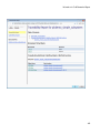
Information in Code Generation Reports . . . . . . . . . . . . . . . .
4-2
Create and Use Code Generation Reports . . . . . . . . . . . . . . .
Generate a Traceability Report from Configuration
Parameters . . . . . . . . . . . . . . . . . . . . . . . . . . . . . . . . . . . .
Keep the Report Current . . . . . . . . . . . . . . . . . . . . . . . . . . .
Trace from Code to Model . . . . . . . . . . . . . . . . . . . . . . . . . . .
Trace from Model to Code . . . . . . . . . . . . . . . . . . . . . . . . . . .
Model Web View in Code Generation Report . . . . . . . . . . . .
Generate a Static Code Metrics Report . . . . . . . . . . . . . . . .
Generate a Traceability Report from the Command Line . . .
4-4
4-4
4-6
4-7
4-8
4-10
4-13
4-14
Working with the Static Code Metrics Report . . . . . . . . . . .
Workflow for Static Code Metrics Report . . . . . . . . . . . . . . .
Report Contents . . . . . . . . . . . . . . . . . . . . . . . . . . . . . . . . .
Function Block Information . . . . . . . . . . . . . . . . . . . . . . . . .
4-16
4-16
4-17
4-18
vii
5
Working with Tunable Parameters in the Simulink
PLC Coder Environment
Tunable Parameters . . . . . . . . . . . . . . . . . . . . . . . . . . . . . . . . .
5-2
Configure Your Model for Tunable Parameters . . . . . . . . . .
5-5
Identify Tunable Parameters . . . . . . . . . . . . . . . . . . . . . . . . . .
5-7
Tune Parameters Using Simulink.Parameter Objects . . . . .
Work Directly with Simulink.Parameter Objects . . . . . . . . .
Work with Simulink.Parameter Objects Using Model
Explorer . . . . . . . . . . . . . . . . . . . . . . . . . . . . . . . . . . . . .
5-11
5-11
Configure Tunable Parameters Using Configuration
Parameters . . . . . . . . . . . . . . . . . . . . . . . . . . . . . . . . . . . . . .
Defining Tunable Parameter Values in the MATLAB
Workspace . . . . . . . . . . . . . . . . . . . . . . . . . . . . . . . . . . . .
Configuring Parameters to Be Tunable . . . . . . . . . . . . . . . .
6
Contents
5-15
5-15
5-17
Controlling Generated Code Partitions
Function Block Partitioning Guidelines . . . . . . . . . . . . . . . . .
6-2
One Function Block for Atomic Subsystems . . . . . . . . . . . . .
6-3
One Function Block for Virtual Subsystems . . . . . . . . . . . . .
6-4
Multiple Function Blocks for Nonvirtual Subsystems . . . . .
6-5
Control Generated Code Using Subsystem Block
Parameters . . . . . . . . . . . . . . . . . . . . . . . . . . . . . . . . . . . . . . .
Generating Separate Partitions and Inlining Subsystem
Code . . . . . . . . . . . . . . . . . . . . . . . . . . . . . . . . . . . . . . . . .
Changing the Name of a Subsystem . . . . . . . . . . . . . . . . . . .
viii
5-13
6-6
6-6
6-7
7
8
9
Integrating Externally Defined Symbols
Integrate Externally Defined Symbols . . . . . . . . . . . . . . . . . .
7-2
Integrate Custom Function Block in Generated Code . . . . .
7-3
IDE-Specific Considerations
Rockwell Automation RSLogix Considerations . . . . . . . . . . .
Add-On Instruction and Function Blocks . . . . . . . . . . . . . . .
Double-Precision Data Types . . . . . . . . . . . . . . . . . . . . . . . . .
Unsigned Integer Data Types . . . . . . . . . . . . . . . . . . . . . . . .
Unsigned Fixed-Point Data Types . . . . . . . . . . . . . . . . . . . . .
Enumerated Data Types . . . . . . . . . . . . . . . . . . . . . . . . . . . .
8-2
8-2
8-2
8-2
8-2
8-3
Siemens SIMATIC STEP 7 Considerations . . . . . . . . . . . . . . .
Double-Precision Floating-Point Data Types . . . . . . . . . . . . .
int8 and Unsigned Integer Types . . . . . . . . . . . . . . . . . . . . .
Unsigned Fixed-Point Data Types . . . . . . . . . . . . . . . . . . . . .
Enumerated Data Types . . . . . . . . . . . . . . . . . . . . . . . . . . . .
8-4
8-4
8-4
8-4
8-5
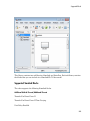
Supported Simulink and Stateflow Blocks
Supported Blocks . . . . . . . . . . . . . . . . . . . . . . . . . . . . . . . . . . . .
View Supported Blocks Library . . . . . . . . . . . . . . . . . . . . . . .
Supported Simulink Blocks . . . . . . . . . . . . . . . . . . . . . . . . . .
Supported Stateflow Blocks . . . . . . . . . . . . . . . . . . . . . . . . .
Blocks With Restricted Support . . . . . . . . . . . . . . . . . . . . .
9-2
9-2
9-3
9-11
9-12
ix
10
Limitations
Coder Limitations . . . . . . . . . . . . . . . . . . . . . . . . . . . . . . . . . .
Current Limitations . . . . . . . . . . . . . . . . . . . . . . . . . . . . . .
Fixed-Point Data Type Limitations . . . . . . . . . . . . . . . . . . .
Multirate Model Limitations . . . . . . . . . . . . . . . . . . . . . . . .
Permanent Limitations . . . . . . . . . . . . . . . . . . . . . . . . . . . .
11
12
Functions — Alphabetical List
Configuration Parameters for Simulink PLC Coder
Models
PLC Coder: General . . . . . . . . . . . . . . . . . . . . . . . . . . . . . . . . .
PLC Coder: General Tab Overview . . . . . . . . . . . . . . . . . . .
Target IDE . . . . . . . . . . . . . . . . . . . . . . . . . . . . . . . . . . . . .
Target IDE Path . . . . . . . . . . . . . . . . . . . . . . . . . . . . . . . . .
Code Output Directory . . . . . . . . . . . . . . . . . . . . . . . . . . . .
Generate testbench for subsystem . . . . . . . . . . . . . . . . . . . .
x
Contents
10-2
10-2
10-2
10-4
10-5
12-2
12-3
12-4
12-6
12-8
12-9
PLC Coder: Comments . . . . . . . . . . . . . . . . . . . . . . . . . . . . .
Comments Overview . . . . . . . . . . . . . . . . . . . . . . . . . . . . .
Include comments . . . . . . . . . . . . . . . . . . . . . . . . . . . . . . .
Include block description . . . . . . . . . . . . . . . . . . . . . . . . . .
Simulink block / Stateflow object comments . . . . . . . . . . .
Show eliminated blocks . . . . . . . . . . . . . . . . . . . . . . . . . . .
12-10
12-11
12-11
12-12
12-13
12-14
PLC Coder: Optimization . . . . . . . . . . . . . . . . . . . . . . . . . . .
Optimization Overview . . . . . . . . . . . . . . . . . . . . . . . . . . .
Signal storage reuse . . . . . . . . . . . . . . . . . . . . . . . . . . . . .
Remove code from floating-point to integer conversions that
wraps out-of-range values . . . . . . . . . . . . . . . . . . . . . . .
Loop unrolling threshold . . . . . . . . . . . . . . . . . . . . . . . . . .
12-15
12-15
12-16
12-18
12-19
PLC Coder: Symbols . . . . . . . . . . . . . . . . . . . . . . . . . . . . . . .
Symbols Overview . . . . . . . . . . . . . . . . . . . . . . . . . . . . . . .
Maximum identifier length . . . . . . . . . . . . . . . . . . . . . . . .
Use the same reserved names as Simulation Target . . . . .
Reserved names . . . . . . . . . . . . . . . . . . . . . . . . . . . . . . . .
Externally Defined Symbols . . . . . . . . . . . . . . . . . . . . . . .
12-20
12-21
12-22
12-23
12-24
12-25
PLC Coder: Report . . . . . . . . . . . . . . . . . . . . . . . . . . . . . . . .
Generate traceability report . . . . . . . . . . . . . . . . . . . . . . .
Generate model Web view . . . . . . . . . . . . . . . . . . . . . . . . .
12-26
12-26
12-27
xi
1
Getting Started
• “Simulink PLC Coder Product Description” on page 1-2
• “PLC Code Generation in the Development Process” on page 1-3
• “Supported IDE Platforms” on page 1-5
• “PLC Code Generation Workflow” on page 1-6
• “Prepare Model for Structured Text Generation” on page 1-7
• “Generate and Examine Structured Text Code” on page 1-15
• “Import Structured Text Code Automatically” on page 1-25
• “Integrate Absolute Time Temporal Logic Code” on page 1-28
• “Simulation and Code Generation of Motion Instructions” on page 1-31
1
Getting Started
Simulink PLC Coder Product Description
Generate IEC 61131-3 Structured Text for PLCs and PACs
Simulink® PLC Coder™ generates hardware-independent IEC 61131-3 Structured Text
from Simulink models, Stateflow® charts, and Embedded MATLAB® functions. The
Structured Text is generated in PLCopen and other file formats supported by widely used
integrated development environments (IDEs). As a result, you can compile and deploy
your application to numerous programmable logic controller (PLC) and programmable
automation controller (PAC) devices.
Simulink PLC Coder generates test benches that help you verify the Structured Text
using PLC and PAC IDEs and simulation tools. Support for industry standards is
available through IEC Certification Kit (for IEC 61508 and IEC 61511).
Key Features
• Automatic generation of IEC 61131-3 Structured Text
• Simulink support, including reusable subsystems, PID controller blocks, and lookup
tables
• Stateflow support, including graphical functions, truth tables, and state machines
• Embedded MATLAB support, including if-else statements, loop constructs, and math
operations
• Support for multiple data types, including Boolean, integer, enumerated, and floatingpoint, as well as vectors, matrices, buses, and tunable parameters
• IDE support, including B&R Automation Studio®, PLCopen, Rockwell Automation®
RSLogix™ 5000, Siemens® SIMATIC® STEP® 7, and Smart Software Solutions
CoDeSys
• Test bench creation
1-2
PLC Code Generation in the Development Process
PLC Code Generation in the Development Process
Simulink PLC Coder software lets you generate IEC 61131-3 compliant Structured Text
code from Simulink models. This software brings the Model-Based Design approach
into the domain of PLC and PAC development. Using the coder, system architects
and designers can spend more time fine-tuning algorithms and models through rapid
prototyping and experimentation, and less time on coding PLCs.
Typically, you use a Simulink model to simulate a design for realization in a PLC.
Once satisfied that the model meets design requirements, run the Simulink PLC Coder
compatibility checker utility. This utility verifies compliance of model semantics and
blocks for PLC target IDE code generation compatibility. Next, invoke the Simulink PLC
Coder tool, using either the command line or the graphical user interface. The coder
generates Structured Text code that implements the design embodied in the model.
Usually, you also generate a corresponding test bench. You can use the test bench
with PLC emulator tools to drive the generated Structured Text code and evaluate its
behavior.
The test bench feature increases confidence in the generated code and saves time spent
on test bench implementation. The design and test process are fully iterative. At any
point, you can return to the original model, modify it, and regenerate code.
At completion of the design and test phase of the project, you can easily export the
generated Structure Text code to your PLC development environment. You can then
deploy the code.
Expected Users
The Simulink PLC Coder product is a tool for control and algorithm design and test
engineers in the following applications:
• PLC manufacturing
• Machine manufacturing
• Systems integration
You should be familiar with:
• MATLAB® and Simulink software and concepts
• PLCs
1-3
1
Getting Started
• Structured Text language
If you want to download generated code to a PLC IDE, you should also be familiar
with your chosen PLC IDE platform. For a list of these platforms, see “Supported IDE
Platforms” on page 1-5.
Glossary
Term
Definition
PAC
Programmable automation controller.
PLC
Programmable logic controller.
IEC 61131-3
IEC standard that defines the Structured Text language for which the
Simulink PLC Coder software generates code.
PLCopen
Vendor- and product-independent organization that works with the
IEC 61131-3 standard. The Simulink PLC Coder product can generate
Structured Text using the PLCopen XML standard format. See http://
www.plcopen.org/pages/tc6_xml/xml_intro/index.htm for details.
Structured Text
High-level textual language defined by IEC 61131-3 standard for the
programming of PLCs.
function block
Structured Text language programming concept that allows the
encapsulation and reuse of algorithmic functionality.
System Requirements
For a list of related products, see System Requirements at the MathWorks® website.
1-4
Supported IDE Platforms
Supported IDE Platforms
The Simulink PLC Coder product is tested with the following IDE platforms:
• 3S-Smart Software Solutions CoDeSys Version 2.3 or 3.3 or 3.5
• B&R Automation Studio 3.0 or 4
• Beckhoff® TwinCAT® 2.11 or 3
• KW-Software MULTIPROG® 5.0
The Simulink PLC Coder software supports only the English version of KW-Software
MULTIPROG target IDE.
• OMRON® Sysmac® Studio Version 1.04, 1.05, or 1.09
• Phoenix Contact® PC WORX™ 6.0
The Simulink PLC Coder software supports only the English version of Phoenix
Contact PC WORX target IDE.
• Rexroth IndraWorks version 13V12 IDE
• Rockwell Automation RSLogix 5000 Series Version 17, 18, or 19
The Simulink PLC Coder software can generate code for Add-On instructions (AOIs)
and routine code.
• Siemens SIMATIC STEP 7 Version 5.4 or 5.5
The Simulink PLC Coder software assumes that English systems use English S7. It
assumes that German systems use German S7.
• Generic
• PLCopen XML
For a list of supported IDEs and platforms, see Supported IDEs at the MathWorks
website.
1-5
1
Getting Started
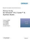
PLC Code Generation Workflow
Your basic Simulink PLC Coder workflow is:
1
Define and design a Simulink model from which you want to generate code.
2
Identify the model components for which you want to generate code for importing to
a PLC.
3
Place the components in a Subsystem block.
4
Identify your target PLC IDE.
5
Select a solver.
6
Configure the Subsystem block to be atomic.
7
Check that the model is compatible with the Simulink PLC Coder software.
8
Simulate your model.
9
Configure model parameters to generate code for your PLC IDE.
10 Examine the generated code.
11 Import code to your PLC IDE.
1-6
Prepare Model for Structured Text Generation
Prepare Model for Structured Text Generation
In this section...
“Tasking Mode” on page 1-7
“Solvers” on page 1-7
“Configuring Simulink Models for Structured Text Code Generation” on page 1-7
“Checking System Compatibility for Structured Text Code Generation” on page 1-12
Tasking Mode
This step is only required if your Simulink model contains multi-rate signals. If your
Simulink model does not contain multi-rate signals, you may proceed to solver selection.
Simulink PLC Coder only generates code for single-tasking subsystems. For multirate subsystems, you must first explicitly set the tasking mode to single-tasking before
selecting a solver. On the Solver Options pane, select fixed step. Select SingleTasking
for tasking mode for periodic sample times.
Solvers
Choose a solver for your Simulink PLC Coder model.
Model
Solver Setting
Variable-step
Use a continuous solver. Configure a fixed sample time for the
subsystem for which you generate code.
Fixed-step
Use a discrete fixed-step solver.
Configuring Simulink Models for Structured Text Code Generation
You must already have a model for which you want to generate and import code to a PLC
IDE. Before you use this model, perform the following steps.
1
In the Command Window, open your model.
1-7
1
Getting Started
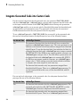
2
Configure the model to use the fixed-step discrete solver. Select Simulation >
Model Configuration Parameters and in the Solver pane, set Type to Fixedstep and Solver to discrete (no continuous states).
If your model uses a continuous solver, has a subsystem, configure a fixed sample
time for the subsystem for which you generate code.
1-8
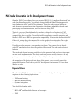
3
Save this model as plcdemo_simple_subsystem1.
4
Create a subsystem containing the components for which you want to generate
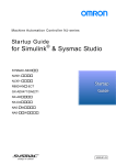
Structured Text code.
Prepare Model for Structured Text Generation
Optionally, rename In1 and Out1 to U and Y respectively. This operation results in a
subsystem like the following figure:
5
Save the model with the new subsystem.
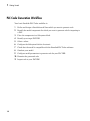
6
In the top-level model, right-click the Subsystem block and select Block
Parameters (Subsystem).
1-9
1
Getting Started
7
1-10
In the resulting block dialog box, select Treat as atomic unit.
Prepare Model for Structured Text Generation
8
Click OK.
9
Simulate your model.
10 Save your model. In later procedures, you can use either this model, or the
plcdemo_simple_subsystem model that comes with your software.
You are now ready to:
1-11
1
Getting Started
• Set up your subsystem to generate Structured Text code. See “Checking System
Compatibility for Structured Text Code Generation” on page 1-12.
• Generate Structured Text code for your IDE. See “Generate and Examine Structured
Text Code” on page 1-15.
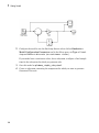
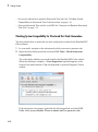
Checking System Compatibility for Structured Text Code Generation
You must already have a model that you have configured to work with the Simulink PLC
Coder software.
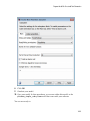
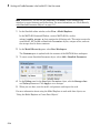
1
In your model, navigate to the subsystem for which you want to generate code.
2
Right-click that Subsystem block and select PLC Code > Check Subsystem
Compatibility.
The coder checks whether your model satisfies the Simulink PLC Coder criteria.
When the checking is complete, a View diagnostics hyperlink appears at the
bottom of the model window. Click this hyperlink to open the Diagnostic Viewer
window.
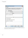
If the subsystem is not atomic, right-click the Subsystem block and select PLC
Code, which prompts Enable “Treat as atomic unit” to generate code.
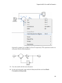
1-12
Prepare Model for Structured Text Generation
This command opens the block parameter dialog box. Select Treat as atomic unit.
1-13
1
Getting Started
You are now ready to generate Structured Text code for your IDE. See “Generate and
Examine Structured Text Code” on page 1-15.
1-14
Generate and Examine Structured Text Code
Generate and Examine Structured Text Code
In this section...
“Generate Structured Text from the Model Window” on page 1-15
“Generate Structured Text with the MATLAB Interface” on page 1-20
“Generate Structured Text Code and Integrate with Existing Siemens SIMATIC STEP 7
Projects” on page 1-21
“Matrix Data Types” on page 1-22
“Generated Code Header” on page 1-22
“Specify Custom Names for Generated Files” on page 1-22
“Propagation of Block Descriptions” on page 1-23
“Internal Signals for Debugging in RSLogix 5000 IDE” on page 1-23
Generate Structured Text from the Model Window
You must already have set up your environment and Simulink model to use the Simulink
PLC Coder software to generate Structured Text code. If you have not yet done so, see
“Prepare Model for Structured Text Generation” on page 1-7.
1
If you do not have the plcdemo_simple_subsystem model open, open it now.
2
Right-click the Subsystem block and select PLC Code > Options.
The Configuration Parameters dialog box is displayed.
1-15
1
Getting Started
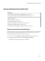
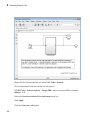
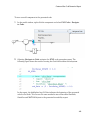
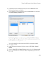
3
In PLC Code Generation > General options > Target IDE, select a target IDE.
For example, select CoDeSys 2.3.
4
Click Apply.
5
Click Generate code.
This button:
• Generates Structured Text code (same as the PLC Code > Generate Code for
Subsystem option)
• Stores generated code in model_name.exp (for example,
plcdemo_simple_subsystem.exp)
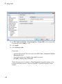
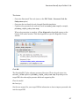
When code generation is complete, a View diagnostics hyperlink appears at the
bottom of the model window. Click this hyperlink to open the Diagnostic Viewer
window.
1-16
Generate and Examine Structured Text Code
This window has links that you can click to open the associated files.
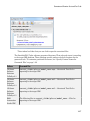
The Simulink PLC Coder software generates Structured Text code and stores it according
to the target IDE platform. These platform-specific paths are default locations for the
generated code. To customize generated file names, see “Specify Custom Names for
Generated Files” on page 1-22.
Platform
Generated Files
3S-Smart
Software
Solutions
CoDeSys 2.3
current_folder\plcsrc\model_name.exp — Structured Text file for
importing to the target IDE.
3S-Smart
Software
Solutions
CoDeSys 3.3
current_folder\plcsrc\model_name.xml — Structured Text file for
importing to the target IDE.
3S-Smart
Software
Solutions
CoDeSys 3.5
current_folder\plcsrc\model_name.xml — Structured Text file for
importing to the target IDE.
B&R
Automation
Studio IDE
The following files in current_folder\plcsrc\model_name — Files for
importing to the target IDE:
1-17
1
Getting Started
Platform
Generated Files
• Package.pkg — (If test bench is generated) Top-level package file for
function blocks library and test bench main program in XML format.
In the main folder (if test bench is generated):
• IEC.prg — Test bench main program definition file in XML format.
• mainInit.st — Text file. Test bench init program file in Structured Text.
• mainCyclic.st — Text file. Test bench cyclic program file in Structured
Text.
• mainExit.st — Text file. Test bench exit program file in Structured Text.
• main.typ — Text file. Main program type definitions file in Structured Text.
• main.var — Text file. Main program variable definitions file in Structured
Text.
Beckhoff
TwinCAT 2.11
current_folder\plcsrc\model_name.exp — Structured Text file for
importing to the target IDE.
KW-Software
MULTIPROG
5.0
current_folder\plcsrc\model_name.xml — Structured Text file, in XML
format, for importing to the target IDE.
Phoenix
Contact PC
WORX 6.0
current_folder\plcsrc\model_name.xml — Structured Text file, in XML
format, for importing to the target IDE.
Rockwell
Automation
RSLogix 5000
IDE: AOI
current_folder\plcsrc\model_name.L5X — (If test bench is generated)
Structured Text file for importing to the target IDE using Add-On Instruction
(AOI) constructs. This file is in XML format and contains the generated
Structured Text code for your model.
1-18
Generate and Examine Structured Text Code
Platform
Generated Files
Rockwell
Automation
RSLogix 5000
IDE: Routine
current_folder\plcsrc\model_name.L5X — (If test bench is generated)
Structured Text file for importing to the target IDE using routine constructs. This
file is in XML format and contains the generated Structured Text code for your
model.
In current_folder\plcsrc\model_name (if test bench is not generated), the
following files are generated:
• subsystem_block_name.L5X — Structured Text file in XML format.
Contains program tag and UDT type definitions and the routine code for the
top-level subsystem block.
• routine_name.L5X — Structured Text files in XML format. Contains routine
code for other subsystem blocks.
Siemens
SIMATIC
STEP 7 IDE
current_folder\plcsrc\model_name\model_name.scl — Structured Text
file for importing to the target IDE.
Generic
current_folder\plcsrc\model_name.st — Pure Structured Text file. If
your target IDE is not available for the Simulink PLC Coder product, consider
generating and importing a generic Structured Text file.
PLCopen XML
current_folder\plcsrc\model_name.xml — Structured Text file formatted
using the PLCopen XML standard. If your target IDE is not available for the
Simulink PLC Coder product, but uses a format like this standard, consider
generating and importing a PLCopen XML Structured Text file.
current_folder\plcsrc\model_name\model_name.asc — (If test bench
is generated) Text file. Structured Text file and symbol table for generated test
bench code.
The example in this topic illustrates generated code for the CoDeSys Version 2.3 PLC
IDE. Generated code for other platforms, such as Rockwell Automation RSLogix 5000, is
in XML or other format and looks different.
1-19
1
Getting Started
For a description of how the generated code for the Simulink components map to
Structured Text components, see “Simulink PLC Coder Mapping Semantics”.
If you are confident that the generated Structured Text is good, optionally change
your workflow to automatically generate and import code to the target IDE. For more
information, see “Import Structured Text Code Automatically” on page 1-25.
Generate Structured Text with the MATLAB Interface
You can generate Structured Text code for a subsystem in the Command Window with
the plcgeneratecode function. You must have already configured the parameters for
the model or, alternatively, you may use the default settings.
For example, to generate code from the SimpleSubsystem subsystem in the
plcdemo_simple_subsystem model:
1-20
Generate and Examine Structured Text Code
1
Open the plcdemo_simple_subsystem model:
plcdemo_simple_subsystem
2
Open the Configuration Parameters dialog box using the plcopenconfigset
function:
plcopenconfigset('plcdemo_simple_subsystem/SimpleSubsystem')
3
Select a target IDE.
4
Configure the subsystem as described in “Prepare Model for Structured Text
Generation” on page 1-7.
5
Generate code for the subsystem:
generatedfiles = plcgeneratecode('plcdemo_simple_subsystem/SimpleSubsystem')
Generate Structured Text Code and Integrate with Existing Siemens
SIMATIC STEP 7 Projects
Following is a workflow to integrate generated code into an existing Siemens SIMATIC
STEP 7 project.
• You must have already generated code for the Siemens SIMATIC STEP 7 target IDE.
If you have not yet done so, see “Generate Structured Text from the Model Window”
on page 1-15.
• You must have a Siemens SIMATIC STEP 7 project into which you want to integrate
the generated code.
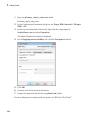
1
In the Siemens SIMATIC STEP 7 project, right-click Sources and select Insert
New Object > External Source.
2
In the browser window, navigate to the folder that contains the Simulink PLC Coder
generated code you want to integrate.
3
In this folder, select model_name.scl, then click OK.
A new entry named model_name appears in the Sources folder.
4
In the Sources folder, double-click model_name.
The generated code is listed in the SCL editor window.
5
In the SCL editor window, select Options > Customize.
6
In the customize window, select Create block numbers automatically.
1-21
1
Getting Started
7
Click OK.
This action enables the software to generate automatically the symbol addresses for
Subsystem blocks.
8
In the SCL editor window, compile the model_name.scl file for the Subsystem
block.
The new Function Block is now integrated and available for use with the existing
Siemens SIMATIC STEP 7 project.
Matrix Data Types
The coder converts matrix data types to single-dimensional vectors (column-major) in the
generated Structured Text.
Generated Code Header
After generating Structured Text code, examine it. If your model has author names,
creation dates, and model descriptions, the generated code contains these items in the
header comments. The header also lists fundamental sample times for the model and the
subsystem block for which you generate code.
Specify Custom Names for Generated Files
To specify a different name for the generated files, set the Function name options
parameter in the Subsystem block:
1
Right-click the Subsystem block for which you want to generate code and select
Subsystem Parameters.
2
In the Main tab, select the Treat as atomic unit check box.
3
Click the Code Generation tab.
4
From the Function Packaging parameter list, select either Nonreusable
function or Reusable Function.
These options enable the Function name options and File name options
parameters.
5
1-22
Select the option that you want to use for generating the file name.
Generate and Examine Structured Text Code
Function name options
Generated File Name
Auto
Default. Uses the model name, as listed
in “Prepare Model for Structured Text
Generation” on page 1-7, for example,
plcdemo_simple_subsystem.
Use subsystem name
Uses the subsystem name, for example,
SimpleSubsystem.
User specified
Uses the custom name that you specify
in the Function name parameter, for
example, SimpleSubsystem.
Propagation of Block Descriptions
To propagate blocks to generated code:
1
Right-click the block for which you want to propagate comments.
2
From the menu, select Properties.
3
In the General tab, navigate to the Description section and enter the text that you
want to propagate and save the changes.
4
In the Configuration Parameters dialog box, click the PLC Code Generation >
Comments > Include block description check box and save the changes.
5
Generate code for the model as usual and observe that the comments have
propagated to the generated code.
For Rockwell Automation RSLogix 5000 AOI/routine target IDEs, the coder also
generates the subsystem block description text as an AOI or routine description L5X
XML tag. The IDE can then import the tag as part of AOI and routine definition in the
generated code.
Internal Signals for Debugging in RSLogix 5000 IDE
For debugging, you can generate code for test point outputs from the top level subsystem
of your model. The coder generates code that maps the test pointed output to optional
AOI output parameters for RSLogix 5000 IDEs. In the generated code, the variable
tags that correspond to the test points have the property Required=false. This
example assumes that you have a model appropriately configured for the coder, such as
plcdemo_simple_subsystem.
1-23
1
Getting Started
1
Open the plcdemo_simple_subsystem model.
plcdemo_simple_subsystem
2
In the Configuration Parameters dialog box, set Target IDE to Rockwell RSLogix
5000: AOI.
3
In the top level subsystem of the model, right-click the output signal of
SimpleSubsystem and select Properties.
The Signal Properties dialog box is displayed.
4
On the Logging and accessibility tab, click the Test point check box.
5
Click OK.
6
Generate code for the top level subsystem.
7
Inspect the generated code for the string Required=false.
For more information on signals with test points, see “What Is a Test Point?”.
1-24
Import Structured Text Code Automatically
Import Structured Text Code Automatically
In this section...
“PLC IDEs That Qualify for Importing Code Automatically” on page 1-25
“Generate and Automatically Import Structured Text Code” on page 1-25
“Troubleshoot Automatic Import Issues” on page 1-26
PLC IDEs That Qualify for Importing Code Automatically
If you are confident that your model produces Structured Text that does not require
visual examination, you can generate and automatically import Structured Text code to
one of the following target PLC IDEs:
• 3S-Smart Software Solutions CoDeSys Version 2.3
• KW-Software MULTIPROG Version 5.0
• Phoenix Contact PC WORX Version 6.0
• Rockwell Automation RSLogix 5000 Version 17, 18, or 19
For the Rockwell Automation RSLogix routine format, you must generate testbench
code for automatic import and verification.
• Siemens SIMATIC STEP 7 Version 5.4 only for the following versions:
• Siemens SIMATIC Manager: Version V5.4+SP5+HF1, Revision K5.4.5.1
• S7-SCL: Version V5.3+SP5, Revision K5.3.5.0
• S7-PLCSIM: Version V5.4+SP3, Revision K5.4.3.0
Working with the default CoDeSys Version 2.3 IDE should require additional changes
for only the KW-Software MULTIPROG 5.0 and Phoenix Contact PC WORX 6.0 IDE.
For information about automatically importing Structured Text code to these IDEs,
see “Import and Verify Structured Text to KW-Software MULTIPROG 5.0 and Phoenix
Contact PC WORX 6.0 IDEs Automatically” on page 3-8.
Generate and Automatically Import Structured Text Code
You can generate and automatically import Structured Text code. Before you start:
• In the target IDE, save your current project.
1-25
1
Getting Started
• Close open projects.
• Close the target IDE and target IDE-related windows.
Note: While the automatic import process is in progress, do not touch your mouse or
keyboard. Doing so might disrupt the process. When the process completes, you can
resume normal operations.
You must have already installed your target PLC IDE in a default location, and it must
use the CoDeSys V2.3 IDE. If you installed the target PLC IDE in a nondefault location,
open the Configuration Parameters dialog box. In the PLC Coder node, set the Target
IDE Path parameter to the installation folder of your PLC IDE. See “Target IDE Path”.
1
If it is not already started, open the Command Window.
2
Open the plcdemo_simple_subsystem model.
3
Right-click the Subsystem block and select PLC Code > Generate and Import
Code for Subsystem.
The software:
a
Generates the code.
b
Starts the target IDE interface.
c
Creates a new project.
d
Imports the generated code to the target IDE.
If you want to generate, import, and run the Structured Text code, see “Import and
Verify Structured Text Code Automatically” on page 3-8.
Troubleshoot Automatic Import Issues
Following are guidelines, hints, and tips for questions or issues you might have while
using the automatic import capability of the Simulink PLC Coder product.
Supported Target IDEs
The Simulink PLC Coder software supports only the following versions of target IDEs for
automatic import and verification:
• 3S-Smart Software Solutions CoDeSys Version 2.3
1-26
Import Structured Text Code Automatically
• KW-Software MULTIPROG 5.0 (English)
• Phoenix Contact PC WORX 6.0 (English)
• Rockwell Automation RSLogix 5000 Series Version 17, 18, 19 (English)
For the Rockwell Automation RSLogix routine format, you must generate testbench
code for automatic import and verification.
• Siemens SIMATIC STEP 7 Version 5.4 (English and German)
Unsupported Target IDEs
The following target IDEs currently do not support automatic import. For these target
IDEs, the automatic import menu items (Generate and Import Code for Subsystem
and Generate, Import, and Verify Code for Subsystem) are disabled.
• 3S-Smart Software Solutions CoDeSys Version 3.3
• 3S-Smart Software Solutions CoDeSys Version 3.5
• B&R Automation Studio IDE
• Beckhoff TwinCAT 2.11
• Generic
• PLCopen
Possible Automatic Import Issues
When the Simulink PLC Coder software fails to finish automatically importing for the
target IDE, it reports an issue in a message dialog box. To remedy the issue, try the
following actions:
• Check that the coder supports the target IDE version and language setting
combination.
• Check that you have specified the target IDE path in the subsystem Configuration
Parameters dialog box.
• Close currently open projects in the target IDE, close the target IDE completely, and
try again.
• Some target IDEs can have issues supporting the large data sets the coder test bench
generates. In these cases, try to shorten the simulation cycles to reduce the data set
size, then try the automatic import again.
• Other applications can interfere with automatic importing to a target IDE. Try to
close other unrelated applications on the system and try the automatic import again.
1-27
1
Getting Started
Integrate Absolute Time Temporal Logic Code
In this section...
“Absolute Time Temporal Logic Considerations” on page 1-28
“Absolute Time Temporal Logic Workflow” on page 1-28
“Create PLC_CODER_TIMER Function Block” on page 1-28
“Generate Code with Absolute Time Temporal Logic” on page 1-30
Absolute Time Temporal Logic Considerations
Simulink PLC Coder supports absolute time temporal logic for the Rockwell Automation
RSLogix 5000 IDE. For other targets, use the following workflow to generate code with
absolute time temporal logic.
This workflow refers to plcdemo_sf_abs_time as an example of a model that contains
absolute time temporal logic constructs.
Before you start, make sure that you have a Stateflow license. The coder supports
absolute time temporal logic constructs that you specify in Stateflow charts.
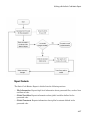
Absolute Time Temporal Logic Workflow
1
Create the PLC_CODER_TIMER timer function block in your target integrated
development environment (IDE).
When the Simulink PLC Coder product generates code for a model that uses absolute
time temporal logic, it generates calls to this block.
2
Insert the IDE-specific code into the timer function block.
3
Create your Simulink model using Stateflow charts for temporal logic constructs.
4
Generate PLC code from your model and integrate it with the PLC_CODER_TIMER
function block in your IDE.
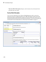
Create PLC_CODER_TIMER Function Block
1
1-28
In your IDE, create the PLC_CODER_TIMER function block for your absolute time
temporal logic constructs. For an example template of a PLC_CODER_TIMER
Integrate Absolute Time Temporal Logic Code
definition for the generic IDE, see \toolbox\plccoder\plccoderdemos
\plc_coder_timer.st. The input/output interface and logic must match the
definition in the example.
2
The PLC_CODER_TIMER function block is a template. Define the code for the timer
logic. Modify the function block by inserting the IDE-specific code for RESET,
BEFORE, and AFTER timer instructions.
1-29
1
Getting Started
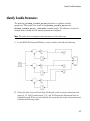
Generate Code with Absolute Time Temporal Logic
1-30
1
Create your Simulink model using absolute time temporal logic constructs.
Include the temporal logic constructs in a Stateflow chart. For an example, see
plcdemo_sf_abs_time.
2
Configure the chart to generate Simulink PLC Coder code.
3
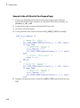
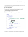
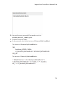
Generate code for the model.
4
In the generated code, look for instances of PLC_CODER_TIMER. For example:
5
Integrate the generated code and the PLC_CODER_TIMER function block into your
IDE.
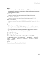
Simulation and Code Generation of Motion Instructions
Simulation and Code Generation of Motion Instructions
In this section...
“Workflow for Using Motion Instructions in Model” on page 1-31
“Library of Motion Instructions” on page 1-33
“Data Types for Motion Instructions” on page 1-34
“Limitations for MAM Instruction” on page 1-34
The Simulink PLC Coder software supports a workflow for the behavioral simulation and
code generation of motion instructions for the Rockwell Automation RSLogix 5000 IDE.
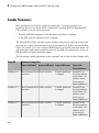
Workflow for Using Motion Instructions in Model
This workflow uses plcdemo_motion_control in the plcdemos folder. This example
provides a template that you can use with motion instructions. It contains the following
subsystems.
Subsystem
Description
Controller
Contains an example Stateflow chart with motion
instructions. The controller subsystem sends input
to the Command Profile subsystem (part of the
template).
Replace this subsystem with your own controller
subsystem.
Command Profile
Contains a utility subsystem in which the coder
calculates the position data based on the parameters
of the motion instructions MAM command.
Drive Model
Contains a minimalistic drive model.
Replace this subsystem with your own drive model
subsystem.
Drive Status
Contains a utility subsystem that reads drive status
and returns that status to the Controller subsystem.
Typically, you do not need to modify or replace this
subsystem.
1-31
1
Getting Started
Before you start, create:
• A custom controller subsystem. This subsystem contains motion instructions. The
controller subsystem sends input to the Command Profile subsystem.
• A custom drive (plant) model subsystem. The subsystem sends input to a Drive Status
subsystem. Design the subsystem to work with the inputs and outputs.
To modify the plcdemo_motion_control example:
1
Open the plcdemo_motion_control example template.
2
In the Controller subsystem, replace the ExampleController chart with your
controller subsystem.
3
In the template, replace the Drive Model subsystem with your drive (plant) model.
4
Simulate the model.
5
Observe the simulation results in the model scopes.
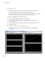
The following plots show the output from plcdemo_motion_control without
modification.
1-32
Simulation and Code Generation of Motion Instructions
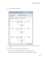
6
Generate code for the example model. To view the code in HTML format, in the coder
configuration parameters, select the PLC Code Generation > Report > Generate
traceability report check box and click Apply.
Navigate to the PLC Code Generation node and click Generate code.
An HTML file of the generated code is displayed.
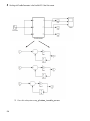
7
Observe the generated code for MAM, MAFR, and MSO.
MAFR and MSO
MAM
Library of Motion Instructions
The plcdemo_motion_control example uses a motion instructions library that
contains a Motion Stub Functions Stateflow chart. This chart defines stub functions for
only the following motion instructions:
• MAM
• MAFR
• MSO
1-33
1
Getting Started
To use other Rockwell Automation RSLogix motion instructions in the model, you must
define your own stub functions to correspond to the RSLogix motion instructions in the
Motion Stub Functions chart.
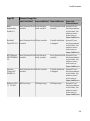
Data Types for Motion Instructions
The plcdemo_motion_control example uses Simulink bus data types
(Simulink.Bus). These data types correspond to the motion instruction AXIS and
MOTION_INSTRUCTION user-defined data types (UDTs) in the Rockwell Automation
RSLogix 5000 IDE. For these UDTs, the example defines only the fields used in the
ExampleController chart of the plcdemo_motion_control example. When you
generate code, the coder maps the bus data types to the motion instruction UDTs. If your
controller subsystem uses other fields of motion instruction UDTs, you must add them to
the definition of the corresponding Simulink bus data types. The /toolbox/plccoder/
plccoderdemos/PLCMotionType.mat file contains the definitions of the Simulink bus
data types. You can add more fields to these definitions as required by your controller.
Name
AXIS_SERVO_DRIVE
MOTION_INSTRUCTION
Size
1x1
1x1
Bytes Class
Simulink.Bus
Simulink.Bus
Attributes
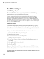
Limitations for MAM Instruction
In the plcdemo_motion_control example, the MAM instruction has the following
limitations:
• Direction parameter is always forward.
• The software supports only the Trapezoidal profile.
• The software ignores units parameters.
• The software does not support Merge and Merge speed.
1-34
2
Mapping Simulink Semantics to
Structured Text
• “Simulink PLC Coder Mapping Semantics” on page 2-2
• “Generated Code Structure for Simple Simulink Subsystems” on page 2-3
• “Generated Code Structure for Reusable Subsystems” on page 2-5
• “Generated Code Structure for Triggered Subsystems” on page 2-7
• “Generated Code Structure for Stateflow Charts” on page 2-9
• “Generated Code Structure for MATLAB Function Block” on page 2-11
• “Generated Code Structure for Multirate Models” on page 2-13
• “Generated Code Structure for Subsystem Mask Parameters” on page 2-15
• “Global Tunable Parameter Initialization for PC WORX” on page 2-20
2
Mapping Simulink Semantics to Structured Text
Simulink PLC Coder Mapping Semantics
When you examine generated code, you evaluate how well the Simulink PLC Coder
software has generated code from your model. The following topics describe how the
coder maps Simulink subsystem semantics to function block semantics in Structured
Text. As examples, the topics describe the mapping in the context of the different
subsystem types that Simulink supports. The examples assume that you have already
generated code (see “Generate Structured Text from the Model Window”). These
topics use code generated with CoDeSys Version 2.3. Examples are located in the
matlabroot\toolbox\plccoder\plccoderdemos folder.
2-2
Generated Code Structure for Simple Simulink Subsystems
Generated Code Structure for Simple Simulink Subsystems
This topic assumes that you have generated Structured Text code from a Simulink
model. If you have not yet done so, see “Generate Structured Text from the Model
Window”.
The example in this topic shows generated code for the CoDeSys Version 2.3 IDE.
Generated code for other IDE platforms looks different.
1
If you do not have the plcdemo_simple_subsystem.exp file open, open it in the
MATLAB editor. In the folder that contains the file, type:
edit plcdemo_simple_subsystem.exp
A file like the following is displayed.
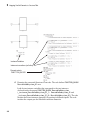
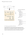
The following figure illustrates the mapping of the generated code to Structured Text
components for a simple Simulink subsystem. The Simulink subsystem corresponds
to the Structured Text function block, Subsystem.
Note: The coder maps alias data types to the base data type in the generated code.
2-3
2
Mapping Simulink Semantics to Structured Text
Input parameter for
subsystem method
type
Atomic subsystem name
Subsystem
Subsystem
inputs and
outputs
Subsystem
State (DWork)
variables
Initialize and
step methods
Inlined
parameters
2
2-4
Inspect this code as you ordinarily do for PLC code. Check the generated code.
Generated Code Structure for Reusable Subsystems
Generated Code Structure for Reusable Subsystems
This topic assumes that you have generated Structured Text code from a Simulink
model. If you have not yet done so, see “Generate Structured Text from the Model
Window”.
The example in this topic shows generated code for the CoDeSys Version 2.3 IDE.
Generated code for other IDE platforms looks different.
1
Open the plcdemo_reusable_subsystem model.
2
Right-click the Subsystem block and select PLC Code > Generate Code for
Subsystem.
The Simulink PLC Coder software generates Structured Text code and places it in
current_folder/plcsrc/plcdemo_reusable_subsystem.exp.
3
If you do not have the plcdemo_reusable_subsystem.exp file open, open it in the
MATLAB editor.
The following figure illustrates the mapping of the generated code to Structured
Text components for a reusable Simulink subsystem . This graphic contains a copy
of the hierarchical subsystem, ReusableSubsystem. This subsystem contains two
identical subsystems, S1 and S2. This configuration enables code reuse between the
two instances (look for the ReusableSubsystem string in the code).
2-5
2
Mapping Simulink Semantics to Structured Text
Instance variables
Instance invocations (call sites)
Reused code in
FUNCTION_BLOCK
4
Examine the generated Structured Text code. The code defines FUNCTION_BLOCK
ReusableSubsystem_S1 once.
Look for two instance variables that correspond to the two instances
declared inside the parent FUNCTION_BLOCK ReusableSubsystem
(_instance_ReusableSubsystem_S1_1: ReusableSubsystem_S1 and
_instance_ReusableSubsystem_S1_0: ReusableSubsystem_S1). The code
invokes these two instances separately by passing in different inputs. The code
invokes the outputs per the Simulink execution semantics.
2-6
Generated Code Structure for Triggered Subsystems
Generated Code Structure for Triggered Subsystems
This topic assumes that you have generated Structured Text code from a Simulink
model. If you have not yet done so, see “Generate Structured Text from the Model
Window”.
The example in this topic shows generated code for the CoDeSys Version 2.3 PLC IDE.
Generated code for other IDE platforms looks different.
1
Open the plcdemo_cruise_control model.
2
Right-click the Controller subsystem block and select PLC Code > Generate Code
for Subsystem.
The Simulink PLC Coder software generates Structured Text code and places it in
current_folder/plcsrc/plcdemo_cruise_control.exp.
3
If you do not have the plcdemo_cruise_control.exp file open, open it in the
MATLAB editor.
The following figure illustrates the mapping of the generated code to Structured
Text components for a triggered Simulink subsystem . The first part of the figure
shows the Controller subsystem and the triggered Stateflow chart that it contains.
The second part of the figure shows excerpts of the generated code. Notice the zerocrossing functions that implement the triggered subsystem semantics.
Subsystem
Triggered Stateflow Chart
2-7
2
Mapping Simulink Semantics to Structured Text
Generated code
Triggered subsystem semantics
2-8
Generated Code Structure for Stateflow Charts
Generated Code Structure for Stateflow Charts
This topic assumes that you have generated Structured Text code from a Simulink
model. If you have not yet done so, see “Generate Structured Text from the Model
Window”.
The example in this topic shows generated code for the CoDeSys Version 2.3 PLC IDE.
Generated code for other IDE platforms looks different.
1
Open the plcdemo_stateflow_controller model.
2
Right-click the ControlModule chart and select PLC Code > Generate Code for
Subsystem.
The Simulink PLC Coder software generates Structured Text code and places it in
current_folder/plcsrc/plcdemo_stateflow_controller.exp.
3
If you do not have the plcdemo_stateflow_controller.exp file open, open it in
the MATLAB editor.
The following figure illustrates the mapping of the generated code to Structured Text
components for a Simulink Subsystem block that contains a Stateflow chart.
2-9
2
Mapping Simulink Semantics to Structured Text
Inlined code for Stateflow chart
4
Examine the generated Structured Text code.
The Simulink PLC Coder software aggressively inlines the generated code for the
Stateflow chart. The coder performs this inlining because different functions from
Stateflow charts share some global state data. However, function blocks in Structured
Text code do not share state data. As a result, the coder software cannot map these
functions onto separate function blocks. Instead, it must inline these functions.
2-10
Generated Code Structure for MATLAB Function Block
Generated Code Structure for MATLAB Function Block
This topic assumes that you have generated Structured Text code from a Simulink
model. If you have not yet done so, see “Generate Structured Text from the Model
Window”.
The example in this topic shows generated code for the CoDeSys Version 2.3 IDE.
Generated code for other IDE platforms looks different.
1
Open the plcdemo_eml_tankcontrol model.
2
Right-click the TankControl block and select PLC Code > Generate Code for
Subsystem.
The Simulink PLC Coder software generates Structured Text code and places it in
current_folder/plcsrc/plcdemo_eml_tankcontrol.exp.
3
If you do not have the plcdemo_eml_tankcontrol.exp file open, open it in the
MATLAB editor.
The following figure illustrates the mapping of the generated code to Structured
Text components for a Simulink Subsystem block that contains a MATLAB Function
block. The coder tries to perform inline optimization on the generated code for
MATLAB local functions. If the coder determines that it is more efficient to leave the
local function as is, it places the generated code in a Structured Text construct called
FUNCTION.
4
Examine the generated Structured Text code.
2-11
2
Mapping Simulink Semantics to Structured Text
MATLAB code
Generated code
for MATLAB
subfunctions
2-12
Generated Code Structure for Multirate Models
Generated Code Structure for Multirate Models
This example assumes that you have generated Structured Text code from a Simulink
model. If you have not yet done so, see “Generate Structured Text from the Model
Window”.
The example in this topic shows generated code for the CoDeSys Version 2.3 IDE.
Generated code for other IDE platforms looks different.
1
Open the plcdemo_multirate model. This model has two sample rates.
2
Right-click the SimpleSubsystem block and select PLC Code > Generate Code
for Subsystem.
The Simulink PLC Coder software generates Structured Text code and places it in
current_folder/plcsrc/plcdemo_multirate.exp.
3
If you do not have the plcdemo_multirate.exp file open, open it in the MATLAB
editor and examine the Structured Text code.
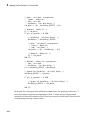
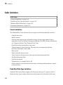
The generated code contains a global time step counter variable:
VAR_GLOBAL
plc_ts_counter1: DINT;
END_VAR
In this example, there are two rates, and the fast rate is twice as fast as the slow
rate, so the time step counter counts to 1, then resets:
IF plc_ts_counter1 >= 1 THEN
plc_ts_counter1 := 0;
ELSE
plc_ts_counter1 := plc_ts_counter1 + 1;
END_IF;
The generated code for blocks running at slower rates executes conditionally based
on the corresponding time step counter values. In this example, the generated
code for Gain1, Unit Delay1, and Sum1 executes every other time step, when
plc_ts_counter1 = 0, because those blocks run at the slow rate. The generated
code for Gain, Unit Delay, Sum, and Sum2 executes every time step because those
blocks run at the fast rate.
SS_STEP:
2-13
2
Mapping Simulink Semantics to Structured Text
(* Gain: '<S1>/Gain' incorporates:
* Inport: '<Root>/U1'
* Sum: '<S1>/Sum'
* UnitDelay: '<S1>/Unit Delay' *)
rtb_Gain := (U1 - UnitDelay_DSTATE) * 0.5;
(* Outport: '<Root>/Y1' *)
Y1 := rtb_Gain;
IF plc_ts_counter1 = 0 THEN
(* UnitDelay: '<S1>/Unit Delay1' *)
UnitDelay1 := UnitDelay1_DSTATE;
(* Gain: '<S1>/Gain1' incorporates:
* Inport: '<Root>/U2'
* Sum: '<S1>/Sum1' *)
rtb_Gain1 := (U2 - UnitDelay1) * 0.5;
(* Outport: '<Root>/Y2' *)
Y2 := rtb_Gain1;
END_IF;
(* Outport: '<Root>/Y3' incorporates:
* Sum: '<S1>/Sum2'
* UnitDelay: '<S1>/Unit Delay' *)
Y3 := UnitDelay_DSTATE - UnitDelay1;
(* Update for UnitDelay: '<S1>/Unit Delay' *)
UnitDelay_DSTATE := rtb_Gain;
IF plc_ts_counter1 = 0 THEN
(* Update for UnitDelay: '<S1>/Unit Delay1' *)
UnitDelay1_DSTATE := rtb_Gain1;
END_IF;
In general, for a subsystem with n different sample times, the generated code has n-1
time step counter variables, corresponding to the n-1 slower rates. Code generated
from parts of the model running at the slower rates executes conditionally, based on the
corresponding time step counter values.
2-14
Generated Code Structure for Subsystem Mask Parameters
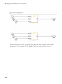
Generated Code Structure for Subsystem Mask Parameters
In the generated code for masked subsystems, the mask parameters map to function
block inputs. The values you specify in the subsystem mask are assigned to these
function block inputs in the generated code.
For example, the following subsystem, Subsystem, contains two instances, Filt1 and
Filt2, of the same masked subsystem.
2-15
2
Mapping Simulink Semantics to Structured Text
The two subsystems, Filt1 and Filt2, have different values assigned to their mask
parameters. In this example, Filt1_Order_Thau is a constant with a value of 5.
2-16
Generated Code Structure for Subsystem Mask Parameters
2-17
2
Mapping Simulink Semantics to Structured Text
Therefore, for the Filt1 subsystem, the Filt1_Order_Thau parameter has a value of 8,
and for the Filt2 subsystem, the Filt1_Order_Thau parameter has a value of 5.
The following generated code shows the Filt1 function block inputs. The
rtp_Filt1_Order_Thau input was generated for the Filt1_Order_Thau mask
parameter.
FUNCTION_BLOCK Filt1
VAR_INPUT
ssMethodType: SINT;
InitV: LREAL;
InitF: BOOL;
Input: LREAL;
rtp_Filt1_Order_Thau: LREAL;
rtp_InitialValue: LREAL;
rtp_Filt1_Order_Enable: BOOL;
END_VAR
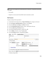
The following generated code is from the FUNCTION_BLOCK Subsystem. The function
block assigns a value of 8 to the rtp_Filt1_Order_Thau input for the i0_Filt1
2-18
Generated Code Structure for Subsystem Mask Parameters
instance, and assigns a value of 5 to the rtp_Filt1_Order_Thau input for the
i1_Filt1 instance.
SS_INITIALIZE:
(* InitializeConditions for Atomic SubSystem: '<S1>/Filt1' *)
i0_Filt1(ssMethodType := SS_INITIALIZE, InitV := In3,
InitF := In2, Input := In1,
rtp_Filt1_Order_Thau := 8.0,
rtp_InitialValue := 0.0,
rtp_Filt1_Order_Enable := TRUE);
Out1 := i0_Filt1.Out;
(* End of InitializeConditions for SubSystem: '<S1>/Filt1' *)
(* InitializeConditions for Atomic SubSystem: '<S1>/Filt2' *)
i1_Filt1(ssMethodType := SS_INITIALIZE, InitV := In6,
InitF := In5, Input := In4,
rtp_Filt1_Order_Thau := 5.0,
rtp_InitialValue := 4.0,
rtp_Filt1_Order_Enable := TRUE);
Out2 := i1_Filt1.Out;
(* End of InitializeConditions for SubSystem: '<S1>/Filt2' *)
SS_STEP:
(* Outputs for Atomic SubSystem: '<S1>/Filt1' *)
i0_Filt1(ssMethodType := SS_OUTPUT, InitV := In3, InitF := In2,
Input := In1, rtp_Filt1_Order_Thau := 8.0,
rtp_InitialValue := 0.0,
rtp_Filt1_Order_Enable := TRUE);
Out1 := i0_Filt1.Out;
(* End of Outputs for SubSystem: '<S1>/Filt1' *)
(* Outputs for Atomic SubSystem: '<S1>/Filt2' *)
i1_Filt1(ssMethodType := SS_OUTPUT, InitV := In6, InitF := In5,
Input := In4, rtp_Filt1_Order_Thau := 5.0,
rtp_InitialValue := 4.0,
rtp_Filt1_Order_Enable := TRUE);
Out2 := i1_Filt1.Out;
(* End of Outputs for SubSystem: '<S1>/Filt2' *)
2-19
2
Mapping Simulink Semantics to Structured Text
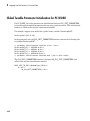
Global Tunable Parameter Initialization for PC WORX
For PC WORX, the coder generates an initialization function, PLC_INIT_PARAMETERS,
to initialize global tunable parameters that are arrays and structures. This initialization
function is called in the top-level initialization method.
For example, suppose your model has a global array variable, ParArrayXLUT:
ParArrayXLUT=[0,2,6,10];
In the generated code, the PLC_INIT_PARAMETERS function contains the following code
to initialize ParArrayXLUT:
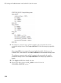
(* parameter initialization function starts *)<br/>
ParArrayXLUT[0] := LREAL#0.0;<br/>
ParArrayXLUT[1] := LREAL#2.0;<br/>
ParArrayXLUT[2] := LREAL#6.0;<br/>
ParArrayXLUT[3] := LREAL#10.0;<br/>
(* parameter initialization function ends *)<br/></div></html>
The PLC_INIT_PARAMETERS function is renamed i0_PLC_INIT_PARAMETERS, and
called in the top-level initialization method:
CASE SINT_TO_INT(ssMethodType) OF<br/>
0: <br/>
i0_PLC_INIT_PARAMETERS();<br/>
2-20
3
Generating Test Bench Code
• “How Test Bench Verification Works” on page 3-2
• “Generated Files” on page 3-3
• “Integrate Generated Code into Custom Code” on page 3-4
• “Generate and Manually Import Test Bench Code” on page 3-5
• “Import and Verify Structured Text Code Automatically” on page 3-8
3
Generating Test Bench Code
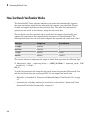
How Test Bench Verification Works
The Simulink PLC Coder software simulates your model and automatically captures
the input and output signals for the subsystem that contains your algorithm. This set
of input and output signal data is the test bench data. The coder also automatically
generates a test bench, or test harness, using the test bench data.
The test bench runs the generated code to verify that the output is functionally and
numerically equivalent to the output from the execution of a Simulink model. The
following table shows how the test bench compares the expected and actual data values.
Data type
Comparison
Error tolerance
integer
absolute
0
boolean
absolute
0
single
relative
0.0001
double
relative
0.00001
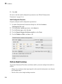
The relative tolerance comparison for single or double data types uses the following logic:
IF ABS(actual_value - expected_value) > (ERROR_TOLERANCE * expected_value) THEN
testVerify := FALSE;
END_IF;
To verify the generated code using the test bench, import the generated Structured Text
and the test bench data into your target IDE. You can import test bench code:
• Manually, as described in “Generate and Manually Import Test Bench Code” on page
3-5.
• Automatically, including running the test bench, as described in “Import and Verify
Structured Text Code Automatically” on page 3-8
3-2
Generated Files
Generated Files
Depending on the target IDE platform, the Simulink PLC Coder software generates code
into one or more files. See “Generate Structured Text from the Model Window” for list of
the target IDE platforms and the possible generated files.
3-3
3
Generating Test Bench Code
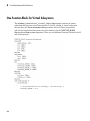
Integrate Generated Code into Custom Code
For the top-level subsystem that has internal state, the generated FUNCTION_BLOCK
code has ssMethodType. ssMethodType is a special input argument that the coder adds
to the input variables section of the FUNCTION_BLOCK section during code generation.
ssMethodType enables you to execute code for Simulink Subsystem block methods such
as initialization and computation steps. The generated code executes the associated
CASE statement based on the value passed in for this argument.
To use ssMethodType with a FUNCTION_BLOCK for your model, in the generated code,
the top-level subsystem function block prototype has one of the following formats:
Has Internal State
ssMethodType Contains...
Yes
The generated function block for the block will have an extra first
parameter ssMethodType of integer type. This extra parameter is in
addition to the function block I/O parameters mapped from Simulink
block I/O ports. To use the function block, first initialize the block by
calling the function block with ssMethodType set to integer constant
SS_INITIALIZE. If the IDE does not support symbolic constants, set
ssMethodType to integer value 0. For each follow-up invocation, call
the function block with ssMethodType set to constant SS_STEP. If
the IDE does not support symbolic constants, set ssMethodType to
integer value 1. These settings cause the function block to initialize
or compute and return output for each time step.
No
The function block interface only has parameters mapped from
Simulink block I/O ports. There is no ssMethodType parameter. To
use the function block in this case, call the function block with I/O
arguments.
For non top-level subsystems, in the generated code, the subsystem function block
prototype has one of the following formats:
3-4
Has Internal State
ssMethodType Contains...
Yes
The function block interface has the ssMethodType parameter. The
generated code might have SS_INITIALIZE, SS_OUTPUT, or other
ssMethodType constants to implement Simulink semantics.
No
The function block interface only has parameters mapped from
Simulink block I/O ports. There is no ssMethodType parameter.
Generate and Manually Import Test Bench Code
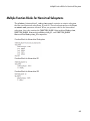
Generate and Manually Import Test Bench Code
This example shows how to generate test bench code using the CoDeSys V2.3 IDE as an
example target IDE.
This example assumes that you have an appropriately configured model from which to
generate Structured Text. Other models configured for Structured Text code generation
are located in the matlabroot\toolbox\plccoder\plccoderdemos folder.
If you do not have the plcdemo_simple_subsystem model open, open it now.
Check that you have connected the inputs and outputs of the subsystem for which you
want to generate the test bench. You can import this test bench with the generated code
to the target IDE to verify that the output is functionally and numerically equivalent to
the output from the execution of a Simulink model.
3-5
3
Generating Test Bench Code
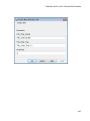
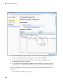
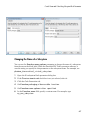
Right-click the Subsystem block and select PLC Code > Options.
The Configuration Parameters dialog box is displayed.
In PLC Code > General options > Target IDE, select your target IDE, for example,
CoDeSys 2.3.
Select the Generate testbench for subsystem check box.
Click Apply.
Click the Generate code button.
3-6
Generate and Manually Import Test Bench Code
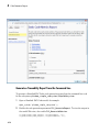
This button:
• Generates Structured Text code (same as the PLC Code > Generate Code for
Subsystem option)
• Generates the test bench for code through Simulink simulation
• Combines the generated code and test bench into model_name.exp (for example,
plcdemo_simple_subsystem.exp)
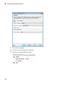
When code generation is complete, a View diagnostics hyperlink appears at the
bottom of the model window. Click this hyperlink to open the Diagnostic Viewer
window.
Click OK.
The Simulink PLC Coder software generates Structured Text code and writes it to
current_folder/plcsrc/plcdemo_simple_subsystem.exp. Depending on the
target IDE, the coder might generate additional supporting files.
Close the model.
bdclose(sys)
See the user manual for your target IDE for information on how to import generated code
into the target IDE.
3-7
3
Generating Test Bench Code
Import and Verify Structured Text Code Automatically
In this section...
“Import and Verify Structured Text to KW-Software MULTIPROG 5.0 and Phoenix
Contact PC WORX 6.0 IDEs Automatically” on page 3-8
“Generate, Automatically Import, and Verify Structured Text” on page 3-9
These topics assume that you have read “Import Structured Text Code Automatically”
on page 1-25. If you have not yet done so, read that topic first. It also assumes that you
are confident that your model produces Structured Text that does not require visual
examination.
If you do not want to run and verify the generated code and want only to import it, see
“Generate and Automatically Import Structured Text Code” on page 1-25.
Import and Verify Structured Text to KW-Software MULTIPROG 5.0 and
Phoenix Contact PC WORX 6.0 IDEs Automatically
Before you can automatically import generated code to this IDE, create an Empty
template. This topic assumes that you have already set your target IDE to KW-Software
MULTIPROG 5.0 or Phoenix Contact PC WORX 6.0.
1
Start the KW-Software MULTIPROG 5.0 or Phoenix Contact PC WORX 6.0 IDE.
2
Select File > Delete Template. Delete any template named Empty, and click OK
when done.
3
Select File > New Project, select Project Wizard, then click OK.
The Project Wizard starts.
a
In the Project Name field, type Empty,
b
In the Project Path field, type or select a path to which you have write
privileges.
c
Click Next.
d
In the remaining wizard dialog boxes, click Next to leave the default selections.
At the end of the wizard, click Finish.
The IDE updates with the new Empty project tree.
3-8
Import and Verify Structured Text Code Automatically
4
In the project, delete everything under the following nodes:
• Logical POUs
• Physical Hardware
5
Check that the project tree has only top-level nodes for Libraries, Data Types,
Logical POUs, and Physical Hardware. There should be no subtree nodes.
6
In the IDE, select File > Save As Template.
7
In Template Name, type Empty.
8
Click OK.
9
Close the IDE interface.
When you are ready, open your model, right-click the Subsystem block, and select one of
the following:
• PLC Code > Generate and Import Code for Subsystem
• PLC Code > Generate, Import, and Verify Code for Subsystem
The coder:
1
Generates the code and test bench.
2
Starts the IDE.
3
Creates a new, empty project using your Empty template.
4
Imports the generated code and test bench in XML file to the IDE.
5
If you selected PLC Code > Generate, Import, and Verify Code for Subsystem,
the IDE also runs the generated code to verify it.
Generate, Automatically Import, and Verify Structured Text
You can generate, automatically import, and run and verify Structured Text code. If
you want only to generate and automatically import Structured Text code, see “Import
Structured Text Code Automatically” on page 1-25 instead.
The following procedure assumes that you have installed your target PLC IDE in a
default location. If you installed the target PLC IDE in a nondefault location, open the
Configuration Parameters dialog box. In the PLC Coder node, set the Target IDE Path
parameter to the installation folder of your PLC IDE. See “Target IDE Path” for more
details.
3-9
3
Generating Test Bench Code
Note: While the automatic import and verification process is in progress, do not touch
your mouse or keyboard. Doing so might disrupt the automatic import or verification
process. You can resume normal operations when the process completes.
If you are working with the KW-Software MULTIPROG 5.0 or Phoenix Contact PC
WORX 6.0 IDE, see “Import and Verify Structured Text to KW-Software MULTIPROG
5.0 and Phoenix Contact PC WORX 6.0 IDEs Automatically” on page 3-8.
1
If you do not have the plcdemo_simple_subsystem model open, open it now.
2
Right-click the Subsystem block and select PLC Code > Generate, Import, and
Verify Code for Subsystem.
The coder then:
3-10
a
Generates the code and test bench.
b
Starts the target IDE.
c
Creates a new project.
d
Imports the generated code and test bench to the new project in the target IDE.
e
On the target IDE, runs the generated code to verify it.
4
Code Generation Reports
• “Information in Code Generation Reports” on page 4-2
• “Create and Use Code Generation Reports” on page 4-4
• “Working with the Static Code Metrics Report” on page 4-16
4
Code Generation Reports
Information in Code Generation Reports
The coder creates and displays a Traceability Report file when you select one or more of
these options:
GUI Option
Command-Line Property
Description
Generate
traceability
report
PLC_GenerateReport
Specify whether to create code
generation report.
Generate
model Web
view
PLC_GenerateWebview
Include the model Web view in
the code generation report to
navigate between the code and
model within the same window.
You can share your model and
generated code outside of the
MATLAB environment.
In the Configuration Parameters dialog box, in the Report panel, you see these options.
Note: You must have a Simulink Report Generator™ license to generate traceability
reports.
The coder provides the traceability report to help you navigate more easily between the
generated code and your source model. When you enable code generation report, the
coder creates and displays an HTML code generation report. You can generate reports
from the Configuration Parameters dialog box or the command line. A typical traceability
report looks something like this figure:
4-2
Information in Code Generation Reports
4-3
4
Code Generation Reports
Create and Use Code Generation Reports
In this section...
“Generate a Traceability Report from Configuration Parameters” on page 4-4
“Keep the Report Current” on page 4-6
“Trace from Code to Model” on page 4-7
“Trace from Model to Code” on page 4-8
“Model Web View in Code Generation Report” on page 4-10
“Generate a Static Code Metrics Report” on page 4-13
“Generate a Traceability Report from the Command Line” on page 4-14
Generate a Traceability Report from Configuration Parameters
To generate a Simulink PLC Coder code generation report from the Configuration
Parameters dialog box:
4-4
1
Verify that the model is open.
2
Open the Configuration Parameters dialog box and navigate to the PLC Code
Generation pane.
3
To enable report generation, select Report > Generate traceability report.
4
Click Apply.
Create and Use Code Generation Reports
5
Click PLC Code Generation > Generate code to initiate code and report
generation. The coder generates HTML report files as part of the code generation
process.
The HTML report appears:
4-5
4
Code Generation Reports
For more information, see:
• “Trace from Code to Model” on page 4-7
• “Trace from Model to Code” on page 4-8
Keep the Report Current
If you generate a code generation report for a model, and subsequently make changes to
the model, the report might become invalid. To keep your code generation report current,
4-6
Create and Use Code Generation Reports
after modifying the source model, regenerate code and the report. If you close and then
reopen a model, regenerate the report.
Trace from Code to Model
You must have already generated code with a traceability report. If not, see “Generate
a Traceability Report from Configuration Parameters” on page 4-4 or “Generate a
Traceability Report from the Command Line” on page 4-14.
To trace generated code to your model:
1
In the generated code HTML report display, look for <S1>/Gain.
S1/Gain
2
In the HTML report window, click a link to highlight the corresponding source
block. For example, in the HTML report shown in the previous figure, you click the
4-7
4
Code Generation Reports
hyperlink for the Gain block (highlighted) to view that block in the model. Clicking
the hyperlink locates and displays the corresponding block in the model editor
window. You can use the same method to trace other block from the HTML report.
Trace from Model to Code
You can select a component at any level of the model with model-to-code traceability. You
can also view the code references to that component in the HTML code generation report.
You can select the following objects for tracing:
• Subsystem
• Simulink block
• MATLAB Function block
• Truth Table block
• State Transition Table block
• Stateflow chart, or the following elements of a Stateflow chart:
• State
• Transition
• Graphical function
• MATLAB function
• Truth table function
You must have already generated code with a traceability report to trace a model
component to the generated code. If not, see “Generate a Traceability Report from
Configuration Parameters” on page 4-4 or “Generate a Traceability Report from the
Command Line” on page 4-14.
4-8
Create and Use Code Generation Reports
To trace a model component to the generated code:
1
In the model window, right-click the component and select PLC Code > Navigate
to Code.
2
Selecting Navigate to Code activates the HTML code generation report. The
following figure shows the result of tracing the Gain block within the subsystem.
In the report, the highlighted tag S1/Gain indicates the beginning of the generated
code for the block. You can use the same method to trace from other Simulink,
Stateflow and MATLAB objects to the generated traceability report.
4-9
4
Code Generation Reports
Model Web View in Code Generation Report
Model Web Views
To review and analyze the generated code, it is helpful to navigate between the code
and model. You can include a Web view of the model within the HTML code generation
report. You can then share your model and generated code outside of the MATLAB
environment. You need a Simulink Report Generator license to include a Web view of the
model in the code generation report.
Browser Requirements for Web Views
Web views require a Web browser that supports Scalable Vector Graphics (SVG). Web
views use SVG to render and navigate models.
You can use the following Web browsers:
• Mozilla® Firefox® Version 1.5 or later, which has native support for SVG. To download
the Firefox browser, go to www.mozilla.com/.
• Apple Safari Web browser
• The Microsoft® Internet Explorer® Web browser with the Adobe® SVG Viewer plug-in.
To download the Adobe SVG Viewer plug-in, go to www.adobe.com/svg/.
Note: Web views do not currently support Microsoft Internet Explorer 9.
Generate HTML Code Generation Report with Model Web View
This example shows how to create an HTML code generation report which includes a
Web view of the model diagram.
4-10
1
Open the plcdemo_simple_subsystem model.
2
Open the Configuration Parameters dialog box and navigate to the Code Generation
pane.
3
To enable report generation, select Report > Create report code generation
report.
4
To enable model web view, select Report > Generate model Web view.
5
Click Apply.
Create and Use Code Generation Reports
The dialog box looks something like this:
6
Click PLC Code Generation > Generate code to initiate code and report
generation. The code generation report for the top model opens in a MATLAB Web
browser.
4-11
4
Code Generation Reports
7
In the left navigation pane, select a source code file. The corresponding traceable
source code is displayed in the right pane and includes hyperlinks.
8
Click a link in the code. The model Web view displays and highlights the
corresponding block in the model.
9
To go back to the code generation report for the top model, at the top of the left
navigation pane, click the Back button until the top model's report is displayed.
For more information about navigating between the generated code and the model
diagram, see:
• “Trace from Code to Model” on page 4-7
4-12
Create and Use Code Generation Reports
• “Trace from Model to Code” on page 4-8
Model Web View Limitations
When you are using the model Web view, the HTML code generation report includes the
following limitations :
• Code is not generated for virtual blocks. In the model Web view, if you click a virtual
block, the code generation report clears highlighting in the source code files.
• Stateflow truth tables, events, and links to library charts are not supported in the
model Web view.
• Searching in the code generation report does not find or highlight text in the model
Web view.
• In a subsystem build, the traceability hyperlinks of the root-level inports and outports
blocks are disabled.
• If you navigate from the actual model diagram (not the model Web view in the
report), to the source code in the HTML code generation report, the model Web view
is disabled and not visible. To enable the model Web view, open the report again, see
“Open Code Generation Report”.
Generate a Static Code Metrics Report
The PLC Coder Static Code Metrics report provides statistics of the generated code.
The report is generated when you select Generate Traceability Report in the
Configuration Parameters dialog box. You can use the Static Code Metrics Report
to evaluate the generated PLC code before implementation in your IDE. For more
information, see “Working with the Static Code Metrics Report” on page 4-16.
The procedure is the same as generating the Traceability Report.
1
Open the Configuration Parameters dialog box and navigate to the PLC Code
Generation pane.
2
To enable report generation, select Report > Generate traceability report.
3
Click Apply.
4
Click PLC Code Generation > Generate code to initiate code and report
generation. The coder generates HTML report files as part of the code generation
process. The Code Metrics Report is shown on the left navigation pane.
4-13
4
Code Generation Reports
Generate a Traceability Report from the Command Line
To generate a Simulink PLC Coder code generation report from the command line code
for the subsystem, plcdemo_simple_subsystem/SimpleSubsystem:
1
Open a Simulink PLC Coder model, for example:
open_system('plcdemo_simple_subsystem');
2
Enable the code generation parameter PLC_GenerateReport. To view the output in
the model Web view, also enable PLC_GenerateWebview:
set_param('plcdemo_simple_subsystem', 'PLC_GenerateReport', 'on');
set_param('plcdemo_simple_subsystem', 'PLC_GenerateWebView', 'on');
4-14
Create and Use Code Generation Reports
3
Generate the code.
generatedfiles = plcgeneratecode('plcdemo_simple_subsystem/SimpleSubsystem')
A traceability report is displayed. In your model, a View diagnostics hyperlink
appears at the bottom of the model window. Click this hyperlink to open the
Diagnostic Viewer window.
If the model Web view is also enabled, that view is displayed.
4-15
4
Code Generation Reports
Working with the Static Code Metrics Report
In this section...
“Workflow for Static Code Metrics Report” on page 4-16
“Report Contents” on page 4-17
“Function Block Information” on page 4-18
You can use the information in the Static Code Metrics Report to assess the generated
code and make model changes before code implementation in your target IDE.
Before starting, you should familiarize yourself with potential code limitations of your
IDE. For example, some IDE’s might have limits on the number of variables or lines of
code in a function block.
For detailed instructions on generating the report, see “Generate a Static Code Metrics
Report” on page 4-13.
Workflow for Static Code Metrics Report
This is the basic workflow for using the Static Code Metrics Report with your model.
4-16
Working with the Static Code Metrics Report
Report Contents
The Static Code Metrics Report is divided into the following sections:
• File Information: Reports high-level information about generated files, such as lines
and lines of code.
• Global Variables: Reports information about global variables defined in the
generated code.
• Global Constants: Reports information about global constants defined in the
generated code.
4-17
4
Code Generation Reports
• Function Block Information: Reports a table of metrics for each function block
generated from your model.
Function Block Information
You can use the information in the Function Block Information table to assess the
generated code prior to implementation in your IDE. The leftmost column of the table
lists function blocks with hyperlinks. Clicking on a function block name will lead you to
the function block location in the generated code. From here, you can trace from the code
to the model. For more information, see “Trace from Code to Model” on page 4-7.
4-18
5
Working with Tunable Parameters in
the Simulink PLC Coder Environment
• “Tunable Parameters” on page 5-2
• “Configure Your Model for Tunable Parameters” on page 5-5
• “Identify Tunable Parameters” on page 5-7
• “Tune Parameters Using Simulink.Parameter Objects” on page 5-11
• “Configure Tunable Parameters Using Configuration Parameters” on page 5-15
5
Working with Tunable Parameters in the Simulink PLC Coder Environment
Tunable Parameters
Block parameters can be either tunable or nontunable. A tunable parameter is a
parameter that you can change while a simulation is running. With the Simulink PLC
Coder software, you can tune parameters:
• From the MATLAB workspace, while the model simulation is running.
• In the IDE, while the generated code is running.
The Simulink PLC Coder software exports tunable parameters as exported symbols and
preserves the names of these parameters in the generated code. It does not mangle these
names. As a result, if you use a reserved IDE keyword as a tunable parameter name, the
code generation might cause compilation errors in the IDE. As a general rule, do not use
IDE keywords as tunable parameter names.
The coder maps tunable parameters in the generated code as listed in the following table:
Target IDE
Parameter Storage Class
SimulinkGlobal
ExportedGlobal ImportedExtern
ImportedExternPointer
CoDeSys 2.3
Local function block Global variable.
variables.
Variable definition
is skipped.
Ignored. If you
set the parameter
to this value, the
software treats
it the same as
ImportedExtern.
CoDeSys 3.3
Local function block Global variable.
variables.
Variable definition
is skipped.
Ignored. If you
set the parameter
to this value, the
software treats
it the same as
ImportedExtern.
CoDeSys 3.5
Local function block Global variable.
variables.
Variable definition
is skipped.
Ignored. If you
set the parameter
to this value, the
software treats
it the same as
ImportedExtern.
5-2
Tunable Parameters
Target IDE
Parameter Storage Class
SimulinkGlobal
ExportedGlobal ImportedExtern
ImportedExternPointer
B&R
Automation
Studio 3.0
Local function block Local function
variable.
block variable
Local function block Ignored. If you
variable.
set the parameter
to this value, the
software treats
it the same as
ImportedExtern.
Beckhoff
TwinCAT 2.11
Local function block Global variable.
variable.
Variable definition
is skipped.
KW-Software
MULTIPROG
5.0
Local function block Local function
variable.
block variable.
Local function block Ignored. If you
variable.
set the parameter
to this value, the
software treats
it the same as
ImportedExtern.
Phoenix
Contact PC
WORX 6.0
Local function block Global variable.
variable.
Variable definition
is skipped.
Ignored. If you
set the parameter
to this value, the
software treats
it the same as
ImportedExtern.
RSLogix 5000
17, 18: AOI
AOI local tags.
AOI input tags.
Ignored. If you
set the parameter
to this value, the
software treats
it the same as
ImportedExtern.
AOI input tags.
Ignored. If you
set the parameter
to this value, the
software treats
it the same as
ImportedExtern.
5-3
5
Working with Tunable Parameters in the Simulink PLC Coder Environment
Target IDE
Parameter Storage Class
SimulinkGlobal
ExportedGlobal ImportedExtern
ImportedExternPointer
RSLogix 5000 Instance fields of
Program tags.
17, 18: Routine program UDT tags.
Variable definition
is skipped.
Siemens
SIMATIC
STEP 7 5.4
Local function block Local function
variable.
block variable.
Local function block Ignored. If you
variable.
set the parameter
to this value, the
software treats
it the same as
ImportedExtern.
Generic
Local function block Global variable.
variable.
Variable definition
is skipped.
Ignored. If you
set the parameter
to this value, the
software treats
it the same as
ImportedExtern.
PLCopen
Local function block Global variable.
variable.
Variable definition
is skipped.
Ignored. If you
set the parameter
to this value, the
software treats
it the same as
ImportedExtern.
5-4
Ignored. If you
set the parameter
to this value, the
software treats
it the same as
ImportedExtern.
Configure Your Model for Tunable Parameters
Configure Your Model for Tunable Parameters
Simulink PLC Coder parameters are inlined and not tunable by default.
To configure a model to enable tunable parameters is:
1
Identify the model parameters that you want to be tunable.
2
Define these parameters in the MATLAB workspace in one of the following ways:
• Create a Simulink.Parameter object and use either the Simulink.Parameter
command-line interface or Model Explorer to configure parameters.
Simulink stores Simulink.Parameter objects outside the model. This action
enables you to share Simulink.Parameter objects between multiple models and
work with referenced models.
• Use the Configuration Parameters dialog box to define parameters,
then configure tunable parameters in the Configuration Parameters
> Optimization > Signals and Parameters > Model Parameter
Configuration dialog box.
Simulink stores specified global tunable parameters using the Configuration
Parameters dialog box with the model. You specify these parameter values in the
MATLAB base workspace. You cannot share these parameters between multiple
models.
This table lists the possible tunable parameters and how you can set them using either
Simulink.Parameter or the Configuration Parameters dialog box. When using
Simulink.Parameter, enter the entire command without hyphens.
Mapping of Tunable
Parameters in Generated
Code
Simulink.Parameter
Local variables in function Simulink.Parameter.block
StorageClass =
‘SimulinkGlobal’
Configuration Parameter Dialog Box
Set Configuration Parameters
> Optimization > Signals
and Parameters > Model
Parameter Configuration
> Storage class to
SimulinkGlobal (Auto)
5-5
5
Working with Tunable Parameters in the Simulink PLC Coder Environment
Mapping of Tunable
Parameters in Generated
Code
Simulink.Parameter
Configuration Parameter Dialog Box
Global variables
Simulink.Parameter.StorageClass =
'ExportedGlobal'
Global constants
Simulink.Parameter.Storage- Set Configuration Parameters
> Optimization > Signals
Class = 'ExportedGlobal'
and Parameters > Model
Simulink.Parameter.Parameter Configuration
CoderInfo.CustomStorageClass> Storage class to
= 'Const'
ExportedGlobal
Set Configuration Parameters
> Optimization > Signals
and Parameters > Model
Parameter Configuration
Simulink.Parameter.> Storage class to
CoderInfo.CustomStorageClassExportedGlobal
= 'Default'
Set Configuration Parameters
> Optimization > Signals
and Parameters > Model
Parameter Configuration >
Storage type qualifier to empty
field (default)
Set Configuration Parameters
> Optimization > Signals
and Parameters > Model
Parameter Configuration >
Storage type qualifier to const
Externally defined
variable
5-6
Simulink.Parameter.StorageClass =
'ImportedExtern'
Set Configuration Parameters
> Optimization > Signals
and Parameters > Model
Parameter Configuration
> Storage class to
ImportedExtern
Identify Tunable Parameters
Identify Tunable Parameters
The model my_plcdemo_tunable_params shows how to configure tunable
parameters. This model is the same as the plcdemo_tunable_params and
plcdemo_tunable_params_slparamobj example models. The difference is that the
example model already has the tunable parameters configured.
Note: The coder does not support tuning parameters of bus data type.
1
In the MATLAB Command Window, create a model to look like the following.
2
Select the Sum, Gain, and Unit Delay blocks and create an atomic subsystem with
inputs U, U1, and U2 and outputs Y, Y1, and Y2. Rename the Subsystem block as
SimpleSubystem. When you are finished, the top model and atomic subsystem model
look like the following model:
5-7
5
Working with Tunable Parameters in the Simulink PLC Coder Environment
3
5-8
Save this subsystem as my_plcdemo_tunable_params.
Identify Tunable Parameters
4
Double-click SimpleSubsystem.
5
The three Gain blocks have the constants that you want to make tunable: K1, K2,
and K3.
Next, define these parameters in the MATLAB workspace.
• If you want to use Simulink.Parameter objects, and use either the
Simulink.Parameter command-line interface or Model Explorer to configure
5-9
5
Working with Tunable Parameters in the Simulink PLC Coder Environment
parameters, see “Tune Parameters Using Simulink.Parameter Objects” on page
5-11.
• If you want to use the Configuration Parameters dialog box, see “Defining
Tunable Parameter Values in the MATLAB Workspace” on page 5-15. Use the
Configuration Parameters dialog box to define parameters, then configure tunable
parameters in the Configuration Parameters > Optimization > Signals and
Parameters > Model Parameter Configuration dialog box.
5-10
Tune Parameters Using Simulink.Parameter Objects
Tune Parameters Using Simulink.Parameter Objects
In this section...
“Work Directly with Simulink.Parameter Objects” on page 5-11
“Work with Simulink.Parameter Objects Using Model Explorer” on page 5-13
Work Directly with Simulink.Parameter Objects
This topic describes how to define tunable parameters in the MATLAB workspace using a
MATLAB script that works with Simulink.Parameter objects.
Note: Alternatively, you can use the Model Explorer to create constants as
Simulink.Parameter and define them. For more information, see “Work with
Simulink.Parameter Objects Using Model Explorer” on page 5-13.
You must have already created the my_plcdemo_tunable_params model or opened
plcdemo_tunable_params or plcdemo_tunable_params_slparamobj and identified
the parameters for tuning. If you have not yet done so, see “Identify Tunable Parameters”
on page 5-7.
1
In the MATLAB base workspace, create a script that defines tunable
parameters. In the MATLAB Command Window, create a MATLAB file, such as
setup_tunable_params.m, that contains the following code. This script creates the
constants K1, K2, and K3 as Simulink.Parameter objects, assigns values, and sets
the storage class for these constants.
% define tunable parameters in base workspace as
% Simulink.Parameter objects
% tunable parameter mapped to local variable
K1 = Simulink.Parameter;
K1.Value = 0.1;
K1.StorageClass = 'SimulinkGlobal';
% tunable parameter mapped to global variable
K2 = Simulink.Parameter;
K2.Value = 0.2;
K2.StorageClass = 'ExportedGlobal';
K2.CoderInfo.CustomStorageClass = 'Default';
5-11
5
Working with Tunable Parameters in the Simulink PLC Coder Environment
% tunable parameter mapped to global const
K3 = Simulink.Parameter;
K3.Value = 0.3;
K3.StorageClass = 'ExportedGlobal';
K3.CoderInfo.CustomStorageClass = 'Const';
5-12
2
In the my_plcdemo_tunable_params model, select File > Model Properties >
Model Properties.
3
In the Model Properties dialog box, on the Callbacks pane, select PreLoadFcn.
4
To run the script at model load time, enter the name of the script that you created,
for example, setup_tunable_params.
5
Click Apply.
6
In the Callbacks pane, select CloseFcn.
7
In the Model close function pane, enter the clear command to clear these
constants. For example:
Tune Parameters Using Simulink.Parameter Objects
clear K1 K2 K3;
When you close the model, this command clears these constants from the MATLAB
workspace.
8
Click Apply, then OK.
9
In the MATLAB Command Window, you can change the parameter values using the
Simulink.Parameter.Value field.
10 When you are done, save the model, and generate and inspect the code.
Work with Simulink.Parameter Objects Using Model Explorer
This topic describes how to define tunable parameters in the MATLAB workspace
using the Model Explorer. Within the Model Explorer, you can create constants as
Simulink.Parameter objects and tune the parameters.
5-13
5
Working with Tunable Parameters in the Simulink PLC Coder Environment
Note: Alternatively, you can use the Simulink.Parameter object command-line
interface to create constants and define them. For more information, see “Work Directly
with Simulink.Parameter Objects” on page 5-11.
1
In the Simulink editor window, select View > Model Explorer.
In the MATLAB Command Window, create a MATLAB file, such as
setup_tunable_params.m, that contains the following code. This script creates the
constants K1, K2, and K3 as Simulink.Parameter objects, assigns values, and sets
the storage class for these constants.
2
In the Model Hierarchy pane, select Base Workspace.
The Contents pane is updated with the contents of the MATLAB base workspace.
3
To create a new Simulink.Parameter object, select Add > Simulink Parameter.
4
In the Dialog pane for the Simulink.Parameter object, edit the Storage class
and Value parameters. Click Apply to save changes.
5
When you are done, save the model, and generate and inspect the code.
For more information about using the Model Explorer to work with data objects, see
“Using the Model Explorer to Create Data Objects”.
5-14
Configure Tunable Parameters Using Configuration Parameters
Configure Tunable Parameters Using Configuration Parameters
In this section...
“Defining Tunable Parameter Values in the MATLAB Workspace” on page 5-15
“Configuring Parameters to Be Tunable” on page 5-17
Defining Tunable Parameter Values in the MATLAB Workspace
This topic describes how to define tunable parameter values in the MATLAB workspace
using the Simulink Model Properties dialog box. Defining tunable parameters in this way
enables the model to automatically define parameters each time that you open the model.
You must have already created the my_plcdemo_tunable_params model or opened
plcdemo_tunable_params and identified the parameters for tuning. If you have not
yet done so, see “Identify Tunable Parameters” on page 5-7.
1
In the my_plcdemo_tunable_params model, select File > Model Properties >
Model Properties.
2
In the Model Properties dialog box, on the Callbacks pane, select PreLoadFcn.
3
In the Model pre-load function pane, enter the three constants K1, K2, and K3.
Assign initial values to them. For example:
K1 = 0.1;
K2 = 0.2;
K3 = 0.3;
5-15
5
Working with Tunable Parameters in the Simulink PLC Coder Environment
4
Click Apply.
5
In the Callbacks pane, select CloseFcn.
6
In the Model close function pane, enter the clear command to clear these
constants. For example:
clear K1 K2 K3;
5-16
Configure Tunable Parameters Using Configuration Parameters
When you close the model, this command clears these constants from the MATLAB
workspace.
7
Click Apply, then OK.
Your next task is to configure these parameters to be tunable. See “Configuring
Parameters to Be Tunable” on page 5-17.
Configuring Parameters to Be Tunable
This topic describes how to configure parameters to be tunable using the Simulink
Configuration Parameters dialog box.
You must have already created the my_plcdemo_tunable_params model or opened
plcdemo_tunable_params and defined the parameters for tuning. If you have not yet
5-17
5
Working with Tunable Parameters in the Simulink PLC Coder Environment
done so, see “Defining Tunable Parameter Values in the MATLAB Workspace” on page
5-15.
You must already be familiar with the tunable parameter properties on the Global
(tunable) parameters pane. For more information, see “Declare Tunable Parameters ”
in the Simulink Coder™ documentation.
This example uses code generated with CoDeSys Version 2.3.
5-18
1
In the model, right-click SimpleSubsystem and select PLC Code > Options.
2
Navigate to Optimization > Signals and Parameters.
3
In the Simulation and code generation section, select the Inline parameters
check box. (This check box is cleared by default.)
4
Click Configure.
Configure Tunable Parameters Using Configuration Parameters
5
In the Model Parameter Configuration dialog box, from the Source list, select
Referenced workspace variables.
6
Use the Ctrl key to select the parameters and click Add to table >> to add them to
the Global (tunable) parameters table.
By default, this dialog box sets all parameters to the SimulinkGlobal (Auto)
storage class. This setting generates code with the tunable parameters set at the
local level. In this case, these parameters appear at the function block level in each
function block that uses the parameter.
You can also optionally set the storage type qualifier for a parameter to const.
7
Click Apply and OK.
8
In the Configuration Parameters dialog box, navigate to PLC Code > General
options.
9
Select the Target IDE and Output Directory settings, then click Generate code.
10 Observe that the VAR section of Function Block SimpleSubsystem defines K1,
K2, and K3.
5-19
5
Working with Tunable Parameters in the Simulink PLC Coder Environment
11 To configure a parameter to be a global variable in the generated code, set the
parameter storage class of K2 to ExportedGlobal. Leave the storage type qualifier
unset.
Some target IDEs do not support the access of global variables. In this case, the
Simulink PLC Coder software uses SimulinkGlobal as the automatic storage class.
To configure a parameter to be a global constant in the generated code, set the
parameter storage class of K3 to ExportedGlobal. Set storage type qualifier to
const.
12 Click Apply and OK, then rebuild the code.
13 Observe that K2 is now in the VAR_GLOBAL section. K3 is in the
VAR_GLOBAL_CONSTANT section.
5-20
Configure Tunable Parameters Using Configuration Parameters
14 To configure a parameter so that you or somebody else can provide it through
external Structured Text, set the parameter storage class of K1 to ImportedExtern.
The coder does not generate a variable declaration for the parameter in the code.
Leave the storage type qualifier unset.
15 Click Apply and OK, then rebuild the code.
16 Observe that K1 does not appear in the VAR section of the generated code. (Compare
to Step 10.)
Note: The Simulink PLC Coder software does not support setting the parameter
storage class to ImportedExternPointer. If you set the parameter to this value,
the software treats it the same as ImportedExtern.
5-21
6
Controlling Generated Code Partitions
• “Function Block Partitioning Guidelines” on page 6-2
• “One Function Block for Atomic Subsystems” on page 6-3
• “One Function Block for Virtual Subsystems” on page 6-4
• “Multiple Function Blocks for Nonvirtual Subsystems” on page 6-5
• “Control Generated Code Using Subsystem Block Parameters” on page 6-6
6
Controlling Generated Code Partitions
Function Block Partitioning Guidelines
The Simulink PLC Coder software converts subsystems to function block units according
to the following rules:
• Generates a function block for the top-level atomic subsystem for which you generate
code.
• Generates a function block for an atomic subsystem whose Function packaging
parameter is set to Nonreusable function or Reusable function.
• Inlines generated code from atomic subsystems, whose Function packaging
parameter is set to Inline, into the function block that corresponds to the nearest
ancestor subsystem. This nearest ancestor cannot be inlined.
These topics use code generated with CoDeSys Version 2.3.
6-2
One Function Block for Atomic Subsystems
One Function Block for Atomic Subsystems
The code for plcdemo_simple_subsystem is an example of generating code with one
function block. The atomic subsystem for which you generate code does not contain other
subsystems.
6-3
6
Controlling Generated Code Partitions
One Function Block for Virtual Subsystems
The plcdemo_hierarchical_virtual_subsystem example contains an atomic
subsystem that has two virtual subsystems, S1 and S2, inlined. A virtual subsystem
does not have the Treat as atomic unit parameter selected. When you generate
code for the hierarchical subsystem, the code contains only the FUNCTION_BLOCK
HierarchicalSubsystem component. There are no additional function blocks for the S1
and S2 subsystems.
6-4
Multiple Function Blocks for Nonvirtual Subsystems
Multiple Function Blocks for Nonvirtual Subsystems
The plcdemo_hierarchical_subsystem example contains an atomic subsystem
that has two nonvirtual subsystems, S1 and S2. Virtual subsystems have the Treat
as atomic unit parameter selected. When you generate code for the hierarchical
subsystem, that code contains the FUNCTION_BLOCK HierarchicalSubsystem,
FUNCTION_BLOCK HierarchicalSubsystem_S1, and FUNCTION_BLOCK
HierarchicalSubsystem_S2 components.
Function Block for Hierarchical Subsystem
Function Block for Hierarchical S1
Function Block for Hierarchical S2
6-5
6
Controlling Generated Code Partitions
Control Generated Code Using Subsystem Block Parameters
You can partition generated code using the following Subsystem block parameters on the
Code Generation tab. See the Subsystem block documentation for details.
• Function packaging
• Function name options
Leave the File name options set to the default, Auto.
Generating Separate Partitions and Inlining Subsystem Code
Use the Function packaging parameter to specify the code format to generate for
an atomic (nonvirtual) subsystem. The Simulink PLC Coder software interprets this
parameter depending on the setting that you choose:
Setting
Coder Interpretation
Auto
Uses the optimal format based on the type
and number of subsystem instances in the
model.
Reusable function, Nonreusable
function
Generates a function with arguments that
allows the subsystem code to be shared by
other instances of it in the model.
Inline
Inlines the subsystem unconditionally.
For example, in the plcdemo_hierarchical_virtual_subsystem, you can:
• Inline the S1 subsystem code by setting Function packaging to Inline. This
setting creates one function block for the parent with the S1 subsystem inlined.
• Create a function block for the S2 subsystem by setting Function packaging to
Reusable function, Auto, or Nonreusable function. This setting creates two
function blocks, one for the parent, one for S2.
6-6
Control Generated Code Using Subsystem Block Parameters
Changing the Name of a Subsystem
You can use the Function name options parameter to change the name of a subsystem
from the one on the block label. When the Simulink PLC Coder generates software, it
uses the string you specify for this parameter as the subsystem name. For example, see
plcdemo_hierarchical_virtual_subsystem:
1
Open the S1 subsystem block parameter dialog box.
2
If the Treat as atomic unit check box is not yet selected, select it.
3
Click the Code Generation tab.
4
Set Function packaging to Nonreusable function.
5
Set Function name options to User specified.
6
In the Function name field, specify a custom name. For example, type
my_own_subsystem.
6-7
6
6-8
Controlling Generated Code Partitions
7
Save the new settings.
8
Generate code for the parent subsystem.
9
Observe the renamed function block.
7
Integrating Externally Defined
Symbols
• “Integrate Externally Defined Symbols” on page 7-2
• “Integrate Custom Function Block in Generated Code” on page 7-3
7
Integrating Externally Defined Symbols
Integrate Externally Defined Symbols
The coder allows you to suppress symbol definitions in the generated code. This
suppression allows you to integrate a custom element, such as user defined function
blocks, function blocks, data types, and named global variable and constants, in place of
one generated from a Simulink subsystem. You must then provide these definitions when
importing the code into the target IDE. You must:
• Define the custom element in the subsystem for which you want to generate code.
• Name the custom element.
• In the Configuration Parameters dialog box, add the name of the custom element
to PLC Code Generation > Symbols > Externally Defined Symbols in the
Configuration Parameters dialog box.
• Generate code.
For a description of how to integrate a custom function block, see “Integrate Custom
Function Block in Generated Code” on page 7-3. For a description of the Externally
Defined Symbols parameter, see “Externally Defined Symbols”.
7-2
Integrate Custom Function Block in Generated Code
Integrate Custom Function Block in Generated Code
To integrate a custom function block, ExternallyDefinedBlock, this procedure uses the
example plcdemo_external_symbols.
1
In a Simulink model, add a MATLAB Function block.
2
Double-click the MATLAB Function block.
3
In the MATLAB editor, minimally define inputs, outputs, and stubs. For example:
function Y = fcn(U,V)
% Stub behavior for simulation. This block
% is replaced during code generation
Y = U + V;
4
Change the MATLAB Function block name to ExternallyDefinedBlock.
5
Create a subsystem from this MATLAB Function block.
6
Complete the model to look like plcdemo_external_symbols.
7-3
7
7-4
Integrating Externally Defined Symbols
7
Open the Configuration Parameters dialog box for the model.
8
Add ExternallyDefinedBlock to PLC Code Generation > Symbols >
Externally Defined Symbols.
9
The plcdemo_external_symbols model also suppresses K1 and InBus. Add these
symbol names to the Externally Defined Symbols field, separated by spaces or
commas. For other settings, see the plcdemo_external_symbols model.
Integrate Custom Function Block in Generated Code
10 Save and close your new model. For example, save it as
plcdemo_external_symbols_mine.
11 Generate code for the model.
12 In the generated code, look for instances of ExternallyDefinedBlock.
The reference of ExternallyDefinedBlock is:
The omission of ExternallyDefinedBlock is:
7-5
8
IDE-Specific Considerations
• “Rockwell Automation RSLogix Considerations” on page 8-2
• “Siemens SIMATIC STEP 7 Considerations” on page 8-4
8
IDE-Specific Considerations
Rockwell Automation RSLogix Considerations
Following are considerations for this target IDE platform.
Add-On Instruction and Function Blocks
The Structured Text concept of function block exists for Rockwell Automation RSLogix
target IDEs as an Add-On instruction (AOI). The Simulink PLC Coder software
generates AOIs for Add-On instruction format, not FUNCTION_BLOCK.
Double-Precision Data Types
The Rockwell Automation RSLogix target IDE does not support double-precision data
types. At code generation, the Simulink PLC Coder converts this data type to singleprecision data types in generated code.
Design your model to use single-precision data type (single) as much as possible instead
of double-precision data type (double). If you must use doubles in your model, the
numerical results produced by the generated Structured Text can differ from Simulink
results. This difference is due to double-single conversion in the generated code.
Unsigned Integer Data Types
The Rockwell Automation RSLogix target IDE does not support unsigned integer data
types. At code generation, the Simulink PLC Coder converts this data type to signed
integer data types in generated code.
Design your model to use signed integer data types (int8, int16, int32) as much as
possible instead of unsigned integer data types (uint8, uint16, uint32). Doing so avoids
overflow issues that unsigned-to-signed integer conversions can cause in the generated
code.
Unsigned Fixed-Point Data Types
In the generated code, Simulink PLC Coder converts fixed-point data types to target
IDE integer data types. Because the Rockwell Automation RSLogix target IDE does not
support unsigned integer data types, do not use unsigned fixed-point data types in the
model. For more information about coder limitations for fixed-point data type support,
see “Fixed-Point Data Type Limitations” on page 10-2.
8-2
Rockwell Automation RSLogix Considerations
Enumerated Data Types
The Rockwell Automation RSLogix target IDE does not support enumerated data types.
At code generation, the Simulink PLC Coder converts this data type to 32–bit signed
integer data type in generated code.
8-3
8
IDE-Specific Considerations
Siemens SIMATIC STEP 7 Considerations
Following are considerations for this target IDE platform.
Double-Precision Floating-Point Data Types
The Siemens SIMATIC STEP 7 target IDE does not support double-precision floatingpoint data types. At code generation, the Simulink PLC Coder converts this data type to
single-precision real data types in the generated code.
Design your model to use single-precision floating-point data type (single) as much as
possible instead of double-precision floating-point data type (double). The Simulink
numerical results for double-precision floating-point data types can differ from the
numerical results produced by the generated Structured Text.
Design your model so that the possible precision loss of numerical results of the
generated code does not change the expected semantics of the model.
int8 and Unsigned Integer Types
The Siemens SIMATIC STEP 7 SCL language does not support int8 and unsigned
integer data types. At code generation, the Simulink PLC Coder converts int8 and
unsigned integer data types to int16 or int32 in the generated code.
Design your model to use int16 and int32 data types as much as possible instead of int8
or unsigned integer data types. The Simulink numerical results using int8 or unsigned
integer data types can differ from the numerical results produced by the generated
Structured Text.
Design your model so that effects of integer data type conversion of the generated code do
not change the expected semantics of the model.
Unsigned Fixed-Point Data Types
In the generated code, Simulink PLC Coder converts fixed-point data types to target IDE
integer data types. Because the Siemens SIMATIC STEP 7 target IDE does not support
unsigned integer data types, do not use unsigned fixed-point data types in the model. For
more information about coder limitations for fixed-point data type support, see “FixedPoint Data Type Limitations” on page 10-2.
8-4
Siemens SIMATIC STEP 7 Considerations
Enumerated Data Types
The Siemens SIMATIC STEP 7 target IDE does not support enumerated data types. The
Siemens SIMATIC STEP 7 converts this data type to 16–bit signed integer data type in
the generated code.
8-5
9
Supported Simulink and Stateflow
Blocks
9
Supported Simulink and Stateflow Blocks
Supported Blocks
For Simulink semantics not supported by Simulink PLC Coder, see “Coder Limitations”.
In this section...
“View Supported Blocks Library” on page 9-2
“Supported Simulink Blocks” on page 9-3
“Supported Stateflow Blocks” on page 9-11
“Blocks With Restricted Support” on page 9-12
View Supported Blocks Library
To view a Simulink library of blocks that the Simulink PLC Coder software supports,
type plclib in the Command Window. The coder can generate Structured Text code for
subsystems that contain these blocks. The library window is displayed.
9-2
Supported Blocks
This library contains two sublibraries, Simulink and Stateflow. Each sublibrary contains
the blocks that you can include in a Simulink PLC Coder model.
Supported Simulink Blocks
The coder supports the following Simulink blocks.
Additional Math & Discrete/Additional Discrete
Transfer Fcn Direct Form II
Transfer Fcn Direct Form II Time Varying
Unit Delay Enabled
9-3
9
Supported Simulink and Stateflow Blocks
Unit Delay Enabled External IC
Unit Delay Enabled Resettable
Unit Delay Enabled Resettable External IC
Unit Delay External IC
Unit Delay Resettable
Unit Delay Resettable External IC
Unit Delay With Preview Enabled
Unit Delay With Preview Enabled Resettable
Unit Delay With Preview Enabled Resettable External RV
Unit Delay With Preview Resettable
Unit Delay With Preview Resettable External RV
Commonly Used Blocks
Inport
Bus Creator
Bus Selector
Constant
Data Type Conversion
Demux
Discrete-Time Integrator
Gain
Ground
Logical Operator
9-4
Supported Blocks
Mux
Product
Relational Operator
Saturation
Scope
Subsystem
Inport
Outport
Sum
Switch
Terminator
Unit Delay
Discontinuities
Coulomb and Viscous Friction
Dead Zone Dynamic
Rate Limiter
Rate Limiter Dynamic
Relay
Saturation
Saturation Dynamic
Wrap To Zero
Discrete
Difference
9-5
9
Supported Simulink and Stateflow Blocks
Discrete Transfer Fcn
Discrete Derivative
Discrete FIR Filter
Discrete Filter
PID Controller
PID Controller (2 DOF)
Discrete State-Space
Discrete-Time Integrator
Integer Delay
Memory
Tapped Delay
Transfer Fcn First Order
Transfer Fcn Lead or Lag
Transfer Fcn Real Zero
Unit Delay
Zero-Order Hold
Logic and Bit Operations
Bit Clear
Bit Set
Bitwise Operator
Compare To Constant
Compare To Zero
9-6
Supported Blocks
Detect Change
Detect Decrease
Detect Increase
Detect Fall Negative
Detect Fall Nonpositive
Detect Rise Nonnegative
Detect Rise Positive
Extract Bits
Interval Test
Interval Test Dynamic
Logical Operator
Shift Arithmetic
Lookup Tables
Dynamic-Lookup
Interpolation Using Prelookup
PreLookup
n-D Lookup Table
Math Operations
Abs
Add
Assignment
Bias
Divide
9-7
9
Supported Simulink and Stateflow Blocks
Dot Product
Gain
Math Function
Matrix Concatenate
MinMax
MinMax Running Resettable
Permute Dimensions
Polynomial
Product
Product of Elements
Reciprocal Sqrt
Reshape
Rounding Function
Sign
Slider Gain
Sqrt
Squeeze
Subtract
Sum
Sum of Elements
Trigonometric Function
Unary Minus
Vector Concatenate
9-8
Supported Blocks
Model Verification
Assertion
Check Discrete Gradient
Check Dynamic Gap
Check Dynamic Range
Check Static Gap
Check Static Range
Check Dynamic Lower Bound
Check Dynamic Upper Bound
Check Input Resolution
Check Static Lower Bound
Check Static Upper Bound
Model-Wide Utilities
DocBlock
Model Info
Ports & Subsystems
Atomic Subsystem
CodeReuse Subsystem
Enabled Subsystem
Enable
Function-Call Subsystem
Subsystem
Inport
9-9
9
Supported Simulink and Stateflow Blocks
Outport
Signal Attributes
Data Type Conversion
Data Type Duplicate
Signal Conversion
Signal Routing
Bus Assignment
Bus Creator
Bus Selector
Data Store Memory
Demux
From
Goto
Goto Tag Visibility
Index Vector
Multiport Switch
Mux
Selector
Sinks
Display
Floating Scope
Scope
Stop Simulation
9-10
Supported Blocks
Terminator
To File
To Workspace
XY Graph
Sources
Constant
Counter Free-Running
Counter Limited
Enumerated Constant
Ground
Pulse Generator
Repeating Sequence Interpolated
Repeating Sequence Stair
User-Defined Functions
MATLAB Function
Fcn
Supported Stateflow Blocks
The coder supports the following Stateflow blocks.
Stateflow
Chart
State Transition Table
Truth Table
9-11
9
Supported Simulink and Stateflow Blocks
Blocks With Restricted Support
Simulink Block Support Exceptions
The Simulink PLC Coder software supports the plclib blocks with the following
exceptions. Also, see for a list of limitations of the software.
If you get unsupported fixed-point type messages during code generation, update
the block parameter. Open the block parameter dialog box. Navigate to the Signal
Attributes and Parameter Attributes tabs. Check that the Output data type and
Parameter data type parameters are not Inherit: Inherit via internal rule.
Set these parameters to either Inherit: Same as input or a desired non-fixed-point
data type, such as double or int8.
Stateflow Chart Exceptions
If you receive a message about consistency between the original subsystem and the Sfunction generated from the subsystem build, and the model contains a Stateflow chart
that contains one or more Simulink functions, use the following procedure to address the
issue:
1
Open the model and double-click the Stateflow chart that causes the issue.
The chart Stateflow Editor dialog box is displayed.
2
Right-click in this dialog box.
3
In the context-sensitive menu, select Properties.
The Chart dialog box is displayed.
4
In the Chart dialog box, navigate to the States When Enabling parameter and
select Held.
5
Click Apply and OK and save the model.
Data Store Memory Block
To generate PLC code for a model that uses a data store memory block, first define a
Simulink.signal object in the base workspace. Then set the data store name to resolve to
that Simulink signal object.
This option is in the Code Generation pane of the Signal Attributes tab in the Data Store
Memory parameters.
9-12
Supported Blocks
For more information see “Data Stores with Data Store Memory Blocks”.
Reciprocal Sqrt Block
The Simulink PLC Coder software does not support the Simulink Reciprocal Sqrt block
signedSqrt and rSqrt functions.
Lookup Table Blocks
Simulink PLC Coder has limited support for lookup table blocks. The coder does not
support:
• Number of dimensions greater than 2
• Cubic spline interpolation method
• Begin index search using a previous index mode
• Cubic spline extrapolation method
Note: The Simulink PLC Coder software does not support the Simulink Lookup Table
Dynamic block. For your convenience, the plclib/Simulink/Lookup Tables library
contains an implementation of a dynamic table lookup block using the Prelookup and
Interpolation Using Prelookup blocks.
9-13
10
Limitations
10
Limitations
Coder Limitations
In this section...
“Current Limitations” on page 10-2
“Fixed-Point Data Type Limitations” on page 10-2
“Multirate Model Limitations” on page 10-4
“Permanent Limitations” on page 10-5
Current Limitations
The Simulink PLC Coder software does not support the following Simulink semantics:
• Complex data types
• Model reference
• Absolute time temporal logic in Stateflow charts. Absolute time temporal logic is
supported for only the Rockwell Automation RSLogix 5000 IDE. For more information
see “Integrate Absolute Time Temporal Logic Code”.
• Stateflow machine-parented data and events
• Limited support for math functions. The coder does not support the following
functions: tanh, cosh, sinh, rand.
• Merge block
• Signal and state storage classes
• Virtual buses at the input ports of the top-level Atomic Subsystem block
• For Each Subsystem block
• Variable-size signals
• Nonfinite data, for example NaN or Inf
• Objects defined in the Simulink data dictionary, including model parameters, signals
and state objects.
Fixed-Point Data Type Limitations
Simulink PLC Coder software supports the fixed-point data type. To generate code for
fixed-point data types, configure block and model parameters as described in this topic.
10-2
Coder Limitations
Note: If you do not configure the blocks and models as directed, the generated Structured
Text might:
• Not compile.
• Compile, but return results that differ from the simulation results.
Block Parameters
Properly configure block parameters:
1
If the block in the subsystem has a Signal Attributes tab, navigate to that tab.
2
For the Integer rounding mode parameter, select Round.
3
Clear the Saturate on integer overflow check box.
4
For the Output data type parameter, select a fixed-point data type.
5
Click the Data Type Assistant button.
6
For the Word length parameter, enter 8, 16, or 32.
7
For the Mode parameter, select Fixed point.
8
For the Scaling parameter, select Binary point.
10-3
10
Limitations
9
Click OK.
Be sure to edit the model configuration parameters (see “Model Configuration
Parameters” on page 10-4).
Model Configuration Parameters
Properly configure model configuration parameters:
1
In model Configuration Parameters dialog box, click the Hardware
Implementation node.
2
For the Device vendor parameter, select Generic.
3
For the Device type, select Custom.
4
For the Signed integer division rounds to, select Zero.
5
For the Number of bits, set char to 16.
Multirate Model Limitations
To generate Structured Text from a multirate model, you must configure the model as
follows:
• Change any continuous time input signals in the top-level subsystem to use discrete
fixed sample times.
• For the solver, select single-tasking execution.
10-4
Coder Limitations
The following target IDEs are not supported for multirate model code generation:
• Rockwell Automation RSLogix 5000 AOI
• Siemens SIMATIC STEP 7
• B&R Automation Studio
When you deploy code generated from a multirate model, you must run the code at the
fundamental sample rate.
Permanent Limitations
The Structured Text language has inherent restrictions. As a result, the Simulink PLC
Coder software has the following restrictions:
• The Simulink PLC Coder software supports code generation only for atomic
subsystems.
• The Simulink PLC Coder software supports automatic, inline, or reusable function
packaging for code generation. Nonreusable function packaging is not supported.
• No blocks that require continuous time semantics. This restriction includes
continuous integrators, zero-crossing blocks, physical modeling blocks, and so on.
• No pointer data types.
• No recursion (including recursive events).
10-5
11
Functions — Alphabetical List
11
Functions — Alphabetical List
plccoderdemos
Product examples
Syntax
plccoderdemos
Description
plccoderdemos displays the Simulink PLC Coder examples.
Examples
Display Simulink PLC Coder examples.
plccoderdemos
See Also
plcopenconfigset
11-2
plccoderpref
plccoderpref
Manage user preferences
Syntax
plccoderpref
plccoderpref('plctargetide')
plccoderpref('plctargetide', preference_value)
plccoderpref('plctargetide', 'default')
plccoderpref('plctargetidepaths')
plccoderpref('plctargetidepaths','default')
Description
plccoderpref displays the current set of user preferences, including the default target
IDE.
plccoderpref('plctargetide') returns the current default target IDE. This
default can be the target IDE set previously, or the factory default. The factory default is
'codesys23'.
plccoderpref('plctargetide', preference_value) sets the default target
IDE to the one that you specify in preference_value. This command sets the
preference_value to persist as the default target IDE for future MATLAB sessions.
plccoderpref('plctargetide', 'default') sets the default target IDE to the
factory default target IDE ('codesys23').
plccoderpref('plctargetidepaths') returns a 1-by-1 structure of the installation
paths of supported target IDEs.
plccoderpref('plctargetidepaths','default') sets the contents of the 1-by-1
structure of the installation paths to the default values.
11-3
11
Functions — Alphabetical List
Input Arguments
plctargetide
String directive that specifies the default target IDE.
Value
Description
codesys23
3S-Smart Software Solutions CoDeSys Version
2.3 (default) target IDE
codesys33
3S-Smart Software Solutions CoDeSys Version
3.3 target IDE
codesys35
3S-Smart Software Solutions CoDeSys Version
3.5 target IDE
brautomation30
B&R Automation Studio 3.0 target IDE
twincat211
Beckhoff TwinCAT 2.11 target IDE
multiprog50
KW-Software MULTIPROG 5.0 target IDE
pcworx60
Phoenix Contact PC WORX 6.0
rslogix5000
Rockwell Automation RSLogix 5000 Series target
IDE for AOI format
rslogix5000_routine
Rockwell Automation RSLogix 5000 Series target
IDE for routine format
step7
Siemens SIMATIC STEP 7 Version 5 target IDE
plcopen
PLCopen XML target IDE
generic
Generic target IDE
Default: codesys23
plctargetidepaths
String that specifies the target IDE installation path. Contains a 1-by-1 structure of the
installation paths of supported target IDEs.
codesys23: 'C:\Program Files\3S Software'
codesys33: 'C:\Program Files\3S CoDeSys'
codesys35: 'C:\Program Files\3S CoDeSys'
rslogix5000: 'C:\Program Files\Rockwell Software'
rslogix5000_routine: 'C:\Program Files\Rockwell Software'
brautomation30: 'C:\Program Files\BrAutomation'
11-4
plccoderpref
multiprog50: 'C:\Program Files\KW-Software\MULTIPROG 5.0'
pcworx60: 'C:\Program Files\Phoenix Contact\Software Suite 150'
step7: 'C:\Program Files\Siemens'
plcopen: ''
twincat211: 'C:\TwinCAT'
generic: ''
default
String that sets your preferences to the factory default.
Examples
Return the current default target IDE.
plccoderpref('plctargetide')
Set rslogix5000 as the new default target IDE.
plccoderpref('plctargetide', 'rslogix5000')
Assume that you have previously changed the installation path of the CoDeSys 2.3 target
IDE. Return the current target IDE installation paths.
codesys23:
codesys33:
codesys35:
rslogix5000:
rslogix5000_routine:
brautomation30:
multiprog50:
pcworx60:
step7:
plcopen:
twincat211:
generic:
'C:\Program
'C:\Program
'C:\Program
'C:\Program
Files2\3S-Software\CoDeSys\v2.3
Files\3S CoDeSys'
Files\3S CoDeSys'
Files\Rockwell Software'
'C:\Program Files\Rockwell Software'
'C:\Program Files\BrAutomation'
'C:\Program Files\KW-Software\MULTIPROG 5.0'
'C:\Program Files\Phoenix Contact\Software Suite 150'
'C:\Program Files\Siemens'
''
'C:\TwinCAT'
''
Set the installation path of all target IDEs, including CoDeSys 2.3, to factory default.
» plccoderpref('plctargetidepaths','default')
ans =
codesys23:
codesys33:
codesys35:
rslogix5000:
rslogix5000_routine:
brautomation30:
'C:\Program
'C:\Program
'C:\Program
'C:\Program
'C:\Program
'C:\Program
Files\3S Software'
Files\3S CoDeSys'
Files\3S CoDeSys'
Files\Rockwell Software'
Files\Rockwell Software'
Files\BrAutomation'
11-5
11
Functions — Alphabetical List
multiprog50:
pcworx60:
step7:
plcopen:
twincat211:
generic:
'C:\Program Files\KW-Software\MULTIPROG 5.0'
'C:\Program Files\Phoenix Contact\Software Suite 150'
'C:\Program Files\Siemens'
''
'C:\TwinCAT'
''
More About
Tips
Use the Simulink Configuration Parameters dialog box to change the installation path of
a target IDE (Target IDE Path).
11-6
plcgeneratecode
plcgeneratecode
Generate Structured Text for subsystem
Syntax
generatedfiles = plcgeneratecode(subsystem)
Description
generatedfiles = plcgeneratecode(subsystem) generates Structured Text for
the specified atomic subsystem in a model. subsystem is the fully qualified path name of
the atomic subsystem. generatedfiles is a cell array of the generated file names. You
must first load or start the model.
Examples
Generate code for the subsystem, plcdemo_simple_subsystem/SimpleSubsystem.
plcdemo_simple_subsystem
generatedfiles = plcgeneratecode('plcdemo_simple_subsystem/SimpleSubsystem')
See Also
plcopenconfigset
11-7
11
Functions — Alphabetical List
plcopenconfigset
Open Configuration Parameters dialog box for subsystem
Syntax
plcopenconfigset(subsystem)
Description
plcopenconfigset(subsystem) opens the Configuration Parameters dialog box for
the specified atomic subsystem in the model. subsystem is the fully qualified path name
of the atomic subsystem.
Examples
Open the Configuration Parameters dialog box for the subsystem,
plcdemo_simple_subsystem/SimpleSubsystem.
plcdemo_simple_subsystem
plcopenconfigset('plcdemo_simple_subsystem/SimpleSubsystem')
See Also
plcgeneratecode
11-8
12
Configuration Parameters for
Simulink PLC Coder Models
• “PLC Coder: General” on page 12-2
• “PLC Coder: Comments” on page 12-10
• “PLC Coder: Optimization” on page 12-15
• “PLC Coder: Symbols” on page 12-20
• “PLC Coder: Report” on page 12-26
12
Configuration Parameters for Simulink PLC Coder Models
PLC Coder: General
In this section...
“PLC Coder: General Tab Overview” on page 12-3
“Target IDE” on page 12-4
“Target IDE Path” on page 12-6
“Code Output Directory” on page 12-8
“Generate testbench for subsystem” on page 12-9
12-2
PLC Coder: General
PLC Coder: General Tab Overview
Set up general information about generating Structured Text code to download to target
PLC IDEs.
Configuration
To enable the Simulink PLC Coder options pane, you must:
1
Create a model.
2
Add either an Atomic Subsystem block, or a Subsystem block for which you have
selected the Treat as atomic unit check box.
3
Right-click the subsystem block and select PLC Code > Options.
Tip
In addition to configuring parameters for the Simulink PLC Coder model, you can
also use this dialog box to generate Structured Text code and test bench code for the
Subsystem block.
See Also
“Prepare Model for Structured Text Generation”
“Generate Structured Text from the Model Window”
12-3
12
Configuration Parameters for Simulink PLC Coder Models
Target IDE
Select the target IDE in which to generate code.
Settings
Default: 3S CoDeSys 2.3
3S CoDeSys 2.3
Generates Structured Text (IEC 61131-3) code for 3S-Smart Software Solutions
CoDeSys Version 2.3.
3S CoDeSys 3.3
Generates Structured Text code in PLCopen XML for 3S-Smart Software Solutions
CoDeSys Version 3.3.
3S CoDeSys 3.5
Generates Structured Text code in PLCopen XML for 3S-Smart Software Solutions
CoDeSys Version 3.5.
B&R Automation Studio 3.0
Generates Structured Text code for B&R Automation Studio 3.0.
Beckhoff TwinCAT 2.11
Generates Structured Text code for Beckhoff TwinCAT 2.11 software.
KW-Software MULTIPROG 5.0
Generates Structured Text code in PLCopen XML for KW-Software MULTIPROG
5.0.
Phoenix Contact PC WORX 6.0
Generates Structured Text code in PLCopen XML for Phoenix Contact PC WORX 6.0.
Rockwell RSLogix 5000: AOI
Generates Structured Text code for Rockwell Automation RSLogix 5000 using AddOn Instruction (AOI) constructs.
Rockwell RSLogix 5000: Routine
Generates Structured Text code for Rockwell Automation RSLogix 5000 routine
constructs.
Siemens SIMATIC Step 7 5.4
Generates Structured Text code for Siemens SIMATIC STEP 7 5.4.
12-4
PLC Coder: General
Generic
Generates a pure Structured Text file. If the target IDE that you want is not
available for the Simulink PLC Coder product, consider generating and downloading
a generic Structured Text file.
PLCopen XML
Generates Structured Text code formatted using PLCopen XML standard.
Bosch Rexroth Indraworks
Generates Structured Text code for Rexroth IndraWorks version 13V12 IDE.
OMRON Sysmac Studio
Generates Structured Text code for OMRON® Sysmac® Studio Version 1.04, 1.05, or
1.09.
Tip
• Rockwell Automation RSLogix 5000 routines represent the model hierarchy using
hierarchical user-defined types (UDTs). UDT types preserve model hierarchy in the
generated code.
• The coder generates code for reusable subsystems as separate routine instances.
These subsystems access instance data in program tag fields.
Command-Line Information
Parameter: PLC_TargetIDE
Type: string
Value: 'codesys23' | 'codesys33' | 'codesys35' | 'rslogix5000' |
'rslogix5000_routine' | 'brautomation30' | 'multiprog50' | 'pcworx60' |
'step7' | 'plcopen' | 'twincat211' | 'generic' | 'indraworks' | 'omron'
Default: 'codesys23'
See Also
“Generate Structured Text from the Model Window”
12-5
12
Configuration Parameters for Simulink PLC Coder Models
Target IDE Path
Enter target IDE installation path. The listed path is the factory default for the Target
IDE entry.
Settings
Default: C:\Program Files\3S Software
C:\Program Files\3S Software
Factory default installation path for 3S-Smart Software Solutions CoDeSys software
Version 2.3.
C:\Program Files\3S CoDeSys
Factory default installation path for 3S-Smart Software Solutions CoDeSys software
Version 3.3..
C:\Program Files\BrAutomation
Factory default installation path for B&R Automation Studio 3.0 software.
C:\TwinCAT
Factory default installation path for Beckhoff TwinCAT 2.11 software.
C:\Program Files\KW-Software\MULTIPROG 5.0
Factory default installation path for KW-Software MULTIPROG 5.0 software.
C:\Program Files\Phoenix Contact\Software Suite 150
Factory default installation path for Phoenix Contact PC WORX 6.0 software.
C:\Program Files\Rockwell Software
Factory default installation path for Rockwell Automation RSLogix 5000 software.
C:\Program Files\Siemens
Factory default installation path for Siemens SIMATIC STEP 7 5.4 software.
Tip
• The value of this parameter changes when you change the Target IDE value.
• If you right-click the Subsystem block, the PLC Code > Generate and Import
Code for Subsystem command uses this value to import generated code.
• If your target IDE installation is standard, do not edit this parameter. Leave it as the
default value.
12-6
PLC Coder: General
• If your target IDE installation is nonstandard, edit this value to specify the actual
installation path.
• If you change the path and click Apply, the changed path remains for that target IDE
for other models and between MATLAB sessions. To reinstate the factory default, use
the command:
plccoderpref('plctargetidepaths','default')
Command-Line Information
See plccoderpref.
See Also
“Import Structured Text Code Automatically”
12-7
12
Configuration Parameters for Simulink PLC Coder Models
Code Output Directory
Enter a path to the target folder into which code is generated.
Settings
Default: plcsrc subfolder in your working folder
Command-Line Information
Parameter: PLC_OutputDir
Type: string
Value: string
Default: 'plcsrc'
See Also
“Generate Structured Text from the Model Window”
12-8
PLC Coder: General
Generate testbench for subsystem
Specify the generation of test bench code for the subsystem.
Settings
Default: off
On
Enables generation of test bench code for subsystem.
Disables generation of test bench code for subsystems.
Tips
If you right-click the Subsystem block and choose PLC Code > Generate and Import
Code for Subsystem, the software also generates the test bench for the subsystem,
regardless of the setting of the Generate testbench for subsystem check box.
Dependency
This parameter is disabled if your model has absolute time temporal logic.
Note: The Simulink PLC Coder software supports absolute time temporal logic in
Stateflow charts for the Rockwell Automation RSLogix 5000 IDE.
Command-Line Information
Parameter: PLC_GenerateTestbench
Type: string
Value: 'on' | 'off'
Default: 'off'
See Also
“Generate Structured Text from the Model Window”
12-9
12
Configuration Parameters for Simulink PLC Coder Models
PLC Coder: Comments
In this section...
“Comments Overview” on page 12-11
“Include comments” on page 12-11
“Include block description” on page 12-12
“Simulink block / Stateflow object comments” on page 12-13
“Show eliminated blocks” on page 12-14
12-10
PLC Coder: Comments
Comments Overview
Control the comments that the Simulink PLC Coder software automatically creates and
inserts into the generated code.
See Also
“Generate Structured Text from the Model Window”
Include comments
Specify which comments are in generated files.
Settings
Default: on
On
Places comments in the generated files based on the selections in the Auto
generated comments pane.
Off
Omits comments from the generated files.
Command-Line Information
Parameter: PLC_RTWGenerateComments
Type: string
Value: 'on' | 'off'
Default: 'on'
See Also
“Generate Structured Text from the Model Window”
12-11
12
Configuration Parameters for Simulink PLC Coder Models
Include block description
Specify which block description comments are in generated files.
Settings
Default: on
On
Places comments in the generated files based on the contents of the block properties
General tab.
Off
Omits block descriptions from the generated files.
Command-Line Information
Parameter: PLC_PLCEnableBlockDescription
Type: string
Value: 'on' | 'off'
Default: 'on'
See Also
“Generate Structured Text from the Model Window”
12-12
PLC Coder: Comments
Simulink block / Stateflow object comments
Specify whether to insert Simulink block and Stateflow object comments.
Settings
Default: on
On
Inserts automatically generated comments that describe block code and objects. The
comments precede that code in the generated file.
Off
Suppresses comments.
Command-Line Information
Parameter: PLC_RTWSimulinkBlockComments
Type: string
Value: 'on' | 'off'
Default: 'on'
See Also
“Generate Structured Text from the Model Window”
12-13
12
Configuration Parameters for Simulink PLC Coder Models
Show eliminated blocks
Specify whether to insert eliminated block comments.
Settings
Default: off
On
Inserts statements in the generated code from blocks eliminated as the result of
optimizations (such as parameter inlining).
Off
Suppresses statements.
Command-Line Information
Parameter: PLC_RTWShowEliminatedStatement
Type: string
Value: 'on' | 'off'
Default: 'off'
See Also
“Generate Structured Text from the Model Window”
12-14
PLC Coder: Optimization
PLC Coder: Optimization
In this section...
“Optimization Overview” on page 12-15
“Signal storage reuse” on page 12-16
“Remove code from floating-point to integer conversions that wraps out-of-range values”
on page 12-18
“Loop unrolling threshold” on page 12-19
Optimization Overview
Select the code generation optimization settings.
See Also
“Generate Structured Text from the Model Window”
12-15
12
Configuration Parameters for Simulink PLC Coder Models
Signal storage reuse
Reuse signal memory.
Settings
Default: on
On
Simulink PLC Coder software reuses memory buffers allocated to store block input
and output signals, reducing the memory requirement of your real-time program.
Off
Simulink PLC Coder software allocates a separate memory buffer for each block's
outputs. This allocation makes block outputs global and unique, which in many cases
significantly increases RAM and ROM usage.
Tips
• This option applies only to signals with storage class Auto.
• Signal storage reuse can occur among only signals that have the same data type.
• Clearing this option can substantially increase the amount of memory required to
simulate large models.
• Clear this option if you need to:
• Debug a C-MEX S-function.
• Use a Floating Scope or a Display block with the Floating display option selected
to inspect signals in a model that you are debugging.
• If Signal storage reuse is enabled and you attempt to use a Floating Scope or
floating Display block to display a signal whose buffer has been reused, Simulink PLC
Coder software opens an error dialog.
Command-Line Information
Parameter:PLC_PLCEnableVarReuse
Type: string
Value: 'on' | 'off'
Default: 'on'
12-16
PLC Coder: Optimization
See Also
“Generate Structured Text from the Model Window”
12-17
12
Configuration Parameters for Simulink PLC Coder Models
Remove code from floating-point to integer conversions that wraps outof-range values
Enable code removal for efficient casts.
Settings
Default: on
On
Simulink PLC Coder software removes code from floating-point to integer
conversions.
Off
Simulink PLC Coder software does not remove code from floating-point to integer
conversions.
Tips
Use this parameter to optimize code generation.
Command-Line Information
Parameter: PLC_PLCEnableEfficientCast
Type: string
Value: 'on' | 'off'
Default: 'on'
See Also
“Generate Structured Text from the Model Window”
12-18
PLC Coder: Optimization
Loop unrolling threshold
Specify the minimum signal or parameter width for which a for loop is generated.
Settings
Default: 5
Specify the array size at which the code generator begins to use a for loop instead of
separate assignment statements to assign values to the elements of a signal or parameter
array.
When there are perfectly nested loops, the code generator uses a for loop if the product
of the loop counts for all loops in the perfect loop nest is greater than or equal to the
threshold.
Command-Line Information
Parameter: PLC_RollThreshold
Type: string
Value: any valid value
Default: '5'
See Also
“Generate Structured Text from the Model Window”
12-19
12
Configuration Parameters for Simulink PLC Coder Models
PLC Coder: Symbols
In this section...
“Symbols Overview” on page 12-21
“Maximum identifier length” on page 12-22
“Use the same reserved names as Simulation Target” on page 12-23
“Reserved names” on page 12-24
“Externally Defined Symbols” on page 12-25
12-20
PLC Coder: Symbols
Symbols Overview
Select the automatically generated identifier naming rules.
See Also
“Generate Structured Text from the Model Window”
12-21
12
Configuration Parameters for Simulink PLC Coder Models
Maximum identifier length
Specify the maximum number of characters in generated function, type definition, and
variable names.
Settings
Default: 31
Minimum: 31
Maximum: 256
You can use this parameter to limit the number of characters in function, type definition,
and variable names. Many target IDEs have their own restrictions. The Simulink PLC
Coder software complies with target IDE limitations.
Command-Line Information
Parameter: PLC_RTWMaxIdLength
Type: int
Value: 31 to 256
Default: 31
See Also
“Generate Structured Text from the Model Window”
12-22
PLC Coder: Symbols
Use the same reserved names as Simulation Target
Specify whether to use the same reserved names as those specified in the Simulation
Target > Symbols pane.
Settings
Default: off
On
Enables using the same reserved names as those specified in the Simulation Target
> Symbols pane pane.
Off
Disables using the same reserved names as those specified in the Simulation
Target > Symbols pane pane.
Command-Line Information
Parameter: PLC_RTWUseSimReservedNames
Type: string
Value: 'on' | 'off'
Default: 'off'
See Also
“Generate Structured Text from the Model Window”
12-23
12
Configuration Parameters for Simulink PLC Coder Models
Reserved names
Enter the names of variables or functions in the generated code that you do not want to
be used.
Settings
Default: ( )
This action changes the names of variables or functions in the generated code to avoid
name conflicts with identifiers in custom code. Reserved names must be shorter than 256
characters.
Tips
• Start each reserved name with a letter or an underscore.
• Each reserved name must contain only letters, numbers, or underscores.
• Separate the reserved names using commas or spaces.
Command-Line Information
Parameter: PLC_RTWReservedNames
Type: string
Value: string
Default: ''
See Also
“Generate Structured Text from the Model Window”
12-24
PLC Coder: Symbols
Externally Defined Symbols
Specify the names of identifiers for which you want to suppress definitions.
Settings
Default: ( )
This action suppresses the definition of identifiers, such as those for function blocks,
variables, constants, and user types in the generated code. This suppression allows the
generated code to refer to these identifiers. When you import the generated code into the
PLC IDE, you must provide these definitions.
Tips
• Start each name with a letter or an underscore.
• Each name must contain only letters, numbers, or underscores.
• Separate the names using spaces or commas.
Command-Line Information
Parameter: PLC_ExternalDefinedNames
Type: string
Value: string
Default: ''
See Also
• “Generate Structured Text from the Model Window”
• “Integrate Externally Defined Symbols”
• Integrating User Defined Function Blocks, Data Types, and Global
Variables into Generated Structured Text
12-25
12
Configuration Parameters for Simulink PLC Coder Models
PLC Coder: Report
In this section...
“Generate traceability report” on page 12-26
“Generate model Web view” on page 12-27
Generate traceability report
Specify whether to create a code generation report.
Settings
Default: off
On
Creates code generation report as HTML file.
Off
Suppresses creation of code generation report.
Command-Line Information
Parameter: PLC_GenerateReport
Type: string
Value: 'on' | 'off'
Default: 'off'
See Also
“Generate Structured Text from the Model Window”
12-26
PLC Coder: Report
Generate model Web view
Include the model Web view in the code generation report to navigate between the code
and the model within the same window. You can share your model and generated code
outside of the MATLAB environment. You need a Simulink Report Generator license to
include a Web view of the model in the code generation report.
Settings
Default: Off
On
Include model Web view in the code generation report.
Off
Omit model Web view in the code generation report.
Command-Line Information
Parameter: PLC_GenerateWebView
Type: string
Value: 'on' | 'off'
Default: 'off'
See Also
“Generate Structured Text from the Model Window”
12-27