1
ALPHA
MICROSYSTEMS
RIGHT. FROM THE START.
ALPHA
MICROSYSTEMS
RIGHT. FROM THE START.
ALPHA
MICROSYSTEMS
RIGHT. FROM THE START.
ALPHA
MICROSYSTEMS
RIGHT. FROM THE START.
ALPHA
MICROSYSTEMS
RIGHT. FROM THE START.
ALPHA
MICROSYSTEMS
RIGHT. FROM THE START.
ALPHA
MICROSYSTEMS
RIGHT. FROM THE START.
ALPHA
MICROSYSTEMS
RIGHT. FROM THE START.
ALPHA
MICROSYSTEMS
RIGHT. FROM THE START.
ALPHA
MICROSYSTEMS
RIGHT. FROM THE START.
ALPHA
MICROSYSTEMS
RIGHT. FROM THE START.
ALPHA
MICROSYSTEMS
RIGHT. FROM THE START.
ALPHA
MICROSYSTEMS
RIGHT. FROM THE START.
AlphaNET
Installation Guide
DSM-00064-05
© 1996 Alpha Microsystems
REVISIONS INCORPORATED
REVISION
DATE
00
March 1989
01
July 1990
02
November 1991
03
February 1995
04
June 1996
05
September 1996
AlphaNET Installation Guide
To re-order this document, request part number DSO-00064-00.
This document applies to AlphaNET version 2.4 and later.
The information contained in this manual is believed to be accurate and reliable. However, no responsibility
for the accuracy, completeness or use of this information is assumed by Alpha Microsystems.
This document may contain references to products covered under U.S. Patent Number 4,530,048.
The following are registered trademarks of Alpha Microsystems, Santa Ana, CA 92799:
AMIGOS
AlphaBASIC
AlphaFORTRAN 77
AlphaMATE
AlphaWRITE
VIDEOTRAX
AMOS
AlphaCALC
AlphaLAN
AlphaNET
CASELODE
Alpha Micro
AlphaCOBOL
AlphaLEDGER
AlphaPASCAL
OmniBASIC
AlphaACCOUNTING
AlphaDDE
AlphaMAIL
AlphaRJE
VER-A-TEL
The following are trademarks of Alpha Microsystems, Santa Ana, CA 92799:
AlphaBASIC PLUS
AlphaDDE
inFront/am
AlphaVUE
AlphaConnect
ESP
AM-PC
DART
MULTI
All other copyrights and trademarks are the property of their respective holders.
ALPHA MICROSYSTEMS
2722 S. Fairview St.
P.O. Box 25059
Santa Ana, CA 92799
AMTEC
inSight/am
Table of Contents
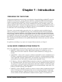
CHAPTER 1 - INTRODUCTION
PREPARING FOR THE FUTURE
ALPHA MICRO COMMUNICATIONS PRODUCTS
ABOUT THIS BOOK
CHAPTER 2 - BUILDING A SIMPLE NETWORK
STEPS TO BUILDING A NETWORK
1. Download AlphaNET Software
2. Enter the Product Installation Code
3. Install the Required Network Hardware
Installing the Hardware
4. Create a Network Initialization File
DRIVER=
NETWORK=
GROUP=
NODE=
NODECHECK=
NODECOUNT=
GROUPCOUNT=
NAME=
DEVICEADDRESS=
5. Create a Network Ersatz File
6. Create a SYSNAM.DAT File
7. Modify the System Initialization Command File
8. Create a NETSER.JIN File
9. Create a VTSER.JIN File
TESTING THE NETWORK
CHAPTER 3 - INSTALLING THE ALPHANET SOFTWARE
OVERVIEW OF THE SOFTWARE INSTALLATION
LOADING THE ALPHANET SOFTWARE
Installing the Product Installation Code
Reviewing Your PIC
CREATING THE SYSNAM.DAT FILE
UPDATING THE SYSTEM INITIALIZATION FILE
Modifying and Testing the TEST.INI File
Increasing the Number of Available Jobs
Adding the NETSER Background Job
AlphaNET Installation Guide, Revision 05
1-1
1-1
1-1
1-2
2-1
2-1
2-1
2-2
2-2
2-2
2-3
2-4
2-4
2-4
2-4
2-5
2-5
2-5
2-5
2-5
2-5
2-6
2-7
2-10
2-10
2-11
3-1
3-1
3-1
3-2
3-2
3-2
3-3
3-3
3-3
3-4
Page ii
Table of Contents
Setting Up Sharable Memory
Adding the VTSER Background Job
VTSER and Network Security
TDVDEF (AMOS 2.1 and Later Only)
Allocating Message Buffers with MSGINI
Initializing the Remote Procedure Call System
Defining a Network
Defining Ersatz Names for Your Network
Turning on the Network
A Sample Initialization File
ETHERNET TYPE 2 VIRTUAL TERMINAL CONNECTIONS
Why Use Type 2 Connections?
Type 2 Virtual Terminal Restrictions
TRMDEF Statement (Type 2 CONECT Support)
Creating Communication Zone (Type 2 CONECT Support)
TESTING THE NEW INITIALIZATION COMMAND FILE
DETERMINING YOUR CPU ID NUMBER
CHAPTER 4 - INSTALLING SERIALNET
4-1
PRODUCT DESCRIPTION
SerialNET Specifications
BUILDING CABLES FOR SERIALNET
OVERVIEW OF THE SOFTWARE INSTALLATION
CREATING A NETWORK INITIALIZATION FILE FOR SERIALNET
DEFINING THE SERIALNET TERMINAL CONNECTION
SETTING UP ERSATZ NAMES
CHECKING OUT THE INSTALLATION
CHAPTER 5 - INSTALLING NETWORK GATEWAYS
DEFINING GATEWAYS
3-4
3-5
3-5
3-6
3-6
3-7
3-7
3-8
3-9
3-9
3-10
3-11
3-11
3-11
3-12
3-12
3-13
4-1
4-1
4-2
4-2
4-3
4-3
4-3
4-4
5-1
5-1
DOCUMENT HISTORY
INDEX
AlphaNET Installation Guide, Revision 05
Chapter 1 - Introduction
PREPARING FOR THE FUTURE
Constructing and planning a network takes a bit of thought. Although building an AlphaNET network is
not difficult, as time goes by, you may find your simple two- or three-node Ethernet network needs to
expand to reach out to other AlphaNET networks or to non-AlphaNET networks such as Novell® PC
LANs, or UNIX TCP/IP networks. Some of these combinations can become incredibly complex, with
multiple AlphaNET and PC networks tied together via gateways, and consisting of hundreds of nodes. A
PC might be used both as a terminal on an AlphaNET network (via the AlphaNET/PC product) and also
be connected to a PC network making use of a Novell file server.
The point is, since networks tend to grow and evolve, it is a good idea to start out with the future in
mind. As you begin to set up AlphaNET networks, keep in mind the possibility that other AlphaNET
networks in your company (within the same building or across the country) may eventually spring into
being, and may need to be connected to your original network. Also keep in mind how you will connect
your AlphaNET network to other non-AlphaNET networks, and how PCs will fit into your total network
plan. Develop an overall plan on how networks, groups, and nodes will be numbered, and how ersatz
files containing network definitions will be updated and distributed to all networks to provide consistent
network access.
For guidelines on building a very simple, two-computer Ethernet network, see Chapter 2.
ALPHA MICRO COMMUNICATIONS PRODUCTS
Some of the Alpha Micro communications products that can be used with your AlphaNET network are:
• AlphaNETBuilds a network to allow AMOS-based computers to communicate over an
Ethernet and/or serial cable connection. This book contains information on setting up such a
network.
• AlphaNET/PCAllows a PC to connect to an Ethernet AlphaNET network. An additional piece
of software is required to allow this PC to function as a terminala terminal emulation package
such as AlphaLAN. Installing AlphaNET/PC is documented in the AlphaNET/PC Release Notes
and Installation Guide. This product is included with the AlphaNET release.
• PC GatewayAllows an AlphaNET Ethernet network to connect to a non-Ethernet network such
as a Token Ring network. See the PC Gateway Release Notes for information on this product. (A
“PC gateway” is not the same as the simple gateways discussed in Chapter 5 of this book, which
permit multiple AlphaNET AMOS-based networks to be connected through a single node.) This
product is available separately from AlphaNET.
• AlphaTCPAllows AlphaNET computers to connect to and use industry-standard networks that
use the TCP/IP protocol. TCP/IP networks allow access to many large networks at educational
and government institutions. AlphaTCP also allows you to use the global Internet, which offers
access to millions of nodes and hundreds of databases and news groups. For information on
AlphaNET Installation Guide, Revision 05
Page 1-2
Chapter One
AlphaTCP, see the AlphaTCP User’s Guide, AlphaTCP Administrator’s Guide, and AlphaTCP
Release Notes. This product is available separately from AlphaNET.
ABOUT THIS BOOK
Chapter 2 of this book gives an overview of building a simple, two-node Ethernet network.
Chapter 3 contains more detailed information on installing AlphaNET, with more in-depth explanations.
The explanations are oriented towards building an Ethernet network, but also apply to serial connection
SerialNET networks.
Chapter 4 contains information on using SerialNET.
Chapter 5 contains information on setting up gateways to connect multiple AlphaNET networks.
AlphaNET Installation Guide, Revision 05
Chapter 2 - Building a Simple
Network
Sometimes people find building a network a rather confusing task. This chapter gives an overview of
what is involved in constructing a simple, two-computer AlphaNET network.
Rather than going into detail on each hardware and software step, we touch briefly on each concept and
direct you to detailed explanations later in this book. Although we build a simple, two-node Ethernet
network, the process of defining more complicated Ethernet or SerialNET networks is virtually the same.
This chapter assumes you are familiar with using Alpha Micro AMOS-based computers, and that
you understand such concepts as modifying the system initialization command file, defining
terminals using TRMDEF statements, using AlphaVUE to create files, etc. If this is not true, read
Chapter 3 for more details on the steps discussed below before beginning to install your network.
STEPS TO BUILDING A NETWORK
Here are all the steps we’re going to perform to set up our simple Ethernet network:
1. Download AlphaNET software.
2. Enter the Product Installation Code (PIC).
3. Install the required network hardware.
4. Create a network initialization file.
5. Create a network ersatz file.
6. Create a SYSNAM.DAT file.
7. Modify the system initialization command file.
8. Create a NTSER.JIN file.
9. Create a VTSER.JIN file.
All steps are required before our network is functional.
1. Download AlphaNET Software
Regardless of what type of AlphaNET configuration you are going to build, all computers on the network
need to have a copy of AlphaNET software downloaded into the appropriate accounts on their hard disk
drives. See “Downloading AlphaNET Software” in Chapter 3 for details.
AlphaNET Installation Guide, Revision 05
Page 2-2
Chapter Two
2. Enter the Product Installation Code
After copying the AlphaNET software onto your computer, you must code that software to run on your
specific computer. See “Installing the Product Installation Code” in Chapter 3 for details on using the
NETINI command to enter the Product Installation Code (PIC).
3. Install the Required Network Hardware
Before we discuss the software configuration procedures required to define a network, we need to
determine what hardware we need. For our sample purposes, let’s build a hypothetical network
connecting two Alpha Micro Eagle 300 computers together using Ethernet. To do this, we need to have
some hardware to go along with the software we downloaded in the previous section:
• Two Eagle 300s with built-in Ethernet capability
• Two BNC T-connectors.
• A length of 50-ohm thin Ethernet coaxial cable with BNC connectors at each end.
• Two 50-ohm BNC style network terminators.
• Two MAUs (Media Adapter Units) that adapt Ethernet AUI (thicknet) to thinnet cabling.
In our hypothetical network we’re using less expensive and easier to install thinnet Ethernet
cabling. You may choose to use standard thicknet Ethernet cabling, but the job will probably
require a third party that specializes in cable installation. Alpha Micro also supports 10BaseT
Ethernet cabling, which is another inexpensive and easily installed cable for AlphaNET
configurations using Ethernet.
Installing the Hardware
Each of the Eagle 300 computers in our hypothetical network have built-in Ethernet capability. (Note that
other models of Eagles may require the use of the separate AM-366 Ethernet card.) Since the Eagle
Computer Service Manual contains detailed information on configuring the Eagle 300 for Ethernet use,
only the basic points of the installation will be covered here.
1. The Eagle 300 is factory configured for 10BaseT Ethernet applications. Remove Jumper W10 on
the AM-319 board to select thicknet cabling. (You will then use the MAU to adapt the thicknet
cabling to thinnet.) See the Eagle Computer Service Manual for information on the Ethernet
media selection jumper.
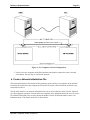
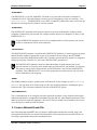
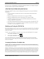
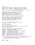
2. A BNC style T-connector must be installed on each AM-319 board. The BNC T-connectors will
be used to link the two computers together as shown in Figure 1. Note how the network is
terminated at each end.
AlphaNET Installation Guide, Revision 05
Building a Simple Network
Page 2-3
Figure 1. Two Computer Network Configuration
3. Now we have two computers with all the hardware and software required to create a network
environment. The next step is to define the network.
4. Create a Network Initialization File
The network initialization file contains all the parameters used to define your computer on the network.
Each time the system boots, the computer processes this file and uses the information to initialize your
network device driver.
The file name used for your network initialization file can be any six-character name you like, followed
by a three-character extension. On each of the two computers in our hypothetical network we will create a
file called ETH100.NIN (since we have chosen the number 100 for our network number, and it is an
Ethernet network). The format of this file is shown below:
AlphaNET Installation Guide, Revision 05
Page 2-4
Chapter Two
DRIVER=AM319
NETWORK=100
GROUP=1
NODE=1
; Each computer must have unique node number
;
within same network and group.
NODECHECK=ON
NODECOUNT=2
GROUPCOUNT=1
NAME=Accounting Network
; DEVICEADDRESS=6
The sections below discuss each of these lines.
DRIVER=
Our network is based on two Eagle 300s, which use a driver called AM319.NDV, so the correct entry for
the DRIVER statement is AM319. (It is not necessary to enter the .NDV extension.)
NETWORK=
The NETWORK parameter can be assigned any number from 1 to 254; the actual number has no
significance. In the example above we used 100. As the network is expanded, any new computers using
Ethernet hardware that are directly connected to our existing network will be assigned the same network
number.
GROUP=
In our sample network initialization file, the GROUP parameter has been assigned the number 1. The
group number, like the network number, is used for identification; the actual number has no real
meaning. Since our network only has two computers, making up one group, we are using the simplest
identificationthe number 1. However, any number from 1 to 254 can be used as a valid group number.
You could easily construct a 20-computer network in the same way we built our two-computer
network. You may want to assign some of these computers different group numbers based on
their location in your facility or based on the departments they support. You may also choose to
assign them the same group number; the choice is yours.
NODE=
Unlike network and group numbers, two computers cannot share the same node number. Each computer
must have its own unique node number. Our network example only has two computers, so the logical
thing to do is to assign one computer node 1 and the other node 2. The NODE parameter will accept any
number from 1 to 65535.
AlphaNET Installation Guide, Revision 05
Building a Simple Network
Page 2-5
NODECHECK=
If NODECHECK is set to ON, AlphaNET will check to see if the node exists before it attempts to
communicate with it. If the node cannot be located, you will immediately get the error message: Node
does not exist. If NODECHECK is set to OFF, if AlphaNET cannot find a node you will still get
the same error message, but it will take a few extra seconds.
NODECOUNT=
The NODECOUNT parameter must always be equal to or greater than the number of physical nodes
(computers) connected to your network. Our example network only has two computers, or nodes, so the
NODECOUNT is 2.
If your NODECOUNT parameter is set to fewer computers than are on the network, you will not
be able to communicate with all of the computers.
GROUPCOUNT=
The GROUPCOUNT parameter is much like the NODECOUNT parameter; it must be equal to or greater
than the number of physical groups that are part of your network. In our example, the NETWORK
parameter was given the identification number 100. Currently, network 100 only contains two computers,
making up one group. Therefore, we will set the GROUPCOUNT parameter to 1.
The GROUPCOUNT parameter needs to contain the number of groups that are part of your
physical network. You do not need to include other groups that access your network via a gateway.
The gateway concept will be discussed later on in this document. Also, like the NODECOUNT
parameter, if the GROUPCOUNT is set to fewer groups than are on the network, you will not be
able to communicate with all groups.
NAME=
The NAME parameter assigns a symbolic name to the network. In our example we used Accounting
Network , but any name can be used as long as it does not exceed 20 characters, including the spaces
between words. This is the name returned on first line of the NTSTAT display.
DEVICEADDRESS=
This is commented out in our example because this particular parameter is only required when using an
Ethernet board that has a configurable board address, like the AM-362. Other Ethernet boards have fixed
addresses and do not require this parameter. The AM-362 Ethernet Paddle Card Installation Instructions
cover this subject in detail for AM-362 boards.
5. Create a Network Ersatz File
One of the things that AlphaNET does is generate a cpuID number based on the network, group, and
node parameters defined in your network initialization file. Each computer on the network will have its
own unique cpuID number that looks something like this:
AlphaNET Installation Guide, Revision 05
Page 2-6
Chapter Two
1677787137You use a cpuID whenever you communicate with another computer on the network. (See the AlphaNET
User’s Guide for examples.) By creating a network ersatz file, you can assign unique, easy to remember
names to represent the cpuID number for each computer on the network, including your own. See
“Defining Ersatz Names for Your Network” in Chapter 3 for more details. Finding out the cpuID for a
particular computer is easy. Just create and run the BASIC program in “Determining Your cpuID
Number” in Chapter 3 or use the NTSTAT/C command and look for the group and node number.
The name of the file containing the network ersatz information can be up to six characters in length,
followed by a .ERZ extension. Since our example network uses Ethernet and we used 100 as a network
number, we’ll create a file (on both computers) called ETH100.ERZ.
Notice in Figure 1 that the two computers each have a name printed above them; DAVE: and HAL:.
Let’s define a network ersatz file that will support these two computers.
The information you enter into the file will look something like this:
DAVE:=1677787137HAL:=1677787138The file is identical for both computers. The name assigned to the cpuID number can be up to six
characters and it must be followed by a colon (:).
6. Create a SYSNAM.DAT File
The SYSNAM.DAT file contains a descriptive phrase describing your computer. This phrase is displayed
when a user connects to your computer as a virtual terminal. It is also displayed when the network status
program NTSTAT is run.
The AlphaNET User’s Guide contains detailed information on NTSTAT and virtual terminal
capabilities.
The SYSNAM.DAT file you create will contain a single line of data limited to 30 characters. Since the
NAME parameter in our hypothetical network was entered as Accounting Network , we’ll assume
the two computers in our network have accounting functions. We’ll give the computer called HAL: a
SYSNAM.DAT file that looks like this:
Accounts Receivable
We’ll make a SYSNAM.DAT file for the computer called DAVE: that looks like this:
Company Payroll
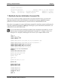
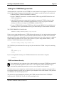
If you run NTSTAT, the resulting display looks something like this:
AlphaNET Installation Guide, Revision 05
Building a Simple Network
Page 2-7
Systems Available:
Accounting Network
(self)
16777871377 DAVE:
1677787138-
Status: Node is on the network
Accounts Receivable
AMOS/32 2.1(353)Company Payroll
AMOS/32 2.2B(416)
7. Modify the System Initialization Command File
So far, we have created everything required to make our network functional. Next, we need to add
supporting statements in the system initialization command file to bring up AlphaNET using the
parameters in our network initialization file, network ersatz file, and SYSNAM.DAT file.
Below there is an example of a system initialization command file with all the required modifications for
supporting AlphaNET highlighted in bold type. Following the system initialization command file is an
explanation for each of the modifications.
If you are not familiar with modifying the AMOS system initialization command file, you must
read the section “Updating the System Initialization Command File” in Chapter 3 before even
editing the fileimproperly modifying this file can leave your computer unable to boot.
:T
JOBS 20
JOBALC JOB1,JOB2
JOBALC NETSER,VTSER
JOBALC MALSER
;
TRMDEF TERM1,AM185=0:9600,AM65,200,200,200,EDITOR=10 VER
;
TRMDEF TERM2,AM185=1:9600,AM65,200,200,200,EDITOR=10 ;
TRMDEF MALSER,PSEUDO,NULL,100,100,100
TRMDEF NETSER,PSEUDO,NULL,100,100,100
TRMDEF VTSER,PSEUDO,NULL,100,100,100
TRMDEF MANAGR,PSEUDO,NULL,100,100,100
;
TRMDEF #5 100,100,100,EDITOR=10
ETHZON 5
TDVDEF AM62A,AM62,AM72,AM75
;
DEVTBL DSK1,DSK2,DSK3,DSK4
;
DEVTBL TRM,RES,MEM
DEVTBL /VCR0
;
QUEUE 200
;
BITMAP DSK,3540,0,1,2,3,4
;
MSGINI 40K
;
ERSATZ ERSATZ.INI
ERSATZ ETH100.ERZ
NETINI ETH100.NIN
;
SYSTEM CMDLIN.SYS
SYSTEM QFLOCK.SYS
SYSTEM SYSMSG.USA
SYSTEM RPC.SYS/N
SYSTEM
SMEM 1M
;
AlphaNET Installation Guide, Revision 05
Page 2-8
Chapter Two
MOUNT DSK1:
MOUNT DSK2:
MOUNT DSK3:
MOUNT DSK4:
;
SETJOB JOB2,TERM2,400K,SETJOB.JIN
;
SETJOB TASK,MANAGR,200K,TSKMGR.JIN
WAIT TASK
;
SETJOB MALSER,MALSER,80K,MALSER.JIN
WAIT MALSER
;
SETJOB NETSER,NETSER,100K,NETSER.JIN
WAIT NETSER
;
SETJOB VTSER,VTSER,32K,VTSER.JIN
;
LOG SYSTEM SERVICE
LOG OPR:
;
SET LINK DAVE:
;
MEMORY 0
The sections below discuss the marked lines briefly, but see Chapter 3 for detailed information.
JOBS 20
You need to increase this number to cover additional users from other computers who will access your
computer at any given time. You can afford to be generous with this number; each additional job only
increases the monitor size by 32 bits. So, we’ve chosen to make the number of jobs 20.
JOBALC NETSER,VTSER
This line allocates a NETSER job, needed for network control, and a VTSER job, used if you want users
from other computers to connect themselves to your computer as virtual terminals.
TRMDEF NETSER,PSEUDO,NULL,100,100,100
This line defines a terminal using the PSEUDO interface driver and the NULL terminal driver. You will
attach this pseudo terminal to the NETSER job later in this section.
TRMDEF VTSER,PSEUDO,NULL,100,100,100
This line defines a terminal using the PSEUDO interface driver and the NULL terminal driver. You will
attach this pseudo terminal to the VTSER job later in this section. (If you do not wish to have other users
connect virtual terminals to your computer, you do not need to set up this job.)
TRMDEF #5 100,100,100,EDITOR=10
This is a special TRMDEF statement used to define Type 2 virtual terminal connections. The syntax for
the TRMDEF command is explained in Chapter 3. That chapter also explains the prerequisites your
computer must meet before using Type 2 connections. See the AlphaNET User’s Guide for more detailed
information on using virtual terminals.
ETHZON 5
The ETHZON statement is used in conjunction with the special TRMDEF statement that defines Type 2
virtual connections. This command creates a special “communication zone” which is part of the interface
between the Ethernet network device driver and the spawned jobs created as part of the virtual terminal
AlphaNET Installation Guide, Revision 05
Building a Simple Network
Page 2-9
connection process. The number specification following the ETHZON statement will always be assigned
the same number as used in the first element of the TRMDEF statement.
TDVDEF AM62A,AM62,AM72,AM75
TDVDEF is only supported on AMOS 2.1 or later releases; it is not supported in AMOS 1.X
releases.
The TDVDEF statement loads the specified terminal drivers for use by virtual terminal connections.
Without the TDVDEF statement, the only terminals supported as virtual terminal connections would be
those defined in the normal TRMDEF statements. The TDVDEF statement can also be used to load all of
the terminal drivers in the DVR: account, for example:
TDVDEF *
MSGINI 40K
AMOS’s Inter Task Communication System, the foundation for all of AlphaNET, requires buffer space
within the system communication area. This space is allocated by the MSGINI command. This command
must be performed before the first SYSTEM command, and takes as an argument the amount of memory
to allocate. A minimum of 16K should be allocated when using AlphaNET.
ERSATZ ETH101.ERZ
The ERSATZ command is followed by the name of the network ersatz file we defined earlier. This
command initializes the network ersatz table and loads it into AMOS. Make sure the network ERSATZ
command is inserted into the initialization command file before the first SYSTEM command.
NETINI ETH101.NIN
The NETINI command is followed by the name of the network initialization file. This command
initializes your network device driver using the information in the network initialization file.
SYSTEM RPC.SYS/N
The remote procedure call facility requires you to allocate and initialize a support module, RPC.SYS,
within system memory. To do so, add the command SYSTEM RPC.SYS/N to the other SYSTEM
commands within the system initialization command file.
SMEM 1M
The SMEM statement sets up a pool of sharable memory for virtual terminal connections. If you use the
SMEM statement, use the /S switch when you initialize VTSER later.
SETJOB NETSER,NETSER,100K,NETSER.JIN
This statement attaches the NETSER job to the NETSER terminal definition, allocates memory for it,
and processes the NETSER job initialization file (NETSER.JIN). The minimum memory allocation for
the NETSER job is 100K.
WAIT NETSER
The WAIT NETSER command that appears directly below the NETSER SETJOB statement insures
NETSER is up and running before going on to the next statement in the system initialization command
file.
AlphaNET Installation Guide, Revision 05
Page 2-10
Chapter Two
SETJOB VTSER,VTSER,32K,VTSER.JIN
Virtual terminal connections afford remote users essentially the same user privileges as local users.
If you choose to support virtual terminal connections, make sure you read the section dealing with
network security in Chapter 3.
This statement attaches the VTSER job, allocates memory for the job, and processes the VTSER job
initialization file (VTSER.JIN). The minimum memory allocation for the VTSER job is 200K unless you
are using SMEM, in which case it is 32K. If you are not using SMEM, you will need to supply the
VTSER job with enough memory to support the maximum number of virtual terminal connections you
would expect to support at any one time. (See Chapter 3 for more details.)
SET LINK DAVE:
The SET LINK command turns on the network and allows your computer to both send and receive data
over the network. You can specify the network ersatz name (as shown in the example) or you can use the
cpuID number. SET LINK can only be executed from the OPR: account. In our example, we included the
SET LINK command in the system initialization command file and you'll notice that just before the SET
LINK command there is a command logging the boot job into OPR: The SET LINK command can also
be entered from AMOS command level after the computer boots. To remove the computer from the
network, use the SET NOLINK command:
SET NOLINK DAVE:
RETURN
8. Create a NETSER.JIN File
In addition to adding the SETJOB statement for the NETSER job in the system initialization command
file, you must create a NETSER.JIN file in your SYS: account. The file will look like this:
:T
LOG SYSTEM SERVICE
NETSER
9. Create a VTSER.JIN File
In addition to adding the SETJOB statement for the VTSER job in the system initialization command
file, you must create a VTSER.JIN file in the account specified in the SETJOB statement. If you do not
specify a logical device and account number, the default is DSK0:[1,4]. The file will look like this:
:T
LOG SYSTEM SERVICE
VTSER/S {password}
The password following the VTSER command is optional and is limited to 10 characters or less. See the
section “VTSER and Network Security” in Chapter 3 for more information on the VTSER password. The
/S switch tells VTSER to use the sharable memory defined by the SMEM statement. See Chapter 3 for
details.
AlphaNET Installation Guide, Revision 05
Building a Simple Network
Page 2-11
TESTING THE NETWORK
In order to test our work, we need to bring up the computers on the network using the modified
TEST.INI file; type:
LOG OPR: RETURN
MONTST AMOS32,TEST.INI
RETURN
or:
LOG OPR: RETURN
MONTST AMOSL,TEST.INI
RETURN
depending on which monitor your computer uses. As each of the computers is booting up on the
modified TEST.INI file, watch the terminal screens and make sure the computers boot without error.
Once each computer has booted and executed the SET LINK command, the network should be fully
functional.
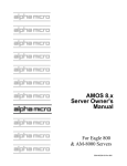
On the HAL: computer, if we enter the command,
NTSTAT/C
RETURN
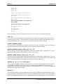
we should see a display that looks similar to this:
Accounting Network
AlphaNET Status
01:54:09 PM
Status: Node is on the network
Node Count:
2
Uptime: 00:00:32
+-----------------------------------------------------------------+
| Block Writes:
11
Block Reads:
11 |
| Network Adds:
5
Network Deletes:
1 |
| Transfers of Control:
45
Protocol Errors:
0 |
| CRC Errors:
2
Framing Errors:
0 |
| Lost Packets:
0
Transmit Errors:
0 |
| Last Node Added: 1677787137Last Node Deleted:
|
+-----------------------------------------------------------------+
Group
1
1
Node
1
2
CPU
16777871381677787137-
Ersatz
(self)
DAVE:
NTSTAT/C Display
The above display shows our network is up and running. NTSTAT indicates that nodes 1 and 2 (DAVE:
and HAL:) are both on the network. Each computer can now share the resources of the other. The next
step is to read Chapter 3 for more detailed information on installing a network, and the AlphaNET User’s
Guide which explains the networking capabilities and commands used in an AlphaNET environment.
AlphaNET Installation Guide, Revision 05
Chapter 3 - Installing the
AlphaNET Software
Installing the AlphaNET software is much the same no matter what physical method of interconnecting
your computers you choose to use. This chapter describes how to install that common body of software
prior to performing any hardware specific installation which is covered in the hardware installation
documentation accompanying your Ethernet interface board for Ethernet installations, or in Chapter 4 for
SerialNET installations.
• Loading the AlphaNET software onto your computer, and installing the Product Installation
Code (PIC).
• Creating the SYSNAM.DAT file.
• Modifying the system initialization command file.
• Testing the new system initialization command file.
• Determining your cpuID number.
OVERVIEW OF THE SOFTWARE INSTALLATION
Before installing the AlphaNET software, check the following items:
• Make sure your operating system meets the minimum revision level requirements as listed in the
software release notes shipped with your AlphaNET software. Attempts to use AlphaNET with
operating system software releases other than those listed in the release notes will yield
unpredictable results.
• Make sure consistent versions of the AlphaNET software are installed on all computers on your
network. Mixing versions of AlphaNET software will not work.
LOADING THE ALPHANET SOFTWARE
AlphaNET, along with other Alpha Micro software products, is distributed on CD-ROM disc. The CDROM disc has a large number of logical devices, with each logical device dedicated to a particular
software product. Each logical device has a label block that describes what software product it contains.
You’ll find a file on the CD-ROM disc called DISC.NDX located on ACD0: in account [1,2]. This file
contains a directory of where each software product is located on the CD-ROM disc. After you have
located AlphaNET, enter the following commands:
LOG OPR: RETURN
COPY=ACDxx:*.*[]
RETURN
xx specifies the logical device containing AlphaNET (e.g., ACD17:).
AlphaNET Installation Guide, Revision 05
Page 3-2
Chapter Three
Once the software has been copied onto your hard disk drive, use the VERIFY command to make sure all
software transferred without error. Type:
VERIFY NET.DIR
RETURN
The VERIFY program will check each file and report any errors.
Installing the Product Installation Code
Under AMOS 2.3 and later, this procedure is not necessary. Beginning with AMOS 2.3, the
AlphaNET software is enabled when you enter the PIC for AMOS. There is no separate AlphaNET
PIC.
After copying the AlphaNET software onto your computer, you must code that software to run on your
specific computer. To do so, execute the NETINI program from AMOS command level. The first time
you do this you will be prompted for a Product Installation Code (PIC). The PIC is a unique identifier for
your system that must be obtained from your dealer.
Enter the following commands:
LOG SYS: RETURN
NETINI RETURN
When asked for the PIC, enter it carefully, verify you have entered it correctly, and press
RETURN .
After a brief pause, you will be returned to AMOS command level and you can proceed with the
remainder of the installation. If you see the error message ?Improper SSD , verify you entered the
correct PIC by re-installing the software and trying again. If you still receive the same error message,
check with your Alpha Micro VAR to make sure the correct PIC was supplied for your system.
You must successfully complete this portion of the AlphaNET installation for any other portion to work.
Reviewing Your PIC
Once you have entered the PIC, if you need to review it, you can see your AlphaNET PIC by typing:
NETINI/P
RETURN
CREATING THE SYSNAM.DAT FILE
Log into DSK0:[1,4] (SYS:), and use AlphaVUE to create a file named SYSNAM.DAT. This file
contains only a single line of dataa name of up to thirty characters describing your computer. This
name is displayed in the status command NTSTAT, and by other commands, and helps other computers
on the network know who you are. For example:
Accounting Computer
AlphaNET Installation Guide, Revision 05
Installing the AlphaNET Software
Page 3-3
If you do not create a SYSNAM.DAT file, NTSTAT will display a blank for your computer description.
The release contains a sample file named SYSNAM.NEW.
UPDATING THE SYSTEM INITIALIZATION FILE
Installing the AlphaNET software consists of adding the following items to your system initialization
command file:
• An increased number of available jobs to allow for virtual terminal connections and remote
procedure calls.
• Setting up a background job to run the network service program, NETSER.
• Setting up a background job to run the virtual terminal service program, VTSER.
• A MSGINI command (specified before the first SYSTEM command) which will allocate
memory for AlphaNET’s message buffers.
• A SYSTEM command which loads and initializes the remote procedure call handler, RPC.SYS.
• Optional setup of Type 2 virtual terminal connections (for Ethernet networks whose computers
use AMOS 2.2 or later and AlphaNET 2.2 or later).
Modifying and Testing the TEST.INI File
Before doing anything else, make a copy of your system initialization command file. We will modify this
copy during the installation to make sure any errors or problems that crop up will not affect your ability
to boot your computer.
To make a copy, log into DSK0:[1,4] and make a copy of your system initialization file. For example:
COPY TEST.INI=AMOSL.INI
RETURN
or:
COPY TEST.INI=AMOS32.INI
RETURN
After creating TEST.INI, edit it with AlphaVUE and make the changes described in the following
sections. Note some of these changes may already have been made, depending on what other software
exists on your computer.
Increasing the Number of Available Jobs
AlphaNET makes use of additional jobs during its execution of both virtual terminal connections and
remote procedure calls (called “spawned jobs”). For this reason, you must increase the maximum number
of jobs supported by your computer.
Within the TEST.INI file, specify the maximum number of jobs using the JOBS statement located at the
beginning of the TEST.INI file. The number following the JOBS command specifies the total number of
jobs that can exist on your computer at any one time. You will need to allocate one entry for each of the
jobs you are predefining, plus one entry for each simultaneous virtual terminal connection you will have
active, plus one entry for each active remote procedure call. Each entry you reserve consumes only 4
AlphaNET Installation Guide, Revision 05
Page 3-4
Chapter Three
bytes of system memory, so it is best to be on the safe side and allocate more JOBS than you think you
actually need.
Adding the NETSER Background Job
AlphaNET requires one job be running the NETSER program in the background to act as a server for
other computers.
1. Add the jobname NETSER to the JOBALC statement.
2. Define a TRMDEF statement for a terminal named NETSER using the PSEUDO interface driver
and NULL terminal driver.
3. Add a SETJOB statement to set up the job, attaching it to terminal NETSER, giving it at least
100K, and having it run the NETSER.JIN initialization file. Add a WAIT NETSER statement
after the SETJOB statement to allow NETSER to finish processing before going on to the next
statement in the system initialization command file.
4. Create a NETSER.JIN file that logs NETSER into DSK0:[1,4] and has it run NETSER.LIT.
The NETSER TRMDEF will look like this:
TRMDEF NETSER,PSEUDO,NULL,100,100,100
NETSER needs memory to do its remote procedure calls and name registration functions. The exact
memory requirements depends on the operations to be performed in your particular installation. There is
no defined minimum or maximum value. We recommend using SETJOB to assign a memory partition of
at least 100K. The SETJOB statement looks like this:
SETJOB NETSER,NETSER,100K,NETSER.JIN
The NETSER.JIN file looks like this:
:T
LOG SYSTEM SERVICE
NETSER
Setting Up Sharable Memory
You can either decide to give the VTSER job enough memory to handle all virtual terminal connections,
or set up a sharable memory area that other applications like AlphaTCP and MULTI can use along with
AlphaNET. To set up a sharable memory area, add the SMEM statement to your system initialization
command file, specifying the amount of memory you want to allocate to be shared. (Include a K for
kilobyte, or M for megabyte.) The SMEM statement goes after the last SYSTEM statement. Example:
SMEM 1M
If you are going to use sharable memory, you need to add the /S switch to the VTSER initialization line.
(See below for details.)
AlphaNET Installation Guide, Revision 05
Installing the AlphaNET Software
Page 3-5
Adding the VTSER Background Job
A background job is required to execute VTSER, the virtual terminal server program. If you do not wish
to have other computers connect virtual terminals to your computer, you do not need to set up this job.
1. Add the jobname VTSER to the JOBALC statement.
2. Define a TRMDEF statement for a terminal named VTSER using the PSEUDO interface and
NULL terminal driver.
3. Add a SETJOB statement to set up the job, attaching it to terminal VTSER, giving it at least
200K and having it run the VTSER.JIN initialization file. (If you are going to use sharable
memory (see above), you can give the VTSER job as little as 32K.)
4. Create a VTSER.JIN file that logs VTSER into a disk account (DSK0:[1,4] is the default), and
optionally specifies a password that must be given when making a virtual terminal connection.
The VTSER TRMDEF will look like this:
TRMDEF VTSER,PSEUDO,NULL,100,100,100
Unless you are using sharable memory, VTSER allocates the memory for its virtual terminal connections
out of its own partition. In this case, you must allocate sufficient memory to VTSER for its own needs
plus the needs of as many simultaneous virtual terminal connections as you wish to support. A minimum
of 200K should be allocated, with 512K or more preferred. If you are using sharable memory, 32K is
sufficient. The SETJOB statement will look like this:
SETJOB VTSER,VTSER,32K,VTSER.JIN
The VTSER.JIN job initialization file must log the job in and initialize VTSER. It may look something
like this:
:T
LOG DSK0:[1,4]
VTSER
If you are using sharable memory, the VTSER initialization line must contain a /S option:
VTSER/S
VTSER and Network Security
Users connected to your computer via the virtual terminal server program VTSER have essentially
the same operational capabilities as direct users. Your computer operator should take steps to
insure that only authorized persons have access to your computer over the network.
To restrict access to your computer by virtual terminals, you can specify a computer access password to
be requested each time someone tries to connect to your computer with a virtual terminal. This password
is in addition to the normal login password.
The password is entered immediately following the VTSER command located in the VTSER job
initialization file VTSER.JIN. The file will look something like this:
AlphaNET Installation Guide, Revision 05
Page 3-6
Chapter Three
:T
LOG DSK0:[1,4]
VTSER/S MAGICWORD
The password, which appears in bold type in the example, can be up to 10 characters long; VTSER does
not distinguish between upper and lower case letters. To protect your VTSER password, the file
containing the password should be located on a logical disk device which can’t be accessed over the
network. The system initialization command file with the above VTSER job should also contain the
command SET NOACCESS DSK0:. If you do not prevent access to DSK0: anyone could read your
VTSER password over the network and then make a virtual terminal connection to your computer. You
may also choose to locate your VTSER.JIN file on some logical disk device other than DSK0:. For
example:
SETJOB VTSER,VTSER,32K,DSK11:VTSER.JIN[200,1]
For best protection from unauthorized virtual terminal connections, make sure you use SET
NOACCESS to prevent access to the logical device that contains the VTSER.JIN file.
If you are using AMOS 2.2 (or later) software releases with extended disk format, you can create
or modify files with user privileges that prevent them from being read over the network. See your
AMOS documentation for information on creating files with user privileges.
TDVDEF (AMOS 2.1 and Later Only)
The TDVDEF statement (valid only with AMOS 2.1 or later releases) must be inserted into your system
initialization command file after the last TRMDEF statement and before the first NETINI command to
load the specified terminal drivers for use by virtual terminal connections. Without the TDVDEF
statement, the only terminals supported as virtual terminal connections would be those defined in the
normal TRMDEF statements on the local node.
Using the TDVDEF statement, you can load any or all of your terminal driver files into memory when
your computer boots. You can follow the TDVDEF statement with the wild card symbol (*) and all the
TDV files in the local node’s DSK0:[1,6] will be loaded into memory, or you can follow the TDVDEF
statement with specific TDV names:
TDVDEF *
or:
TDVDEF AM65.TDV, AM72.TDV, AM62A.TDV
Allocating Message Buffers with MSGINI
AMOS’s Inter Task Communication System, the foundation for all of AlphaNET, requires buffer space
within the system communication area. This space is allocated by the MSGINI command. This command
must be performed before the first SYSTEM command, and takes as an argument the amount of memory
to allocated. A minimum of 16K should be allocated when using AlphaNET.
AlphaNET Installation Guide, Revision 05
Installing the AlphaNET Software
Page 3-7
Initializing the Remote Procedure Call System
The remote procedure call facility requires you allocate and initialize a support module, RPC.SYS,
within system memory. To do so, add the command SYSTEM RPC.SYS/N to the other SYSTEM
commands within the system initialization command file.
Defining a Network
For each network your computer connects to, you must define the network using the NETINI command.
The NETINI command must appear in your system initialization command file after the MSGINI
command, but prior to any SYSTEM commands. For example:
NETINI ETH101.NIN
The NETINI command takes as an argument the name of a network initialization command file. This
network initialization file defines to the computer the unique settings and parameters of a network. The
exact contents of this file will therefore differ from one type of network to another. However, much of the
content is the same regardless of network type and is explained below.
Here’s the format of a network initialization command file:
DRIVER = xxxxxx
NETWORK = x
GROUP = x
NODE = x
NODECHECK = xxx
NODECOUNT = xx
GROUPCOUNT = xx
NAME = Network Descriptive Name
To create a network initialization file, specify the network driver name for your specific network type in
the DRIVER statement. (For information on what Ethernet driver to use, consult the hardware installation
instructions accompanying the Ethernet network interface card you installed. For SerialNET, use the
SERIAL driver.) Then specify the network, group, and node numbers identifying your computer as a
node on a specific network. The network number can be from 1 to 254. Each line of the system
initialization command file can be up to 512 characters in length.
The NODECHECK statement tells AMOS whether or not to check for the existence of a node before
trying to communicate with it. If NODECHECK is set to ON, you will get an immediate error message
(Node does not exist ) if the node you are trying to communicate with is not found. If
NODECHECK is set to OFF, or if the NODECHECK statement is not included in your network
initialization file, if the node is not found you will still get the error message, but it will take several
seconds longer.
The value defined in the NODECOUNT statement must be equal to, or greater than, the number of nodes
on your network. If you do not include a NODECOUNT statement in your network initialization file, the
NODECOUNT number defaults to 10. This is not a problem if you have 10 or less nodes defined on your
network, but if you have more than 10 nodes defined, you will not be able to communicate with all your
nodes and you will assorted network problems.
AlphaNET Installation Guide, Revision 05
Page 3-8
Chapter Three
The value defined in the GROUPCOUNT statement must be equal to, or greater than, the number of
groups defined on your network. If you do not include a GROUPCOUNT statement in your network
initialization file, the GROUPCOUNT number defaults to 1. This is not a problem if you only have one
group defined on your network, but if you have more than one group defined, you will not be able to
communicate with all the groups defined on your network.
The NAME statement specifies a symbolic name for each network you define; the NAME statement must
not exceed 20 characters.
Using the specific data about your node and network, use AlphaVUE to create a network initialization
file.
Defining Ersatz Names for Your Network
Dealing directly with AlphaNET internet addresses in the form of cpuIDs can be very cumbersome.
While these eight- to eleven-digit numbers serve to uniquely identify each node on all networks, they are
certainly not intuitively obvious.
Ersatz devices provide a simple way to define a symbolic equivalent to the cpuID numbers. Anyone
wishing to refer to a specific node on the network can then use the symbolic name, rather than the
numeric identifier.
Ersatz devices are defined by the ERSATZ command in the system initialization command file. The
ERSATZ command reads in a text file defining the ersatz device names and their equivalent cpuIDs and
stores them for later use. This text file need only be created once, and then copied to all nodes on the
network.
We recommend you create a separate ersatz device definition file for each network on your computer.
For example, if the network you are installing is Ethernet network 1, create the ersatz device definition
file ETH001.ERZ. The contents of this file, created with AlphaVUE, might look something like:
MAIN: = 16842753PRINT: = 16842754WRHSE: = 16842755PAYROL: = 16842757ACCT2: = WRHSE:DSK2:[100,4]
You can use names up to six characters in length (plus the colon). The ersatz definition can contain other
ersatz names, and can specify any part of a complete file specification.
The ERSATZ command may be used multiple times within the system initialization command file to
process multiple ersatz device specification files. All of the ERSATZ commands, however, must be
grouped together, with no intervening commands, before the first SYSTEM command. For example:
ERSATZ ETH101.ERZ
ERSATZ ETH102.ERZ
ERSATZ SER003.ERZ
AlphaNET Installation Guide, Revision 05
Installing the AlphaNET Software
Page 3-9
Turning on the Network
The SET LINK command turns on the network and allows your computer to both send and receive data
over the network. You can use SET LINK from within the system initialization command file or at
AMOS command level, but log into OPR: first in either case. You can specify a node ersatz name or you
can use your cpuID number. For example, if your node is named DAVE:, near the end of your system
initialization command file (after all the network jobs have been set up and processed), enter:
LOG OPR:
SET LINK DAVE:
To turn off access to the network for node DAVE:, use:
SET NO LINK DAVE:
A Sample Initialization File
A sample system initialization command file is shown below. This example is intended to give you a
better understanding of how to set up each of the previously discussed commands. Of course, the details,
such as number and type of devices, non-AlphaNET jobs, etc., will differ with your own computer. The
portions shown in bold below are the AlphaNET-related sections.
:T
JOBS 20
JOBALC JOB1,JOB2
JOBALC NETSER,VTSER
JOBALC MALSER
;
TRMDEF TERM1,AM185=0:9600,AM65,200,200,200,EDITOR=10 VER
;
TRMDEF TERM2,AM185=1:9600,AM65,200,200,200,EDITOR=10 ;
TRMDEF MALSER,PSEUDO,NULL,100,100,100
TRMDEF NETSER,PSEUDO,NULL,100,100,100
TRMDEF VTSER,PSEUDO,NULL,100,100,100
TRMDEF MANAGR,PSEUDO,NULL,100,100,100
;
TRMDEF #5 100,100,100,EDITOR=10
ETHZON 5
TDVDEF AM62A,AM62,AM72,AM75
;
DEVTBL DSK1,DSK2,DSK3,DSK4
;
DEVTBL TRM,RES,MEM
DEVTBL /VCR0
;
QUEUE 200
;
BITMAP DSK,3540,0,1,2,3,4
;
MSGINI 40K
;
ERSATZ ERSATZ.INI
ERSATZ ETH100.ERZ
NETINI ETH100.NIN
;
SYSTEM CMDLIN.SYS
SYSTEM QFLOCK.SYS
SYSTEM SYSMSG.USA
SYSTEM RPC.SYS/N
AlphaNET Installation Guide, Revision 05
Page 3-10
Chapter Three
SYSTEM
SMEM 1M
;
MOUNT DSK1:
MOUNT DSK2:
MOUNT DSK3:
MOUNT DSK4:
;
SETJOB JOB2,TERM2,400K,SETJOB.JIN
;
SETJOB TASK,MANAGR,200K,TSKMGR.JIN
WAIT TASK
;
SETJOB MALSER,MALSER,80K,MALSER.JIN
WAIT MALSER
;
SETJOB NETSER,NETSER,100K,NETSER.JIN
WAIT NETSER
;
SETJOB VTSER,VTSER,32K,VTSER.JIN
;
LOG SYSTEM SERVICE
LOG OPR:
;
SET LINK DAVE:
;
MEMORY 0
The job initialization file NETSER.JIN should contain the following:
:T
LOG DSK0:[1,4]
NETSER
The job initialization file VTSER.JIN should contain the following:
:T
LOG DSK0:[1,4]
VTSER/S {password}
If your computer uses user names, you will need to add the appropriate user names and passwords (if
needed) to the job initialization files (for example, LOG SYSTEM SERVICE).
ETHERNET TYPE 2 VIRTUAL TERMINAL CONNECTIONS
If you are running AlphaNET 2.2 or later, using an AMOS 2.2 (or later) operating system, and using
Ethernet as your network data transport device, you can use Type 2 connections with the CONECT
program. Type 2 connections provide an improvement in virtual terminal performance, 8-bit character
support, and use of the command line editor.
To use these new features under CONECT, you will need to add a special TRMDEF statement. You
must also create a special communication “zone,” which requires one additional statement in your system
initialization command file. This setup is discussed below.
If you are using a serial network, or if you not using AlphaNET 2.2 and AMOS 2.2, the following
sections are not applicable to your configuration.
AlphaNET Installation Guide, Revision 05
Installing the AlphaNET Software
Page 3-11
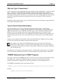
Why Use Type 2 Connections?
Type 2 connections provide substantially higher performance than the standard Type 1 connections. With
Type 1 connections, all communication between the connecting terminal and the host computer go
through a single job, VTSER. This makes VTSER a bottleneck when multiple connections are in effect,
slowing down communication. With Type 2 connections, most of the communication takes place directly
between the connecting terminal and its spawned job on the host, freeing up VTSER for improved
performance.
In addition to improved performance, Type 2 connections also provide 8-bit character support and the use
of the AMOS command line editor.
Type 2 Virtual Terminal Restrictions
The most important point to keep in mind when defining the enhanced Type 2 virtual terminal
connections is that they are “real jobs” that count against the licensed number of jobs allocated in your
AMOS operating system. Every TRMDEF statement in your system initialization command file that
defines the use of a physical port represents a real job. Make sure the number of enhanced virtual
terminal connections you define in the special TRMDEF and ETHZON statements (when added to your
existing real jobs) does not cause you to exceed the number of licensed jobs in your AMOS operating
system.
If there are more enhanced virtual terminal connections defined than your AMOS port license supports,
no TCBs will be allocated for enhanced virtual terminal connections.
The number of jobs defined in the JOBS statement at the top of your system initialization
command file must be equal to, or greater than, the total number of jobs you wish to support at
any given time. This includes all real jobs, which includes enhanced virtual terminal connections,
plus all PSEUDO jobs.
If you define five (for example) as the number of Type 2 virtual terminal connections for your computer,
any virtual terminal connections beyond five will use the standard, non-enhanced Type 1 connections.
TRMDEF Statement (Type 2 CONECT Support)
The purpose of this special TRMDEF statement is to allocate a pool of Terminal Control Blocks (TCBs)
to be used by jobs “spawned” by VTSER in response to a remote connection request issued by
CONECT. Note that this is applicable only when using Ethernet as a network transport device.
The TRMDEF command line syntax for allocating TCBs is:
TRMDEF #count Inwidth,Inbuffer,Outbuffer,Editor=#-of-recall-buffers
Example:
TRMDEF #10 100,100,100,EDITOR=10
AlphaNET Installation Guide, Revision 05
Page 3-12
Chapter Three
This is similar to the traditional TRMDEF statement. The #10 causes 10 TCBs with associated terminal
buffers to be made available for use by remote job connections.
You can have only one TRMDEF #count statement in your initialization file. If you have more than one,
all of them after the first are ignored.
For best results, the special TRMDEF statement described above should be the last TRMDEF
statement in your system initialization command file.
In AMOS 2.3 and later, each TCB you allocate in this way counts as a user toward your AMOS license.
Therefore, the total number of real terminals defined in your initialization file plus the number of TCBs
defined by TRMDEF #count must be equal to or less than your AMOS user license. If you try to allocate
more TCBs than you have jobs available, you see an error message and only the number of TCBs you
have available under your AMOS license are allocated.
Creating Communication Zone (Type 2 CONECT Support)
In order to support remote connections requested by CONECT, the host computer must have a special
communication “zone” defined in the initialization command file. This zone is part of the interface
between the Ethernet network driver and the spawned jobs created as the result of a CONECT connection
request. To set up this area, an ETHZON statement must be added to the system initialization command
file. The syntax is simply:
ETHZON maxjobs
maxjobs is the maximum number of CONECT connections to be supported at any given time. The
maxjobs number should match the number listed in the special TRMDEF statement described above.
Example:
ETHZON 10
This statement, when added to your system initialization command file, would allocate an Ethernet
communication zone large enough to support a maximum of 10 virtual terminal connections created by a
CONECT request. Make sure you insert the ETHZON statement after the TRMDEF statements and
before the first NETINI command.
TESTING THE NEW INITIALIZATION COMMAND FILE
After making the changes described above, log into DSK0:[1,2] and test your new initialization
command file using the MONTST command. For AMOS/L systems, enter:
MONTST AMOSL.MON,TEST.INI
RETURN
For AMOS/32 systems, enter:
MONTST AMOS32.MON,TEST.INI
RETURN
If the computer doesn’t reboot properly, press your computer’s RESET button to reboot under your
original initialization file. Re-check TEST.INI for mistakes and try again.
AlphaNET Installation Guide, Revision 05
Installing the AlphaNET Software
Page 3-13
Once the computer has booted correctly, use SYSTAT to make sure the job running NETSER is in an
MS state, and the job running VTSER is in an SL state. If not, recheck your TEST.INI file to make sure
these jobs were properly initialized. If you are unsuccessful after several tries, you may wish to attach
either one of these background jobs to a real terminal during the boot process so you may see any error
messages they may be reporting.
When you have successfully completed the TEST.INI file and used MONTST to test it, rename it to
replace your previous initialization command file. On an AMOS/L computer, enter:
COPY AMOSL.OLD=AMOSL.INI RETURN
RENAME/D AMOSL.INI=TEST.INI RETURN
On an AMOS/32 computer, enter:
COPY AMOS32.OLD=AMOS32.INI RETURN
RENAME/D AMOS32.INI=TEST.INI RETURN
You can now install the physical network connection and its related software. This installation is
described in the following sections.
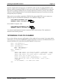
DETERMINING YOUR CPU ID NUMBER
If you wish to find out what your cpuID number will be (which will save you time if you want to define
ersatz names), you can use the AlphaBASIC program listed below. It asks you for information from your
network initialization file, and returns the cpuID AlphaNET will give you.
MAP1
MAP1
MAP2
CPU'SOURCE,B,4
CPU'NUM,@CPU'SOURCE
NET'NODE,B,2
MAP2 NET'GROUP,B,1
MAP2 NET'NUM,B,1
MAP1 ANSWER,S,1
START:
INPUT LINE "Enter your Network number: ";NET'NUM : PRINT
INPUT LINE "Enter your Group number: ";NET'GROUP : PRINT
INPUT LINE "Enter your Node number: ";NET'NODE : PRINT
PRINT "Your CPU ID number is: ";
PRINT CPU'SOURCE USING "##########";"-" : PRINT
INPUT "Would you like to find another CPUID (Y/N)?
";ANSWER
IF UCS(ANSWER) = "Y" THEN GOTO START
END
AlphaNET Installation Guide, Revision 05
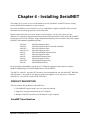
Chapter 4 - Installing SerialNET
This chapter gives you an overview of the hardware used by SerialNET. SerialNET uses the existing
serial terminal interface hardware on your computer.
Due to the availability of serial interfaces on every Alpha Micro computer, SerialNET makes an ideal
interconnection for setting up gateways between networks.
Because Alpha Micro has used a wide variety of serial interfaces over the years, there are some
differences in capabilities and performance between these different interfaces when used with SerialNET.
In particular, not all of the interfaces support hardware handshaking. Those interfaces which fully support
SerialNET with hardware handshaking include:
AM-1006
AM-1003
AM-1203
AM-130/134
AM-355
AM-135
AM-145
AM-185
AM-355B
AM-140
AM-1000 Expansion Ports
AM-1000 Expansion Ports (Non-Z80 controlled)
AM-1200 Expansion Ports
AM-1400 Expansion Ports
AM-1500/AM-2000 Expansion Ports
AM-1600 Expansion Ports
AM-2000M Expansion Ports
AM-3000 Expansion Ports
AM-3000M Expansion Ports
AM-3000M Serial Ports
By using hardware handshaking, speeds up to 57.6 Kbaud is supported. Other interfaces without
hardware handshaking are not recommended for use with SerialNET.
The AM-310, AM-1013, and AM-1213 boards are not recommended for use with SerialNET. While the
AM-350 board is very useful for speeding up computer throughput, it is not the place to connect the
SerialNET touse an AM-355 port off the CPU board.
PRODUCT DESCRIPTION
The basic features and capabilities of SerialNET are:
• Full AlphaNET support using a low-cost, point-to-point link.
• Support for communication speeds up to 57.6 Kbaud.
• Multiple SerialNET connections can be made to a single computer.
SerialNET Specifications
AlphaNET Installation Guide, Revision 05
Page 4-2
Chapter Four
Network type:
Topology:
Maximum Segment Length:
Max. Nodes/Net:
Medium:
Bit Rate:
Termination:
Packet Size:
Point-to-point asynchronous connection
Point-to-point
50 ft. (RS-232), 1000 ft. (RS-422)
2
Shielded cable recommended
Up to 57,600 BPS
Not needed
12 to 4096 bytes per packet
BUILDING CABLES FOR SERIALNET
The cables used by SerialNET are constructed in the same manner as normal terminal cables, including
shielding and length considerations. The connections that must be made are:
RS-232 connection (DB-25 or DB-9):
2
7
3
4
5
3
7
2
5
4
RS-422 connection (DB-9):
2
8
3
6
4
5
7
3
6
2
8
5
4
7
OVERVIEW OF THE SOFTWARE INSTALLATION
You must do the following to install the SerialNET software:
1. Make sure you have successfully installed the AlphaNET software, as described in Chapter 3 of
this book.
2. After copying the software onto the computer, run the NETINI program and enter the Product
Installation Code (PIC).
3. Create a unique network initialization file, SERnnn.NIN, to install your computer onto the
network with a unique group and node designation. The network initialization file is also
described in Chapter 3.
4. Modify your System Initialization Command file to define the serial interface connection you
wish to use, and to execute the necessary programs to bring up the SerialNET system.
AlphaNET Installation Guide, Revision 05
Installing SerialNET
Page 4-3
DO NOT modify your system initialization command file directly, but create a test copy,
TEST.INI, and modify that. Once this copy is executing properly, you may replace your original
system initialization command file with the test copy.
CREATING A NETWORK INITIALIZATION FILE FOR SERIALNET
The following is an example of the file (SERnnn.NIN) that will install your computer on the network.
For more details on the network initialization file, see Chapter 3.
The sample below shows a typical network initialization file for SerialNET. Note you must specify the
SERIAL driver, and must turn NODECHECK off.
DRIVER = SERIAL
NETWORK = 3
GROUP = 1
NODE = 1
NODECHECK = OFF
NAME = Serial Network
;
;
;
;
;
;
;
Network driver
Network number
Group number
Node number (unique
within a group and network)
Checks node # before request
Descriptive name
DEFINING THE SERIALNET TERMINAL CONNECTION
SerialNET uses a standard terminal port as its physical connection. This terminal port must be defined to
AMOS through the use of the TRMDEF statement in the system initialization command file, the same as
for any other terminal.
The only unique thing about defining a terminal as a SerialNET connection is the naming of the terminal.
So the SerialNET software can locate the connection you wish to use, it requires the terminal be named
using the form SERnnn, where nnn is the network number associated with the terminal connection.
Thus, to define a terminal port for use with network 3, you would define a terminal named SER003,
using a command similar to the following:
TRMDEF SER003,AM355=16:38400,TELTYP,100,100,100,,NULL
Note SerialNET requires the NULL modem driver be specified at the end of the TRMDEF command. It
also requires that no line editor be installed on the port. The terminal driver is ignored by SerialNET, but
should be specified as TELTYP to reduce overhead.
SETTING UP ERSATZ NAMES
You will probably want to set up ersatz device names for the nodes on your SerialNET, as described in
Chapter 3. By using ersatz device names, you can avoid the use of lengthy and cumbersome network
address numbers.
AlphaNET Installation Guide, Revision 05
Page 4-4
Chapter Four
CHECKING OUT THE INSTALLATION
Once you have made all of the changes to system initialization command file and the network
initialization command file, you are ready to start testing. See Chapter 3 for information on testing the
system initialization command file.
AlphaNET Installation Guide, Revision 05
Chapter 5 - Installing Network
Gateways
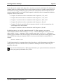
Gateways allow you to gain access to networks your computer is not physically connected to. This is
done by routing all traffic for that network to a network node which does have a physical connection.
This extra routing is transparent to both you and the software in use. You must, however, pre-define all
networks to which you wish to connect, and establish routing paths for each.
DEFINING GATEWAYS
You define a gateway much as you would any other network, using the NETINI program, except instead
of defining a physical connection by specifying a network driver, you specify a logical connection by
specifying the network node to forward messages to. (Instead of specifying a .NIN file to the NETINI
program, to set up a gateway, you specify a .GIN gateway file.)
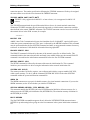
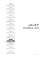
The elements required to connect different networks through a common gateway are illustrated on the
next two pages. In the figure below, four networks are shown. Networks #1, #2, and #3 are serial
networks. A serial network is a point-to-point type network. This means each point to point connection
makes up a unique network. In the illustration you can see Network #1 connects Computer A to
Computer E; Network #2 connects Computer B to Computer E; Network #3 connects Computer C to
Computer E.
Network# 4 is an Ethernet network that allows a large number of computers to share a common network.
Computer D, Computer E, and Computer F are able to communicate with each other, because they are all
part of a common network (Network #4).
AlphaNET Installation Guide, Revision 05
Page 5-2
Chapter Five
Four Networks
AlphaNET Installation Guide, Revision 05
Installing Network Gateways
Page 5-3
Look at the network example in the figure above; note there are network initialization files defining each
computer (node) on all four networks. However, the elements necessary for creating a gateway between
the networks are missing. Without the gateway defined, the communication between computers in our
network example would be very limited. Each computer would only be able to communicate with other
computers within its local network:
• Computer A would not be able to communicate with Computers B, C, D, and F.
• Computer B would not be able to communicate with Computers A, C, D, and F.
• Computer C would not be able to communicate with Computers A, B, D, and F.
• Computer D would not be able to communicate with Computers A, B, and C.
• Computer E is directly attached to all the computers, therefore it is able to communicate with
each computer on all four networks.
• Computer F would not be able to communicate with Computers A, B, and C.
By defining gateways, we can fully connect this network. To define a gateway, you create an
initialization file (filename.GIN) containing a NETWORK= statement defining the network you wish to
make available, a NAME= statement to assign a symbolic name, and a FORWARDTO= statement to
define the network address of the node to which to forward all traffic for the network being defined. Then
enter a NETINI statement processing that .GIN file in your system initialization command file. For
example:
NETINI SER001.GIN
To fully interconnect all six computers shown in the figure above, each of the computers would have to
define gateways as shown in the table below (in addition to defining the networks to which they are
physically connected):
The network initialization files (*.NIN) must be defined in your system initialization command file
before your gateway initialization files (*.GIN).
AlphaNET Installation Guide, Revision 05
Page 5-4
Chapter Five
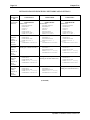
INITIALIZATION FILES DEFINING NETWORKS AND GATEWAYS
Function of
Initialization
File
Computer’s
own network
definition.
Gateway
definition
linking
computer to
Ethernet
Network 4.
Gateway
definition
linking
computer to
Serial
Network 1.
Gateway
definition
linking
computer to
Serial
Network 2
Gateway
definition
linking
computer to
Serial
Network 3.
COMPUTER A
COMPUTER B
COMPUTER C
Serial Network 1
cpuID 16842754SER001.NIN
DRIVER=SERIAL
NETWORK=1
GROUP=1
NODE=2
NODECOUNT=2
NODECHECK=OFF
NAME=SerialNET 1
ETH004.GIN
NETWORK=4
NODECHECK=OFF
NAME=Ethernet 4
Serial Network 2
cpuID 33619970SER002.NIN
DRIVER=SERIAL
NETWORK=2
GROUP=1
NODE=2
NODECOUNT=2
NODECHECK=OFF
NAME=SerialNET 2
ETH004.GIN
NETWORK=4
NODECHECK=OFF
NAME=Ethernet 4
Serial Network 3
cpuID 50397186SER003.NIN
DRIVER=SERIAL
NETWORK=3
GROUP=1
NODE=2
NODECOUNT=2
NODECHECK=OFF
NAME=SerialNET 3
ETH004.GIN
NETWORK=4
NODECHECK=OFF
NAME=Ethernet 4
Gateway
Gateway
Gateway
FORWARDTO=16842753-
FORWARDTO=33619969-
FORWARDTO=50397185-
Not applicable (Computer A is
already part of Serial Network 1.)
SER001.GIN
NETWORK=1
NODECHECK=OFF
NAME=Serial 1 Gateway
FORWARDTO=33619969-
SER001.GIN
NETWORK=1
NODECHECK=OFF
NAME=Serial 1 Gateway
FORWARDTO=50397185-
SER002.GIN
NETWORK=2
NODECHECK=OFF
NAME=Serial 2 Gateway
FORWARDTO=16842753-
Not applicable (Computer B is
already part of Serial Network 2.)
SER002.GIN
NETWORK=2
NODECHECK=OFF
NAME=Serial 2 Gateway
FORWARDTO=50397185-
SER003.GIN
NETWORK=3
NODECHECK=OFF
NAME=Serial 3 Gateway
FORWARDTO=16842753-
SER003.GIN
NETWORK=3
NODECHECK=OFF
NAME=Serial 3 Gateway
FORWARDTO=33619969-
Not applicable (Computer C is
already part of Serial Network 3.)
(Continued)
AlphaNET Installation Guide, Revision 05
Installing Network Gateways
Page 5-5
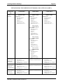
INITIALIZATION FILES DEFINING NETWORKS AND GATEWAYS (PART 2)
Function of
Initialization
File
Computer’s own
network
definition.
COMPUTER D
Ethernet Network 4
cpuID 67174401ETH004.NIN
DRIVER=ETHER
NETWORK=4
GROUP=1
NODE=1
NODECOUNT=3
NODECHECK=OFF
NAME=Ethernet 4
COMPUTER E
Ethernet Network 4
cpuID 67174402ETH004.NIN
DRIVER=ETHER
NETWORK=4
GROUP=1
NODE=2
NODECOUNT=3
NODECHECK=OFF
NAME=Ethernet 4
COMPUTER F
Ethernet Network 4
cpuID 67174403ETH004.NIN
DRIVER=ETHER
NETWORK=4
GROUP=1
NODE=3
NODECOUNT=3
NODECHECK=OFF
NAME=Ethernet 4
Serial Network 1
cpuID 16842753SER001.NIN:
DRIVER=SERIAL
NETWORK=1
GROUP=1
NODE=1
NODECOUNT=2
NODECHECK=OFF
NAME=SerialNET 1
Serial Network 2
cpuID 33619969SER002.NIN:
DRIVER=SERIAL
NETWORK=2
GROUP=1
NODE=1
NODECOUNT=2
NODECHECK=OFF
NAME=SerialNET 2
Gateway
definition linking
computer to
Serial Network 1.
Gateway
definition linking
computer to
Serial Network 2
Gateway
definition linking
computer to
Serial Network 3.
SER0001.GIN
NETWORK=1
NODECHECK=OFF
NAME=Serial 1 Gateway
FORWARDTO=67174402SER002.GIN
NETWORK=2
NODECHECK=OFF
NAME=Serial 2 Gateway
FORWARDTO=67174402SER003.GIN
NETWORK=3
NODECHECK=OFF
NAME=Serial 3 Gateway
FORWARDTO=67174402-
AlphaNET Installation Guide, Revision 05
Serial Network 3
cpuID 50397185SER003NIN:
DRIVER=SERIAL
NETWORK=3
GROUP=1
NODE=1
NODECOUNT=2
NODECHECK=OFF
NAME=SerialNET 3
Not applicable (Computer D is
already part of Serial Network
1.)
Not applicable (Computer D is
already part of Serial Network
2.)
Not applicable (Computer D is
already part of Serial Network 3)
SER001.GIN
NETWORK=1
NODECHECK=OFF
NAME=Serial 1 Gateway
FORWARDTO=67174402SER002.GIN
NETWORK=2
NODECHECK=OFF
NAME=Serial 2 Gateway
FORWARDTO=67174402SER003.GIN
NETWORK=3
NODECHECK=OFF
NAME=Serial 3 Gateway
FORWARDTO=67174402-
Page 5-6
Chapter Five
When actually defining a FORWARDTO address, you may use an ersatz name in place of the
cpuID number (that’s the big decimal number). See Chapter 3 of this document for more
information on the use of ersatz names.
AlphaNET Installation Guide, Revision 05
Index
.
G
.GIN file · 5-1
.NIN file · 3-7
Gateway · 5-1
FORWARDTO · 5-3
initialization file (.GIN) · 5-3
installation · 5-1
GROUPCOUNT · 3-8
default · 3-8
1
10BaseT cabling · 2-2
I
A
AMOS user license · 3-12
B
Installation overview · 3-1
Inter Task Communication system · See ITC
ITC · 3-6
J
BNC T connectors · 2-2
C
CD-ROM disc · 3-1
Computer name · 3-2
CONECT · 3-11
CpuID · 3-13
finding out · 3-13
E
Ersatz name · 3-8, 4-3
Ethernet · 2-2
cabling · 2-2
communication zone · 3-12
hardware · 2-2
ETHZON · 3-12
F
Finding cpuID · 3-13
FORWARDTO · 5-3
AlphaNET Installation Guide, Revision 05
Jobs
increasing number of · 3-3
JOBS statement · 3-3
M
Message buffers · See ITC
MONTST · 3-13
MSGINI · See ITC
N
NAME statement · 3-8
NETINI · 3-2, 3-7, 5-1, 5-3
NETSER · 3-3, 3-4
memory · 3-4
NETSER.JIN · 3-4
Network
driver · 3-7
initialization · 3-7
Network Service · See NETSER
NODECHECK · 3-7
NODECOUNT · 3-7
default · 3-7
NTSTAT · 2-12
Page ii
O
Operating system compatibility · 3-1
Index
Spawned jobs · 3-3, 3-12
SYSNAM.DAT · 3-2
System initialization command file · 3-3
sample · 3-9
testing · 3-3, 3-13
P
Password · 3-6
PIC · 3-2
review · 3-2
Product Installation Code · See PIC
Protecting devices · 3-6
R
Remote procedure call handler · See RPC.SYS
RPC.SYS · 3-3, 3-7
S
SerialNET · 4-1
cables, building · 4-2
features · 4-1
hardware · 4-1
initialization file, SERnnn.INI · 4-3
installation · 4-1
specifications · 4-2
SERnnn.INI · 4-3
SET LINK · 3-9
SET NO LINK · 3-9
SMEM · 3-4
Software installation · 3-1
verifying · 3-2
T
TCBs · 3-12
TDVDEF · 3-6
Terminal drivers · See TDVDEF
Testing system initialization command file · 3-13
Thicknet cabling · 2-2
Thinnet cabling · 2-2
Turning network on/off · 3-9
Type 2 connections · 2-9, 3-11
restrictions · 3-11
V
VERIFY · 3-2
Virtual terminal
8-bit character support · 3-11
line editor support · 3-11
Type 1 connections · 3-11
Type 2 connections · 3-11
Virtual terminal access
device protection · 3-6
password · 3-5
VTSER · 3-5
background job · 3-5
job initialization file, VTSER.JIN · 3-6
memory · 3-5
password · 3-5
AlphaNET Installation Guide, Revision 05