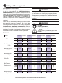
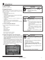
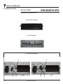
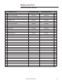
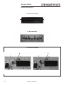
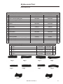
1
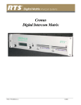
Installation
Instructions
Installation and service of this
appliance should be performed by
qualified personnel. CFM suggests
NFI certified or factory-trained
professionals, or technicians
supervised by an
NFI certified professional.
Models:MO18SPN, MO18SPL, MO24SPN,
MO24SPL,MO18RRN, MO18RRL,MO24RRN, MO24RRL
CFM Burner/Hearth and Log Kits
Intended for use in all CFM Corporation factory built fireplaces
Check with your local building code agency before you begin installation to ensure compliance with local codes, including
the need for permits and follow-up inspections. If you encounter any problems regarding code approvals, or if you need
clarification of any of the instructions contained here, contact the Technical Services Dept.,
CAUTION
DO NOT DISCARD THIS MANUAL
• Important operating • Read, understand • Leave this manual with
and follow these
party responsible for
and maintenance
instructions for safe
use and operation.
instructions included.
installation and
operation.
WARNING
WARNING
If the information in these instructions is not followed exactly, a
fire may result causing property
damage, personal injury, or death.
• Do not store or use gasoline or other flammable vapors and liquids in the vicinity of
this or any other appliance.
• What to do if you smell gas:
- Do not try to light any appliance.
- Do not touch any electrical switch. Do not
use any phone in your building.
- Immediately call your gas supplier from
a neighbor’s phone. Follow the gas
supplier’s instructions.
- If you cannot reach your gas supplier, call
the fire department.
• Installation and service must be performed
by a qualified installer, service agency, or
the gas supplier.
HOT! DO NOT TOUCH.
SEVERE BURNS MAY RESULT.
CLOTHING IGNITION MAY RESULT.
Glass and other surfaces are hot during
operation and cool down.
• Keep children away.
• CAREFULLY SUPERVISE children in same room as
appliance.
• Alert children and adults to hazards of high
temperatures.
• Keep clothing, furniture, draperies and other
combustibles away.
In the Commonwealth of Massachusetts:
• This appliance must be installed by a licensed plumber
or gas fitter.
• The chimney flue damper, when used with gas logs, will
be welded open or completely removed.
• A CO detector shall be installed in the room where the
appliance is installed.
20013055 7/05 Rev. 0
Read this manual before installing or operating this appliance.
Please retain this owner’s manual for future reference.
Congratulations
Congratulations on selecting a CFM gas log set—an elegant
and clean alternative to burning wood. The CFM gas log set
you have selected is designed to provide the utmost in safety, reliability, and efficiency.
As the owner of this new gas log set, you’ll want to read
and carefully follow all of the instructions contained in this
owner’s manual. Pay special attention to all cautions and
warnings.
This owner’s manual should be retained for future reference.
We suggest you keep it with your other important documents
and product manuals.
The information contained in this owner’s manual, unless
noted otherwise, applies to all models and gas control systems.
Your new gas log set will give you years of durable use and
trouble-free enjoyment. Welcome to the CFM family of appliance products!
Listing Label Information/Location
The model information regarding your specific gas log
set can be found on the rating plate.
20013055 7/05 Rev. 0
Table of Contents
1 Listing and Code Approvals
A. Appliance Certification. . . . . . . . . . . . . . . . . . . . . . . . . 4
B. Table 1. . . . . . . . . . . . . . . . . . . . . . . . . . . . . . . . . . . . . 4
2 Getting Started
A.
B.
C.
D.
E.
Size of Firebox. . . . . . . . . . . . . . . . . . . . . . . . . . . . . . . 5
Negative Pressure. . . . . . . . . . . . . . . . . . . . . . . . . . . . 5
Tools and Supplies Needed. . . . . . . . . . . . . . . . . . . . . 5
Inspect the Appliance and Components . . . . . . . . . . . 5
Components of the Gas Hearth Kit . . . . . . . . . . . . . . . 6
3 Appliance Preparation
A. Gas Supply Connection. . . . . . . . . . . . . . . . . . . . . . . . 6
B. Convert to Left Side Gas Piping. . . . . . . . . . . . . . . . . . 6
C. Gas Pressure. . . . . . . . . . . . . . . . . . . . . . . . . . . . . . . . 7
4 Installation Instructions
A.
B.
C.
D.
E.
F.
G.
H.
Install the Damper Stop. . . . . . . . . . . . . . . . . . . . . . . . 9
Install the Burner/Pan Assembly . . . . . . . . . . . . . . . . 10
Switch or Remote Installation . . . . . . . . . . . . . . . . . . 10
Install the Grate. . . . . . . . . . . . . . . . . . . . . . . . . . . . . 10
Place Sand/Vermiculite, Rockwool . . . . . . . . . . . . . . 10
Install the Logs. . . . . . . . . . . . . . . . . . . . . . . . . . . . . . 11
Adjust the Pilot Flame . . . . . . . . . . . . . . . . . . . . . . . . 11
Inspect the Venting System. . . . . . . . . . . . . . . . . . . . 12
5 Operating Instructions
A. Lighting Instructions. . . . . . . . . . . . . . . . . . . . . . . . . . 13
B. Glass Doors. . . . . . . . . . . . . . . . . . . . . . . . . . . . . . . . 15
C. Important Safeguards . . . . . . . . . . . . . . . . . . . . . . . . 15
6 Maintaining and Servicing the Appliance
A.
B.
C.
D.
Servicing Your Appliance. . . . . . . . . . . . . . . . . . . . . . 16
Cleaning Your Appliance . . . . . . . . . . . . . . . . . . . . . . 16
Annual Inspection . . . . . . . . . . . . . . . . . . . . . . . . . . . 16
Troubleshooting. . . . . . . . . . . . . . . . . . . . . . . . . . . . . 17
7 Reference Materials
A. Replacement Parts . . . . . . . . . . . . . . . . . . . . . . . . . . 18
B. Optional Components . . . . . . . . . . . . . . . . . . . . . . . . 22
C. Warranty . . . . . . . . . . . . . . . . . . . . . . . . . . . . . . . . . . 23
20013055 7/05 Rev. 0
1
Listing and Code Approvals
A.Appliance Certification
The Burner/Hearth and Log Kits have been tested and listed
in the U.S. in accordance with ANSI Z21.60b-2004 and
ANSI Z21.84-2003 (Gas Log Set). In Canada the Gas Log
Hearth Kits have been tested and approved in accordance
with CGA 2.26b-2004. They have been listed by OMNI Test
Labs for installation and operation in the United States and
Canada as described in these Installation and Operating
Instructions. All components are UL, OMNI, or CSA safety
certified.
Check with your local building code agency prior to installing
this appliance to ensure compliance with local codes,
including the need for permits and follow-up inspections.
In the absence of local codes, comply with the National
Fuel Gas Code, ANSI Z223.1-Latest Edition in the U.S.;
in Canada, the CAN/CGA B149 Installation Codes. If any
assistance is required during installation, please contact your
local dealer or call the Technical Services Department .
WARNING
Improper installation, adjustment, alteration, service
or maintenance can cause injury or property damage.
Refer to the owner’s information manual provided with
this appliance. For assistance or additional information
consult a qualified installer, service agency or the gas
supplier.
WARNING
Fire Risk
Exhaust Fumes Risk
• Do NOT use this appliance as a “vent-free
heater.
The flue must be permanently open. Refer
to Table 1.
B.Table 1
Product
Inlet BTU
MO18SPN MO18SPL MO24SPN MO24SPL MO18RRN MO18RRL MO24RRN MO24RRL
Nat.
LP
67,000
Manifold Pressure IN.
WC/Kpa
Nat.
LP
3.5/.018
Max. Inlet Pressure
IN. WC/Kpa
Nat.
LP
10/.052
Min. Inlet Pressure IN.
WC/Kpa.
Nat.
LP
3.5/.018
Orifice Size
Nat.
LP
#26
Front
Rear
Depth
Height
33
20
15
21
33
20
15
21
38
26
15
21
38
26
15
21
33
20
15
21
33
20
15
21
38
26
15
21
38
26
15
21
39/251.6
39/251.6
48/309.7
48/309.7
39/251.6
39/251.6
48/309.7
48/309.7
Min. Fireplace
Opening Size (In.)
Min. Vent Opening in
Square In./cm
68,000
47,000
67,000
58,000
3.5/.020
11.0/0.058
47,000
3.5/.022
11.0/0.060
10/.054
13/.069
10/.058
3.5/.022
#26
11.0/0.062
#26
#42
20013055 7/05 Rev. 0
13/.075
3.5/.024
11.0/0.064
#26
#47
These Hearth/Log Kits are for use with all CFM Factory built fireplaces.
11.0/0.064
13/.073
11.0/0.060
#47
3.5/.024
10/.056
3.5/.020
58,000
11.0/0.062
13/.071
11.0/0.058
68,000
#42
2
Getting Started
A.Size of Firebox
CAUTION
See Table 1 in Section 1.B.
Sharp Edges
• Wear protective gloves
and safety glasses during
installation.
B.Negative Pressure
Negative pressure results from the imbalance of air available for the fireplace to operate properly. Causes for this
imbalance include:
• Exhaust fans (kitchen, bath, etc.).
• Range hoods.
• Combustion air requirements for furnaces, water heaters
and other combustion appliances.
• Clothes dryers.
• Location of return-air vents to furnace or air
conditioning.
• Imbalances of the HVAC air handling system.
• Upper level air leaks: recessed lighting, attic hatch
opening, duct leaks.
WARNING
Asphyxiation Risk
This appliance produces carbon monoxide
(CO).
• The free opening areas (in square inches)
of the chimney damper as shown in the
tables must be met.
• User must make sure damper is locked
open.
• The installer is responsible to ensure
proper ventilation of flue gases before
appliance is used.
Fire needs to draft properly for safe
operation.
C.Tools and Supplies Needed
Tools and supplies normally required for installation:
Pliers
Phillips screwdriver
Tape measure
Crescent wrenches
Gas shutoff valve
Non-corrosive leak check solution
3/4 in. wrench, 7/16 in. wrench
D.Inspect the Appliance and Components
• Remove the contents from the carton. Attached to the
burner are tags identifying the manufacturer name, serial
number, model number (including gas log size), BTU
ratings, gas type, etc.
• Review the attached tags before proceeding. Ensure
that all minimum fireplace dimension requirements are
achieved using Table 1 in Section 1.B. See Figure 2.1.
Ensure the gas type provided in the fireplace coincide
with the gas type marked on the tag.
Depth dimension
Rear dimension
WARNING
CFM disclaims any responsibility for, and
the warranty will be voided by, the following
actions:
• Installation and use of any damaged appliance or
vent system component.
• Modification of the appliance or vent system.
• Installation other than as instructed by CFM•
Improper positioning of the gas logs or the glass
door.
• Installation and/or use of any component part not
approved by CFM
Any such action may cause a fire hazard.
Front dimension
Figure 2.1
Measure Firebox
20013055 7/05 Rev. 0
WARNING
WARNING
Inspect appliance and components for
damage. Damaged parts may impair safe
operation.
Keep appliance dry.
• Mold or rust may cause
odors.
• Water may damage controls.
• Do NOT install damaged components.
• Do NOT install incomplete components.
• Do NOT install substitute components.
Report damaged parts to dealer.
WARNING
E.Components of the Gas Hearth Kit
The Burner/Hearth Kit consists of the following:
•
•
•
•
•
•
•
•
•
•
Burner/Pan Assembly
Grate Assembly
Glowing Embers
Sand (NG only)
Vermiculite (LP only)
Lava Rock
Damper Stop
Extended Handle
Log Set
Remote ready Kit, switch included or remote control sold
separately
Do NOT use this appliance if any part has been under
water. Immediately call a qualified service technician
to inspect the appliance and to replace any part of the
control system and any gas control which has been
under water.
20013055 7/05 Rev. 0
WARNING
Shock Risk
Fire Risk
Use ONLY optional accessories approved
for this appliance.
• Using non-listed accessories voids
warranty.
• Using non-listed accessories may result
in a safety hazard.
• Only CFM approved accessories may be
used safely.
3
Appliance Preparation
Note: Have the gas supply line installed in accordance
with local building codes, if any. If not, follow ANSI 223.1.
Installation should be done by a qualified installer approved
and/or licensed as required by the locality. (In the Commonwealth of Massachusetts installation must be performed by
a licensed plumber or gas fitter.)
WARNING
Fire Risk
Explosion Risk
Verify inlet pressures.
• H i g h p r e s s u r e m a y c a u s e o v e r f i r e
condition.
• Low pressure may cause explosion.
Install regulator upstream of valve if line
pressure is greater than 1/2 psig.
A.Gas Supply Connection
Ensure fittings are of the appropriate size and type on the
gas line connection. If the tubing has to be cut to length be
sure to use the proper cutting and flaring tool. Also, be careful not to crimp the tubing while bending. If the tubing becomes crimped, do not use for installation.
WARNING
Gas Leak Risk
• Support control when attaching pipe to
prevent bending gas line.
Certified joint compound ot Teflon tape must be used on all
threaded male connections to ensure a tight seal.
WARNING
Fire Risk
Explosion Risk
Personal Injury Risk
An explosion could occur if a connection is
made directly to an unregulated propane (LP)
tank.
B.Convert to Right Side Gas Piping
•
•
•
•
•
Remove black cap from right side.
Remove two pilot head screws.
Remove two pilot bracket screws.
Detach thermocouple and pilot from control valve.
Remove the control valve from the left side of the burner
pan and replace on right, upside down.
Note: Prior to installing the valve, use Teflon tape or joint
compound on the male threads.
•
•
•
•
Reinstall pilot bracket on right side of burner.
Reinstall pilot assembly to pilot bracket.
Reattach pilot tube and thermocouple to control valve.
Reinstall black cap removed from right side of burner to
left side.
• Install valve shield.
Note: An individual manual shutoff valve (not supplied) is
required when installing this appliance. Check local codes
for location of shut off valve.
Note: A listed (and Commonwealth of Massachusetts
approved) 1/2 in. (13 mm) T-handle manual shut-off valve
and flexible gas connector are connected to the 1/2 in.
(13 mm) control valve inlet.
• If substituting for these components, please consult
local codes for compliance.
20013055 7/05 Rev. 0
WARNING
Fire Risk
Explosion Risk
• Gas build-up during line purge may
ignite.
• Purge should be performed by qualified
technician.
• Ensure adequate ventilation.
• Ensure there are no ignition sources such
as sparks or open flames.
C.Gas Pressure
Proper input pressures are required for optimum appliance
performance. Gas line sizing requirements need to be made
following NFPA54 and CSA B-149..
WARNING
Fire Risk
Explosion Risk
High pressure will damage valve.
• Disconnect gas supply piping BEFORE
pressure testing gas line at test pressures
above 1/2 psig.
• Close the manual shutoff valve BEFORE
pressure testing gas line at test pressures
equal to or less than 1/2 psig.
WARNING
CHECK FOR GAS LEAKS
Fire Risk
Explosion Risk
Asphyxiation Risk
• Check all fittings and connections.
• Do not use open flame.
• After the gas line installation is complete,
all connections must be tightened and
checked for leaks with a commercially
available, non-corrosive leak check
solution. Be sure to rinse off all leak check
solution following testing.
Fittings and connections may have loosened
during shipping and handling.
WARNING
Fire Risk
Explosion Risk
Do NOT change the valve settings.
• This valve has been preset at the
factory.
• Changing valve settings may result in fire
hazard or bodily injury.
WARNING
Shock Risk
Explosion Risk
Do NOT wire 110V to valve.
• Gas Supply Pressure: Minimum inlet gas supply pressure
must be 3.5 in. W.C. for natural gas or 11 in. W.C. for LP
gas for the purpose of input adjustment. Maximum inlet
gas pressure must not exceed 7.0 in. W.C. for natural
gas or 13 in. W.C. for LP gas. The gas line supplying the
appliance must be sufficient size to furnish the appropriate
supply pressure to the appliance while operating in the
“High” setting. (Minimum line ID of 1/2 in. required if the
line is longer than 20 ft.
• Gas Line Pressure Test: Perform pressure test according
to state and local code (if pressure exceeds 1/2 in. psi [3.5
kPa]) before appliance is connected. Be sure to release
air pressure from the gas line before connection is made
to the appliance. Excessive pressure will damage the gas
control and may cause a gas leak.
• Gas Leak Test: Make sure the gas connections are tight.
Turn on the gas and coat each joint with a non-corrosive
gas leak check solution. Always check for gas leaks with a
mild soap and water solution applied with a brush no larger
than 1” (25mm). Never apply soap and water solution with
a spray bottle. Air bubbles will form indicating any leaks.
DO NOT USE A FLAME OR ANY TYPE OF IGNITION
SOURCE TO CHECK FOR LEAKS. All leaks must be
corrected before proceeding with installation.
• The appliance must only be installed in a solid-fuel burning
fireplace with the flue damper clamped open.
• The minimum permanent free opening (in square inches)
that must be provided by the fireplace chimney or damper
to vent the flue gases is provided in Table 1. If the free
opening is smaller than the specified area, do not use this
appliance.
• The damper must be removed or fixed in a manner in
which will secure it open. Some jurisdictions require the
damper to be removed or permanently welded fully open.
Check with state and local codes.
• Be sure that the chimney is completely unobstructed to
ensure proper ventilation of flue gases including carbon
monoxide (CO). CO (a poisonous gas) is tasteless,
odorless, colorless and undetectable without proper
equipment.
High Altitude Derate
In the USA, input BTU shall be derated 4% (one orifice size)
per 1000 feet for altitudes above 2000 feet. In Canada, input
BTU shall be derated 10% (two orifice sizes) at altitudes
from 2000-4500 feet.
CAUTION
• Prevent accidental appliance operation when not
attended.
• Unplug or remove batteries from remote control if
absent or if appliance will not be used for an extended
period of time.
• P r o p e r t y d a m a g e p o s s i b l e f r o m e l e v a t e d
temperatures.
20013055 7/05 Rev. 0
4
Installation Instructions
For Use With All Other Fireplaces
A. Damper Stop:
For Use with BR, BC, SR, SC, TF and TL Series CFM
Corporation Fireplaces
This Damper Stop is designed to work on all CFM Corporation BR, BC, SR, TF and TL series fireplaces. For all other
fireplaces, refer to note bellow.
When installing a decorative gas appliance in a fireplace,
some local codes require this Damper Stop to be used so
the Damper will not close completely. To install the Damper
Stop:
The Damper Locking Bracket is already installed on all BR,
BC, SR, TF and TL fireplaces. Locate the Damper Locking
Bracket on the left side of the fireplace’s Combustion Dome.
(Fig. 1)
With the Damper open, align the two slots on either side
of the cut-out on the Damper Stop with the two small holes
on the angled portion of the Damper Locking Bracket. Attach the Damper Stop with the Screws provided, as shown
in Figure 2.
NOTE: Some of the early fireplace units may not have the
holes in the end of the Damper Locking Bracket. If this is
the case, use the Damper Stop as a template to drill two
(2) 1/8” holes in the Damper Locking Bracket to mount the
Damper Stop.
The Damper Clamp provided keeps your damper from accidentally closing during operation of your set. This Damper Clamp must be installed onto your Damper at all times.
NOTE: The damper clamp is designed to hold the damper
plate open 3 inches. However, the damper must be fully
open when the log set is in operation.
Install the Damper Clamp onto the edge of the damper plate.
Attach by securing the bolt provided to the damper plate with
an adjustable wrench. (Fig. 3)
If the Damper Clamp does not fit, drill a ¼” hole onto the
damper plate and install an anchor bolt with a nut, at a 90 degree angle, so that the damper plate will remain fully open.
The proper finished installation of the Damper Clamp is
shown in Figure 4. If the bolt fails to block the damper in
an open position, the damper should be removed from the
chimney.
To check your vent for proper drafting: Light a tightly rolled
newspaper on one end and place it at the inside front edge
of the fireplace. Observe the smoke and be sure the vent
is properly drawing it up the chimney. If the smoke is drawn
back into the room, extinguish the flame and remove any obstruction until proper venting is achieved. If that fails, check
with a qualified chimney sweep.
DamperPlate
Damper Locking Bracket
DamperPlate
Damper Clamp
Figure 1
Damper Locking Bracket
Figure 3
Damper Stop
Figure 4
Figure 2
20013055 7/05 Rev. 0
E.Place Sand/Vermiculite, Rockwool
B.Install the Burner/Pan Assembly
The burner/pan assembly is shipped ready for left-hand gas
connection. See Section 3.B. for right-hand connection.
• Remove the existing cap or gas jet assembly from the
gas stub in your fireplace. Clean the threads using a wire
brush or steel wool. Apply Teflon tape or joint compound
to the steel fitting and attach the provided brass adapter
to the stub.
• Place the burner/pan assembly in the fireplace. The pan
should be centered both front to back and side to side.
• Bend the provided gas connector to facilitate its installation
between the burner and the gas stub.
• Attach one end of the gas connector to the brass elbow
or safety pilot fitting. Attach the other end to the brass
adapter at the gas tube.
• Pour the sand (NG models) or vermiculite (LP models)
into the burner pan. Sand or vermiculite should follow the
slope of pan, covering it and the burner tube completely.
Important: Cover the pilot assembly to protect it before
installing the sand or vermiculite.
Note: Use caution so vermiculite does not get into the air
mixer on LP models.
• Allow the sand or vermiculite to spill out the front of the
pan and over the sides onto the fireplace floor.
WARNING
C.Switch or Remote Installation
Explosion Risk
• Follow rockwool placement instructions
in this manual.
• Replace rockwool material annually.
Improperly placed rockwool interferes with
proper burner operation.
• Remote - follow instructions included with it.
• Switch:
- Plug in two wires from the switch to wires on valve.
D.Install the Burner Pan and Grate
• The burner pan should be centered under the existing
grate, side to side. The center leg of the grate should be
positioned in front of the burner tube so as to ensure proper
placement and proper flame position. Refer to Figure 4.2.
Note: For easy placement, tilt grate up and hold burner
pan at 45 degree angle starting with back left corner of
burner pan.
• Lightly place dime-sized pieces of rockwool evenly on top
of the sand or vermiculite.
• Inspect the pilot burner to ensure it is clear of any
rock wool.
Note: For best results, do not pack down the rock wool.
The placement of rock wool can have an effect on flame
pattern and may need to be adjusted to achieve a desired
appearance.
• The gas burns at the point of the least resistance. In case
of an uneven flame pattern it may be necessary to adjust
the materials in the pans (using an object such as a long
screwdriver) to achieve the desired effect.
Figure 4.2
10
Center Burner Pan Under Grate
20013055 7/05 Rev. 0
G.Adjust the Pilot Flame
F. Install the Logs
WARNING
Fire Risk
Explosion Risk
Personal Injury Risk
Failure to position the parts in accordance
with the diagrams provided with the log
packages or failure to use only parts
approved with this appliance may result in
property damage or personal injury.
• Install the logs using the installation instructions included
with them.
• Light the burner as outlined in the operating section. Allow
the flame pattern to stabilize. If you are satisfied with the
flame pattern go to the next step. If you want more or less
flame around the front log, turn off the gas and move the
grate backward or forward.
• Once you are satisfied, turn on the gas and go on to the
next step.
• Arrange the top logs as shown in your log set up
instructions. Light the burner as outlined in the operating
instructions and allow the flame to stabilize.
• Spread the lava rock around the outside of the burner
pan on the floor of the fireplace. If possible, cover the gas
connector with the cinders. DO NOT cover any part of the
pilot assembly.
MO18
Step 1
Step 2
Step 3
The pilot flame should be a soft blue color and should surround the last 1/2 in. of the thermocouple tip. The pilot adjustment screw is located on pilot valve beside control knob.
Refer to Figure 4.3. If pilot flame must be adjusted, use a
standard slotted screwdriver to turn screw clockwise to reduce flame or counterclockwise to increase flame.
Figure 4.3
Pilot Adjustment Screw
MO24
Step 1
Step 2
Step 3
20013055 7/05 Rev. 0
11
H.Inspect the Venting System
The fireplace venting system is designed and constructed to
develop a positive flow adequate to remove flue gases to the
outside atmosphere. See fireplace installation instructions.
A spillage test must be made before the installed
appliance is left with the consumer
• Close all doors and windows in the home.
• Light the log set.
• After three minutes, test with a smoke match, smoke
candle, stick incense or cigarette one inch below the top of
the opening (lintel) moving across the full width. If spillage
(smoke drawn into the room) occurs, it will most likely be
near the top, outside corners.
Possible Cures if Spilling Occurs
• The damper should be fully open.
• The fireplace opening needs to be reduced by adding a
drop panel across the top under the lintel.
• The air supply from outdoors needs to be increased. Open
the outside air kit if the appliance is so equipped, or crack
open a door or window.
• If necessary, seek expert advice. Do not operate this
appliance.
Cleaning
WARNING
Fire Risk
Explosion Risk
Inspect external vent cap regularly.
• Ensure no debris blocks cap.
• Combustible materials blocking cap may
ignite.
• Restricted air flow affects burner
operation.
12
20013055 7/05 Rev. 0
5
Operating Instructions
A.Lighting Instructions
20013055 7/05 Rev. 0
13
14
20013055 7/05 Rev. 0
B.Glass Doors
If your fireplace is equipped with glass doors:
• Glass doors should be in fully open position when
appliance is operating.
• Operating in the closed position will block the radiant
heat output and may cause incomplete combustion of
the gas and will cause the gas valve to overheat and be
damaged.
WARNING
Fire Risk
Explosion Risk
Do not close the glass doors during appliance
operation.
• Could cause incomplete combustion of
the gas.
• Glass doors may be closed when the hearth kit is not being
used.
C.Important Safeguards
• Other Fuels
- Although your gas log set is very realistic in appearance,
it is not a real woodburning fire and must not be used
for burning any fuel other than natural or propane
gas.
- To avoid irreparable damage to the appliance and/or
personal injury, wood, matches, paper, garbage or any
other material must not be placed or thrown on top of
the logs.
• Appliance Safety
- To avoid personal injury, do not touch hot surfaces
when the appliance is operating.
- Always ensure that the fireplace screen is closed when
the appliance is operating.
- Close supervision is necessary when the appliance is
being used near children.
• Do not remove any of the attached metal plates, which
contain important safety and operating information.
• Keep the appliance area clear and free of all combustible
materials, gasoline and other flammable vapors and
liquids.
• A qualified service technician must perform installation
and repair. The appliance should be inspected and cleaned
annually by a qualified service technician. More frequent
cleaning may be required due to excessive lint, dust, pet
hair, etc. It is imperative that the control compartments,
burners and air passageways are unobstructed during
operation.
- Review proper placement of logs, rockwool, lava rock,
sand or vermiculite.
- Check the wiring.
- Ensure there are no gas leaks.
- Ensure the flow of combustion and ventilation air is not
obstructed (front grilles and vent caps).
• Before installing into a solid fuel burning fireplace, the
chimney and firebox should be inspected and cleaned to
remove soot, creosote, ashes, paint, bird nests etc.
• Annual examination of the chimney must be performed
by a qualified agency to ensure proper ventilation of flue
gases created by this appliance.
• Have the chimney and adjacent structure inspected and
cleaned by qualified professionals. CFM recommends
that NFI certified professionals, or technicians under the
direction of certified professionals, conduct a minimum of
an NFPA 211 Level 2 inspection of the chimney.
• Replace component parts of the chimney and fireplace as
specified by the professionals.
• Ensure all joints are properly engaged and the chimmney
is properly secured.
• Do not allow fans to blow directly into the fireplace. Avoid
any drafts that alter burner flame pattern.
• Do not use a blower insert, heat exchanger insert or other
accessories not approved for use with this appliance.
Solid fuels shall not be burned in a fireplace where a
decorative appliance is installed.
• If glass doors are present, the glass doors must be fully
opened while appliance is in operation.
WARNING
Do NOT use this appliance if any part has been under
water. Immediately call a qualified service technician
to inspect the appliance and to replace any part of the
control system and any gas control which has been
under water.
20013055 7/05 Rev. 0
WARNING
Fire Risk
High Temperatures
Keep combustible household items away
from appliance.
Do NOT obstruct combustion and ventilation
air.
• Do NOT place combustible items on top
of or in front of appliance.
• Keep furniture, draperies away from
appliance.
15
6
Maintaining and Servicing the Appliance
A.Servicing Your Appliance
C.Annual Inspection
WARNING
WARNING
Risk of injury or property damage
Before servicing:
• Turn off gas.
• Turn off electricity to appliance.
• Disable remote control, if one is present.
• Ensure appliance is completely cooled.
After Servicing:
• Replace any screen or barrier that was removed.
• Reseal and reinstall any venting removed for
servicing.
• Repair and replacement work should be done by a
qualified service technician.
• Always shut off the gas supply and make sure the appliance
is cool before beginning any service operation.
• Always check for gas leaks after servicing.
• Always check for proper venting.
B.Cleaning Your Appliance
Your gas logs require little care. Keep the burner assembly,
logs and burner area surrounding the logs clean by
vacuuming or brushing with a dry paint brush at least twice
a year.
• The logs become fragile after burning. Take care in
handling.
• Always turn off the gas to the pilot before cleaning. For
relighting, refer to lighting instructions located Section 5
of these instructions.
• Always keep the appliance clear and free from combustible
materials, gasoline, and other flammable vapors and
liquids.
• Never obstruct the flow of combustion and ventilation air.
Keep the front of the appliance clear of all obstacles and
materials.
• Leave clearance of at least 36 in. from the front of the
fireplace.
• The air shutter should not be blocked.
CAUTION
• Logs can get very hot. Handle only when they are
cool.
16
20013055 7/05 Rev. 0
Annual inspection by qualified technician
recommended.
Check:
• Condition of doors, surrounds and fronts.
• Obstructions of combustion and ventilation
air.
• Condition of logs.
• Condition of firebox.
• Gas connections and fittings.
• Obstructions of termination cap.
Clean:
• Glass.
• Logs.
• Burner, burner ports.
Risk of:
• Fire
• Delayed ignition or explosion
• Exposure to combustion fumes
• Odors
D.Troubleshooting
With proper installation and maintenance, your new decorative gas appliance should provide years of trouble-free service.
If you do experience a problem, refer to the troubleshooting guide below. This guide will assist you or a qualified service
technician in the diagnosis of problems and the corrective action to be taken.
Symptoms
1. A match will not light the
pilot.
Possible Causes
A. Main gas shutoff valve is
closed
Corrective Action
1. Make sure that the shutoff valve located on the
incoming gas line is open.
B. There is air in the gas line. 1. Light a match. Turn the valve knob to the “PILOT”
position and depress. Keep the match near the pilot
burner until it lights.
C. The valve knob is in the
“OFF” position.
1. Turn the valve knob to the “PILOT” position and
depress. Keep the match near the pilot burner until it
lights.
D. The pilot orifice is plugged, 1. This repair requires tools and some degree of
not allowing gas to flow.
experience. Call a qualified service technician.
E. There is no gas supply to
the fireplace.
1. Check the plumbing to ensure the fireplace has been
hooked up the gas supply line.
2. The propane tank is empty.
2. The pilot lights, but
will not stay lit after
carefully following lighting
instructions.
A. The thermocouple is too
tight or too loose.
1. The thermocouple must be attached to the valve
finger-tight plus a 1/8 turn with a wrench.
B. There is a weak pilot
flame.
1. The pilot flame must engulf the thermocouple.
Clean and/or adjust the pilot for maximum flame
impingement on the thermocouple.
C. Defective thermocouple
1. Check the thermocouple with a millivolt meter as
follows: Disconnect the thermocouple from the valve
and connect the red lead of the meter to the silver end
of the thermocouple. Connect the black lead of the
meter to the copper tubing of the thermocouple. Light
the pilot and keep the knob depressed while taking
readings. The meter readings should be greater than
14 mV. If not, replace the thermocouple.
3. The pilot is on, but there is A. A blockage is preventing
no gas to the main burner;
gas flow.
the valve knob is on.
B. Defective valve.
1. Inspect the burner orifice for obstruction. Call a
qualified service technician.
1. Replace the gas valve. Call a qualified service
technician.
20013055 7/05 Rev. 0
17
7
Reference Materials
A.Replacement Parts
CFM Hearth Kits
Service Parts
Exploded Parts Diagram Natural Gas
1 - Burner Pan Assembly
2 - Grate Assembly
3 - Hearth Kit Assemblies
6
14
5
6
1
14
4
1
3
12
18
5
11
13
12
20013055 7/05 Rev. 0
11
13
Replacement Parts
Exploded parts diagram - Natural Gas
#
Description of Part
MO18SPN,MO18RRN
MO24SPN,MO24RRN
Qty.
Damper Stop Assembly
4304045
4304045
1
1
Burner Pan Assembly
20013012
20013013
1
3
Valve - Remote Ready (RR)
20013014
20013014
1
4
Valve- Standing Pilot (SP)
20013015
20013015
1
5
Pilot Assy - NG
20013016
20013016
1
6
Orifice
20013017
20013018
1
11
Valve Knob Extension
3304198
3304198
1
12
Valve Knob
3304213
3304216
1
13
Connector Tube
20013023
20013023
1
14
Valve Shield
20013024
20013024
1
Sand
4310006
4310006
1
Lava Rock
4310010
4310010
1
Glowing Embers
4310001
4310001
1
Damper Stop for BR/BC, SR/SC, TF/TL only
3030176
3030176
1
Damper Stop Screws
7521901
7521901
2
20013055 7/05 Rev. 0
19
CFM Hearth Kits
Service Parts
Exploded Parts Diagram LP
1 - Burner Pan Assembly
2 - Grate Assembly
3 - Hearth Kit Assemblies
6
5
6
5
19
19
1
14
1
14
4
12
20
3
13
11
12
20013055 7/05 Rev. 0
13
11
Replacement Parts
Service Parts List LP
#
Description of Part
MO18SPL,MO18RRL
MO24SPL,MO24RRL
Qty.
Damper Stop Assembly
4304045
4304045
1
1
Burner Pan Assembly
20013012
20013013
1
3
Valve - Remote Ready (RR)
20013032
20013032
1
4
Valve- Standing Pilot (SP)
20013033
20013033
1
5
Pilot Assy - LP
20013034
20013034
1
6
Orifice
20013035
20013036
1
11
Valve Knob Extension
3304198
3304198
1
12
Valve Knob
3304213
3304216
1
13
Connector Tube
20013023
20013023
1
19
Regulator
20013042
20013042
1
14
Valve Shield
20013024
20013024
1
Vermiculite
4310008
4310008
1
Lava Rock
4310010
4310010
1
Glowing Embers
4310001
4310001
1
Damper Stop for BR/BC, SR/SC, TF/TL only
3030176
3030176
1
Damper Stop Screws
7521901
7521901
2
Description of Log Parts
MO18M
MO24M
Qty.
Log 1
20013043
20013048
1
Log 2
20013044
20013049
1
Log 3
20013045
20013050
1
Log 4
20013046
20013051
1
Log 5
20013047
20013052
1
Log 1
Log 2
Log 3
Log 4
Log 5
Log 1
Log 2
Log 3
Log 4
Log 5
20013055 7/05 Rev. 0
21
B.Optional Components
Safety Pilot Burner/Hearth Kits
20013010
Hearth ember burner for 18 in. hearth kits
20013011
Hearth ember burner for 24 in. hearth kits
Remote Ready Burner/Hearth Kits
22
20013019
Hearth ember burner for 18 in. hearth kits
20013020
Hearth ember burner for 24 in. hearth kits
20013021
on/off remote control
20013021
Wall switch (on/off only)
20013025
Switch in Log
20013055 7/05 Rev. 0
C.Owner Registration/Warranty
Please complete and return your owner registration card to ensure proper warranty coverage. If you wish to communicate
with the factory, write to
LIMITED ONE YEAR WARRANTY
For CFM Corporation Decorative Gas Appliances
CFM Corporation extends the warranties specified in paragraphs A and B below with respect to its Vermont Castings
Decorative Appliances (the “Gas Appliance”), including CFM
Corporation supplied accessories and components referred
to in those paragraphs, subject to the following conditions and
limitations:
(1) These warranteis extended only the the Gas Appliance installed in the continental United States, including Alaska, and
Canada; only if and so long as the accordance with the installation and operating instructions furnished therewith; and only
if and so long as Gas Appliance is not removed from its original
installation.
(2) These warranties are limited to only the component parts
manufactured and supplied by CFM Corporation. The use of
components manufactured by others with the Gas Appliance
(except for a listed Type B venting system and defined in the installation instructions) could create serious safety hazard, may
result in the denial of certification by recognized national safety
agencies, and could be in violation of local building codes.
(3) The Gas Appliance must be operated at all times in accordance with the operating instruction furnished therewith. The
Gas Appliance is designed to burn either natural or propane
gas only. Burning conventional fireplace fuels such as wood,
coal, or any other solid fuel will cause damag to the Gas Appliance, will produce excessive temperatures and will result in
fire hazard.
(4) These warranties are limited to repair, replacement or furnishing a replacement for sale, as specified in Paragraphs A
and B, for a part found to CFM Corporation satisfaction, after
examination, to be defective in materials or workmanship under
normal conditions, use and service.
(5) All obligations with respect to these warranties may be fully
discharged by CFM Corporation refunding the wholesale price
of a defective part.
(6) Except as otherwise expressly specified in Paragraphs A
and B. NONE OF THESE WARRANTIES COVER AND CFM
CORPORATION SHALL NOT BE RESPONSIBLE FOR, ANY
CONSTRUCTION, INSTALLATION, LABOR, TRANSPORTATION OR OTHER COSTS OR EXPENSES ARISING FROM
A DEFECTIVE PART, ITS REPAIR OR REPLACEMENT OR
OTHERWISE, NOR SHALL CFM CORPORATION IN ANY
EVENT BE RESPONSIBLE FOR ANY INDIRECT, INCIDENTAL OR CONSEQUENTIAL DAMAGES, EXCEPT TO THE EXTENT PROVIDED BY LAW. THERE ARE NO IMPLIED WARRANTIES WITH RESPECT TO THE GAS APPLIANCE, ITS
COMPONENTS AND ACCESSORIES (INCLUDING IMPLIED
WARRANTIES OF MERCHANTABILITY OR FITNESS FOR A
PARTICULAR PURPOSE), ALL OF WHICH ARE HEREBY EXPRESSLY INCLUDED.
IN NO EVENT SHALL ANY IMPLIED WARRANTY PRESCRIBED BY LAW (NOTWITHSTANDING THE FOREGOING
EXPRESS EXCLUSION) REMAIN IN EFFECT AFTER EXPIRATIONS OF WARRANTIES SET FORTH IN PARAGRAPHS
A AND B.
A. Gas Appliances, electrical and manual components,
glass panels, all sealants or adhesives and optional accessories (exclusive of CFM Corporation supplied decorative logs
which are covered by a separate warranty under paragraph B
below):
Within one year from the date of manufacture of the gas appliance, CFM Corporation will repair, or replace (at our option) a
defective part without charge.
B. Cement or ceramic fiber log components:
Within one year from the date of manuracture of the gas appliance, CFM Corporation will replace a defective part without
charge. Within one year from the date of manufacture of the
gas appliance, CFM Corporation will provide a replacement for
a defective part to the homeowner, but assumes no liability for
incurred labor cost.
The foregoing warranties gives you specific legal rights and
you may also have other rights which vary from state to state.
Some states do not allow limitations on how long an implied
warranty may last, so the limitation specified above on the duration of any implied warranty prescribed by law may not apply
to you. Similarly, some states do not permit the exclusion or
limitation of incidental or consequential damages, so the above
exclusion of such damages may not apply to you.
In order to obtain performance of any of the above warranty
obligations, write to the CFM Corporation at this address:
CFM Corporation
410 Admiral Blvd.
Mississauga, Ontario Canada L5T 2 N6
Attention: Manager of Warranty Services
Since local building requirements may vary greatly throughout the country, users of CFM Coproation products should determine in advance whether there are any building code restrictions on the use of a specified product. CFM CORPORATION
MAKES NO REPRESENTATION OR WARRANTY REGARDING, AND SHALL NOT BE RESPONSIBLE FOR, ANY BUILDING CODE COMPLIANCE. The foregoing warranties give you
specific legal rights and you may also have other rights which
vary from state to state.
20013055 7/05 Rev. 0
23