1
instruction manual
ALD-H48
Network Lighting Solution
Lighting Control
AMX Limited Warranty and Disclaimer
AMX Corporation warrants its products to be free of defects in material and workmanship under normal use for three
(3) years from the date of purchase from AMX Corporation, with the following exceptions:
•
Electroluminescent and LCD Control Panels are warranted for three (3) years, except for the display and touch
overlay components that are warranted for a period of one (1) year.
•
Disk drive mechanisms, pan/tilt heads, power supplies, and MX Series products are warranted for a period of one
(1) year.
•
AMX Lighting products are guaranteed to switch on and off any load that is properly connected to our lighting
products, as long as the AMX Lighting products are under warranty. AMX Corporation does guarantee the
control of dimmable loads that are properly connected to our lighting products. The dimming performance or
quality cannot be guaranteed due to the random combinations of dimmers, lamps and ballasts or transformers.
•
Unless otherwise specified, OEM and custom products are warranted for a period of one (1) year.
•
AMX Software is warranted for a period of ninety (90) days.
•
Batteries and incandescent lamps are not covered under the warranty.
This warranty extends only to products purchased directly from AMX Corporation or an Authorized AMX Dealer.
All products returned to AMX require a Return Material Authorization (RMA) number. The RMA number is
obtained from the AMX RMA Department. The RMA number must be clearly marked on the outside of each box.
The RMA is valid for a 30-day period. After the 30-day period the RMA will be cancelled. Any shipments received
not consistent with the RMA, or after the RMA is cancelled, will be refused. AMX is not responsible for products
returned without a valid RMA number.
AMX Corporation is not liable for any damages caused by its products or for the failure of its products to perform.
This includes any lost profits, lost savings, incidental damages, or consequential damages. AMX Corporation is not
liable for any claim made by a third party or by an AMX Dealer for a third party.
This limitation of liability applies whether damages are sought, or a claim is made, under this warranty or as a tort
claim (including negligence and strict product liability), a contract claim, or any other claim. This limitation of
liability cannot be waived or amended by any person. This limitation of liability will be effective even if AMX Corporation or an authorized representative of AMX Corporation has been advised of the possibility of any such damages.
This limitation of liability, however, will not apply to claims for personal injury.
Some states do not allow a limitation of how long an implied warranty last. Some states do not allow the limitation or
exclusion of incidental or consequential damages for consumer products. In such states, the limitation or exclusion of
the Limited Warranty may not apply. This Limited Warranty gives the owner specific legal rights. The owner may
also have other rights that vary from state to state. The owner is advised to consult applicable state laws for full
determination of rights.
EXCEPT AS EXPRESSLY SET FORTH IN THIS WARRANTY, AMX CORPORATION MAKES NO
OTHER WARRANTIES, EXPRESSED OR IMPLIED, INCLUDING ANY IMPLIED WARRANTIES OF
MERCHANTABILITY OR FITNESS FOR A PARTICULAR PURPOSE. AMX CORPORATION
EXPRESSLY DISCLAIMS ALL WARRANTIES NOT STATED IN THIS LIMITED WARRANTY. ANY
IMPLIED WARRANTIES THAT MAY BE IMPOSED BY LAW ARE LIMITED TO THE TERMS OF THIS
LIMITED WARRANTY.
Software License and Warranty Agreement
LICENSE GRANT.
AMX grants to Licensee the non-exclusive right to use the AMX Software in the manner described in this License. The AMX Software
is licensed, not sold. The AMX Software consists of generally available programming and development software, product
documentation, sample applications, tools and utilities, and miscellaneous technical information. Please refer to the README.TXT
file on the compact disc or download for further information regarding the components of the AMX Software. The AMX Software is
subject to restrictions on distribution described in this License Agreement. YOU MAY NOT LICENSE, RENT, OR LEASE THE AMX
SOFTWARE. You may not reverse engineer, decompile, or disassemble the AMX Software.
INTELLECTUAL PROPERTY.
The AMX Software is owned by AMX and is protected by United States copyright laws, patent laws, international treaty provisions,
and/or state of Texas trade secret laws. Licensee may make copies of the AMX Software solely for backup or archival purposes.
Licensee may not copy the written materials accompanying the AMX Software.
TERMINATION. AMX RESERVES THE RIGHT, IN ITS SOLE DISCRETION, TO TERMINATE THIS LICENSE FOR
ANY REASON AND UPON WRITTEN NOTICE TO LICENSEE.
In the event that AMX terminates this License, the Licensee shall return or destroy all originals and copies of the AMX Software to
AMX and certify in writing that all originals and copies have been returned or destroyed.
PRE-RELEASE CODE.
Portions of the AMX Software may, from time to time, as identified in the AMX Software, include PRE-RELEASE CODE and such
code may not be at the level of performance, compatibility and functionality of the final code. The PRE-RELEASE CODE may not
operate correctly and may be substantially modified prior to final release or certain features may not be generally released. AMX is
not obligated to make or support any PRE-RELEASE CODE. ALL PRE-RELEASE CODE IS PROVIDED "AS IS" WITH NO
WARRANTIES.
LIMITED WARRANTY.
AMX warrants that the AMX Software will perform substantially in accordance with the accompanying written materials for a period of
ninety (90) days from the date of receipt. AMX DISCLAIMS ALL OTHER WARRANTIES, EITHER EXPRESS OR IMPLIED,
INCLUDING, BUT NOT LIMITED TO IMPLIED WARRANTIES OF MERCHANTABILITY AND FITNESS FOR A PARTICULAR
PURPOSE, WITH REGARD TO THE AMX SOFTWARE. THIS LIMITED WARRANTY GIVES YOU SPECIFIC LEGAL RIGHTS.
Any supplements or updates to the AMX SOFTWARE, including without limitation, any (if any) service packs or hot fixes provided to
you after the expiration of the ninety (90) day Limited Warranty period are not covered by any warranty or condition, express, implied
or statutory.
LICENSEE REMEDIES.
AMX's entire liability and your exclusive remedy shall be repair or replacement of the AMX Software that does not meet AMX's
Limited Warranty and which is returned to AMX. This Limited Warranty is void if failure of the AMX Software has resulted from
accident, abuse, or misapplication. Any replacement AMX Software will be warranted for the remainder of the original warranty period
or thirty (30) days, whichever is longer. Outside the United States, these remedies may not available.
NO LIABILITY FOR CONSEQUENTIAL DAMAGES. IN NO EVENT SHALL AMX BE LIABLE FOR ANY DAMAGES
WHATSOEVER (INCLUDING, WITHOUT LIMITATION, DAMAGES FOR LOSS OF BUSINESS PROFITS, BUSINESS
INTERRUPTION, LOSS OF BUSINESS INFORMATION, OR ANY OTHER PECUNIARY LOSS) ARISING OUT OF THE USE OF OR
INABILITY TO USE THIS AMX SOFTWARE, EVEN IF AMX HAS BEEN ADVISED OF THE POSSIBILITY OF SUCH DAMAGES.
BECAUSE SOME STATES/COUNTRIES DO NOT ALLOW THE EXCLUSION OR LIMITATION OF LIABILITY FOR
CONSEQUENTIAL OR INCIDENTAL DAMAGES, THE ABOVE LIMITATION MAY NOT APPLY TO YOU.
U.S. GOVERNMENT RESTRICTED RIGHTS. The AMX Software is provided with RESTRICTED RIGHTS. Use, duplication, or
disclosure by the Government is subject to restrictions as set forth in subparagraph (c)(1)(ii) of The Rights in Technical Data and
Computer Software clause at DFARS 252.227-7013 or subparagraphs (c)(1) and (2) of the Commercial Computer Software
Restricted Rights at 48 CFR 52.227-19, as applicable.
This Agreement replaces and supercedes all previous AMX Software License Agreements and is governed by the laws
of the State of Texas, and all disputes will be resolved in the courts in Collin County, Texas, USA. Should you have any
questions concerning this Agreement, or if you desire to contact AMX for any reason, please write: AMX Corporation,
3000 Research Drive, Richardson, TX 75082.
Table of Contents
Table of Contents
Overview ....................................................................................................................1
Getting Started ..........................................................................................................3
Step 1: Downloading The ALD-H48 Workspace .............................................................. 3
Step 2: Setting The ALD-H48 IP Address ........................................................................ 3
Step 3: Opening The ALD-H48 Workspace ..................................................................... 3
Step 4: Transferring The ALD-H48 Project to A NetLinx Master...................................... 4
Using The Web Interface ..........................................................................................5
Addressing The Dimmers via The Web Interface.............................................................. 5
Controlling Dimmers via The Web Page ........................................................................... 7
Establishing And Modifying Scenes .................................................................................. 8
Establishing And Modifying Groups ................................................................................ 10
Using The Touch Panel Pages ..............................................................................11
Touch Panel Main Page .................................................................................................. 11
Dimmer Light Adjustment....................................................................................................... 12
Setup Page...................................................................................................................... 13
Addressing Dimmers.............................................................................................................. 14
Setting Unique Names ........................................................................................................... 14
Groups Page ................................................................................................................... 14
Creating A Group ................................................................................................................... 15
Scenes Page ................................................................................................................... 16
Creating A Lighting Scene ..................................................................................................... 17
Deleting A Lighting Scene...................................................................................................... 17
Advanced Programming ........................................................................................19
Introduction...................................................................................................................... 19
Overview ......................................................................................................................... 19
Implementation................................................................................................................ 20
Port Mapping ................................................................................................................... 21
Channel Assignment and Feedback ............................................................................... 21
Command Interface......................................................................................................... 23
Command Feedback ....................................................................................................... 30
Device Notes ................................................................................................................... 33
Programming Notes ........................................................................................................ 34
Adding Functions to Modules .......................................................................................... 36
Commands to The Device...................................................................................................... 36
Updating The ALD-H48 Firmware .........................................................................37
ALD-H48 Lighting Controller
i
Table of Contents
Via 232 ............................................................................................................................ 37
Via Ethernet: ................................................................................................................... 37
ii
ALD-H48 Lighting Controller
Overview
Overview
The ALD-H48 from AMX is a Lutron lighting solution with a complementary Duet module. The
result is a Lutron device that functions within a NetLinx project.
After you have installed the ALD-H48, using the installation documentation included with the unit,
you can create a NetLinx project and configure the dimmers. You need NetLinx Studio v2.3 or
higher and a NetLinx Master capable of running Duet modules (firmware version 3.0.XXX or
higher).
Using the web interface capabilities of your NetLinx master you can configure dimmers connected
to your ALD-H48.
The web interface supports:
Internet Explorer v 6.0 (and higher)
Mozilla Firefox v 1.0 (and higher)
ALD-H48 Lighting Controller
1
Overview
2
ALD-H48 Lighting Controller
Getting Started
Getting Started
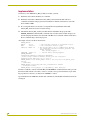
Step 1: Downloading The ALD-H48 Workspace
First you must attain the ALD-H48 Workspace file (.AXW). To download the Duet module go to
either amx.com > Dealers > InConcert or the Product Catalog page for the ALD-H48. From the
InConcert page you can search for and download the ALD-H48 Duet module, they are indicated by
the D within the legend displayed below.
FIG. 1 Module Legend
Included in the .AXW file:
The NetLinx Main Code (.AXS)
The Duet module (.JAR)
Associated TPD4 files
Step 2: Setting The ALD-H48 IP Address
In order for the NetLinx Master to locate the ALD-H48, you must set the IP address for the device.
1. Connect your PC to the H48 serial port using a standard DB-9 serial cable.
2. Open your preferred serial client (HyperTerm, TELNET, etc...)
3. Make sure your serial connection baud rate and handshaking settings match the H48 serial
settings. (Default Baud Rate 9600, Data Bits: 8, Parity: None, Stop Bits: 1, Flow Control:
None)
4. Upon a successful connection, you are prompted with L232>. At the prompt type SETIP,1,
xxx.xxx.xxx.xxx . Follow the onscreen instructions from this point.
(Where 1 is the number of processors present on the H48 and xxx.xxx.xxx.xxx is the IP
address to be decided by you.)
Further, at the prompt type HELP and a list of all supported command is displayed. In order to get
the correct syntax to set the IP address type at the prompt HELP, SETIP.
Step 3: Opening The ALD-H48 Workspace
After you have downloaded the ALD-H48 Workspace file you need to open your NetLinx project.
The .AXW file provided by AMX is intended to be a starting point for your ALD-H48 project.
1. Launch NetLinx Studio v2.3 or higher.
2. Select File > Open Workspace to launch the Open Workspace dialog.
3. Browse to the location where you saved the ALD-H48 Workspace file (.AXW) and click
Open.
4. Manually enter the IP address assigned to the ALD-48 within Lutron_H48_UI.axs and then
recompile the project before transferring it to the NetLinx Master.
ALD-H48 Lighting Controller
3
Getting Started
You can also make any additional edits to the ALD-H48 project or elect to send the file to the
NetLinx Master as is.
There is a "simple" version of the ALD-H48 files. These files are intended for
demonstration purposes only.
Step 4: Transferring The ALD-H48 Project to A NetLinx
Master
NetLinx Studio can transfer the ALD-H48 project file to any connected NetLinx Master with
firmware version 3.XX or higher.
1. Select Tools > File Transfer to open the File Transfer dialog.
2. If the Workspace file is not already listed in the window click Quick Load to open the
corresponding dialog.
3. In the drop down list select the ALD-H48 Workspace.
4. Click Select All.
5. Click OK.
6. Make sure there is a check in the box next to the ALD-H48 workspace within the File Transfer
dialog and click Send.
4
ALD-H48 Lighting Controller
Using The Web Interface
Using The Web Interface
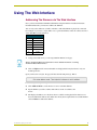
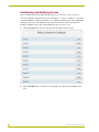
Addressing The Dimmers via The Web Interface
Once you have installed the ALD-H48 and dimmers using the hardware installation literature
included with the unit, you must now address the dimmers.
You can only select addresses available on the bus to which the dimmer is physically connected.
For example, if you want to assign address 17 to a particular dimmer, it must be connected to bus 3
of the ALD-H48 as indicated below.
Bus Address Location
Bus
Address
1
1-8
2
9-16
3
17-24
4
25-32
5
33-40
6
41-48
To address the dimmers:
1. Using your web browser, go to the target NetLinx Master’s web page.
Refer to the NetLinx Master documentation for more detailed information concerning
the NetLinx Master Web Interface.
2. Click on Lights and all connected modules are displayed below Lights. There is only one
module per device.
Upon your first visit to Lights, the page will have the following message, FIG. 2.
FIG. 2 Initial Lights Configuration Page
3. Click Address Mode to set the master to look for available dimmers.
4. Tap the dimmer you wish to address three times to make it available to the
master.
5. The displayed addresses are only those that are available on that physical bus that have not
been used. Bold text indicates the address has already been assigned. Pick an available number
and click Select to address the dimmer.
ALD-H48 Lighting Controller
5
Using The Web Interface
FIG. 3 Dimmer Address
6
ALD-H48 Lighting Controller
Using The Web Interface
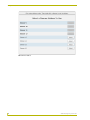
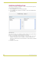
Controlling Dimmers via The Web Page
Once a dimmer has been addressed, you have access to a few basic level controls from the master’s
web page.
1. Click the button Dimmer Control to open the Dimmer Control page. (FIG. 4)
FIG. 4 Dimmer Control
Listed in the column on the left are all dimmer addresses available for control. On the right is a
percentage bargraph representation of the current state of the selected dimmer.
2. To change the state of a dimmer, select a dimmer address in the column on the left.
Click on 100% to ramp the dimmer completely on and 0% to ramp the dimmer off.
Click within the bargraph area on the right to shift the dimmer state up and down to a
desired percentage.
ALD-H48 Lighting Controller
7
Using The Web Interface
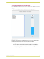
Establishing And Modifying Scenes
Once your dimmers have been addressed and states set, you can create a scene. A scene is a
collection of dimmers with specific states for each dimmer, i.e., Scene 1 could be set as a meeting
scene where Dimmers 1 and 12 ramp down to 45%, Dimmers 6 and 14 ramp to 80% and Dimmers
2 through 5 ramp to 0% and all dimmers delay 10 seconds after the scene is selected before
initiating. A dimmer can be a part of many different scenes. To create a scene:
1. Click the Scenes button at the top of the page. Shown below is the Scene page.
FIG. 5 Scene Page
2. Click the Modify button for the Scene you would like to set. This opens the Modify Scene
page.
8
ALD-H48 Lighting Controller
Using The Web Interface
FIG. 6 Modify Scene
3. Moving left to right the first field is a check box. Placing a check in the box includes the
dimmer in the scene.
Once you have all of your desired dimmers selected you can set the Delay time.
The delay time is the duration, in 1/10ths of seconds, it takes the dimmers to respond to
the button push.
4. Type a number value in the field Delay Time.
The next field is the ramp time.
The ramp time is the duration, in 1/10ths of seconds, it takes the dimmers to go from their
current intensity state to that set in the scene.
5. Type a number value in the field Ramp Time.
The next field is intensity.
Intensity is a percentage value, 0-100%, for the luminosity of the light.
6. Type a number value in the field Intensity.
7. Click Save to set your scene.
Global Adjustment allows you to select and deselect all dimmers at one time, and to set the Delay
Time, Ramp Time and Intensity values for all dimmers, to the same value.
When modifying scenes, ignored dimmers will display their current intensity level while dimmers
included in the scene will display their defined intensity level, not necessarily the current state.
ALD-H48 Lighting Controller
9
Using The Web Interface
Establishing And Modifying Groups
For the purpose of controlling several dimmers at one time you can place them into groups. The
groups can then be manipulated collectively.
1. Click the Groups button to list all available group numbers.
2. Click the Modify button for the Group you would like to set. This opens the Modify Group
page. Shown below.
FIG. 7 Modify Group
In the column on the left is a list of all dimmers available for adding to the group. The column on
the right is a list of all dimmers currently included in the selected group.
3. Select an available dimmer on the left and click the ">" button in the center to move it to the
included list on the right. You can move all dimmers at one time by clicking on the ">>"
button, remove a dimmer from the scene list by clicking the "<" button and remove all dimmers
by clicking "<<".
4. Click Save to set your group.
10
ALD-H48 Lighting Controller
Using The Touch Panel Pages
Using The Touch Panel Pages
Touch Panel Main Page
After you have loaded the Lutron_H48.TP4 sample file, it is displayed on the Main Page (FIG. 8)
of your touch panel. The Main Page is displayed after each subsequent reboot.
FIG. 8 Touch Panel Main Page
Near the bottom of the panel page are the 4 buttons for configuring your system. Click on any of the
buttons to access their pages. The buttons are:
Setup - access addressing mode and set addresses for connected dimmers.
Groups - create dimmer groups and assign ramping for them.
Scenes - create and edit lighting scenes; scenes support intensity, fade time and delay
time.
Keypad - access basic functionality such as ON and OFF, keypads can be customized.
The sample file supports 4 scenes. Click on buttons 1 through 4 to recall a scene.
ALD-H48 Lighting Controller
11
Using The Touch Panel Pages
Dimmer Light Adjustment
The dimmer light adjustment allows you to turn on and off specific dimmers, ramp dimmers up and
down and set dimmers to specific levels between 0 and 100%.
Toggle Dimmer
Ramp Up/Down
Keypad
Dimmer On
Open Keypad
Dimmer Off
FIG. 9 Dimmer Light Adjustment
Toggle Dimmer - moves through all addressed dimmers connected to the ALD-H48.
Dimmer Off - turns the selected dimmer off.
Dimmer On - turns the selected dimmer on.
Ramp Up - click on the button to incrementally raise the dimmer’s intensity.
Ramp Down - click on the button to incrementally lower the dimmer’s intensity.
Open Keypad - opens the keypad to set the dimmer intensity percentage.
Keypad
Enter a percentage for the dimmer intensity.
Go - accepts the percentage value entered.
Del - deletes value entered into the keypad.
Exit - closes the keypad.
To adjust a dimmer:
1. Using the buttons, toggle to the addressed dimmer.
You can turn the dimmer on or off using the Dimmer On and Dimmer Off buttons.
12
ALD-H48 Lighting Controller
Using The Touch Panel Pages
Push the Ramp Up and Ramp Down buttons to raise and lower the dimmer levels
incrementally.
2. Push the "%" button to open the keypad, type the percentage value for the dimmer.
3. Push Go to set the dimmer intensity.
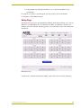
Setup Page
Opening the Setup page places the ALD-H48 in addressing mode which will allow you to allocate
addresses to attached dimmers. It is recommended you address your dimmers at the time your
lighting system is first installed. The Setup page has a total of 48 buttons (8 per each of the 6 buses)
shown below.
FIG. 10 Setup Page
It is important to remember which bus the dimmer is physically connected to when addressing.
ALD-H48 Lighting Controller
13
Using The Touch Panel Pages
Addressing Dimmers
1. From the Main page, push the Setup button.
2. Push the Addressing Off button, this will place the ALD-H48 in addressing mode.
3. Push the dimmer you wish to address three times. The serial number of the dimmer appears at
the bottom of the page as a confirmation.
4. Select the address number for the dimmer. Remember to select the bus to which the dimmer is
physically attached. It is recommended you assign unique names to the address buttons after
you have addressed them.
5. Upon a succesful addressing of a dimmer, a confirmation message is displayed at the bottom of
the page and Addressing mode is turned off automatically Otherwise, an error message is
displayed.
If you select the wrong bus the addressing fails to assign.
Setting Unique Names
1. Press the dimmer address button for three seconds.
2. Type the name you wish to assign to the button.
3. Press Done to save and exit.
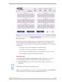
Groups Page
The Groups page allows you to set and edit dimmers into groupings of several dimmers.
Represented on the page is 48 buttons for each possible dimmer, grouped according to
corresponding buses. The buttons are either numbered, or custom labels if assigned.
14
ALD-H48 Lighting Controller
Using The Touch Panel Pages
FIG. 11 Groups Page
The sample touch panel only includes support for 2 groups but the system supports 48 groups.
There is a limited amount of editing functionality available on the test pages. While it is not
possible to delete a group from this page once the group has been established, you can overwrite an
existing group.
To Group 1 - Open control of dimmers associated with Group 1.
To Group 2 - Open control of dimmers associated with Group 2.
Reset - Clears selected dimmers from the group and returns it to the last saved state.
Level Up/Down - Ramps the selected group up and down.
Creating A Group
1. Push either button To Group 1 or To Group 2, depending on which one you want to set.
2. Push the address buttons for all of the dimmers you want included in the group.
3. Push the To Group... button previously selected in Step 1. The page then gives you a
confirmation.
Setting a group overwrites any previous group settings.
While you are selecting dimmers for a group you can deselect all addresses by pushing the Reset
button, this will not remove dimmers already established within that group.
ALD-H48 Lighting Controller
15
Using The Touch Panel Pages
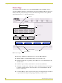
Scenes Page
Accessing the Scenes page allows you to create and edit lighting scenes. A lighting scene is a
collection of dimmers changing to specific intensity percentages (0-100%), fading in or out (up to 1
minute) and having a delay time (up to 2 hours). All of the Scene parameters come together for
specific lighting needs, i.e., a slideshow presentation.
Bus Toggle
Dimmer Addresses
Intensity Level
Fade Time
Delay Time
Delete Scene Button
Back Button
Scene Preset Buttons
FIG. 12 Scenes Page
Bus Toggle - Push the Up and Down arrows to select the Bus of dimmers.
Dimmer Addresses - Push the dimmer address to be set into the scene.
Intensity Level - Based on a percentage of 0 - 100%, raise or lower the intensity for the
selected dimmer.
Fade Time - Up to 1 minute, set the fade in or out for the selected dimmer.
Delay Time - Set the amount of time, up to 2 hours, the dimmer delays before initiating
its intensity and fade sequence. If the delay time is set lower than 0 minutes, the time
defaults to 120 minutes.
Scene Preset Buttons - Scene selection for the purpose of editing. Push any scene button
to open and edit. The sample touch panel page provides you with 4 scenes.
16
ALD-H48 Lighting Controller
Using The Touch Panel Pages
Delete Scene Buttons - Push the button to remove all dimmers and settings for the
dimmers. This removes everything contained within the scene.
Back Button - Return to the Main page.
Creating A Lighting Scene
1. From the Main page, push the Scenes button.
2. Select the scene you want to configure, push the To Scene... button.
3. Push the Bus Toggle buttons until you find the bus that hold the dimmer you want included in
the scene.
4. Push the button address for the dimmer you want in the scene.
5. Using the Intensity Level, Fade Time and Delay Time buttons, set the parameters for the
dimmer.
6. Push the To Scene... button selected in step 2.
Deleting A Lighting Scene
1. From the Main page, push the Scenes button.
2. Select the scene you want to delete, push the To Scene... button.
3. Push the Delete Scene button. This removes all information and dimmers contained within this
scene.
ALD-H48 Lighting Controller
17
Using The Touch Panel Pages
18
ALD-H48 Lighting Controller
Advanced Programming
Advanced Programming
Introduction
This is a reference manual to describe the interface provided between an AMX NetLinx system and
a Lutron H48 Lighting Controller. The H48 supports an IP protocol. Further, the H48 supports 48
light loads (dimmers) and 24 keypads (addressable as keypad 1 through 24).
Overview
The COMM module translates between the standard interface described below and the H48
protocol. It parses the buffer for responses from the H48, sends strings to control the H48 and
receives commands from the UI module or telnet sessions.
A User Interface (UI) module is also provided. This UI uses the standard interface described below
and it parses the command responses for feedback.
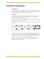
The following diagram gives a graphical view of the interface between the interface code and the
Duet module.
NetLinx
Virtual
UI Module
Device
Duet
SNAPI
COMM
Module
Lutron H48
FIG. 13 Interface between code and NetLinx module
Some functionality in the device interface may not be implemented in the API interface. In cases
where device functions are desired but not API supported, the PASSTHRU command may be used
to send any and all device-protocol commands to the device. See the PASSTHRU command and the
Adding Functions to Modules section on page 36 for more information.
A sample UI module and a touch panel file are provided in the module package. These are not
intended to cover every possible application, but can be expanded as needed to meet the
requirements of a particular installation.
ALD-H48 Lighting Controller
19
Advanced Programming
Implementation
To interface to the AMX Lutron_H48_Comm.jar module, you must:
1. Define the device ID for the H48 to be controlled.
2. Define the virtual device ID that the Lutron_H48_Comm.jar Duet module will use to
communicate with the main program and User Interface. NetLinx virtual devices start with
device number 41001.
3. If a touch panel interface is needed, a touch panel file Lutron_H48.TP4 and module
Lutron_H48_UI.axs have been created for testing.
4. The NetLinx Lutron_H48_Comm.jar module must be included in the program with a
DEFINE_MODULE command. This command starts execution of the module and passes in
the following key information: the device ID of the H48 to be controlled, and the virtual device
ID for communicating to the main program.
An example of how to do this is shown below.
DEFINE_DEVICE
dvReal
=0:5:0
dvTP
=128:1:0
vdvLutron =41001:1:0
// The real H48 connected to the NetLinx IP port
// The touch panel used for output
/* The virtual device use for communication between
the Comm module interface and User_Interface (UI)
module interface.
Also used by keypad 1. */
// Virtual device used by keypad 2.
vdvKeypd2 =41001:2:0
DEFINE_VARIABLE
VOLATILE DEV vdvArray[]={vdvLutron,vdvKeypd2}
//Define arrays of button channels used on your own touch panel
VOLATILE integer nButtons[]={1,2,3,4,5,6,7}
DEFINE_START// Place define_module calls to the very end of the define_start
section.
// Comm module
DEFINE_MODULE 'Lutron_H48_Comm' duet_code(vdvLutron, dvReal)
// Touch panel module
DEFINE_MODULE 'Lutron_H48_UI' ui_code(vdvArray, dvTP, nButtons)
In order to establish a connection with the H48, the PROPERTY- command must be used to provide
the Duet module with the correct IP to connect to, and the correct password needed to login. After
the properties have been set, you must issue a REINIT to connect.
Upon initialization the AMX Duet module will communicate with the H48 and information will be
exchanged.
20
ALD-H48 Lighting Controller
Advanced Programming
Port Mapping
This module uses multiple virtual devices in order distinguish events for one keypad from another.
Port Mapping
Virtual Device
Channels
Levels
Control
Feedback
41001:n:0 - {keypad n=1..24}
1..24
&
101..124
none
PUSH
RELEASE
ON
OFF
FLASH
Channel Assignment and Feedback
While channel 251 is ON, the AMX system and the H48 are communicating.
While channel 252 is ON, the Duet module has been initialized with the latest H48 data.
Each keypad added to the keypad component list (see KEYPADADD-<index>,<addr> command)
is controlled by turning a channel ON/OFF or by generating a button PUSH/RELEASE similar to a
Netlinx native device. The virtual device you assign in your project will be used to accomplish this
as follows: the virtual port number of your virtual device's D:P:S will represent the keypad number
(1..24) and the channel will represent the keypad button (1..24). Most keypads, at this time, have a
maximum of 10 LEDs, so LEDs 11 through 24 will not have a visual notification in this case, but
they will have a virtual notification. The table below shows the mapping of channels to keypad
buttons/LEDs. Ports 1 through 24 and channels 1 through 24 on each port are used and cannot be
changed. To indicate a flashing LED, channels 101..124 are used.
Example of use: Suppose you assign a virtual device number 41001:1:0 in your application code.
All commands to and from the Duet code will use this virtual device as usual. If so desired,
additional keypad control can be accomplished by turning ON/OFF channels or by doing a PUSH/
RELEASE. So, suppose you turn ON channel 4 on virtual device 41001:1:0, then this will turn ON
the LED on keypad 1 button 4. If you want to turn OFF the LED on keypad 5 button 7, then all you
have to do is turn OFF channel 7 on virtual device 41001:5:0. As you can see, the port number is
used to tell what keypad to control and the channel is used to tell what button to affect. Similarly, if
someone turns ON the LED on keypad 5 button 7, then channel 7 on virtual device 41001:5:0 will
turn ON. The keypad LEDs can be turned OFF or ON, and the keypad buttons can be PUSHed or
RELEASEd in this way. You may also FLASH a specific keypad LED. In order to flash you must
turn ON the matching channel+100. In other words, if you would like to flash keypad LED number
7 then turn ON channel 107. To stop flashing you must turn off the channel described in the below
table, so for the above example, you would turn OFF channel 7. To transition from FLASH to ON
in the above example, you must first turn OFF channel 7, and then turn channel 7 back ON.
The keypad number is the number assigned to each keypad by making the
appropriate dipswitch assignments on the back of it. If looking at the protocol
document, the last address parameter (i.e. [1:5:x] x = keypad number)
ALD-H48 Lighting Controller
21
Advanced Programming
Channel Assignment and Feedback
CH
22
Keypad Button (PUSH/RELEASE)
Keypad LED (ON/OFF)
CH+100 (used for flashing)
1
1
1
101
2
2
2
102
3
3
3
103
4
4
4
104
5
5
5
105
6
6
6
106
7
7
7
107
8
8
8
108
9
9
9
109
10
10
10
110
11
11
11
111
12
12
12
112
13
13
13
113
14
14
14
114
15
15
15
115
16
16
16
116
17
17
17
117
18
18
18
118
19
19
19
119
20
20
20
120
21
21
21
121
22
22
22
122
23
23
23
123
24
24
24
124
ALD-H48 Lighting Controller
Advanced Programming
Command Interface
The interface code controls the lighting controller via command events (NetLinx command
send_command). These commands are sent to the Duet module to affect control. Below are the
commands supported. In order to be able to control a specific lighting component (dimmer/keypad)
you must first add that component to the list of components to track. See LIGHTADD<index>,<addr> and KEYPADADD-<index>,<addr>.
* Denotes an extended/advanced command beyond the standard API.
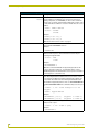
Command Interface
Command
*
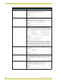
ADDRESSING-<state>
Description
Place the H48 in addressing/programming mode. This mode is used
to program a Dimmer address. Once the H48 is in addressing mode,
triple-tap the dimmer you want to set the address for, and use the
SETADDRESS- command to set the address of that Dimmer.
<state>: 1=ON
0=OFF
Example:
ADDRESSING-1
*
?ADDRESSING
Query the addressing/programming state of the H48.
Responds with ADDRESSING-<state>
Example:
?ADDRESSING
CLOCK-<mm/dd/yyyy>
<hh:mm:ss>
Set the device date/time. For time use military format.
Example:
CLOCK-12/10/2004 13:05:50
*
?CLOCK
Query for the date/time.
Example:
?CLOCK
DEBUG-<value>
Enables or disables the debug feature.
<value>: 1 = Error
2 = Warning
3 = Debug
4 = Info
DEBUG=1 (default)
?DEBUG
Request the state of the debug feature.
* DELSCENE-<sceneNmbr>
Deletes a scene.
?DEBUG
<sceneNmbr>: 1..48
Example:
DELSCENE-1
ALD-H48 Lighting Controller
23
Advanced Programming
Command Interface (Cont.)
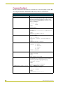
Command
*
Description
DIMMERFLASH-<addr>, This command will start flashing every 2 seconds the dimmer with the
<state> specified address. This Dimmer does not have to be in the list of
lighting components (see LIGHTADD-) in order for this command to
execute. This is a useful command while installing the system in order
to tell/confirm where a Dimmer is located or whether it has the correct
address.
<addr>: Dimmer address
<state>: 1=START
0=STOP
Example:
FLASH-[1:4:1:1:1],1
FLASH-[1:4:1:1:1],0
Note: See the Device Notes section on page 33
?FWVERSION
Query for the device firmware version.
Responds with FWVERSION-<version>
Example:
?FWVERSION
*
KEYPADENABLE-<state>
Enable or disable a specific Keypad. If this command is sent to a
Dimmer, it will not process. This command is issued on the port
matching the keypad number.
<state>: 1=ON
2=OFF
Example:
KEYPADENABLE-1
KEYPADENABLE-2
Note: This command will disable the physical keypad, but not the
control of it from the module (i.e. you will still be able to control a
disabled keypad from the module, but if someone presses the buttons
on that keypad, no control will occur).
KEYPADADD-<index>,<addr> This command will add a keypad to the list of keypad components to
track. Each keypad must be added to this list if you want to control it
or received any feedback from it.Each keypad must be added to the
correct index. The index must match the keypad number/ID established with the keypad’s dip switches. Also see KEYPADREMOVEIDX
and KEYPADREMOVEADDR.This command is always issued on port
1.
<index>: 1..24 = valid index/port for the
keypad
<addr>: keypad address
Example:
?KEYPADADDR-<index>
KEYPADADD-1,[1:5:1]
(keypad 1 to index 1)
KEYPADADD-4,[1:5:4]
(keypad 4 to index 4)
Get the keypad address for the specified index. This command is
always issued on port 1.
<index>: 1..24 = index to query
Example:
?KEYPADADDR-1
24
ALD-H48 Lighting Controller
Advanced Programming
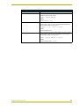
Command Interface (Cont.)
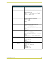
Command
?KEYPADIDX-<addr>
Description
Get the keypad index for the keypad address specified. This
command is always issued on port 1.
<addr>: keypad address
Example:
?KEYPADIDX-[1:5:1]
KEYPADREMOVEIDX-<index>
Remove a keypad component from the list. Once removed, you will no
longer be able to control or receive any feedback from that keypad.
This command is always issued on port 1.
<index>: 1..24 = index to remove
Example:
KEYPADREMOVEIDX-1
KEYPADREMOVEADDR-<addr>
Remove a keypad component from the list. Once removed, you will no
longer be able to control or receive any feedback from that keypad.
This command is always issued on port 1.
<addr>: keypad address to remove
Example:
KEYPADREMOVEADDR-[1:5:1]
ALD-H48 Lighting Controller
25
Advanced Programming
Command Interface (Cont.)
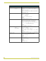
Command
LIGHTADD-<index>,
[<grp>:]<addr>
[;<addr>]
Description
This command will add a lighting component (a Dimmer, a group, or a
scene) to the list of components to track. In order to receive any feedback or control a specific lighting component you must add each individual component (dimmer) to the list. You can however, control a
scene or a group w/o adding all it's corresponding dimmers to this list,
but no scene/group feedback will be received. Duplicate entries (identical address) are ignored.You may provide up to and including 10
dimmer component addresses per index (this is a group) by separating the addresses with a ";". Groups do not receive any feedback;
instead the individual lighting components (the dimmers) that are part
of the group will receive feedback as long as they have been added to
the list of individual components to track. Also see LIGHTREMOVEIDX and LIGHTREMOVEADDR.
<index>: 1..n = index to add the lighting
component to.
<grp>: 1..48 = Group Number. Each group must
be assigned a unique identifier.
Applicable to groups only.
<addr> : Dimmer, Group or Scene Address.
Examples:
//Add address [1:4:1:1:1] to index 1. If something was stored
// at index 1 before, it will be replaced.
LIGHTADD-1,[1:4:1:1:1]
// This will place [1:4:1:2:1] at index 2 for example.
LIGHTADD-2,[1:4:1:2:1]
//Add address [1:4:1:1:1] and [1:4:1:2:1] to index 3(Group 6)
LIGHTADD-3,6:[1:4:1:1:1];[1:4:1:2:1]
// This will place scene 1 at index 4.
LIGHTADD-4,[1]
• In order to add a scene to the list, simply use the scene number as
the <addr>.
• When adding a group you must specify a unique group number.
This identifier is needed only for groups.
• In the above example the lighting component list will end up having
4 items in it. The first 2 items are the 2 individual dimmers to track,
and the last 2 items are the group and the scene.
?LIGHTADDR-<index>
Query for the address of the lighting component at a specific index.
Responds with LIGHTADDR-<index>,<addr>
<index>: 1..n
Example:
?LIGHTADDR-1
?LIGHTIDX-<addr>
Query for the index of the lighting component with the specified
address.
The <addr> must match exactly and always use [] when specifying an
address for all components.
Responds with LIGHTADDR-<index>,<addr>
<addr>: light address
Example:
?LIGHTIDX-[1:4:1:1:1] // at what index is this address stored
?LIGHTIDX-[1]
// at what index is scene 1 stored
26
ALD-H48 Lighting Controller
Advanced Programming
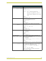
Command Interface (Cont.)
Command
Description
Set the Dimmer level or the group of dimmers level.
LIGHTLEVEL-<index>,
<level>[,<time>] <index>: 1..n
<level>: 0..255
<time> : 0..n = Optional parameter.
Specifies the length of time, in
seconds, the dimmer will take to
fade from the current level to the
target level. Defaults to 0 if not
used.
Example:
LIGHTLEVEL-1,102
?LIGHTLEVEL-<index>
Query for the level of a Dimmer at the specified index.
Responds with LIGHTLEVEL-<index>,<level>
<index>: 1..n
Example:
?LIGHTLEVEL-1
LIGHTRAMP-<index>,
<state>
Ramp the Dimmer or group of dimmers at the specified index.
<index>: 1..n
<state>: UP, DOWN, STOP
Example:
LIGHTRAMP-1,UP
LIGHTRAMP-1,STOP
LIGHTREMOVEIDX-<index>
Remove the lighting component at the specified index.
Also see LIGHTADD-.
<index>: 1..n
Example:
LIGHTREMOVEIDX-2
LIGHTREMOVEADDR[<Grp>:]<addr>[;<addr>]
Remove the lighting component with the specified address. The
address must match exactly (including addresses order for groups) in
order to have a successful remove.
Also see LIGHTADD-.
<Grp>: 1..48 = group label. Used only if removing a group.
<addr>: address to remove
Example:
LIGHTREMOVEADDR-1:[1:4:1:1:1];[1:4:1:2:1] (removes the group)
LIGHTREMOVEADDR-[1:4:1:1:1]
(removes the individual dimmer)
LIGHTSTATE-<index>,
<state>
This will turn On, Off, or Toggle a specific Dimmer. If used with a
scene, only On (recall) is applicable. Does not apply to Keypads. If
this command is sent to a Keypad it will not process.
<index>: 1..n = index of the Dimmer to
control
<state>: ON, OFF, TOGGLE
Example: (assuming that there is a Dimmer stored at index 1)
LIGHTSTATE-1,TOGGLE
ALD-H48 Lighting Controller
27
Advanced Programming
Command Interface (Cont.)
Command
?LIGHTSTATE-<index>
Description
Query for the state of a dimmer at the specified index.
Responds with LIGHTSTATE-<index>,<state>
<index>: 1..n
Example:
?LIGHTSTATE-1
PASSTHRU-<buffer>
Send a message directly to the device. The module will not add any
characters to this pass thru string. User must be aware of the exact
H48 protocol in order to use this command.For more information see
Adding Functions to Modules section on page 36.
<buffer>: exact H48 command string
Example:
PASSTHRU-FADEDIM, 100, 1, 2, [1:4:1:1:1]
PROPERTY-<key>,<value>
Sets the IP and Password to be used by the Duet module in order to
establish IP communications with the H48. This method does not
actually set the IP or Password on the actual device. This command
can also set the "friendly name"for the configuration servlet/webpage.
<key>: IP_Address
(case sensitive)
Password
(case sensitive)
FriendlyName
(case sensitive)
<value>: value of the key.
(case sensitive)
Example:
PROPERTY-IP_Address,10.0.0.5
PROPERTY-Password,jetski
Note: The Duet module uses a default password of "amx01"(without
the quotes). Please change the password property according to your
needs, but DO NOT use a password that contains a "," (comma) in it
or you will not be able to establish an IP connection to the H48.
You must issue a REINIT in order for the new properties to take affect.
?PROPERTY-<key>
Query for the value of a certain key. Replies with PROPERTY<key>,<value>.
<key>: IP_Address
Password
Example:
?PROPERTY-IP_Address
REINIT
Reinitialize H48 IP communications. The communication module will
then query the H48 for the state of all known (found in the component
list. See LIGHTADD- and KEYPADADD- commands.) dimmers and
keypads.
REINIT
*SETADDRESS-<addr>
Sets the address of the triple-tapped dimmer. The H48 must be in
programming/addressing mode in order for this command to take
affect. Make sure your dimmer is on the correct bus.
<addr>: dimmer address to assign
Example:
SETADDRESS-[1:4:1:1:1]
28
ALD-H48 Lighting Controller
Advanced Programming
Command Interface (Cont.)
Command
* SETSCENE-<sceneNmbr>,
<Addr/index>,
<level>,
<FadeTime>,
<DelayTime>
Description
Sets a scene. Adds (appends) a dimmer to the scene. You may add
each dimmer as a separate item in the scene or add up to and
including 10 dimmers as the same item in the scene.
If several dimmer addresses are added as the same item in the
scene, their addresses must be separated by a semicolon (;).By
adding each dimmer as a separate item in the scene, when the scene
is recalled, it will execute each item sequentially. This is beneficial
because it can execute a large number of commands (similar to a
macro) with different <level>, <FadeTime>, and <DelayTime> values,
however, the commands are not executed simultaneously. By adding
up to 10 dimmers as the same item in the scene, when the scene is
recalled, it will change the settings of the dimmers simultaneously. A
drawback is the limited number of dimmers that can be added this
way (up to 10) and the fact that the same <level>, <FadeTime>, and
<DelayTime> will be used for all of them.
<sceneNmbr>: 1..48 = scene number to set
<Addr/index>: Dimmer Address(es) or lighting
component Index to add to
scene.
<level>: 0..255 = light level to go to.
<FadeTime>: 0..n = time, in seconds, to reach
desired level.
<DelayTime>: 0..n= time, in seconds, to delay
execution.
Example:
SETSCENE-1,2,230,5,1
(add component index 2 to scene 1)
SETSCENE-1,[1:4:1:1:1],200,3,2
(add a separate dimmer item)
SETSCENE-1,[1:4:1:2:1];[1:4:1:2:2],156,0,0
?VERSION
Query for the module version.
Responds with VERSION-<version>
Example:
?VERSION
ALD-H48 Lighting Controller
29
Advanced Programming
Command Feedback
The Duet module will provide feedback to the user interface code for the lighting controller. Here
are the supported feedback commands. The feedback is provided via command events.
Command Feedback
String
ADDRESSING-<state>
Description
Feedback for the H48 addressing/programming mode. This
mode is used to program a Dimmer address. Once the H48 is in
addressing mode, triple-tap the dimmer you want to set the
address for and use the SETADDRESS- command to set the
address of that Dimmer.
<state>: 1=ON
2=OFF
Example:
ADDRESSING-1
CLOCK-<mm/dd/yy> <hh:mm:ss> Reports the current date and time. Time is reported in military
format. This reply is received whenever a ?CLOCK query has
been issued.
Example:
CLOCK-01/12/2005 13:20:12
CONNECT-<ip>,<message>
Connection feedback.
<ip>: IP address
<message>: Success, Invalid Password
Example:
CONNECT-10.0.0.5,Success
DEBUG=<value>
Feedback for the debug feature.
<value>: 1 = Error
2 = Warning
3 = Debug
4 = Info
DEBUG=1 (default)
DATE-<date>
Feedback for the date.
<date>: string
Example:
DATE-Friday 12/10/2004
ERROR-<message>
Unsolicited feedback received whenever the module has encountered a problem such as assigning the wrong bus number to a
dimmer during the addressing/programming stage.
<message>: string
Example:
ERROR-Unrecognized Command.
DIMMERFLASH-<addr>,<state>
Reply to a DIMMERFLASH- command.
<addr>: Dimmer address
<state>: 1=START
Example:
DIMMERFLASH-[1:4:1:1:1],1
30
ALD-H48 Lighting Controller
Advanced Programming
Command Feedback (Cont.)
String
FWVERSION-<version>
Description
Reply to the device firmware version.
Example:
FWVERSION-Processor 01 O/S Rev : 01.01.01 T26
KEYPADBTN-<btn>,
<state>
Reply received when a keypad button has been doubletapped.This reply is received on the port matching the keypad
number that cause the event.
<btn>
:
<state>:
1..24 = keypad button number
DOUBLE_CLICK
Example:
KEYPADBTN-1,DOUBLE_CLICK
KEYPADENABLE-<state>
Feedback for the Keypad state. This feedback is received on the
virtual device port matching the keypad number.
<state>: 1=ON
0=OFF
Example:
KEYPADENABLE-1
KEYPADADDR-<index>,<addr>
Feedback for the current index to Keypad address
assignment.This feedback is always issued on port 1.
<index>:
0 = not assigned
1..24 = assigned index/port
<addr>: Keypad address (blank if no address assigned)
Example:
KEYPADADDR-3,[1:5:3]
LIGHTADDR-<index>,<addr>
Feedback for the current index to Dimmer/Group/Scene address
assignment.
<index>:
0 = not assigned
1..n = assigned index
<addr>: Dimmer address, Group addresses, or Scene number
(blank if no address assigned)
Example:
LIGHTADDR-1,[1:4:1:1:1] // at index 1 we have a dimmer
LIGHTADDR-4,[1]
// at index 4 we have scene 1 stored.
LIGHTLEVEL-<index>,
<level>
Reply for the Dimmer level.
<index>: 1..n
<level>: 0..255
Example:
LIGHTLEVEL-1,102
LIGHTRAMP-<index>,
<state>
Feedback for the Dimmer ramping state.
<index>: 1..n
<state>: UP, DOWN, STOP
Example:
LIGHTRAMP-1,UP
LIGHTRAMP-1,STOP
ALD-H48 Lighting Controller
31
Advanced Programming
Command Feedback (Cont.)
String
LIGHTSTATE-<index>,
<state>
Description
Feedback for the Dimmer state.
<index>: 1..n = index of the Dimmer
<state>: ON, OFF
Example: (assuming that there is a Dimmer stored at index 1)
LIGHTSTATE-1,ON
PROPERTY-<key>,<value>
Feedback for the property query.
<key>: IP_Address
Password
<value>: actual key value
Example:
PROPERTY-Password,jetski
SERIALNUMBER-<number>,<bus> This reply is received while the H48 is in programming mode and
a dimmer has been triple-tapped. This reply will notify you of the
dimmer's serial number that has been triple-tapped.
<number>: serial number of the triple-tapped dimmer
<bus>: 1..6 = bus number dimmer is on
0
= invalid/unrecognized bus
Example:
SERIALNUMBER-12466768689,1
SETADDRESS-<state>,
<addr>,
<serialNum>
Reply received after a successful dimmer address assignment.
<state>: SUCCESS
<addr>: new dimmer address
<serialNum>: serial number of the dimmer
Example:
SETADDRESS-SUCCESS,[1:4:1:1:1],12466768689
TIME-<time>
Feedback for the current time. Military time format. This reply is
received asynchronously approx. every 1 minute.
<time>: string
Example:
TIME-13:24:10
VERSION-<version>
Feedback for the module version.
<version> string
Example:
VERSION-1.0.0
32
ALD-H48 Lighting Controller
Advanced Programming
Device Notes
DO NOT attempt to open more than one client to the H48 box at one time. If the AMX system is
already connected to the H48, please disconnect the AMX system first before attempting to open up
another client (by using TELNET or HyperTerm…) to the H48. There is no support for multiple
clients on the H48. If you do connect another client to the H48 while the AMX system is actively
connected, the AMX connection will be terminated and the Duet module will attempt to reconnect.
Once AMX is able reconnected, the second client will be terminated.
While ramping a Dimmer level, the actual level value is not reported until you have stopped
ramping.
While issuing delayed lighting commands (such as a scene command perhaps), a light may be
reported as On even though the actual physical light will not turn On until the delay time has
expired.
While the H48 is in addressing/programming mode you cannot control any dimmers.
The DIMMERFLASH command seems to behave unexpectedly under the following conditions:
1. If a Dimmer address was just set for the first time, then by issuing a DIMMERFLASH Off
command, the dimmer will toggle On/Off. If a DIMMERFLASH On command is issued, then
the dimmer will properly start flashing. From that point on the DIMMERFLASH Off will work
correctly.
2. If a dimmer address that has not been installed is used to issue a DIMMERFLASH Off
command, the H48 will sometime report that dimmer as actively flashing. This seems to be an
issue related to the current H48 firmware. You should not issue a DIMMERFLASH command
to a non-existent (not installed) dimmer address.
ALD-H48 Lighting Controller
33
Advanced Programming
Programming Notes
The Duet communication module implements a queue for sending commands to the device. A
command will wait for the previous command to receive a reply before it is processed. If a
command does not receive a reply within the timeout period, the device is declared offline, the
queue is cleared of any commands remaining, and the module will attempt to reconnect. The
timeout period is 10 seconds.
The Duet module supports passwords that DO NOT include a comma "," as part of the password
string. By default the Duet module will use "AMX,Inconcert" (without the quotes) as the default
password, but this password should be changed in order to match the password on your H48. If the
password is changed from the default, the new password cannot contain a comma ",".
In order to control a specific lighting or keypad component you must address it by its corresponding
index. This index is established by using the LIGHTADD- or KEYPAD- commands. At that time
the index specified will be mapped to the lighting component's address, and all commands or
feedback will be reported by using this index number. The module maintains two lists of indexes.
One for keypads and another one for lights (dimmers, scenes, or groups of dimmers).
All keypad setup commands (such as adding/removing a keypad to the keypad component list) are
always issued on port 1. All keypad commands have the valid port(s) documented for each keypad
command.
There are 48 scenes supported by the Duet communication module and 48 groups. Each group can
have a maximum of 10 dimmers and each scene can have any number of dimmers (within reason
and memory available).
The Duet communication module will auto-detect a loss of connection to the H48 and will attempt
to re-establish communications. In some cases it may take up to 60 seconds for the Duet module to
do this. The connection state is indicated by channel 251 on the virtual device used in the
application code.
The Lutron H48 communicates on IP port 23 (TELNET). Upon a successful connection to the H48,
the Duet communication module will initialize by turning Off the addressing/programming mode
(if the H48 was in this state at connection time), will issue a query to the H48 in order to determine
what dimmers are physically installed, and will issue queries for the state of all dimmers and
keypads that the communication module is aware of. In order for the communication module to be
aware of a dimmer or keypad, the specific dimmer or keypad must be added to the list of lighting
components to track (see LIGHTADD-<index>,<addr> and KEYPADADD-<index>,<addr>
commands). Once stored in this list, it will be remembered even after a reboot/power cycle of the
AMX system. To manually reinitialize the system, use the REINIT command. This initialization
routine takes approx. 25 seconds (may be higher if the system is fully loaded). The initialization
state is indicated by channel 252 on the virtual device used in the application code.
The Duet communication module writes files to the user directory on the master. These files, called
<vdev>_LightAddressConfig.txt and <vdev>_KeypadAddressConfig.txt,
store the addresses of all components being tracked (the <vdev> parameter is your virtual device
number used). You may manually edit these files, if you want, but care should be taken while doing
so. Each line must end with a carriage return and a line feed. If several dimmer addresses are used
on the same line, a semicolon(;) must separate each address and a group number must be assigned,
with a maximum of 10 addresses per line (this represents a group). If an address consists of only a
number, then that signifies a scene number (i.e. [x] where x is some number). The index of the
34
ALD-H48 Lighting Controller
Advanced Programming
lighting component is represented by the first parameter on each line, followed by a single space,
and then the address.
Here is an example of what the data in this file may look like:
4
3
2
1
[1:4:1:1:1]
[1:4:1:1:2]
1:[1:4:1:1:1];[1:4:1:1:2]
[1]
This configuration file is read only at reboot of the AMX system.
The Duet communication module also writes a file for each scene configured through the AMX
system. Each scene file is called <vdev>_Scene_X.txt, where X is the scene number and <vdev> is
your virtual device number. The data stored in this file matches the syntax of the FADEDIM
command documented in the H48 protocol document except that if several dimmer addresses are
specified on the same line, they must be separated by semicolons (;) instead of commas (,). A
maximum of up to an including 10 addresses can be specified per line. Each line must end with a
carriage return and line feed and there must be a single space after each comma. It is recommended
that you do not manually edit these files. It is recommended that you copy your scene configuration
files, once you have configured the scenes, as a backup. Here is an example of what the data in
these files may look like:
FADEDIM, 100, 00:00:05, 00:00:03, [1:4:1:1:1]
FADEDIM, 95, 00:01:08, 00:00:03, [1:4:1:1:2]
FADEDIM, 55, 00:00:28, 00:00:02, [1:4:1:1:3];[1:4:1:1:4];[1:4:1:1:5]
The sample user interface and touch panel file are provided as an example only and are not to be
used as is in an actual installation. This sample code assumes certain things, documented in the
sample source code, therefore code changes must be made in order to meet your specific
installation requirements. This sample code should be used as a guide/code example for developing
your own user interface.
The Duet communication module will report the time every 1 minute as well as the date.
If the AMX system is rebooted while connected and logged in to the H48, the TCP/IP link may
need to timeout before another connection can be re-established by using the CONNECTcommand. This timeout period is about 1-2 minutes. If both the AMX system and the H48 are
rebooted, then there is no timeout period. The Duet module will continuously attempt to establish a
connection to the H48 as long as the password used in not reported as invalid.
ALD-H48 Lighting Controller
35
Advanced Programming
Adding Functions to Modules
Commands to The Device
This module supplies a mechanism to allow additional device features to be added to software
using the module. This is the PASSTHRU command, which allows protocol strings to be passed
through the module. The device-specific protocol must be known in order to use this feature.
As an example, suppose that a module for a projector has not implemented the 'white balance
adjustment' feature. The command that the projector protocol requires is 03H, 10H, 05H, 14H,
followed by a checksum. The documentation for the PASSTHRU command specifies that the
module will automatically generate the checksum. In this case, the following string should be sent
from the UI code to implement 'white balance adjustment'.
send_command vdvDevice, "'PASSTHRU-',$03,$10,$05,$14"
The reason to use PASSTHRU instead of sending a protocol string directly to the device port is that
the device may require command queuing, calculation of checksums, or other internal processing,
which would not be done if the string was sent directly. Because of this, it is best to filter all
communication TO the device through the module. (The module documentation will indicate any
processing that will be automatically done to the PASSTHRU string like checksum calculation.)
36
ALD-H48 Lighting Controller
Updating The ALD-H48 Firmware
Updating The ALD-H48 Firmware
In the event you need to update the firmware on the ALD-H48:
Via 232
1. Connect at 115200/8/n/1/Hardware
2. At the "L232>" prompt
Send the "UPDATEINOS" command.
3. At the "OSM>" prompt
a. Send the "OSLOAD" command.
b. Transfer the "osif3.asc.bin" file via Y-Modem
4. After receiving "**********"
Transfer the "hw_oper3.hwi.bin" file via Y-Modem
5. At the OSM prompt
Send the "OSPGM" command
6. Processor will then reboot and you will see modem init string
"AT&F1E0F1Q1S0=1M0&C0&D0"
Via Ethernet:
1. Connect via telnet
2. At the "LNET>" prompt
Send the "UPDATEINOS" command.
3. Open FTP connection (username: "lutron" password: "amx01")
4. Send FTP command "ALLO [file size of osif3.asc.bin]"
5. Send FTP command "STOR osif3.dat"
Transfer "osif3.asc.bin" as "osif3.dat"
6. Send FTP command "ALLO [file size of hw_oper3.hwi.bin]"
7. Send FTP command "STOR hw_oper3.hwi"
Transfer "hw_oper3.hwi.bin" as "hw_oper3.hwi"
8. Close FTP connection
9. At "LNET:OSM>" prompt in telnet
Send "OSPGM" command
10. Processor will reboot (telnet connection will be dropped).
ALD-H48 Lighting Controller
37
ARGENTINA • AUSTRALIA • BELGIUM • BRAZIL • CANADA • CHINA • ENGLAND • FRANCE • GERMANY • GREECE • HONG KONG • INDIA • INDONESIA • ITALY • JAPAN
LEBANON • MALAYSIA • MEXICO • NETHERLANDS • NEW ZEALAND • PHILIPPINES • PORTUGAL • RUSSIA • SINGAPORE • SPAIN • SWITZERLAND • THAILAND • TURKEY • USA
ATLANTA • BOSTON • CHICAGO • CLEVELAND • DALLAS • DENVER • INDIANAPOLIS • LOS ANGELES • MINNEAPOLIS • PHILADELPHIA • PHOENIX • PORTLAND • SPOKANE • TAMPA
3000 RESEARCH DRIVE, RICHARDSON, TX 75082 USA • 800.222.0193 • 469.624.8000 • 469-624-7153 fax • 800.932.6993 technical support • www.amx.com
Last Revision: 05/11/05
043-004-2873 5/05 ©2005 AMX Corporation. All rights reserved. AMX, the AMX logo, the building icon, the home icon, and the light bulb icon are all trademarks of AMX Corporation.
In Canada doing business as Panja Inc.
AMX reserves the right to alter specifications without notice at any time.