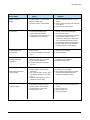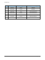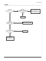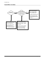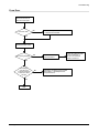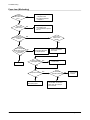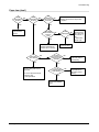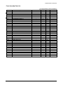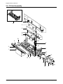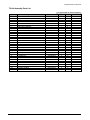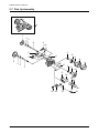
1
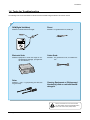
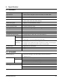
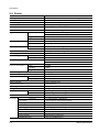
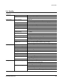
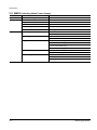
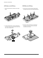
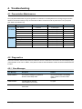
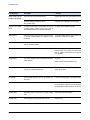
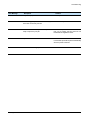
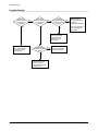
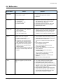
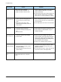
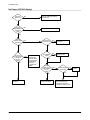
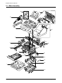
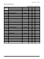
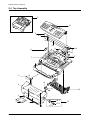
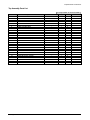
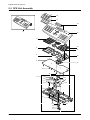
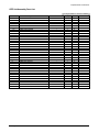
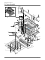
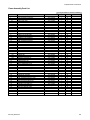
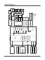
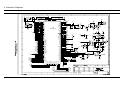
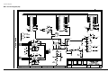
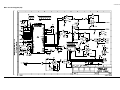
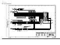
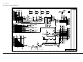
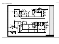
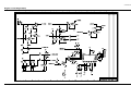
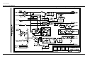
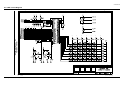
SAMSUNG FACSIMILE
Msys 730
SERVICE
Manual
SAMSUNG FACSIMILE
CONTENTS
1. Precautions
2. Specifications
3.
Disassembly and Reassembly
4. Troubleshooting
5. Exploded Views and Parts List
6. Block Diagram
7. Connection Diagram
ELECTRONICS
This service manual is also provided on the web,
the ITSELF system Samsung Electronics Co., Ltd.
“http://itself.sec.samsung.co.kr”
© Samsung Electronics Co.,Ltd. MAY 2002
Printed in Korea.
VERSION NO. : 1.00
CODE : JC-0073A
This manual is stated and
provided for service description.
All rights reserved. Any parts of the
information in this manual are prohibited
from free duplication, use or translation
without prior written approval except in
cases allowed by the Copyright Act.
Specifications are subject to change without
prior notice.
Samsung Electronics Digital Printing CS Group
Copyright (c) 2002. 5.
1. Precautions
Please read the following carefully to prevent any accidents and not to damage the unit during service.
1-1 Safety Precautions
1. Safety Precautions
There are some electric or machinery parts with safety
related property. If the parts replaced are different from
the original, the safety may not function. Even if the part
could allow higher voltage than that of the part used, do
not replace it and use a regular product clarified in specifications.
2. Be careful not to leave a switch, a cover or a safety device
out when reinstalling or assembling the product after
repair.
3. Replacing Precautions
Do not change or add parts as you like. You cannot benefit from such a remodeled product at your will during the
term of guarantee.
4. You must replace overheated or damaged parts or cords
with regular products. Please solve the problem causing
any damage or overheating and troubles beforehand.
LASER STATEMENT (LASERTURVALLISUUS)
WARNING : NEVER OPERATE AND SERVICE THE PRINTER
WITH THE PROTECTIVE COVER REMOVED
FROM LASER/SCANNER ASSEMBLY. THE
REFLECTIVE BEAM, ALTHOUGH INVISIBLE, CAN
DAMAGE YOUR EYES.
Class 1 laser product
Luokan 1 laserlaite
Klass 1 laser apparat
Allonpituus 770-795nm
Teho 0.3mW±0.03mW
CAUTION
INVISIBLE LASER RADIATION WHEN
THIS COVER OPEN. DO NOT OPEN
THIS COVER.
VORSICHT
UNSICHTBARE LASERSTRAHLUNG,
WENN ABDECKUNG GEOFFNET.
NIGHT DEM STRAHL AUSSETZEN.
ATTENTION
Especially mind the safety on the part with this
mark.
You must use regular parts described in specifications for the parts inflammable and where the current can be flown. Otherwise any hazard such as
an electric shock or a fire could occur.
REYONNEMENT LASER INVISIBLE EN CAS
D’OUVERTURE. EXPOSITION DANGERUSE AU
FAISCEAU.
ATTENZIONE RADIAZIONE LASER INVISIBLE IN CASO DI
APERTURA. EVITARE L’ESPOSIZONE LA FASCIO.
PRECAUCION REDIACION LASER INVISIBLE CUANDO SE
ABRE. EVITAR EXPONERSE AL RAYO.
CAUTION :
Avoid exposure to invisible laser radiation when the
development unit is not installed.
1-2 Precautions on Disassembly and Reassembly
Very careful precautions should be taken when replacing
parts. Before replacing, please check cables because you
cannot put the cables that you removed for replacing parts
into the proper place if you would not make sure of where
they were connected and in which condition.
7. When disassembling, assembling, also observe small
components are located in place.
8. If you uncover and turn the machine over to replace some
parts, toner or paper particles may contaminate the LSU
window. Protect the LSU window with clean paper.
Please do the following before disassembling
for a repair or replacement of parts.
1. Pull out paper cassette, printer cartridge installed.
Especially careful not to be scratched by the surface of
developer or not to expose them to light.
2. Turn the power switch off.
3. Take out the power plug, printer cable from the printer.
4. Use only the same type of part as original when replacing
parts.
5. Do not force to open or fasten plastic material components.
6. Be careful that small parts such as screws should not get
in the printer.
Samsung Electronics
Releasing Plastic Latches
Many of parts are held in
place with plastic latches.
The latches break easily :
release them carefully.
To remove such parts,
press the hook end of the
latch away from the part to
which it is latched.
1-1
Precautions
1-3 ESD Precautions
Certain semiconductor devices can be easily damaged by
static electricity. Such components are commonly called
“Electrostatically Sensitive (ES) Devices”, or ESDs.
Examples of typical ESDs are: integrated circuits, some field
effect transistors, and semiconductor “chip” components.
The techniques outlined below should be followed to help
reduce the incidence of component damage caused by static electricity.
CAUTION:
Be sure no power is applied to the chassis or circuit, and observe all other safety precautions.
1. Immediately before handling a semiconductor component or semiconductor-equipped assembly, drain off any
electrostatic charge on your body by touching a known
earth ground. Alternatively, employ a commercially available wrist strap device, which should be removed for your
personal safety reasons prior to applying power to the unit
under test.
2. After removing an electrical assembly equipped with
ESDs, place the assembly on a conductive surface, such
as aluminum or copper foil, or conductive foam, to prevent electrostatic charge buildup in the vicinity of the
assembly.
4. Use only an “anti-static” solder removal device. Some solder removal devices not classified as “anti-static” can
generate electrical charges sufficient to damage ESDs.
5. Do not use Freon-propelled chemicals. When sprayed,
these can generate electrical charges sufficient to damage ESDs.
6. Do not remove a replacement ESD from its protective
packaging until immediately before installing it. Most
replacement ESDs are packaged with all leads shorted
together by conductive foam, aluminum foil, or a comparable conductive material.
7. Immediately before removing the protective shorting
material from the leads of a replacement ESD, touch the
protective material to the chassis or circuit assembly into
which the device will be installed.
8. Maintain continuous electrical contact between the ESD
and the assembly into which it will be installed, until completely plugged or soldered into the circuit.
9. Minimize bodily motions when handling unpackaged
replacement ESDs. Normal motions, such as the brushing together of clothing fabric and lifting one’s foot from a
carpeted floor, can generate static electricity sufficient to
damage an ESD.
3. Use only a grounded tip soldering iron to solder or desolder ESDs.
1-2
Samsung Electronics
Precautions
1-4 Tools for Troubleshooting
The following tools are recommended for safe and smooth troubleshooting described in this service manual.
DVM(Digital Volt Meter)
Pinset
Standard : Indicates more than 3 digits.
Standard : For general home use, small type.
Electronic Scale
Cotton Swab
Standard : Equipment to check the weight of consumables(toner cartridge) . (The gram unit
can be measured.)
Standard : For general home use, for medical service.
Driver
Standard: "-" type, "+" type (M3 long, M3 short, M2
long, M2 short)
Cleaning Equipments a IPA(Isopropyl
Alcohol) dry cloth or a soft stuff neutral
detergent.
Note
Samsung Electronics
Mind your hands not to be touched when
you disassemble and reassemble PBA ASS'Y,
such as the main board, SMPS, HVPS.
1-3
2. Specification
2-1 Facsimile
Machine type
Desk Top
Applicable line
Public Switched Telephone Network (PSTN) or behind PABX
Compatibility
CCITT Group 3
Data coding
MH/MR/MMR
Modem speed
33600/31200/28800/26400/24000/21600/19200/16800/
14400/12000/9600/7200/4800/2400 bps
Transmission speed
Approx. 6 sec.(14.4K,ECM,4% Letter)
Effective scanning width
8.2 inches (208 mm)
Effective printing width
8.2 inches (208 mm : LTR)
Scanning method
Sheet-fed scanning using a Contact Image Sensor (CIS)
Memory
5 MByte
Halftone
256 levels
Printing speed
8 PPM (Letter size)
Automatic document feeder
50 pages (75g/m , 20lb : 0.09 ~ 0.10 mm thickness)
Documents size
Width
5.8 to 8.5 inches (148 to 216 mm)
Length
Single page : 5 to 59 inches (128 to 1,500 mm)
2
Multi pages : 8.3 to 11.7 inches (279 to 297 mm)
Weight
(thickness)
Single page : 12.5 to 32 lb (50 to 100g/m2) (0.07 to 0.15 mm)
20 pages: 12.5 to 28 lb (50 to 90g/m2) (0.07 to 0.13 mm), Uncoated paper
50 pages : 20 lb (75g/m2) (max 0.1 mm), Uncoated paper
One-touch dial :
Registration for 38 numbers
Speed dialing
Registration for 150 numbers
LCD :
16 characters x 2 lines
2-2 SCANNER
Scanning Method :
Resolution
Horizontal
Vertical
Gray Scale :
Scanning period :
Samsung Electronics
Sheet-fed scanning by CIS and feeding of the document by a
stepping motor
11.8 lines/mm (300 dpi)
STANDARD : 3.85 lines/mm (98 Lpi)
FINE : 7.7 lines/mm (196 Lpi)
SUPER FINE : 11.8 lines /mm (300 Lpi)
256 shades
STANDARD : 2.5 ms/line
FINE : 2.5 ms/line
SUPER FINE : 2.5 ms/line
2-1
Specification
2-3 Printer
Print Speed
Resolution
Source of Light
Print Method
Feed Method
Feed Reference
Paper Size
Paper Weight
Paper Capacity
Paper Stacker Capacity
Warming up Time
First Printing Time
Cassette Type
Length
Width
For MPF
For Manual
MPF
Manual Slot
Stand-By
Power Save Mode
Power Rating
Power Consumption
Max.
Stand-by
Avg.
Power Saving Consumption
Certification & Compliance
Acoustic Noise
Standby
Operating
Toner Cartridge
Expected Life Span
Operating Environment
Storage Environment
Weight
SET
SCF
External Dimension
Developer
Life Span
Developing
Charging
Density Adjustment
Toner Supply Method
New Developer Checkable
Transfer System
Fusing System
OZONE Emission
2-2
8 PPM (A4 Size, 5% Charcter Pattern) : At Copy Mode
600 X 600 DPI
Laser Diode(LSU)
Non-impact Electrophotography, Laser Beam
Multi-Purpose Feeder and Manual
Side Reference Loading
Normal Paper : A4,Letter,Legal,B5,Executive
A5 (for manual)
148 ~ 356mm
98 ~ 216mm
2
60 ~ 90g/m
2
60 ~120g/m
2
250 Sheets (based on 75g/m )
1 Sheet
2
Face up : 150 Sheets (75g/m ,20 lb)
About 20 sec
About 25 sec
About 40 sec
AC 110V ~127V ± 15% 50/60Hz ± 3Hz,
AC 220V ~ 240V ± 15% 50/60Hz ± 3Hz
210Wh
50Wh
13Wh
Sleeping Mode
FCC, cUL, CE, CB, IC CS-03
Less than 36dB
Less than 50dB
One-Cartridge type
100,000 Sheets
Temperature : 10 ~ 30°C , Humidity : 30 ~ 80%RH
Temperature : 0 ~ 35°C , Humidity : 20 ~ 95%RH
Net : 9 kg
Gross : 14.3 kg
Net : 4.8 kg Gross : 6.0 kg
386(W) X 405(D) x 270(H)mm
5% Pattern,Min. 6,000 Sheets
Non-magnetic Contact Developing
Conductive Roller Charging
Dark, Medium
Exchanging Toner Cartridge
YES
Pre-transfer By LED & Conductive Roller Transfer
Temperature & Pressure
Max. 0.1 PPM(8 Hours)
Samsung Electronics
Specification
2-4 Quality
Conditions
Paper
Environment
Print Quality
Image Density
Background
Uniformity
Fusing
Start Position
Skew
Orthogonality
Horizontal Scan
Special Paper Exception
Paper Jam
Paper Curl
Reliability
Fusing System
Insulation Resistance
Dielectric Strength
Ground Continuous
Voltage DIP
AC Impulse Noise
Leakage Current
Surge
OZONE Emission
Top Cover Open
Overcurrent Protect
Trouble Sensing
Overheat Sensing
Samsung Electronics
2
Normal Paper , 75g/m
Temperature : 20 ~ 25°C
Humidity : 40 ~ 60%
Min. 1.3
Min. 1.0(Temperature : 10 ~ 15°C) ,Samsung Paper
Max. 0.2
Max. 0.2(Including Continuous Print)
Min. 75% (All Black)
Top : 4.23mm ± 2, Side : 4mm ± 2
From Left
Top : Max. ± 1.5mm/200mm
Side : Max. ± 2.0mm/250mm
± 1.0mm
± 0.6mm/200mm
(Bowed Line Skew : Pattern 1)
Image Density : Min 1.0 (Envelope)
Fusing : Min. 70% (All Black)
(Envelope/OHP/Postcard)
2
Less than 1/1,000(75g/m Paper)
First : Less than 16mm (10 Sheets, 75g/m2 Paper)
After Cooling : Less than 16mm (10 Sheets, 75g/m2 Paper)
Less than 10 MΩ (at DC 500V)
AC 1000V (DC 1420V), 10mA
Less than 0.1Ω
Rated Voltage ± 15%
AC 1000V 10, 100, 200, 400, 1000ns
Rated Power
Less than 3.5mA
6 KV, 500A
Less than 0.1 ppm (8 Hours)
Isolating the input power of the LSU,
High Voltage Part, and Fuser
Fuse inside the Engine Controller
.The temperature doesn’t rise to the specific
temperature in the specific time.
.The temperature is too high.
240 ~ 250°C (The thermostat cuts off the Fuser from the
power.)
Thermistor Open Sensing : Without the initial temperature
change of the Fuser
2-3
Specification
2-5 SMPS (Switching Mode Power Supply)
Input (AC)
Output (DC)
AC Input Voltage
Minimum
Typical
Maximum
Max. AC Input Currents
Max. Inrush Current)
Line Regulation
Road Regulation
Ripple Noise
Over Current Protect
Over Voltage Protect
2-4
American
90V
120V
135V
3Amps
40 Ap-p (at 25°C)
24V ± 10%
12V ± 5%
-12V ± 5%
5V ± 5%
24V : Peak 500mVp-p
12V : Peak 500mVp-p
-12V : Peak 500mVp-p
5V : Peak 300mVp-p
24V : 2.7A ± 10% (by Circuit)
5V : 3A ± 10% (by Circuit)
24V : 33V
5V : 5.6V
Samsung Electronics
Disassembly and Reassembly
3. Disassembly and Reassembly
3-1 General Precautions on Disassembly
When you disassemble and reassemble components, you must use extreme caution. The close proximity of cables to
moving parts makes proper routing a must.
If components are removed, any cables disturbed by the procedure must be restored as close as possible to their original positions. Before removing any component from the machine, note the cable routing that will be affected.
Whenever servicing the machine, you must perform as follows:
1. Check to verify that documents are not stored in memory.
2. Be sure to remove the toner cartridge before you disassemble parts.
3. Unplug the power cord.
4. Use a flat and clean surface.
5. Replace only with authorized components.
6. Do not force plastic-material components.
7. Make sure all components are in their proper position.
3-2 Releasing Plastic Latches
Many of the parts are held in place with plastic latches. The latches break easily; release them carefully.
To remove such parts, press the hook end of the latch away from the part to which it is latched.
Samsung Electronics
3-1
Disassembly and Reassembly
3-3 White Roller
1. Open the OPE panel, then set the support-OPE to
the OPE panel.
2. Push the bushing on the both ends of the roller
slightly inward, then rotate it until it reaches the slot.
Then lift the roller out.
Bushing
Note: Check the roller for any dirt. If dirty, wipe it off with
soft cloth dampened with water. If the roller is heavily worn, replace it with a new one.
3-4 Transfer Roller
1. Open the front cover, and release one end of the
roller using a proper tool as shown in the square.
2. Pull the other end of the roller slightly inward, then lift
it up.
Transfer roller
3-2
Samsung Electronics
Disassembly and Reassembly
3-5 Rear Cover
1. Remove four screws, unplug one harness, then
remove the rear cover.
2. If you want to remove the dummy fan from the rear
cover, remove two screws and release two latches,
then take it out.
3-6 Left Side Cover
1. Before you remove the cover, you should remove:
– Rear cover (see page above)
2. Open the front cover, remove one screw, then
remove the left side cover.
Samsung Electronics
3-3
Disassembly and Reassembly
3-7 Right Side Cover
1. Before you remove the cover, you should remove:
4. Unplug the speaker harness from the main board,
then remove the right side cover.
– Rear cover (see page 3-3)
2. Open the front cover, and remove one screw.
5. If you remove the fan from the side cover, remove
two screws, then take it out.
3. Remove three screws, then pull the plate slightly
toward you to release the side cover.
When you reassemble
the fan, make sure
that the fan is placed
correctly.
3-4
Samsung Electronics
Disassembly and Reassembly
3-8 OPE Assembly
1. Before you remove the cover, you should remove:
– Rear cover (see page 3-3)
– Left/Right side covers (see page 3-3, 3-4)
4. To unlatch the OPE ass’y, spread the both ends of
the OPE ass’y shown in circles in the figure below,
then remove the OPE ass’y.
2. Open the OPE panel, then set the support-OPE to
the OPE panel.
3. From the right side of the main body, remove two
Spread the both ends of the OPE ass’y.
ground screws and unplug one OPE harness. .
Samsung Electronics
3-5
Disassembly and Reassembly
ADF Rubber on the OPE Ass’y
OPE PBA on the OPE Ass’y
1. Remove five screws, then remove the scan upper
frame.
1. Remove seven screws, release the plastic latches
securing the board, then turn the board upside down.
2. To unlatch the ADF rubber, push the plastic latches
on the ADF rubber from the bottom of the OPE ass’y.
Then remove the ADF rubber..
3-6
2. Remove a screw and release one of the latches
securing the LCD board, then remove the OPE
board with the LCD board.
Samsung Electronics
Disassembly and Reassembly
Lever Sensor on the OPE Ass’y
Pinch Spring on the OPE Ass’y
Squeeze the both ends of the lever sensor and lift it up.
Remove three screws securing the pinch spring then
take it out.
Pinch on the OPE Ass’y
Spring on the OPE Ass’y
Remove the pinch from the OPE ass’y.
Release one end of the spring and take it out from the
OPE ass’y.
Samsung Electronics
3-7
Disassembly and Reassembly
3-9 Top Assembly
1. Before you remove the cover, you should remove:
– Rear cover (see page 3-3)
– Left/Right side covers (see page 3-3, 3-4)
– OPE ass’y (see page 4-8)
2. Remove two screws and unplug two connectors from
the main board, then remove the Top ass’y pushing
in the direction of the arrows in order.
1
2
3
3-10 Scan Lower Frame
1. Before you remove the scan lower frame, you should
remove:
– Rear cover (see page 3-3)
– Left/Right side covers (see page 3-3, 3-4)
– Top Assembly (see page above)
2. Remove four screws and remove the scan lower
frame.
3-8
Samsung Electronics
Disassembly and Reassembly
Scan Motor on the Scan Lower Frame
CIS on the Scan Lower Frame
Remove two screws, and remove the scan motor.
Remove one screw, slide the CIS slightly in the direction
of arrow, then lift it up.
Rollers on the Scan Lower Frame
Remove rollers.
When you reassemble the CIS,
be careful for the direction of
this part.
Samsung Electronics
3-9
Disassembly and Reassembly
3-11 Main Cover and Front Cover
1. Before you remove the covers, you should remove:
4. Remove the left and right hinge shafts. Now the two
covers can be separated.
– Rear cover (see page 3-3)
– Left/Right side covers (see page 3-3, 3-4)
– OPE assembly (see page 3-5)
– Top assembly (see page 3-8)
– Scan lower frame (see page 3-8)
2. Remove two screws.
3. Remove shafts and springs connecting the two covers.
3-10
Samsung Electronics
Disassembly and Reassembly
3-12 Main Board
1. Before you remove the main board, you should
remove:
– Rear cover (see page 3-3)
– Right side cover (see page 3-4)
2. Unplug all connectors from the main board, then
remove the board.
3-13 LIU Board
1. Before you remove the LIU board, you should
remove:
– Rear cover (see page 3-3)
– Right side cover (see page 3-4)
2. Remove two screws, then unplug all connectors from
the LIU board, then remove the board.
Samsung Electronics
3-11
Disassembly and Reassembly
3-14 Socket Contact Assembly
1. Before you remove the assembly, you should
remove:
– Rear cover (see page 3-3)
– Right side cover (see page 3-4)
– LIU board (see page 3-11)
2. Remove two screws, and unplug one connector from
the main board, then remove the socket contact
ass’y.
3-15 LSU
1. Before you remove the LSU, you should remove:
– Rear cover (see page 3-3)
– Left/Right side covers (see page 3-3, 3-4)
– Top assembly (see page 3-8 )
2. Remove three screws, unplug two connectors, then
remove the LSU.
3-12
Samsung Electronics
Disassembly and Reassembly
3-16 Motor Assembly and Fan
1. Before you remove the motor assembly, you should
remove:
4. Remove a screw securing the fan and remove the
fan.
– Rear cover (see page 3-3)
– Left/Right side covers (see page 3-3, 3-4)
– Top assembly (see page 3-8)
2. Remove two screws securing the fan.
5. Remove three screws from the motor assembly.
3. Remove five screws, unplug two connectors, then
remove the motor assembly.
6. Remove two screws from the motor bracket and
remove the motor.
Samsung Electronics
3-13
Disassembly and Reassembly
3-17 Fuser
1. Before you remove the fuser, you should remove:
– Rear cover (see page 3-3)
2. Remove the exit actuator and unplug two connectors.
3. Remove four screws, then remove the fuser.
3-14
Samsung Electronics
Disassembly and Reassembly
Thermostat on the Fuser
Thermistor on the Fuser
Remove two screws securing the thermostat and take it
out.
1. Remove four screws and remove the upper cover.
2. Remove the heat roller.
3. Remove two screws securing the thermistor, then
take it out.
Samsung Electronics
3-15
Disassembly and Reassembly
Halogen Lamp on the Fuser
Roller on the Fuser
1. Release the connector cable from its recessed channel.
1. Remove four screws and remove the upper cover.
2. Remove the roller.
2. Remove one screw and remove the halogen lamp.
Note: When you reassemble the lamp, make sure that
the halogen lamp is inserted in place.
3-16
Samsung Electronics
Disassembly and Reassembly
3-18 Engine Board and Others
1. Before you remove the engine board, you should
remove:
4. Remove seven screws, and release the latch securing the PCU shield.
– Rear cover (see page 3-3)
– Left/Right side covers (see page 3-3, 3-4)
– Top assembly (see page 3-8)
2. Remove four screws and remove the right and left
base brackets.
5. Unplug all connectors and remove PCU shield.
3. Remove two screws and remove the ICU ground.
Samsung Electronics
3-17
Disassembly and Reassembly
HV Terminals
Remove HV terminals. When you reassemble the terminals, make sure that the terminals are inserted in place.
SCF Connector
Remove two screws and remove the connector.
Transfer Guide
Cover Open Sensor
Remove five screws and remove the transfer guide.
Remove the spring and remove the sensor.
3-18
Samsung Electronics
Disassembly and Reassembly
Pick-up Sensor
Erase Lamp
Squeeze both ends of the sensor and lift it up.
Remove two screws, unplug one connector, then
remove the erase lamp.
Transfer Roller Bushing
Push them downward to be released.
Samsung Electronics
3-19
Disassembly and Reassembly
3-19 Pick-up Assembly
1. Remove two screws and remove the right
base bracket.
3. Remove the pick-up rubber.
Pull it up to
remove the rub-
2. Remove three screws and remove
Pick-up assembly.
3-20
Samsung Electronics
4. Troubleshooting
4-1 Preventative Maintenance
The cycle period outlined below is a general guideline for maintenance. The example list is for an average usage of 50 transmitted and received documents per day. Environmental conditions and actual use will vary these factors. The cycle period
given below is for reference only.
COMPONENT
SCANNER
CLEANING CYCLE
ADF Rubber
6 Months
10,000 Pages
ADF Roller
1 Year
20,000 Pages
Drive Roller
1 Year
50,000 Pages
White Roller
6 Months
50,000 Pages
CIS
6 Months
Cartridge
PRINTER
REPLACEMENT CYCLE
SOLUTION
6,000 Pages
Pickup Roller
1 Year
50,000 Pages
Feed Roller
1 Year
50,000 Pages
Transfer Roller
50,000 Pages
Fuser
30,000 Pages
4-2 Diagnostics
This section describes methods and procedures to isolate the cause of a malfunction in the machine. This machine displays diagnostic information on the LCD. In addition, it can perform a series of tests that allow the machine to observe individual machine
functions.
4-2-1 Error Messages
Error Message
Description
Solution
RETRY REDIAL?
The machine is waiting the programmed
interval to automatically redial.
You can press START to immediately
redial, or STOP to cancel the redial
operation.
COMM. ERROR
A problem with the facsimile
communications has occurred.
Try again.
DOCUMENT JAM
Loaded document has Jammed
in the feeder
Clear the document Jam.
Samsung Electronics
4-1
Troubleshooting
Error Message
Description
Solution
DOOR OPEN OR NO
TONER CARTRIDGE
The front cover is not securely latched.
Replace the cover firmly until it clicks in place.
No toner cartridge in the fax machine.
The machine stops.
Install the toner cartridge in place properly.
GROUP NOT AVAILABLE
You have tried to select a group location where only
a single location number can be used, such as
when adding locations for a multi-dial operation.
Try again, check location for group.
LINE ERROR
Your unit cannot connect with the remote machine,
or has lost contact because of a problem on the
phone line.
Try again. If failure persists, wait an hour or so
for the line to clear then try again.
LOAD DOCUMENT
You have attempted to set up a sending operation
with no document loaded.
Load a document and try again.
MEMORY FULL
The memory has become full.
Either delete unnecessary documents, or
retransmit after more memory becomes available, or split the transmission into more than
one operation.
NO ANSWER
The remote machine was not answered after all the
redial attempts.
Try again.
Make sure the remote machine is OK.
NO. NOT ASSIGNED
The one-touch or speed dial location you tried to
use has no number assigned to it.
Dial the number manually with the keypad, or
assign the number.
NO PAPER
The recording paper has run out. The printer system stops.
Load the recording paper in the paper feeder.
OVERHEAT
The printer part has overheated.
Your unit will automatically return to the standby mode when it cools down to normal operating temperature. If failure persists, call service.
PAPER JAM 0
Recording paper has jammed in paper feeding
area.
Press STOP and clear the jam.
PAPER JAM 1
Recording paper has jammed inside the unit.
Clear the jam.
4-2
Samsung Electronics
Troubleshooting
Error Message
Description
Solution
PAPER JAM 2
The jammed paper still remains inside the unit.
Clear the jam.
POLL CODE ERROR
When setting up to poll another fax machine, you
have used an incorrect poll code.
Enter the correct poll code.
POLLING ERROR
The remote fax machine you want to poll is not
ready to respond to your poll.
The remote operator should know in advance
that you are polling and have their fax unit
loaded with the original document.
POWER FAILURE
A power failure has occurred.
If there has been documents stored in memory.
Power failure report will be printed automatically
when the power is restored.
PLEASE WAIT
The machine is warming up and is off line.
Wait until the machine is on-line.
Samsung Electronics
4-3
Troubleshooting
4-2-2 Test Mode
Switch Test
The test mode is used to test certain functions of the
machine. The available tests are:
This test checks the operation of the LCD display and the
LED indicators that interface the switches on the operation
panel.
•User mode : Clean drum ’ Adjust shading ’ Notify toner
low
•Tech mode : Switch Test ’ Modem Test ’ Memory Test ’
ROM Test ’ DRAM Test ’ Pattern Test
Modem Test
This test causes the machine to generate a particular frequency to verify the operation of the modem control circuits
and the modem.
To enter the Test Mode:
Memory Test
1. Get into the Tech mode by pressing Menu, #, 1, 9, 3, 4.
2. In Tech mode, press Menu, and ‘Maintenance’ on the
one-touch keypad.
3. Scroll to the options by pressing or repeatedly until
you find the one you want.
4. Press Enter to initiate the test mode.
Cleaning DRUM
This procedure removes excess toner on the OPC drum.
1. Make sure that paper is loaded in the automatic feeder.
2. Press Menu, and Self-Test on the one-touch
keypad.
3. Press Enter. The machine automatically pulls in a sheet of
paper, and prints out. The toner particles on the OPC
drum surface is fixed to the paper.
ADJUST Shading
This procedure is needed to set (make) a new shading reference value. The reference value is preset at factory.
However, when the CIS or the main board is replaced with
new one, the reference value must be set again.
Load the white, letter-sized paper into the feeder and perform the test mode (MENU+ONE-TOUCH ‘SYSTEM
SETUP’). Follow the next steps as instructed through the
LCD window. After the shading value is newly set, the shading value pattern is automatically printed. The shading value
pattern shows the value of the white reference level of the
Contact Image Sensor. Check for the waveform in the pattern. It is best when the wave form is level. If there are many
points sharply broken, perform the Make shading procedure
several times until you get a level waveform.
4-4
This test is used for checking the Random Access Memory
(RAM) on the main PBA. If all memory is working normally,
the LCD shows TESTING OK!.
When this testing is carried out, any picture data
stored in memory is erased.
ROM Test
This test mode will display and check the current ROM level
in your machine.
FLASH VER. : 1.0.0 V
ENGINE VER : 1.0.0 V
DRAM TEST
This test checks the DRAM memory status and shows if it is
functioning properly
Pattern Test
1. Pattern Test ?
2. Pattern 1 ? - There are 4 different pattern tests.
Scroll to the options by pressing or
repeatedly until you find the one you want.
3. Press START key.
4. Key in the number of pages.
5. Press START key.
Notify Toner Low
With this feature enabled, when the toner becomes low, the
toner low information will be sent to ta specified contact point,
for example, the service company. After you access this
menu, select ON, and when the LCD prompts, enter the
name and the number of the contact point, the customer’s
fax number, the model name, and the serial number.
Samsung Electronics
Troubleshooting
4-2-3 Maintenance List
A number of reports can be printed from the fax machine
within the test mode. The protocol list and memory dump list
all contain detailed information which may be required when
contacting technical support.
2. In Tech mode, press Menu, and ‘Tx. Confirm’ on the
one-touch keypad.
3. Press or repeatedly until you find the Protocol Dump
List. When you find ‘PROTOCOL REPORT?’, press
ENTER. SAMPLE OF A PROTOCOL DUMP LIST
To printout the protocol and memory dump lists:
1. Get into the Tech mode by pressing Menu, #, 1, 9, 3, 4.
Facsimile Information Field
data described in hexdecmal code
Sending/Receiving
Name of signal
(Facsimile Control Field)
PROTOCOL DUMP LIST
FIF data described
in ASCII code
OCT-20-1999 06:35
S/R
FCF
FIF DATA
ASCII
S
S
S
S
S
S
R
R
S
R
R
S
R
S
S
NSF
CSI
DIS
NSF
CSI
DIS
TSI
DCS
FTT
TSI
DCS
CFR
MPS
MCF
DCN
61006820003380140200001302090018010000
2020202020202020202020202O20202020202020
00000000 01110111 00010111 00100010
61005020003380140200001302090018010000
202020202020202020202022O202020220202020
00000000 01110111 00010111 00100010
2020202020202020202020202O20202020202020
00000000 01100001 00010101 00000000
2020202020202020202020202O20202020202020
00000000 01100001 00010101 00000000
< SAMPLE OF A PROTOCOL DUMP LIST >
4-2-4 Engine Test
The Engine test mode is used to check the operation of the
components related the printer engine. In this mode, the
tests are classified into the five numbers. The available tests
are:
0 : Motor Start/Stop, Solenoid On/Off, Qlamp On/Off, Motor
Fan On/Off, Rear Fan On/Off
1 : LSUmotor On/Off, LSUoperation On/Off, LD On/Off
2 : Feed sensor On/Off, Exit sensor On/Off, Paper sensor
On/Off, Cover sensor On/Off
3 : MHV On/Off, Devbias On/Off
4 : SCF Motor On/Off, SCF Solenoid On/Off, SCF Paper
Empty On/Off, SCF Installed
5 : THV EN On/Off,THV On/Off,THV NEG On/Off
Samsung Electronics
To enter the Engine test mode:
1. Press Menu, #, 1, 9, 3, 1 in sequence.
2. When you see ‘ENGINE TEST?’, press Start ‘ENGINE
TEST NO>O-5‘ appears in LCD window.
3. Enter the number you want.
4. Scroll to the options by pressing
you find the one you want.
or
repeatedly until
5. Press Start to begin the test.
6. After the engine test is finished, press Stop to exit the
Engine test mode.
4-5
Troubleshooting
4-3 Print Quality
Error Status
Check
Solution
Vertical black line and band
1. Bad blade of Toner cartridge
2. LSU
1. Change Toner cartridge
2. Replace LSU
Vertical white line
1. LSU window contamination
2. Toner cartridge
1. Clean LSU window
2. If not LSU, change Toner cartridge
No image
1.
2.
3.
4.
5.
1. Removing seal tipe
2. Measure the resistance between frame
ground and the ground spring attached
frame. Confirm stable ground. Unless
bad ground, detach cabinet, check
where is bad point
3.Adjust LSU or replace it
4. Normal Dev bias = -300V
5. Shake toner cartridge and print.If a
liitke good, toner is empty
Light image
Dark image
Background
Ghost
4-6
Seal tape is removed?
GND OPC is well grounded?
LSU running well?
Biss voltage is normal?
Lower toner?
1.
2.
3.
4.
5.
6.
Check seal tape removing
LSU light power normal?
Enough toner?
High charger voltage?
Lower bias voltage
Contamination of high voltage contact
7. Transfer volatge and roller
1. Check and remove tape
2. LSU light power check is difficult.
Compare with new one and check.
3. Check toner and developer counter
4~5. Measure all high voltage output
6. Leakage toner cause bad contact and
increase contact resistance. Clean
contaminated area.
1. LSU light power normal?
2. Bias voltage output is high?
3. Video data is always supplied?
1. Check the rated level and replace
2. Set to power rating
3. Replace defected board
1. High voltage output is normal?
2. C/R of Toner cartridge is contaminated?
1. Adjust to the rated status
2. Replace Toner cartridge
1. High voltage output
2. Bad high voltage contact
1. Check every high voltage
2. Clean the inside machine or replace
toner cartridge
Samsung Electronics
Troubleshooting
Error Status
Check
Solution
Stains on back of
paper
1. Contamination of transfer roller
2. Stains of paper path
3. Pressure roller’s contamination
1. Clean the transfer roller with vaccum
cleaner
2. Clean the area of paper path with cloth
or air cleaner.
3. Remove fuser and replace it
Poor Fusing
1. Use recommended paper?
2. Check fusing temperature
3. The machine was under the low
temperature for a long time?
1. Should use recommended paper
2. Check engine board.
If you have not thermometer, measure
the thermistor voltage to CPU, If
2.98V±5% in printing CPU works well.
Then, disassemble fuser and check
the thermistor contact and thermistor.
3. Re-check after putting the machine in
the warm place for certain period.
Partial blank image
(not periodic)
1. Toner is low?
2. The toner cartridge is out of position?
1. Replace Toner cartridge
2. Checkand adjust
Partial blank image
(periodic)
1. Develope roller scar or particle
2. Scar or particle (94 mm)
3. Transfer roller scar or particle
(47 mm)
1~2. Replace toner cartridge
3. Replace transfer roller
1. Charge roller’s pressure force
unbalance
2. Dev. roller and OPC or Dev. roller
and blade’s pressure force unbalance
3. Transfer roller’s pressure force
unbalance of each side
1~2. Change toner cartridge
3. Check left and right spring of transfer
roller and the spring pressing the
developer inside the machine
1.
2.
3.
4.
1. Clean each contact and check good
contact
2. Clean charge roller
3. Replace fuser unit
4. Check engine B’d
Different image density
(left and right)
Horizonral band
Samsung Electronics
Unstable high voltage contact
Charge roller’s contamination
Contamination of heat roller
Malfunction of LSU
4-7
Troubleshooting
4-8
No
Roller
Abnormal image period
Kind of abnormal image
1
OPC Drum
94.2mm
White spot
2
Charge Roller
37.7mm
Black spot
3
Supply Roller
31mm
Horizontal density band
4
Develope Roller
46.7mm
Horizontal density band
5
Transfer Roller
47.1mm
Black side contamination/transfer fault
6
Heat Roller
56.4mm
Black spot, White spot
7
Pressure Roller
56.5mm
Black side contamination
Samsung Electronics
Troubleshooting
No Image
No image?
A on
next page
NO
YES
Take out the cartridge
and prepare the tester
for electronic connection
Is the OPC
terminal of machine
is well-connected
to Frame?
NO
Repair or replace the GND
terminal
YES
Does the
video data line to
LSU transit to High/Low
when printing?
NO
Check the path between
video controller, engine board.
Repair or replace the defective
component or board
YES
The mirror in LSU might be
misplaced so the light path to the
OPC deviates ->Repait or replace
LSU or remove any deffective
matters in the machine
Samsung Electronics
4-9
Troubleshooting
A
Trnasfer
voltage OK? (on the
transfer roller
shaft)
NO
YES
Are the
connection terminal
and connection
correct?
NO
Repair or replace terminal
YES
Replace Engine B’d or repair defective component
Developing
(-300V) and supplying
(-500V) voltage
are OK?
NO
Is the connection
terminal OK?
NO
Repair or replace terminal
YES
YES
Replace Engine B’d or repair
defective component
Sealing tape
is removed from the
cartridge?
NO
Remove the tape
YES
Does the
counter indicate over
the toner’s guarranty
life
YES
NO
Transfer roller might be out of its location
-> Locate the roller into its place
This could occurrs when he power of LSU is low or
the density is low due to the obstacles on the window
-> Replace LSU or clean the window
Replace the toner cartridge
4-10
Samsung Electronics
Troubleshooting
All Black
All black in
printing area?
NO
YES
Does the
video data line to LSU
transit to High/Low when
printing?
NO
Check the path among video
controller, engine board,
LSU for the shortage or open
-> Repair or replace the boards
YES
Replace LSU
Is transfer
voltage supplied
from Engine B’d?
NO
Repair or replace Engine B’d
YES
Is the
Hsync/ signal received
in LSU?
NO
Replace LSU
YES
Transfer part’s contact
is bad -> Repair or
replace toner cartridge
Samsung Electronics
4-11
Troubleshooting
Vertical White Line (Band)
White line
missing definitely?
YES
Dirt of dust stuck onto the
window of internal lens of LSU
-> Clean it or replace LSU
Preventive obstacles through
the path between OPC of
developer and LSU prevent the
path -> Remove the obstacles
4-12
NO
Check if the
printout is still has the
NO
same problem even right after
passed through the
transfer roller
YES
The ribs in fuser or toner on the
roller may invoke the image
problem -> Replace the fuser
cover or the defective part
The image is originally black or the
black part is far close to the top
-> Use the pattern which has the
image below bigger than 10mm
from the top
Toner material might be stuck to
blade in the developer inside and it
prevents toner supply -> Replace
the developer
Check both if the toner cartridge’s
counter is over its guaranty and
amount of the toner material
-> Replace the toner cartridge
Samsung Electronics
Troubleshooting
Dark Image
NO
Dark selected
via RCP?
YES
Change to
Normal and test
Same at Normal?
NO
END
YES
Works cor
with -300V of Bias
voltage?
NO
Repair or replace the defective
component
YES
Works
correctly after
replaced LSU?
NO
Toner over supply due to the
adjustment fault of metering
blade in developer
-> Replace developer
YES
The power of LSU is set
high or internal problem
-> Replace LSU or adjust
voluem
Samsung Electronics
4-13
Troubleshooting
Background
Recommended
paper used?
NO
Print 20 to 30 pages using
the recommended paper
YES
- Adjust voltage or
replace Engine B’d
- Repair or replace
after
checking the
terminals’ contacts
NO
Transfer,
charge and developing
voltage are OK?
YES
NO
Same problem
occurs?
END
YES
Operating/
storage atmosphere is
too high temperature
/humidity?
YES
Solve the problem under
the recommended condition
(10-32 degree Centigrade)
NO
Dirt or
dust around the
charge roller?
NO
Replace the
toner cartridge
YES
Clean the charge roller
or replace step-up device
/terminal after check
Check Terminals or contacts and ’Guide-Deve Spring’
are misplaced
-> Repair or replace transfer roller etc.
NO
Work OK?
YES
Internal blade or
suppying part of the
developer is defective
-> Replace the toner
cartridge
4-14
Samsung Electronics
Troubleshooting
Ghost
Is it regular
interval of 94mm?
NO
YES
Is it regular
interval of 46mm?
Is it regular
interval of 47mm?
(as transfer roller
interval)
NO
YES
YES
A specific part of the transfer
roller has ruined or its
resistance value is changed
-> Replace transfer roller
Transfer roller cannot force
regularly due to the gears
eccentricity of transfer roller
-> Replace the defective
component
Check HVPS
contacts and
HVPS’s selfoutput
-> If failed,
repair/replace
Engine B’d
NO
Developing
/suppying voltage
normal? (-300V/
-500V)
Transfer
voltage is set to
standard?
YES
YES
Irregularity of NIP
between rollers in
developer
-> Replace developer
Bias voltage
is OK? (-300V)
NO
NO
- Repair or replaceEngine B’d
- Check and Repair or
replace the terminal
contacts
Adjust the Bias
voltage or replace
Engine B’d
YES
Operating/storage
temperature is too low or
not recommended
paper used?
NO
There may be a problem in toner
layer control in toner cartridge
-> Replace the developer
YES
Use the machine with
recommended paper and
at condition
Samsung Electronics
4-15
Troubleshooting
Black Dot
Is it regular
interval of 38mm?
YES
The problem occured
since the obstacles
stuck to charge roller
-> Replace developer
and C/R
4-16
NO
When taking
out the cartridge,
toner leaks?
YES
Toner leaks and toner
material dropped onto
the paper -> Replace the
developer
NO
Bad image
removes by
scratching?
YES
NO
The problem
randomly occured
due to the toner
fallen -> Clean the
machine
Check toner is stuck onto
the P/R or H/R in fuser
-> Clean it or replace
Samsung Electronics
Troubleshooting
Horizontal Band
Black band?
NO
Black band
is far about 10mm from
white band?
NO
YES
The OPC is damaged under the
direct sunlight for around 5
minutes -> If the same problem
persists in 10 hours, replace
the developer
Problem of internal
contacts in OPC
-> Replace developer
The black
band has regular
interval?
NO
This occurs when no
Hsync/ at LSU
-> Replace LSU
NO
Does it appear
at every 56.1mm at
specific place?
YES
94mm interval?
YES
The OPC is damaged due to
the irregular transfer voltage
of HVPS
-> Repair/replace Engine B’d
-> If the same problem persists,
replace the developer
Samsung Electronics
YES
NO
Problems of terminal contact,
transfer voltage supplying,
and transfer roller’s due to the
charge roller is ruined (38mm)
-> Repair/replace Engine B’d,
developer
Heat roller is ruined
-> Replace the roller
4-17
Troubleshooting
Irregular Density
OK after
taking out and
rocking the toner
cartridge?
YES
NO
When gray
pattern printing,
irregular density
persists?
NO
YES
transfer/
charge/developing
voltage drops while
printing?
YES
NO
Defective agitator in
the toner supplying part
of developer
->Replace the developer
Check if the ’guide deve
spring’ works OK and
repair/repalce
Check high voltage
output and repair/
replace terminals,
Engine B’d
It is over the guaranty
life of toner cartridge
(Check the counter
and replace it)
Bad images
NO
aroung the no image
area?
Irregualrity of toner
suppy from developer
-> Repalce developer
YES
Light distortion due to
the mirror ruined or
LSU’s diffused reflection
-> Replace LSU
4-18
Samsung Electronics
Troubleshooting
White Spot
Is it regular
interval of 94mm?
YES
Obstacles stuck on OPC’s
surface
-> Clean the OPC and
machine or replace
developer
NO
Transfer
voltage is normal?
NO
Too high voltage supplied
due to the setting error of
transfer voltage
-> Adjust/replace Engine B’d
YES
D/R in developing unit has
the defect
-> Replace the developer
When putting in/out the
developer, scratch is made
-> Replace the developer
Samsung Electronics
4-19
Troubleshooting
Poor Fusing Grade
After printing
NO
completed, any error
related fuser?
YES
Both ends
of thermostat
open?
The machine
placed under the
severe low tempera
ture for a long
time?
YES
NO
NO
While printing,
the voltage of pin 5
of U5 on engine
board is about
2.7V?
NO
Thermistor’s
contact is OK?
NO
YES
YES
Re-assemble
thermistor
Place the machine
at normal
temperature and
re-test
YES
Replace thermostat
and re-test
Open the top
cover. When black
printing, is the fuser NIP
width is 3.03.5mm?
NO
Check if the hardness of
P/R, and spring force is OK?
(hardness: 24 degree,
spring’s force: 3 Kg)
YES
Replace the contol
component on engine
board
Check any contact
problem in thermistor
and repair
4-20
The paper used is too
thick or contains too
much cotton in it
-> Re-test with the
recommended paper
Samsung Electronics
Troubleshooting
4-4 Malfunction
Error Status
Check
Solution
No power
1. Check power is supplying
2. Check fuse F1 open
1. If supplying power differs from machine’s
power rating, replace the machine.
2. Replace it.
Fuser Error
1. Thermostat open
2. AC wire open
3. Thermistor wire open
4. Engine Controller
1. Detach AC connector and measure the resistane between pin 1 and 2. If it is megohm,
thermostat is open, Replace it.
2. Check bad connector contact or wire is cut.
3. Check thermistor wire and its connection.
4. Replace Engine board
Cover open
1. When close Top cover, check the
lever is pressed
2. Micro switch’s contact
3. CPU and related circuit
1. Open top cover and press the lever with pen. If
Controller detects cover close, there is some
mechanical trouble in top cover and lever’s
assembly. If not so there is electrical problem.
Jam 0
Check where Jam 0 happens
1. Paper is not picked up
2. Paper is located in feed sensor
3. Happened when inserting specific
papers such as envelope into the
MPF (Multipurpose Paper Feeder)?
4. Happened when inserting specific
papers such as envelope into the
Manual Feeder?
5. Is the Stacker Extender is folded out?
6. Does not the Guide Adjust distort the
papers
1. Check whether solenoid is working or not by
using Engine test mode #0 (Acoustic judgement)
2. Check feed sensor malfunction.
Check if it is misplaced with paper width sensor.
3. Re-try inserting a fewer papers.
•fan the papers and align
•take out the loaded papers and insert
them reverse direction
4. Take out the loaded papers and insert them
reverse direction
•inserted papers as recommended for
Manual Feeding?
•When loading, tap the papers until paper
detect sensor senses loading
5. When using long papers, use the Stacker
Extender
6. Adjust Guide to fit the paper width
Jam 1
Paper is stopped in just after of fuser
unit.
1. It is mostly resulted from double feeding.
Check paper is well stocked in feeder.
2. Check feed actuator position and actuator’s
operating. There may be stiff movind or double
reflection. If not so, check the operation of feed
sensor by Engine test mode #2.
3. Check exit lever operation. Remore jam and
check actuator moving by hand. If actuator is
too stiff, paper is wrapped around the heat
roller. Remove obstacles or replace.
Samsung Electronics
4-21
Troubleshooting
Error Status
Check
Solution
Jam 2
Check where Jam 2 happens
1. Paper is curled and cannot exit.
2. Paper is curled in the exit cover?.
1. Remove paper using pinset or some tool and
watch if separate claws have any trouble.
Clean around fuser.
2. Check locking works wells. Watch whether the
ribs of exit cover hace any burr or resisitive
edge. If they do, remove obstacles or replace.
Jam 2 at face-up
tray
1. Tried to print and stack pages which
are not allowed for specific paper
type?
2. Does the too thin paper, which
passed through the fuser, touch the
Cover Fornt?
1. When using the thick paper such as envelope,
card stock, label and OHP, one-sheet printing
is recommended
2. To use thin paper, face-down is recommended
Clutch error
1. Check the spring of solenoid
2. Check the armature assembly/cushion
3. Electrical check
1. Check whether the spring is expanded or not.
2. Check armature is well installed. It may be
unstable assemble.
High voltage error
1. Check the terminal output voltage
2. Check HVPS
1. Remove the Toner cartridge and open the
cover and press cover open switch lever and
measure the voltage with high voltage probe
and sending printing data. If the voltage is normal, change the toner cartridge.
2. Check HV of in Engine B’d and change it.
Feeding obstacles
1. Does the black film in MPF prevent
the paper loading?
2. Does the Plate-knockup prevent the
paper loading?
Skew
Is the Guide adjust set to the paper
width?
1. Re-insert the film neatly into the front. When
inserting it, the Plate-knockup needs to be
aligned to the front.
2. Turn the power off and on. Open and close the
Top cover to return to the original state.
Fit the paper width using the Guide adjust.
4-22
Samsung Electronics
Troubleshooting
Error Status
Check
Solution
Stacking
1. Took out the Stacker extender to support long papers?
2. Stacked too many papers more than
Stacker can hold?
3. Face-up stacker does not neatly
stack the papers and stack not in
order.
1. Use extender as per the paper length.
2. The Face-up stacker normally can hold 150
2
pages when using 75g/m , however, stacking
capacity can be lowered depending on the type
of papers.
Engine Error
1. Check CBF Harness-5P/6P.
(HVPS B’D to LSU)
2. Check CBF Harness-24P.
(ENGINE B’D to HVPS B’D)
3. Check CBF Harness-20P.
(ENGINE B’D to JOINT B’D)
Refer to troubleshooting “ENGINE ERROR”.
Samsung Electronics
4-23
Troubleshooting
No Power (LCD NO display)
Plug in the
power cord?
NO
Check the voltage first and plug
the power cord
YES
The power
NO
voltage supplying is
the same as
rating?
Supply the power as the rating
YES
The fan
revolves when
powered on?
NO
Connections
NO
on board are OK?
YES
YES
The On-Line
key is being pressed
or shortage on
the panel
board?
YES
NO
The connection
error between
controller board
and panel board
or malfunction
of boards.
-> Replace the
boards
Fuse of SMPS
if open?
4-24
NO
Replace the fuse
YES
Shortage
between 5V and
GND, or between
24V and
GND?
YES
Repair/replace the
OPE board
Re-connect firmly
and re-test
Remove the shortage
or replace the board
NO
Toner cartridge
is in the set?
NO
Put in the
cartridge
YES
Detect failure due to the
board which detects top
cover open or switch error
-> Replace the board or switch
Samsung Electronics
Troubleshooting
Fuser Error
Measure the resistance
at the both ends of AC
Line with covers open
Less than 10W?
NO
Thermostat is open due to the heat etc.
-> Replace the thermostat
YES
Remove the Rear covers
AC is being supplied?
NO
Re-assemble the top
cover and close it
Check the voltage of pin#6
of U5,if it is about 2.3
it’s OK if not check the
CON4 in Power B’d
YES
The voltage
of pin #5 of U5
on the engine board
is about 2.7V when
printing?
NO
Thermistor, connecting point or engine
board defect -> Repair/replace the
component/board
YES
END
Samsung Electronics
4-25
Troubleshooting
Paper Jam (Mis-feeding)
Sounds the
solenoid on when starts
print?
NO
The engine board defected
-> Replace board
The solenoid defected
-> Replace it
YES
Does the
paper move?
The pick-up unit is
assembled wrong
-> Re-assemble or replace
the unit
NO
YES
Does the
paper move more than NO
100mm?
Too many
papers in the
feeder?
YES
YES
Feeder
sensor and paper NO
width detect sensor
are assembled
reverse?
The sensor and
joint boards defected
-> Repair/replace
Reduce the amount
and re-test
YES
Switch them
NO
Paper guides
fit the paper width?
Take out the paper
and re-insert
YES
Paper end curled?
YES
Use the recommended
and quality paper
4-26
NO
Does the
NO
extender pulled out?
Pull out the
extender
YES
<Recommendation>
Use the MPF for the thick
paper such as envelope
and cardstock
Samsung Electronics
Troubleshooting
Paper Jam (Jam1)
Paper
NO
stopped before
the OPC?
Paper
NO
stopped before
the fuser?
YES
YES
The
actuator of
NO
paper exit sensor
works OK?
Check the actuator exists and its
operation and around the engine board
-> Replace
YES
Check the LSU and
if it has the defect
replace it
Is the paper
rolled around the
presseure
roller?
NO
Feeds
NO
multiple pages?
YES
YES
Remove the fuser, remove
the paper and replace the
pressure roller, if necessary
Severe skew
when feeding?
NO
YES
Adjust the paper guides to fit the
paper width
The force of springs pressing the
developer is weak
-> Check guide-DEVE
Check the roller
and ribs of fuser
are in place, and
remove burrs, if
any
-> Remove the
factors of jam
Remove any factors
The paper
came out through
between fuser and
developer?
NO
Check the input path
to the fuser (such as
mis-assembly)
YES
Too thin
or sensitive paper to
static electricity?
NO
Check guide transfer
is grounded Check
the shutter prevents
feeding
YES
Use the recommended
paper
Samsung Electronics
4-27
5. Exploded Views and Parts List
The material codes mentioned in the manual are subject to change without prior notice.
For the latest exact information, see ITSELF SYSTEM. (http://itself.sec.samsung.co.kr)
5-1. Main Assembly . . . . . . . . . . . . . . . . . . . . . . . . . . . . . . . . . . . . . . . . . .page(5-2)
5-2. Top Assembly . . . . . . . . . . . . . . . . . . . . . . . . . . . . . . . . . . . . . . . . . . .page(5-4)
5-3. OPE Unit Assembly . . . . . . . . . . . . . . . . . . . . . . . . . . . . . . . . . . . . . .page(5-6)
5-4. Frame Assembly . . . . . . . . . . . . . . . . . . . . . . . . . . . . . . . . . . . . . . . . .page(5-8)
5-5. Fuser Assembly . . . . . . . . . . . . . . . . . . . . . . . . . . . . . . . . . . . . . . . .page(5-10)
5-6. TX Unit Assembly . . . . . . . . . . . . . . . . . . . . . . . . . . . . . . . . . . . . . . .page(5-12)
5-7. Pick Up Assembly . . . . . . . . . . . . . . . . . . . . . . . . . . . . . . . . . . . . . . .page(5-14)
5-8. Motor Assembly . . . . . . . . . . . . . . . . . . . . . . . . . . . . . . . . . . . . . . . .page(5-16)
5-9. PCU Assembly . . . . . . . . . . . . . . . . . . . . . . . . . . . . . . . . . . . . . . . . .page(5-17)
5-10. Cassette Assembly . . . . . . . . . . . . . . . . . . . . . . . . . . . . . . . . . . . . .page(5-18)
5-11. Second Cassette Frame Assembly . . . . . . . . . . . . . . . . . . . . . . . .page(5-20)
Samsung Electronics
5-1
Exploded Views and Parts List
5-1 Main Assembly
23
22-2
22
10
11
11-4
22-1
S2
11-3
11-2
11-1
12-3 12-2
12-1
12-4
9
12
S3
8
13
14
15
16-1
7
16
S5
17
6
5
16-2
S1
4
18
3
2
19
24
20
1
21
5-2
Samsung Electronics
Exploded Views and Parts List
Main Assembly Parts List
O : Service available X : Service not available
No.
1
3
4
5
6
7
8
9
10
11
11-1
11-2
11-3
11-4
12
12-1
12-2
12-3
12-4
13
14
15
16
16-1
16-2
17
18
19
20
21
22
22-1
22-2
23
24
S1
S2
S3
S4
S5
Description
SEC.Code
Q’ty
SA
ELA HOU-SCF (SF-6800)
MEA UNIT-FEEDER CASSETTE
PMO-BRKT BOTTOM R
MEA RACK-FEEDER
FOOT-RUBBER
PMO-BRKT BOTTOM L
ELA HOU-MOTOR MAIN
UNIT-LSU
ELA HOU-TOP ASS’Y
PMO-COVER SIDE L
ELA HOU-COVER REAR
PMO-COVER REAR
PMO-DUMMY EXIT
PMO-DUMMY FAN
FAN-REAR FAN
ELA HOU-COVER SIDE R
PMO-COVER SIDE R
SPEAKER
IPR-UNIT FIXING BRAC
CBF HARNESS-SPK-MAIN
CBF-HARNESS
PMO-ACTUATOR EXIT
ELA HOU-FUSER
ELA HOU-MAIN B’D ASS’Y
IPR-BRKT MAIN
PBA MAIN-MAIN
ELA HOU-FRAME BASE
PBA SUB-LIU
SMPS-V1
PBA SUB-ENGINE
MEC-SHIELD ASS’Y
MEC-CHUTE ASS’Y
PMO-CHUTE
PMO-CHUTE (2)
PMO-STACKER RX
CBF HARNESS-ENGINE ZD
SCREW-TAPTITE
SCREW-TAPTITE
SPECIAL SCREW
SCREW-TAPTITE
SCREW-MACHINE
*
JC97-01077B
*
JC97-01078A
JC61-40001A
*
JC96-01544A
JC59-10302E
JC96--01688E
*
JC96-01494A
*
*
*
JC31-00001B
*
*
3001-001044
GB70-10500A
JC39-00028A
JC39-40006A
JC72-40339A
JC96-01468A
JC96-01689A
JC70-00025A
JC92-01240A
*
JC92-01264A
JC44-00002A
JC92-01137A
JC75-00065A
JC75-00029A
JC72-00092A
JB72-00258A
JC72-00091A
JC39-00019A
*
*
*
*
*
1
1
1
1
1
1
1
1
1
1
1
1
1
1
1
1
1
1
1
1
1
1
1
1
1
1
1
1
1
1
1
1
1
1
1
1
1
2
2
2
2
X
O
X
O
O
X
O
O
O
X
O
X
X
X
O
X
X
O
O
O
O
O
O
O
O
O
X
O
O
O
O
O
O
O
O
O
X
X
X
X
X
Samsung Electronics
Remark
Optional
Letter
110V
110V
5-3
Exploded Views and Parts List
5-2 Top Assembly
0
10
9
9-1
9-2
9-3
11
8
9-4
20 12
13
7
16
5
17
18
4
19
14
3
6
15-1
1
15-2
15
15-3
5-4
Samsung Electronics
Exploded Views and Parts List
Top Assembly Parts List
O : Service available X : Service not available
No.
0
1
2
3
4
5
6
7
8
9
9-1
9-2
9-3
9-4
10
11
12
13
14
15
15-1
15-2
15-3
16
17
18
19
20
Description
SEC.Code
Q’ty
SA
ELA HOU-TOP ASS’Y
PMO-LEVER HOOK
SPRING-ES
IPR-PLATE SPRING DEV
PMO-COVER FRONT
IPR-SHAFT COVER OPEN
PMO-STACKER SUB
PMO-COVER MAIN
PMO-SUPPORT OPE
MEC-WHITE ROLLER6000
RING-C
PMO-BUSHING WHITE
MEC-ROLLER CIS
PMO-GEAR DRIVE (B4)
ELA HOU-OPE ASS’Y
PMO-GUIDE DOC L
GEAR-PINION
PMO-GUIDE DOC R
ELA HOU-SCAN LOWER
MEA UNIT-BUTTON C/O
PMO-BUTTON C/O HOUSING
PMO-BUTTON C/O
SPRING ETC-OPEN, P
SPRING-FRONT COVER L
HINGE-HSG L
HINGE-HSG R
SPRING-FRONT COVER R
IOR-WASHER SPRING CU
JC96-01688E
JC72-40325D
6107-000133
JC70-10223A
*
JC70-10228A
*
*
*
JG75-10538A
6044-000159
JF72-41306A
*
JG72-40740A
*
JB72-41301E
JG66-40003A
JB72-41300E
*
*
*
*
JC61-70975A
*
JC61-80200B
JC61-80200A
*
*
1
1
1
2
1
2
1
1
1
1
2
2
1
1
1
1
1
1
1
1
1
1
1
1
1
1
1
1
O
O
O
O
X
O
X
X
X
O
O
O
X
O
X
O
O
O
X
X
O
O
O
X
O
O
X
X
Samsung Electronics
Remark
5-5
Exploded Views and Parts List
5-3 OPE Unit Assembly
10
11
12
0
13
9
8
7
6
4
14
5
15
3
16
2
17
S1
S4
1
1-10
1-14
1-11
1-12
1-9
1-8
1-7
1-6
S2
1-13
1-5
1-4
1-15
1-3
1-2
1-1
5-6
S3
Samsung Electronics
Exploded Views and Parts List
OPE Unit Assembly Parts List
O : Service available X : Service not available
No.
0
1
1-1
1-2
1-3
1-4
1-5
1-6
1-7
1-8
1-9
1-10
1-11
1-12
1-13
1-14
1-15
2
3
4
5
6
7
8
9
10
11
12
13
14
15
16
17
S1
S2
S3
S4
Description
SEC.Code
Q’ty
SA
ELA HOU-OPE ASS’Y
ELA HOU-SCAN UPPER
PMO-HOLDER RUBBER
PPR-SHEET ADF
RPR-RUBBER ADF
MEC-BRUSH ANTISTATIC
PMO-SCAN UPPER
MEC-PINCH
SPRING ETC-LEVER SENSOR
ICT-SHAFT PINCH
PMO-ROLL PINCH
ICT ETC-SPRING COIL
PMO-SUPPORT ADF
PMO-LEVER SENSOR
CBF HARNESS-PINCH GND
RPR-SPONGE SDF
MPR-TAPE ADF
PBA SUB-OPE
RMO-RUBBER SCROLL
RMO-RUBBER ONETOUCH
PMO-KEY START
PMO-KEY COPY
PMO-KEY STOP
PMO-KEY SCROLL
PMO-KEY ONETOUCH
MPR-COVER ADDRESS
MPR-PAPER ADDRESS(+)
PCT-WINDOW LCD
PMO-COVER OPE
PMO-KEY MODE
PMO-KEY TEL
RMO-RUBBER TEL
DISPLAY LCD
SCREW-TAPTITE, FOR OPE
SCREW-TAPTITE, FOR PINCH
SCREW-TAPTITE
SCREW-TAPTITE, FOR LCD
*
*
JG72-40044A
JB72-10908A
JC73-00117A
JG75-10004A
*
JG75-10015A
JC61-00007A
JF70-40521B
JG72-40663A
JC61-00040A
JG72-41083A
JC72-41322A
JC39-00026A
*
*
JC81-00279A
*
*
*
*
*
*
*
*
JC74-00004F
*
JC72--00095A
*
*
*
JG07-20001A
*
*
*
*
1
1
1
1
1
1
1
1
1
1
2
1
1
1
1
1
1
1
1
1
1
1
1
1
1
1
1
1
1
1
1
1
1
7
3
5
1
X
X
O
O
O
O
X
O
O
O
O
O
O
O
O
X
X
O
X
X
X
X
X
X
X
X
O
X
O
X
X
X
O
X
X
X
X
Samsung Electronics
Remark
5-7
Exploded Views and Parts List
5-4 Frame Assembly
19
18
18-1
18-2
20
18-3
18-4
23
21
22
16-1
16
17
16-2
0
21-1
21-2
21-3
S1
15
24
13
12
14
11
10
9
8
4
3
5
25
7
6
26
31
16-1
30
29
27
28
30-1
S1
2-3
2
2-2
32-1
32-2
32
2-1
1
2-4
S1
S2
5-8
Samsung Electronics
Exploded Views and Parts List
Frame Assembly Parts List
O : Service available X : Service not available
No.
0
1
2
2-1
2-2
2-3
2-4
3
4
5
6
7
8
9
10
11
12
13
14
15
16
16-1
16-2
17
18
18-1
18-2
18-3
18-4
19
20
21
21-1
21-2
21-3
22
23
24
25
26
27
28
29
29-1
30
31
32
32-1
32-2
S1
S2
Description
ELA HOU-FRAME BASE
IPR-GROUND PLATE MOT
ELA ETC-TRANSFER, GUI
IPR-PLATE SAW
PMO-HOLDER SAW PLATE
IPR-GUIDE TRANSFER
PPR-FILM INSULATOR G
PMO-SHEET, COVER OPC
VARISTOR
PMO-PMO GUIDE SKEW
PMO-ACTUATOR EMPTY.
CONNECTOR-TERMINAL
PMO-ACTUATOR FEED
SPRING-CS
CONNECTOR-TERMINAL
PCT-FILM PATH
CBF HARNESS-SECOND
IPR-GND OPC
ELA-UNIT ZENER BD
IPR-BRKT DUST
ELA HOU-DEVELOPER, GU
SPRING-PS, G/DEV
PMO-GUIDE DEV, L
GROUND-TRANSFER PLATE
MEA ETC-TRANSFER, HOL
PMO-BUSH
SPRING-CS
BEARING-HOLDER TR
SPRING-PLATE TR
PMO-SPACER TR
MEC-ROLLER TRANSFER
MEC-TRANSFER HOL R
PMO-BUSHING TR12 (R)
SPRING-CS
PMO-HOLDER TR R (12)
GEAR-TRANSFER
IPR-EARTH PLATE, FU
IPR-GROU PLATE G/TR
PMO-BASE FRAME2
ASS’Y, SOCKET-CONTACT
CBF HARNESS MAIN-LIU (5P)
IPR-GROUND ICU
ELA HOU-DEVELOPER,GU
PMO-GUIDE DEV, R
SPRING-CVR OPEN (12)
PMO-ACTUATOR C/O
ELA UNIT-ERASE LAMP
PCB-QUENCH
IPR-BRKT ERASE
SCREW-TAPTITE
SCREW-TAPTITE M3, L6
Samsung Electronics
SEC.Code
*
JC70-10013A
JC96-00281A
JC70-10232A
JC72-40247A
JC70-10220A
JC72-10002A
JC72-40909A
1405-000152
JC72-40369A
JC72-40225A
3712-000166
JC72-40226A
6107-000104
3712-000165
JC72-00066A
JC39-00035A
JC70-10217A
JC96-01023A
JC70-10019A
JC96-00290A
JC61-70001A
JC72-40274A
JC70-10215B
JC97-00901A
JC72-40228A
6107-000115
JC66-10204A
JC61-70203A
JC72-40686A
JC75-10916A
JC75-00067A
JC72-41060A
JC61-00037A
JC72-41062A
JC66-40380A
JC70-10911A
JC70-10008A
JC72-40314B
JC96-70001J
JC39-00023A
JC70-10006A
JC96-00291A
JC72-40275A
JC61-70964A
JC72-40269A
*
*
JC70-10002A
*
*
Q’ty
1
1
1
1
1
1
1
1
1
1
1
1
1
3
2
1
1
1
1
1
1
2
1
1
1
1
1
1
1
1
1
1
1
1
1
1
1
1
1
1
1
1
1
1
1
1
1
1
1
10
1
SA
X
O
O
O
O
O
O
O
O
O
O
O
O
O
O
O
O
O
O
O
O
O
O
O
O
O
O
O
O
O
O
O
O
O
O
O
O
O
O
O
O
O
O
O
O
O
X
X
O
X
X
Remark
5-9
Exploded Views and Parts List
5-5 Fuser Assembly
20
S1
19
18
0
21
S2
22
17
23
S2
16
24
12
32
25
15
13 14
28
S3
26
S2
27
29
30
6
31
4
7
5
8
9
3
2
9
10
1
5-10
33
11
Samsung Electronics
Exploded Views and Parts List
Fuser Assembly Parts List
O : Service available X : Service not available
No.
Description
SEC.Code
Q’ty
SA
0
1
2
3
4
5
6
7
8
9
10
11
12
13
14
15
16
17
18
19
20
21
22
23
24
25
26
27
28
29
30
31
32
33
S1
S2
S3
ELA HOU-FUSER
PMO-FRAME LOWER FUSER
SPRING-CS
BEARING-PRESSURE R
UNIT/PRESSURE ROLLER
GEAR-EXIT
IPR-GROUND PLATE, FU
BEARING-EXIT FU L
RMO-RUBBER EXIT K
RMO-RUBBER EXIT
BEARING-EXIT FU
ICT-SHAFT EXIT
GEAR-FUSER
BEARING-H/R L
PMO-GUIDE CLAW
SPRING-ES
PMO-FRAME UPPER FUSER
GEAR-EXIT/U ID
GEAR-EXIT/L ID
RING-CS
XPR-ELECTRODE FU L
CBF HARNESS
THERMOSTAT
LABEL (R)-HOT FU
XPR-ELECTRODE FU R
SPRING-THERMIST
PMO-ROLLER EXIT F/UP
SPRING-PS, EXIT F/UP
THERMISTOR-NTC
LAMP-HALOGEN
XEX-H/ROLLER
BEARING-H/R R
ELA-HOU-FUSER UPPER
ELA-HOU-FUSER LOWER
SCREW-MACHINE
SCREW-TAPTITE
SCREW-TAPTITE
JC96-01468A
*
*
*
*
*
*
*
*
*
*
*
*
*
*
*
*
*
*
*
*
JC39-40019A
*
*
*
*
JC72-40342A
*
1404-000001
4713-000001
*
*
JC96-01470A
JC96-01469A
*
*
*
1
1
2
2
1
1
1
1
2
2
1
1
1
1
4
4
1
1
1
3
1
1
1
1
1
1
2
2
1
1
1
1
1
1
2
5
2
O
X
X
X
X
X
X
X
X
X
X
X
X
X
X
X
X
X
X
X
X
O
X
X
X
X
O
X
O
O
X
X
O
O
X
X
X
Samsung Electronics
Remark
110V
110V
110V
5-11
Exploded Views and Parts List
5-6 TX Unit Assembly
7-1
7-2
7-3
7
0
4
7-4
7-5
7-6
6
6-1
4
5
4
6-2
6-3
S1
S1
3
8
S1
2
9
1
10
11
12
15 14
S2
S1
13
S3
19
16
S3
18
5-12
17
Samsung Electronics
Exploded Views and Parts List
TX Unit Assembly Parts List
O : Service available X : Service not available
No.
0
1
2
3
4
5
6
6-1
6-2
6-3
7
7-1
7-2
7-3
7-4
7-5
7-6
8
9
10
11
12
13
14
15
16
17
18
19
S1
S2
S3
Description
ELA HOU-SCAN LOWER
SPRING-CIS (CANON)
CONTACT IMAGE SENSOR
CBF HARNESS-CIS-MAIN
PMO-BUSHING TX (B4)
PMO-SHAFT EXIT
MEC-DRIVE ROLLER
MEC-ROLLER DRIVE6000
PMO-GEAR DRIVE (B4)
RING-C
MEC ETC-ADF ROLLER
RING-C
MEC-ROLLER ADF
ICT-SHAFT ADF
PMO-BUSHING HOLDER
ICT-SPRING CLUTCH
PMO-GEAR ADF
IPR-GROUND DRIVE
PMO-SCAN LOWER
GEAR-SPUR
GEAR-IDLE4920
CBF HARNESS-EARTH (CIS)
GEAR-IDLE3315
LOCKER-TX
IPR-WASHER SPRING CU
MOTOR-STEP
IPR-GROUND CIS
IPR-BRKT MOTER
PMO-GEAR TRANS (B4)
SCREW-TAPTITE
SPECIAL SCREW
SCREW-TAPTITE
Samsung Electronics
SEC.Code
Q’ty
SA
*
JG61-70533A
0609-001103
JC39-00025A
JG72-40744A
jg72-40042a
*
*
JG72-40740A
6044-000159
*
6044-000156
JG75-10016A
JG70-40547A
JG72-40732A
JG70-40534A
JG72-40659A
JG70-10006A
*
JG66-40001A
JG66-40040A
*
JG66-40041A
JG64-30001A
JF70-10616A
3101-001197
*
jc70-11060a
JG72-40741A
*
JG60-10001A
*
1
2
1
1
9
1
1
1
1
3
1
1
1
1
1
1
1
1
1
3
1
1
1
2
1
1
1
1
1
6
2
3
X
O
O
O
O
O
X
X
O
O
X
O
O
O
O
O
O
O
X
O
O
X
O
O
O
O
X
O
O
X
O
X
Remark
5-13
Exploded Views and Parts List
5-7 Pick Up Assembly
0
7
3
2
8
9
10
2
6
5
12
11
3
13
4
3
14
2
15
2
1
3
16
17
18
19
20
22
24 23
5-14
21
21
S1
Samsung Electronics
Exploded Views and Parts List
Pick Up Assembly Parts List
O : Service available X : Service not available
No.
0
1
2
3
4
5
6
7
8
9
10
11
12
13
14
15
16
17
18
19
20
21
22
23
24
S1
Description
MEA RACK-FEEDER
IPR-SHAFT FEED
BEARING-PICK UP
WASHER-PLAIN
GEAR-FEED
GEAR-PICK UP (12)
IPR-GND FEED
GEAR-P/UP DRIVE
IPR-SHAFT PICK UP
PMO-LEVER PICK UP
SPRING-PICK UP (12)
PMO-FRAME FEED
PMO-IDLE PICK UP
PMO-HOUSING P/UP
PMO-RUBBER PICK UP
IPR-GUIDE FEED
PMO-ROLL FEED, DRV 12
SPRING-FEED (2)
PMO-HOLDER FEED (2)
PMO-SUB HOLDER FEED
PMO-ROLLER FEED S
IPR-SHAFT FEED IDLER
PMO-ROLLER FEED L
PMO-HOLDER FEED (1)
SPRING-FEED (1)
SCREW-TAPTITE
Samsung Electronics
SEC.Code
Q’ty
SA
JC97-01078A
JC70-10229A
JC66-10202A
*
JC66-40375A
JC66-40958A
JC70-10991A
JC66-40219A
JC70-10231A
JC72-41339A
JC61-70966A
*
JC72-41234A
JC72-40252A
JC73-40907A
JC70-10992A
JC72-41295A
JC61-70942A
JC72-41185A
JC72-40266A
JC72-40262A
JC70-10230A
JC72-40261A
JC72-41184A
JC61-70941A
6003-000002
1
1
4
4
1
1
1
1
1
1
1
1
1
1
1
1
1
1
1
1
1
1
2
1
1
1
O
O
O
X
O
O
O
O
O
O
O
X
O
O
O
O
O
O
O
O
O
O
O
O
O
O
Remark
5-15
Exploded Views and Parts List
5-8. Motor Assembly
2
0
S1
3
4
5
1
6
7
13
12
11
10
9
S1
8
Motor Assembly Parts List
O : Service available X : Service not available
No.
0
1
2
3
4
5
6
7
8
9
10
11
12
13
S1
5-16
Description
ELA HOU-MOTOR MAIN
IPR-BRKT GEAR
FAN-MOTOR FAN
GEAR-FUSER DRIVE
GEAR-IDLE FU
GEAR-125/18
IPR-BRKT, MOTOR
MOTOR-STEP
CABLE TIE
GEAR-132/25
GEAR-IDLE OPC
GEAR-OPC DRV2
GEAR-OPC DRIVE
GEAR-FEED DRV
SCREW-MACHINE
SEC.Code
Q’ty
SA
JC96-01544A
JC70-10903A
JC31-30502B
*
*
*
*
JC31-10100F
6501-000115
*
*
*
*
*
*
1
1
1
1
1
1
1
1
2
1
1
1
1
1
6
O
O
O
X
X
X
X
O
O
X
X
X
X
X
X
Remark
Samsung Electronics
Exploded Views and Parts List
5-9 PCU Assembly
0
3
2
2
1
6
4
5
PCU Assembly Parts List
O : Service available X : Service not available
No.
0
1
2
3
4
5
6
Description
MEC-SHIELD ASS’Y
XPR-SHIELD PCU
RCT-FOOT PCU
PPR-INSULATOR PCU
SUPPORTER
SUPPORTER
PPR-INSULATOR IC
Samsung Electronics
SEC.Code
Q’ty
SA
JC75-00065A
JC71-10320A
JC73-30911A
JC72-10379A
*
6103-001040
JC72-10901A
1
1
2
1
1
2
1
O
O
O
O
X
O
O
Remark
5-17
Exploded Views and Parts List
5-10 Cassette Assembly
0
12
S1
11
14
15 16
17
10
9
18
13
8
7
3
19
6
5
4
2
S1
23
1
5-18
22
21
20
24
Samsung Electronics
Exploded Views and Parts List
Cassette Assembly Parts List
O : Service available X : Service not available
No.
Description
SEC.Code
Q’ty
SA
0
1
2
3
4
5
6
7
8
9
10
11
12
13
14
15
16
17
18
19
20
21
22
23
24
S1
MEA UNIT-FEEDER CASSETTE
PMO-GUIDE SUB CAST
PCT-GUIDE CASSETTE M
PMO-TRAY MANUAL
PMO-HOLDER FINGER
IPR-FINGER
IPR-GUIDE PAPER
LABEL (R)-HEIGHT
SPRING-KNOCK UP (12)
PMO-LOCKER PLATE
IPR-PLT KNOCK UP (12)
RPR-MMP PAD
LABEL (R)-PLATE
SPRING-LOCKER, PLATE
PMO-GUIDE REAR
PMO-GUIDE LETTER
IPR-TENSION LETTER
IPR-BRACKET LETTER
IPR-BRACKET LEGAL
PMO-GUIDE LEGAL
PMO-ADJUSTER S CAST
IPR-GUIDE PLATE
PMO-INDICATOR EMPTY
PMO-FRAME CASSETTE P
PMO-WINDOW EMPTY
SCREW-TAPTITE
JC97-01077B
JC72-41225B
*
*
JC72-41182A
*
*
*
JC61-70951A
JC72-41210A
JC70-11022A
*
*
JG61-70531A
JC72-41180A
JC72-41392A
JC70-11085A
JC70-11087A
JC70-11086A
JC72-41393A
JC72-41394A
JC70-10993A
*
JC72-41382D
JC72-41386A
*
1
1
1
1
1
1
2
1
1
1
1
1
1
1
1
1
2
1
1
1
1
1
1
1
1
4
O
O
X
X
O
X
X
X
O
O
O
X
X
O
O
O
O
O
O
O
O
O
X
O
O
X
Samsung Electronics
Remark
Letter
5-19
5-20
17
S1
44
9
10
16
S1
1
S3
2
S4
3
4
7
14
8
11
15
7
S1
7
13
5
21
12
20
S3
3
18
S1
22
19
S2
6
23
S1
S1
35
4
3
S1
24
Top side
S5
S2
6
S6
25
S1
36
26
33
34
27
43
42
23
32
28
S7
S1
3
37
S1
31
3
22
S1
0
29
30
41
S1
40
3
39
38
S1
Exploded Views and Parts List
5-11 Second Cassette Frame Assembly
Samsung Electronics
Exploded Views and Parts List
Second Cassette Frame Assembly Parts Lists
O : Service available X : Service not available
No.
0
1
2
3
4
5
6
7
8
9
10
11
12
13
14
15
16
17
18
19
20
21
22
23
24
25
26
27
28
29
30
31
32
33
34
35
36
37
38
39
40
41
42
43
44
S1
S2
S3
S4
S5
S6
S7
Description
ELA HOU-SCF
ROLLER-INNER UPPER
GEAR-FEED
E-RING
BEARING ROLLER IDLER
GUIDE INNER UPPER
FOOT RUBBER
E-RING
GEAR DOUBLE OPTION
BRKT MOTOR (SCF)
STEP MOTOR
SOLENOID-MAGNET
GEAR IDLE Z19
GEAR IDLER OPTION
SPRING-TS,CLUTCH
HUB CLUTCH
SHIELD-PCB
COVER-LEFT
CABLE CLAMP
CBF HARNESS
COLLAR CLUTCH P1
GEAR P/UP OPTION
BEARING-FEED
GUIDE RAIL
PBA MAIN
FRAME LEFT(SCF)
ACTUATOR-ARM
CS STOP RING
PIN PARELLED,P/U
HODER-HOUSING
RUBBER P/UP
IDLE-SCF
SHAFT PICKUP
FRAME LOWER
STOPPER-SCF
CBF HARNESS
LABEL WARNING
LABEL(R)-SCF(12)
COVER-REAR
FRAME UPPER
BRKT SUPPORT
COVER-RIGHT
GROUND ROLLER
FRAME RIGHT(SCF)
ELA HOU-CASSETTE(SCF)
TAPTITE SCREW
TAPTITE SCREW
TAPTITE SCREW
MACHINE SCREW
MACHINE SCREW
MACHINE SCREW
TAPTITE SCREW
Samsung Electronics
SEC.Code
Q’ty
SA
*
*
*
*
*
*
*
*
*
*
*
*
*
*
*
*
*
*
*
*
*
*
*
*
*
*
*
*
*
*
*
*
*
*
*
*
*
*
*
*
*
*
*
*
*
*
*
*
*
*
*
*
1
1
1
4
2
1
4
5
1
1
1
1
2
1
1
1
1
1
1
1
1
1
2
2
1
1
1
1
X
X
X
X
X
X
X
X
X
X
X
X
X
X
X
X
X
X
X
X
X
X
X
X
X
X
X
X
X
X
X
X
X
X
X
X
X
X
X
X
X
X
X
X
X
X
X
X
X
X
X
X
1
1
1
1
1
1
1
1
1
1
1
2
1
1
1
1
23
4
9
4
2
2
1
Remark
Optional
5-21
Samsung Electronics
MICOM
REAR FAN
TONER SENSOR
CIS
TX MOTOR
SENSOR
DOC
SENSOR
SCAN
OPE
LCD
PC
SCAN
MOTOR
DRIVER
UART
LSU CONTROL
SCAN MOTOR CTL
ENGINE INTERFACE
GPO, GPI, GPIO
MAIN MOTOR CTL
PC INTERFACE
SCNER INTERFACE
SART (OPE)
REAL TIME CLK
WATCHDOG
CHORUS
KS65100
MAIN
AUDIO
PART
MJ 2
MJ 1
MODEM
14400bps
DRAM
(5MB MFP OPTION)
Back-up Part
(8MB)
DRAM
(1MB MFP OPTION)
FLASH M
(1MB)
FLASH M
HOOK 1, HOOK2
DP, RING, RX, TX
CML 1, CML 2
LIU
COVER
OPEN S/W 2
COVER
OPEN S/W 1
LINE
HVPS
EXTERNAL
PHONE
SOLENOID
FEED
SENSOR
PAPER
SENSOR
EXIT
SENSOR
ENGINE PBA
SMPS
Engine Control
Video Signal
POWER
+5V
-12V
+12V
+24V
FUSER
LAMP
FAN
SCF
DEV
LSU
UNIT
MAIN
MOTOR
Q LAMP
THERMISTOR
POWER
S.W
6. Block Diagram
6-1
7. Connection Diagram
Samsung Electronics
7-1
9. Schematic Diagrams
9-1 Main Circuit Diagram(1/5)
VOL2
VOL1
VOL0
CML1
SCF_EMPTY
SEL_CASSET
RX_CTL
SOUND_CTL
SPK_CTL
OPE_RST
nTONER_EMPTY
P_MOTOR
nLD_ON
nM_CLUTCH
nP_EXIT
Q_LAMP
nFUSER
PPD(0:7)
PPD(0)
PPD(1)
PPD(2)
PPD(3)
PPD(4)
PPD(5)
PPD(6)
PPD(7)
nPP_STROBE
nPP_SELIN
nPP_INIT
nPP_AUTOFD
nMC_FAULT
MC_SELECT
MC_PERROR
MC_BUSY
nMC_ACK
TX_EN1
TX_EN2
TX_A2
TX_A1
TX_B2
TX_B1
31
32
33
34
35
36
37
38
40
41
42
43
44
45
46
47
PHOE1/GPIO
PHOE2/GPIO
PHOE3/GPIO
PHOE4/GPIO
PHOE5/GPIO
PHOE6/GPIO
PHOE7/GPIO
PHOE8/GPIO
PHOE9/GPIO
PHOE10/GPIO
PHOE11/GPIO
PHOE12/GPIO
PHOE13/_HOEA
PHOE14/_HOEB
PHOE15/_HOEC
PHOE16/_HOED
142
143
144
145
146
147
148
149
151
152
153
154
155
156
157
158
159
PPD0
PPD1
PPD2
PPD3
PPD4
PPD5
PPD6
PPD7
_STROBE
_SLCTIN
_INIT
_AUTOFD
_FAULT
SELECT
PERROR
BUSY
_ACK
100nF
100nF
100nF
100nF
C77
11
25
39
58
76
101
108
124
150
172
181
GND1
GND2
GND3
GND4
GND5
GND6
GND7
GND8
GND9
GND10
GND11
48
67
89
141
195
C74
182
187
180
184
185
183
201
202
203
LSU_CLK/GPO
_HSYNC1/GPI
_HSYNC2/GPI
_LREADY/GPI
_VCLK
_VDI
_VDO1/GPO
_VDO2/GPO
123
125
127
126
129
128
122
121
_XDACK/GPO
_XDREQ/GPI
_RAS0
_RAS1
_CAS0
_CAS1
_RCS0
200
199
52
53
54
55
49
GIOP0
GIOP1
GIOP2
GIOP3
GIOP4
GIOP5
GIOP6
GIOP7
GIOP8
GIOP9
GIOP10
12
13
14
8
9
10
130
162
161
188
137
138
139
140
173
174
175
176
177
178
179
SYSCLK
C90
820pF
TXD0/GPO
RXD0/GPI
TXD1/GPO
RXD1/GPI
TXD2/GPO
RXD2/GPI
R75
10M
TEST0
TEST1
TEST2
ICE/_TRST
ICE/TCK
ICE/TDI
ICE/TDO
ICE/TMS
169
170
171
136
132
133
134
135
C68
22pF
FAN1
nLREADY
MCLK
VDO
nRAS0
nRAS1
nCAS0
nCAS1
nRCS0
R94
R90
R88
R99
R98
nRD
nWR
100
100
R101
100
R103
100
-VREF
nMODEM_CS
nSRAMCS
C51
33uF
50V
C58
100nF
nMIRQ
+VREF
R125
10K
nFEED_SENSOR
CML2
TONE_OUT
R126
100
SCF_CLUTCH
nHOOK_OFF1
nP_EMPTY
SLEEP
CLN_EN
SCF_MOTOR
MCLK
PMOTOR_EXT
COVER_OPEN
FAN2
SYSCLK
CLED_CTL
1
5
4
2
208
207
206
205
204
6
7
3
193
194
191
192
189
190
C67
22pF
nHSYNC
SLED0/GPO 196
197
SLED1/GPO
SLED2/GPO 198
SVDDA
SVSSA
SAVRB
SAVRT
GAD_IN0
GAD_IN1
GAD_IN2
GVRT
GVSSA
CIS_CLK
CIS_SI
SAIN
VSB
nRESET
nWTD_OUT
THVREAD
3.3V
-VREF
+VREF
THERM
3.3V
CIS_CLK
CIS_SI
R95
100
R93
100
R91
100
R89
100
DOWN_TXD
DOWN_RXD
OPE_TXD
OPE_RXD
C75
100pF
C89 C87 C88 C86
R123
R122
R121
R120
10K
10K
10K
10K
100pF
100pF
100pF
100pF
118
119 PWMO0/GPO
120 PWMO1/GPO
PWMO2/GPO
nMHV
nTHV_EN
_PHGA1/PHINA
_PHGA2/PHINB
_PHGA3/PHINC
_PHGA4/PHIND
_PHGA5/GPO
_PHGA6/GPO
_PHGA7/GPO
_PHGA8/GPO
_PHGA9/GPO
_PHGA10/GPO
_PHGA11/GPO
_PHGA12/GPO
_PHGA13/GPO
_RESET
_WTD_OUT/GPO
CLKOUT/GPO
OSCI
OSCO
PLL_FIL
RTC_VDD
RTC_XIN
RTC_XOUT
_ECS0
_ECS1
_ECS2/GPO
_EINT0/GPI
_EINT1/GPI
_EINT2/GPI
_EXWAIT/GPI
_IORD/GPO
_IOWR/GPO
TONE_OUT/GPO
116
117 DC_SIN0/GPI
DC_SIN1/GPI
FAN1
29
28
27
26
24
23
22
21
20
19
18
17
16
C85
56
_OE
_WE 57
LF_CUR0
LF_CUR1
LF_CUR2
LF_CUR3
LF_PH0/GPO
LF_PH1/GPO
nMODEM_RST
D0
D1
D2
D3
D4
D5
D6
D7
D8
D9
D10
D11
D12
D13
D14
D15
164
165
167
168
163
166
DP
59
60
61
62
63
64
65
66
68
69
70
71
72
73
74
75
CR_PHA/GPO
CR_PHB/GPO
CRIA0/GPO
CRIA1/GPO
CRIB0/GPO
CRIB1/GPO
D(0)
D(1)
D(2)
D(3)
D(4)
D(5)
D(6)
D(7)
D(8)
D(9)
D(10)
D(11)
D(12)
D(13)
D(14)
D(15)
110
113
109
111
112
114
D(0:15)
U14
KS32C65100
SC_CONPHA/GPO
SC_CONPHB/GPO
SC_CUR0
SC_CUR1
SC_CUR2
SC_CUR3
GND
1
5VDD1
5VDD2
5VDD3
5VDD4
5VDD5
15
30
81
115
131
160
186
3.3V_1
A0
A1
A2
A3
A4
A5
A6
A7
A8
A9
A10
A11
A12
A13
A14
A15
A16
A17
A18
A19
A20
A21
102
105
103
104
106
107
U149
MC33269DT
3 IN
OUT 2
77
78
79
80
82
83
84
85
86
87
88
90
91
92
93
94
95
96
97
98
99
100
A(0)
A(1)
A(2)
A(3)
A(4)
A(5)
A(6)
A(7)
A(8)
A(9)
A(10)
A(11)
A(12)
A(13)
A(14)
A(15)
A(16)
A(17)
A(18)
A(19)
A(20)
A(21)
3VDD1
3VDD2
3VDD3
3VDD4
3VDD5
3VDD6
3VDD7
C56
100nF
A(0:21)
C95
100nF
C64
100nF
100nF
100nF
100nF
100nF
100nF
C55
100uF
16V
C57
1nF
GND
1
100nF
C65 C66 C94 C69 C91 C96 C84
3.3V
U10
MC33269DT
3 IN
OUT 2
BIASPWM
THV_PWM
nRING_DET
nHOOK_OFF2
MOTOR_PA
MOTOR_PB
nMOTOR_EN
Samsung Electronics
9-1
Schematic Diagrams
Main Circuit Diagram(2/5)
A(0:21)
D(0:15)
U13
16
17
48
1
2
3
4
5
6
7
8
18
19
20
21
22
23
24
25
9
10
13
14
nRCS0
nRD
nWR
26
28
11
A18
A17
A16
A15
A14
A13
A12
A11
A10
A9
A8
A7
A6
A5
A4
A3
A2
A1
A0
D15
D14
D13
D12
D11
D10
D9
D8
D7
D6
D5
D4
D3
D2
D1
D0
VCC
37
_CE
15
_OE _BUSY
12
_WE _RESET
VB
nWR
nRD
VSB
47
46
VSS1
27
VSS2
D(0)
D(1)
D(2)
D(3)
D(4)
D(5)
D(6)
D(7)
D(8)
D(9)
D(10)
D(11)
D(12)
D(13)
D(14)
D(15)
A(0)
A(1)
A(2)
A(3)
A(4)
A(5)
A(6)
A(7)
A(8)
A(9)
A(10)
A(21)
D(15)
D(14)
D(13)
D(12)
D(11)
D(10)
D(9)
D(8)
D(7)
D(6)
D(5)
D(4)
D(3)
D(2)
D(1)
D(0)
R110
10K
_BYTE
NC1
NC2
NC3
NC4
45
43
41
39
36
34
32
30
44
42
40
38
35
33
31
29
C99
C103
C112
C73
100nF
nD_RAS0
nD_CAS1
nD_CAS0
nWR
VSB
A(18)
A(17)
A(16)
A(15)
A(14)
A(13)
A(12)
A(11)
A(10)
A(9)
A(8)
A(7)
A(6)
A(5)
A(4)
A(3)
A(2)
A(1)
A(0)
C98
100nF
100nF 100nF 100nF
nSRAMCS
AM29F800B-70EC
VB
C109
100nF
U20-1
CD74HC08M
14
nRAS0
1
VCC
3
2
R138
100
nD_RAS0
GND
nWTD_OUT
7
R143
U19
KIA7045P
R144
nRAS1
D7
RB420D T147
10K
1
10K
4
C123
10nF
3
6
5
C110
2
C111
100nF
nRESET
100nF
nCAS0
C92
100nF
C124
1nF
10
8
R140
100
nD_CAS0
R147
9
180K
VB
R146
1.5K
1
2
nCAS1
13
11
3
VSB
R145
220K
Q7
KSA1182-Y
R141
100
nD_CAS1
12
R148
820
C125
100uF
16V
9-2
Samsung Electronics
Schematic Diagrams
Main Circuit Diagram(3/5)
3.3V_1
3.3V_1
3.3V_1
Samsung Electronics
9-3
Schematic Diagrams
Main Circuit Diagram(4/5)
9-4
Samsung Electronics
Schematic Diagrams
Main Circuit Diagram(5/5)
Samsung Electronics
9-5
Schematic Diagrams
9-2 Engine Circuit Diagram(1/4)
9-6
Samsung Electronics
Schematic Diagrams
Engine Circuit Diagram(2/4)
Samsung Electronics
9-7
Schematic Diagrams
Engine Circuit Diagram(3/4)
9-8
Samsung Electronics
Schematic Diagrams
Engine Circuit Diagram(4/4)
Samsung Electronics
9-9
Schematic Diagrams
9-3 LIU Circuit Diagram
3.3
9-10
510
Samsung Electronics
Schematic Diagrams
Samsung Electronics
D0
D1
D2
D3
D4
D5
D6
D6
D5
D4
D3
D2
D1
D0
9-4 OPE Circuit Diagram
9-11