1
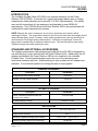
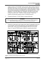
LPC 4300
Quick Reference Guide
Dranetz-BMI • 1000 New Durham Road • Edison, New Jersey 08818
Telephone 1-800-372-6832 or 732-287-3680
Fax 732-248-1834 • www.dranetz-bmi.com
\899036a.doc 4-1-98
Dranetz-BMI • 1000 New Durham Road • Edison, New Jersey 08818
Telephone 1-800-372-6832 or 732-287-3680
Fax 732-248-1834 • www.dranetz-bmi.com
\899036a.doc 4-1-98
QUICK REFERENCE GUIDE
LPC4300
WARNING
Death, serious injury, or fire hazard could result from improper connection of this
Instrument. Read and understand this manual before connecting this instrument.
Follow all installation and operating instructions while using this instrument.
Connection of this instrument must be performed in compliance with the
National Electrical Code (ANSI/NFPA 70-1996) and any additional safety
requirements applicable to your installation.
Installation, operation, and maintenance of this instrument must be performed
by qualified personnel only. The National Electrical Code defines a qualified
person as “one familiar with the construction and operation of the equipment
and the hazards involved.”
DEFINITIONS
WARNING statements inform the user that certain conditions or practices could result
in loss of life or physical harm.
CAUTION statements identify conditions or practices that could harm the Power
Platform, its data, other equipment, or property.
NOTE statements call attention to specific information.
SYMBOLS
The following International Electrotechnical Commission (IEC) symbols are on the top
and rear panel in the immediate vicinity of the referenced terminal or device:
CAUTION. Refer to accompanying documents (this manual).
ALTERNATING CURRENT. (AC) operation of the terminal or device.
Page 3
\899036a 4-1-98
QUICK REFERENCE GUIDE
LPC4300
SAFETY PRECAUTIONS
The following safety precautions must be followed whenever any type of connection is
being made to the instrument.
•
Connect the green safety (earth) ground first, before making any other
connections.
•
Connections must be made to the instrument first, then connect to the circuit to
be monitored.
•
When connecting to electric circuits or pulse initiating equipment, open their
related breakers. DO NOT install any connection of the instrument on live power
lines.
•
Wear safety glasses and insulated gloves when making connections to power
circuits.
•
Hands, shoes and floor must be dry when making any connection to a power
line.
•
Make sure the unit is turned OFF before connecting probes to the rear panel.
•
Before each use, inspect all cables for breaks or cracks in the insulation.
Replace immediately if defective.
Page 4
\899036a 4-1-98
QUICK REFERENCE GUIDE
LPC4300
STATEMENT OF WARRANTY
All products of Dranetz-BMI are warranted to the original purchaser against defective
material and workmanship for a period of one year from the date of delivery. DranetzBMI will repair or replace, at its option, all defective equipment that is returned, freight
prepaid, during the warranty period. There will be no charge for repair provided there
is no evidence that the equipment has been mishandled or abused. This warranty shall
not apply to any defects resulting from improper or inadequate maintenance, buyersupplied hardware/software interfacing, unauthorized modification or misuse of the
equipment, operation outside of environmental specifications, or improper site
preparation or maintenance.
STATEMENT OF RELIABILITY
The information in this manual has been reviewed and is believed to be entirely
reliable, however, no responsibility is assumed for any inaccuracies. All material is for
informational purposes only and is subject to change without prior notice.
NOTICE REGARDING PROPRIETARY RIGHTS
This publication contains information proprietary to Dranetz-BMI. By accepting and
using this manual, you agree that the information contained herein will be used solely
for the purpose of operating equipment of Dranetz-BMI.
COPYRIGHT
This publication is protected under the copyright laws of the United States, Title 17 et
seq. No part of this publication may be reproduced, transmitted, transcribed, stored in
a retrieval system, or translated into any language or computer language, in any form,
by any means, electronic, mechanical, magnetic, optical, chemical, manual, or
otherwise, without prior written consent of Dranetz-BMI, 1000 New Durham Road,
Edison, NJ 08818-4019.
Copyright © 1996, Dranetz-BMI
All rights reserved. Printed in the United States of America.
TRADEMARKS
Power Platform is a registered trademark of Dranetz-BMI.
Page 5
\899036a 4-1-98
QUICK REFERENCE GUIDE
LPC4300
INTRODUCTION
The Lockable Portable Case (LPC4300) is an optional accessory for the Power
Platform 4300 (PP4300). It consists of a rugged, high impact plastic case, a voltage
measurement cable assembly and a domestic 115 VAC cable assembly. The cables,
case and all connections to it are waterproof and designed to meet NEMA 4X
requirements. The LPC4300 allows the Power Platform 4300 to be operated and left
unattended in harsh industrial environments.
NOTE: Although the case is waterproof, do not use or locate the case where it will be
submerged in water. The purge valve (located on the front of the case near the handle) should
always be kept tightly closed. However, under certain conditions the case may be difficult to
open because of its airtight sealing characteristics. If difficulty is experienced, loosen the
purge valve to equalize the air pressure inside the case. The case should then open easily.
Tighten the purge valve after opening the case.
STANDARD AND OPTIONAL ACCESSORIES
The voltage measurement cable assembly provided with the LPC4300 is designed for
use with the plug-on clips included with the Power Platform 4300. Additionally, the AC
adapter included with the Power Platform 4300 is to be installed in the Lockable
Portable Case. Current measurements require the use of the optional current
transformer interface cable set. Additional plug-on clips, probes and AC adapters are
available. A conventional padlock for locking the case is user-supplied.
STANDARD ACCESSORIES
Description
Part Number
Voltage Measurement Cable Assembly
116183-G1
Domestic 115 VAC Cable Assembly
116187-G1
Quick Reference Guide, LPC4300
899036
OPTIONAL ACCESSORIES
Description
Part Number
Current Transformer Interface Cable Set
(consists of two cables)
CTIC-LPC4300
AC Adapter/Battery Charger
ACADP-LPC4300
SPECIFICATIONS
Size
Weight (without PP4300)
16" L x 13" W x 7" D
9 lbs.
Operating Temperature Range (with PP4300)
+41 to +113 °F (+5 to +45 °C)
Operating Humidity Range (non-condensing)
10-90% RH
Page 6
\899036a 4-1-98
QUICK REFERENCE GUIDE
LPC4300
Figure 1. Lockable Portable Case with PP4300 installed (shown without lid).
Figure 2. Standard cables provided with the LPC4300.
Set.
4300-111
Figure 3. Optional Current Transformer Interface Cable
4300-112
4300-113
Page 7
\899036a 4-1-98
QUICK REFERENCE GUIDE
LPC4300
SETTING UP THE LOCKABLE PORTABLE CASE
The AC adapter must be installed inside the case prior to mounting the PP4300.
Prepare the case for use as follows. Refer to Figures 1 and 4.
1.
Release both latches and open the case. (See note on page 5).
WARNING
Do not remove mounting plate until all power is de-energized to all circuits.
2.
Remove the four screws that retain the mounting plate.
Remove the mounting plate.
3.
Remove the upper piece of VelcroTM from inside the case. Expose the adhesive
backing and attach it to the bottom of the AC adapter. Surface must be clean.
4.
Mount the AC adapter inside the bottom of the case as shown in Figure 4.
5.
Connect the internal power cable to the AC adapter.
6.
Pass the AC adapter output cable through the hole in the mounting plate.
If necessary, remove the grommet and install it after the cable has been
positioned.
7.
Install the mounting plate in the case. Be sure the internal cables are not on
top of the mounting brackets. Install and tighten the four screws.
8.
Position the PP4300 on the mounting plate as shown. NOTE: Remove the
carrying strap from the PP4300 if installed.
9.
Engage the two studs on the back of the PP4300 in the mounting slots in the
mounting plate. Slide the PP4300 forward (toward the case handle) to secure
it to the
mounting
plate.
Figure 4.
Mounting AC
adapter inside case.
4300-114
Page 8
\899036a 4-1-98
QUICK REFERENCE GUIDE
LPC4300
CABLE CONNECTIONS
CAUTION
Do not connect or disconnect input cables until all power is de-energized to all
circuits. Make all connections to the rear panel of the PP4300 and the LPC4300
before making any connections to the circuit to be monitored.
1.
Connect the color coded and marked input cables inside the case to the rear
panel of the PP4300. The cable connector sequence and color scheme on the
PP4300 is identical to that of the LPC4300.
2.
Connect the AC adapter output cable to the DC INPUT connector on the right
side of the PP4300. See Figure 1.
3.
Connect the Domestic 115 VAC Cable (P/N 116187-G1) to the rear panel of the
LPC4300. The connector is marked “POWER INPUT 100-130 V~ 50-60 Hz”.
4.
If applicable, connect the optional Current Transformer Interface Cable Set (P/N
CTIC-LPC4300) to the rear panel of the LPC4300. The set consists of two
cables, P/N 116185-G1 (CH A,B) and P/N 116185-G2 (CH C,D). Connect the
cable labeled (A,B) to the connector marked “CURRENT INPUTS CHANNELS
A-B). Connect the cable labeled (C,D) to the connector marked “CURRENT
INPUTS CHANNELS C-D”.
5.
Connect the Voltage Measurement Cable (P/N 116183-G1) to the rear panel of
the LPC4300. The connector is marked “VOLTAGE INPUTS 600 VRMS MAX.
CHANNELS A-B-C-D”. NOTE: This cable must be installed and removed as
follows to assure proper sealing and prevent damage to the connector.
To install the cable, align the keyway in the cable connector with the tab in the
Page 9
\899036a 4-1-98
Figure 5. Rear panel connections, LPC4300.
QUICK REFERENCE GUIDE
LPC4300
mating connector on the LPC4300. Firmly push the cable connector inward and
tighten the locking ring. Push the cable connector inward again while rocking it
from side to side. Tighten the locking ring again. Repeat this operation several
times until the locking ring is hand tight and cannot be tightened further. A slight
gap will exist at the back edge of the locking ring. Removal is the reverse of
installation. Loosen the locking ring. Pull back on the cable connector while
rocking it from side to side. Loosen the locking ring again. Repeat this
operation until the cable connector is free of its mating connector.
6.
Connect the Domestic 115 VAC Cable to an appropriate outlet.
WARNING
Follow all safety precautions shown in this manual and the PP4300 Operator’s
Manual when making connections to the circuit to be monitored.
7.
Connect the voltage and current measurement cables (if applicable) to the circuit
to be monitored. Use the probes and plug-on clips provided with the Power
Platform 4300. Refer to the connection diagrams inside the lid of the case
(Figure 6). See the PP4300 Operator’s Manual for operating instructions.
Figure 6. LPC4300 Connection Diagram (inside lid of case).
4300-
116
Page 10
\899036a 4-1-98
Dranetz-BMI • 1000 New Durham Road • Edison, New Jersey 08818-4019
Telephone 1-800-372-6832 or 732-287-3680
Fax 732-248-1834 • www.dranetz-bmi.com