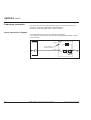
1
Comet ™
5 - 30 kVA
installation and user manual
!
!
fault
GERIN
MERtLIN
come
S
SYSTEM
E UPS
BY MG
E-6761200XT/FC
MERLIN GERIN
BY
MGE
UPS
SYSTEMS
Dear User,
This manual has been designed to provide you with all the information you need
to install and use your Comet uninterruptible power supply.
Feel free to contact us for any further information you may require concerning
special applications beyond the scope of this manual.
MGE UPS SYSTEMS
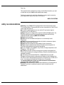
safety recommendations
■ warning: every Comet UPS is equipped with its own internal power source,
i.e. the backup battery. Consequently the load may energised even if the AC input
power supply has been cut;
■ the load is supplied with power as soon as the AC input power supply is
connected, even if no LEDs are on;
■ danger: dangerous voltage levels are present inside the Comet system. Any
servicing requiring removal of the protection panels must be carried out by
qualified personnel certified by MGE UPS SYSTEMS;
■ Comet must be earthed;
■ Comet must not be installed near liquids or in an excessively humid
environment;
■ Comet must be protected from penetration by liquids or extraneous objects;
■ ventilation grates must remain free;
■ Comet must not be placed in direct sunlight or near a heat source;
■ Comet contains sealed lead-acid battery cells that must be disposed of in
accordance with applicable environmental regulations;
■ prior to installation, store Comet in a dry location. Storage temperatures must
be between: –20°C and +45°C ;
■ if Comet must remain unused for a long period, monthly re-energising for a
24-hour period is advised to recharge the battery. Otherwise, the battery may be
damaged irreversibly;
■ in accordance with standard EN 50091-1, Comet UPS users must affix
warnings on all primary power isolating devices installed a certain distance from
the UPS in order to alert maintenance personnel of the presence of a UPS on the
circuit; the warning must display the following text or its equivalent:
"an uninterruptible power supply is present and must be isolated before
carrying out any work on this circuit";
■ warning: this is a product for restricted sales distribution to informed partners.
Installation restrictions or additional measures may be needed to prevent
disturbances.
0
Comet installation and user manual: E-6761200XT/FC
Merlin Gerin by MGE UPS SYSTEMS
DANSK
sikkerhedsforskrifter
NORSK
c advarsel: Comet er forsynet med indbyggede eller eksternt tilsluttede
batterier. Udstyret kan derfor være strømførende, selv om det ikke er tilsluttet den
almindelige elforsyning;
c udstyret er strømførende så snart det er tilsluttet den almindelige elforsyning,
selv om frontpanelets lamper er slukkede;
c fare: der er højspænding i en Comet. Indgreb indenfor beskyttelsespladerne
må derfor kun foretages af specielt uddannet personale eller teknikere godkendt
af MGE UPS SYSTEMS;
c Comet må aldrig benyttes uden jordforbindelse;
c Comet må ikke benyttes i nærheden af væsker, eller i omgivelser med høj
luftfugtighed;
c det skal sikres, at fremmedlegemer og væsker ikke kan trænge ind i udstyret;
c det skal sikres, at ventilationsgitrene aldrig er tilstoppede;
c Comet må ikke opstilles i stærkt sollys eller i varme omgivelser;
c Comet er udstyret med lukkede blybatterier. Ved destruktion eller bortskaffelse
skal der tages hensyn til den til enhver tid gældende lovgivning for batteriaffald;
c oplagring af Comet inden igangsættelsen må kun finde sted i et rent, tørt
lokale, hvor temperaturen holdes indenfor -20°C til +45°C;
c hvis Comet ikke benyttes gennem en længere periode, skal batterierne
vedligeholdslades ca 24timer en gang om måneden, for at sikre at de ikke bliver
ødelagt;
c advarsel: det drejer sig om et produkt, der kun sælges til erfarne installatører
eller brugere. For at undgå forstyrrelser kan det være nødvendigt at foretage
begrænsninger i forbindelse med installationen eller at gennemføre yderligere
forholdsregler.
sikkerhedsforskrifter
■ obs: Comet er utstyrt med en uavhengig energikilde (batteri). Apparatet kan
derfor være strømførende selv om det ikke er koplet til strømnettet;
■ apparatet er strømførende fra det øyeblikk det koples til strømnettet, selv om
signallampen ikke lyser;
■ advarsel: de interne spenningene i apparatet kan være farlige! Ethvert inngrep
som medfører åpning av beskyttelsesdekslene, må derfor utelukkende overlates
til spesielt utdannede teknikere som er godkjent av MGE UPS SYSTEMS;
■ det er absolutt påkrevet at apparatet koples til en jordet stikkontakt;
■ unngå å plassere apparatet i nærheten av væsker eller i et sterkt fuktig miljø;
■ pass på at væsker eller fremmede gjenstander ikke trenger inn i apparatet;
■ unngå å tette til lufteventilene;
■ Ikke plassér apparatet i sterkt sollys eller i nærheten av en varmekilde;
■ Comet er utstyrt med batterier som inneholder vanntett bly. Kastes batteriene
eller annet batteriavfall, må det skje i overensstemmelse med gjeldende lov;
■ lagres apparatet før bruk, må det plasseres på et tørt sted hvor temperaturen
ligger mellom –20°C og +45°C;
■ dersom apparatet ikke brukes i lengre perioder, tilrådes det å kople det til
strømnettet ca. én gang i måneden i 24 timer. Dermed opplades batteriet.
Unnlater man å gjøre dette, kan batteriet ødelegges definitivt;
c advarsel: dette produktet skal kun selges til erfarne installatører eller brukere.
For å unngå forstyrrelser kan begrensninger i.f.m. installasjon eller ytterligere
sikkerhetstiltak være nødvendig.
Merlin Gerin by MGE UPS SYSTEMS
Comet : 6761200XT/FB
i
PORTUGUÊS
recomendações de segurança
■ Atenção: o Comet possui a sua própria fonte de energia interna (bateria).
Deste modo, a utilização pode ficar sob tensão, caso a rede eléctrica de
alimentação seja cortada;
■ a utilização fica sob tensão, a partir do momento em que a rede eléctrica de
alimentação esteja presente, mesmo se não houver sinalização luminosa activa;
■ perigo: existem tensões perigosas no interior do Comet. Qualquer
intervenção que que exija a abertura dos paineis de protecção, só pode ser feita
por pessoal qualificado pela MGE UPS SYSTEMS;
■ o Comet deve ser, imperativamente, ligado à terra;
■ não colocar o Comet próximo de líquidos ou num ambiente demasiado
húmido;
■ evitar a penetração de qualquer líquido ou objectos estranhos para o interior
do Comet;
■ não obstruir as grelhas de ventilação do Comet;
■ não colocar o Comet à exposição do sol ou junto de uma fonte de calor;
■ o Comet contém na bateria, elementos em chumbo estanque, cujos detritos
deverão ser entregues a entidades competentes para a devida reciclagem;
■ em caso de armazenamento antes da colocação em serviço, colocar o Comet
num local seco. Limites de tempertura de armazenamento: –20°C a +45°C;
■ caso o Comet tenha de ficar desligado durante um período de tempo longo, é
aconselhável, cerca de uma vez por mês, colocá-lo sob tensão cerca de 24h, de
forma a recarregar a bateria e evitar a sua degradação irreversível;
c advertência: trata-se de um produto para distribuição restrita aos instaladores
ou utilizadores experientes. Certas restrições na instalação ou certas medidas
adicionais podem vir a ser necessárias para evitar as perturbações.
ii
Comet : 6761200XT/FB
Merlin Gerin by MGE UPS SYSTEMS
SUOMALAINEN
turvallisuusohjeet
■ huomio: Comet omistaa oman sisäisen energialähteensä (patteristo).
Virta voi siis laitteessa olla päällä, vaikka sähköverkko onkin katkaistu;
■ virta on päällä heti, kun sähköverkosto on kytketty, vaikkei merkkivaloa olekaan
syttynyt;
■ varoitus: Cometin sisällä on vaarallisia jännitteitä. Ainoastaan
MGE UPS SYSTEMS’n valtuuttama pätevä henkilökunta voi suorittaa
suojakilpien avaamista vaativia toimia;
■ Comet on välttämättä liitettävä maavirtaan;
■ älkää koskaan asettako Cometia ympäristöön, jossa se voisi joutua
kosketuksiin nesteiden tai liiallisen kosteuden kanssa;
■ älkää koskaan antako nesteiden tai vieraiden esineiden päästä Cometin
sisälle;
■ älkää koskaan peittäkö Cometin ilmanvaihtoristikkoa;
■ älkää asettako laitetta suoraan auringonvaloon tai lämmölähteen lähelle;
■ Comet sisältää patterielementtejä vedenpitävästä lyijystä. Niiden
hävittämisessä on noudatettava voimassa olevaa lakia;
■ mikäli ette ota laitetta heti käyttöön, on se varastoitava kosteudelta suojattuun
paikkaan; ei alle –20°C tai yli +45°C lämpötilaan;
■ jos Comet joutuu pitkään olemaan kytkemättömänä, suosittelemme sen
kytkemistä noin kerran kuukaudessa 24 tunnin ajaksi, patteriston uudelleen
lataamiseksi. Muutoin se voisi turmeltua peruuntumattomasti;
c varoitus: tämä tuote on tarkoitettu rajoitettuun myyntiin tuotteisiin perehtyneille
liikekumppaneille. Asennukseen liittyvät rajoitukset tai muut lisätoimenpiteet ovat
ehkä tarpeen häiriöiden estämiseksi.
Merlin Gerin by MGE UPS SYSTEMS
Comet : 6761200XT/FB
iii
SVENSK
säkerhetsföreskrifter
■ observera: Comet har en egen intern kraftkälla (batteri). Apparaten kan därför
vara strömsatt även om den inte är ansluten till elnätet;
■ apparaten är strömsatt så snart den är ansluten till elnätet, även om ingen
kontrollampa är tänd;
■ varning: det finns farliga spänningar i Comet. Ingrepp som kräver att
skyddshöljet avlägsnas får endast utföras av kvalificerad, och av MGE UPS
SYSTEMS godkänd, personal;
■ Comet måste ovillkorligen anslutas till ett jordat uttag;
■ placera aldrig Comet i en lokal med hög luftfuktighet eller där den kan komma i
kontakt med vätska;
■ låt aldrig vätska eller främmande föremål komma in i Comet;
■ täck aldrig för Comets ventilationsgaller;
■ placera aldrig Comet i direkt solljus eller i närheten av en värmekälla;
■ Comet har ett kapslat batteri med blyelement. Dessa får endast slängas i
enlighet med gällande lag;
■ skall apparaten lagras före användning måste den förvaras i ett torrt utrymme.
Apparaten får ej utsättas för temperaturer under –20°C eller över +45°C;
■ Om Comet inte skall användas under en längre tid rekommenderar vi att
apparaten strömsätts ca 1 gång i månaden under minst ett dygn för uppladdning
av batteriet. Om detta inte sker kan batteriet skadas definitivt;
c varning: beträffande en produkt avsedd för begränsad distribution till på
förhand underrättade installatörer eller konsumenter. Restriktioner vid
installationen eller extra tillkommande åtgärder kan vara nödvändiga för att
undvika störningar.
iv
Comet : 6761200XT/FB
Merlin Gerin by MGE UPS SYSTEMS
contents
introduction to Comet
safety information .............................................................................................
identification to Comet .....................................................................................
configuration ....................................................................................................
functional diagram ............................................................................................
1.1
1.1
1.1
1.2
general .............................................................................................................
final positioning ................................................................................................
special precautions ..........................................................................................
connections ......................................................................................................
2.1
2.1
2.2
2.2
installation
controls and indications
basic controls and indications .......................................................................... 3.1
controls and diagnostics display ...................................................................... 3.4
start-up
preliminary checks ........................................................................................... 4.1
powering up ..................................................................................................... 4.1
inverter start-up ................................................................................................ 4.2
shutdown
inverter shutdown ............................................................................................. 5.1
powering down ................................................................................................. 5.1
operation
normal operation .............................................................................................. 6.1
operation on battery power .............................................................................. 6.1
overload ........................................................................................................... 6.3
alarms
alarm indications table ..................................................................................... 7.1
manual bypass ................................................................................................. 7.3
communication
standard functions ............................................................................................ 8.1
options .............................................................................................................. 8.2
Merlin Gerin by MGE UPS SYSTEMS
Comet installation and user manual: E-6761200XT/FA
1
contents (cont')
maintenance and servicing
safety reminder ..............................................................................................
preventive maintenance by user ....................................................................
maintenance by the local representative certified by MGE UPS SYSTEMS .
customer training ...........................................................................................
maintenance contracts ...................................................................................
9.1
9.1
9.1
9.1
9.2
extended battery cabinet .................................................................................
emergency off .................................................................................................
full galvanic isolation transformer ....................................................................
separate Mains 2 transformer (AC bypass input) ...........................................
frequency converter ........................................................................................
hot standby system .........................................................................................
harmonics filter ................................................................................................
combined options ............................................................................................
10.1
10.3
10.4
10.5
10.6
10.7
10.8
10.9
general characteristics ....................................................................................
range characteristics .......................................................................................
Comet series 11 general characteristics .......................................................
Comet series 31 general characteristics .......................................................
Comet series 33 general characteristics .......................................................
selection of cable cross-sections ....................................................................
selection of protection devices ........................................................................
connection of cable shielding ..........................................................................
11.1
11.1
11.2
11.3
11.4
11.5
11.6
11.8
options
appendices
glossary
........................................................................................................................ 12.1
Comet and the options presented in this manual must be installed only by qualified
personnel. Other operations may be carried out by any person having read this manual.
All Comet products are protected by patents. They implement original MGE UPS
SYSTEMS technology not available to other manufacturers.
Due to evolving standards and technology, products may be modified without notice.
Indications concerning technical characteristics and dimensions are not binding unless
confirmed by MGE UPS SYSTEMS.
This document may be copied only with the prior written consent of MGE UPS SYSTEMS.
Authorized copies must be marked "Comet MGE UPS SYSTEMS installation and user
manual nr. 6761200XT".
2
Comet installation and user manual: E-6761200XT/FA
Merlin Gerin by MGE UPS SYSTEMS
introduction to Comet
safety information
Danger: high voltages are present inside the Comet system. Any servicing
requiring removal of the protection covers may be undertaken only by qualified
personnel certified by MGE UPS SYSTEMS.
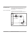
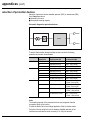
identification to Comet
Read the label (figure 1) on the back of Comet or inside the door to familiarise
yourself with the characteristics of your UPS.
Identification plate
MERLIN GERIN
comet S.(1)
RESEAU 1 - MAINS 1 - NETZ 1
1
Mains 1 characteristics
(AC input)
2
Mains 2 characteristics
(optional AC bypass
input)
3
load characteristics
4
serial number
RESEAU 2 - MAINS 2 - NETZ 2
UTILISATION - LOAD - AUSG
Fig. 1
(1): Comet model number:
■ S11 (series 11): single-phase input power and single-phase load;
■ S31 (series 31): three-phase input power and single-phase load;
■ S33 (series 33): three-phase input power and three-phase load.
configuration
A configuration sheet, included with the UPS, indicates all the factory settings.
Keep the sheet in a safe place as it may be required by the after-sales support
technicians if you wish to modify parameters.
Merlin Gerin by MGE UPS SYSTEMS
Comet installation and user manual: E-6761200XT/FA
1.1
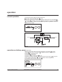
introduction to Comet (cont')
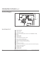
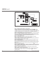
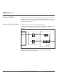
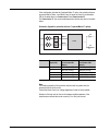
functional diagram
3
load
AC input
1
2
6
5
4
7
8
Fig. 7
key for figures 2 to 7
1.2
1
input power switch,
2
rectifier module,
3
"static bypass" module,
4
battery circuit breaker (switch and fuse for 5 kVA Comet S11 or S31),
5
battery,
6
charger module,
7
inverter module,
8
"manual maintenance bypass" switch,
9
basic control and indication panel,
10
special command and diagnostic display,
11
location of the optional communication ports,
12
fans,
13
connection cover panel,
14
diagnostics and configuration connector (reserved for after-sales support),
15
standard communication port,
16
switchgear cover panel,
43
protection panel,
44
protective cover.
Comet installation and user manual: E-6761200XT/FA
Merlin Gerin by MGE UPS SYSTEMS
installation (for qualified personnel only)
general
■ "Comet" cubicles are equipped with 4 wheels for moving over short distances
and with jacks to immobilize the unit. The jacks must be raised prior to
repositioning a cubicle;
■ operating temperature range: 0° to 30°C at rated output.
Important:
■ the battery is of the sealed type. Battery storage or prolonged shutdown
of Comet should never exceed 3 months at 20°C without recharging, for a
battery initially at 100% charge. Battery recharge requires system start-up.
The battery warranty is void if the 6 month recharge interval is not
respected;
■ battery life is extended when it is installed in a room with an ambient
temperature of 15 to 25°C. Above 25°C, battery life reduced by 50% for
every additional 10°C;
■ heat loss resulting from Comet operation must be taken into account when
sizing the ventilation system. See the Appendices;
■ connections are made through the bottom section in the back or the front,
depending on the type of Comet;
■ warning in compliance with EN 50091-2: this product is sold through limited
sales channels to installers or well-informed users. Installation restrictions or
additional measures may be necessary to prevent electromagnetic disturbances.
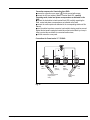
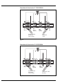
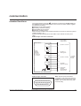
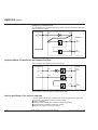
final positioning (figure 8)
"Comet" layout seen from above
100 mm minimum
(for ventilation)
L1
L
"e" see note
L2
L2
P
air extraction
Comet
extended battery
option
other option
P1
Fig. 8
Merlin Gerin by MGE UPS SYSTEMS
Comet installation and user manual: E-6761200XT/FC
2.1
installation (cont')
Note:
For Comet series 31 15/20kVA and Comet series 33 units, a clearance "e" of
5mm is required to the left of the optional cubicles for door opening.
■ ensure that clearance L1 to the left of Comet is greater than L for access to the
battery cells and L2 greater than 100mm (for ventilation);
■ ensure that clearance P1 in front of Comet is greater than P for servicing via
the front;
■ connection cables must be of th flexible type and sufficiently long to enable
forward movement of Comet without disconnection (allow an extra 1.5 meters);
■ additional cubicles (extended battery, auxiliaries, etc.) must be placed to the
right of Comet. If the above installation conditions are not respected,
maintenance and servicing of the unit may require system shutdown.
special precautions
■ load cables must be run separately from all other cables (power supply or
computer system interconnection cables). They should not pass near
interference-emitting equipment or sensitive loads;
■ if Comet is installed with the "Teleservice" option, a telephone connector and
power supply must be provided for the modem used with it.
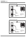
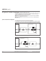
connections
Connection cables should enter at the bottom:
■ in the back for Comet series 11 and series 31 5/7.5/10kVA;
■ in front for Comet series 31 15/20 kVA and series 33 10/15/20/30kVA.
electrical diagram for power connections
Figure 9 presents a single-line electrical diagram for a typical installation.
The power cables requiring connection are shown as bold lines (see the
"appendices" for information on selecting cable cross-sections).
Connection diagram for a single AC input
Comet
AC input
XR1
XR2
load
XR3
XR3
extended battery
cubicles (optional)
Fig. 9
2.2
Comet installation and user manual: E-6761200XT/FC
Merlin Gerin by MGE UPS SYSTEMS
connection of power cables (figures 10 to 14)
Make sure the unit is powered down and disconnected from all input power
before making connections to the terminal blocks at the front or back of the
cubicle (depending on the type of Comet).
For protection of life and property, earth wires should always be connected
first.
For Comet 31 series or Comet 33 series devices, the Mains power supply
must be with a neutral cable.
For Comet 33 series, the neutral may be reconstituted by a complete insulation
transformer option (a transformer with a triple-point structure).
Neutral system: identical upstream and downstream neutral systems (no
galvanic isolation). Comet can be used with all types of neutral systems, on the
condition that standard practices be respected.
■ check that AC input power circuit breaker, installed upstream on the low voltage
switchboard, is in off (O) position;
■ check that the input power switch 1 and the battery circuit breaker 4 are in
off (O) position.
Connection sequence for 5 kVA Comet:
■ open the protective cover 44 (secured by 2 screws) and the connection cover
panel 13 (secured by 6 screws);
■ strip the duct of the AC input power and load cables over a length of 7 cm;
■ strip each wire over a length of 1 cm;
■ insert the cables of the AC input power and load through the bushings of the
connection cover panel;
■ connect the cables of the AC input power to "Mains 1" XR1 terminal block in
the order shown on the label;
■ connect the load cables to the "load" XR2 terminal block in the order shown on
the label;
■ connect the various options as shown in the relevant section for each one in
this manual;
■ when the cables have been connected, the duct of each cable must be
tightened by a binding band against the horizontal binding bar placed beneath the
terminal block in order to protect the conductors from tensile loads;
■ put back the connection cover panel 13 and the protective cover 44 .
Merlin Gerin by MGE UPS SYSTEMS
Comet installation and user manual: E-6761200XT/FC
2.3
installation (cont')
Connections for Comet series 11 5kVA
L L+
N L1
XR2
load
L1
N
XR3
battery
(optional)
XR1
Mains 1
to load
(single-phase
+ earth)
L1
N
from LV switchboard
(single-phase +
earth)
XR1
Mains 2
(optional)
see the paragraph on
"connection of the cable
shielding" in the section
"appendices"
Fig. 10
Connections for Comet series 31 5kVA
L L+
N L1
XR2
load
L1
N
XR3
battery
(optional)
XR1
Mains 1
L3
L2
L1
N
XR1
Mains 2
(optional)
to load
(single-phase + earth)
from LV switchboard
(three phases,
neutral and earth)
see the paragraph on
"connection of the cable
shielding" in the section
"appendices"
Fig. 11
2.4
Comet installation and user manual: E-6761200XT/FC
Merlin Gerin by MGE UPS SYSTEMS
Connection sequence for Comet other than 5kVA:
■ remove the connection cover panel 13 that is secured with screws;
■ connect the AC input cables to Mains 1 terminal block XR1, carefully
respecting earth, neutral and phase correspondence as indicated on the
label;
■ connect the load cables to load terminal block XR2 carefully respecting the
earth, neutral and phase correspondence as indicated on the label;
■ connect the various options as indicated in the corresponding sections of this
manual;
■ once the cables have been connected, each cable’s sleeving must be secured
against the horizontal hooping bar located above the terminal block by a hoop in
order to protect the conductors from eventual tensile stress;
■ refit the connection cover panel.
Connections for Comet series 11 7.5/10kVA
N L1
XR1
Mains 1
N L1
XR1
Mains 2
(optional)
from LV switchboard
(single-phase +
earth)
L L+
N L1
XR2
load
XR3
battery
(optional)
to load
(single-phase
+ earth)
Fig. 12
Merlin Gerin by MGE UPS SYSTEMS
Comet installation and user manual: E-6761200XT/FC
2.5
Connections for Comet series 31 7.5/10/15/20kVA
N L1 L2 L3
XR1
Mains 1
N L1
XR1
Mains 2
(optional)
from LV switchboard
(three phases,
neutral and earth)
L L+
N L1
XR2
load
XR3
battery
(optional)
to load
(single-phase
+ earth)
Fig. 13
Connections for Comet series 33 10/15/20/30kVA
N L1 L2 L3
XR1
Mains 1
N L1 L2 L3
XR1
Mains 2
(optional)
from LV switchboard
(three phases
neutral and earth)
L L+
N L1 L2 L3
XR2
load
XR3
battery
(optional)
to load
(three-phases, neutral
and earth)
Fig. 14
2.6
Comet installation and user manual: E-6761200XT/FC
Merlin Gerin by MGE UPS SYSTEMS
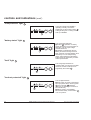
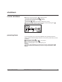
controls and indications
Comet operating controls are made up of (see figure 15):
■ basic controls and indications 9 concerning the overall operating status of the
UPS;
■ the special command and diagnostic display panel 10 include specific controls
and a 2-digit display for the UPS fault numbers. These numbers provide UPS
diagnostics.
Controls and indications
basic controls
and indications
panel 9
!
!
!
!
fault
fault
special
command and
diagnostic
display 10
Fig. 15
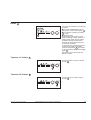
basic controls and indications
Positioned in the upper left-hand corner of the front panel, this panel provides
information on the operating status of the system (see figure 16).
Interpretation of signals is very easy and requires no special training.
They indicate:
■ normal operation (load protected);
■ downgraded operation (fault);
■ danger of a break in the supply of power to the load (load not protected);
■ operation on battery power.
!
17
!
18 19
I
+–
20 21
22
O
23
Fig. 16
Merlin Gerin by MGE UPS SYSTEMS
Comet installation and user manual: E-6761200XT/FA
Key to figure 16 :
17 buzzer,
18 "load not protected" light,
19 "fault" light,
20 "battery status or operation on
battery power" light,
21 "load protected" light,
22 "inverter on" button,
23 "inverter off" button.
3.1
controls and indications (cont')
"load protected" light
21
!
!
I
+–
O
This light indicates that Comet is
operating normally. The load is
supplied by via the inverter output 7 .
This light also goes on during normal
start-up of Comet.
21
"battery status" light
20
!
!
+–
I
O
20
"fault" light
This orange light indicates:
■ inverter 7 operation on battery
power following an AC input failure or
detection of an AC input voltage
outside tolerances;
■ it flashes to indicate that the low
battery shutdown warning level has
been reached. If the light flashes when
the battery is not in self-operating
phase, this indicates that the battery
status should be checked by an AfterSales representative.
19
!
!
+–
I
O
This orange light indicates an
operating fault or an environment fault.
However, the load continues to be
supplied by the inverter 7 .
19
"load not protected" light
18
!
!
+–
I
O
18
3.2
Comet installation and user manual: E-6761200XT/FA
This red light indicates:
■ direct supply of power to the load by
AC input power via the "static bypass"
3 due to inverter 7 shutdown
(voluntary or following an overload or
an internal fault);
■ battery power is not available
because the battery circuit breaker 4
is in "off" position.
Merlin Gerin by MGE UPS SYSTEMS
buzzer
17
bip...bip...
!
!
O
I
+–
17
"inverter on" button
The buzzer is activated in the following
situations:
■ the load is supplied directly by AC
input power via the "static bypass" 3 ;
■ the inverter is operating on battery
5 power;
■ operating faults.
It beeps softly and slowly for minor
faults and during inverter operation on
battery power. When the low battery
shutdown warning level has been
reached, the level and the frequency
of the beeps increases.
In the event of an inverter shutdown, a
continuous load alarm is emitted.
A buzzer reset button 24 is provided
on the controls and diagnostics display
panel 10.
Detection of a new fault will set the
buzzer off again.
22
This green button is used to start the
inverter 7 .
!
!
I
+–
O
22
"inverter off" button
23
This grey button is used to stop the
inverter 7 .
!
!
+–
I
O
23
Merlin Gerin by MGE UPS SYSTEMS
Comet installation and user manual: E-6761200XT/FA
3.3
controls and indications (cont')
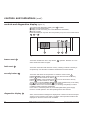
controls and diagnostics display (figure 17)
The controls and diagnostics display panel 10 includes:
■ display of environment faults;
■ display of faults concerning one of the Comet sub-assemblies;
■ specific controls.
Faults are displayed only when the user presses (once) one of the control buttons
24 , 25 or 26 .
fault
27
25
26
24
Fig. 17
buzzer reset
24
This button enables the user to stop buzzer 17 operation. Detection of a new
alarm will set the buzzer off again.
fault reset
25
This button clears the faults stored in memory. Clearing of alarms in memory is
accepted only once the alarm conditions themselves have been cleared.
security button
26
This button authorises forced operation or shutdown of the inverter 7 .
Forced shutdown: press simultaneously and for three seconds the security
button 26 and the "inverter off" button 23 .
Forced operation: press simultaneously and for three seconds the security
button 26 and the "inverter on" button 22 .
This key also controls a battery manual test: press simultaneously on the safety
key 26 and on the buzzer stop key 24 for 3 seconds.
Important: this function causes the battery to discharge completely in order to
update the battery monitoring parameters.
In the event of a network power cut, the uninterrupted battery power supply
returns to normal operation. The self-operating time is thus reduced.
diagnostics display
27
Alarm, fault and status messages are displayed as numerical codes. See chapter
"alarms" for the meaning of the codes. The alarm-code equivalence table is also
displayed on the door or at the back of Comet.
3.4
Comet installation and user manual: E-6761200XT/FA
Merlin Gerin by MGE UPS SYSTEMS
start-up
preliminary checks
■ check the settings of the protection devices:
■ input power switch 1 in off (O) position,
■ battery circuit breaker 4 in off (O) position,
■ "manual bypass" 8 switch set to "NORMAL" position (see figure 18);
■ check that nothing can block the ventilation system (air entry through the
bottom and, where applicable, through the side vents);
■ check that there is a minimum 100mm clearance at the back for ventilation;
■ check that Comet no longer rests on its 4 wheels (lifting jacks in place);
■ check that the load-circuit circuit breakers (where applicable) are in off (O)
position.
"manual maintenance bypass"
switch
TEST 1
NORMAL
BY-PASS
TEST 2
Fig. 18
powering up to Comet
Caution:
As soon as AC input power is supplied to Comet (upstream circuit breaker
on the low voltage switchboard in "on" position), the load is supplied via
the "static bypass" 3 . No indications are given on the control panel.
bip...bip...
!
17
!
I
+–
21
O
22
■ put first the input power switch 1 and then the battery circuit breaker 4 in
"on" position:
■ the buzzer 17 sounds,
■ the green "load protected" light 21 goes on,
■ the rectifier 2 and the charger 6 start up,
■ the inverter
7 automatically starts up, except if the system is in "manual
start-up" mode (optional). In this case, press the green "inverter on" button 22 .
Merlin Gerin by MGE UPS SYSTEMS
Comet installation and user manual: E-6761200XT/FA
4.1
start-up (cont')
If the transfer conditions (AC input power within tolerances) are correct, the
inverter comes on line and supplies the load,
■ the green "load protected" light 21 remains on,
In the event of a fault, the red "load not protected" light goes on. See the "alarms
section".
!
!
I
+–
18
21
O
22
inverter start-up (system in manual start-up mode)
■ press the green "inverter on" button 22 :
■ the green "load protected" light 21 flashes,
■ the inverter 7 starts and if the transfer conditions are correct, the load is
transferred to the inverter,
■ the red "load not protected" light 18 goes off,
■ the green "load protected" light 21 goes on.
!
18
4.2
!
I
+–
O
21 22
Comet installation and user manual: E-6761200XT/FA
Merlin Gerin by MGE UPS SYSTEMS
shutdown
inverter shutdown
■
■
■
■
■
■
■
press the "inverter off" button 23 for three seconds:
the green "load protected" light 21 goes off,
the red "load not protected" light 18 goes on,
the buzzer 17 sounds,
the inverter 7 stops if the transfer conditions are correct,
the load is supplied directly by AC input power via the "static bypass" 3 ;
in the event of fault, see the Alarms section.
bip...bip...
!
17
18
!
I
+–
21
O
23
powering down
It is recommended not to power down Comet for long periods because the
battery should remained charged. However, to carry out a power down, proceed
as follows:
■ shutdown the inverter 7 ;
■ put the battery circuit breaker 4 in "off" position;
■ turn off the input power switch
1 ;
■ all the indicating lights on the control panel go off.
Caution:
The load is still supplied by AC input power via the "static bypass" 3 ;
■ put the upstream circuit breaker(s) on the low voltage switchboard in "off"
position.
Merlin Gerin by MGE UPS SYSTEMS
Comet installation and user manual: E-6761200XT/FA
5.1
5.2
Comet installation and user manual: E-6761200XT/FA
Merlin Gerin by MGE UPS SYSTEMS
operation
normal operation
The AC input power supply is present (figure 19):
■ the green "load protected" light 21 is on;
■ the power drawn by the load is supplied by AC input power via the rectifier 2
and inverter 7 modules. The charger 6 float charges or recharges the battery
5 . The DC output voltage of the charger is temperature regulated to ensure an
optimal charge voltage.
!
!
I
+–
O
21
AC input
load
7
2
6
5
Fig. 19
operation on battery power (figure 20)
When AC input power fails or exceeds tolerances, the rectifier 2 and the
charger 6 shut down. The battery 5 supplies the power required by the
inverter 7 to supply the load.
The battery 5 discharges.
The green "load protected" light 21 is on.
The user is warned of operation on battery power by the buzzer 17 and by the
orange "battery status" light 20 . This information is also available via
the standard communication connector 15 .
bip...bip...
!
17
Merlin Gerin by MGE UPS SYSTEMS
!
+–
I
O
20 21
Comet installation and user manual: E-6761200XT/FA
6.1
operation (cont')
3
AC input
load
7
2
6
5
Fig. 20
battery duration
During an AC input power failure, the duration of inverter operation on battery
power depends on:
■ the rated capacity of the battery;
■ the power drawn by the load;
■ the battery temperature;
■ the age of the battery.
The rated backup time corresponds to a minimum for a new battery and with the
inverter operating at the rated load.
The real backup time, which depends on the power drawn, may be greater if the
inverter operates at less than full rated load. It is possible, during operation on
battery power, to increase the battery backup time by reducing the power drawn
by the load (shedding of non-priority circuits).
Comet has a battery monitoring function that calculates the remaining backup
time. This function may be implemented with a communications option.
A low battery shutdown warning signal is available via the standard
communication connector 15 for remote indications. It warns the user of
upcoming battery shutdown at a user-determined level of remaining power.
On the UPS itself, the buzzer 17 beeps louder and more rapidly, and the
orange "battery status" light 20 flashes.
The end of battery power occurs when the battery is fully discharged. At this
point, the inverter 7 shuts down.
The recharge time required to restore the battery to its rated backup power varies
between 4 and 16 hours depending on the Comet model.
return of AC input power
When the AC input power failure ends or power returns to within tolerances:
■ if the end of battery backup power was not reached, Comet returns to the
operating status described above (figure 19);
■ if the end of battery backup power was reached, the rectifier 2 , the
charger 6 and the inverter 7 automatically start up (the inverter must be
manually started if the system is in manual start mode).
6.2
Comet installation and user manual: E-6761200XT/FA
Merlin Gerin by MGE UPS SYSTEMS
battery monitoring tests
■ the battery is periodically checked every month. The message "17" on the
diagnostics display 27 tells the user that the battery is in this operating mode;
■ it is recommended to carry out a complete discharge test on the battery once a
year in order to update the battery monitoring parameters. This test is activated
by the "battery manual test" control. It calls for a minimum service charge. The
message "18" on the diagnostics display 27 tells the user that the battery is in
this operating mode.
In these operating modes, total battery failure is indicated by the alarm message
"15" on the diagnostics display 27 .
overload
(except for 5 kVA Comet S11 or S31)
■
■
■
■
during a major temporary overload (greater than 1.5In):
the load is supplied by AC input power via the "static bypass" 3 ,
return to the inverter 7 is automatic, following elimination of the overload;
the inverter can handle a minor overload for a given duration depending on the
size of the overload. See figure 21;
■ when an overload occurs:
■ the buzzer 17 sounds,
■ the orange "fault" light 19 goes on,
■ the inverter 7 shuts down at the end of its corresponding overload time,
■ the load is supplied by AC input power via the "static bypass" 3 ,
■ the green "load protected" light 21 goes off,
■ the red "load not protected" light 18 goes on.
If the overload continues during operation via the "static bypass" 3 , the supply
of power to the load is interrupted after a specified time. See figure 22.
When Comet has shutdown due to an overload, the fault reset button must be
pressed prior to return to normal operation.
Inverter 7 overload curve
time
10 mn
1 mn
10 s
1s
rated load
current In
0,15 s
1,05 1,1
1,3
1,5
1,7
1,9
2
Fig. 21
Merlin Gerin by MGE UPS SYSTEMS
Comet installation and user manual: E-6761200XT/FA
6.3
operation (cont')
"Static bypass" 3 overload curve
time
10 mn
1 mn
10 s
1s
rated load
current In
0,15 s
1,05 1,1
1,3
1,5
1,7
1,9
2
Fig. 22
overloads on 5 kVA Comet S11 or S31
For a major temporary overload (greater than 1.5In):
The load is transferred to AC input power via the "static bypass" 3 for 5 seconds.
After that time, it is transferred back to the inverter.
If the overload persists, this sequence will be repeated 3 times in all before the
inverter is shut down and the supply of power to the load interrupted.
For a minor overload:
Minor overloads can be supplied by the inverter for a duration defined in figure 21
for an ambient temperature of less than 30°C. Above this temperature, a derating
coefficient k must be applied to the rated current and therefore to the overload
curve in figure 21:
■ from 30°C to 35°C: k = 0.9,
■ from 35°C to 40°C: k = 0.85,
■ above 40°C: k = 0.8.
Example: an overload current I can be supplied by the inverter for 1 minute
under the following conditions:
■ 1.1 In < I < 1.3 In for an ambient temperature of 25°C,
■ 1.1 x 0.9In < I < 1.3 x 0.9In for an ambient temperature of 32°C,
■ 1.1 x 0.85In < I < 1.3 x 0.85In for an ambient temperature of 37°C,
■ 1.1 x 0.8In < I < 1.3 x 0.8In for an ambient temperature of 42°C.
When an overload occurs:
the buzzer 17 sounds,
the orange "fault" light 19 goes on,
the inverter 7 shuts down at the end of its corresponding overload time,
the load is supplied by AC input power via the "static bypass" 3 ,
the green "load protected" light 21 goes off,
the red "load not protected" light 18 goes on.
The load is supplied via the "static bypass" 3 for 5 seconds, after which it is
transferred back to the inverter. If the overload persists, the inverter shuts down
and the supply of power to the load is interrupted.
■
■
■
■
■
■
6.4
Comet installation and user manual: E-6761200XT/FA
Merlin Gerin by MGE UPS SYSTEMS
Mains 2 out of tolerance
Mains 2 (or the standby Mains) supplies the "static bypass" 3 (SS) and the
manual maintenance bypass.
■ as standard it is connected to the same terminal block as power Mains 1;
■ as option Mains 2 can be connected to a separate terminal block:
■ the voltage tolerance of Mains 2 is defined with respect to the UPS rated output
voltage and is +7%, -10% for rated voltages of 240V and 415V and +/- 10% for
other voltages,
■ the frequency tolerance of Mains 2 can be set between 1 and 4%.
A Mains 2 in tolerance allows UPS/Mains 2 transfers of the load without voltage
breaks.
When Mains 2 is out of tolerance, transfers take place with a load voltage break
of 0.5 second.
Merlin Gerin by MGE UPS SYSTEMS
Comet installation and user manual: E-6761200XT/FA
6.5
6.6
Comet installation and user manual: E-6761200XT/FA
Merlin Gerin by MGE UPS SYSTEMS
alarms
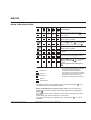
alarm indications table
17
!
!
+–
18
19
20
status or action producing
the indication
21
■ inverter start-up phase prior to load
transfer. The "inverter on" button 22 has
been pressed.
■ normal operation;
■ load supplied by Comet.
bip...bip...
bip...bip...
bip...bip...
■ inverter 7 shutdown following pressing of
the "inverter off" button 23 or a major fault;
■ load supplied via the "static bypass" 3 .
■ operation on battery power;
■ load supplied by Comet.
■ end of battery power or battery should be
checked (1).
bip...bip...
■ minor fault:
load continues to be supplied via inverter.
■ inverter 7 shut down;
■ input power switch 1 is in "off" position;
■ battery circuit breaker 4 is in "off"
position;
■ load supplied via the "static bypass"
3 .
Legend of alarm indications table:
buzzer off,
light off,
bip...bip...
buzzer on,
(1): for standard replacement of batteries, a
technician certified by MGE UPS
SYSTEMS is required to update the
parameters of the new battery so that the
user continues to benefit from the "Battery
Monitoring" function used to see the
available or remaining battery autonomy.
light on,
light flashing
Any state other than normal operation (green "load protected" light 21 on) is
considered a fault by the diagnostics system.
Before undertaking any servicing or other action, note the status of the
different lights and the number(s) of the fault(s) indicated on the diagnostics
display 27 .
If the "Monitor Plus" option is installed, note as well the messages in the list on
the screen.
Certain faults may result in the display not functioning.
If the load still functions, it is supplied via the "static bypass" 3 , i.e. it is not
protected.
Merlin Gerin by MGE UPS SYSTEMS
Comet installation and user manual: E-6761200XT/FA
7.1
alarms (cont')
35
31
33
34
37
16
41
39
61
63
62
65
32
21
22
25
71
72
73
51
T°
11
12
13
14
15
17
18
Fig. 23
■ "11" - battery circuit breaker in "off" position:
indicates that the battery circuit is open (battery circuit breaker 4 is in "off"
position). The load is no longer protected because battery power is no longer
available in the event of an AC input power failure. In the case of the "battery-free
frequency converter" option, it is normal for the "11" message to remain on;
■ "12" - check battery: indicates that the battery should be checked (see Battery
maintenance in the Maintenance and servicing section);
■ "13" - low battery shutdown warning: indicates that battery power will end
after a user-set time period. The user must take the required measures to secure
the load (load shedding, file saving and system shutdown, etc.);
■ "14" - end of battery power;
■ "15" - battery fault: indicates a problem with the battery (see "battery
maintenance" in the "maintenance and servicing" section;
■ "16" - ambient T° fault: this display indicates that the ambient temperature is
outside the tolerance range (<0°C or > 40°C);
■ "17" - battery periodic test: this message indicates that the battery is in the
process of being checked;
■ "18" - battery manual test: this message indicates that the battery is in the
process of being completely discharged in order to update the battery monitoring
parameters;
■ "21" - inverter fault: indicates a fault in the inverter module 7 ; contact the
after-sales support department;
■ "22" - inverter overtemperature: indicates overheating inside the UPS; check
that the Comet ventilation system is working and that the ambient temperature is
within tolerances (see "appendices");
■ "25" - inverter overload: indicates an overload when the load is being
supplied via the inverter. Reduce the load;
■ "31" - Mains 2 voltage outside tolerance range: this display indicates that
the Mains 2 power supply voltage of the "static bypass" 3 is outside the
tolerance range;
7.2
Comet installation and user manual: E-6761200XT/FA
Merlin Gerin by MGE UPS SYSTEMS
■ "32" - phase shift outside tolerance range: this display indicates that the
phase between the Mains 2 power supply of the "static bypass" 3 and the
"inverter module" 7 is outside the tolerance range;
■ "33" - phase sequence fault: informs the user that the phase sequence of the
three-phase power supply is incorrect;
■ "34" - frequency of Mains 2 power supply to "static bypass" 3 outside
tolerances: the output inverter voltage is no more synchronised with Mains 2.
load transfers may be carried out using the following procedure: press, for 3
seconds, simultaneously the security button 26 and:
■ the green "inverter on" button 22 to force transfer of the load to the inverter
7 . Transfer results in a 0.5 second break in the supply of power to the load,
■ the grey "inverter off" button 23 to force transfer of the load to the "static
bypass" 3 . Transfer results in a 0.5 second break in the supply of power to the
load;
■ "35" - "static bypass" overload: indicates an overload when the load is being
supplied via the "static bypass". Reduce the load;
■ "37" - Mains 1 voltage outside tolerance range: this display indicates that
the voltage of the Mains 1 power supply of the "rectifier module" 2 is outside
the tolerance range;
■ "39" - installation fault: indicates an incorrect connection at the frequency
converter input; check the connection of the Mains 1 input source to terminal
block XR1;
■ "41" - load supplied via "static bypass" 3 (normal condition for certain
configurations): this display indicates that the load is powered by the Mains 2 via
the "static bypass" 3 ;
■ "51" - charger fault: indicates a fault in the charger module 6 ; contact the
after-sales support department;
■ "61" - rectifier or chopper fault: indicates a fault in the rectifier module 2 ;
contact the after-sales support department;
■ "62" - chopper overtemperature: see fault "22";
■ "63" - fuses blown on Mains 1 input: indicates that one or more fuses have
blown in the rectifier module 2 ; contact the after-sales support department;
■ "65" - chopper overload: indicates that the active power consumed is too
high. Reduce the load;
■ "71" - internal communication fault: indicates a Comet internal fault; contact
the after-sales support department;
■ "72" - internal communication self-test fault: see fault "71";
■ "73" - CPU board self-test fault: see fault "71".
manual bypass
■ if the load is no longer supplied, a manual bypass operation enabling supply
is possible, while waiting for the after-sales support personnel;
■ proceed as follows:
■ turn off the input power switch 1 ,
■ switch the battery circuit breaker 4 to "off" position,
■ check that all lights are off,
■ turn the "manual bypass" switch 8 as indicated in figure 24 from the
"NORMAL" position to the "BYPASS" position.
Merlin Gerin by MGE UPS SYSTEMS
Comet installation and user manual: E-6761200XT/FA
7.3
alarms (cont')
"Manual bypass" switch
TEST 1
NORMAL
BY-PASS
TEST 2
Fig. 24
Note:
The TEST 1 and TEST 2 positions are reserved for the after-sales support
personnel. Leave the switch set to the "BYPASS" position until the arrival
of the after-sales support personnel.
Use of the switch other than as indicated above may damage Comet and
render void the warranty.
This function is not available for frequency converters.
7.4
Comet installation and user manual: E-6761200XT/FA
Merlin Gerin by MGE UPS SYSTEMS
communication
standard functions
The communication connector 15 , positioned on the back for Comet series 11
and series 31 5/7.5/10/15/20kVA and on the front for the other models, supplies
the following information:
■ operation on the "static bypass";
■ low battery shutdown warning;
■ load supplied by the inverter;
■ operation on battery power.
This connector enables communication with the most common computer systems
(AS400, NOVELL, etc.).
Figure 25 indicates the pin-outs for the SUB-D 15-pin female connector (front
view).
SUB-D 15-pin connector connection
very low safety
voltage signals:
PIJO PC board
5
NO
operation on inverter
8
NF
NO
contact
switching
capacities:
P = 2.5VA
U = 30V max.
I = 0.1A max.
NF
6
operation on
"static bypass"
10
NO
NF
9
operation on battery
connector
SUB-D
15-pin
11
13
NO
NF
7
low battery
shutdown warning
12
14
4
UPS remote
shutdown
(signal between
3 and 15V DC)
Fig. 25
SUB-D 15-pin connector
8
7
6
5
4
3
15 14 13 12 11 10
Merlin Gerin by MGE UPS SYSTEMS
1
2
Note: the remote UPS shutdown
command is valid when the inverter is
supplied by the AC input source or the
battery. The inverter shuts down after
2-minute delay.
9
Comet installation and user manual: E-6761200XT/FA
8.1
communication (cont')
options
Three options may be used simultaneously on Comet, thus enabling
communication with a wide number of computers and control devices.
Monitor Plus (1)
Mini terminal for control and display of AC input power and system parameters.
Can be installed locally or remotely.
Contact 5
This option offers communication of five different signals via dry relay contacts:
■ operation on battery;
■ operation on "static bypass";
■ low battery shutdown warning;
■ load supplied by the inverter;
■ general alarm;
Relay-contact breaking capacities: 250V AC, 125V DC, 1A.
U-TALK (1)
This option manages an RS232 serial interface using an ASCII protocol. This
option is supplied with the CD-ROM "Solution Pac"™ which integrates a range of
management software for MGE UPS SYSTEMS Uninterruptible Power Supply
under SNMP.
JBUS / RS232 and JBUS / RS485 (1)
These options enable remote monitoring of Comet.
BatiBUS
This option provides a link between Comet and a BatiBUS network.
(1): these options can be used with the battery monitoring function which provides
information on:
■ available battery power during normal operation;
■ remaining battery power during operation on battery power.
8.2
Comet installation and user manual: E-6761200XT/FA
Merlin Gerin by MGE UPS SYSTEMS
maintenance and servicing
Preventative maintenance for the Comet is limited to the strict minimum.
However, the list below indicates important procedures to ensure continuous and
correct operation.
safety reminder
Danger: high voltages are present in the Comet system. Any servicing requiring
removal of the protection covers may be undertaken only by qualified personnel
certified by MGE UPS SYSTEMS.
preventive maintenance by user
visual check
■ check the installation and operating conditions:
■ distance from wall,
■ ventilation inlet and outlet vents free,
■ operating temperature, particularly for the batteries;
■ no faults signalled by the lights.
maintenance by the local representative certified by MGE UPS SYSTEMS
Consult the after-sales support department for further information concerning the
services presented below requiring special tools, in particular the "Soft Tunor"
software.
battery maintenance
Battery status is monitored by Comet. When the orange "operation on battery"
light 20 flashes and fault number "12" is indicated on the diagnostics display 27,
the battery should be checked.
When the red "load not protected" light 18 flashes and fault number "15" is
indicated on the diagnostics display 27 , a battery fault is present.
To clear these alarms, press the "security" 26 and "fault reset" 25 buttons at
the same time.
Caution: clearing the alarms in this way disables the battery monitoring and
backup time calculation functions (Monitor Plus option); contact the aftersales support department to check the condition of the battery and replace
it if necessary. The after-sales support technician will reactivate the battery
monitoring and backup time calculation functions.
environmental protection
The battery cells contain substances which are dangerous for the environment.
Following replacement, the after-sales support department forwards old batteries
to special organizations for recycling and disposal.
Merlin Gerin by MGE UPS SYSTEMS
Comet installation and user manual: E-6761200XT/FA
9.1
maintenance and servicing (cont')
annual check
This complete check-up can be run only by qualified personnel certified by
MGE UPS SYSTEMS.
customer training
Training courses offered by MGE UPS SYSTEMS enable personnel to monitor
the system and undertake basic maintenance.
Contact your MGE UPS SYSTEMS distributor for the list of courses offered.
maintenance contracts
Your MGE UPS SYSTEMS contact can supply you with the catalogue of
maintenance contracts that indicate out how you can transfer responsibility for
maintenance to qualified technicians always on call.
9.2
Comet installation and user manual: E-6761200XT/FA
Merlin Gerin by MGE UPS SYSTEMS
options
extended battery cabinet
As standard equipment, Comet comes with a battery providing a backup time (at
full rated load and a power factor of 0.6) of 8 minutes for the 5 kVA Comet S11
and S31 and 10 minutes for the other Comet models. This time can be increased
by installing 1 or 2 additional battery cabinets.
If Comet was not factory-set for the additional cabinets, the new configuration
must be entered by a MGE UPS SYSTEMS after-sales support technician.
additional battery cell characterisitics
Battery cells for an overall operating range of 30 mn
(at rated output power with a power factor of 0.6):
Comet
series 11
series 31
series 33
Battery cell
characterisitics
height (mm)
rated output of device (kVA)
5
7,5
10
15
730
910
910
width (mm)
depth (mm)
360
420
weight (kg)
72
118
149
height (mm)
width (mm)
depth (mm)
weight (kg)
height (mm)
width (mm)
depth (mm)
730
360
420
72
910
400
550
118
910
400
550
149
1085
460
680
176
400
550
weight (kg)
20
30
1085
560
680
270
1085
560
680
1085
560
680
340
1385
610
780
1385
610
780
270
355
480
20
30
400
550
Battery cells for an overall operating range of 50 mn
(at rated output power with a power factor of 0.6):
Comet
series 11
series 31
series 33
Merlin Gerin by MGE UPS SYSTEMS
Battery cell
characterisitics
height (mm)
rated output of device (kVA)
5
7,5
10
15
730
910
910
width (mm)
360
400
400
depth (mm)
420
550
550
weight (kg)
height (mm)
width (mm)
depth (mm)
weight (kg)
115
730
360
420
115
215
910
400
550
215
276
910
400
550
276
1085
2 x 560
680
2 x 270
1085
2 x 560
680
2 x 340
1085
460
680
281
1085
2 x 560
680
2 x 270
1385
2 x 610
780
2 x 355
height (mm)
width (mm)
depth (mm)
weight (kg)
Comet installation and user manual: E-6761200XT/FA
1385
2 x 610
780
2 x 480
10.1
options (cont')
connection of an additional battery cabinet
Prior to any operations, check that the protection devices are in the following
positions:
■ upstream circuit breaker off;
■ input power switch 1 off;
■ battery circuit breaker 4 off;
■ "manual bypass" switch set to the "NORMAL" position.
■ position the battery cabinet on the right side of Comet;
■ connect the terminal block in the battery cabinet to the XR3 terminal block in
Comet as follows:
■ yellow/green cable (earth) to the yellow/green terminal on XR3,
■ red cable (+ pole) to the L+ terminal on XR3,
■ blue cable (– pole) to the L– terminal on XR3;
■ position the two enclosures with the front panels aligned;
■ turn on the circuit breaker in the battery cabinet.
Connection of an additional battery cabinet
Comet connection terminal blocks
(except for 5 kVA Comet S11 or S31)
XR1
Mains
XR3
battery
battery cabinet terminal block
XR2
load
L L+
connection terminal blocks of Comet S11/S31 5kVA
L L+
XR3
battery
10.2
XR3
emergency
off
XR1
Mains 2
(optional)
Comet installation and user manual: E-6761200XT/FA
XR3
battery
L L+
to a second
battery cabinet
(if applicable)
tie the shielding of the
cable to the stud
provided on the
connection cover panel
(see appendices).
Merlin Gerin by MGE UPS SYSTEMS
emergency off
Installation of an emergency off function must be carried out in compliance with
applicable regulations. When an external emergency off function is activated, the
AC input to Comet must be cut to ensure protection of life and property.
However, this action does not cut the supply of power to the load protected by
Comet because the system continues to operate on battery power.
To power down the entire installation via an emergency off function, the action
must also turn off the following via a single device:
■ the battery circuit breaker 4 ;
■ the circuit breaker for the additional battery cabinet(s), if applicable;
■ and a circuit breaker placed downstream of the UPS, otherwise the UPS output
remains live for approximately 3 seconds after the emergency off function has
been activated.
This requires installation of an MX shunt trip.
shunt trip connection
■ check that the upstream circuit breaker on the low voltage switchboard is in "off"
position;
■ check that the input power switch 1 and the battery circuit breaker 4 are in
"off" position;
■ remove the connection cover panel 13 from the Comet;
■ supply the shunt trip coil with AC power across terminals 1 and 4;
■ terminals 2 and 3 may be used to supply (using a voltage identical to that of the
shunt trip) lights indicating the position of the battery circuit breaker 4 (breaking
capacity of contacts is 1300VA);
■ once the connections are made, reposition the connection cover panel.
Connection diagram for MX shunt trip to terminal block XR3
Comet
1
4
2
3
emergency
off button
Ph
N
220 to 240V
50/60Hz
Comet XR3
terminal block
(exept Comet S11
/ S31 of 5kVA)
battery
L– L+
emergency
off
1234
N
circuit
breaker
on light
N
circuit
breaker
off light
1234
XR1/XR3
terminal block
for Comet
S11 / S31
of 5kVA
XR1
XR3
XR3
battery emerg. off Mains 2 (optional)
secure the shielding of the cable to the stud
provided on the connection cover panel (see
appendices).
Merlin Gerin by MGE UPS SYSTEMS
Comet installation and user manual: E-6761200XT/FA
10.3
options (cont')
full galvanic isolation transformer (standard Comet equipment)
This option is required to achieve a downstream neutral system different from the
upstream neutral system. The transformer, installed in a cubicle of the same
design as the Comet cubicle, must be positioned:
■ between the low voltage switchboard and the input power switch for Comet
series 11 and series 33 (see figure 26);
■ between the Comet load output terminals and the load for Comet series 31
(see figure 27).
power connection diagrams
The cables requiring connection are indicated as bold lines.
For information on cable cross-sections, see the "appendices": "selection of cable
cross-sections" (the connection cable between Comet and the option is supplied).
Comet series 11/33
LV
switchboard
CB1
XR4
TR2
XR5
XR1
XR2
load
transformer
Fig. 26
LV
switchboard
CB1
Comet series 31
XR1
XR2 XR4
TR2
transformer
XR5
load
Fig. 27
10.4
Comet installation and user manual: E-6761200XT/FA
Merlin Gerin by MGE UPS SYSTEMS
separate Mains 2 transformer (AC bypass input)
This option can be used to connect the "static bypass" 3 to a second AC input
circuit, if the two AC input come from different sources or if they are fitted with
separate protective devices.
This requires installation of the optional "separate Mains 2 galvanic isolation
transformer".
power connection diagram
The cables requiring connection are indicated as bold lines.
For information on cable cross-sections, see the "appendices": "selection of cable
cross-sections" (the connection cable between Comet and the option is supplied).
LV
switchboard
CB2
Comet
XR4
transformer
CB1
XR5 Mains 2 XR1
filter
Mains 1
XR1
XR2
load
This option comprises a high-frequency filter which limits the disturbances
transmitted to the AC input power supply and guarantees compatibility with the
standards in force. This guarantee is no longer provided if the transformer is used
on its own (without a filter).
Note: for a 5 kVA Comet S11 or S31, the shielding of the Mains 2 cable must be
secured to the stud provided on the connection cover panel (see appendices).
Merlin Gerin by MGE UPS SYSTEMS
Comet installation and user manual: E-6761200XT/FA
10.5
options (cont')
frequency converter
This option can be used to obtain different input and output frequencies. The
frequency converter is supplied with a separate Mains 2.
This option is delivered either with or without a battery.
power connection diagram
The cables requiring connection are indicated as bold lines.
For information on cable cross-sections, see the Appendices (selection of cable
cross-sections).
Comet
LV
switchboard
Mains 2
XR1
Mains 1
XR1
connect nothing to
this terminal block
CB1
XR2
load
10.6
Comet installation and user manual: E-6761200XT/FA
Merlin Gerin by MGE UPS SYSTEMS
hot standby system
This option increases the reliability of the power supply to the load. It requires a
special configuration of the main Comet (with separate Mains 2).
For the "separate Mains 2" option on the standby Comet, see the "separate
Mains 2" section above.
power connection diagram
The cables requiring connection are indicated as bold lines.
For information on cable cross-sections, see the "appendices": "selection of cable
cross-sections" (the connection cables between Comet and the option are
supplied).
LV
switchboard
CB2
standby Comet
XR1
XR5 Mains 2
XR2 XR4
transformer filter
XR1
Mains 2
Comet
CB1
Mains 1
XR1
XR2
load
Merlin Gerin by MGE UPS SYSTEMS
Comet installation and user manual: E-6761200XT/FA
10.7
options (cont')
harmonics filter
It is possible to install a harmonics filter between the AC input power source and
Comet in order to reduce the level of current harmonics absorbed by the source.
This option is available only for Comet series 31 and series 33 units with a rated
output at least equal to 15kVA.
power connection diagram
The cables requiring connection are indicated as bold lines.
For information on cable cross-sections, see the "appendices": "selection of cable
cross-sections" (the connection cables between Comet and the option are
supplied).
Comet
LV
switchboard
XR8 Mains 2 XR1
XR6
filter
XR7 Mains 1 XR1
XR2
load
filter
This option comprises a high-frequency filter which limits the disturbances
transmitted to the AC input power supply.
10.8
Comet installation and user manual: E-6761200XT/FA
Merlin Gerin by MGE UPS SYSTEMS
combined options
full isolation transformer and separate Mains 2 transformer
To implement a power supply via a separate Mains 2 and isolation of Comet from
Mains 1, the two options, full isolation transformer and separate Mains 2
transformer, must be combined. Each option requires its own cubicle.
Comet
LV
switchboard
D2
XR4
XR5
XR1
Mains 2
D1
XR4
XR5
XR1
Mains 1
full isolation transformer and harmonics filter
Example of a Comet series 31
The two options are supplied in the same cubicle:
XR4
XR5
LV
switchboard
D1
load
Comet
XR6
XR8
XR1
Mains 2
XR2
load
XR7
Merlin Gerin by MGE UPS SYSTEMS
Comet installation and user manual: E-6761200XT/FA
XR1
Mains 1
10.9
options (cont')
Example of a Comet series 33
The two options are supplied in the same cubicle. Connection between XR5 and
XR6 is inside the cubicle:
LV switchboard
D1
XR4
XR5
Comet
XR8
XR1
Mains 2
XR7
XR1
Mains 1
XR6
separate Mains 2 transformer and harmonics filter
The two options are supplied in the same cubicle:
LV switchboard
Comet
D2
XR4
XR5
D1
XR6
XR8
XR7
XR1
Mains 2
XR1
Mains 1
No connections are to be made to terminal block XR8.
relative positions of the various cubicles
If several option cubicles are combined, they must be placed to the right of the
UPS cubicle in the following order (from left to right):
■ battery cabinet(s);
■ harmonics filter cubicle (with transformer where applicable);
■ separate Mains 2 isolation transformer cubicle;
■ full galvanic isolation transformer cubicle.
10.10
Comet installation and user manual: E-6761200XT/FA
Merlin Gerin by MGE UPS SYSTEMS
appendices
general characteristics
■
■
■
■
■
the Comet range is made up of three types of uninterruptible power supplies:
Comet series 11 (single-phase input, single-phase output),
Comet series 31 (three-phase + neutral input, single-phase output),
Comet series 33 (three-phase + neutral input, three-phase + neutral output);
each UPS may be configured in a number of manners via a special interface
14 .
On the following pages, standard configuration parameters are indicated in bold
type.
A modification in the configuration requires on-site servicing by the after-sales
support department;
■ except where indicated, the data provided are typical values corresponding to:
■ a rated single-phase voltage of 230V and a rated three-phase voltage of 400V,
■ a linear rated load with a power factor of 0.8.
range characteristics
■ standards
■ design:
■ product:
■ safety:
■ protection:
■ electromagnetic compatibility:
■ environment conditions
■ ambient temperature (1):
■ relative humidity (%):
■ maximum altitude without derating:
■ configuration
■ low battery shutdown warning (minutes):
■ inverter start-up:
■ battery charger:
■ transfer to bypass outside tolerances:
■ frequency converter:
■ colour
■ standard:
CEI 146
EN 50091
CEI 950
CEI 529 (IP 215)
CEI 801
EN 55011
EN 55022
EN 50091-2
< 25°C recommended
0 to 30°C permanent
35°C up to 24 hours
40°C up to 8 hours
0 to 95
< 1000m
1, 2, 3, 4, 5, ...20
automatic or manual
internal or external
yes / no
yes / no
RAL 9002
(1): for a 5 kVA Comet S11 or S31, see the "overload" section.
Merlin Gerin by MGE UPS SYSTEMS
Comet installation and user manual: E-6761200XT/FB
11.1
appendices (cont')
Comet series 11 general characteristics
■ apparent power (kVA):
5
4
91
445
7.5
6
91
668
10
8
91
890
45
50
46
53
46
53
■ at rated load (power factor 0.6):
■ maximum leakage current (mA):
8
10
10
■ directly earthed neutral system (TT):
10
28
23
60
23
60
730
360
420
90
910
400
550
190
910
400
550
210
■ active power (kW):
■ efficiency (%):
■ heat losses (W):
■ noise level (dBa):
■ on RL load:
■ on RCD load:
■ battery backup time (minutes):
■ during a fault with an impedent neutral system:
■ dimensions and weight
■ height (mm):
■ width (mm):
■ depth (mm):
■ weight (kg):
■ AC input
■ number of phases:
■ voltage (V):
■ frequency (Hz):
■ power factor:
■ current distortion (%):
■ inrush current:
■ AC output
■ number of phases:
■ voltage (V):
■ voltage tolerance (%):
■ frequency (Hz):
■ frequency tolerance (free-running) (%):
■ frequency tolerance (synchronized) (%):
■ synchronization rate (Hz/s):
11.2
Comet installation and user manual: E-6761200XT/FB
1
187 to 257
47 to 63
> 0.99
<5
<3
< In
<3
1
220 / 230 / 240
±1
50 / 60
± 0.1
± 1 / ± 1.5 / ± 2 / ± 3 / ± 4
1/2
Merlin Gerin by MGE UPS SYSTEMS
Comet series 31 general characteristics
■ apparent power (kVA):
■ active power (kW):
■ efficiency (%):
■ heat losses (W):
■ noise level (dBa):
■ on RL load:
■ on RCD load:
■ battery backup time (minutes):
■ at rated load (power factor 0.6):
5
4
91
445
7.5
6
91
668
10
8
91
890
15
12
92
1335
20
16
92
1780
45
50
46
53
46
53
50
53
8
10
10
10
10
5
23
11
45
11
45
24
102
24
102
730
360
420
90
910
400
550
190
910
400
550
210
1085
560
680
390
1085
560
680
450
50
53
■ maximum leakage current (mA):
■ directly earthed neutral system (TT):
■ during a fault with an impedent neutral system:
■ dimensions and weight
■ height (mm):
■ width (mm):
■ depth (mm):
■ weight (kg):
■ AC input
■ number of phases:
■ voltage (V):
■ frequency (Hz):
■ power factor:
■ current distortion (%):
■ inrush current:
■ AC output
■ number of phases:
■ voltage (V):
■ voltage tolerance (%):
■ frequency (Hz):
■ frequency tolerance (free-running) (%):
■ frequency tolerance (synchronized) (%):
■ synchronization rate (Hz/s):
Merlin Gerin by MGE UPS SYSTEMS
Comet installation and user manual: E-6761200XT/FB
3
323 to 444
47 to 63
> 0.95
< 26
< In
1
220 / 230 / 240
±1
50 / 60
± 0.1
± 1 / ± 1.5 / ± 2 / ± 3 / ± 4
1/2
11.3
appendices (cont')
Comet series 33 general characteristics
■ apparent power (kVA):
■ active power (kW):
■ efficiency (%):
■ heat losses (W):
■ noise level (dBa):
■ on RL load:
■ on RCD load:
■ battery backup time (minutes):
■ at rated load (power factor 0.6):
10
8
92
890
15
12
92
1335
20
16
92
1780
30
24
92
2670
51
52
51
52
51
52
51
52
10
10
10
10
23
90
23
90
23
250
23
250
1085
460
680
275
1085
460
680
350
1385
610
780
510
1385
610
780
600
■ maximum leakage current (mA):
■ directly earthed neutral system (TT):
■ during a fault with an impedent neutral system:
■ dimensions and weight
■ height (mm):
■ width (mm):
■ depth (mm):
■ weight (kg):
■ AC input
■ number of phases:
■ voltage (V):
■ frequency (Hz):
■ power factor:
■ current distortion (%):
■ inrush current:
3
323 to 444
47 to 63
> 0.95
< 26
< In
■ AC output
■ number of phases:
■ voltage (V):
■ voltage tolerance (%):
■ frequency (Hz):
■ frequency tolerance (free-running) (%):
■ frequency tolerance (synchronized) (%):
■ synchronization rate (Hz/s):
11.4
Comet installation and user manual: E-6761200XT/FB
3
380 / 400 / 415
±1
50 / 60
± 0.1
± 1 / ± 1.5 / ± 2 / ± 3 / ± 4
1/2
Merlin Gerin by MGE UPS SYSTEMS
selection of cable cross-sections
The cross-section of cables depends on:
■ current levels (temperature rise);
■ permissible line voltage drop (3% for AC circuits, 1% for battery circuits);
■ installation (cable rack, troughs, etc.).
Consult the applicable standards to determine the minimum cross-sections for the
desired currents.
Each of the above parameters, for a given type of Comet, is important in
determining the minimum permissible cross-sections.
When confronted with several possibilities, always select the larger value. Cables
must be flexible type.
The currents indicated below are maximum values given for minimum voltages:
Comet
series 11
series 31 (1)
series 33 (2)
Comet
rated output
(kVA)
absorbed line currents (A)
AC input
AC output
current (XR1)
current (XR2)
battery option
(XR3)
5
7.5
26
40
23
35
30
48
10
52
46
46
5
23 (9)
23
30
7.5
35 (14)
35
48
10
46 (18)
46
46
15
20
69 (27)
91 (36)
69
91
76
75
10
18 (26)
15 (26)
46
15
27 (40)
23 (40)
76
20
36 (52)
30 (52)
75
30
54 (78)
45 (78)
112
Note 1: when a "separate Mains 2" option is installed on Comet series 31 for the AC
bypass input, the values in parentheses correspond to Mains 1 line currents and the others
to Mains 2 line currents.
Note 2: for Comet series 33, during operation on the "static bypass" at rated output for a
non-linear load, the values in parentheses correspond to the current in the AC input line
neutral.
For connections to the AC input power supply and to the load, Comet terminal
blocks accept the following cable cross-sectional areas:
Comet rated output
cross-sectional areas (mm2)
(kVA)
flexible cables
rigid cables
series 11 and 5
series 31
7.5 and 10
0 to 4
0 to 10
0 to 6
0 to 16
series 31
15 and 20
16 to 35
16 to 35
series 33
10 and 15
6 to 16
6 to 25
20 and 30
16 to 35
16 to 35
Comet
Merlin Gerin by MGE UPS SYSTEMS
Comet installation and user manual: E-6761200XT/FB
11.5
appendices (cont')
selection of protection devices
Selection of protection devices installed upstream (CB1) or downstream (CB2)
from Comet depends on:
■ the rated line current;
■ the required breaking capacity.
Schematic diagram for protection devices
CB2
LV switchboard
CB1
Comet
CB2
To ensure discrimination during overloads or short-circuits, the following
protection devices are recommended:
Comet
Comet rated
output (kVA)
Merlin Gerin
circuit breaker CB1
Merlin Gerin
circuit breaker CB2
series 11
5
C60N 32A (curve D)
C60L ≤ 6A (curve Z)
7.5
C60N 40A (curve D)
C60N ≤ 10A (curve B)
10
C60N 63A (curve D)
C60N ≤ 10A (curve B)
5
C60N 25A (curve D)
C60L ≤ 6A (curve Z)
7.5
C60N 40A (curve D)
C60N ≤ 10A (curve B)
10
C60N 50A (curve D)
C60N ≤ 10A (curve B)
15
NC100H 80A (curve D)
C60N ≤ 25A (curve B)
20
NC100H 100A (curve D)
C60N ≤ 25A (curve B)
10
C60N 40A (curve D)
C60L ≤ 6A (curve Z)
or C60N ≤ 6A (curve B)
15
C60N 40A (curve D)
C60L ≤ 6A (curve Z)
or C60N ≤ 5A (curve B)
20
C60N 63A (curve D)
C60L ≤ 16A (curve Z)
or C60N ≤ 10A (curve B)
30
NC100H 80A (curve D)
C60L ≤ 16A (curve Z)
or C60N ≤ 10A (curve B)
series 31
series 33
Note:
The breaking capacity of the protection devices must be greater than the
prospective short-circuit current.
Consult the Merlin Gerin Low Voltage Application Guide for further details.
Selection of the trip units for the circuit breakers installed upstream of the
transformers must take the inrush currents (10 to 14In) into account.
11.6
Comet installation and user manual: E-6761200XT/FB
Merlin Gerin by MGE UPS SYSTEMS
If the configuration includes the "separate Mains 2" option, the protection devices
recommended for Mains 1 and Mains 2 are the same as those of circuit breaker
CB1 in the table above for Comet series 11 and Comet series 33.
For Comet series 31, the recommended protection devices are given in the table
below:
Schematic diagram for protection devices ("separate Mains 2" option)
CB2
LV switchboard
CB1'
Mains 2
CB1
Mains 1
Comet
CB2
Comet
Comet rated
output (kVA)
Merlin Gerin
circuit breaker CB1
(Mains 1)
Merlin Gerin
circuit breaker CB1'
(Mains 2)
series 31
5
C60N 10A (curve D)
C60N 25A (curve D)
7,5
C60N 16A (curve D)
C60N 40A (curve D)
10
15
C60N 20A (curve D)
C60N 32A (curve D)
C60N 50A (curve D)
NC100H 80A (curve D)
20
C60N 40A (curve D)
NC100H 100A (curve D)
Note:
The breaking capacity of the protection devices must be greater than the
prospective short-circuit current.
Consult the Merlin Gerin Low Voltage Application Guide for further details.
Selection of the trip units for the circuit breakers installed upstream of the
transformers must take the inrush currents (10 to 14In) into account.
Merlin Gerin by MGE UPS SYSTEMS
Comet installation and user manual: E-6761200XT/FB
11.7
appendices (cont')
connection of the cable shielding
The battery, emergency off and Mains 2 cables of 5 kVA Comet S11 or S31
UPSs must be shielded. This shielding musts be secured to the studs provided on
the connection cover panel, on the back of the UPS (see figure 2).
Each connection must be made as follows (see figure below):
■ introduce the cable wires into the cylinder and keep the cable shielding outside
the cylinder,
■ tie the cable shielding to the cylinder, behind its shouldered part,
■ connect the wires to the corresponding terminal block,
■ put the connection cover panel back into place and secure it with screws,
■ tie the cable(s) to the lower angle bracket of the connection cover panel and to
the vertical angle bracket of the other connection cover panel with mains 1 cable
and the load cable.
connection cover panel
shielding cylinders
tie
cable shielding
connection cable
ties
cable shielding
protective cover (removed)
connection cover panel
11.8
Comet installation and user manual: E-6761200XT/FB
Merlin Gerin by MGE UPS SYSTEMS
glossary
forced shutdown: user-initiated shutdown of the inverter due to incorrect AC
input (Mains 1 or Mains 2) characteristics and resulting in a 0.5 second
interruption in the supply of power.
backup time: the duration over which Comet can supply full rated load without
AC input power. This time depends on the battery.
battery: a number of electrolytic cells connected together to supply electrical
power. The cell electrodes operate in a liquid or gel type electrolyte.
"static bypass": power electronics equipment for switching from one power
source to another without an interruption in supply. Example: transfer from
inverter to bypass line or back.
manual bypass: manual switch enabling supply of power to the load directly
from AC input power during maintenance or servicing.
cubicle: enclosure housing Comet constituent parts (rectifier, charger, inverter,
"static bypass", battery, etc.).
charger: device supplying the battery with DC power to recharge and/or maintain
the battery at the rated charge level.
transfer to inverter: load switching from the "static bypass" to the inverter.
transfer to bypass: load switching from the inverter to the "static bypass".
battery circuit breaker: DC-power circuit breaker that protects the battery circuit
(fused switch for 5 kVA Comet S11 or S31).
low battery shutdown warning: signal indicating the upcoming end of battery
power and the resulting inverter shutdown and interruption in the supply of power
to the load.
powered down: no power is present on Comet circuits (battery circuit breaker
off, upstream circuit breaker off).
rated current In: rated current supplied by Comet (power factor 0.8).
input power switch: switching device installed at Comet input and enabling
rectifier shutdown.
forced operation: user-initiated connection of the load to the inverter with a 0.5
second interruption in the supply of power.
inverter: module that transforms input DC power into a virtually perfect sine wave
(regulated, no-break current).
rated output Pn: apparent power Pn supplied by Comet under given load
conditions (power factor 0.8).
output Pu: apparent power Pu supplied by Comet under given load conditions. It
is less than or equal to the rated output Pn. The ratio Pu/Pn defines the Comet
load level.
rectifier: device drawing from the power required by Comet from the AC input
source. The AC input power is transformed (rectified) into DC power.
Mains 1 (AC input power): primary source of power for the rectifier and the
inverter.
Merlin Gerin by MGE UPS SYSTEMS
Comet installation and user manual: E-6761200XT/FA
12.1
glossary (cont')
Mains 2 (AC bypass input power): source of power for the load in the event of
an inverter shutdown.
overload: power drawn by the load in excess of the Comet rated output.
LV switchboard: low voltage switchboard upstream from Comet.
transfer: load switching from "static bypass" to the inverter or vice versa.
load: all devices connected to Comet output terminals.
load protected: load is supplied via the inverter, i.e. with battery protection.
load not protected: load is supplied via the "static bypass", i.e. without battery
protection.
12.2
Comet installation and user manual: E-6761200XT/FA
Merlin Gerin by MGE UPS SYSTEMS
Merlin Gerin by MGE UPS SYSTEMS
- 6761200XT -
As standard, specifications and designs change
from time to time, please ask for confirmation of
the information given in this publication.
MGE UPS SYSTEMS S.A.
7, Chemin du vieux chêne
ZIRST 4202
38942 Meylan Cedex
FRANCE
Product names mentioned herein may be
trademarks and registred trademarks of their
respective companies.
MGE UPS SYSTEMS S.A. designs, manufactures
and markets Merlin Gerin brand UPSs.
6761200XT/FC
This document is printed on environment-friendly
paper.
Internet: www.mgeups.com
Published by MGE UPS SYSTEMS - 02/99