1
R
EN
TMX-R705
Mobile Overhead Monitor
FR
• OWNER'S MANUAL
Please read before using this equipment.
ES
• MODE D'EMPLOI
Veuillez lire avant d’utiliser cet appareil.
• MANUAL DE OPERACIÓN
Léalo antes de utilizar este equipo.
ALPINE ELECTRONICS, INC.
Tokyo office: 1-1-8 Nishi Gotanda,
Shinagawa-ku,
Tokyo 141-8501, Japan
Tel.: (03) 3494-1101
ALPINE ELECTRONICS OF AMERICA, INC.
19145 Gramercy Place, Torrance,
California 90501, U.S.A.
Tel.: 1-800-ALPINE-1 (1-800-257-4631)
ALPINE ELECTRONICS OF CANADA, INC.
Suite 203, 7300 Warden Ave. Markham,
Ontario L3R 9Z6, Canada
Tel.: 1-800-ALPINE-1 (1-800-257-4631)
Sankei Kikaku Co., Ltd.
1-13-38, Hinodai, Hino, Tokyo, Japan
ALPINE ELECTRONICS OF AUSTRALIA PTY. LTD.
6-8 Fiveways Boulevarde Keysborough,
Victoria 3173, Australia
Tel.: (03) 9769-0000
ALPINE ELECTRONICS GmbH
Kreuzerkamp 7-11 40878 Ratingen, Germany
Tel.: 02102-45 50
ALPINE ITALIA S.p.A.
Via C. Colombo 8, 20090 Trezzano Sul Naviglio
MI, Italy
Tel.: 02-48 47 81
ALPINE ELECTRONICS FRANCE S.A.R.L.
(RCS PONTOISE B 338 101 280)
98, Rue De La Belle Etoile, Z.I. Paris Nord Il
B.P. 50016 F-95945, Roissy, Charles De Gaulle
Cedex, France
Tel.: 01-48 63 89 89
ALPINE ELECTRONICS OF U.K., LTD.
13 Tanners Drive, Blakelands, Milton Keynes
MK14 5BU, U.K.
Tel.: 01908-61 15 56
ALPINE ELECTRONICS DE ESPAÑA, S.A.
Portal De Gamarra 36, Pabellón 32
01013 Vitoria (Alava)-Apdo. 133, Spain
Tel.: 34-45-283588
Designed by ALPINE Japan
Printed in Japan (S)
68P41262Y72-O
ENGLISH
Contents
Operating Instructions
WARNING
WARNING .................................................. 2
CAUTION ................................................... 3
PRECAUTIONS ......................................... 3
Basic Operations
Information
In Case of Difficulty ........................................ 12
Specifications ................................................... 12
Installation and Connections
Warning ............................................................ 13
Caution ............................................................. 13
Precautions ....................................................... 14
Parts Names of the Overhead Monitor .............. 4
Mounting Instruction ....................................... 15
Opening the Monitor Display ............................ 5
Connections ..................................................... 16
FR
Closing the Monitor Display .............................. 5
Adjusting the Monitor Viewing Angle ............... 6
LIMITED WARRANTY
Adjusting the Volume ........................................ 6
Audio Mute Function ......................................... 6
Switching the Source ......................................... 6
ES
Switching Display Modes .................................. 7
Other Useful Features
Adjusting Brightness of Picture ......................... 8
Adjusting Color Density of Picture ................... 8
Adjusting Tint of Picture .................................... 8
DE
Setting the Brightness of the Backlight ............. 8
Adjusting the Lowest Level of the Backlight .... 9
Setting Automatic Closing of Monitor ............... 9
Dome Light Settings ........................................ 10
Battery Replacement ................................... 11
IT
Replacing the Dome Light Bulb .................. 11
SE
1-EN
WARNING
WARNING
This symbol means important instructions.
Failure to heed them can result in serious
injury or death.
DO NOT OPERATE ANY FUNCTION THAT TAKES
YOUR ATTENTION AWAY FROM SAFELY DRIVING
YOUR VEHICLE.
Any function that requires your prolonged attention
should only be performed after coming to a complete stop.
Always stop the vehicle in a safe location before
performing these functions. Failure to do so may result in
an accident.
KEEP THE VOLUME AT A LEVEL WHERE YOU CAN
STILL HEAR OUTSIDE NOISE WHILE DRIVING.
Failure to do so may result in an accident.
MINIMIZE DISPLAY VIEWING WHILE DRIVING.
Viewing the display may distract the driver from looking
ahead of the vehicle and cause an accident.
DO NOT DISASSEMBLE OR ALTER.
Doing so may result in an accident, fire or electric shock.
USE THIS PRODUCT FOR MOBILE 12V APPLICATIONS.
Use for other than its designed application may result in
fire, electric shock or other injury.
KEEP SMALL OBJECTS SUCH AS BATTERY OUT OF
THE REACH OF CHILDREN.
Swallowing them may result in serious injury. If
swallowed, consult a physician immediately.
DO NOT PLACE HANDS, FINGERS OR FOREIGN
OBJECTS IN INSERTION SLOTS OR GAPS.
Doing so may result in personal injury or damage to the
product.
USE THE CORRECT AMPERE RATING WHEN
REPLACING FUSES.
Failure to do so may result in fire or electric shock.
2-EN
DO NOT BLOCK VENTS OR RADIATOR PANELS.
Doing so may cause heat to build up inside and may result
in fire.
DO NOT WATCH VIDEO WHILE DRIVING.
Watching the video may distract the driver from looking
ahead of the vehicle and cause an accident.
INSTALL THE PRODUCT CORRECTLY SO THAT THE
DRIVER CANNOT WATCH TV/VIDEO UNLESS THE
VEHICLE IS STOPPED AND THE EMERGENCY BRAKE
IS APPLIED.
It is dangerous (and illegal in many states) for the driver
to watch the TV/Video while driving the vehicle. The
driver may be distracted from looking ahead and an
accident could occur. If the product is not installed
correctly, the driver will be able to watch the TV/Video
while driving the vehicle and may be distracted from
looking ahead causing an accident. The driver or other
people could be severely injured.
CAUTION
This symbol means important instructions.
Failure to heed them can result in injury or
material property damage.
HALT USE IMMEDIATELY IF A PROBLEM APPEARS.
Failure to do so may cause personal injury or damage to
the product. Return it to your authorized Alpine dealer or
the nearest Alpine Service Center for repairing.
KEEP FINGERS AWAY WHILE THE MOTORIZED
FRONT PANEL OR MOVING MONITOR IS IN
PRECAUTIONS
Temperature
Be sure the temperature inside the vehicle is between
+45°C (+113°F) and 0°C (+32°F) before turning your unit
on.
Fuse Replacement
When replacing the fuse(s), the replacement must be of
the same amperage as shown on the fuse holder. If the
fuse(s) blows more than once, carefully check all
electrical connections for shorted circuitry. Also have your
vehicle’s voltage regulator checked.
FR
MOTION.
Failure to do so may result in personal injury or damage
to the product.
DO NOT MIX NEW BATTERIES WITH OLD
BATTERIES. INSERT WITH THE CORRECT BATTERY
POLARITY.
When inserting the batteries, be sure to observe proper
polarity (+ and –) as instructed.
Rupture or chemical leakage from the battery may cause
fire or personal injury.
Maintenance
If you have problems, do not attempt to repair the unit
yourself. Return it to your Alpine dealer or the nearest
Alpine Service Station for servicing.
Installation Location
Make sure the TMX-R705 will not be exposed to:
• Direct sun and heat
• Excessive dust
• High humidity
• Excessive vibrations
• After turning the system off, a slight ghost of the image
will remain temporarily. This is an effect peculiar to
LCD technology and is normal.
• Under cold temperature conditions, the screen may
lose contrast temporarily. After a short warm-up
period, it will return to normal.
ES
DE
Dome Light Bulb Replacement Precautions
When replacing the dome light bulb, replace with one
having the specified 12V, 5W capacity.
Use of a different capacity bulb may cause damage to the
unit.
Note that damage under such circumstances will not be
covered by the warranty.
IT
To the customers using wireless headphones (sold
separately)
If you turn ACC or power source of the monitor off while
you are listening with wireless headphones, a big noise
occurs through the headphones. So, be sure to take
wireless headphones off your ears before you turn ACC or
power source of the monitor off.
To the customers using wired headphones (sold
separately)
When you use the wired headphones with this unit, it is
recommended to use the ones of impedance of 24 – 45
ohms.
3-EN
SE
Basic Operations
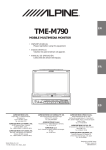
Parts Names of the Overhead Monitor
Remote Sensor
Monitor Display
OPEN/CLOSE Button
Dome Light
Monitor Display Panel
Wireless Headphone Transmitter
Headphone Outputs
Two output jacks (mini-phono plug)
are provided for wired headphones.
Output level is adjusted using the
Volume UP/DN buttons on the remote
control.
NOTE
Plugging a headphone into either
jack will mute the Variable Audio Output.
RESET Switch
Immediately after installing or applying
power to the unit, it should be initialized.
Using a pencil or other pointed object,
press this RESET switch to complete the
initialization procedure.
4-EN
An SPST (Single-Pole, Single-Throw) switch (sold
separately) can be added to simplify this procedure.
Then, you can simply place it in the OFF position
when you leave the vehicle. Turn the SPST switch
back ON before using the TMX-R705. For connecting
the SPST switch, refer to the Installation.
• After turning the system off, a slight ghost of the
image will remain temporarily. This is an effect
peculiar to LCD technology and is normal.
• Under cold temperature conditions, the screen may
lose contrast temporarily. After a short warm-up
period, it will return to normal.
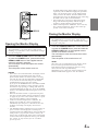
Closing the Monitor Display
Opening the Monitor Display
NOTE
The TMX-R705 is a precision device. With careful
handling, its performance can be maintained at a high
level for a long time.
1
Press the OPEN/CLOSE button of the main unit
or press the POWER button, press and hold the
OPEN/CLOSE button of the supplied remote
control for at least 2 seconds.
The unit beeps 3 times and opens the monitor
automatically.
Then the power of the monitor turns on.
NOTES
• Since this is an overhead monitor, the display will be
lowered when opened and raised when closed.
If the monitor touches an obstacle while it is being
lowered, the unit will stop immediately. Should this
occur, remove the obstacle and press the OPEN/
CLOSE button again to close the monitor.
If you press the POWER button or the OPEN/CLOSE
button while the monitor is being opened or closed,
the monitor stops opening or closing and cannot be
closed automatically. In this case, press the POWER
button or the OPEN/CLOSE button again to close the
monitor.
• When the movable monitor is opened, do not place
any object on the monitor and be careful not to bump
or apply any pressure to the monitor while it is open.
This can cause damage to the mechanism.
• Under low ambient temperature conditions, the
display may be dark for a short period of time
immediately after the power is turned on. Once the
LCD has warmed up, the display will return to
normal.
• The TMX-R705 draws minimal current even when its
power switch is turned off. If the switched power
(ignition) lead of the TMX-R705 is connected directly
to the positive (+) post of the vehicle's battery, the
battery may be discharged. If this lead is unswitched,
it must be disconnected from the battery post should
the vehicle be left unused for an extended
period of time.
1
NOTE
The TMX-R705 is a precision device. With careful
handling, its performance can be maintained at a high
level for a long time.
FR
Press the OPEN/CLOSE button of the main unit
or press the POWER button, press and hold the
OPEN/CLOSE button of the supplied remote
control for at least 2 seconds.
The unit beeps 3 times and closes the monitor
automatically.
Then the power of the monitor turns off.
ES
NOTE
Since this is an overhead monitor, the display will be
lowered when opened and raised when closed.
If the monitor touches an obstacle while it is being
raised, the unit will stop immediately.
Should this occur, remove the obstacle and press the
OPEN/CLOSE button again to close the monitor.
DE
IT
SE
5-EN
Basic Operations
Adjusting the Volume
1
Press the
or
button to adjust the volume.
NOTE
The volume changes continuously if the
or
button is held down. This operation will affect the
headphone and External Audio outputs only. The
IR signal for the wireless headphones are not
affected.
Audio Mute Function
Activating this function will instantly lower the
volume level by 20 dB.
Adjusting the Monitor Viewing
Angle
1
Adjust the monitor's angle for better visibility.
9
2
While viewing the screen that is shown press the
ANGLE 9 or 8 button to adjust the display to the
ideal viewing angle.
The display viewing angle can be adjusted
between about 80 and 105 degrees.
Press the
or
button to adjust the right-left
viewing angle. It is possible to adjust the display
viewing angle up to about 15 degrees to the left
or right.
Press and hold the OPEN/CLOSE button of the
main unit for at least 2 second. This will return
the monitor quickly to its center viewing position.
9
9
NOTES
• The angle changes continuously if the ANGLE 9 and
8 buttons or the and buttons are held down.
• If there are any obstructions to the monitor when
adjusting the angle, first remove the obstruction and
then readjust the angle.
• The screen color will vary when viewed at certain
angles. Adjust the screen angle for the best viewing
position.
• If the voltage of the vehicle's battery power is low,
the screen may blink when the screen angle is
changed. This is normal and not a malfunction.
• The adjusted angle is stored in the memory.
6-EN
Switching the Source
1
Press the SOURCE button. Each press of the
button will switch through the modes as follows:
AUX1
AUX2
9
1
Press the MUTE button to activate the MUTE
mode. The audio level will decrease by about 20
dB.
Pressing the MUTE button again will bring the
audio back to its previous level.
NOTES
• If nothing is connected to AUX 1 or AUX 2, raising
the volume while these inputs are selected, may result
in excessive noise.
• In addition to the Remote Control Source button,
each AUX input has its own wired select trigger. This
is called the External AV Select (Pink/Blue) wire.
• The External AV Select trigger is a pulsed signal
(Active Low, 500ms or more). If this input is remains
low, switching to other sources is not possible
(Switching sources using the Remote Control is still
possible). This is useful if you don’t want an AV
source to be interrupted. Playing a video is a good
example of this scenario. This function is mainly
used for connecting with other ALPINE products.
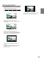
Switching Display Modes
1
Press the DISPLAY button or press and hold the
SETUP button for at least 2 seconds. Each press
changes the display modes as follows:
MODE 1
(WIDE)
MODE 2
(ZOOM)
MODE 3
(CINEMA)
MODE 4
(NORMAL)
MODE 4 (NORMAL)
A normal television broadcasting (4:3) image is
displayed in the center (normal image).
FR
MODE 1 (WIDE)
Stretches the normal image evenly in a
horizontal direction so that it is displayed on the
entire screen.
ES
MODE 2 (ZOOM)
Stretches the normal image evenly in a
horizontal direction so that it is displayed on the
entire screen. The stretching ratio increases the
closer to the left or right edge of the screen.
DE
IT
MODE 3 (CINEMA)
Stretches the normal image horizontally and
vertically.
The top and bottom of the screen is cut slightly
to adapt it to a cinema size image with a
proportion of 16:9.
SE
7-EN
Other Useful Features
Adjusting Tint of Picture
Press the 9 or 8 button within 10 seconds and
select TINT.
Press the
or
adjust the tint.
9
3
Press the SETUP button.
button within 10 seconds to
9
1
2
SET UP
AUX1
BRIGHT
COLOR
TINT
PAGE 1
0
0
0
R
4
G
Press the SETUP button to finish adjustments.
Adjusting Brightness of Picture
Press the
or
button within 10 seconds to
adjust the brightness.
SET UP
AUX1
PAGE 1
BRIGHT
COLOR
TINT
0
0
0
MIN
Press the SETUP button to finish adjustments.
Adjusting Color Density of Picture
Press the 9 or 8 button within 10 seconds and
select COLOR.
9
3
Press the SETUP button.
Press the
or
button within 10 seconds to
adjust the color density.
9
1
2
The brightness of the LCD panel’s backlighting is
adjustable to more closely match the vehicle’s
interior lighting. This makes the screen easier to
view.
1
2
3
Press the SETUP button.
Press the 9 or 8 button within 10 seconds and
select DIMMER.
Press the
the value.
or
9
4
MAX
Setting the Brightness of the
Backlight
button within 10 seconds to set
9
Press the 9 or 8 button within 10 seconds and
select BRIGHT.
9
3
Press the SETUP button.
9
1
2
AUTO:
The screen brightness will dim when the headlight
switch is turned on (if proper connections are
made).
HIGH:
Maximum screen brightness.
LOW:
The preset screen brightness that was set when
adjusting the minimum backlight level.
SET UP
AUX1
BRIGHT
COLOR
TINT
–
SET UP
PAGE 1
AUX1
0
0
0
PAGE 2
DIMMER AUTO
DIMMER Lv. AT CLOSE OFF
+
AUTO HIGH LOW
4
Press the SETUP button to finish adjustments.
8-EN
4
Press the SETUP button to finish adjustments.
The minimum brightness level for the
backlighting (LOW) is adjustable. This is used to
match the screen brightness to the dashboard
(especially at night). This setting is recalled
whenever the vehicle’s headlight switch is turned
on in the AUTO Dimmer mode.
Press the 9 or 8 button within 10 seconds and
select DIMMER Lv.
or
button within 10 seconds to set
9
Press the
the value.
9
3
Press the SETUP button.
SET UP
AUX1
PAGE 2
DIMMER AUTO
DIMMER Lv. AT CLOSE OFF
LOW
4
HIGH
Simply turn the ignition key to OFF to
automatically close the monitor display.
1
2
3
Press the SETUP button.
Press the 9 or 8 button within 10 seconds to
select AT CLOSE.
Press the
the value.
or
9
1
2
Setting Automatic Closing of
Monitor
button within 10 seconds to set
9
Adjusting the Lowest Level of the
Backlight
AUTO:
Automatic closing of the display in depending upon
whether the ignition switch is ON or OFF.
If you press the POWER button or the OPEN/
CLOSE button while the monitor is being opened or
closed, the monitor stops opening or closing, even if
AUTO setting is on, and cannot be closed
automatically.
In this case, press the POWER button or the OPEN/
CLOSE button again to close the monitor.
FR
ES
Press the SETUP button to finish adjustments.
OFF:
Manual closing of the display.
SET UP
AUX1
PAGE 2
DIMMER AUTO
DIMMER Lv. AT CLOSE OFF
DE
AUTO OFF
4
Press the SETUP button to finish adjustments.
IT
SE
9-EN
Other Useful Features
Dome Light Settings
1
Press the DOME LIGHT button to turn the Dome
Light ON or OFF regardless of whether the
vehicle's doors are open or closed.
Door Closed: The dome light will remain lit until
the vehicle's door is opened and
closed. The dome light will return
to Auto mode. To switch OFF the
dome light manually, press the
DOME LIGHT button again.
Door Open: The dome light will remain OFF
until the vehicle's door is closed
and re-opened. The dome light will
return to Auto mode.
To switch ON the dome light
manually, press the DOME LIGHT
button again.
• With the dome light ON and the vehicle's door
OPEN, press and hold the DOME LIGHT button
for at least 3 seconds. The dome light will be
switched OFF permanently regardless of the
opening and closing of the vehicle's doors. To
cancel, with the vehicle's door open, press and
hold the DOME LIGHT button for at least 3
seconds.
NOTE
If the Override button is connected, it will always work
regardless of the Remote Dome Light Status.
10-EN
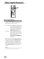
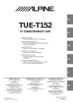
Battery Replacement
Replacing the Dome Light Bulb
Applicable battery: Use two “AAA” sized dry
batteries or equivalent.
• Point the remote control transmitter toward the
remote sensor on the TMX-R705 and use the
remote control within 2 meters from the TMXR705.
1
Opening the battery cover.
Slide out the battery cover while firmly pressing
in the direction of arrow.
NOTE
When replacing the dome light bulb, replace with one
of the specified 12V, 5W capacity. Use of a different
capacity bulb may cause damage to the unit. Please
note that no guarantee is carried out if this is the
case.
1
2
3
4
5
2
Use 12V, 5W rated bulb (End Cap Base: T8 x 28)
available at any autoparts store or consult your
authorized Alpine Mobile Multimedia dealer for
further information.
Use a flat-bladed screwdriver to release the
hooks and open the lense, being careful not to
scratch the product.
Pry at two recessed points at rear of lense.
FR
Be careful not to crack the lense.
Change the bad bulb and press the lense back in
place.
4 Hooks
Lense
4 Hooks
Replacing the battery.
Put the batteries in the case observing the
polarities as illustrated.
ES
DE
3
Closing the cover.
Push the cover as illustrated until a click is heard.
IT
SE
11-EN
Information
In Case of Difficulty
If you encounter a problem, please review the items in
the following checklist. This guide will help you isolate
the problem if the unit is at fault. Otherwise, make sure
the rest of your system is properly connected or consult
your authorized Alpine dealer.
No function or display.
• Car's ignition is off.
- Turn the ignition on.
• No fuse or blown fuse.
- Check the cause and replace the fuse.
• Incorrect connections.
- Check connection and remedy.
• Vehicle's battery is weak.
- Check the voltage of vehicle's battery.
Unclear picture display.
• Fluorescent tube is exhausted.
- Replace the fluorescent tube.*
No picture display.
• Brightness control is set for minimum brightness control.
- Adjust the brightness.
• Incorrect setting of the VCR mode.
- Switch to the correct mode.
• Protective circuit is on because of high temperature.
- Wait until the temperature inside the vehicle comes
down to the operating temperature range (45°C).
Picture color is poor.
• Brightness/Color/Tint control are not set to the proper
positions.
- Check each control.
Spots or dotted lines/stripes appear.
• Caused by neon signs, high-voltage power lines, CB
transmitter, other vehicle's ignition plugs, etc.
- Change the location of your vehicle.
The display angle cannot be adjusted or the
adjustment screen does not appear.
• Mechanism error.
- Press the OPEN/CLOSE button to stow away the
display, and raise the display again.
Noise is picked up by the Wireless Headphone
(available separately) or the sound is inaudible.
• Wireless Headphone is being used in a place exposed to
direct sunlight.
- Use in an environment that is not exposed to direct
sunlight.
• Wireless Headphone batteries are exhausted.
- Replace the batteries.
* The fluorescent tube replacement is not free of charge
even within the warranty period, for the tube is an article
of consumption.
12-EN
Specifications
MONITOR SECTION
Screen Size
LCD Type
Operation System
Number of Picture Elements
Effective Number of
Picture Elements
Illumination System
7.0"
Transparent type TN LCD
TFT active matrix
336,960 pcs. (1,440 x 234)
99.99% or more
Cold cathode
fluorescent tube
GENERAL
Power Requirement
Operating temperature
Weight
14.4V DC (11-15 V allowable)
+32ºF to +113ºF (0ºC to + 45ºC)
2.0 kg (4 lbs. 7 oz)
DIMENSIONS
Width
Height
Depth
228 mm (8-15/16")
55 mm (2-3/16")
267mm (10-1/2")
NOTES
• Due to continuous product improvement, specifications
and design are subject to change without notice.
• The LCD panel is manufactured using an extremely high
precision manufacturing technology. Its effective pixel
ratio is over 99.99%. This means that there is a possibility
that 0.01% of the pixels could be either always ON or
OFF.
Installation and Connections
Before installing or connecting the unit, please
read the following and pages 2 and 3 of this
manual thoroughly for proper use.
Warning
DO NOT INSTALL THE MONITOR NEAR THE
PASSENGER SEAT AIR BAG.
If the unit is not installed correctly the air bag may not
function correctly and when triggered the air bag may
cause the monitor to spring upwards causing an accident
and injuries.
MAKE THE CORRECT CONNECTIONS.
Failure to make the proper connections may result in fire
or product damage.
USE ONLY IN CARS WITH A 12 VOLT NEGATIVE
GROUND.
(Check with your dealer if you are not sure.) Failure to do
so may result in fire, etc.
BEFORE WIRING, DISCONNECT THE CABLE FROM
THE NEGATIVE BATTERY TERMINAL.
Failure to do so may result in electric shock or injury due
to electrical shorts.
DO NOT ALLOW CABLES TO BECOME ENTANGLED
IN SURROUNDING OBJECTS.
Arrange wiring and cables in compliance with the manual
to prevent obstructions when driving. Cables or wiring
that obstruct or hang up on places such as the steering
wheel, gear lever, brake pedals, etc. can be extremely
hazardous.
Caution
HAVE THE WIRING AND INSTALLATION DONE BY
EXPERTS.
The wiring and installation of this unit requires special
technical skill and experience. To ensure safety, always
contact the dealer where you purchased this product to
have the work done.
USE SPECIFIED ACCESSORY PARTS AND INSTALL
THEM SECURELY.
DO NOT SPLICE INTO ELECTRICAL CABLES.
Be sure to use only the specified accessory parts. Use of
other than designated parts may damage this unit
internally or may not securely install the unit in place.
This may cause parts to become loose resulting in hazards
or product failure.
Never cut away cable insulation to supply power to other
equipment. Doing so will exceed the current carrying
capacity of the wire and result in fire or electric shock.
ARRANGE THE WIRING SO IT IS NOT CRIMPED OR
PINCHED BY A SHARP METAL EDGE.
DO NOT USE BOLTS OR NUTS IN THE BRAKE OR
STEERING SYSTEMS TO MAKE GROUND
CONNECTIONS.
Bolts or nuts used for the brake or steering systems (or
any other safety-related system), or tanks should NEVER
be used for installations or ground connections. Using
such parts could disable control of the vehicle and cause
fire etc.
KEEP SMALL OBJECTS SUCH AS BATTERIES OUT
OF THE REACH OF CHILDREN.
FR
Route the cables and wiring away from moving parts (like
the seat rails) or sharp or pointed edges. This will prevent
crimping and damage to the wiring. If wiring passes
through a hole in metal, use a rubber grommet to prevent
the wire’s insulation from being cut by the metal edge of
the hole.
DO NOT INSTALL IN LOCATIONS WITH HIGH
MOISTURE OR DUST.
Avoid installing the unit in locations with high incidence
of moisture or dust. Moisture or dust that penetrates into
this unit may result in product failure.
ES
DE
IT
Swallowing them may result in serious injury. If
swallowed, consult a physician immediately.
DO NOT INSTALL IN LOCATIONS WHICH MIGHT
HINDER VEHICLE OPERATION, SUCH AS THE
STEERING WHEEL OR GEARSHIFT.
SE
Doing so may obstruct forward vision or hamper
movement etc. and results in serious accident.
13-EN
Installation and Connections
Precautions
IMPORTANT
• Be sure to disconnect the cable from the (–) battery
post before installing your TMX-R705. This will
reduce any chance of damage to the unit in case of a
short-circuit.
• Be sure to connect the color coded leads according to
the diagram. Incorrect connections may cause the unit
to malfunction or damage the vehicle's electrical
system.
• When making connections to the car’s electrical
system, be aware of the factory installed components
(e.g. on-board computer). Do not tap into these leads to
provide power for this unit. When connecting the
TMX-R705 to the fuse box, make sure the fuse for the
intended circuit of the TMX-R705 has the appropriate
amperage. Failure to do so may result in damage to the
unit and/or the vehicle. When in doubt, consult your
ALPINE dealer.
• The TMX-R705 uses female RCA-type jacks for
connection to other units (e.g. amplifier) having RCA
connectors. You may need an adaptor to connect other
units. If so, please contact your authorized ALPINE
dealer for assistance.
Please record the serial number of your unit in
the space provided below and keep it as a
permanent record. The serial number plate is
located on the bottom of the unit.
14-EN
SERIAL NUMBER:
INSTALLATION DATE:
INSTALLATION TECHNICIAN:
PLACE OF PURCHASE:
Mounting Instruction
This Motorized Overhead Monitor requires a 12V
DC power supply for the Monitor Display to open
and close.
Please DO NOT OPEN and CLOSE BY HAND and
handle it with care.
Please follow these steps carefully!
1
Remove the transportation screw from the unit.
4
After opening the monitor display and
adjusting the viewing angle, move the battery
line off before installing the unit.
5
Use 4 screws and attach to the mounting
plate.
(Screw holes are hidden under the panel.
Therefore, the panel has to be opened.)
(Two rear side screw holes are located under
the mechanism cover plate.)
After installing the unit, reconnect the battery
line which you moved off before.
Transportation Screw
Screws
2
Connect the main power connector (8-pin
connector) as well as one of the AUX input,
mini-DIN to RCA Interface connectors (refer to
“Installation and Connections” on page 16).
Also, refer to the same page showing 5m miniDIN Extension Cable (to AUX-IN 1 connector)
for further details. Make the proper Battery,
ACC (ignition) and Ground connections to
make the unit operational.
Screws
FR
Console
If you have any problem for the installation,
please contact to ALPINE Tech Support.
3-1 Turn the unit upside down. With both hands
hold the edges of this unit so as not to interfere
with the opening and closing the monitor.
Open the monitor according to the following
procedure. (Two persons may be needed.)
1) Press the OPEN/CLOSE button of this unit,
or press the POWER button, press and hold
the OPEN/CLOSE button of the supplied
remote control for at least 2 seconds. The
monitor will automatically open and close
with each press.
ES
DE
IT
NOTES
• Do not forcibly open or close the monitor. Doing so
will cause damage.
• The monitor cannot be opened or closed unless the
unit is turned upside down.
3-2 Use the supplied remote control to adjust the
view angle of the monitor as required.
(See Page 6 “Adjusting the Monitor Viewing
Angle”)
SE
NOTE
Do not forcibly change the view angle of the monitor.
Doing so may cause damage.
15-EN
Installation and Connections
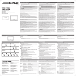
Connections
Common Ground (Black)
Left Positive (Blue)
Audio/Video
output
connector
AUX-IN 1
connector
AUX-IN 2
connector
5m Mini-DIN Extension Cable
5m Mini-DIN Extension Cable
To other
monitor
Connect to the cable
of the vehicle side
Right Positive (Green)
(Rear View)
Dome Light-Always OFF (Gray/Green) 1
p
5
9
Dome Light-Always ON (Red/Green)
Accessory/Ignition (Red)
q
GND (Black)
w
Ext. A/V Select (Pink/Blue)
e
Mini-DIN to RCA Interface
Mini-DIN to RCA Interface
Dome Light-Door (Blue/Green)
q
GND (Black)
Ext. A/V Select (Pink/Blue)
IR Remote Out (White/Brown)
Battery (Yellow)
r
For Front
Monitor
(Sold Separately)
For Front
Monitor
Tune Box
(IVA-C801 etc.)
Ai-NET
Connector
To AUX Input
(AUX 1)
i
To Audio/Video
Output Terminals
Remote Out Aux 1
(White/Brown)
i
To Audio/Video
Output
o
VPE-V180A
(Sold Separately)
u
y
Remote IN
(White/Brown)
DVD Changer
(Sold Separately)
Ai-NET
Connector
16-EN
7
t
r
Video Game
Console
(Sold Separately)
Dome Light
Rocker switch is
located on Alpine
overhead console
To AUX Output
To AUX Input (AUX 2)
To Audio/Video
Output Terminals
6
3
8
IR Remote Out (White/Brown)
t
4
Dome Light Battery (Yellow/Green)
w
e
2
2
3
Remote Turn-on (Blue/White)
Accessory/Ignition (Red)
1
w
GND (Black)
1 Dome Override (Always OFF) (Gray/Green)
Connecting to Pin #1 of the external dome light
SW. When it is grounded, the Dome light remains
off all the time.
2 Dome Override (Always ON) (Red/Green)
Connect to Pin #3 of the external dome light SW.
When it is grounded, the Dome light remains on
all the time.
3 Dome Light (Door Trigger) (Blue/Green)
This is a constant + 12V for the main unit. It is
recommended that separate connections from
the Dome light battery line are used to avoid
noise and over-current.
8 Fuse Holder (5A)
9 KWE-508V (Included)
p KWE-508V (Sold Separately)
Connect to the factory door switch.
NOTES
• Have the switching done being the power cord taken
off.
• Have the switching done accurately. If you make
mistakes in setting, the dome light remains lit, and it
may cause running down of the battery.
• Vehicle Door polarity depending on the vehicle type
can be changed by the "Door SW polarity" where is
located on the left side of the main unit. (Default:
Negative Switched System)
q IGN/ACC (Red)
This wire connects to the ignition or accessory
line of the vehicle. This triggers main power to
turn the unit on. Although both DIN cables have
this wire, only one of them should be connected
to the IGN/ACC line.
NEG
e External AV Select (Pink/Blue)
ES
External AV Select forces the TMX-R705 to
switch to the A/V input sending the AV Select
trigger.
r IR Remote Out (White/Brown)
Positive Switched System
+12V
FR
w GND (Black)
This is the shield GND. It should connect to the
vehicle's chassis for reducing any noise.
POS
DOOR SW POLARITY
7 BATT (Main Unit) (Yellow)
Negative Switched System
GND
GND
+12V
4 Remote Turn ON (Blue/White)
Connecting to other device such as a small
amplifier to turn them ON synchronizing with the
TMX-R705 power ON. It gives +12V when the
power is ON.
5 GND (Black)
This is a common Ground for the main unit and
the Dome light. Another GND line connects to Pin
#2 of the external dome light SW.
6 BATT (Dome Light) (Yellow/Green)
This is a constant +12V for the Dome light.
Connect to the Dome light +12V line on the
vehicle.
The Remote Out wire connects to any ALPINE
Mobile Video product which has an external
remote input function. For example, products
such as a DVD, VCR and TV Tuner.
DE
t AV RCA Connector (Video, Audio R, Audio L)
These RCA-type connectors connect to any
video source. This connector is used as an A/V
input for the TMX-R705, however it may also be
used as an output for other units.
IT
y Remote Control Lead (White/Brown)
u RCA Extension Cable (Included with DVD
changer)
i RCA Extension Cable (Sold Separately)
o Ai-NET Cable (Included with DVD changer)
17-EN
SE
LIMITED WARRANTY
ALPINE ELECTRONICS OF AMERICA, INC. AND ALPINE OF CANADA INC. ("Alpine"), are dedicated to quality
craftsmanship and are pleased to offer this Warranty. We suggest that you read it thoroughly. Should you have any
questions, please contact your Dealer or Alpine at one of the telephone numbers listed below.
● PRODUCTS COVERED:
This Warranty covers Car Audio/Visual Products and
Related Accessories ("the product"). Products purchased in
the Canada are covered only in the Canada. Products
purchased in the U.S.A. are covered only in the U.S.A.
2 You should provide a detailed description of the
problem(s) for which service is required.
3 You must supply proof of your purchase of the product.
4 You must package the product securely to avoid
damage during shipment.
● LENGTH OF WARRANTY:
● HOW WE LIMIT IMPLIED WARRANTIES:
This Warranty is in effect for one year from the date of the
first consumer purchase.
All Alpine Car Audio analog tape heads excluding Video
tape heads are warranted for life against manufacturing
defects causing failure.
ANY IMPLIED WARRANTIES INCLUDING FITNESS FOR
USE AND MERCHANTABILITY ARE LIMITED IN
DURATION TO THE PERIOD OF THE EXPRESS
WARRANTY SET FORTH ABOVE AND NO PERSON IS
AUTHORIZED TO ASSUME FOR ALPINE ANY OTHER
LIABILITY IN CONNECTION WITH THE SALE OF THE
PRODUCT.
● WHO IS COVERED:
● HOW WE EXCLUDE CERTAIN DAMAGES:
This Warranty only covers the original purchaser of the
product, who must reside in the United States, Puerto Rico
or Canada.
ALPINE EXPRESSLY DISCLAIMS LIABILITY FOR
INCIDENTAL AND CONSEQUENTIAL DAMAGES
CAUSED BY THE PRODUCT. THE TERM "INCIDENTAL
DAMAGES" REFERS TO EXPENSES OF
TRANSPORTING THE PRODUCT TO THE ALPINE
SERVICE CENTER, LOSS OF THE ORIGINAL
PURCHASER'S TIME, LOSS OF THE USE OF THE
PRODUCT, BUS FARES, CAR RENTALS OR OTHERS
COSTS RELATING TO THE CARE AND CUSTODY OF
THE PRODUCT. THE TERM "CONSEQUENTIAL
DAMAGES" REFERS TO THE COST OF REPAIRING OR
REPLACING OTHER PROPERTY WHICH IS DAMAGED
WHEN THIS PRODUCT DOES NOT WORK PROPERLY.
THE REMEDIES PROVIDED UNDER THIS WARRANTY
ARE EXCLUSIVE AND IN LIEU OF ALL OTHERS.
● LIFETIME TAPE HEAD WARRANTY:
● WHAT IS COVERED:
This Warranty covers defects in materials or workmanship
(parts and labor) in the product.
● WHAT IS NOT COVERED:
1
This Warranty does not cover the following:
Damage occurring during shipment of the product to
Alpine for repair (claims must be presented to the
carrier).
Damage caused by accident, abuse, negligence,
misuse, improper connections, improper operation or
failure to follow instructions contained in the Owner's
manual.
Damage caused by act of God, including without
limitation, earthquake, fire, flood, storms or other acts of
nature.
Any cost or expense related to the removal or
reinstallation of the product.
Service performed by an unauthorized person, company
or association.
Any product which has the serial number defaced,
altered or removed.
Any product which has been adjusted, altered or
modified without Alpine's consent.
Any product not distributed by Alpine within the United
States, Puerto Rico or Canada.
Any product not purchased from an Authorized Alpine
Dealer.
Any product that has been determined to contain an
excessive amount of dust or dirt and any product that
contains other contaminants including liquid or foreign
objects.
2
3
4
5
6
7
8
9
Ä
● HOW TO OBTAIN WARRANTY SERVICE:
1 You are responsible for delivery of the product to an
● HOW STATE/PROVINCIAL LAW RELATES TO THE
WARRANTY:
This Warranty gives you specific legal rights, and you may
also have other rights which vary form state to state and
province to province. In addition, some states/provinces do
not allow limitations on how long an implied warranty lasts,
and some do not allow the exclusion or limitation of
incidental or consequential damages. Accordingly,
limitations as to these matters contained herein may not
apply to you.
● IN CANADA ONLY:
This Warranty is not valid unless your Alpine car audio
product has been installed in your vehicle by an Authorized
Installation Center, and this warranty stamped upon
installation by the installation center.
● HOW TO CONTACT CUSTOMER SERVICE:
Should the product require service, please call the following
number for your nearest Authorized Alpine Service Center.
U.S.A.
CANADA
1-800-ALPINE-1 (1-800-257-4631)
1-800-ALPINE-1 (1-800-257-4631)
Authorized Alpine Service Center or Alpine for repair
and for payment of any initial shipping charges. Alpine
will, at its option, repair or replace the product with a
new or reconditioned product without charge. If the
repairs are covered by the warranty, and if the product
was shipped to an Authorized Alpine Service Center or
Alpine, Alpine will pay the return shipping charges.
Alpine Electronics of America, Inc., 19145 Gramercy Place, Torrance, California 90501, U.S.A.
Alpine Electronics of Canada, Inc., Suite 203, 7300 Warden Ave. Markham, Ontario, L3R 9Z6, Canada