1
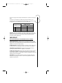
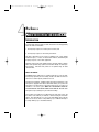
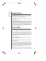
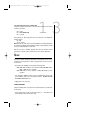
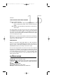
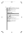
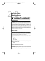
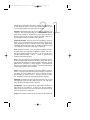
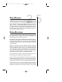
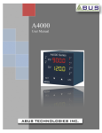
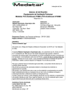
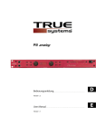
Signal Processors 18-0121-B
6/8/99
10:24 AM
Page 1
C ONTENTS
RTA SERIES II.....................2
8 3 4 / 8 3 5 S E R I E S I I. . . . . . . . . . . . . . . .. . 11
8 4 4 S E R I E S I I . . . . . . . . . . . . . . . . . . . .. . 17
8 6 6 S E R I E S I I . . . . . . . . . . . . . . . . . . . . . .20
1
Signal Processors 18-0121-B
2
6/8/99
10:24 AM
Page 2
CAUTION
RISK OF ELECTRIC SHOCK
DO NOT OPEN
A T T E N T I O N : RISQUE DE CHOC ELECTRIQUE - NE PAS OUVRIR
W A R N I N G : TO REDUCE THE RISK OF FIRE OR ELECTRIC
SHOCK DO NOT EXPOSE THIS EQUIPMENT TO RAIN OR MOISTURE
The symbols shown at left are internationally accepted symbols that warn of potential hazards with electrical products. The lightning flash with arrowpoint in an equilateral triangle means that there are dangerous voltages present within the unit.
The exclamation point in an equilateral triangle indicates that it is necessary for the
user to refer to the owner’s manual.
These symbols warn that there are no user serviceable parts inside the unit. Do not
open the unit. Do not attempt to service the unit yourself. Refer all servicing to
qualified personnel. Opening the chassis for any reason will void the manufacturer’s warranty. Do not get the unit wet. If liquid is spilled on the unit, shut it off
immediately and take it to a dealer for service. Disconnect the unit during storms to
prevent damage.
U.K. MAINS PLUG WARNING
A moulded mains plug that has been cut off from the cord is unsafe. Discard the
mains plug at a suitable disposal facility. NEVER UNDER ANY CIRCUMSTANCES
SHOULD YOU INSERT A DAMAGED OR CUT MAINS PLUG INTO A 13 AMP
POWER SOCKET. Do not use the mains plug without the fuse cover in place.
Replacement fuse covers can be obtained from your local retailer. Replacement
fuses are 13 amps and MUST be ASTA approved to BS1362.
SAFETY INSTRUCTIONS (EUROPEAN)
NOTICE FOR CUSTOMERS IF YOUR UNIT IS EQUIPPED WITH A POWER
CORD.
WARNING: THIS APPLIANCE MUST BE EARTHED.
The cores in the mains lead are coloured in accordance with the following code:
GREEN and YELLOW - Earth
BLUE - Neutral
BROWN - Live
As colours of the cores in the mains lead of this appliance may not correspond with
the coloured markings identifying the terminals in your plug, proceed as follows:
• The core which is coloured green and yellow must be connected to the terminal in the plug marked with the letter E, or with the earth symbol, or
coloured green, or green and yellow.
• The core which is coloured blue must be connected to the terminal marked
N or coloured black.
• The core which is coloured brown must be connected to the terminal marked
L or coloured red.
Signal Processors 18-0121-B
6/8/99
10:24 AM
Page 3
3
These units comply with the European “EMC Directive” for emissions and susceptability
The power cord is terminated in a CEE7/7 plug (Continental Europe). The
green/yellow wire is connected directly to the unit's chassis. If you need to change
the plug, and if you are qualified to do so, refer to the table below.
CONDUCTOR
WIRE COLOR
Normal
Alt
L
LIVE
BROWN
BLACK
N
NEUTRAL
BLUE
E EARTH GND GREEN/YEL
WHITE
GREEN
WARNING: If the ground is defeated, certain fault conditions in the unit or in the
system to which it is connected can result in full line voltage between chassis and
earth ground. Severe injury or death can then result if the chassis and earth
ground are touched simultaneously.
IMPORTANT!
FOR YOUR PROTECTION, PLEASE READ THE FOLLOWING:
WATER AND MOISTURE: Appliance should not be used near water (e.g. near a
bathtub, washbowl, kitchen sink, laundry tub, in a wet basement, or near a swimming pool, etc). Care should be taken so that objects do not fall and liquids are not
spilled into the enclosure through openings.
POWER SOURCES: The appliance should be connected to a power supply only of
the type described in the operating instructions or as marked on the appliance.
GROUNDING OR POLARIZATION: Precautions should be taken so that the
grounding or polarization means of an appliance is not defeated.
POWER CORD PROTECTION: Power supply cords should be routed so that they
are not likely to be walked on or pinched by items placed upon or against them,
paying particular attention to cords at plugs, convenience receptacles, and the point
where they exit from the appliance.
SERVICING: The user should not attempt to service the appliance beyond that
described in the operating instructions. All other servicing should be referred to
qualified service personnel.
Signal Processors 18-0121-B
4
6/8/99
10:24 AM
Page 4
RTA SERIES II
20
25
31.5
40
50
63
80
100
125
160
200
250
315
400
500
630
800
1K 1.25K
1.6K
2K
2.5K
3.15K
4K
5K
6.3K
8K
10K
12.5K
16K
20K
2/6
WINDOW
RES.
PINK
NOISE
3dB
OFF
1dB
ON
1/3
0/0
-1/-3
-2/-6
RTAseriesII
real time audio analyzer
MIN
MAX
PINK
NOISE
MIN
MAX
INPUT
GAIN
CALIBRATED
MICROPHONE
INTRODUCTION
A real-time audio analyzer (RTA) is an audio measurement tool that graphically
shows two kinds of information:
1. The frequency response of an audio system or device, and
2. The frequency response of the listening environment.
This kind of information is very useful for equalizing a P.A. system, finding
feedback hot spots, or "nodes", in reinforcement situations, and flattening the
frequency response of other audio equipment.
RTAs that show both the entire audible frequency spectrum (20 Hz to 20 kHz)
and its entire dynamic range (loudness from 0 dB to 120 dB) are called spectrum analyzers. RTAs that show portions of the dynamic range are called
“window” RTAs.
ABOUT THE DOD RTA
The DOD Electronics RTA Series II is a window-type RTA. It covers the audible frequency spectrum (20 Hz to 20 kHz), and has a five LED level meter for
each of the 31 audio frequency bands that it covers.
The RTA Series II includes a calibrated audio measurement microphone. This
microphone is equipped with a 40 foot cable which enables you to position the
microphone in several locations in the reinforcement area as you make your
evaluations of the audio system. ONLY THIS MICROPHONE SHOULD BE
PLUGGED INTO THE JACK ON THE FRONT OF THE PANEL OF THE RTA. Other
microphones may be damaged or give inaccurate readings.
The sensitivity of the RTA can be modified using the input level control, and
the window of the RTA may be widened or narrowed using the Resolution
switch. This switch allows you to choose the LED display range in dB per
LED. You can choose either a 1 dB per LED step (for a 4 dB wide window) or
a 3 dB per LED step (for a 12 dB wide window).
Signal Processors 18-0121-B
6/8/99
10:24 AM
Page 5
5
The DOD RTA Series II also has its own internal pink noise generator and level
control. Pink noise is defined as an audio signal that contains all frequencies
at equal energy levels. For this reason, pink noise sounds a lot like static.
Pink noise is useful when setting up P.A. systems and audio systems when
you need to see the frequency response of the system.
On the rear of the unit is an auxiliary microphone jack for use with other measurement microphones, and an output jack for the pink noise generator.
When the pink noise is off, this jack acts as an audio output so that the signal
may be looped through the RTA and monitored during a performance. There
is also an input jack that allows you to directly analyze equipment in a system.
FRONT PANEL CONTROLS
Power Switch: Applies power to the RTA.
Display LEDs: Each vertical column of LEDs displays the signal level within
that frequency band. Each frequency is on a 1/3rd octave ISO centered point
from 20 Hz to 20kHz.
Input Level Control: This control sets the input level from the calibrated
microphone input jack, the line level input jack, or the auxiliary microphone
input jack. Use this control to set the response of the display to a useful
range.
Resolution Switch: This push-push switch selects the size of step between
LEDs to either 1 dB or 3 dB. This effectively widens or narrows the window
that the RTA shows, giving you a wider or narrower view of the incoming signal.
Pink Noise Switch: This push-push switch turns the pink noise generator on
or off. To prevent damage to your audio system, be sure to turn down your
audio system’s gain control before turing on the pink noise generator.
Pink Noise Level Control: This rotary potentiometer sets the output level of
the pink noise generator. To prevent damage to your audio system, be sure to
set this control to minimum before turning on the pink noise generator.
Calibrated Microphone Input Jack: This jack supplies power to the calibrated microphone. Plug only the calibrated microphone provided with the RTA
into the jack on the front panel of the RTA. Other microphones may be damaged or give inaccurate readings.
Signal Processors 18-0121-B
6/8/99
10:24 AM
Page 6
6
REAR PANEL CONTROLS
Auxiliary Microphone Input Jack: A female XLR-type connector intended for
use with microphones other than the calibrated microphone provided with the
RTA. This jack accepts low impedance microphones.
Line Input Jack: This is a 1/4-inch phone jack that may be connected to
unbalanced line level sources.
Line Output/Pink Noise Output Jack: A 1/4-inch phone jack that provides
connection to unbalanced line level inputs. Engaging the pink noise switch on
the front panel causes the pink noise generated by the RTA to be output
through this jack. Adjust the level for the pink noise generator with the rotary
potentiometer on the front panel of the RTA. Disengaging the pink noise
switch on the front panel allows this jack to act as a pass-through to the signal introduced at the line input jack.
APPLICATION NOTES
Here are a few important ideas to understand before you use the RTA.
The RTA is measuring device. It does not effect or change the sound. In order
to make the necessary changes of frequency response in an audio system,
you will need to have either a graphic equalizer or parametric equalizer. Since
the RTA measures in 1/3rd octave increments, it is easiest to use a 1/3rd
octave graphic equalizer in the system, such as DOD's 231 Series II, 431
Series II, or 831 Series II.
A parametric equalizer is also useful. Parametric equalizers, however, are not
as easy to use as graphic equalizers.
Note: A lot of “fixing” can be done by simply repositioning the microphones
and speakers in a system.
The RTA will aid you in finding frequency response problems in your audio
system, and, using an equalizer, correct those problems. Making the sound
pleasing begins after you correct the system problems, and is best done by an
experienced ear. “Flat” systems will seem too shrill or bright to the listener in
most reinforcement situations, so the equalizer setting will almost always
change to make the system sound better.
When measuring the sound in an enclosed sound reinforcement application,
use more than one microphone location. This is because speaker dispersion
Signal Processors 18-0121-B
6/8/99
10:24 AM
Page 7
7
characteristics vary greatly as you move around the room (particularly with
multiple driver systems). If you find that different areas of the room behave
differently, try to average the settings on the equalizer to correct the room as
a whole.
You don’t need to blast the system with pink noise. Use just enough level
from the RTA to overcome any ambient room noise (such as air conditioners
or traffic noise). The sensitivity of the RTA should be just high enough that
when you turn the pink noise off, none of the LEDs are lit by the noise in the
room.
Use the 3 dB resolution setting on frequencies below 500 Hz. Peak response
of the pink noise causes drift in the 1 dB resolution setting, making it hard to
correct quickly. Use the 1 dB resolution setting to measure frequencies above
500 Hz.
EQUALIZING THE MAIN SPEAKERS OF A STANDARD REINFORCEMENT SYSTEM
First, place the calibrated microphone 3 to 4 feet in front of the main speakers on the axis of the speaker. This is especially important with an indoor system so that you make the first adjustments to the system inside this critical
distance (before the reverberation of the room environment has a chance to
affect the response of the system).
Turn on the pink noise generator, being careful not to blast the system. Make
sure that you turn down the input to the system, then increase the pink noise
level to a listenable measuring level. Using the graphic equalizer, adjust the
response of the system to be as flat as possible.
Once you have equalized and corrected the system in the near field, move the
calibrated microphone out into the room, a normal listening distance from the
speakers. As you move the microphone away from the speakers, you will
notice two things:
1. The high frequency response of the system will fall off, usually starting at
about 10 kHz.
2. When there are other structures nearby, one or more peaks or dips will
appear in the low end.
The high frequency rolloff is caused by absorption of high frequencies in the
air. Don’t adjust the highs any more by measurement. The highs can be
adjusted by ear using program material you’re familiar with. Be sure to check
Signal Processors 18-0121-B
6/8/99
10:24 AM
Page 8
8
several positions in the room and compromise the equalization/attenuation
setting for the best possible sound. This may be done either with the equalizer or by aiming the tweeters of the main speakers differently.
Low frequency dips and peaks are room-related, and may be corrected to
some extent. Before you make any corrections, be sure to move the calibrated microphone around in the room to get a feel about how position dependent
the peaks and dips may be. When you know where in the room the peaks are,
at what frequencies they occur, and their amplitude, you may attempt to notch
them out with the equalizer.
Finally, play some program material with which you’re familiar and set the system’s response to your taste.
EQUALIZING STAGE MONITORS USING THE RTA
The following procedure is a quick and easy way to minimize feedback in a
monitor system, and to get the best sound from your stage monitors. Place
the calibrated microphone a few inches to the side of the stage microphone.
This is so that the stage microphone doesn’t get in the way of the calibrated
microphone when picking up the stage monitor signal.
Turn on the pink noise generator, being careful not to blast the monitors.
Make sure that you turn down the input to the system, then increase the pink
noise level to a convenient measuring level. Use just enough level from the
RTA to overcome any ambient room noise
Turn up the gain on the stage microphones until they begin to feed back. You
will see the feedback frequency displayed in the RTA window.
If you’re using more than one stage monitor, find the one that feeds back the
worst and use that monitor to find the feedback nodes. Notch out the offending frequency with your equalizer. Increase the gain on the stage microphones until you observe another feedback node. Notch out this frequency.
You may attempt to find and notch out other frequencies, but after the third
frequency, this will become unproductive. You’ll find that in making deep
notches to reduce the feedback, the sound quality of the monitor system is
reduced.
Using pink noise, attempt to flatten the response of the monitors. If you are
trying to achieve the highest possible sound level before feedback from the
stage monitors, the sound quality of the monitor system will be reduced. The
best sound from the monitors is usually obtained with a "compromise setting"
on the equalizer. The goal of this type of setting is to modestly reduce the
feedback nodes, but still allow good sound quality from the monitors.
Signal Processors 18-0121-B
6/8/99
10:24 AM
Page 9
9
Another method for equalizing a monitor system uses the stage microphones without
the RTA’s calibrated microphone. Most reinforcement type microphones are not flat
in their frequency response. This procedure, however, takes the stage microphone’s
response into account as you equalize the system.
Use the system’s own microphones to sample the sound field on stage using the pink
noise generator signal. Have someone stand in front of the microphone or place their
hand in front of the microphone so that you can see what effect it may have on the
system’s feedback and overall sound.
This is the best way to minimize feedback and get the highest sound level from the
monitors, but you will sacrifice some sound quality.
Once you’ve equalized the system with one of the above procedures, the following
setup will help you find the howls and ringing that inevitably occur as you use the system (this procedure can be used for both monitors and mains).
Use a mono or auxiliary output or loop through the RTA to your speakers.
Adjust the level input to the RTA so that the “+” LEDs flash on signal peaks. Set the
resolution of the RTA to the 3 dB range.
After feedback occurs, watch the RTA. The last frequency band to decay is where the
feedback is occurring. This frequency may then be notched out using the equalizer.
Signal Processors 18-0121-B
6/8/99
10:24 AM
10
Page 10
SPECIFICATIONS
Number of Frequency Bands: 31.
Display Range: 1 dB step per LED, or 3 dB step per LED.
Level Range: 53 dB to 107 dB SPL.
Display Attack Time: Peak, Instantaneous.
Frequency Accuracy: ±4%.
Pink Noise: Pseudo-random, digital synthesized.
Pink Noise Level: -26 dBu to -7 dBu.
Calibrated Microphone: Omni-directional, back-electret condenser-type, RTA
powered.
Microphone Sensitivity: -64 dB, ±3 dB (0dB =1V/µbar @ 1kHz).
Microphone Frequency Response: 20 Hz to 20 kHz, ±1 dB.
Auxiliary Microphone Input: XLR-type connector, balanced.
Auxiliary Microphone Impedance: 4 kohms.
Auxiliary Microphone Maximum Gain: 104 dB.
Auxiliary Microphone Minimum Signal: -95 dBu.
Line Level Input: 1/4-inch phone jack, unbalanced.
Line Level Input Impedance: 30 kohms.
Line Level Maximum Gain: 40 dB.
Line Level Minimum Signal: -30 dBu.
Signal Processors 18-0121-B
SERIES
834/835
LOW LEVEL
MID LEVEL
HIGH LEVEL
125
HIGH PASS
834seriesII
stereo crossover
40 Hz
HIGH PASS
375
0
dB
GAIN
+15
-∞
0
dB
-∞
dB
0
-∞
50
0
dB
Hz
.75
LOW LEVEL
11
LOW LEVEL
x10
40 Hz
MID LEVEL
375
0
dB
+15
-∞
0
dB
-∞
LOW-MID
RANGE
LOW / HIGH
FREQUENCY
500
HIGH LEVEL
0
dB
50
-∞
dB
HIGH-MID
HIGH
0
835seriesII
MONO
LOW LEVEL
dB
+15
GAIN
-∞
dB
0
LOW LEVEL
-∞
STEREO
5.6
15
.75
2
kHz
7.5
20
MONO
HIGH-MID/HIGH
FREQUENCY
MONO
STEREO
LOW / HIGH
FREQUENCY
500
HIGH LEVEL
MODE
250
100
dB
1.9
5
x10
RANGE
CHANNEL TWO
GAIN
750
0
RANGE
500
Hz
LOW-MID/HIGH-MID
FREQUENCY
250
MODE
stereo crossover
MID / HIGH
FREQUENCY
3.7 10
LOW / MID
FREQUENCY
250
HIGH LEVEL
125
7.5
kHz
Page 11
CHANNEL TWO
GAIN
HIGH PASS
5.6
CHANNEL ONE
GAIN
II
1.9
RANGE
500
LOW/LOW-MID
FREQUENCY
LOW
10:24 AM
MID / HIGH
FREQUENCY
3.7
LOW / MID
FREQUENCY
250
CHANNEL ONE
GAIN
6/8/99
RANGE
750
1,000
0
x10
LOW / MID
FREQUENCY
0
dB
+15
RANGE
-∞
dB
0
MID LEVEL
-∞
100
dB
1,000
0
HIGH LEVEL
RANGE
x10
MID / HIGH
FREQUENCY
RANGE
MONO
INTRODUCTION
The DOD 834 Series II is a stereo 3-way, mono 4-way crossover, and the 835
Series II is a stereo 2-way, mono 3-way crossover. These high-quality
crossover networks are designed to extract maximum sound quality from
your multi-amped sound system at a price working musicians can afford.
Accurate state-variable, 18 dB/octave Butterworth filters prevent peaks or dips
in the output at crossover points, ensuring good driver protection by rolling
off crossover frequencies rapidly.
A two-pole, high-pass filter may be electronically inserted at 40 Hz using a
switch on the front panel (834 only), and a variable low frequency summed
output is available for mono subwoofer applications.
The rear panel of the 834/835 is clearly labeled for stereo and mono operation, and all outputs on the 834 except the mono Low Frequency Sum output
include phase switches.
ADVANTAGES OF A MULTIPLE AMPLIFIER SYSTEM
Multi-amped systems use separate amplifiers for each frequency band, allowing each amplifier to deliver maximum efficiency within a specified range.
This method of amplification yields a cleaner overall sound and a significant
decrease in the amount of power needed to drive the system to the same levels as a full-range amplified system with more power.
The greatest power demands in a sound system are made by the low frequencies of the program material. This is because music and voice signals
contain mostly low frequency information, and low frequency drivers are generally less efficient than high frequency transducers.
In a multi-amped system, the power amplifier(s) for the low frequencies can
be large enough to handle greater power demands, allowing high frequency
Signal Processors 18-0121-B
6/8/99
10:24 AM
Page 12
12
power amplifiers to be much smaller, yet adequate to handle the demands of
the high frequency content of the program material. Since each element of
the system is driven by its own amplifier, any distortion that occurs is limited
to the frequencies of the overdriving power amplifier. The rest of the signal
remains clear and undistorted.
Also, since lower priced, smaller amplifiers can do the job of the larger and
much more expensive amplifiers needed to drive full-range amped systems,
the cost of a sound system can be significantly reduced (and sound better in
the process). It may also be easier to haul several smaller power amplifiers
around, rather than one big one, making portable systems easier to handle.
INSTALLATION
Install the crossover in a rack using the provided rack screws. Route the AC
power cord away from audio lines and plug into a convenient outlet. Connect
audio lines to the crossover using the appropriate input jacks to channels 1
and 2 (for stereo operation), or to channel 1 only (for mono operation).
Connect the appropriate output jacks for stereo 3-way, mono 4-way operation
(834 only), or stereo 2-way, mono 3-way (835). The rear panel is clearly
marked for proper connection. Follow the top labels for stereo connection or
the bottom labels for mono connection.
All inputs and outputs are balanced. Use XLR type male plugs for inputs and
female plugs for outputs. For balanced operation using 1/4" phone plug connectors, use only tip-ring-sleeve (stereo) jacks. For unbalanced operation
using 1/4" phone plug connectors, use only tip-sleeve (mono) jacks.
FOR BALANCED CONNECTION:
Wire XLR connections as follows:
Pin 2: high
Pin 3: low
Pin 1: ground or common
Wire 1/4" tip-ring-sleeve phone plug connectors as follows:
Tip: high
Ring: low
Sleeve: ground
Signal Processors 18-0121-B
6/8/99
10:24 AM
Page 13
13
FOR UNBALANCED AMPLIFIER CONNECTION:
To make an unbalanced connection to the unit's XLR connectors, wire the line
connectors as follows:
Pin 2: high
Pin 3: NO CONNECTION
Pin 1: ground
Use tip-sleeve 1/4" phone plug connectors for connection to the amplifiers,
wired as follows:
tip: high
sleeve: ground
Note: The 834 1/4" jacks may be connected balanced or unbalanced and that
the 835 has both balanced and unbalanced outputs. Input impedance is 40K
ohms, and output impedance is 102 ohms.
Once the crossover is installed, adjusted, and tested, an optional security
panel may be secured to the front panel of the unit to prevent tampering.
SETUP
Consult your speaker and driver manufacturer's specifications for the recommended crossover frequencies. Basic setup procedures for the crossovers
are as follows:
• Label each power amplifier for its respective frequency band.
834: LOW, MID, or HIGH for stereo operation; LOW, LOW-MID, HIGHMID, or HIGH for mono operation.
835: LOW, HIGH for stereo operation or LOW, MID, HIGH for mono
operation.
• Set each power amplifier volume control at maximum and connect each
power amplifier output to its correct speaker or driver. DO NOT TURN ON
THE POWER AMPLIFIERS YET.
• Apply power to the crossover.
STEREO OPERATION
Using the markings in the top row of the front and rear panels, set each channel as follows:
• Set the gain control to 0 dB. Set all level controls to -∞ and switch in the
40 Hz high-pass filter if desired (834 only).
Signal Processors 18-0121-B
6/8/99
10:25 AM
Page 14
14
•
834: Set the LOW/MID crossover frequency for each channel according
to the front panel markings.
835: Set the LOW/HIGH crossover frequency for each channel according to the front panel markings.
•
834: If the desired frequency is above 500 Hz, the Range switch must
be engaged (LED indicator lit). If the desired frequency is below
500 Hz, the Range switch must be disengaged (LED indicator off).
When the range switch is engaged, the frequencies marked around the
LOW/MID (LOW/HIGH for 835) frequency control are multiplied by ten. In
other words, if the LOW/MID (LOW/HIGH for 835) frequency is set at 250 and
the range switch is engaged, the actual crossover frequency is 2.5 kHz.
•
834: Set the MID/HIGH crossover frequency. The Channel 1 MID/HIGH
frequency control has two sets of markings. When using the
crossover in stereo mode, use the lower frequency markings to set
the MID/HIGH crossover point. This frequency control has no
range switch, and in stereo mode extends to 7.5 kHz.
835: Set the LOW/HIGH crossover frequency. This frequency can be
varied from 100 Hz to 10 kHz.
• Connect the outputs of the crossover to the appropriate amplifiers. THE
POWER AMPLIFIERS SHOULD STILL BE UNPOWERED. Check to see that
all crossover level controls are set to -∞, and that both gain controls are set
to 0 dB. Apply power to the low frequency amplifier.
• Send a broadband signal into the crossover and slowly bring up the LOW
level control. Set the control for the desired level. The gain control can be
used to boost the signal if needed.
834: Apply power to the mid frequency amplifier and turn up the MID
level control to the desired level.
834/835: Finally, apply power to the high frequency power amplifier
and bring up the HIGH level control to the desired level.
Once the output levels are set, any phase problems can be corrected with the
phase inversion switches on the rear panel (834 only). THE PHASE INVERSION SWITCHES ON THE 834 ARE MECHANICAL SWITCHES AND SHOULD
ONLY BE CHANGED WHEN THE POWER AMPLIFIER FOR THAT OUTPUT IS
OFF. Turning down the level controls on the 834 will not prevent transients
from appearing at the outputs when changing the phase switches while the
crossover is on. These transients can damage power amplifiers, speakers,
Signal Processors 18-0121-B
and drivers.
6/8/99
10:25 AM
Page 15
15
STEREO OPERATION USING A MONO SUBWOOFER
This mode of operation provides:
834: Channel 1 and Channel 2 high frequency outputs, Channel 1 and
Channel 2 mid frequency outputs, and one summed low frequency
output.
835: Channels 1 and 2 high frequency outputs and one summed low frequency output.
The setup procedure is the same as for the stereo mode, except that, instead
of connecting both low frequency outputs, connect only the Low Frequency
Sum output to the low frequency amplifier. Set both LOW level controls to the
same level to ensure that both controls contribute the same amount of signal
to the Low Frequency Sum output.
Note: that there is no phase inversion switch on the 834 for the Low Frequency
Sum output. Any phase problems must be corrected using the phase inversion
switches on the other four outputs.
MONO OPERATION
Depress the Stereo/Mono switch (LED indicator lit). When operating the
crossover in stereo mode, the MID/HIGH frequency control of the 834 is variable from .75 kHz - 7.5 kHz. When operating the crossover in mono mode, the
HIGH-MID/HIGH frequency control range is from 2 kHz - 20 kHz.
The mono mode setup procedure is the same as for stereo mode, except that
the bottom row of markings on the front and rear panels will be followed
instead of the top row. Be sure that the amplifiers are off, that the gain control
is set to 0 dB, and that the level control is set to -∞ before proceeding to adjust
the crossover frequencies and levels. The Low Frequency Sum output is not
usable in the mono mode.
834
SPECIFICATIONS
Crossover type: Stereo 3-way, Mono 4-way.
I/O Connectors: 834: 1/4" tip-ring-sleeve phone jacks for balanced/unbalanced
connections. 834 XLR: Inputs: balanced female XLR, Outputs: balanced male
XLR.
THD+Noise: Less than 0.006%.
Signal-To-Noise Ratio: Greater than -90 dB
Filter Type: 18 dB/octave Butterworth state-variable filters.
Signal Processors 18-0121-B
6/8/99
10:25 AM
Page 16
16
Crossover Frequencies - Stereo: LOW/MID: 50 Hz to 5 kHz in two ranges,
MID/HIGH: 750 Hz to 7.5 kHz. - Mono: LOW/LOW-MID: 50 Hz to 5 kHz in two
ranges, LOW-MID/HIGH-MID: 50 Hz to 5 kHz in two ranges, HIGH-MID/HIGH:
2 kHz to 20 kHz.
Input Impedance: 20 k Ω unbalanced, 40 K Ω balanced.
Maximum Input Level: +21 dBu (ref.: 0.775 Vrms).
Output Impedance: 102 Ω..
Maximum Output Level: +21 dBu (ref.: 0.775 Vrms).
835
SPECIFICATIONS
Crossover type: Stereo 2-way, Mono 3-way.
I/O Connectors: 835: Inputs: 1/4" tip-ring-sleeve phone jacks for
balanced/unbalanced connections. Outputs: 1/4" tip-ring-sleeve phone jacks
for balanced connections and 1/4" tip-sleeve phone jacks for unbalanced connections. 835 XLR: Inputs: balanced female XLR, Outputs: balanced male
XLR.
THD+Noise: Less than 0.006%.
Signal-To-Noise Ratio: Greater than -90 dB
Filter Type: 18 dB/octave Butterworth state-variable filters.
Crossover Frequencies Stereo: LOW/HIGH: 100 Hz to 10 kHz in two ranges. Mono: LOW/MID 100 Hz to 10 kHz in two ranges. MID/HIGH 100 Hz to 10
kHz in two ranges.
Input Impedance: 20 k Ω unbalanced, 40 K Ω balanced.
Maximum Input Level: +21 dBu (ref.: 0.775 Vrms).
Output Impedance: 102 Ω..
Maximum Output Level: +21 dBu (ref.: 0.775 Vrms).
Signal Processors 18-0121-B
S ERIES
844
-25
10:25 AM
II
CHANNEL ONE
844seriesII
6/8/99
CHANNEL TWO
1
45
-25
45
-25
KEY
GATE
KEY
GATE
KEY
OUT
EXT.
OUT
EXT.
OUT
EXT.
IN
INT.
IN
INT.
IN
INT.
dBu
+10 0.02
THRESHOLD
sec
5
0
dB
90
RELEASE ATTENUATION
quad noise gate
INTRODUCTION
-60
dBu
+10 0.02
THRESHOLD
17
CHANNEL THREE
1
GATE
-60
Page 17
sec
REL
5
0
dB
90
ATTENUATION
-60
dBu
CHANNEL FOUR
1
+10 0.02
THRESHOLD
sec
45
5
0
dB
-25
90
RELEASE ATTENUATION
GATE
KEY
OUT
EXT.
IN
INT.
-60
dBu
1
+10 0.02
THRESHOLD
sec
45
5
0
dB
90
RELEASE ATTENUATION
The DOD 844 Series II Quad Noise Gate consists of 4 independent noise gates
in a single rack space unit. Threshold, release time, and attenuation (0 dB to
90 dB) for each gate are user controllable. Special features include a Key
input for gating, or "keying", from a signal other than the input. A control output is also provided for triggering other devices with a 5 volt pulse from the
selected channel when the input for that channel rises above the threshold.
Monitoring the operation of the 844 is made simple with front panel LEDs that
indicate the operating status of each channel (lit when input signal is being
gated).
INSTALLATION
Install the 844 in a rack with the provided rack screws. Route the AC cord
away from audio lines to a convenient outlet. Connections to the input and
output jacks are made using balanced tip-ring-sleeve or unbalanced 1/4" tipsleeve phone plugs.
FOR BALANCED CONNECTION: wire the plug as follows:
Tip: high.
Ring: low.
Sleeve: ground.
FOR UNBALANCED CONNECTION: wire the plug as follows:
Tip: high.
Sleeve: low
Connection to the Key input is made using a 1/4" mono phone plug wired for
unbalanced connection as indicated above.
Connection to the control output is made using a 1/4" mono phone plug wired
for unbalanced connection as in previous. This is NOT an audio output.
Signal Processors 18-0121-B
6/8/99
10:25 AM
Page 18
18
APPLICATIONS
The 844 Series II Quad Noise Gate can be used in a variety of situations. The
most typical use is a standard noise gate. With the Key Source switch set to
INT and the Attenuation control set to 90 dB, the unit will attenuate the input
signal when its level falls below the threshold level. The release control (fade
time) can be set to begin the attenuation very slowly or very quickly as
desired.
The primary use of gating is to remove noise when the desired signal is not
present. A typical application is to gate the kick drum in a mic'ed drum kit.
Gating will eliminate the noise of the pedal before the drum is struck. This
application is wired as follows:
• Connect the preamplified microphone output to the 844 input, and connect
the output of the 844 to the input of a mixer.
• Set the Attenuation to 90 dB and set the threshold so that the gate only
opens when the drum is struck. Less attenuation may be needed if the
effect of the gate is too noticeable.
If the Threshold control is set too high, the gate may cut out the quieter portions of speech, such as ends of sentences. This "choppiness" can be corrected by lowering the Threshold. This will still yield good noise gating performance without cutting off the voice.
The Ext. Key function is identical to the Int. Key function, with one exception:
The signal level being sensed for threshold comparison is the signal at the Key
input instead of the signal at the channel input. This means that the input signal will be attenuated dependent not on its own signal, but on the level of the
signal at the Key input. To place the gate in Ext. Key mode, the Key Source
switch must be set to the Ext. Key position.
Let's go back to the drum kit example above. Occasionally, bleed-through
from the cymbals gets into one of the drum microphones, triggering the gate.
In this case, the Key input can be used in conjunction with an equalizer to prevent the high frequency sounds from entering the threshold detector.
Connections for this setup are as follows:
• Connect the preamplified drum microphone to both the input of the noise
gate and the input of an equalizer.
• Connect the output of the equalizer to the Key input of the noise gate and
adjust the equalizer so that the high frequencies are cut.
Signal Processors 18-0121-B
6/8/99
10:25 AM
Page 19
19
• Switch the Key Source control to Ext. The detector will now ignore the high
frequency signals (in this case, the cymbals), and will allow the drum signal though only when the drum is struck.
Keying can be used for more than simply removing noise. If a drum machine
is connected to the Key input, the signal at the channel input will be synchronized with the drum machine signal.
For example, if the signal appearing at the channel input of the gate is a sustained guitar chord, the resulting output would be the chord sound "played" to
the rhythm of the drum machine. Using this technique can produce some
interesting results. Try using different Key sources to trigger the gate. You
may find something you like.
The Control output is a unique feature of the 844 Series II. This output can be
used to trigger a drum machine or sequencer in time with whatever is input
into either the channel input or the Key input, offering a quick means of synchronizing other equipment to the input.
SPECIFICATIONS
Number Of Channels: 4.
Frequency Response: 10 Hz-30 kHz, ±0.5 dB
THD+Noise: 0.06%
Signal-To-Noise Ratio: -97 dB (ref.: 0.775 Vrms)
Input Impedance: 20 kΩ unbalanced, 40 kΩ balanced
Maximum Input Level: +21 dBu (ref.: 0.775 Vrms)
Output Impedance: 102 Ω balanced, 51 Ω unbalanced
Maximum Output Level: +21 dBu
Key Input Impedance: 30 kΩ
Key Input Maximum Level: +21 dBu (ref.: 0.775 Vrms)
Threshold: Adjustable from -60 dBu to +10 dBu
Attenuation: Adjustable from 0 dB to 90 dB
Release Time: Adjustable from 20 msec. to 5 sec.
Signal Processors 18-0121-B
6/8/99
10:25 AM
20
Page 20
SERIES II GATED
COMPRESSOR/LIMITER
866
CHANNEL ONE
+6
-30
OPEN
866seriesII
gated compressor/limiter
dBu
-10
GATE
THRESHOLD
0
dB
INPUT
GAIN
-10
+12 -40
dBu
4:1
∞:1
+20 1:1
COMPRESSOR
THRESHOLD
CHANNEL TWO
1dB
0.25
10
0
1dB
+6
-30
3dB
-10
4:1
0.1
msec
100 0.05
ATTACK
sec
2.5 -18
RELEASE
0
3dB
5dB
COMPRESS
STEREO LINK
10dB
15dB
RATIO
0.25
10
5dB
10dB
dB
+18
25dB
OUTPUT
GAIN
GAIN REDUCTION
CHANNEL ONE
MASTER
OPEN
dBu
-10
GATE
THRESHOLD
0
dB
INPUT
GAIN
+12 -40
dBu
+20 1:1
COMPRESSOR
THRESHOLD
∞:1
RATIO
COMPRESS
15dB
0.1
msec
100 0.05
ATTACK
sec
2.5 -18
RELEASE
dB
+18
25dB
OUTPUT
GAIN
GAIN REDUCTION
INTRODUCTION
The DOD 866 Series II is a stereo gated compressor/limiter that can be operated as two independent compressor / limiters or as a single stereo unit. The
866 Series II incorporates "soft knee" characteristics in its compression action
to yield natural sound under gain reduction conditions. Also featured on the
866 is a noise gate to ensure quiet operation when signal is not present. All
critical operating parameters are adjustable, allowing maximum flexibility over
a wide range of applications. However you choose to use it, the 866 has been
designed to be an affordable audio tool for the musician, performing group,
and small to medium-size recording studio.
INSTALLATION
Install the 866 in a rack using the provided rack screws. Route the power cord
away from audio lines and plug into a convenient outlet. Connect audio lines
to the appropriate channel A and B jacks on the compressor.
FOR BALANCED CONNECTION: Use 1/4" tip-ring-sleeve phone plugs, wired as
follows:
tip: high
ring: low
sleeve: ground
FOR UNBALANCED CONNECTION: use either 1/4" mono phone plugs or RCA
phono plugs, wired as follows:
tip: hot
sleeve: low
The controls and their functions are as follows:
Gate Threshold: The Gate Threshold controls the level at which the 866 will
allow the input signal through to the compressor section of the unit. If the
signal level is below the threshold, no signal is allowed to pass. The red LED
Signal Processors 18-0121-B
6/8/99
10:25 AM
Page 21
21
will light whenever the signal is being gated. To disable the gating action, set
the Gate Threshold control to the full counter-clockwise position (the gate
control is fully independent of all other controls on the 866).
Input Gain: The Input Gain control allows you to adjust the signal level to the
compressor. This control directly affects the setting of the Gate Threshold
control and the Compressor Threshold control, and is active even when the
Compress switch is in the out position. With the Input Gain control set to 0
dB, over 20 dB of headroom is available to the compressor.
Compressor Threshold: This control sets the level at which the compressor
begins to act. The Input Gain control affects the Compressor Threshold setting by changing the overall level that the compressor sees. When used in
combination with the Input Gain control, the Compressor Threshold control
can be adjusted to accommodate a wide range of signal levels.
Ratio: Determines the amount, or ratio, of compression applied to the incoming signal. A ratio of 1:1 means that no compression is applied; a ratio of less
than 10:1 is generally considered compression; a ratio of more than 10:1 is
generally considered limiting; a ratio of ∞:1 allows no signal above the
Compressor Threshold level setting.
Attack: This control adjusts the speed with which the compressor reacts to
an increase in input signal level above the threshold. Shorter attack time settings will cause the compressor to react more quickly to transients, giving an
added measure of protection to sensitive equipment. Longer attack times
allow more of the transient to pass, yielding a more natural sound while still
compressing the dynamic range of the signal.
Release: The Release control adjusts the speed with which the compressor
reacts to a decrease in input signal level above the threshold. Faster release
time settings can cause a sudden increase in noise on peaks for some program material as the compressor lets go. This effects is known as "breathing". Increasing the Release time setting will help minimize breathing.
Output Gain: Determines the output level of the compressor. This is useful
when making up for gain lost in the compression process. The output level is
active only when the Compress switch is depressed.
Gain Reduction: This six segment LED bar graph indicates the amount of
gain reduction by the compressor. It operates even when the Compress
switch is in the out position so that the user can preview the action of the 866
before it is inserted into the signal path.
Compress: The compress switch activates the compressor when depressed.
Signal Processors 18-0121-B
6/8/99
10:25 AM
Page 22
22
Stereo Link: Depressing the Stereo Link switch links the two compressor
channels for stereo operation. In stereo mode, the compressor will react to
either channel, while reducing gain in both channels. Both channels of the
866 are identical in control and function EXCEPT when placed in the stereo
mode. In stereo mode, the channel 1 controls become the master controls for
both channels, while the Input Gain controls remain independent for each
channel.
The rear panel inputs and outputs and their functions are as follows:
Input: The inputs of the 866 will accept line level signals, either balanced or
unbalanced. A 1/4" tip-ring-sleeve phone jack and an RCA phono jack are provided for each input. Using the 1/4" input jack disconnects the RCA input jack.
Output: The outputs of the 866 will drive either balanced or unbalanced lines.
A 1/4" tip-ring-sleeve phone jack and an RCA phono jack are provided for each
output. Both the 1/4" phone jacks and the RCA jacks may be used at the same
time.
Side Chain Input: Allows access to the signal detector circuit of the compressor, permitting control of the compressor with another signal for such
applications as "ducking". When used with the Side Chain Output, the original
input signal can be modified for applications such as "de-essing". Inserting a
plug into this jack opens the internal side chain path so that the detector will
only respond to the signal at this jack. In the stereo mode, both channels of
the compressor react as one.
Side Chain Output: The Side Chain Output is the buffered output normally fed
to the detector. It is used in conjunction with the Side Chain Input to modify
the detector signal for special applications such as "ducking" and "de-essing".
For these applications, the Side Chain Output signal is sent to a signal processor and returned through the Side Chain Input.
APPLICATIONS
The flexibility of the 866 allows it to perform many signal processing tasks
with equal ease and clarity. Here are a few concepts necessary to understand
before using the 866.
Two of the most common applications for the 866 are simple compression
and limiting. Compression and limiting are performed in a similar manner,
with two important differences: the Compressor Threshold level and the ratio
settings for compression are usually much lower than for limiting.
Signal Processors 18-0121-B
6/8/99
10:25 AM
Page 23
23
The Compressor Threshold controls the point above which the compressor
begins to reduce the gain. For compression, the Compressor Threshold is set
low, so that even low level signal will activate the compression. For limiting,
the Compressor Threshold is set high so that all of the dynamics of the signal
are preserved, but extremely high levels are reduced to protect amplifiers,
speakers, or to prevent tape saturation. In this application, the detector
ignores signal level changes below the threshold.
The 866 features a "soft knee" compression curve for more natural sounding
compression. This means that as the signal level approaches the threshold
setting, the compressor starts to react. The ratio, or slope, of the gain reduction continues to increase gradually as the signal passes above the threshold
until it reaches the final gain slope set by the Ratio control. This feature
makes the compressor's operation less obtursive by easing into full compression. As you increase the compression Ratio, the "knee" gets sharper, and
the gain reduction increases more rapidly with increased signal. Protective
limiting requires a high compression Ratio setting, so that full compression is
reached quickly.
The time it takes for the detector to react to an increase in signal level is determined by the Attack control setting. To preserve some of the transient punch
of a signal, the Attack time should be set fairly high. This allows the user to
compress the overall dynamic range of a signal while still preserving the natural, open feel of the sound. For limiting, the Attack time should be short, so
that potentially damaging transients don't get past the limiting protection of
the compressor.
Release time is the opposite of attack time. The Release time setting determines the amount of time the detector takes to react to a decrease in signal
level and to release the action of the compression. Faster release times will
help preserve the original dynamics of the signal, but may cause a problem in
some program material. This effect is called "pumping" or "breathing" . As the
compressor lets go of the signal, the level of the signal (and the noise floor)
is allowed to rise. When the next transient hits, the signal level is pushed
down again according to the Attack time setting. Breathing can be minimized
using longer Release times, which smooth out the action of the compressor.
Once a signal has crossed the threshold, the compressor must be told how
much to reduce the gain. The Ratio control determines the amount of gain
reduction, expressed as a ratio, adjustable from 1:1 (no gain reduction) to ∞:1
(the signal is not allowed to rise above the Threshold level). Compression
ratios express the ratio between the input signal level and the desired output
level. A compression ratio of 2:1 means that for an increase of 2dB above the
threshold input signal, the compressor output will rise only 1 dB. At a ratio of
5:1, an input increase of 5dB above the threshold will yield an output increase
of 1 dB, and so forth. The setting of the Ratio control is dependent upon the
Signal Processors 18-0121-B
6/8/99
10:25 AM
Page 24
24
application in which the compressor is to be used.
Hiss and signal processor idling noise are common sound reinforcement
problems. The more signal processors there are in line with the program
material, the more noise is produced at the final output stage. For this reason DOD has incorporated a noise gate in the 866. A gate acts like a compressor in reverse. When a signal crosses the gate threshold, it is allowed to
pass unaffected. When the signal level falls below the gate threshold level,
the signal gain is attenuated, effectively shutting it off. The Gate Threshold
control of the 866 allows the user to adjust the threshold level of the noise
gate. When the control is in the fully counter clockwise position, the noise
gate is inactive and all signals will pass through.
The Output Gain control allows the user to make up for gain lost in the compression process and to set the output level of the compressor for compatibility with other equipment.
Here are a few compressor settings that can serve as a starting point for the
applications covered up to this point:
Vocal Compression:
Compressor Threshold: low
Ratio: 5:1
Attack: 10 msec
Release: 200 msec
Guitar Compression for Extra Sustain:
Compressor Threshold: low
Ratio: 15:1
Attack: .5 msec
Release: 500 msec
Protective Limiting:
Compressor Threshold: high
Ratio: ∞:1
Attack: 0.1 msec
Release: 90 msec
For more information on compressors and applications, consult the Yamaha
Sound Reinforcement Handbook (Hal Leonard Publishing, #HL 00500964).
This book is an invaluable tool for beginners and veterans alike, and contains
a wealth of information on sound reinforcement theory and practical application.
Signal Processors 18-0121-B
6/8/99
STEREO OPERATION
10:25 AM
Page 25
25
Compressing a two-channel (stereo) signal with two independent compressors creates a problems: if one channel is compressed more than the other,
the stereo image will shift to one side, causing an imbalance in the perceived
stereo sound field. To prevent shifting, DOD has incorporated a Stereo Link
switch on the 866. This switch allows both channels to track in perfect unison while the detectors for each channel operate independently. When the
Link switch is depressed, the detectors are tied together and both channels
react to the higher of the two channel signals. This eliminates channel override, and the stereo image is preserved.
SPECIAL APPLICATIONS
The uses for a compressor don't end with compression and protective limiting. Applications such as "ducking", "de-essing", and "de-thumping" can be
achieved with equal ease, and their uses are many.
The 866 provides Side Chain Inputs and Outputs, which allow direct access to
each channel's detector circuits. Since the detectors control the compressing
VCA (voltage-controlled amplifier), one can control the program material with
a completely unrelated signal. This is done by inserting the control signal into
the Side Chain Input.
Ducking is a good example of this type of application. Ducking is simply gain
reduction of a signal when another is present. This technique is widely used
in sports broadcasting to reduce the level of the crowd background signal
when the announcer is speaking. The preamplified voice of the announcer is
sent to a side chain input to compress the noise of the crowd. The voice and
crowd signals are then mixed together. For this type of application, the compression ratio is kept fairly low with long attack and release times.
The Side Chain output is provided so that the controlling signal (not the program material) may be modified before reaching the detectors.
The most common use of this technique is for de-essing. A de-esser reduces
the high frequency sibilance in the "s"s and "t"s of speech to prevent tape saturation or high frequency driver damage. Connect the Side Chain Output to
an equalizer whose output is connected to the Side Chain Input of the 866.
The areas where most of the "ess" energy is located are between 2.5 kHz and
10 kHz. If these areas are boosted on the equalizer, the gain of the program
material will be reduced more by the compressor because of the excess gain
Signal Processors 18-0121-B
6/8/99
10:25 AM
Page 26
26
in that frequency range, thus reducing the sibilance of the program material.
Attack and Release times should be set fairly short, and the compression ratio
should be below 8:1.
SPECIFICATIONS
Frequency Response: 10 Hz - 30 kHz, ±0.5 dB.
THD+Noise: 0.06%.
Signal-To-Noise Ratio: -97 dB.
Input Impedance: 20 KΩ unbalanced, 40kΩ balanced.
Maximum Input Level: +21 dBu (ref.:0.775 Vrms).
Output Impedance: 51Ω unbalanced, 102Ω balanced.
Maximum Output Level: +21 dBu (ref.: 0.775 Vrms).
Side Chain Input Impedance: 10 kΩ.
Side Chain Maximum Input Level: +21 dBu (ref.: 0.775 rms).
Side Chain Output Impedance: 51Ω unbalanced, 102Ω balanced.
Side Chain Maximum Output Level: +21 dBu (ref.: 0.775 Vrms).
Gate Threshold: Adjustable from -55 dBu to -10 dBu.
Signal Processors 18-0121-B
6/8/99
10:25 AM
Page 27
O WNER'S M ANUAL
SIGNAL PROCESSORS
D O D E L E C T R O N I C S C O R P O R AT I O N
A Harman International Company
Signal Processors 18-0121-B
6/8/99
10:25 AM
Page 28
DOD E LECTRONICS C ORPORATION
8760 S OUTH S ANDY PARKWAY
S ANDY, U TAH 84070
I NTERNATIONAL D ISTRIBUTION
3 O VERLOOK D R . U NIT 4
A MHERST, N EW H AMPSHIRE 03031
U.S.A
FAX (603) 672-4246
DOD
IS A
R EGISTERED T RADEMARK
DOD E LECTRONICS
© 1994 DOD E LECTRONICS
C ORPORATION
P RINTED I N U.S.A. 2/94
M ANUFACTURED I N T HE U.S.A.
DOD 18-0121-B
OF