1
Betriebsanleitung
Hochauflösender 31 cm/12“ LCD-Bedienpanel SCD 1297-KT (33)
Betriebsanleitung
SCD 1297-KT (33) (Rack 19")
6GF6240-7MB
© Copyright Siemens AG
Bedienpanel SCD 1297-K
Seite 1 / 66
DOC-Nr.: b40010de1.doc
Betriebsanleitung
Weitergabe
sowie
Vervielfältigung
dieser Unterlagen, Verwertung und
Mitteilung ihres Inhaltes sind nicht
gestattet, soweit nicht ausdrücklich
zugestanden.
Zuwiderhandlungen
Schadenersatz.
vorbehalten.
verpflichten zu
Alle
Rechte
© 2006 Alle Rechte vorbehalten
Bedienpanel SCD 1297-K
Seite 2 / 66
DOC-Nr.: b40010de1.doc
Betriebsanleitung
Inhalt
1
1.1
1.2
1.3
Übersicht................................................................................................................5
Aufbau des Handbuchs...........................................................................................6
Warn- und Sicherheitshinweise...............................................................................7
Hinweis zur Handhabung elektrostatisch gefährdeter Baugruppen.........................8
2
Inbetriebnahme Allgemein ...................................................................................9
2.1
Auspacken und Überprüfen der Einzelteile .............................................................9
2.2
Installation /Einbau des Monitors ..........................................................................10
2.3
Schnittstellen.........................................................................................................11
2.3.1 DVI-Schnittstelle X1 ..............................................................................................12
2.3.2 VGA-Schnittstelle X2.............................................................................................13
2.3.3 Externe Tastatur X3 ..............................................................................................13
2.3.4 PC-Schnittstelle Tastatur X4 .................................................................................14
2.3.5 PC-Schnittstelle Maus X5 .....................................................................................14
2.3.6 PC-Schnittstelle Tastatur/Maus (Long Distance ) X27 ..........................................15
2.3.7 Touch Schnittstelle X6 ..........................................................................................15
2.3.8 Stromversorgung...................................................................................................16
2.3.8.1. Spannungsversorgung 12 VDC ..............................................................................16
2.3.8.2. Spannungsversorgung 24 VDC ..............................................................................16
2.4
Verbindung mit dem Rechnersystem ....................................................................16
2.5
Elektrische Inbetriebnahme...................................................................................18
2.6
Inbetriebnahme der Tastatur/Maus .......................................................................18
2.7
Touch-Version SCD 1297-KT................................................................................18
3
Bedienung und Abgleich ....................................................................................19
3.1
Lage der Bedien- und Abgleichelemente ..............................................................19
3.2
Integrierte Folientastatur .......................................................................................19
3.2.1 Programmierung der Tasten .................................................................................19
3.2.1.1. Aufbau der Tastenzuordnungstabelle ...................................................................20
3.2.1.2. Schlüsselwörter bzw. Zeichen...............................................................................20
3.2.1.3. Syntax eines Tabelleneintrages ............................................................................21
3.2.2 Programmierung der LEDs ...................................................................................22
3.3
Integrierte Maus (Fingermaus) ..............................................................................24
3.4
Abgleich des Monitors...........................................................................................24
3.4.1 Externe Tastatur....................................................................................................24
3.4.2 OSD-Menü / Quick-OSD-Menü .............................................................................24
3.4.2.1. Quick-OSD-Menü..................................................................................................25
3.4.2.2. OSD-Menü ............................................................................................................26
4
4.1
4.2
4.3
4.4
4.5
4.6
4.7
4.8
Technische Daten ...............................................................................................30
Displaymodule.......................................................................................................30
Stromversorgung...................................................................................................30
Betriebsbedingungen ............................................................................................30
Geräteschutz.........................................................................................................30
Gehäuse ...............................................................................................................31
Eingangssignal (Video) .........................................................................................31
EU-Konformitätserklärung über EMV ....................................................................31
Weitere Zulassungen: ...........................................................................................31
5
Anhang.................................................................................................................32
Bedienpanel SCD 1297-K
Seite 3 / 66
DOC-Nr.: b40010de1.doc
Betriebsanleitung
Abbildungen
Abb. 1: Abmessung des SCD 1297-K................................................................................10
Abb. 2: Schalttafelausschnitt..............................................................................................10
Abb. 3: Lage der Schnittstellen ..........................................................................................11
Abb. 4: Verbindung des SCD 1297-K mit dem Rechnersystem bei geringen Distanzen ...17
Abb. 5: Verbindung des SCD 1297-K mit dem Rechnersystem bei großen Distanzen......17
Abb. 6: Tastenzuordnungstabelle ......................................................................................20
Abb. 7: Tastaturmatrix .......................................................................................................32
Abb. 8: Zuordnung MF2-Tastennummern..........................................................................33
Bedienpanel SCD 1297-K
Seite 4 / 66
DOC-Nr.: b40010de1.doc
Betriebsanleitung
1
Übersicht
Der SCD 1297-K ist ein Bedienpanel für PC-kompatible Rechnersysteme und kann als HMI
(Human Machine Interface) Plattform für die verschiedensten Visualisierungssysteme
eingesetzt werden. Spezielle Schnittstellen ermöglichen es, den SCD 1297-K vom
Rechnersystem abzusetzen. Zur Dateneingabe und Bedienung von Programmen stehen
94 Eingabetasten und eine „Fingermaus“ zur Verfügung. Jede der 94 Tasten kann frei
konfiguriert werden.
Der SCD 1297-K wurde speziell für den industriellen Bereich entwickelt und konstruiert.
Durch sein kompaktes 19“-Einschubgehäuse findet der SCD 1297-K seinen Einsatz da, wo
es Platzverhältnisse und Umgebungsbedingungen nicht zulassen ein komplettes
Rechnersystem einzusetzen oder wo eine räumliche Trennung zwischen Rechner und
Bedienpanel erforderlich ist.
Wie alle Industriesysteme ist der SCD 1297-K für die speziellen Anforderungen der Industrie,
wie Resistenz gegenüber elektromagnetischer Strahlung und Temperaturbeständigkeit
ausgelegt. Durch Einsatz einer TFT-LCD-Anzeige in diesem Bedienpanel werden
Verzerrungen der Bildgeometrie und Farbflecken vermieden. Der SCD 1297-K liefert selbst
bei niedrigen Bildwechselfrequenzen von 50 Hz noch flimmerfreie Bilder. Kleinere und
größere Bildauflösungen werden formatfüllend auf dem Display dargestellt.
Der SCD 1297-K kann bis zu 256K (16,7 Mio. durch Interpolation) Farben gleichzeitig
darstellen. Somit können Echtfarbbilder und Videos ohne Einschränkung dargestellt werden.
Der SCD 1297-K beinhaltet eine qualitativ hochwertige Konvertereinheit, die es ermöglicht,
ihn mit einem Standard analogen VGA-Signal anzusteuern. Somit ist die Kompatibilität zu
herkömmlichen CRT-Monitoren gewährleistet.
Mit dem übersichtlich aufgebauten OSD (On Screen Display) gestaltet sich der Abgleich der
Bedieneinheit sehr einfach. Durch die Funktion „Automatischer Abgleich“ gehören
langwierige Einstellung wie Bildlage und Phase der Vergangenheit an. Diese Funktion wird
durch einen Tastendruck ausgelöst.
Der SCD 1297-K ist mit einem aktiven 12,1“-Farb-TFT-Displaymodul ausgerüstet. Die
Zielauflösung beträgt 800 x 600 Pixel. Durch das integrierte Power-Managementsystem
VESA DPMS wird die Leistungsaufnahme beim Abschalten der Synchronisationssignale vom
Rechnersystem gegenüber dem „Normalbetrieb“ deutlich reduziert.
Bedienpanel SCD 1297-K
Seite 5 / 66
DOC-Nr.: b40010de1.doc
Betriebsanleitung
1.1
Aufbau des Handbuchs
Das vorliegende Handbuch soll bei der Installation und Bedienung des LCD-Monitors hilfreich
zur Seite stehen. Es wurde so strukturiert, dass auch unerfahrene Anwender alle
notwendigen Informationen erhalten. Die Kapitel sind übersichtlich nach Themenbereichen
geordnet.
Im Einzelnen gliedert sich das Handbuch wie folgt:
Kapitel 1
Einführung
Dieses Kapitel enthält eine kurze Beschreibung des SCD 1297-K. Weiterhin
wird auf Eigenschaften, Einsatzbereich und Besonderheiten des Gerätes
hingewiesen.
Kapitel 2
Inbetriebnahme
Hier geht es im Wesentlichen um vorbereitende Arbeiten wie dem Einbau bzw.
die Aufstellung des Gerätes und seine Verkabelung bzw. die Verbindung mit
einem Rechnersystem.
Kapitel 3
Bedienung
Dieses Kapitel beschreibt alle Bedien- und Abgleichelemente des SCD 1297-K.
Weiterhin wird in diesem Kapitel beschrieben, wie die Folientasten konfiguriert
werden können.
Kapitel 4
Technische Daten
In diesem Kapitel sind die technischen Daten wie Abmessungen,
Spannungsversorgung, Umweltbedingungen und EMV-Werte enthalten.
Wichtig:
Wir sind stets bemüht, die Qualität der Dokumentationen dem hohen Standard
der Produkte anzupassen. Wir sind dankbar für jegliche Unterstützung.
Bedienpanel SCD 1297-K
Seite 6 / 66
DOC-Nr.: b40010de1.doc
Betriebsanleitung
1.2
Warn- und Sicherheitshinweise
Transport
Der Transport sollte ausschließlich in der Originalverpackung erfolgen. Nur so ist das Gerät
optimal vor Stößen und Schlägen geschützt.
Aufstellung
Bei der Inbetriebnahme muss beachtet werden, dass durch den Transport bzw. die
Lagerung, keine Feuchtigkeit (Betauung) im Gerät entstanden ist. Weitere zur Aufstellung
wichtige Daten sind dem Kapitel „Technische Daten“ zu entnehmen.
EMV
Dieser Monitor ist ein Gerät der klasse A und hält die Anforderungen bezüglich Emission und
Immission des Bereiches Industrie ein.
Reparaturen
Vor dem Öffnen des Gerätes ist die Versorgungsspannung abzuschalten. Das Öffnen ist nur
von autorisiertem Fachpersonal durchzuführen.
Erweiterungen oder Änderungen des Gerätes können das System beschädigen oder das
EMV-Verhalten beeinträchtigen.
Reinigung
Vor der Reinigung ist das Gerät vom Netz zu trennen. Bei stärkerer Verschmutzung kann der
SCD 1297-K mit einem feuchten Tuch und einem milden Reinigungsmittel gesäubert werden.
Es ist darauf zu achten, dass bei der Reinigung keine Flüssigkeiten in das Geräteinnere
gelangen. Die Verwendung von Scheuerpulver und kunststofflösenden Reinigungsmitteln ist
strikt zu unterlassen. Der Innenraum darf nur von einem Servicetechniker gereinigt werden.
Bedienpanel SCD 1297-K
Seite 7 / 66
DOC-Nr.: b40010de1.doc
Betriebsanleitung
1.3
Hinweis zur Handhabung elektrostatisch gefährdeter Baugruppen
Die meisten Baugruppen innerhalb des SCD 1297-K enthalten Bauelemente, die durch
elektrostatische Spannungen zerstört werden können. An den Baugruppen können auch
solche Defekte auftreten, die nicht direkt zu einem kompletten Ausfall des Monitors führen.
Bei der Handhabung dieser Baugruppen (nur Service-Personal) sollten Sie folgende
Hinweise befolgen:
• Wenn elektronische Baugruppen gehandhabt werden, ist für eine statische
Entladung zu sorgen. Dieses kann zum Beispiel durch das Berühren von g
• Gleiches gilt natürlich für zu benutzendes (schutzisoliertes) Werkzeug. Dieses muss
ebenfalls an einem geerdeten Gegenstand entladen werden.
• Wenn Baugruppen aus dem System entfernt oder hinzugefügt werden, muss das
Gerät immer abgeschaltet bzw. spannungsfrei sein (Netzstecker ziehen).
• Die gefährdeten Baugruppen sollten zur Sicherheit immer am Rand angefasst
werden. Das Berühren von Leiterbahnen und Anschlussstiften ist zu vermeiden.
Bedienpanel SCD 1297-K
Seite 8 / 66
DOC-Nr.: b40010de1.doc
Betriebsanleitung
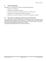
2
Inbetriebnahme Allgemein
Die Vorbereitung zur Inbetriebnahme des Monitors umfasst im Einzelnen folgende Punkte:
• Auspacken
• Überprüfung auf Beschädigung der Komponenten
• Vergleichen der gelieferten Komponenten mit dem Lieferschein
• Verkabelung mit dem Rechnersystem und der Stromversorgung
• Einbau in Ihr System, unter Berücksichtigung technischer und ergonomischer
Gesichtspunkte
2.1
Auspacken und Überprüfen der Einzelteile
Nach dem Auspacken aller gelieferten Komponenten sind diese auf Vollständigkeit und
Transportschäden (Sichtkontrolle) zu überprüfen. Sollten hierbei Mängel festgestellt werden,
benachrichtigen Sie bitte die im Lieferschein ausgewiesene Serviceabteilung. Sie sollten die
Lieferscheinnummer, Seriennummer und Mängelbeschreibung bereithalten.
Für einen späteren Transport des Gerätes ist die Originalverpackung aufzubewahren.
Bedienpanel SCD 1297-K
Seite 9 / 66
DOC-Nr.: b40010de1.doc
Betriebsanleitung
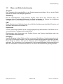
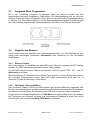
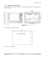
2.2
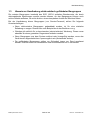
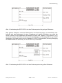
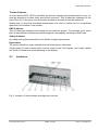
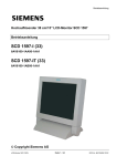
Installation /Einbau des Monitors
Der SCD 1297-K wird als Standard 19” Einschub in einen 19“ Schrank montiert.
Trageschienen sind nicht erforderlich.
Abb. 1: Abmessung des SCD 1297-K
Abb. 2: Schalttafelausschnitt
Bedienpanel SCD 1297-K
Seite 10 / 66
DOC-Nr.: b40010de1.doc
Betriebsanleitung
Wärmeproblematik
Um eine ausreichende Wärmeabgabe zu gewährleisten, sollte um das Gehäuse des SCD
1297-K die Luft frei strömen können. Weiterhin sollte gewährleistet sein, dass an dem
Gehäuse eine Konvektion (Wärmeaustausch) stattfinden kann. Dies gilt insbesondere im
Bereich der Rückwand des Systems.
Bitte bedenken Sie, dass eine überhöhte Temperatur zum Defekt bzw. zur erheblichen
Verkürzung der Lebensdauer des Monitors führen kann.
EMV - Problematik
Das vorliegende Gerät dient als Einbaukomponente in einer industriellen Anwendung. Der
Betreiber der Gesamtanlage ist zur Einhaltung der elektromagnetischen Verträglichkeit nach
dem EMV-Gesetz angehalten.
Sicherheitsproblematik
Alle Spannungs- und Signalanschlüsse sind nach den gültigen Rechtsvorschriften
auszuführen.
Ergonomie
Der Bildschirm sollte von allen Seiten gut und blendfrei einsehbar sein.
Für die Verbindung des VGA-Signals wird ein hochwertiges 75-Ohm-Koaxialkabel
verwendet. Signalkabel von schlechter Qualität können starke Störungen und
Schattenbildung im dargestellten Bild zur Folge haben.
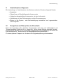
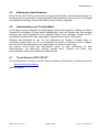
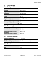
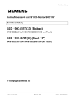
2.3
Schnittstellen
Abb. 3: Lage der Schnittstellen
Bedienpanel SCD 1297-K
Seite 11 / 66
DOC-Nr.: b40010de1.doc
Betriebsanleitung
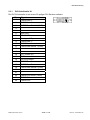
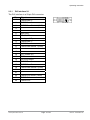
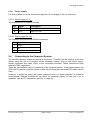
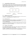
2.3.1
DVI-Schnittstelle X1
Die DVI-Schnittstelle ist mit einem 29-poligen DVI-Stecker realisiert.
Pin
1
Signal
TMDS-Data 2 -
2
TMDS-Data 2 +
3
TMDS-Data Shield 2 (GND)
4
-
5
-
6
DDC-CLK
7
DDC-DATA
8
Analogue V-Sync.
9
TMDS-Data 1 -
10
TMDS-Data 1 +
11
TMDS-Data Shield 1 (GND)
12
-
13
-
14
+5 V Power (In)
15
GND
16
Hot Plug Detect
17
TMDS-Data 0 -
18
TMDS-Data 0 +
19
TMDS-Data Shield 0 (GND)
20
-
21
-
22
TMDS-CLK Shield (GND)
23
TMDS-CLK +
24
TMDS-CLK -
Bedienpanel SCD 1297-K
Seite 12 / 66
DOC-Nr.: b40010de1.doc
Betriebsanleitung
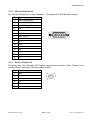
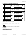
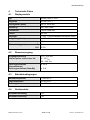
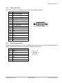
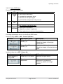
2.3.2
VGA-Schnittstelle X2
Die VGA-Schnittstelle ist mit einer Standard – 15-poligen HD-D-SUB-Buchse realisiert.
Pin
2.3.3
Signal
1
Video Eingang Rot
2
Video Eingang Grün
3
Video Eingang Blau
4
Frei
5
Frei
6
GND (Rot)
5
7
GND (Grün))
15 14
8
GND (Blau)
9
frei
10
GND
11
frei
12
frei
13
H-Sync.
14
V-Sync.
15
frei
4
10
3
9
13
2
8
12
1
7
11
6
Externe Tastatur X3
Rückseitig kann eine Standard PS2-Tastatur angeschlossen werden. Diese Tastatur kann
parallel mit der frontseitigen Tastatur bedient werden.
Pin
Signal
1
Data
2
-
3
GND
4
+5V
5
CLK
6
-
Bedienpanel SCD 1297-K
Seite 13 / 66
DOC-Nr.: b40010de1.doc
Betriebsanleitung
2.3.4
PC-Schnittstelle Tastatur X4
Diese Schnittstelle stellt die Tastaturverbindung mit dem Rechnersystem her und ist als
Standard PS2-buchse ausgeführt. Zur Verbindung mit dem Rechnersystem kann ein
Standard PS2-Kabel (Stecker-Stecker) mit einer Länge von maximal 5 m verwendet werden.
Pin
2.3.5
Signal
1
Data
2
-
3
GND
4
+5V
5
CLK
6
-
PC-Schnittstelle Maus X5
Diese Schnittstelle stellt die Mausverbindung mit dem Rechnersystem her und ist als
Standard PS2-buchse ausgeführt. Zur Verbindung mit dem Rechnersystem kann ein
Standard PS2-Kabel (Stecker-Stecker) mit einer Länge von maximal 5 m verwendet werden.
Pin
Signal
1
Data
2
-
3
GND
4
+5V
5
CLK
6
-
Bedienpanel SCD 1297-K
Seite 14 / 66
DOC-Nr.: b40010de1.doc
Betriebsanleitung
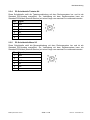
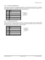
2.3.6
PC-Schnittstelle Tastatur/Maus (Long Distance ) X27
Diese Schnittstelle wird verwendet, wenn zwischen Bedienpanel und Rechnersystem
größere Entfernungen (> 5 m) überbrückt werden müssen. Die Signale für Maus und Tastatur
werden über ein gemeinsames Kabel übertragen. Als Verbindungskabel kann ein Standard
CAT5/6/7 Ethernetkabel mit RJ45 Stecker verwendet werden. Bei Verwendung dieser
Schnittstelle muss auf der PC-Seite ein entsprechender Empfänger verwendet werden, der
diese Signale wieder in die PC-üblichen Signale für Tastatur und Maus umwandelt (siehe auf
Seite 17)
Pin
2.3.7
Signal
1
KBD-DATA+
2
KBD-DATA-
3
MOUSE-DATA-
4
KBD-CLK+
5
KBD-CLK-
6
MOUSE-DATA+
7
MOUSE-CLK-
8
MOUSE-CLK+
Touch Schnittstelle X6
Der Touch kann über die USB- bzw. RS232-Schnittstelle angeschlossen werden.
Pin
Signal
1
DCD
2
RXD
3
TXD
4
DTR
5
GND
6
DSR
7
RTS
8
CTS
9
RI
Bedienpanel SCD 1297-K
Seite 15 / 66
DOC-Nr.: b40010de1.doc
Betriebsanleitung
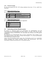
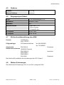
2.3.8
Stromversorgung
Die Stromversorgung des SCD 1297 erfolgt wahlweise über einen 12 VDC- oder24 VDCAnschluss.
2.3.8.1. Spannungsversorgung 12 VDC
Der Anschluss ist eine 3,2 mm DC-Buchse.
Pin
Bezeichnung Beschreibung
O
GND
Spannungseingang GND
z
+12V
Spannungsversorgung +12 VDC
2.3.8.2. Spannungsversorgung 24 VDC
Der Anschluss ist mit einer Phoenix Stecker ausgestattet.
Pin Signal
2.4
1
GND
2
NC
3
+24 VDC
Verbindung mit dem Rechnersystem
Der Monitor ist werkseitig geprüft und voreingestellt. Zur Inbetriebnahme sind alle
Verbindungen wie Versorgungsspannung, Maus, Tastatur und Video (VGA) über die dafür
vorgesehenen Stecker durchzuführen. Die Anschlüsse des Monitors sind EMV-gerecht
auszuführen.
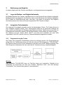
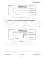
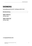
Die Verbindung zum Rechnersystem kann auf zwei verschiedenen Arten erfolgen. Ist die
Leitungslänge zwischen SCD 1297-K und dem Rechnersystem < 5 m, können die Standard
PS2 Verbindungen verwendet werden.
Jedoch sollte berücksichtigt werden, dass diese Schnittstellen nicht für ein industrielles
Umfeld ausgelegt sind. Externe Störfelder können das Rechnersystem über diese
Schnittstellen erheblich beeinflussen bzw. außer Betrieb setzten.
Bedienpanel SCD 1297-K
Seite 16 / 66
DOC-Nr.: b40010de1.doc
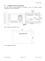
Betriebsanleitung
Abb. 4: Verbindung des SCD 1297-K mit dem Rechnersystem bei geringen Distanzen
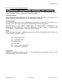
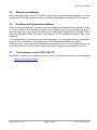
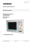
Sind größere Distanzen zwischen Bedienpanel und Rechnersystem zu überbrücken oder
befindet sich das Bedienpanel in einer Umgebung mit starken Störfeldern, so sollte die
zweite Variante mit der speziellen Schnittstelle für Maus und Tastatur (Long Distance, X27)
verwendet werden. Bei dieser Variante werden die Tastatur und Maussignale über ein Kabel
übertragen. Als Kabel kommt hier ein Standard CAT5/6/7 Ethernetkabel (Achtung: Belegung
des Kabels beachten siehe Kap. 2.3.6 auf Seite 15) zum Einsatz.
Abb. 5: Verbindung des SCD 1297-K mit dem Rechnersystem bei großen Distanzen
Bedienpanel SCD 1297-K
Seite 17 / 66
DOC-Nr.: b40010de1.doc
Betriebsanleitung
2.5
Elektrische Inbetriebnahme
Bevor Sie den SCD 1297-K an die Stromversorgung anschließen, sollte überprüft werden, ob
die Stecker der Schnittstellen korrekt angesteckt und verschraubt sind. Wenn ein VGA-Signal
am Bedienpanel anliegt, wird das Bild direkt auf dem Schirm dargestellt.
2.6
Inbetriebnahme der Tastatur/Maus
In der Regel werden während des Startvorgangs eines Rechnersystem Tastatur und Maus
überprüft und initialisiert. Fehlen diese Eingabegeräte, kann der Rechner den Startvorgang
anhalten oder das Eingabegerät ist im späteren Betrieb nicht verfügbar. Gerade bei PCkompatiblen Rechnern wird eine nachträglich angeschlossene Maus nicht erkannt.
Während des Betriebes ist das An- und Abstecken der Tastatur und/oder Maus zu
vermeiden. Hierbei kann es u.a. zu Inkonsistent der Daten im Rechner und der Tastatur
kommen. Eine Fehlinterpretation der Tastaturdaten im Rechner ist die Folge.
Aus diesem Grund sollte das Bedienpanel immer vor oder gleichzeitig mit dem
Rechnersystem mit Spannung versorgt werden damit Tastatur und Maus vom
Rechnersystem erkannt und initialisiert werden können.
2.7
Touch-Version SCD 1297-KT
Für den Betrieb des Touchs ist ein SW-Treiber erforderlich. Dieser kann von der Internetseite
www.siemens.com/displays
geladen werden.
Bedienpanel SCD 1297-K
Seite 18 / 66
DOC-Nr.: b40010de1.doc
Betriebsanleitung
3
Bedienung und Abgleich
In diesem Kapitel wird die Funktion aller Bedien- und Abgleichelemente dargestellt.
3.1
Lage der Bedien- und Abgleichelemente
Die Bedienelemente wie Tastatur und Maus sind von der Frontseite des Gerätes zugänglich.
Bedienelemente zum Abgleich des Monitors sind von der Rückseite des Gerätes zugänglich.
Die 4-Tasten zur OSD-Steuerung sind in der Abb. 1 auf Seite 10 ersichtlich. Der Abgleich
des Monitors kann auch über eine extern angesteckte PS2-Tastatur erfolgen.
3.2
Integrierte Folientastatur
Die integrierte Folientastatur besteht aus 94 frei definierbaren Tasten. Die Tasten können in
zwei Gruppen eingeteilt werden. Eine Tastengruppe bildet die so genannten Softkeys die
links, rechts und unterhalb des Displays angeordnet sind. Diese Tasten können mit Hilfe von
Einsteckstreifen beschriftet werden. Die fest beschrifteten Tasten bilden die zweite Gruppe.
Die Softkeys und die Tasten HELP, SHIFT und ACK sind zusätzlich mit einer LED
ausgestattet. Die LED‘s können über die Tastaturschnittstelle angesteuert werden.
3.2.1
Programmierung der Tasten
Alle Tasten der integrierten Folientastatur können frei definiert werden. Die Programmierung
erfolgt über die Tastaturverbindung mit Hilfe des kleinen DOS-Programms “TCLOAD.EXE”.
Die Tastenzuordnung wird in einer editierbaren Liste oder einer Excel-Tabelle festgelegt. Das
DOS-Programm interpretiert die Liste und Lädt die Tastenzuordnung in das Bedienpanel.
Wichtig:
Das Programm TCLOAD.EXE kann nur Text-files lesen und verarbeiten. Deshalb ist es
notwendig, die Excel-Liste mit Hilfe der Funktion “Speichern unter” und dem Dateityp
„Formatierter Text (Leerzeichen getrennt)“ abzuspeichern.
Bedienpanel SCD 1297-K
Seite 19 / 66
DOC-Nr.: b40010de1.doc
Betriebsanleitung
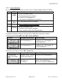
3.2.1.1. Aufbau der Tastenzuordnungstabelle
In der Tabelle werden verschiedene Schlüsselwörter, Zeichen und ein definierter Syntax
verwendet. Die mitgelieferte Zuordnungstabelle beinhaltet alle Definitionen der Tasten die
fest beschriftet sind.
; Tastentabelle Bedienpanel XXY an der Anlage ZYX
;
#Name Simatictabelle
23
;
;Grundebene, Ebene 0
;
X (0...11) Y (0...7) MF-II Key No.
0
0
19
Flags
Kommentar
T
; E
1
0
38
T
; K
2
0
17
T
; Q
3
0
18
T
; W
4
5
0
0
11
6
T
T
; 0
; 5
6
0
83
T
; Cursor Up
7
0
76
T
; Delete
Abb. 6: Tastenzuordnungstabelle
Die Tabelle besteht aus einem Tabellenkopf in dem der Benutzer diverse Informationen als
Kommentar hinterlegen kann, die Tastenzuordnungstabelle der ersten Tastenebene und der
Tastenzuordnungstabelle der zweiten Ebene. Zwischen den Tabellen der beiden Ebenen
wird noch definiert, welche der Tasten als Umschalttaste zwischen den Ebenen dient.
3.2.1.2. Schlüsselwörter bzw. Zeichen
#Name
Hier kann der Tabelle ein Name gegeben werden. Dieser Name wird im
Bedienpanel abgespeichert und dient zur späteren Identifikation der geladenen
Tabelle.
#Level1
Nach diesem Schlüsselwort wird die Taste (Tastenkoordinate) festgelegt, die zur
Umschaltung zwischen den beiden Ebenen dienen soll.
Beispiel: #Level1 8 6
D.h. die Taste X=8, Y=6 wird als Umschalttaste definiert.
;
Das Semikolon definiert den Beginn eines beliebigen Kommentars.
Bedienpanel SCD 1297-K
Seite 20 / 66
DOC-Nr.: b40010de1.doc
Betriebsanleitung
3.2.1.3. Syntax eines Tabelleneintrages
X Tastenkoordinate
Y Tastenkoordinate
Tastennummer Flag
Kommentar
Als Trennung zwischen den einzelnen Informationen wie X-Tastenkoordinate und YTastenkoordinate müssen Leerzeichen verwendet werden.
Tastenkoordinate
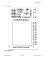
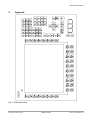
Diese Matrixkoordinate bestimmt die zu definierende Taste. Die Abb. 7 auf Seite 32 im
Anhang zeigt alle Tasten des SCD 1297-K und deren Koordinaten.
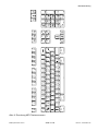
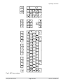
Tastennummer
Die Tastennummer ist die einer äquivalenten MF2-Taste. In der Abb. 8 auf Seite 33 im
Anhang werden die Tastennummer einer Standard MF2-Tastatur dargestellt.
Zwischen Rechner und Tastatur werden immer nur Tastennummern ausgetauscht. Die
Belegung der Taste selbst d.h., ob auf dem Bildschirm nun ein „Z“ oder „Y“ erscheint, wird
durch Tabellen (Tastaturtreiber) im Rechner selbst festgelegt.
Flags
Die Flags legen bestimmte Verhaltensweisen bzw. welche Controltaste beim Drücken der
Taste mit aktiviert werden soll fest:
R,r
L,l
G,g
A,a
C,c
T,t
Rechte Shift-Taste
Linke Shift-Taste
AltGr-Taste
Alt-Taste
Control Taste / Strg-Taste
Autorepeat, Typematic
Kommentar
Beliebiger Kommentar beginnend mit “;”. Der Eintrag des Kommentars endet mit der
Zeilenendmarkierung (CR bzw. CR/LF)
Bedienpanel SCD 1297-K
Seite 21 / 66
DOC-Nr.: b40010de1.doc
Betriebsanleitung
3.2.2
Programmierung der LEDs
Die Folientastatur verfügt über 39 LED’s die in Kombination mit einigen Tasten angeordnet
sind. Diese LED’s können z.B. als Quittungs- oder Freigabesignale dienen.
Die Ansteuerung der LED’s erfolgt, wie auch die Programmierung der Tasten, über die
Tastaturverbindung zwischen Rechner und Bedienpanel. Da die MF2-Tastaturspezifikation,
außer der NumLock-, CapsLock- und ScrollLock-LED, nicht vorsieht zusätzliche LED’s
anzusteuern, wurde ein Sonderkommando implementiert. Mit diesem Kommando können die
einzelnen LED’s ein und ausgeschaltet werden.
Die Zuordnung der LED-Nummern zu der LED-Position ist in der Abb. 7 auf Seite 32.
Das Sonderkommando für die LED-Daten lautet OxEA gefolgt von 10 Bytes mit den LEDInformationen.
Aufbau des Protokolls
0xEA
B1H
0xEA
: Sonderkommando
B1-B5
: LED Information als ASCII-Hexformat
B1L
B2H
B2L
B3H
B3L
B4H
B4L
B5H
B5L
Wichtig ist, dass die LED-Bytes B1-B5 im ASCII-Hexformat übermittelt werden, d.h. für jedes
LED-Byte, „Bx“ müssen physikalisch zwei Bytes übertragen werden.
Für jedes Byte das an das Bedienpanel gesendet wird, sendet das Bedienpanel ein
Quittierungsbyte (OxFA) an den Rechner zurück.
Bedienpanel SCD 1297-K
Seite 22 / 66
DOC-Nr.: b40010de1.doc
Betriebsanleitung
Die Zuordnung der LED-Bytes B1-B5 zu dem jeweiligen LED:
Byte
LED
Taste
Beispiel
Byte LED
B1.0
LED40*
B1.1
Taste
B3.4 LED20 F4
LED39
Shift
0 ,B1L’
X 1 A = 0x41
B1.2
LED38
ACK
0
B3.6 LED18 F2
0
B1.3
LED37
Help
X 1
B3.7 LED17 F1
X 1
B1.4
LED36
F20
B4.0 LED16 S16
B1.5
LED35
F19
X 1 ,B1H’
0 1 = 0x31
B1.6
LED34
F18
B1.7
LED33
F17
B2.0
LED32
F16
B2.1
LED31
F15
B2.2
LED30
F14
B2.3
LED29
B2.4
B3.5 LED19 F3
Beispiel
X 1 ,B3H’
X 1 B = 0x42
B4.1 LED15 S15
0 ,B4L’
0 0 = 0x30
0
B4.2 LED14 S14
0
0
B4.3 LED13 S13
0
X 1 ,B2L’
0 D = 0x44
B4.4 LED12 S12
B4.5 LED11 S11
X 1 ,B4H’
0 D = 0x44
1
B4.6 LED10 S10
X 1
F13
1
B4.7 LED9
S9
X 1
LED28
F12
B5.0 LED8
S8
B2.5
LED27
F11
0 ,B2H’
0 4 = 0x34
B5.1 LED7
S7
0 ,B5L’
0 8 = 0x38
B2.6
LED26
F10
X 1
B5.2 LED6
S6
0
B2.7
LED25
F9
0
B5.3 LED5
S5
X 1
B3.0
LED24
F8
B5.4 LED4
S4
B3.1
LED23
F7
0 ,B3L’
X 1 E = 0x45
B5.5 LED3
S3
X 1 ,B5H’
X 1 F = 0x46
B3.2
LED22
F6
X 1
B5.6 LED2
S2
X 1
B3.3
LED21
F5
X 1
B5.7 LED1
S1
X 1
*: Die LED 40 ist auf der Folientastatur nicht vorhanden.
ASCII - Kodierung: 0 ... 9 => 0x30 ... 0x39; A ... F => 0x41 … 0x46
Beispiele:
Alle LED „ON“
0xEA, 0x46, 0x46, 0x46, 0x46, 0x46, 0x46, 0x46, 0x46, 0x46, 0x46
Alle LED “OFF”
0xEA, 0x30, 0x30, 0x30, 0x30, 0x30, 0x30, 0x30, 0x30, 0x30, 0x30
Beispiel laut Tabelle (X= LED “ON“):
0xEA, 0x31, 0x41, 0x34, 0x44, 0x42, 0x45, 0x44, 0x30, 0x46, 0x38
Bedienpanel SCD 1297-K
Seite 23 / 66
DOC-Nr.: b40010de1.doc
Betriebsanleitung
3.3
Integrierte Maus (Fingermaus)
Die in der Frontplatte integrierte “Fingermaus” erfüllt die gleiche Funktion wie eine
herkömmliche Microsoft kompatible 2-Tasten-Maus. Die Mausbewegung wird mit Hilfe des
Mittleren Feldes der Maus durchgeführt. Das Feld ist in die gewünschte Bewegungsrichtung
zu drücken. Die Druckstärke wirkt sich auf die Bewegungsgeschwindigkeit des Mauszeigers
aus. Die beidseitig angeordneten Tasten entsprechen der Linken und Rechten Maustaste.
3.4
Abgleich des Monitors
Da es keine Normung bezüglich des Videoausgangssignals von VGA-Grafikkarten gibt,
erfolgt beim erstmaligen Einschalten automatisch eine Anpassung an die verwendete
Graphikkarte.
3.4.1
Externe Tastatur
Wie schon erwähnt, ist die Bedienung des OSD‘s auch über eine angesteckte MF2-Tastatur
möglich. Die OSD-Steuerung wird mit den Cursor Tasten bedient.
Um das OSD über die externe Tastatur zu aktivieren, sind die Tasten CTRL-, ALT-, und „M“
gleichzeitig zu drücken.
Wird innerhalb von 10 Sekunden keine weitere Taste gedrückt, schaltet der Monitor wieder in
den normalen Tastaturmodus zurück. Das OSD selbst verschwindet auch nach ca. 10
Sekunden (je nach Einstellung im Utility-Menü).
3.4.2
OSD-Menü / Quick-OSD-Menü
Das „On Screen Display“ OSD ist ein Menüsystem, dass auf den Bildschirm dargestellt wird.
Mit Hilfe des Menüsystems und den beschriebenen Bedienelemente sind alle Einstellungen
des Monitors durchzuführen. Zur Steuerung des OSD sind nur die vier Tasten notwendig.
Es gibt außer den Einstellmöglichkeiten im OSD-Menü eine weitere Möglichkeit, die wichtigsten Funktionen wie Helligkeit, Kontrast und automatischer Bildabgleich direkt über einen
Schnellzugriff, das so genannte Quick-OSD-Menü zu verändern.
Bedienpanel SCD 1297-K
Seite 24 / 66
DOC-Nr.: b40010de1.doc
Betriebsanleitung
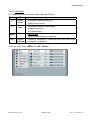
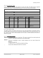
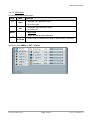
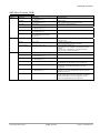
3.4.2.1. Quick-OSD-Menü
Die Tasten des Bedienelements und der externen Tastatur haben folgende Funktion.
Taste
Funktion(en)
(+)
MF2
Cursor
rechts
(-)
Cursor
links
• Einstellparameterwert erniedrigen
MEN
Enter
SET
•
•
•
•
Quick-OSD-Menü-Aufruf
Einstellparameterwert erhöhen
Auswahl der Eingangsquelle
Automatischen Bildabgleich durchführen
• Keine Funktion im Quick-OSD-Menü
Cursor • Quick-OSD-Menü-Aufruf
Up/Down
• Einstellen von Kontrast, Helligkeit
• Zoom und Bild-in-Bild (PIP) Eigenschaften
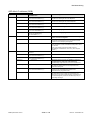
Folgende Einstellungen können über das Quick-OSD-Menü aufgerufen werden:
Aufruf durch die Taste <SET> bzw. MF - Cursor Up/Down
Funktion
Einstellen/Einstellwert
Beschreibung
Einstellbereich: 0 bis 100
über Einstelltasten (+/-)
Kontrast einstellen
Anpassen der Wiedergabe der
hellen Bildpartien
Einstellbereich: 0 bis 100
über Einstelltasten (+/-)
Helligkeit einstellen
Anpassen der Wiedergabe der
dunklen Bildpartien.
Aufruf durch die Taste <+> bzw. MF - Cursor Up
Funktion
Einstellen/Einstellwert
Quellenauswahl
digital DVI, analog
RGB
Auswahl durch erneutes Selektion der Eingangsquelle
Drücken der Taste <+>
Abgleich durch Drücken
der Taste <+>
durchführen
Bedienpanel SCD 1297-K
Seite 25 / 66
Beschreibung
Führt einen automatischen Bildabgleich durch. Abgleich von
Frequenz, Phase und Bildposition.
DOC-Nr.: b40010de1.doc
Betriebsanleitung
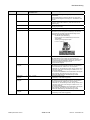
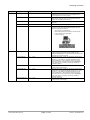
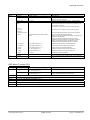
3.4.2.2. OSD-Menü
Die Tasten des Bedienelements haben folgende Funktion.
Taste
(+)
(-)
MENU
MF2
Funktion(en)
Cursor • Einstellparameterwert erhöhen
rechts
• Auswahl nach rechts
Cursor • Einstellparameterwert erniedrigen
links
• Auswahl nach links
• Ein-/Ausschalten
Enter • OSD-Aufruf
•
SET
Cursor •
Up/Down
Hauptmenü/Untermenü auswählen
Punkte im Hauptmenü / Untermenü von oben nach unten
durchgehen, auswählen
Aufruf durch die Taste <MEN> bzw. MF - <Enter>
Bedienpanel SCD 1297-K
Seite 26 / 66
DOC-Nr.: b40010de1.doc
Betriebsanleitung
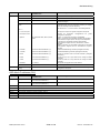
OSD-Menü-Funktionen (RGB)
Hauptmenü
Funktion
Einstellen/Einstellwert/
Einstellbereich
Beschreibung
Bild 1
Helligkeit
Einstellbereich:
0 bis 100 über Einstelltasten (+/-)
Helligkeit einstellen
Anpassen der Wiedergabe der hellen Bildpartien
Kontrast
Einstellbereich:
0 bis 100 über Einstelltasten (+/-)
Kontrast einstellen
Anpassen der Wiedergabe der dunklen Bildpartien
H Position
Einstellbereich:
0 bis 100 über Einstelltasten (+/-)
Bild in horizontaler Richtung verschieben
V-Position
Einstellbereich:
0 bis 100 über Einstelltasten (+/-)
Bild in vertikaler Richtung verschieben
Phase
Einstellbereich:
0 bis 31 über Einstelltasten (+/-)
Phase des Eingangssignals einstellen
Frequenz
Einstellbereich:
950 bis 1050 (bildabhängig)
über Einstelltasten (+/-)
Frequenz des Eingangssignals einstellen
Schärfe
1, 2, 3, 4, 5
Schärfe des Bildes durch Wahl eines der fünf Schärfegrade
(Filter). 1=scharf und 5=glätten
Gamma
Linear oder CRT
Gamma-Kurve korrigieren
Anliegende Farbwerte werden mit einem bestimmten Faktor
versehen und an das Display weitergeleitet
Farbtemperatur
5000 - 7200 – 9300 - VAR
Gewünschte Farbtemperatur bzw. Farbton einstellen
Drei festdefinierte und eine einstellbare Farbtemperatur stehen
zur Auswahl.
Wird „VAR“ aktiviert erscheinen für RGB, jeweils ein
Einstellbalken. Einstellbereich: 0 bis 100 % (50% entspricht
Faktor 1)
OSD
Auswahl zwischen neun festdefinierten OSD
Positionen
Position OSD definieren
OSD H-Position
Einstellbereich:
0 bis 100 über Einstelltasten (+/-)
OSD-Menü in horizontaler Richtung verschieben
OSD V-Position
Einstellbereich:
0 bis 100 über Einstelltasten (+/-)
OSD-Menü in vertikaler Richtung verschieben
OSD Dauer
5 ... 60 Sekunden
Einstellen der Zeit, nach der das OSD-Menü automatisch
ausgeblendet wird, falls keine Taste betätigt wird.
Die Einstellung erfolgt zwischen 5 und 60 s in Schritten zu 5 s
OSD Hintergrund
Opaque – Transparent
Hintergrundfarbe des OSD-Menüs auswählen
Sie haben die Wahl zwischen einem transparenten oder
deckenden Hintergrund.
Backlight
Einstellbereich:
0 bis 100 über Einstelltasten (+/-)
Helligkeit der Display-Hinterleuchtung einstellen
Damit kann die Gesamthelligkeit des Bildes an die
Raumbeleuchtung angepasst werden.
Störunterdrückung
EIN – AUS
Standardeinstellung AUS.
Bei EIN: Aktivierung der Funktion zur Unterdrückung von
Störungen in den Synchronisationssignalen. Verhindert einen
erneuten Bildabgleich (erscheinen des Bildhintergrunds) bei
kurzzeitigen Störungen
Bild ...
Optionen 1
Bedienpanel SCD 1297-K
Seite 27 / 66
DOC-Nr.: b40010de1.doc
Betriebsanleitung
Hauptmenü
Funktion
Einstellen/Einstellwert/
Einstellbereich
Beschreibung
Optionen 2
DPMS
EIN – AUS
Display Power Management System (DPMS) ein- oder
ausschalten.
Ist das DPMS aktiviert, schaltet der Monitor ab, sobald keine
Synchronisationssignale mehr anliegen d.h. der Bildschirm wird
dunkel.
Signal suchen
AUS – EIN – Standard
Standardeinstellung: EIN
Hinweis: Videoquellen selektieren, (nicht relevant da nur ein
RGB-Eingang
Löschfarbe
Rot – Grün – Blau – Schwarz
Auswahl der Hintergrundfarbe des Bildschirms wenn kein
Eingangssignal anliegt
Display
–
Panelauflösung wird angezeigt (nicht die der Videoquelle)
Info Signalquelle
Ein – Aus
Signalquellenanzeige ein- oder ausschalten
Bei Änderung einer der folgenden Einstellungen erscheint auf
dem Bildschirm kurzzeitig die Signalquellenanzeige mit den
aktuellen Signalquelleninformationen:
Signalquelle (z.B. RGB Analog)
Modus (Nummer des Tabelleneintrages der internen
Timingtabelle)
Auflösung der Eingangsvideoquelle
H- und V- Frequenz
Störunterdrückung
EIN – AUS
Standardeinstellung AUS.
Bei EIN: Aktivierung der Funktion zur Unterdrückung von
Störungen in den Synchronisationssignalen. Es verhindert einen
erneuten Bildabgleich während der Darstellung eines Videosignals bei kurzzeitigen Störungen auf den
Synchronisationssignalen.
Standardeinstellung AUS.
Bei EIN: Das gerade dargestellte Videotiming wird gespeichert
und mit einer höheren Toleranz in H- und V-Frequenz
verarbeitet. D.h. die Einstellungen dieses Timings werden immer
verwendet, selbst wenn durch Störungen Variationen in H- und
V-Frequenz auftreten.
Es verhindert beim Erkennen eines störbehafteten Videosignals
eine fehlerhafte Timingerkennung die sich z.B. in einer
fehlerhaften Bildzentrierung oder Bildauflösung darstellt.
Optionen 3
RGB-Signal
verriegeln
1
EIN
RGB-Signal
entriegeln
1
AUS <+ Taste>
Standardeinstellung AUS.
(Videotiming 1 wird wieder freigegeben)
RGB-Signal
verriegeln
2
EIN
Standardeinstellung AUS.
Bei EIN: Das gerade dargestellte Videotiming wird gespeichert
und mit einer höheren Toleranz in H- und V-Frequenz
verarbeitet. D.h. die Einstellungen dieses Timings werden immer
verwendet, selbst wenn durch Störungen Variationen in H- und
V-Frequenz auftreten.
Es verhindert beim Erkennen eines störbehafteten Videosignals
eine fehlerhafte Timingerkennung die sich z.B. in einer
fehlerhaften Bildzentrierung oder Bildauflösung darstellt.
RGB-Signal
entriegeln
2
AUS <+ Taste>
Bedienpanel SCD 1297-K
<+ Taste>
<+ Taste>
Standardeinstellung AUS.
(Videotiming 2 wird wieder freigegeben)
Seite 28 / 66
DOC-Nr.: b40010de1.doc
Betriebsanleitung
Hauptmenü
Funktion
Einstellen/Einstellwert/
Einstellbereich
Utilities
Sprache
Englisch – Deutsch
Sprache für die Bedienung des OSD-Menüs auswählen
Kalibration
<+> drücken
Abgleich des internen A/D-Wandlers (Menü-Führung folgen)
Werkseinstellung
<+> drücken
Rücksetzen aller Funktionen wie Helligkeit, Kontrast, ... auf die
Werkseinstellungen.
Installation
Mode
<+> drücken
Anpassung an Videosignale die nicht als Timingdaten im Gerät
gespeichert sind (wenn die angezeigte Auflösung am Display
nicht der Auflösung der Quelle entspricht).
RGB-
Beschreibung
Bei Drücken der <+>-Taste erscheinen 9 Einstellmöglichkeiten
Bei <+>,
Infos
H- und V-Frequenz
–
Anzeige H/V Frequenz der gerade anliegenden Videoquelle
H/V-total, H/V-start
–
Anzeige der verwendeten
anliegenden Videoquelle
Optionen
Var. RGB-Mode inaktiv, Mode1, Mode2,
Mode3
Inaktiv: nur verwenden der internen Timingtabellen
Mode1: verwenden der eingestellten Parameter mit kompletten
automatischem Abgleich (wird in der Regel verwendet)Mode2:
verwenden der eingestellten Parameter mit kompletten
automatischem Abgleich ohne den automatische „Positions“
Abgleich
Mode3: verwenden der eingestellten Parameter mit kompletten
automatischem Abgleich ohne den automatischen „Frequenz“
Abgleich
H-sichtbar
100 bis 2000 über Einstelltasten (+/-)
Horizontale Bildauflösung einstellen (wichtigster Parameter)
V-sichtbar
100 bis 2000 über Einstelltasten (+/-)
Vertikale Bildauflösung einstellen (wichtigster Parameter)
H-total
100 bis 2500 über Einstelltasten (+/-)
Anzahl der gesamten Pixel in einer Zeile einstellen (wichtigster
Parameter)
H-Start
0 bis 750 über Einstelltasten (+/-)
Anzahl der Pixel von H-Sync-Start bis zum Anfang des Bildes
einstellen
V-Start
0 bis 500 über Einstelltasten (+/-)
Anzahl der Zeilen von V-Sync-Start bis zum Anfang des Bildes
einstellen
Installieren
<+> drücken
Eingestellte Timingparameter werden aktiviert
Timingparameter
der
gerade
Testmuster
<+> drücken
Darstellung eines Testbildes
Firmware, Auflösung,
Timing
–
Anzeige von Firmwarestand und den Daten der gerade
anliegenden Videoquelle
OSD-Menü-Funktionen (DVI)
Hauptmenü
Funktion
Einstellen
Einstellbereich
/Einstellwert/
Bild
Helligkeit
Einstellbereich:
0 bis 100 über Einstelltasten(+/-)
Helligkeit einstellen
Kontrast
Einstellbereich:
0 bis 100 über Einstelltasten(+/-)
Kontrast einstellen
Bild...
Siehe Kapitel „OSD-Menü-Funktionen (RGB)“, Seite 27
Option 1
Siehe Kapitel „OSD-Menü-Funktionen (RGB)“, Seite 27
Option 2
Siehe Kapitel „OSD-Menü-Funktionen (RGB)“, Seite 28
Option 3
Siehe Kapitel „OSD-Menü-Funktionen (RGB)“, Seite 28
Utilities
Siehe Kapitel „OSD-Menü-Funktionen (RGB)“, Seite 29
Info
Siehe Kapitel „OSD-Menü-Funktionen (RGB)“, Seite 29
Bedienpanel SCD 1297-K
Seite 29 / 66
Beschreibung
DOC-Nr.: b40010de1.doc
Betriebsanleitung
4
Technische Daten
4.1
Displaymodule
Typ
Aktives FarbTFT-LCD
Diagonale
30,8 cm (12,1")
Displayfläche (WxH)
246,0 x 184,5 mm
Auflösung
800 x 600 Pixels
Pixelblende
0,308 x 0,308 mm²
Farben
262.144
Backlight
2 x CCFT (Cold Cathode Fluorescent Tube)
Helligkeit (typisch)
ca. 370 cd/m²
Kontrast
450:1
Blickwinkel (typisch)
4.2
L/R 70°
O/U 50°/60°
Stromversorgung
Eingangsspannung
Limited power source max. 8A
11,4 – 12,6 VDC
18 – 36 VDC
100 – 240 VAC
Leistungsaufnahme
(Normalbetrieb)
ca. 25 W
Leistungsaufnahme (StandBy)
ca. 5 W
4.3
Betriebsbedingungen
Betriebstemperatur
0 bis +45°C
Lagertemperatur
-25 bis +60°C
Feuchtigkeit
Max. 95% (keine Kondensation)
4.4
Geräteschutz
Schutzart frontseitig
IP65
Schutzart rückseitig
IP20
Bedienpanel SCD 1297-K
Seite 30 / 66
DOC-Nr.: b40010de1.doc
Betriebsanleitung
4.5
Gehäuse
Gewicht
ca. 4,5 kg
Material Gehäuse
Aluminium
4.6
Eingangssignal (Video)
Pegel
0,7VSS RGB analog bei 75 Ω
Bandbreite
140 MHz (-3 dB)
Impedanz
75 Ω
Synchronisation
- Sep. Sync. (TTL)
- Sync on green
- Composite Sync
H Frequenz
30 bis 97 kHz
V Frequenz
50 bis 100 Hz
4.7
EU-Konformitätserklärung über EMV
Produkt
LCD-Monitor
SCD 1297-KT
Prüfgrundlagen
EG-Rahmenrichtlinien
No. 89/336/EWG
No. 73/23/EWG
EN 50081-2
Angewandte
Harmonisierte Normen (EN55022 Class A)
Emissions
EN61000-6-2
EN610003-2
EN610003-3
Immission
EN 60950
Sicherheit
Das Gerät erfüllt zusätzlich die Anforderungen der FCC Class A.
4.8
Weitere Zulassungen:
Das Gerät hat die Zulassungen CE, UL und CUL (entspricht CSA).
Bedienpanel SCD 1297-K
Seite 31 / 66
DOC-Nr.: b40010de1.doc
Betriebsanleitung
Anhang
SIEM ENS
5
Abb. 7: Tastaturmatrix
Bedienpanel SCD 1297-K
Seite 32 / 66
DOC-Nr.: b40010de1.doc
Bedienpanel SCD 1297-K
!
1
Seite 33 / 66
58
Strg
44
30
16
1
2
45
>
< |
46
Alt
S
W
18
Y
3
²
A
31
"
2
§
3
60
32
F2
113
17
Q
@
112
110
^
F1
ESC
X
4
D
19
E
47
³
114
F3
33
$
4
C
5
48
R
V
6
%
5
34
F
20
115
F4
49
G
21
T
35
&
6
B
7
116
F5
50
Z
H
22
F6
36
51
23
U
61
N
8
/
7 {
117
J
F7
37
M
9
I
52
(
8 [
118
µ
K
24
F8
38
;
,
10
L
25
O
53
)
9 ]
119
39
:
.
11
P
54
=
0 }
Ö
26
55
27
62
`
´
41
Ä
121
F10
Ü
Alt Gr
-
12
?
ß \
40
F9
120
13
57
42
'
#
28
*
+ ~
122
F11
64
Strg
15
43
123
F12
79
81
76
84
83
Ende
80
75
Entf
Pos1
125
Rollen
Einfg
124
Druck
89
86
Bild
85
Bild
126
Pause
92
91
0
Einfg
93
1
Ende
4
7
Pos1
90
Num
99
2
5
8
98
97
96
95
÷
102
101
104
,
Entf
103
3
Bild
6
9
Bild
100
×
108
Enter
106
105
+
-
Betriebsanleitung
Abb. 8: Zuordnung MF2-Tastennummern
DOC-Nr.: b40010de1.doc
Operating instruction
High Resolution 31 cm/12“ LCD-Control Panel SCD 1297-KT (33)
Operating Instruction
SCD 1297-K (33) (Rack 19")
6GF6240-7MB
© Copyright Siemens AG
Control panel SCD 1297-K
Page 34 / 66
DOC-Nr.: b40010de1.doc
Operating instruction
No part of this document may be
reproduced or transmitted without
express permission. Violations will
result in prosecution. All Rights
reserved.
© 2006 All Rights reserved.
Control panel SCD 1297-K
Page 35 / 66
DOC-Nr.: b40010de1.doc
Operating instruction
Contents
1
1.1
1.2
1.3
Overview ..............................................................................................................38
Layout of this handbook ........................................................................................39
Warnings and safety notes....................................................................................40
Instructions for handling assemblies susceptible to electrostatic shock ................41
2
General installation.............................................................................................42
2.1
Removing the packaging and checking individual parts........................................42
2.2
Installation of the monitor ......................................................................................43
2.3
Interfaces ..............................................................................................................44
2.3.1 DVI interface X1 ....................................................................................................45
2.3.2 VGA interface X2 ..................................................................................................46
2.3.3 External keyboard X3............................................................................................46
2.3.4 PC interface keyboard X4 .....................................................................................47
2.3.5 PC interface mouse X5 .........................................................................................47
2.3.6 PC interface keyboard/mouse (Long Distance) X27 .............................................48
2.3.7 Touch interface X6 ................................................................................................48
2.3.8 Power supply.........................................................................................................49
2.3.8.1. Power supply 12 VDC .............................................................................................49
2.3.8.2. Power supply 24 VDC .............................................................................................49
2.4
Connecting to the Computer System ....................................................................49
2.5
Electrical Installation .............................................................................................51
2.6
Installing the Keyboard and Mouse .......................................................................51
2.7
Touch-screen version SCD 1297-KT ....................................................................51
3
Operation and Alignment ...................................................................................52
3.1
Location of the Operation and Alignment Control..................................................52
3.2
Integrated Foil keyboard .......................................................................................52
3.2.1 Programming the Keys..........................................................................................52
3.2.1.1. Key Definition Table ..............................................................................................53
3.2.1.2. Keywords/characters.............................................................................................53
3.2.1.3. Syntax of a table entry ..........................................................................................54
3.2.2 Programming the LEDs.........................................................................................55
3.3
Integrated Mouse (Finger-mouse).........................................................................57
3.4
Alignment of the monitor .......................................................................................57
3.4.1 External keyboard .................................................................................................57
3.4.2 OSD-Menu / Quick-OSD-Menu .............................................................................57
3.4.2.1. Quick-OSD-Menu..................................................................................................58
3.4.2.2. OSD-Menu ............................................................................................................59
4
4.1
4.2
4.3
4.4
4.5
4.6
4.7
4.8
Technical Data.....................................................................................................63
Display module......................................................................................................63
Power supply.........................................................................................................63
Operating Condition ..............................................................................................63
Protection ..............................................................................................................63
Enclosure ..............................................................................................................64
Input signal (Video) ...............................................................................................64
EU Declaration of Conformity on EMC..................................................................64
Additional certifications .........................................................................................64
5
Appendix..............................................................................................................65
Control panel SCD 1297-K
Page 36 / 66
DOC-Nr.: b40010de1.doc
Operating instruction
Figures
Fig. 1: Dimensions of the SCD 1297-K ..............................................................................43
Fig. 2: Cut out control panel...............................................................................................43
Fig. 3: Location of the interfaces and alignment controls ...................................................44
Fig. 4: Connecting the SCD 1297-K to the computer system over a short distance ..........50
Fig. 5: Connecting the SCD 1297-K to the computer system over a longer distance ........50
Fig. 6: Key definition table..................................................................................................53
Fig. 7: Keyboard matrix......................................................................................................65
Fig. 8: MF2 key numbers ...................................................................................................66
Control panel SCD 1297-K
Page 37 / 66
DOC-Nr.: b40010de1.doc
Operating instruction
1
Overview
The SCD 1297-K is a control panel for PC-compatible computer systems and can be used as
a man machine interface (MMI) platform for a wide variety of visualization systems. Special
interfaces make it possible to have the SCD 1297-K in a different location as the computer
system. Ninety-four keys and a “finger mouse” are provided for software control and
operation. The 94 keys can be individually configured.
The SCD 1297-K was developed and constructed especially for industrial applications. Its
compact 19” rack format enables it to be used in applications where a complete computer
system would be unsuitable, due to space or environmental restrictions or where the
computer and operating interface must be in different rooms.
As is the case for all industrial systems, the SCD 1297-K has been designed to withstand the
particular demands placed on such equipment, e.g., it is resistant to electromagnetic
radiation and can withstand a large temperature range. The TFT-LCD display in this control
panel minimizes picture geometry distortion and color patches. The screen remains flickerfree even at the low refresh rate of 50 Hz. Images of higher or lower resolution than that of
the screen will be contracted or expanded to fit on the display.
The SCD 1297-K can display up to 256k (16.7 million using interpolation) colors
simultaneously allowing true color images and videos to be displayed without limitations. The
SCD 1297-K contains special hardware to convert the incoming analog VGA or digital DVI
signal into a form recognizable to the display controller thus guaranteeing compatibility with
standard CRT monitors.
A clear and easy-to-use OSD (On Screen Display) is used to adjust the alignment of the
display. The “Automatic Alignment” feature removes the necessity for tedious adjustments of
picture position and phase, etc. At the press of a button, the monitor performs the alignment
automatically.
The SCD 1297-K is equipped with an active 12.1” color TFT display module with a resolution
of 800 x 600 pixels. The VESA DPMS power management system allows significant
reduction in power consumption when the synchronization signal from the computer has
been switched off, compared with that under “normal” operation.
Control panel SCD 1297-K
Page 38 / 66
DOC-Nr.: b40010de1.doc
Operating instruction
1.1
Layout of this handbook
This handbook should be kept within reach while installing and operating the LCD-monitor. It
has been laid out so that even inexperienced users can find the information they require.
Chapters are clearly arranged according to subject.
In detail, the chapters are arranged as follows:
Chapter 1
Introduction
This chapter provides a brief description of the SCD 1297-K, including its
properties, application areas and special features.
Chapter 2
Installation
This chapter is mainly concerned with preparing the LCD-monitor for use, its
installation and cabling.
Chapter 3
Operation
All operations and adjustment possibilities for the SCD 1297-K are described
here.
Chapter 4
Technical Data
This chapter contains technical details such as dimensions, power supply,
environmental considerations and EMC data.
Important:
The manufacturer has gone to great lengths to match the quality of the
documentation to the high standard of this product. In achieving this, we are
reliant on the support of our customers.
Control panel SCD 1297-K
Page 39 / 66
DOC-Nr.: b40010de1.doc
Operating instruction
1.2
Warnings and safety notes
Transport
The LCD-monitor should only be transported in its original packaging to ensure it will be
protected against shocks and rough handling.
Setting up
When installing the monitor, it should be noted whether any moisture (condensation) has
entered the unit during transport or storage. Additional important installation information can
be found in the “Technical Data” chapter.
EMC
This LCD-monitor is a component designed for building into industrial systems. The operator
of the entire plant is responsible for maintaining electromagnetic compatibility according to
EMC-law.
Repairs
Before the unit is opened, the supply voltage must be switched off. Only authorized persons
may open the unit.
Additions or changes to the unit may damage the system or affect its EMC behavior.
Cleaning
The unit must be isolated from the power supply before cleaning. If heavily soiled, the LCDmonitor can be cleaned with a damp cloth and mild detergent. Care must be taken to ensure
that no moisture enters the unit during cleaning.
Scouring powders and solvents must never be allowed to come in contact with the unit. The
inside of the unit is to be cleaned by qualified service technicians only.
Control panel SCD 1297-K
Page 40 / 66
DOC-Nr.: b40010de1.doc
Operating instruction
1.3
Instructions for handling assemblies susceptible to electrostatic
shock
Most of the assemblies within the SCD 1297-K LCD-monitor contain components which can
be destroyed by electrostatic voltages. It is also possible for the assemblies to be damaged in
such a way that total failure does not occur.
If you (as an authorized service technician) are handling such assemblies then the following
precautions should be observed:
• When such assemblies are being handled, a means of electrostatic discharge must
be available. This can be, for example, a grounded object, which can be touched to
discharge electrostatic voltages.
• This applies to all insulated used tools. They must also be discharged at grounded
object.
• When assemblies are removed or added to the system, the unit must always be
switched off and the power supply cable disconnected.
• Vulnerable assemblies should always be held by their edge. Avoid touching tracks
and contact pins.
Control panel SCD 1297-K
Page 41 / 66
DOC-Nr.: b40010de1.doc
Operating instruction
2
General installation
Preparations for installing the LCD-monitor include the following points:
• Removal of all packaging
• Checking of components for damage
• Comparison of components received with those on the delivery note
• Connection to the computer system and power supply
• Building into your system, bearing in mind technical and ergonomic aspects
2.1
Removing the packaging and checking individual parts
After unpacking all the delivered components, they should be checked for completeness and
for possible transport damage (visual inspection). If any deficiencies are found then please
contact the service department given on the delivery note. Have the delivery note number,
serial number and a description of the deficiency to hand.
The original packaging should be kept for future transportation.
Control panel SCD 1297-K
Page 42 / 66
DOC-Nr.: b40010de1.doc
Operating instruction
2.2
Installation of the monitor
The SCD 1297-K is a 19” rack module and is mounted in a standard 19” cabinet. Guide rails
are not necessary.
Fig. 1: Dimensions of the SCD 1297-K
Fig. 2: Cut out control panel
Control panel SCD 1297-K
Page 43 / 66
DOC-Nr.: b40010de1.doc
Operating instruction
Thermal Problems
In order that the SCD 1297-K maintains an optimum operating temperature while in use, air
must be allowed to circulate freely around the enclosure. This is especially important for the
rear of the unit. Convection current must be allowed to circulate around the enclosure
Please bear in mind that increased temperatures can lead to defects and to a significant
reduction in the lifetime of the monitor.
EMC Problems
This unit has been designed for building into an industrial system. The operator of the entire
plant is responsible for maintaining electromagnetic compatibility according to EMC laws.
Safety Problems
All voltage and signal connections must adhere to legal requirements.
Ergonomics
The screen should be easily viewable from all sides without reflections.
A high-quality 75-ohm coaxial cable must be used for the VGA signals. Low quality cables
can result in interference and shadowing on the display.
2.3
Interfaces
Fig. 3: Location of the interfaces and alignment controls
Control panel SCD 1297-K
Page 44 / 66
DOC-Nr.: b40010de1.doc
Operating instruction
2.3.1
DVI interface X1
The DVI interface is a 29-pin DVI-connector.
Pin
1
Signal
TMDS-Data 2 -
2
TMDS-Data 2 +
3
TMDS-Data Shield 2 (GND)
4
-
5
-
6
DDC-CLK
7
DDC-DATA
8
Analogue V-Sync.
9
TMDS-Data 1 -
10
TMDS-Data 1 +
11
TMDS-Data Shield 1 (GND)
12
-
13
-
14
+5 V Power (In)
15
GND
16
Hot Plug Detect
17
TMDS-Data 0 -
18
TMDS-Data 0 +
19
TMDS-Data Shield 0 (GND)
20
-
21
-
22
TMDS-CLK Shield (GND)
23
TMDS-CLK +
24
TMDS-CLK -
Control panel SCD 1297-K
Page 45 / 66
DOC-Nr.: b40010de1.doc
Operating instruction
2.3.2
VGA interface X2
The VGA interface is a standard 15-pin male HD-D-type connector.
Pin
2.3.3
Signal
1
Video Input RED
2
Video Input GREEN
3
Video Input BLUE
4
NC
5
NC
6
GND (RED)
5
7
GND (GREEN))
15 14
8
GND (BLUE)
9
NC
10
GND
11
NC
12
NC
13
H-Sync.
14
V-Sync.
15
NC
4
10
3
9
13
2
8
12
1
7
11
6
External keyboard X3
A standard PS2 keyboard can be connected at the rear of the unit. This keyboard will then
work in parallel with the built in keyboard on the front of the unit.
Pin
Signal
1
Data
2
-
3
GND
4
+5V
5
CLK
6
-
Control panel SCD 1297-K
Page 46 / 66
DOC-Nr.: b40010de1.doc
Operating instruction
2.3.4
PC interface keyboard X4
This interface provides the keyboard connection to the computer system and is a standard
PS2 female connector. A standard PS2 cable (male-male) with a maximum length of 5m
should be used to connect the unit with the computer system.
Pin
2.3.5
Signal
1
Data
2
-
3
GND
4
+5V
5
CLK
6
-
PC interface mouse X5
This interface provides the mouse connection to the computer system and is a standard PS2
female connector. A standard PS2 cable (male-male) with a maximum length of 5m should
be used to connect the unit with the computer system.
Pin
Signal
1
Data
2
-
3
GND
4
+5V
5
CLK
6
-
Control panel SCD 1297-K
Page 47 / 66
DOC-Nr.: b40010de1.doc
Operating instruction
2.3.6
PC interface keyboard/mouse (Long Distance) X27
This interface is used when the computer system and the control panel are separated by
more than 5m. The mouse and keyboard signals are transmitted via a common cable. A
standard CAT5/6/7 Ethernet cable with an RJ45 connector is used. If this interface is used
the PC must have a corresponding receiver which can convert the incoming signals back to
standard keyboard and mouse signals (see Fig. 5, page 50).
Pin
2.3.7
Signal
1
KBD-DATA+
2
KBD-DATA-
3
MOUSE-DATA-
4
KBD-CLK+
5
KBD-CLK-
6
MOUSE-DATA+
7
MOUSE-CLK-
8
MOUSE-CLK+
Touch interface X6
The Touch will be connected via the RS232 interface.
Pin
Signal
1
DCD
2
RXD
3
TXD
4
DTR
5
GND
6
DSR
7
RTS
8
CTS
9
RI
Control panel SCD 1297-K
Page 48 / 66
DOC-Nr.: b40010de1.doc
Operating instruction
2.3.8
Power supply
It is also possible to use for the power supply the 12 VDC supply or 24 VDC connector
2.3.8.1. Power supply 12 VDC
The connector is a 3.2 mm DC-female.
Pin
Signal
Description
O
GND
Input GND
z
+12V
Input +12 VDC
2.3.8.2. Power supply 24 VDC
The interface is equipped with Phoenix connector.
Pin Signal
2.4
1
GND
2
NC
3
+24 VDC
Connecting to the Computer System
The monitor has been tested and set up at the factory. Therefore, all the remains to be done
before using the unit is to connect all the necessary cables, such as the power supply,
mouse, keyboard and video (VGA) to the connectors provided. These connections must
adhere to EMC regulations.
There are two possible ways of connecting to the computer system. If the cable between the
SCD 1297-K and the computer system is less than 5m long then standard PS2 cables can be
used.
However, it should be noted that these interfaces have not been designed for industrial
environments. External interference can affect the computer system or even put it out of
operation. Use an X27 connection (see Fig. 5, page 50)
Control panel SCD 1297-K
Page 49 / 66
DOC-Nr.: b40010de1.doc
Operating instruction
Fig. 4: Connecting the SCD 1297-K to the computer system over a short distance
If the control panel and the computer system are further apart or if there are strong
interference fields in the vicinity then the second variation using the special interface (long
distance, X27) should be used for the mouse and keyboard. Here, both mouse and keyboard
signals are transmitted over one cable, a standard CAT 5/6/7 Ethernet cable (note the signal
configuration).
Fig. 5: Connecting the SCD 1297-K to the computer system over a longer distance
Control panel SCD 1297-K
Page 50 / 66
DOC-Nr.: b40010de1.doc
Operating instruction
2.5
Electrical Installation
Before applying power to the SCD 1297-K, check that all connectors are plugged in correctly
and secured. If a VGA signal is present, a picture should appear immediately on the display.
2.6
Installing the Keyboard and Mouse
When a computer starts up it usually checks and initializes the keyboard and mouse. If either
is not connected or is connected incorrectly, the computer’s start up procedure may stop or
else the input device may not be available after it has been subsequently connected. This is
especially applicable when a mouse is connected to a PC compatible computer after it has
booted up.
The keyboard and/or the mouse should not be plugged in or unplugged while the computer is
running. This could result in misinterpretation of the keyboard codes/mouse signals.
Therefore, the control panel should always be switched on before or at the same time as the
computer system so that the keyboard and mouse are recognized and initialized correctly.
2.7
Touch-screen version SCD 1297-KT
SW driver is needed for the operation of the Touch. It can be downloaded form the web page:
www.siemens.com/displays
Control panel SCD 1297-K
Page 51 / 66
DOC-Nr.: b40010de1.doc
Operating instruction
3
Operation and Alignment
This chapter contains a description of the operating and alignment functions.
3.1
Location of the Operation and Alignment Control
The operating controls such as the keyboard and mouse are accessible from the front of the
unit. Buttons for aligning the display are located on the rear of the unit. The location of the 4
keys for the OSD can be seen in Fig. 1, page 43. The display can also be aligned using an
externally connected PS2 keyboard.
3.2
Integrated Foil keyboard
The integrated foil keyboard has 94 keys which can each be defined separately. The keys
can be separated into two groups. One group consists of the so-called soft keys, which are
located to the left of, to the right and above the display. These keys can be labeled with the
help of a slide in strip. The second group of keys is already labeled.
The soft keys and the HELP, SHIFT and ACK keys also have an LED each which can be
switched on and off via the keyboard interface.
3.2.1
Programming the Keys
All the keys in the integrated foil keyboard can be freely programmed. A small DOS program,
“TCLOAD.EXE” is used to program the keys via the keyboard interface. The keys are defined
in an editable list or an Excel table. This is read and interpreted by the DOS program, which
then sends these definitions to the control panel.
Important:
The TCLOAD.EXE program can only read and process text files. Therefore, in Excel, it is
necessary to save the table using “Save as...” and to select the file type “Formatted text
(space delimited)”.
Control panel SCD 1297-K
Page 52 / 66
DOC-Nr.: b40010de1.doc
Operating instruction
3.2.1.1. Key Definition Table
Various keywords, characters and syntax are used in the table. The table, which is supplied
with the control panel, contains definitions for all of the keys with permanent labels.
; Key table for control panel XXY at plant ZYX
;
#Name Simatic table23
;
; Basic level, level 0
;
X (0...11)
0
Y (0...7) MF-II Key No.
0
19
Flags
Comments
T
; E
1
0
38
T
; K
2
0
17
T
; Q
3
0
18
T
; W
4
0
11
T
; 0
5
6
0
0
6
83
T
T
; 5
; Cursor Up
7
0
76
T
; Delete
Fig. 6: Key definition table
The table consists of a header in which the user can enter information as comments, the key
definition table for the first key level and the key definition table for the second key level. The
key, which will be used to switch between the two levels, is defined between the tables for
the two key levels.
3.2.1.2. Keywords/characters
#Name
The table can be given a name here. This name is stored in the control panel and
is used for subsequent identification of the loaded table
#Level1
The key (co-ordinates) used to switch between the two levels follows this
keyword.
Example: #Level1 8 6
i.e. the key, X=8, Y=6, will be used as the shift key
;
A semi-colon indicates the start of a comment.
Control panel SCD 1297-K
Page 53 / 66
DOC-Nr.: b40010de1.doc
Operating instruction
3.2.1.3. Syntax of a table entry
X key co-ordinate
Y key co-ordinate
Key number
Flag
Comment
The individual entries like X key co-ordinate and Y key co-ordinate must be separated by a
space.
Key co-ordinates
This matrix co-ordinate specifies the key to be defined. Fig. 7, page 65 in the appendix shows
all the SCD 1297-K keys and their co-ordinates.
Key number
The key number refers to the equivalent MF2 key. Fig. 8, page 66 in the appendix shows the
key numbers for a standard MF2 keyboard.
Only key numbers are exchanged between a computer and a keyboard. The definition of a
key, i.e., whether a “Z” or a “Y” appears on the screen is determined by tables (keyboard
drivers) stored in the computer.
Flags
The flags define specific behavior, e.g., which control key should also be activated when this
key is pressed:
R,r
L,l
G,g
A,a
C,c
T,t
Right Shift-key
Left Shift- key
AltGr- key
Alt- key
Control- key / Strg- key
Auto repeat, Typematic
Comment
Comments begin with a semi-colon character, “;”. The end of line character (CR or CR/LF)
indicates the end of the comment.
Control panel SCD 1297-K
Page 54 / 66
DOC-Nr.: b40010de1.doc
Operating instruction
3.2.2
Programming the LEDs
The foil keyboard has 39 LEDs which are arranged in combination with some of the keys.
These LEDs can be used, for example, as receipt or ready signals.
The LEDs are switched via the keyboard connection between the computer and the control
panel, in a similar manner to the programming of the keys. A special command has been
implemented for driving the LEDs since, in the MF2 specification; there are only NumLock,
CapsLock and ScrollLock LEDs. This command enables the individual LEDs to be switched
on and off.
The correlation between LED number and LED position is shown in Fig. 7, page 65.
The special command for the LED data is 0xEA followed by 10 Bytes with LED-Information.
Protocol
0xEA
B1H
B1L
B2H
B2L
B3H
B3L
B4H
0xEA
: Special command
B1-B5
: LED information in ASCII-Hex format (H= high, L=low)
B4L
B5H
B5L
Important: Each of the LED bytes, B1 to B5 is in ASCII hex format, i.e. for each LED byte,
‘Bx’, two bytes of data are transmitted.
For each byte that the control panel receives from the computer, a receipt byte (oxFA) is sent
back.
Control panel SCD 1297-K
Page 55 / 66
DOC-Nr.: b40010de1.doc
Operating instruction
The correlation between the LED bytes B1 – B5 and the individual LEDs is shown below:
Byte
LED
Key
Example
Byte LED
B1.0
LED40*
B1.1
Key
B3.4 LED20 F4
LED39
Shift
0 ,B1L’
X 1 A = 0x41
B1.2
LED38
ACK
0
B3.6 LED18 F2
0
B1.3
LED37
Help
X 1
B3.7 LED17 F1
X 1
B1.4
LED36
F20
B4.0 LED16 S16
B1.5
LED35
F19
X 1 ,B1H’
0 1 = 0x31
B1.6
LED34
F18
B1.7
LED33
F17
B2.0
LED32
F16
B2.1
LED31
F15
B2.2
LED30
F14
B2.3
LED29
B2.4
B3.5 LED19 F3
Example
X 1 ,B3H’
X 1 B = 0x42
B4.1 LED15 S15
0 ,B4L’
0 0 = 0x30
0
B4.2 LED14 S14
0
0
B4.3 LED13 S13
0
X 1 ,B2L’
0 D = 0x44
B4.4 LED12 S12
B4.5 LED11 S11
X 1 ,B4H’
0 D = 0x44
1
B4.6 LED10 S10
X 1
F13
1
B4.7 LED9
S9
X 1
LED28
F12
B5.0 LED8
S8
B2.5
LED27
F11
0 ,B2H’
0 4 = 0x34
B5.1 LED7
S7
0 ,B5L’
0 8 = 0x38
B2.6
LED26
F10
X 1
B5.2 LED6
S6
0
B2.7
LED25
F9
0
B5.3 LED5
S5
X 1
B3.0
LED24
F8
B5.4 LED4
S4
B3.1
LED23
F7
0 ,B3L’
X 1 E = 0x45
B5.5 LED3
S3
X 1 ,B5H’
X 1 F = 0x46
B3.2
LED22
F6
X 1
B5.6 LED2
S2
X 1
B3.3
LED21
F5
X 1
B5.7 LED1
S1
X 1
*: There is no LED40 on the foil keyboard.
ASCII - Kodierung: 0 ... 9 => 0x30 ... 0x39; A ... F => 0x41 … 0x46
Samples:
all LED „ON“
0xEA, 0x46, 0x46, 0x46, 0x46, 0x46, 0x46, 0x46, 0x46, 0x46, 0x46
all LED “OFF”
0xEA, 0x30, 0x30, 0x30, 0x30, 0x30, 0x30, 0x30, 0x30, 0x30, 0x30
Sampel (X= LED “ON“):
0xEA, 0x31, 0x41, 0x34, 0x44, 0x42, 0x45, 0x44, 0x30, 0x46, 0x38
Control panel SCD 1297-K
Page 56 / 66
DOC-Nr.: b40010de1.doc
Operating instruction
3.3
Integrated Mouse (Finger-mouse)
The “finger-mouse” on the front of the control panel fulfils the same function as a standard
Microsoft-compatible 2-button mouse. The mouse is moved using the central positioning
surface. The surface should be pressed in the desired direction. The degree of pressure
applied translates to the speed at which the mouse moves. The buttons to either side
correspond to the left and right mouse buttons.
3.4
Alignment of the monitor
Since there are no standards for video output signals from VGA cards, the first time the unit
is switched on, it automatically adjusts to the graphic card in use.
3.4.1
External keyboard
As already mentioned, the OSD can be operated from an external MF2 keyboard. The cursor
keys are used to navigate in the OSD (see OSD-Menu, page 58 and 59).
In order to activate the OSD via an external keyboard, the keys CRTL, ALT and “M” should
be pressed simultaneously.
If no other keys are pressed within 10 seconds then the display switches back to the normal
keyboard mode. The OSD also disappears from the display after around 10 seconds
(depending on the setting in the utility menu).
3.4.2
OSD-Menu / Quick-OSD-Menu
The „On Screen Display“ OSD is a menu system, which is shown on the display. With the
help of OSD and the described controls elements, all adjustments of the monitor are
executable. There are just 4 keys to control the OSD.
In addition to the OSD menu there are more possibilities to adjust important functions like
brightness, contrast and automatic adjustment directly via a Quick-OSD-menu.
Control panel SCD 1297-K
Page 57 / 66
DOC-Nr.: b40010de1.doc
Operating instruction
3.4.2.1. Quick-OSD-Menu
Function(s) of the control keys.
Key
Function
(+)
MF2
Cursor
right
(-)
Cursor
left
• Decrease parameter value
MEN
Enter
SET
•
•
•
•
Start Quick-OSD-Menu
Increase the parameter value
Selection of the input signal:
Automatically alignment of the pictures
• No function in the Quick-OSD
Cursor • Start Quick-OSD-Menu
Up/Down
• Adjust the contrast / brightness
• Zoom and picture in picture characteristics
Following adjustments can do via the Quick-OSD-menu:
Invoke via key <SET> or MF - Cursor Up/Down
Function
Adjustment / value
Description
Range: 0 to 100
via key (+/-)
contrast adjustment
Match the display of the bright
picture parts
Range: 0 to 100
via key (+/-)
brightness adjustment
Match the display of the dark picture
parts
Invoke via key <+> or MF - Cursor Up
Function
Adjustment / value
B Description
Source digital DVI,
analog RGB
Press key <+> to select
Selection of input-source
Press key <+> to start
adjustment
Perform an automatic image
adjustment. Adjustment of
frequency, phase and image
position.
Control panel SCD 1297-K
Page 58 / 66
DOC-Nr.: b40010de1.doc
Operating instruction
3.4.2.2. OSD-Menu
Function(s) of the control keys.
Key
Function
(+)
MF2
Cursor
right
(-)
Cursor
left
• Decrease the parameter value,
• Go to the left
MENU
Enter
• Start OSD
• Select the main menu/submenu
SET
• Increase the parameter value
• Go to the right
Cursor • Scroll down or select menu idem in main menu / submenu
Up/Down
Invoke via key <MEN> or MF - <Enter>
Control panel SCD 1297-K
Page 59 / 66
DOC-Nr.: b40010de1.doc
Operating instruction
OSD-Menu-Function (RGB)
Main menu
Function
Adjust function / value / range
Description
Picture 1
Brightness
setting range:
0 to 100 through key (+/-)
adjust brightness
Contrast
setting range:
0 to 100 through key (+/-)
adjust contrast
change contrast between dark and light colors
H Position
setting range:
0 to 100 through key (+/-)
move picture in horizontal direction
V-Position
setting range :
0 to 100 through key (+/-)
move picture in vertical direction
Phase
setting range :
0 to 31 through key (+/-)
adjust phase of input signal
Frequency
setting range :
950 to 1050 (dependent to picture)
through key (+/-)
adjust frequency of input signal
Sharpness
1, 2, 3, 4, 5
adjust sharpness of the picture by using no. 1 to 5
1=sharp, 5= soft
Gamma
Linear or CRT
correction of gamma curve
value of colors will be forwarded to the display
Color temperature
5000 -7200 – 9300 - VAR
color temperature / adjust color
three defined and one adjustable color temperatures are for
selection
Activate „VAR“ - for RGB shows up an adjustment beam.
0 to 100 % (50% correspond to factor 1)
advanced
Option 1
OSD
select between nine defined OSD positions f
define position OSD
OSD H-Position
setting range :
0 to 100 through key (+/-)
move OSD-menu in horizontal position
OSD V-Position
setting range :
0 to 100 through key (+/-)
move OSD-menu in vertical position
OSD timeout
5 ... 60 seconds
adjust time after the OSD menu is automatically fade out
the adjustment ensures between 5 to 60 s in steps of5 s.
OSD background
Opaque – Transparent
Select background color of the OSD menu
you have the choice between transparent and colored
background.
Backlight
setting range :
0 to 100 through key (+/-)
Adjust brightness ob backlight display
herewith you can match the brightness of the picture with the
brightness of the room.
Noise suppression
ON - OFF
Standard adjustment OFF.
By ON: Activate the function noise suppression. This function
suppresses interference at the sync signal lines to avoid
A new auto adjustment during short interference.
Control panel SCD 1297-K
Page 60 / 66
DOC-Nr.: b40010de1.doc
Operating instruction
Main menu
Function
Adjust function / value / range
Description
Option 2
DPMS
ON – OFF
Display Power Management System (DPMS) on or off
If DMPS activated, the monitor is turn off (backlight) when a
synch signal is left. The screen is dark.
Source scan
OFF – ON – Standard
Standard: ON
Note: To scan new video source is not relevant because the
monitor has one RGB input source only.
Blank color
red – green – blue – black
Choose the background color of the screen when no input signal
is present.
Display
–
Display resolution (not from the input source)
Info signal source
ON – OFF
Input source icon on or off
The icon is shown when input signal are changed. The icon
shows the following information’s:
signal source (e.g. RGB analog)
Mode number (internal mode number of the timing list)
Image resolution of the input signal
H- and V-frequency
Noise suppression
ON - OFF
Standard setting OFF. At ON: Activation of function for noise
suppression in synchronization signals. Inhibits new autoalignment during display of a video signal when short-term noise
is present on synchronous signals.
Lock RGB Signal 1
ON
Standard setting OFF. At ON: The video timing currently shown
will be stored, and processed with higher tolerance in H- and Vfrequency. I.e. the settings of this timing will always be used,
even if variations in H- and V-frequency will occur by noise.
Prevents erroneous recognition of timing when recognizing a
noisy video signal, e.g. showing up as wrong centering or
resolution of picture.
Unlock RGB Signal 1
OFF <+ Key>
Standard setting OFF.
(Video timing 1 released again).
Lock RGB Signal 2
ON
Standard setting OFF. At ON: The video timing currently shown
will be stored, and processed with higher tolerance in H- and Vfrequency. I.e. the settings of this timing will always be used,
even if variations in H- and V-frequency will occur by noise.
Prevents erroneous recognition of timing when recognizing a
noisy video signal, e.g. showing up as wrong centering or
resolution of picture.
Unlock RGB Signal 2
OFF <+ Key>
Option 3
Control panel SCD 1297-K
<+ Key>
<+ Key>
Standard setting OFF.
(Video timing 2 released again).
Page 61 / 66
DOC-Nr.: b40010de1.doc
Operating instruction
Main menu
Function
Adjust function / value / range
Description
Utilities
Language
English – German
OSD language
Calibration
<+> press
Adjustment of the internal A/D converter
(following the menu instruction)
Factory reset
<+> press
Reset of values like brightness, contrast,.. to default values
Installation RGBMode
<+> press
Enter a new timing which is not in the internal timing table. This
function should used, when the shown image resolution is not
the resolution are expect.
When press <+> the sub menu expect 9 timing parameter.
–
Show the H- and V-Frequency of the present input signal.
H/V-total, H/V-start
–
Option
Var. RGB-Mode inactive, Mode1, Mode2,
Mode3
Show the used timing parameter of the present input signal
Inactive: used the internal timing table only
Mode1: use the timing parameter and perform a complete auto
adjustment. (usually used)
Mode2: use the timing parameter and perform an auto
adjustment without an automatic image position adjustment.
Mode3: use the timing parameter and perform an auto
adjustment without an automatic frequency adjustment.
When <+>,
H- and VFrequency
Info
H-resolution
100 to 2000 through key (+/-)
Horizontal image resolution (important parameter)
V-resolution
100 to 2000 through key (+/-)
Vertical image resolution (important parameter)
H-total
100 to 2500 through key (+/-)
Whole pixel per line (important parameter)
H-Start
0 to 750 through key (+/-)
Number of Pixels from H-sync start to image start
V-Start
0 to 500 through key (+/-)
Number of lines from V-sync start to image start
Install
<+> press
Activate the feed timing parameter
test pattern
<+> press
Show a test image
Firmware,
Resolution, Timing
–
Show the firmware version and timing data of the present input
signal
OSD-Menu-Function (DVI)
Main menu
Function
Adjust function / value / range
Description
Picture 1
Brightness
setting range:
0 to 100 through key (+/-)
adjust brightness
Contrast
setting range:
0 to 100 through key (+/-)
adjust contrast
change contrast between dark and light colors
Picture …
See chapter “OSD-Menu-Function (RGB)” page 60
Option 1
See chapter “OSD-Menu-Function (RGB)” page 60
Option 2
See chapter “OSD-Menu-Function (RGB)” page 61
Option 3
See chapter “OSD-Menu-Function (RGB)” page 61
Utilities
See chapter “OSD-Menu-Function (RGB)” page 62
Info
See chapter “OSD-Menu-Function (RGB)” page 62
Control panel SCD 1297-K
Page 62 / 66
DOC-Nr.: b40010de1.doc
Operating instruction
4
Technical Data
4.1
Display module
Type
Active color TFT-LCD
Diagonal
30.8 cm (12.1")
Display area (WxH)
246.0 x 184.5 mm
Resolution
800 x 600 Pixels
Pitch
0.308 x 0.308 mm²
Colors
262,144
Backlight
2 x CCFT (Cold Cathode Fluorescent Tube)
Brightness (typical)
approx. 370 cd/m²
Contrast
450:1
Viewing angle (typical)
4.2
L/R 70°
T/B 50°/60°
Power supply
Input voltage
Limited power source max. 8A
11,4 – 12,6 VDC
18 – 36 VDC
100 – 240 VAC
Power consumption (normal
operation)
approx. 25 W
Power consumption (Standby)
approx. 5 W
4.3
Operating Condition
Operating temperature
Storage temperature
Relative humidity in operation
4.4
0 to +45°C
-25 to +60°C
Max. 95% (no condensation)
Protection
Class front
IP65
Rear
IP20
Control panel SCD 1297-K
Page 63 / 66
DOC-Nr.: b40010de1.doc
Operating instruction
4.5
Enclosure
Weight
approx. 4.5 kg
Enclosure material
Aluminum
4.6
Input signal (Video)
Level
0.7VSS RGB analog at 75 Ω
Band width
140 MHz (-3 dB)
Impedance
75 Ω
Synchronization
- Sep. Sync. (TTL)
- Sync on green
- Composite Sync
H- Frequency
30 to 97 kHz
V- Frequency
50 to 100 Hz
4.7
EU Declaration of Conformity on EMC
Product
LCD-Monitor
SCD 1297-KT
Test foundation
EU framework guidelines No. 89/336/EWG
No. 73/23/EWG
Harmonized standards EN 50081-2
used
(EN55022 Class A)
Interference
emissions
EN61000-6-2
EN610003-2
EN610003-3
Interference
resistance
EN 60950
Edition 11/1997
Safety
This piece of equipment also fulfils the requirements of FCC Class A.
4.8
Additional certifications
This piece of equipment has CE, UL and CUL licensing (corresponds to CSA).
Control panel SCD 1297-K
Page 64 / 66
DOC-Nr.: b40010de1.doc
Operating instruction
Appendix
SIEM ENS
5
Fig. 7: Keyboard matrix
Control panel SCD 1297-K
Page 65 / 66
DOC-Nr.: b40010de1.doc
Control panel SCD 1297-K
!
1
Page 66 / 66
58
Strg
44
30
16
1
2
45
>
< |
46
Alt
S
W
A
Y
3
²
18
31
"
2
§
3
60
32
F2
113
17
Q
@
112
110
^
F1
ESC
X
4
D
19
E
47
³
114
F3
33
$
4
C
5
48
R
V
6
%
5
34
F
20
115
F4
49
G
21
T
35
&
6
F5
B
7
116
50
Z
H
22
F6
36
51
23
U
61
N
8
/
7 {
117
J
F7
37
M
9
I
52
(
8 [
118
µ
K
24
F8
38
;
,
10
L
25
O
53
)
9 ]
119
39
:
.
11
P
54
=
0 }
Ö
26
27
62
`
´
41
Ä
121
F10
Ü
55
Alt Gr
-
12
?
ß \
40
F9
120
13
57
42
'
#
28
*
+ ~
122
F11
64
Strg
15
43
123
F12
79
76
Entf
84
83
81
Ende
80
Pos1
Einfg
75
125
Rollen
124
Druck
89
86
Bild
85
Bild
126
Pause
92
0
Einfg
93
1
Ende
4
91
7
Pos1
90
Num
99
2
5
8
98
97
96
95
÷
102
104
,
Entf
103
3
Bild
6
101
9
Bild
100
×
108
Enter
106
105
+
-
Operating instruction
Fig. 8: MF2 key numbers
DOC-Nr.: b40010de1.doc