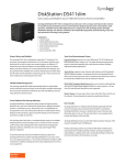
1
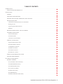
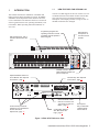
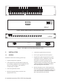
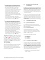
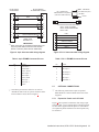
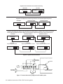
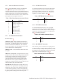
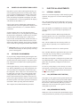
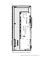
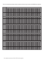
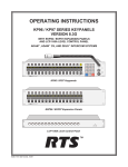
INSTALLATION INSTRUCTIONS KP96 / KP97 SERIES KEYPANELS VERSION 8.3G WITH EKP96 / EKP97 EXPANSION PANELS AND LCP-100A LEVEL CONTROL PANEL ADAM™, ADAM™ CS, AND ZEUS™ INTERCOM SYSTEMS NUM 1 HDST Listen DIR PROD RACK PL01 IFB4 TD AD NEWS SAT1 TEL1 TEL2 FLOR CHYR IS01 IS02 AUD1 IFB PHONE PREFIX 4 Clear TYPE COPY CW E-PNL 7 Talk 8 DISP AUTO 3 ISO 9 MULT CLR 0 PGM FUNC BY Matrix Intercom System KP96 / KP97 Keypanels Listen DIR PROD RACK PL01 IFB4 TD AD NEWS SAT1 TEL1 TEL2 FLOR CHYR IS01 IS02 AUD1 Clear Talk Off (Talk) Off Call Answer Talk BY Matrix Intercom System EKP96 / EKP97 Expansion Panels LCP-100A LCP-100A Level Control Panel ™ 9330-7101-001 V8.3G Rev D 11/97 Volume 6 Dyn Mic Headset PUSH Off Call Answer Incoming Messages Programing 5 RELAY EX COPY Talk Off (Talk) PL 2 SLIST PROPRIETARY NOTICE CUSTOMER SUPPORT The RTS product information and design disclosed herein were originated by and are the property of Telex Communications, Inc. Telex reserves all patent, proprietary design, manufacturing, reproduction, use and sales rights thereto, and to any article disclosed therein, except to the extent rights are expressly granted to others. Technical questions should be directed to: COPYRIGHT NOTICE Copyright 1997 by Telex Communications, Inc. All rights reserved. Reproduction in whole or in part without prior written permission from Telex is prohibited. Customer Service Department RTS/Telex, 2550 Hollywood Way, Suite 207 Burbank, CA 91505 U.S.A. Telephone: (818) 566-6700 Fax: (818) 843-7953 RETURN SHIPPING INSTRUCTIONS PROCEDURE FOR RETURNS UNPACKING AND INSPECTION Immediately upon receipt of the equipment, inspect the shipping container and the contents carefully for any discrepancies or damage. Should there be any, notify the freight company and the dealer at once. WARRANTY INFORMATION RTS products are warranted by Telex Communications, Inc. to be free from defects in materials and workmanship for a period of three years from the date of sale. The sole obligation of Telex during the warranty period is to provide, without charge, parts and labor necessary to remedy covered defects appearing in products returned prepaid to Telex. This warranty does not cover any defect, malfunction or failure caused beyond the control of Telex, including unreasonable or negligent operation, abuse, accident, failure to follow instructions in the Service Manual or the User Manual, defective or improper associated equipment, attempts at modification and repair not authorized by Telex, and shipping damage. Products with their serial numbers removed or effaced are not covered by this warranty. To obtain warranty service, follow the procedures entitled "Procedure For Returns" and "Shipping to Manufacturer for Repair or Adjustment". This warranty is the sole and exclusive express warranty given with respect to RTS products. It is the responsibility of the user to determine before purchase that this product is suitable for the user's intended purpose. ANY AND ALL IMPLIED WARRANTIES, INCLUDING THE IMPLIED WARRANTY OF MERCHANTABILITY ARE LIMITED TO THE DURATION OF THIS EXPRESS LIMITED WARRANTY. NEITHER TELEX NOR THE DEALER WHO SELLS RTS PRODUCTS IS LIABLE FOR INCIDENTAL OR CONSEQUENTIAL DAMAGES OF ANY KIND. 2 Installation Instructions, KP96 / KP97 Series Keypanels If a repair is necessary, contact the dealer where this unit was purchased. If repair through the dealer is not possible, obtain a RETURN AUTHORIZATION from: Customer Service Department Telex Communications, Inc. Telephone: (800) 828-6107 Fax: (800) 323-0498 DO NOT RETURN ANY EQUIPMENT DIRECTLY TO THE FACTORY WITHOUT FIRST OBTAINING A RETURN AUTHORIZATION. Be prepared to provide the company name, address, phone number, a person to contact regarding the repair, the type and quantity of equipment, a description of the problem and the serial number(s). SHIPPING TO MANUFACTURER FOR REPAIR OR ADJUSTMENT All shipments of RTS products should be made via United Parcel Service or the best available shipper, prepaid. The equipment should be shipped in the original packing carton; if that is not available, use any suitable container that is rigid and of adequate size. If a substitute container is used, the equipment should be wrapped in paper and surrounded with at least four inches of excelsior or similar shock-absorbing material. All shipments must be sent to the following address and must include the Return Authorization. Factory Service Department Telex Communications, Incorporated 8601 E. Cornhusker Hwy Lincoln, NE 68505 U.S.A. Upon completion of any repair the equipment will be returned via United Parcel Service or specified shipper collect. End-User License Agreement for Telex® Software IMPORTANT - Please read this document carefully before using this product. THIS DOCUMENT STATES THE TERMS AND CONDITIONS UPON WHICH TELEX COMMUNICATIONS, INC. (the COMPANY) OFFERS TO LICENSE THE INSTALLED SOFTWARE OR PROGRAM (the SOFTWARE) FOR USE WITH THE PRODUCT IN WHICH IT WAS INSTALLED. YOU ARE AGREEING TO BECOME BOUND BY THE TERMS OF THIS AGREEMENT. IF YOU DO NOT AGREE TO THE TERMS OF THIS AGREEMENT, DO NOT USE THIS PRODUCT. PROMPTLY RETURN THE PRODUCT TO THE PLACE WHERE YOU OBTAINED IT FOR A FULL REFUND. The installed software as supplied by the Company is licensed, not sold, to you for use only under the terms of this license, and the Company reserves all rights not expressly granted to you. You own the product or other media on or in which the Software is originally or subsequently recorded or fixed, but the Company retains ownership of all copies of the Software itself. 1. License: This license allows you to use the Software for internal purposes only on a single product in which it was installed. 2. Restrictions: (a) You may not market, distribute or transfer copies of the Software to others or electronically transfer or duplicate the Software. YOU MAY NOT REVERSE ENGINEER, DECOMPILE, DISASSEMBLE, MODIFY, ADAPT, TRANSLATE, RENT, LEASE OR LOAN THE SOFTWARE OR CREATE DERIVATIVE WORKS BASED ON THE SOFTWARE OR ANY ACCOMPANYING WRITTEN MATERIALS. (b) The Software and the accompanying written materials are copyrighted. Unauthorized copying of the Software, including portions thereof or the written materials, is expressly forbidden. (c) You understand that the Company may update or revise the Software and in so doing incurs no obligation to furnish such updates to you. 3. Limited Warranty: The Company does not warrant that the operation of the Software will meet your requirements or operate free from error. The Company DISCLAIMS ALL OTHER WARRANTIES AND CONDITIONS EITHER EXPRESS OR IMPLIED, INCLUDING THE WARRANTIES OF MERCHANTABILITY, FITNESS FOR A PARTICULAR PURPOSE AND NON-INFRINGEMENT OF THIRD PARTY RIGHTS. 4. Limited Liability: The liability of the Company for any claims arising out of this License based upon the Software, regardless of the form of action, shall not exceed the greater of the license fee for the Software or $50. 38109-709 Rev A 10/97 Installation Instructions, KP96 / KP97 Series Keypanels 3 This page intentionally left blank. 4 Installation Instructions, KP96 / KP97 Series Keypanels TABLE OF CONTENTS INTRODUCTION · · · · · · · · · · · · · · · · · · · · · · · · · · · · · · · · · · · · · · · · · · · · · · · · · · · · · · · · · · · · · · · 7 NEW FEATURES FOR VERSION 8.3G . . . . . . . . . . . . . . . . . . . . . . . . . . . . . . . . . . . . . . . . . . . . . . . . . 7 INSTALLATION · · · · · · · · · · · · · · · · · · · · · · · · · · · · · · · · · · · · · · · · · · · · · · · · · · · · · · · · · · · · · · · · 8 GENERAL . . . . . . . . . . . . . . . . . . . . . . . . . . . . . . . . . . . . . . . . . . . . . . . . . . . . . . . . . . . . . . . . . 8 UNPACKING AND INSPECTION . . . . . . . . . . . . . . . . . . . . . . . . . . . . . . . . . . . . . . . . . . . . . . . . . . . . 9 CHECKING THE FACTORY JUMPER AND LEVEL SETTINGS . . . . . . . . . . . . . . . . . . . . . . . . . . . . . . . . . . . 9 DIP SWITCH SETTINGS . . . . . . . . . . . . . . . . . . . . . . . . . . . . . . . . . . . . . . . . . . . . . . . . . . . . . . . . . 9 Combinations of Expansion and Level Control Panels . . . . . . . . . . . . . . . . . . . . . . . . . . . . . . . . . . . . . . . . 9 Winking On / Off . . . . . . . . . . . . . . . . . . . . . . . . . . . . . . . . . . . . . . . . . . . . . . . . . . . . . . . . . . . . 9 Logical Keypanel Address Selection . . . . . . . . . . . . . . . . . . . . . . . . . . . . . . . . . . . . . . . . . . . . . . . . . . 9 Baud Rate . . . . . . . . . . . . . . . . . . . . . . . . . . . . . . . . . . . . . . . . . . . . . . . . . . . . . . . . . . . . . . . 10 MOUNTING THE KEYPANEL AND ACCESSORIES . . . . . . . . . . . . . . . . . . . . . . . . . . . . . . . . . . . . . . . . . 10 STANDARD CONNECTIONS . . . . . . . . . . . . . . . . . . . . . . . . . . . . . . . . . . . . . . . . . . . . . . . . . . . . . . 10 Gooseneck Microphone . . . . . . . . . . . . . . . . . . . . . . . . . . . . . . . . . . . . . . . . . . . . . . . . . . . . . . . . 10 Front Panel Headset . . . . . . . . . . . . . . . . . . . . . . . . . . . . . . . . . . . . . . . . . . . . . . . . . . . . . . . . . . 10 Connection To Intercom Matrix . . . . . . . . . . . . . . . . . . . . . . . . . . . . . . . . . . . . . . . . . . . . . . . . . . . 10 OPTIONAL CONNECTIONS . . . . . . . . . . . . . . . . . . . . . . . . . . . . . . . . . . . . . . . . . . . . . . . . . . . . . . 11 Expansion Panels and LCP-100A . . . . . . . . . . . . . . . . . . . . . . . . . . . . . . . . . . . . . . . . . . . . . . . . . . . 11 Rear Panel Headset Connection . . . . . . . . . . . . . . . . . . . . . . . . . . . . . . . . . . . . . . . . . . . . . . . . . . . . 13 Terminal Block Connections . . . . . . . . . . . . . . . . . . . . . . . . . . . . . . . . . . . . . . . . . . . . . . . . . . . . . 13 EXT MIC IN Connector . . . . . . . . . . . . . . . . . . . . . . . . . . . . . . . . . . . . . . . . . . . . . . . . . . . . . . . 13 EXT LINE IN Connector . . . . . . . . . . . . . . . . . . . . . . . . . . . . . . . . . . . . . . . . . . . . . . . . . . . . . . . 13 MIC PRE OUT Connector . . . . . . . . . . . . . . . . . . . . . . . . . . . . . . . . . . . . . . . . . . . . . . . . . . . . . . 13 POWER-UP AND OPERATIONAL CHECK . . . . . . . . . . . . . . . . . . . . . . . . . . . . . . . . . . . . . . . . . . . . . . 14 KEYPANEL PROGRAMMING . . . . . . . . . . . . . . . . . . . . . . . . . . . . . . . . . . . . . . . . . . . . . . . . . . . . . 14 ELECTRICAL ADJUSTMENTS · · · · · · · · · · · · · · · · · · · · · · · · · · · · · · · · · · · · · · · · · · · · · · · · · · · · · · · 14 INTERNAL JUMPERS . . . . . . . . . . . . . . . . . . . . . . . . . . . . . . . . . . . . . . . . . . . . . . . . . . . . . . . . . . 14 J201 (EXTERNAL INPUT MUTING) . . . . . . . . . . . . . . . . . . . . . . . . . . . . . . . . . . . . . . . . . . . . . . . . 14 J202 (SPEAKER/HDST MUTE) . . . . . . . . . . . . . . . . . . . . . . . . . . . . . . . . . . . . . . . . . . . . . . . . . . . 14 J203 (SIDETONE MUTING) . . . . . . . . . . . . . . . . . . . . . . . . . . . . . . . . . . . . . . . . . . . . . . . . . . . . . 16 J401 (OUTPUT ENABLE) . . . . . . . . . . . . . . . . . . . . . . . . . . . . . . . . . . . . . . . . . . . . . . . . . . . . . . 16 J402 (BALANCE TEST) . . . . . . . . . . . . . . . . . . . . . . . . . . . . . . . . . . . . . . . . . . . . . . . . . . . . . . . 16 J403 (PREAMP OUT) . . . . . . . . . . . . . . . . . . . . . . . . . . . . . . . . . . . . . . . . . . . . . . . . . . . . . . . . 16 J404-J406 (PANEL MIC SELECTION) . . . . . . . . . . . . . . . . . . . . . . . . . . . . . . . . . . . . . . . . . . . . . . . 16 Installation Instructions, KP96 / KP97 Series Keypanels 5 AUDIO LEVEL ADJUSTMENTS . . . . . . . . . . . . . . . . . . . . . . . . . . . . . . . . . . . . . . . . . . . . . . . . . . . . 16 GENERAL . . . . . . . . . . . . . . . . . . . . . . . . . . . . . . . . . . . . . . . . . . . . . . . . . . . . . . . . . . . . . . 16 MICROPHONE PREAMPLIFIER . . . . . . . . . . . . . . . . . . . . . . . . . . . . . . . . . . . . . . . . . . . . . . . . . . 16 SPEAKER/HEADSET AMPLIFIER ADJUSTMENTS . . . . . . . . . . . . . . . . . . . . . . . . . . . . . . . . . . . . . . . 18 LIST OF FIGURES Figure 1. KP96 / KP97 Reference View · · · · · · · · · · · · · · · · · · · · · · · · · · · · · · · · · · · · · · · · · · · · · · · · · · · · 7 Figure 2. EKP96 / EKP97 Expansion Panel Reference View· · · · · · · · · · · · · · · · · · · · · · · · · · · · · · · · · · · · · · · · · · 8 Figure 3. LCP-100A Level Control Panel Reference View · · · · · · · · · · · · · · · · · · · · · · · · · · · · · · · · · · · · · · · · · · · 8 Figure 4. 9-pin Intercom cable wiring diagram · · · · · · · · · · · · · · · · · · · · · · · · · · · · · · · · · · · · · · · · · · · · · · · · 11 Figure 5. RJ-11 Intercom cable wiring diagram · · · · · · · · · · · · · · · · · · · · · · · · · · · · · · · · · · · · · · · · · · · · · · · · 11 Figure 6. Typical Interconnections · · · · · · · · · · · · · · · · · · · · · · · · · · · · · · · · · · · · · · · · · · · · · · · · · · · · · · 12 Figure 7. Terminal block wiring diagram for KP-96-RC option · · · · · · · · · · · · · · · · · · · · · · · · · · · · · · · · · · · · · · · 12 Figure 8. Locations of internal jumpers and trimmers· · · · · · · · · · · · · · · · · · · · · · · · · · · · · · · · · · · · · · · · · · · · · 15 LIST OF TABLES Table 1. DIP Switch Summary · · · · · · · · · · · · · · · · · · · · · · · · · · · · · · · · · · · · · · · · · · · · · · · · · · · · · · · · · 9 Table 2. 9-pin FRAME Connector Pin-out · · · · · · · · · · · · · · · · · · · · · · · · · · · · · · · · · · · · · · · · · · · · · · · · · · 11 Table 3. RJ-11 FRAME Connector Pin-out · · · · · · · · · · · · · · · · · · · · · · · · · · · · · · · · · · · · · · · · · · · · · · · · · · 11 Table 4. EXT MIC IN Connector Pin-out · · · · · · · · · · · · · · · · · · · · · · · · · · · · · · · · · · · · · · · · · · · · · · · · · · · 13 Table 5. EXT LINE IN Connector Pin-out · · · · · · · · · · · · · · · · · · · · · · · · · · · · · · · · · · · · · · · · · · · · · · · · · · 13 Table 6. MIC PRE OUT Connector Pin-out · · · · · · · · · · · · · · · · · · · · · · · · · · · · · · · · · · · · · · · · · · · · · · · · · · 13 Table 7. Rear Panel Headset Connector Pin-out · · · · · · · · · · · · · · · · · · · · · · · · · · · · · · · · · · · · · · · · · · · · · · · · 13 Table 8. Correspondence between address numbers and intercom port numbers for ADAM Intercom Systems · · · · · · · · · · · · · · · 20 6 Installation Instructions, KP96 / KP97 Series Keypanels 1 1.1 INTRODUCTION NEW FEATURES FOR VERSION 8.3G Version 8.3G adds support for the LCP-100A Level Control Panel and removes the MVOL feature from the Display scroll list (refer to operating instructions for a description of the Display scroll list.) Usage of some of the DIP switches has also changed. This manual describes the installation of the KP96 and KP97 Series Keypanels and their accessories, the EKP96 and EKP97 Series Expansion Panels and the LCP-100A Level Control Panel. The manual is based on version 8.3G of the keypanel firmware. For operating information, refer to the KP96 / KP97 Operating Instructions Manual, version 8.3G. Programming keypad. See operating instruction manual for details. Internal speaker is behind keypad. Talk and listen keys, with 4character alphanumeric displays. Optional panel microphone for use with internal speaker. PL NUM 1 HDST Listen DIR PROD RACK PL01 IFB4 TD AD NEWS SAT1 TEL1 TEL2 FLOR CHYR IS01 IS02 AUD1 IFB PHONE PREFIX 4 Clear TYPE COPY CW E-PNL 7 Talk 8 DISP AUTO 3 ISO Volume 6 9 Dyn Mic Headset PUSH Off Call Answer Incoming Messages Programing 5 RELAY EX COPY Talk Off (Talk) 2 SLIST MULT CLR 0 PGM FUNC BY Matrix Intercom System Headset connector. May be used instead of speaker and panel microphone. Optional KP96-RC Rear Connector Module. See “Optional Connections”, page 11 Terminal strip. See “Optional Connections”, page 11. HEADSET + AMP OUT EXPANSION PUSH + SPKR AMP SPKR GROUP OUT CALL IN IN EXT MUTE 0 22 PUSH 110 EXT MIC IN PNL EXT LINE IN MIC LEVEL CARBON DYN HDST HDST MIC PRE OUT LEVEL TO COMPR. MATRIX P11 ® TELEX COMMUNICATIONS, INC. MADE IN U.S.A. SW1 1 OPEN 8 P10 MIN I/C LEVEL MIN SPKR SIDE HDST EXT MUTE TONE MUTE SERIAL No. LEVEL SPKR HDST KP98-7 CAUTION DISCONNECT POWER BEFORE OPENING CLOSED Level trimmers provide adjustment for non-standard levels. See “Electrical Adjustments”, page 14. Choice of DE9S or RJ11 intercom connector. See “Connection to Intercom Matrix”, page 10. Configuration switches. See “DIP Switch Settings”, page 9. Fused power entry module with 110/220 voltage selector switch. Figure 1. KP96 / KP97 Reference View Installation Instructions, KP96 / KP97 Series Keypanels 7 Listen DIR PROD RACK PL01 IFB4 TD AD NEWS SAT1 TEL1 TEL2 FLOR CHYR IS01 IS02 AUD1 Clear Talk Off (Talk) Off Call Answer Talk BY Matrix Intercom System 0 22 CONTROL 110 SERIAL No. CAUTION DISCONNECT POWER BEFORE OPENING Figure 2. EKP96 / EKP97 Expansion Panel Reference View ® LCP-100A EXP. DATA IN ® EXP. DATA OUT TELEX COMMUNICATIONS, INC. Minneapolis, MN. Figure 3. LCP-100A Level Control Panel Reference View 2 INSTALLATION 5. Connect the keypanel and any accessories. 2.1 GENERAL 6. Power up the equipment and check operation. 7. Program the keypanel using the intercom system configuration software (ADAMedit or Zeus-edit). Some aspects of keypanel setup, such as key assignment, may also be performed from the keypanel using the programming keypad. Refer to the “Advanced Operation” information in the KP96 / KP97 Operating Instructions Manual. 8. Place the keypanel in service. If the keypanel keys have been assigned prior to placing the keypanel in service, the station operator should only need to refer to the “Basic Operation” information in the KP96 / KP97 Operating Instructions Manual. Installation consists of the following general steps: 1. Unpack and inspect the equipment. 2. Check that the factory default jumper positions and level settings are appropriate for your application and make any required changes. (The defaults are virtually always acceptable.) 3. Set the back panel DIP switches. 4. Mount the keypanel and any accessories in an equipment rack or bay. 8 Installation Instructions, KP96 / KP97 Series Keypanels 2.2 UNPACKING AND INSPECTION As soon as possible after receipt, inspect the container(s) and contents for physical damage that may have occurred in shipping. If damage has occurred, immediately (within 24 hours of receipt of equipment) contact the carrier involved and file a claim. Save all packing materials, and request an immediate inspection by the carrier’s insurance claims agent. Table 1. DIP Switch Summary DIP Switch Description Settings (X=Don’t care) Combinations 1, 2 Combinations of expansion and level control panels 0 EKP’s, 0 or 1 LCP 1 EKP, 0 to 2 LCP’s SW 1 SW 2 X Open Open Close 2 EKP’s, 0 to 3 LCP’s Close Close There should be one power cord for each keypanel and one gooseneck microphone for each keypanel ordered with a microphone. There should be one power cord and one interconnect cable for each expansion panel and level control panel. 3 Winking On / Off Address SW 4 SW 5 SW 6 SW 7 ☞ For information about returns to RTS, refer to the front of this manual. 2.3 CHECKING THE FACTORY JUMPER AND LEVEL SETTINGS There are several internal jumpers and level adjustments which can be changed to modify the keypanel operation and audio input/output levels. These have been set to meet the requirements of most typical situations. However, if you wish to review these settings prior to installation, refer to “Electrical Adjustments”, page 14. 2.4 Open: Winking off Closed: Winking on 4-7 8 Logical keypanel address select. Baud rate select 1 Close Open Open Open 2 Open Close Open Open 3 Close Close Open Open 4 Open Open Close Open 5 Close Open Close Open 6 Open Close Close Open 7 Close Close Close Open 8 Open Open Open Close Open: 9600 baud Closed: 76.8 kbaud (DO NOT USE!) DIP SWITCH SETTINGS The DIP switches are located on the back of the keypanel. The switch settings are summarized in Table 1 and are described in the following paragraphs. ☞ Important: Any time you change the DIP switch settings you must turn the power off-then-on to reset. 2.4.1 Combinations of Expansion and Level Control Panels Dip switches 1 and 2 select the various allowable combinations of expansion panels and level control panels that can be connected to the keypanel. 2.4.2 Winking On / Off DIP switch 3 turns the winking feature on or of. When winking is on, the LED in each listen key will wink when the talk key directly beneath it is on. This provides a visual reminder of any active talk paths. For some people, this may be distracting and the feature may be turned off. 2.4.3 Logical Keypanel Address Selection DIP switches 4-7 set the logical keypanel address, which uniquely identifies the keypanel in the intercom system. Zeus Intercom Systems: The logical keypanel addresses are the numbers 1 through 8 printed on the back panel of the Zeus frame next to the keypanel connectors. (The number s repeat for every group of 8 connectors.) As you connect each keypanel to a connector, use the number printed next to that connector to set the address. For example, if you connect a keypanel to a connector numbered 1, refer to Table 1 and set DIP switches 4 through 7 to select address 1. ADAM CS Intercom Systems: Use the appropriate planning worksheet in the ADAM CS Installation Manual. (Refer to the List of Tables in the front of the manual. The planning worksheets are listed at the bottom of the List of Tables.) Installation Instructions, KP96 / KP97 Series Keypanels 9 • ADAM CS with RJ-11 or DB-9 back panel: You can determine the correct logical keypanel address from the worksheet in either of two ways: 1) If you know the port number that a keypanel will be connected to, look up the port number in the worksheet, then read across to the appropriate logical keypanel number for that port number. 2) If you know the connector number (on the back of the ADAM CS frame) that the keypanel will be connected to, look up that connector number in the worksheet, then read across to the appropriate logical keypanel number. Once you have determined the correct logical keypanel number, refer to Table 1 and position DIP switches 4 through 7 to set this as the address. • ADAM CS frame with 50-pin Telco back panel: You can determine the correct logical keypanel address from the worksheet in either of two ways: 1) If you know the port number that a keypanel will be connected to, look up the port number in the worksheet, then read across to the appropriate logical keypanel number for that port number. 2) If you know the connector numbers and pin numbers that the keypanel will be connected to, look up these numbers in the worksheet, then read across to the appropriate logical keypanel number. Once you have determined the correct logical keypanel number, refer to Table 1 and position DIP switches 4 through 7 to set this as the address. ADAM Intercom Systems: To set the address, first refer to Table 8, page 20, and locate the intercom port number to which the keypanel will be connected. Then, read across to the “Address” column to find the logical keypanel address (it will always be a number between 1 and 8). Finally, refer to Table 1 and set the DIP switches to this address number. 2.4.4 Baud Rate SW1-8 selects the baud rate for communication with the intercom system’s configuration computer. For all ADAM, ADAM CS, and Zeus intercom systems this switch must be set to the open position (9600 baud). Do not use the 76.8 kbaud setting. 2.5 MOUNTING THE KEYPANEL AND ACCESSORIES Keypanels, expansion panels and level control panels may be mounted in any industry standard 483 mm (19") wide equipment rack or equipment bay. For all panels, allow an additional 2 to 3 inches in back for cables and connectors. No special tools other than those found in a typical tool kit are required for mounting. The panels have no special ventilation requirements. For ease of use, when positioning the panels it may help to locate each level control panel directly above or below the keypanel or expansion panel that it will be used with. Otherwise, you will have to label each LCP control knob according to the key assignment alphas on the keypanel or expansion panel. 2.6 STANDARD CONNECTIONS 2.6.1 Gooseneck Microphone If you ordered the keypanel with a gooseneck microphone, screw the microphone into the panel microphone jack on the front panel. 2.6.2 Front Panel Headset The front panel headset jack accepts a monaural, dynamic-microphone headset. Headphone impedance should be 8 to 400 ohms. Nominal microphone output should be -60 dBm, 150 ohms. Connector Type: D4F (Mates with A4M) Pin 1: Microphone Pin 2: Microphone + Pin 3: Headphone Pin 4: Headphone + 2.6.3 Connection To Intercom Matrix Use either a 9-pin or RJ-11 intercom cable (but not both) to connect to the intercom system. You can use a prefabricated cable, or construct a cable using the wiring diagram in Figure 4 or 5. Plug one end of the cable into the P10 or P11 connector on the back panel of the keypanel. Plug the other end into the appropriate port of the intercom system. (This will be the port number that you designated previously when setting the address DIP switches.) ☞ Keypanels may be connected while the intercom system is running. 10 Installation Instructions, KP96 / KP97 Series Keypanels DE-9P (MALE) TO KEYPANEL DE-9S (FEMALE) TO INTERCOM SYSTEM* + - 1 + - 4 AUDIO TO MATRIX + 7 AUDIO FROM MATRIX 1 DATA 2 6 4 5 9 7 8 3 RJ 11 MOD PLUG AMP 55550423 or equivalent (View from cable entrance) Use AMP Crimp Tool 12316661 LATCH 2 6 3 TWISTED PAIR TELEPHONE CABLE PAIR 1: AUDIO TO MATRIX PAIR 2: AUDIO FROM MATRIX PAIR 3: DATA 5 9 8 3 CABLE TYPE: BELDEN 8777 * CONTACTS 123456 IMPORTANT! When connecting to an ADAM CS back panel, use only low-profile cable connectors such as AMP Part No. 747516-3 (Telex Part No. 59926-678) DATA - 1 AUDIO FROM MATRIX + 2 AUDIO TO MATRIX + 3 AUDIO TO MATRIX - 4 AUDIO FROM MATRIX - 5 DATA + 6 1 2 3 4 5 6 Figure 4. 9-pin Intercom cable wiring diagram Figure 5. RJ-11 Intercom cable wiring diagram Table 2. 9-pin FRAME Connector Pin-out Table 3. RJ-11 FRAME Connector Pin-out Pin Function 1 RS422 Data “+” 2 RS 422 Data “-” 3 Ground , Shield 4 Audio Output “+” 5 Audio Output “-” 6 Pin Function 1 RS422 Data “-” 2 Audio Input “+” 3 Audio Output “+” 4 Audio Output “-” Ground, Shield 5 Audio Input “-” 7 Audio Input “-” 6 RS422 Data “+” 8 Audio Input “+” 9 Ground 2.7 ☞ Note that 9-pin intercom cables for use with an ADAM CS frame must use special connectors at the intercom matrix end as shown in Figure 4. OPTIONAL CONNECTIONS ☞ The following connections require an optional KP96-RC Rear Connector Panel on the back of the keypanel. 2.7.1 Expansion Panels and LCP-100A Figure 6 shows optional connections when using expansion panel and / or level control panels with the keypanel. Use the cables supplied with the panels. A maximum of two expansion panels and three level control panels may be connected. Installation Instructions, KP96 / KP97 Series Keypanels 11 Keypanel with LCP-100A Level Control Panel Only LCP-100A KEYPANEL EXPANSION EXP. DATA IN EXP. DATA OUT Keypanel with Expansion Panels only. Note: Do not exceed 2 expansion panels. KEYPANEL EXPANSION PANEL EXPANSION PANEL CONTROL CONTROL EXPANSION Keypanel with Expansion Panels and LCP-100A Level Control Panels. Always connect the Level Control Panels after the Expansion Panels. Note: Do not exceed 2 expansion panels and 3 level control panels. KEYPANEL EXPANSION PANEL 1 EXPANSION PANEL 2 CONTROL CONTROL LCP-100A Adjusts Expansion Panel 1 Levels LCP-100A Adjusts Expansion Panel 2 Levels EXPANSION LCP-100A Adjusts Keypanel Levels EXP. DATA IN EXP. DATA OUT EXP. DATA IN EXP. DATA OUT EXP. DATA IN EXP. DATA OUT Figure 6. Typical Interconnections INTERNAL SPEAKER + + – – AMP SPKR AMP SPKR GROUP OUT IN OUT IN CALL TS1 TERMINAL BLOCK EXTERNAL SPEAKER 1 2 3 4 5 DRIVER EXT. MUTE 6 JUMPER JUMPER 7 EXTERNAL DRIVER DEVICE CIRCUIT FOOT SWITCH Figure 7. Terminal block wiring diagram for KP-96-RC option 12 Installation Instructions, KP96 / KP97 Series Keypanels 2.7.2 Rear Panel Headset Connection Table 7 lists the HEADSET connector pin functions. A variety of headset types can be connected. Headset/speaker switching can also be accomplished from this connector. When the front panel HDST switch is in the off position, shorting pins 7 and 8 on the rear panel headset connector will cause the headset to activate, and the front panel speaker and microphone will turn off. 2.7.4 EXT MIC IN Connector An external microphone can be connected. The external microphone may be used with or without a front panel gooseneck microphone of the same type. (Internal keypanel jumpers J404-J406 must be set for the type of microphone (see "Internal Jumpers", page 14). Table 4. EXT MIC IN Connector Pin-out Table 7. Rear Panel Headset Connector Pin-out Pin Pin Function 1 Dynamic mic “+” input 2 Dynamic mic common (shield) 3 Carbon mic “+” input 4 Carbon mic common 5 Headphone “+” 6 Dynamic mic “-” input 7 HDST switch control 8 HDST switch common 9 Headphone common 2.7.5 Function 1 Shield 2 Mic in “+” 3 Mic in “-” EXT LINE IN Connector An external balanced audio source, such as program sound, can be connected. The input is calibrated for a nominal line level of +8dBu. This level can be changed if required. See "Line Input to Speaker Level Adjustment", page 18, for further information. Table 5. EXT LINE IN Connector Pin-out 2.7.3 Terminal Block Connections Pin (Reference Figure 7) AMP OUT + and - : These terminals provide the keypanel audio amplifier output signal to drive an 8-ohm, 3watt speaker. As supplied from the factory, jumpers connect these terminals to the SPKR IN + and - terminals. Remove these jumpers only if the keypanel audio output is to be redirected to an external speaker. SPKR IN + and - : These terminals connect to the internal speaker. GRP CALL (Group Call): As supplied from the factory, a jumper connects this terminal to the ground terminal for normal Talk key operation. For external group call, remove the jumper, and connect a normally open foot switch between this terminal and the ground terminal. When the foot switch is pressed, all Talk keys that are latched in the up position will be activated. When the foot switch is released, they will be deactivated. 2.7.6 Function 1 Shield 2 Line in “+” 3 Line in “-” MIC PRE OUT Connector This connector provides a balanced mic output signal of +8 dBu at 60 ohms. As supplied, the MIC PRE OUT signal is activated only when any Talk key is on. If you want this output to be on continuously, you must reset internal jumper J403 (see "Internal Jumpers", page 14). Table 6. MIC PRE OUT Connector Pin-out Pin Function 1 Shield 2 Mic out “+” 3 Mic out “-” EXT MUTE: This terminal may be used to drive an external device at no greater than 2 mA sinking current. Its normal logic state is low (0 Vdc). It shifts to logic high (+5Vdc) when any Talk key is pressed. This signal may be used, for example, to mute a monitor speaker when the keypanel operator is talking on the intercom system. Installation Instructions, KP96 / KP97 Series Keypanels 13 2.8 POWER-UP AND OPERATIONAL CHECK Plug in the ac power cords on the keypanel and any connected expansion panels and level control panels. When power is applied, all alphanumeric displays will first display asterisks (****) then dashes (----). After a few moments, the Talk key assignments will display. If no Talk key assignments have yet been programmed, the displays will continue to show dashes (----). If the keypanel cannot establish data communications with the intercom system, the alphanumeric displays will continue to show asterisks (****). Check the data line connections. Several symptoms may occur if the logical keypanel number is incorrectly set: 1) the keypanel may not display the expected key assignments; 2) there may be no indication when there is an incoming call; 3) when a key is pressed to talk, the destination may not hear the audio, or may hear audio from a different intercom station; 4) the displays may behave erratically. If any of these symptoms occur, recheck the logical keypanel number DIP switches. ☞ Important! Always reset the keypanel after changing the DIP switch settings. Do this by briefly removing power to the keypanel. 2.9 KEYPANEL PROGRAMMING If you previously configured the keypanel using the intercom system configuration software, it should be ready for operation. Refer the station operator to the “Basic Operation” instructions in the KP96 / KP97 Operating Instructions Manual. If the keypanel has not yet been configured you can do so now. Run the ADAMedit or Zeus-edit configuration software. By default, the configuration software starts up in the “Keypanels / Ports” setup screen. For assistance with keypanel setup, press the F1 key on the computer while viewing that screen. Once you have configured the keypanel as instructed and sent the changes to the intercom system, the keypanel should be ready for operation. Refer the station operator to the “Basic Operation” instructions in the KP96 / KP97 Operating Instructions Manual. This completes the standard installation procedures. 3 ELECTRICAL ADJUSTMENTS 3.1 INTERNAL JUMPERS There are several internal jumpers which modify keypanel operation. The jumpers are set for the following default operations: J201: The EXT LINE IN signal (KP-96-RC option only) is muted when any Talk key is pressed. May be optionally set for no mute. J202: The speaker (or headphones) are muted by 15 dB when any Talk key is pressed. May be optionally set to full mute. J203: Continuous sidetone. When using a headset, the keypanel operators own voice will be heard at all times in the headphones. May be optionally set for sidetone only during talk. J401: The microphone activates when any Talk key is pressed. May be optionally set for continuous microphone. J402: Normal/test switch set for normal operation. J403: The MIC PRE OUT signal (KP-96-RC option only) is activated only when any Talk key is pressed. May be optionally set for continuous operation. J404-J406: The keypanel is configured for operation with the standard dynamic, -70dB, 150-ohm gooseneck microphone. May be optionally configured for other microphone types. To reset any of the jumpers, remove the top cover from the keypanel. Locations of the jumpers are shown in Figure 8. The following paragraphs describe the alternative settings for the jumpers. 3.1.1 J201 (EXTERNAL INPUT MUTING) This jumper is only significant in keypanels that have the KP-96-RC Rear Connector Plate option installed. When pins 2 and 3 are shorted, a signal input at the EXT LINE IN connector is muted when any Talk key is pressed. When pins 1 and 2 are shorted, the signal is not muted during Talk key activation. 3.1.2 J202 (SPEAKER/HDST MUTE) When pins 1 and 2 are shorted, the speaker/headset signal is fully muted when any Talk keys are pressed. When pins 14 Installation Instructions, KP96 / KP97 Series Keypanels Figure 8. Locations of internal jumpers and trimmers Installation Instructions, KP96 / KP97 Series Keypanels 15 J405 RV401 RV407 RV402 P4 J406 J404 RV403 RV404 P5 RV405 RV408 RV406 J403 J402 RV409 J401 TP 407 U302 1 SW1 Y301 8 U314 U305 U309 P10 U203 J203 RV206 RV209 RV203 P2 RV205 P11 RV202 J201 RV204 RV201 P6 J202 Q402 RV208 RV207 P1 2 and 3 are shorted, the signal is muted by 15 dB when any Talk keys are pressed. 3.1.3 J401 (OUTPUT ENABLE) When the jumper is installed, the microphone is on only when any Talk key is pressed. When the jumper is removed, the microphone will always be on. 3.1.5 J402 (BALANCE TEST) For normal operation, there should be no jumper installed. This jumper is used when adjusting the keypanel audio levels. See “Balance Adjustment”, page 17. 3.1.6 3.2.1 GENERAL The following paragraphs describe the procedures to calibrate the output level to the factory standard of +8 dBu. If a different level is required, substitute that level for +8 dBu. Most audio level trimmers are accessible through access holes on the back of the keypanel. Each trimmer access hole is labeled with its function. Some trimmers are internal, and can only be accessed with the top cover removed. Locations of trimmers are shown in Figure .8 Audio levels may be adjusted with the panel disconnected from the intercom system. However, proper operation should be confirmed when the panel is reconnected. If levels change after reconnection, check the intercom system wiring for one-sided shorts to ground, wiring errors, or unintended terminations. J403 (PREAMP OUT) This jumper is only significant in keypanels that have the KP-96-RC Rear Connector Plate option installed. When pins 1 and 2 are shorted, the mic signal at the MIC PRE OUT connector is switched on and off by the Talk keys. When pins 2 and 3 are shorted, the mic signal at the MIC PRE OUT connector is always on. 3.1.7 AUDIO LEVEL ADJUSTMENTS J203 (SIDETONE MUTING) When pins 1 and 2 are shorted, the sidetone signal is always on. When pins 2 and 3 are shorted, the sidetone signal is on only when a Talk key is pressed. 3.1.4 3.2 J404-J406 (PANEL MIC SELECTION) These jumpers work together to configure the panel microphone preamp for various types of microphones as follows: 2-Wire Electret: J404 Pins 1 and 2 shorted J405 No jumper J406 No jumper 3-Wire Electret: J404 No jumper J405 No jumper J406 No jumper The following procedures make use of the additional connectors available on the KP-96-RC Rear Connector Plate option. Connector pin-outs for these connectors were presented earlier in this section. If the keypanel under adjustment does not have these connectors, refer to drawing number IKP-950/2-5 (in the Keypanel Drawings and Parts Manual). The IKP-950/2-5 drawing shows equivalent locations where test equipment may be connected. Required test equipment: Audio Signal Generator with balanced output Audio Signal Analyzer with balanced input DC Millivoltmeter Oscilloscope - any commercially available type 3.2.2 1. Set the HDST switch to off. 2. Remove the gooseneck microphone, and insert a -70 dBm signal (1KHz at 150 ohms) into the microphone connector. Or use the EXT MIC IN connector with the front panel microphone removed (ref Table 4, page 13 for pin-out). 3. Activate the microphone by setting a Talk key to the latched-up position. Balanced Dynamic (-70 dB, 150 ohms): J404 Pins 2 and 3 shorted J405 Pins 1 and 2 shorted J406 Pins 1 and 2 shorted 16 Installation Instructions, KP96 / KP97 Series Keypanels MICROPHONE PREAMPLIFIER 4. Check the level at the MIC PRE OUT connector (ref Table 6 for pin-out). It should measure +8 dBu. 5. If the reading is not +8 dBu, but within a 3dB range, adjust the LEVEL TO MATRIX trimmer (RV406) for +8dBu. 6. If the reading is more than 3 dB from +8 dBu, or another output level is used by your facility, proceed to paragraph to begin the mic preamp calibration procedures. 2-3; J405 short pins 1-2; J406 short pins 1-2. (This is the default microphone configuration.) 2. Insert a -70dBm signal (1 KHz at 150 ohms) into the gooseneck microphone connector. Or use the EXT MIC IN connector (with the front panel microphone removed). 3. Adjust the PNL trimmer (RV401) for +8dBu at the MIC PRE OUT connector. 4. Insert a common mode signal (120 Hz, -70 dBm) into the gooseneck microphone connector, or into the EXT MIC IN connector. 7. Check the frequency response from 200 Hz to 15 KHz. It should be within 1 dB. 8. Check the input noise. It should be at least -70 dB below +8 dBu. 5. Adjust RV402 (internal) for a minimum common mode signal at the MIC PRE OUT connector. 9. Check the Total Harmonic Distortion (THD) from 200 Hz to 15KHz at +18 dBu output. It should be less than or equal to 0.15 percent. 6. Reinsert a -70dBm signal. 7. Remove the shorting plug across J401 (causes continuous mic activation). 8. Monitor the level at the audio output pins of the FRAME connector, P10 (reference Table - for pin-out). The output level should be +8dBu. 9. Remove the signal from the mic input, and reinstall the shorting plug across J401. Balance Adjustment 1. Turn the COMPR trimmer (RV405) fully counterclockwise. This sets the compressor circuit to minimum (compressor ratio of 1:1). 2. Measure and record the dc voltage at test point TP407. 3. Install a shorting plug across J402. 4. Measure the dc voltage at TP407, and adjust RV408 (internal) to match (within 5 mV) the previously recorded voltage. 5. Remove the shorting plug at J402. Headset Dynamic-Mic Level 1. Insert a -60dBm signal (1 KHz at 150 ohms) into the dynamic mic input of the HEADSET connector (reference Table 7, page 13 for pin-out). 2. Activate the HDST key on the front of the keypanel. 3. Monitor the signal level at the MIC PRE OUT connector. It should be +8 dBu. If not, adjust the DYN HDST trimmer (RV403) to achieve an output reading of +8 dBu. Tone Generator Level Adjustment 1. Activate the 400 Hz tone generator in the keypanel (enter 0-8-7 on the keypad). 4. 2. Adjust the LEVEL TO MATRIX trimmer (RV406) for a +8dBu tone output level at the MIC PRE OUT connector. Insert a common mode signal into the dynamic mic input of the HEADSET connector. 5. Adjust RV404 (internal) for a minimum common mode signal at the MIC PRE OUT connector. Turn off the tone generator (press CLR on the keypad). 6. Remove the signal at the dynamic mic input. 3. Panel Mic Level Adjustment 1. Configure the J404-J406 jumper blocks for a balanced dynamic panel microphone: J404 short pins Installation Instructions, KP96 / KP97 Series Keypanels 17 Headset Carbon-Mic Level 1. Insert a -25dBm signal (1 KHz at 50 ohms) into the carbon mic input of the HEADSET connector (reference Table 7 for pin-out). ☞ A +12 vdc bias voltage is supplied at pin 3 (carbon mic + input) of the HEADSET connector. The signal generator should be isolated from this dc bias voltage. 2. Activate the HDST key on the front of the keypanel. 3. Monitor the signal level at the MIC PRE OUT connector. It should be +8 dBu. If not, adjust the CARBON HDST trimmer (RV407) to achieve an output reading of +8 dBu. 4. 3. Remove the keypanel audio connection from the intercom matrix. 4. Insert a +8dBu (1 KHz) signal into the audio input + and - pins of the FRAME connector, P10 (Table 2, page 11). 5. Turn the front panel HDST switch off. 6. Turn the front panel intercom audio level control (outer knob) fully clockwise (maximum volume). 7. Adjust the SPKR trimmer (RV207) to measure 4.9VRMS (3 watts) at the audio analyzer. There should be no clipping of the output signal. 8. Turn the front panel intercom audio level control fully counterclockwise (minimum volume). Adjust the MIN I/C trimmer (RV202) to measure -30 dB below the 4.9VAC reference level. 9. Readjust the front panel intercom audio level control to again measure 4.9VAC at the audio analyzer. Remove the signal from the carbon mic input. Compressor/AGC Setup 1. 2. Insert a -60 dBm signal (1 KHz at 150 ohms) into the front panel microphone connector. Or use the EXT MIC IN connector (with the front panel microphone removed). Adjust the COMPR trimmer (RV405) to measure +13dBu at the audio output of the FRAME connector, P10. 10. Insert a 1 KHz common mode signal into the audio input + and - pins of the FRAME connector. 11. Adjust RV201 (internal) for a minimum common mode signal. 12. Remove the signal from the FRAME connector. 3. Reduce the input signal level to -80 dBm. 4. Adjust RV409 (internal) for a +4 dBu audio output level at the FRAME connector. 5. Perform this procedure several times to optimize the compression ratio accuracy. This will test compression at a 2:1 ratio (0.5dBu). Confirm correct operation of the compression circuit by increasing and reducing input levels and measuring output ratio accordingly. 3.2.3 SPEAKER/HEADSET AMPLIFIER ADJUSTMENTS Line Input-to-Speaker Gain Adjustment 1. Install a shorting plug across J201, pins 2 and 3. 2. Insert a +8dBu (1 KHz) signal into the EXT LINE IN connector (reference Table 5, page 13, for pin-out). 3. The HDST switch should be off. 4. Turn the line input level control (inner knob on the front panel) fully counterclockwise. 5. Adjust the MIN EXT trimmer (RV205) to measure -30 dB below a reference level of 4.9VAC level at the audio analyzer connected to the amplifier output. 6. Readjust the line input level control to measure 4.9VAC output at the audio analyzer. 7. Insert a 1KHz common mode signal into the EXT LINE IN connector. Matrix-to-Speaker Gain 1. Disconnect the loudspeaker (either internal or external) from the + AMP OUT and - AMP OUT terminals on the back of the keypanel. 2. Terminate the + AMP OUT and - AMP OUT terminals with an 8-ohm, 10-watt resistive load. Connect an audio analyzer across the load. 18 Installation Instructions, KP96 / KP97 Series Keypanels 8. Adjust RV204 (internal) for a minimum common mode signal. 9. Insert a +8dBu (1 KHz) signal into the EXT LINE IN connector and record the output reading. 10. Remove the signal from the EXT LINE IN connector, and insert it into the audio input + and - pins of the FRAME connector, P10. 11. Remove the shorting plug from jumper block J201. The output reading should be the same as in step 9. Sidetone Level Adjust 1. Install a shorting plug across pins 1-2 of J203. 2. Insert a -70dBm signal (1KHz at 150 ohms) into the dynamic mic input of the HEADSET connector . 3. Turn on the HDST switch, and monitor the signal level across the 8-ohm load at the headphone output of the HEADSET connector. 4. Adjust the SIDETONE trimmer (RV209) to 35 dB below a 2V AC reference level. (The level may be varied according to user preference.) 5. Remove the test equipment. Speaker Muting Setup 1. Short pins 2 and 3 of jumper block J202. 2. Insert a +8dBu signal (1 KHz) into the audio input pins of the FRAME connector, P10. 3. Alternately activate and deactivate a front panel Talk key while adjusting the SPKR MUTE trimmer (RV203) to provide 15dB muting at the + AMP OUT and - AMP OUT terminals during Talk switch activation. 4. Short pins 1 and 2 of J202. Insert a +8dBu signal (1 KHz) into the audio input of the FRAME connector. 5. Activate a front panel Talk key, and check that the amplifier output is fully muted. Restore the J202 shorting plug to pins 2-3. 6. Remove the 8-ohm load from the amplifier output, and reconnect the speaker. Headphone Level Adjust 1. Terminate the headphone output of the HEADSET connector (pins 5 and 9) with an 8-ohm, 10-watt resistive load. Connect an audio analyzer across the load. 2. Set the front panel HDST switch to on. 3. Insert a +8dBu signal (1 KHz) into the audio input of the FRAME connector. 4. Adjust the HDST trimmer (RV208) for 2VRMS (500 milliwatts) at the headphone output. 5. Set the front panel HDST switch to off. 6. Adjust the HDST MUTE trimmer (RV206) for 6dB muting below the 2V AC reference level. Installation Instructions, KP96 / KP97 Series Keypanels 19 Table 8. Correspondence between address numbers and intercom port numbers for ADAM Intercom Systems Address Intercom Port Numbers (8 Ports per Audio I/O Card) 1 1 9 17 25 33 41 49 57 65 73 81 89 97 105 113 121 129 137 145 153 161 169 177 185 193 2 2 10 18 26 34 42 50 58 66 74 82 90 98 106 114 122 130 138 146 154 162 170 178 186 194 3 3 11 19 27 35 43 51 59 67 75 83 91 99 107 115 123 131 139 147 155 163 171 179 187 195 4 4 12 20 28 36 44 52 60 68 76 84 92 100 108 116 124 132 140 148 156 164 172 180 188 196 5 5 13 21 29 37 45 53 61 69 77 85 93 101 109 117 125 133 141 149 157 165 173 181 189 197 6 6 14 22 30 38 46 54 62 70 78 86 94 102 110 118 126 134 142 150 158 166 174 182 190 198 7 7 15 23 31 39 47 55 63 71 79 87 95 103 111 119 127 135 143 151 159 167 175 183 191 199 8 8 16 24 32 40 48 56 64 72 80 88 96 104 112 120 128 136 144 152 160 168 176 184 192 200 1 201 209 217 225 233 241 249 257 265 273 281 289 297 305 313 321 329 337 345 353 361 369 377 385 393 2 202 210 218 226 234 242 250 258 266 274 282 290 298 306 314 322 330 338 346 354 362 370 378 386 394 3 203 211 219 227 235 243 251 259 267 275 283 291 299 307 315 323 331 339 347 355 363 371 379 387 395 4 204 212 220 228 236 244 252 260 268 276 284 292 300 308 316 324 332 340 348 356 364 372 380 388 396 5 205 213 221 229 237 245 253 261 269 277 285 293 301 309 317 325 333 341 349 357 365 373 381 389 397 6 206 214 222 230 238 246 254 262 270 278 286 294 302 310 318 326 334 342 350 358 366 374 382 390 398 7 207 215 223 231 239 247 255 263 271 279 287 295 303 311 319 327 335 343 351 359 367 375 383 391 399 8 208 216 224 232 240 248 256 264 272 280 288 296 304 312 320 328 336 344 352 360 368 376 384 392 400 1 401 409 417 425 433 441 449 457 465 473 481 489 497 505 513 521 529 537 545 553 561 569 577 585 593 2 402 410 418 426 434 442 450 458 466 474 482 490 498 506 514 522 530 538 546 554 562 570 578 586 594 3 403 411 419 427 435 443 451 459 467 475 483 491 499 507 515 523 531 539 547 555 563 571 579 587 595 4 404 412 420 428 436 444 452 460 468 476 484 492 500 508 516 524 532 540 548 556 564 572 580 588 596 5 405 413 421 429 437 445 453 461 469 477 485 493 501 509 517 525 533 541 549 557 565 573 581 589 597 6 406 414 422 430 438 446 454 462 470 478 486 494 502 510 518 526 534 542 550 558 566 574 582 590 598 7 407 415 423 431 439 447 455 463 471 479 487 495 503 511 519 527 535 543 551 559 567 575 583 591 599 8 408 416 424 432 440 448 456 464 472 480 488 496 504 512 520 528 536 544 552 560 568 576 584 592 600 1 601 609 617 625 633 641 649 657 665 673 681 689 697 705 713 721 729 737 745 753 761 769 777 785 793 2 602 610 618 626 634 642 650 658 666 674 682 690 698 706 714 722 730 738 746 754 762 770 778 786 794 3 603 611 619 627 635 643 651 659 667 675 683 691 699 707 715 723 731 739 747 755 763 771 779 787 795 4 604 612 620 628 636 644 652 660 668 676 684 692 700 708 716 724 732 740 748 756 764 772 780 788 796 5 605 613 621 629 637 645 653 661 669 677 685 693 701 709 717 725 733 741 749 757 765 773 781 789 797 6 606 614 622 630 638 646 654 662 670 678 686 694 702 710 718 726 734 742 750 758 766 774 782 790 798 7 607 615 623 631 639 647 655 663 671 679 687 695 703 711 719 727 735 743 751 759 767 775 783 791 799 8 608 616 624 632 640 648 656 664 672 680 688 696 704 712 720 728 736 744 752 760 768 776 784 792 800 1 801 809 817 825 833 841 849 857 865 873 881 889 897 905 913 921 929 937 945 953 961 969 977 985 993 2 802 810 818 826 834 842 850 858 866 874 882 890 898 906 914 922 930 938 946 954 962 970 978 986 994 3 803 811 819 827 835 843 851 859 867 875 883 891 899 907 915 923 931 939 947 955 963 971 979 987 995 4 804 812 820 828 836 844 852 860 868 876 884 892 900 908 916 924 932 940 948 956 964 972 980 988 996 5 805 813 821 829 837 845 853 861 869 877 885 893 901 909 917 925 933 941 949 957 965 973 981 989 997 6 806 814 822 830 838 846 854 862 870 878 886 894 902 910 918 926 934 942 950 958 966 974 982 990 998 7 807 815 823 831 839 847 855 863 871 879 887 895 903 911 919 927 935 943 951 959 967 975 983 991 999 8 808 816 824 832 840 848 856 864 872 880 888 896 904 912 920 928 936 944 952 960 968 976 984 992 1000 20 Installation Instructions, KP96 / KP97 Series Keypanels NOTES Installation Instructions, KP96 / KP97 Series Keypanels 21 ™