1
AR-PB2A
CODE: 00ZARPB2A//1E
DIGITAL COPIER OPTION
PRINTER UNIT
MODEL
AR-PB2A
CONTENTS
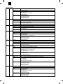
[ 1 ] SYSTEM CONFIGURATION . . . . . . . . . . . . . . . . . . . . . . . . . . . 1-1
[ 2 ] SPECIFICATION . . . . . . . . . . . . . . . . . . . . . . . . . . . . . . . . . . . . 2-1
[ 3 ] SETUP . . . . . . . . . . . . . . . . . . . . . . . . . . . . . . . . . . . . . . . . . . . . 3-1
[ 4 ] SETTING AND ADJUSTMENTS . . . . . . . . . . . . . . . . . . . . . . . . 4-1
[ 5 ] CONFIGURATION REPORT AND TEST PAGE . . . . . . . . . . . . 5-1
[ 6 ] FIRMWARE VERSION UP . . . . . . . . . . . . . . . . . . . . . . . . . . . . 6-1
[ 7 ] FUNCTION AND OPERATION . . . . . . . . . . . . . . . . . . . . . . . . . 7-1
CIRCUIT DIAGRAM (Refer to the AR-PB2 Service Manual)
PARTS GUIDE
This document has been published to be used
for after sales service only.
The contents are subject to change without notice.
AR-PB2A
CONTENTS
[ 1 ] SYSTEM CONFIGURATION . . . . . . . . . . . . . . . . . . . . .1-1
1.
2.
Hardware . . . . . . . . . . . . . . . . . . . . . . . . . . . . . . . . . . . .1-1
A. Main Unit . . . . . . . . . . . . . . . . . . . . . . . . . . . . . . . . . .1-1
B. System Elements . . . . . . . . . . . . . . . . . . . . . . . . . . .1-1
C. Input/Output Device Options . . . . . . . . . . . . . . . . . . .1-1
D. Accessory and Options . . . . . . . . . . . . . . . . . . . . . . .1-2
E. List of the Applicable Models for the AR-PB2A
Printer Expansion Kit . . . . . . . . . . . . . . . . . . . . . . . .1-2
Software Configuration . . . . . . . . . . . . . . . . . . . . . . . . . .1-3
[ 4 ] SETUP AND ADJUSTMENTS . . . . . . . . . . . . . . . . . . . . 4-1
1.
2.
3.
[ 2 ] SPECIFICATION . . . . . . . . . . . . . . . . . . . . . . . . . . . . . . . .2-1
1.
2.
General Specification . . . . . . . . . . . . . . . . . . . . . . . . . . .2-1
A. PS Specification . . . . . . . . . . . . . . . . . . . . . . . . . . . .2-1
B. Printer Driver Compatibility . . . . . . . . . . . . . . . . . . . .2-1
Printing Function Specification . . . . . . . . . . . . . . . . . . . .2-2
A. Outline . . . . . . . . . . . . . . . . . . . . . . . . . . . . . . . . . . . .2-2
B. Details . . . . . . . . . . . . . . . . . . . . . . . . . . . . . . . . . . . .2-4
[ 3 ] SETUP . . . . . . . . . . . . . . . . . . . . . . . . . . . . . . . . . . . . . . . . .3-1
1.
2.
3.
4.
5.
6.
7.
Parts list . . . . . . . . . . . . . . . . . . . . . . . . . . . . . . . . . . . . .3-1
Preliminary work . . . . . . . . . . . . . . . . . . . . . . . . . . . . . . .3-1
Hardware setup . . . . . . . . . . . . . . . . . . . . . . . . . . . . . . .3-1
A. Common work . . . . . . . . . . . . . . . . . . . . . . . . . . . . . .3-1
B. Stand-alone environment
(Printer (parallel) cable connection) . . . . . . . . . . . . .3-3
C. Network environment
(Network card installation) . . . . . . . . . . . . . . . . . . . . .3-4
Setup on the copier side . . . . . . . . . . . . . . . . . . . . . . . . .3-4
A. Setup by simulation . . . . . . . . . . . . . . . . . . . . . . . . . .3-4
B. Setup by key operator program . . . . . . . . . . . . . . . . .3-4
Software installation and setup . . . . . . . . . . . . . . . . . . . .3-4
Setup under network environment . . . . . . . . . . . . . . . . .3-4
A. Outline of the NW Setup . . . . . . . . . . . . . . . . . . . . . .3-4
B. Checking the Hardware and Software
Requirements . . . . . . . . . . . . . . . . . . . . . . . . . . . . . .3-5
C. Confidential Print . . . . . . . . . . . . . . . . . . . . . . . . . . . .3-5
D. Tandem Print . . . . . . . . . . . . . . . . . . . . . . . . . . . . . . .3-5
Web Page Setting . . . . . . . . . . . . . . . . . . . . . . . . . . . . . .3-5
A. Password Setting . . . . . . . . . . . . . . . . . . . . . . . . . . .3-5
B. E-mail Setup and Network Scanning Setup . . . . . . .3-5
Configuration setting . . . . . . . . . . . . . . . . . . . . . . . . . . . 4-1
A. Printer setting . . . . . . . . . . . . . . . . . . . . . . . . . . . . . . 4-2
B. Interface Settings . . . . . . . . . . . . . . . . . . . . . . . . . . . 4-2
C. Network Settings . . . . . . . . . . . . . . . . . . . . . . . . . . . . 4-2
D. Print Test Page . . . . . . . . . . . . . . . . . . . . . . . . . . . . . 4-3
E. Initialization and/or Storage Setting . . . . . . . . . . . . . 4-3
Key operator programs . . . . . . . . . . . . . . . . . . . . . . . . . . 4-3
Hardware setup and adjustments . . . . . . . . . . . . . . . . . . 4-4
A. Flash Memory write protect setting . . . . . . . . . . . . . . 4-4
B. Laser power setup . . . . . . . . . . . . . . . . . . . . . . . . . . 4-4
C. Centro interface adjustment . . . . . . . . . . . . . . . . . . . 4-4
D. NVRAM clear . . . . . . . . . . . . . . . . . . . . . . . . . . . . . . 4-4
E. Network card check . . . . . . . . . . . . . . . . . . . . . . . . . 4-4
[ 5 ] Configuration Report and Test Page . . . . . . . . . . . . . 5-1
1.
2.
Samples . . . . . . . . . . . . . . . . . . . . . . . . . . . . . . . . . . . . . 5-1
Description of Each contents . . . . . . . . . . . . . . . . . . . . . 5-1
A. Hardware Status . . . . . . . . . . . . . . . . . . . . . . . . . . . . 5-1
B. Software Information . . . . . . . . . . . . . . . . . . . . . . . . . 5-3
[ 6 ] FIRMWARE VERSION UP . . . . . . . . . . . . . . . . . . . . . . . 6-1
1.
2.
Printer controll PWB . . . . . . . . . . . . . . . . . . . . . . . . . . . . 6-1
A. Cases where flash memory rewriting is required . . . 6-1
B. Necessary tools . . . . . . . . . . . . . . . . . . . . . . . . . . . . 6-1
C. Procedure . . . . . . . . . . . . . . . . . . . . . . . . . . . . . . . . . 6-1
Network card . . . . . . . . . . . . . . . . . . . . . . . . . . . . . . . . . 6-1
A. Check the version number of the network card. . . . . 6-1
B. Upgrade of network card The upgrade tool is
included in the PRINTER UTILITIES CD-ROM. . . . . 6-1
[ 7 ] FUNCTION AND OPERATION . . . . . . . . . . . . . . . . . . . 7-1
1.
2.
3.
4.
5.
6.
7.
13.
14.
15.
16.
Multi Function . . . . . . . . . . . . . . . . . . . . . . . . . . . . . . . . . 7-1
Printer Operation / Message Display . . . . . . . . . . . . . . . 7-2
Emulation Switch . . . . . . . . . . . . . . . . . . . . . . . . . . . . . . 7-3
Resolution . . . . . . . . . . . . . . . . . . . . . . . . . . . . . . . . . . . 7-3
Font . . . . . . . . . . . . . . . . . . . . . . . . . . . . . . . . . . . . . . . . 7-3
A. Downloadable Font Types . . . . . . . . . . . . . . . . . . . . 7-3
B. Location of Font Data . . . . . . . . . . . . . . . . . . . . . . . . 7-3
Language . . . . . . . . . . . . . . . . . . . . . . . . . . . . . . . . . . . . 7-3
A. Language Selection . . . . . . . . . . . . . . . . . . . . . . . . . 7-3
B. Job, control . . . . . . . . . . . . . . . . . . . . . . . . . . . . . . . . 7-3
Host I/O Port Selection . . . . . . . . . . . . . . . . . . . . . . . . . . 7-3
Memory Configuration . . . . . . . . . . . . . . . . . . . . . . . . . . 7-4
Printer control PWB switch (short pin) and
LED display . . . . . . . . . . . . . . . . . . . . . . . . . . . . . . . . . . 7-4
Confidential Print . . . . . . . . . . . . . . . . . . . . . . . . . . . . . . 7-5
Tandem Print . . . . . . . . . . . . . . . . . . . . . . . . . . . . . . . . . 7-5
(Error Messages)
• PARTS GUIDE
AR-PB2A
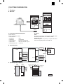
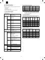
[1] SYSTEM CONFIGURATION
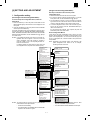
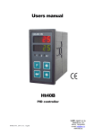
1. Hardware
A. Main Unit
Print Server Card
AR-NC3D
(10Base-T / 100Base-TX)
Printer Expansion kit
AR-PB2A
Expansion Memory
AR-SM1
CD-ROM
Scanner Expansion Kit
AR-NS1
SDRAM
CD-ROM
(1) Print Controller Hardware and Options
(2) Options
Controller Hardware
Hardware configuration is as follows:
• ProcessorR 4700
• Base Memory
16 MB
• Flash Memory
1 slot with 8 MB
• Memory Expansion
2 Standard 72 pin SIMM slots
• Parallel Interface
1 IEEE 1284 compatible Type B
• Network Expansion Slot 1 Internal slot
DRAM
The system can optionally be configured with up to 64-MB optional
DRAM Using industry standard, 16 or 32 Mb72 pin SIMMs.
Network Server Card
AR-PB2 Printing system can optionally be configured with Network
Server Card of supporting 10Base-T and 100Base-TX.
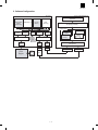
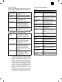
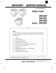
B. System Elements
AR-PB2A printer
Windows PC
Print data/
Setting data
Copier
Printer Controller
Own
Printer
Driver
P1284
Bitmap data
Ethernet
ICU
SCSI I/F
command/status
DPO I/F
eRDH
NIC
(DPI)
Print data/
Setting data
Scan data
Bitmap data
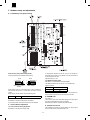
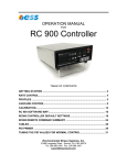
C. Input/Output Device Options
3Tray
Finisher
2Tray
Finisher
STD Output
(1Tray) or
(2Tray)
Bypass Tray
(BT)
ADU
Tray1
2Tray
Output
Tray2
Tray3
Tray4
Tray5
1–1
(Only Japan
Domestic)
LCC
Option
AR-PB2A
D. Accessory and Options
Part name
Accessories
Option
Model
Q’ty
SCSI cable
1
Wire saddle
1
Band
1
Printer box installing screw
5
Printer control PWB
1
Printer driver
1
Printer Driver (including PPD File)
Screen Font
1
Resident-FontData Install Utility
1
Printer Administration Utility ver.2.x
1
NWsetup
1
Printer Status Monitor ver.2.0
1
Integrated Installer
1
Makedisk Utility
1
Installation manual
1
Operation Manual
1
Label
1
SIMM memory
16MB
With frame
Only for Sweden and Norway
ED0 type/Without parity/70ns or above
The copier ICU PWB requires the total
memory of 16MB(20MB) or more.
The printer control PWB has two expansion
slots to which 16MB or 32MB memory can
be additionally installed. (16MB onboard)
32MB
Network card
Separate purchase
(User purchase)
Note
AR-NC3D
1
Printer (parallel) cable
10Base-T / 100Base-TX
Necessary when the copier is used as a
stand-alone machine.
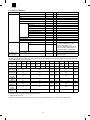
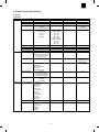
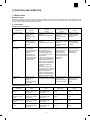
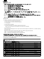
E. List of the Applicable Models for the AR-PB2A Printer Expansion Kit
The details of the specifications, features, and options of the printer may vary with the printer models. Some features described in this manual may
not be available depending on the printer drivers.
Model Name
AR-280
Hard disk
drive
Yes
Capacity
2GB *
AR-285
Yes
2
2GB *
2
AR-335
AR-250
AR-281
AR-286
AR-336
AR-405
AR-505
AR-287
AR-337
AR-407
AR-507
Yes
No *
1
Yes
Yes
Yes
Yes
Yes
Yes
Yes
Yes
Yes
1GB
2GB
2GB
2GB
2GB
2GB
4.3GB
4.3GB
4.3GB
4.3GB
2GB *
2
Reverse
order printing
Yes
Yes
Yes
No
Yes
No
Photo
enhancement
No
No
No
Yes
Yes
Yes
Toner save/
smoothing
No
Yes
Yes
Yes
Yes
Yes
Confidential
print
No
No
No
No
Yes
Yes
Tandem print
No
No
No
No
Status/alert
by E-mail
No
No
No
No
Yes
Yes
Account
control
No
No
No
No
Yes
Yes
Network
scanner *3
No
No
No
No
Yes
Yes
No
Yes
*1 Optional
*2 Some units of the models may come with a 1 GB hard disk drive.
*3 Optional AR-NS1 is needed.
AR-PB1 A and AR-PB2 A are available for following models however, the available functions can vary with the copier models installed.
1–2
Yes
AR-PB2A
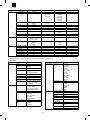
2. Software Configuration
Firmware
Win3.1x/Win95/WinNT4.0
Application
ESC/P Super
ESC/P
(Japan only)
PostScript L2
PCL5e
(SPDL)
PCL6
(EX only)
GDI (Graphic Module)
Printer Driver
Others
PostScript
Front Panel
Control
Print Queue
Manager
Engine I/F Manager
Font
Manager
Roman
Font
Kanji
PJL
AUTO
Switching
PCL
(SPDL)
PostScript
PPD
PCL6
(EX only)
Host I/O Manager
(Japan only)
(Japan only)
SCSI-2 I/F
Driver
Print
Engine
eRDH
DPO
Driver
1284
Driver
DPO
Port
1284
Port
Print Spooler
1284 Port
NIC
1–3
Ethernet Port
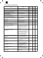
AR-PB2A
B. Printer Driver Compatibility
[2] SPECIFICATION
NO.
New function provided by combination use with AR-287/337/407/507
• Confidential Print
• Tandem Print
• E-mail Status/E-mail Alerts
• Potential to enhance the Network Document Scanner
A. Specification
Support OS
(Printer
Driver)
IBM PC/AT (Include compatible machine)
Custom PS
3
Windows PCL5e
4
Windows PCL6
✕
✕
✕
✕
✕
✕
✕
✕
✕
✕
Language Localization
The description of the driver including the help file, front panel menu
and print text must be provided in various languages as follows:
Windows 3.1/WfW3.11
Windows 95/98
Windows NT 4.0
Language
Custom SPDL
N/A
Custom PCL5e
Windows 3.1/WfW3.11
Windows NT4.0
Windows 2000
Custom PCL6
Windows 95/98
Windows NT4.0
Windows 2000
Windows PPD
Windows 95/98
MacOS9
❍
❍
❍
❍
❍
❍
German
❍
❍
❍
❍
❍
❍
French
❍
❍
❍
❍
❍
❍
Italian
❍
❍
❍
❍
❍
❍
Spanish
❍
❍
❍
❍
❍
❍
Dutch
❍
❍
❍
❍
❍
❍
Swedish
❍
❍
❍
❍
❍
❍
❍
❍
❍
❍
Language
PostScript Level 2 emulation
10/100Base-T (AR-NC3D)
Support OS
UNIX
Windows 3.1/95/98
Windows NT3.51/4.0
Windows 2000
Novell NetWare 3.x / 4.x / NetWare 5
Macintosh System 7.x / MacOS 7.5.x /
MacOS 8.x / MacOS 9
Base Protocols
IPX/SPX for Novell
TCP/IP for Windows and UNIX
EtherTalk for Macintosh
Printing
Protocols
PSERVER for NDS or bindery environment
with Novell
LPR / LPD
EtherTalk
FTP
TCP Raw Socket (Direct Dump)
CPU
R4700 (64bit RISC / 150MHz)
Standard
EDO RAM 16 MB
Max
80 MB
Slot
2 Slots
EDO type 72pin standard SIMM 16MB or
32MB
For PS
80 fonts (Same 80 fonts as PCL)
For PCL5e,
PCL6, SPDL
80 fonts (Same 80 fonts as PS)
Printer
Front
Panel
Demo
Pages
English
PCL5e emulation
PCL6 emulation
Interface
Windows
SPDL
Windows Macintosh
PS2
driver
PPD
PPD
driver
❍
"Localization" includes changing default paper selection etc. to meet
the needs of each market.
The following is language-application matrix.
Windows 2000
Macintosh PPD MacOS 7.6 – 8.6
PDL
PCL5e PCL6
driver driver
Japanese
Windows NT 4.0
Resident
Fonts
Windows PPD
WIN NT
Power Macintosh, iMac
Windows 95/98
Memory
Windows PS
2
WIN 95/
WIN 98
Macintosh (680 x 0)
Windows 2000
Network 1
1
WIN 3.1
NOTE: Users of Windows will obtain maximum functionality and better output quality by installing the Windows PostScript
Printer driver. Alternatively, the Windows PCL5e driver will
provide the best print speed.
1. General Specification
Platform *1
PRINTER DRIVER
Line Printer
2–1
Printer
Printer Status
Administration
Monitor
Utility
NW Setup
Integrated
Installer
English
❍
❍
❍
❍
German
❍
❍
❍
❍
French
❍
❍
❍
❍
Italian
❍
❍
❍
❍
Spanish
❍
❍
❍
❍
Dutch
❍
❍
❍
❍
Swedish
❍
❍
❍
❍
Japanese
❍
❍
❍
❍
AR-PB2A
2. Printing Function Specification
A. Outline
(1) Windows
General
Function
Copies
Orientation
Reverse Order
Duplex
Booklet
Paper Input
Binding Edge
N-up
N-up Order
N-up Border
Paper Size
Custom Paper Size
PCL5e custom driver
1-999
Portrait Landscape
Yes / No
1-Sided
2-Sided
(Left /Top/Right Binding)
Invoice on Letter
Letter on Ledger
A5 on A4
A4 on A3
B5 on B4
Left / Top / Right
N/A
N/A
N/A
A3 / B4 / A4 / B5 / A5 / A6 /
Japanese Postcard / Ledger /
Legal / Foolscap / Letter /
Executive / Invoice
1 size
PCL6 custom driver
←
←
←
←
PS custom driver
←
←
←
←
Invoice on Letter
Letter on Ledger
A5 on A4
A4 on A3
B5 on B4
Letter on Letter
Ledger on Ledger
A4 on A4
A3 on A3
B4 on B4
←
2/4/6/8/9/16
Z
Yes / No
←
←
PPD file *1
←
←
←
1-Sided
2-Sided
(Long/Short Binding)
N/A
←
←
←
←
←
Long / Short
2/4 *2
←
Always Yes
←
←
1 size
←
←
3 sizes (0 sizes for
WindowsNT and
Windows2000)
←
←
←
N/A
←
←
←
←
←
←
←
←
←
←
←
Source Selection
Automatic
Bypass-Tray
Bypass-Tray(Manu.)
Tray 1/2/3/4
Large Capacity Tray
Different 1st Page
Yes / No
It is possible to select
whether print back-side of
first paper with duplex
Transparency Inserts
No
Yes (Blank)
Yes (Printed)
Paper Output Output Tray Selection 1 Exit Tray
Not Selectable
2 Exit Trays
Top Tray
Second Tray
2 Tray Finisher
Top Tray
Offset Tray
3 Tray Finisher
Top Tray
Second Tray
Offset Tray
Face-up/down
Yes / No
Staple
2 Tray Finisher
Yes / No
3 Tray Finisher
No staple
1 staple
2 staples
Yes
2–2
AR-PB2A
Graphic
Function
Resolution Setting
Halftone Setting
Graphics Mode
Smoothing
Toner save
Photo Enhancement
Negative Image
Mirror Image
Font
Zoom
Fit to Page
Resident Font
Download Font
Others
Configuration Setting
Watermark
Form Overlay
Confidential Print
Print Accounting
Tandem Print
Job End Notification
PCL5e custom driver
600dpi
N/A
PCL6 custom driver
←
Photo image
Line image
Scan image
Raster
HP-GL2
Yes / No
Yes / No
N/A
N/A
N/A
Raster
Vector
←
←
N/A
←
←
N/A
Yes
80 fonts
Category 1, 3 and 4
In font chapter
Bitmap
TrueType
Graphics
Yes
Yes
Yes
Yes
Yes
Yes
Yes
←
←
←
←
←
←
←
←
←
←
←
PS custom driver
←
Screen Frequency
8.0 to 360.0
in 0.1 steps
Screen angle
0.0 to 360.0
in 0.1 steps
N/A
PPD file *1
←
←
←
←
Yes / No
Yes / No
Horizontal
Vertical
N/A
←
←
←
←
N/A
←
Horizontal
Bitmap
Type1
TrueType
←
←
N/A
←
←
←
←
←
←
25-400%
N/A
←
←
N/A
←
N/A
N/A
←
N/A
*1...This file is required for printing on the Cougar using Adobe PS driver (V4.0)
*2...Windows NT does not support N-up printing. All Windows but NT support 2-up and 4-up only.
(2) Macintosh
General
Paper Input
Function
Copies
Orientation
Macintosh PPD file
1-999
Portrait
Landscape
Reverse Order
Yes / No
Duplex
1-Sided
2-Sided
(Left /Top/ Right Binding)
Booklet
N/A
Binding Edge
Long / Short
N-up
2/4/6/9/16
N-up Order
Z / reversed Z
N-up Border
None / Single Hairline / Single
Thinline / Double Hairline /
Double Thinline
Paper Size
A3 / B4 / A4 / B5 / A5 / A6 /
Japanese Postcard /
Ledger / Legal / Foolscap /
Letter / Executive / Invoice
Custom Paper Size N/A
Source Selection
Automatic
Bypass-Tray
Bypass-Tray(Manu.)
Tray 1/2/3/4
Large Capacity Tray
Different 1st Page
Yes / No
Transparency
No
Inserts
Yes (Blank)
Yes (Printed)
Function
Paper Output Output Tray
Selection
Face-up/down
Staple
Graphic
Resolution Setting
Halftone Setting
Graphics Mode
Smoothing
Toner save
Photo
Enhancement
Negative Image
Mirror Image
Zoom
Fit to Page
2–3
Macintosh PPD file
1 Exit Tray
Not Selectable
2 Exit Trays
Top Tray
Second Tray
2 Tray Finisher
Top Tray
Offset Tray
3 Tray Finisher
Top Tray
Second Tray
Offset Tray
Yes / No
2 Tray Finisher
Yes / No
3 Tray Finisher
No staple
1 staple
2 staples
600dpi
N/A
N/A
Yes / No
Yes / No
N/A
Yes / No
Horizontal
Vertical
25-400%
N/A
AR-PB2A
Function
Resident Font
Font
Download Font
Configuration
Setting
Watermark
Form Overlay
Confidential Print
Others
RAM:
DRAM
SIMM
Host I/O:
P1284
Macintosh PPD file
35 fonts
Category 1
In font chapter
N/A
Yes
External I/O
Engine I/F:
SCSI-2
N/A
N/A
Yes
(PIN selection)
Print Accounting
Yes
Tandem Print
Yes
Job End Notification N/A
All functionality is supported.
AR-405/336/286/
281/250
Printing Settings tab and Resources
tab are not displayed.
AR-335/285/280
Printing Settings tab and Resources
tab are not displayed. Some
information display may be limited.
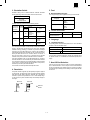
(1) Connectivity
a. Direct Connection
The Cougar print system supports IEEE 1284 (parallel)-connection.
Direct Connection Type
Properties
•
•
•
IEEE 1284 Compliant
c. Emulation
Automatic (PCL5e ↔ PS ↔ PCL6)
PCL (fixed)
PostScript (fixed)
SPDL (fixed)
Emulation switching is performed in the following manner.
Compatible
Connector: 1 (Type B)
b. Internal Network Connection
The Cougar print system supports an internal network connection.
Installing either of the following print server cards allows the system to
connect to the network.
Model Name
PJL Command
for Specifying
an Emulation
Network Type
AR-NC3D
10Base-T / 100Base-TX
Yes
(2) Printer Controller
ROM:
Flash ROM
EEPROM
Specified
Emulation
No
c. Network Print Channel
The Cougar printing system supports the following network print
channels.
• PSERVER for NetWare Environment
• LPR / LPD
• EtherTalk (AppleTalk)
• FTP
• TCP Raw Socket
a. Hardware
CPU:
Peripheral ASIC:
1ch: Asynchronous and Synchronous/16bits
bus DMA
PJL(PJL is used in emulations other than
PCL5e.)
Emulation:
PCL5e
PostScript
Emulation Switching AUTO, PS, PCL
Resident Fonts:
PCL5e (SPDL)
80 Fonts (HP8000 Typeface compatible)
Lineprinter
PostScript
Roman
80 Fonts (Adobe PS Printer Typeface compatible)
PCL6
80 Fonts
Host I/O:
P1284
Compatible, Nibble for PnP
External I/O
DPO Type2 for DPI (HBM) NIC
I/O Switching
AUTO, P1284, NIC
Engine I/F:
SCSI-2
Asynchronous and Synchronous /DMA transfer
B. Details
IEEE 1284
1ch: B connector (CL-CD1283)
16bits bus DMA
1ch: DPO Type2 for DPI (HBM) NIC (optional)
b. Firmware
Job Control:
NOTE: When the AR-PB2A is installed in AR-505/507/407/337/287,
the Printer Administration Utility is fully functional; however, if
the AR-PB2A is installed in other models, its functionality is
limited as follows:
AR-505/507/407/
337/287
16 MB (EDO)
2 slots: 16/32 MB (Max. 32x2 + 16 = 80 MB)
Emulation Setting
Automatic
Fixed
Automatic
Sensing
OK
Uses the
Uses a default
emulation
emulation.
automatically
selected.
NG
Uses PCL
Yes
Uses the emulation
specified.
No
Uses PCL
Uses the
emulation
specified.
Uses a default
emulation.
In the automatic emulation sensing mode, for print data without the
PJL command, the emulation is automatically switched either to PostScript, PCL5e based on data sensed. In other words, automatic
emulation sensing (switching) is available only between PostScript
and PCL5e. For print data with the PJL command, the emulation is
automatically switched to the specified one without sensing the data.
When print data without the PJL command fails to be sensed, or
when the print data is given the PJL command but the specified
emulation is not present, the data is handled in the PCL emulation.
In the fixed emulation mode, for print data without the PJL command,
the fixed emulation is used to handle the print data. Print data with the
PJL command is switched to the specified emulation. When print data
is given the PJL command but the specified emulation is not present,
the data is processed by the default emulation.
The PJL Enter command specifies PostScript and PCL5e.
R4700 150MHz(64Bits RISC)
Galileo-Technology GT-64010A
DRAM Controller
DMA-4 ch (SCSI, P1284, IDE, Option I/F)
8 MB
(Boot (Sim)&Main Program/ Roman Font)*1
8 KB
2–4
AR-PB2A
(3) Engine Spec.
Maximum Paper Size
Print Resolution
Smoothing
Toner Save Print
Photo Enhancement
Engine Speed
Print Speed
Input Paper Trays
Support Paper Sizes
Output Devices
Electric Collation
Duplex Printing
Paper size
Invoice
Executive
Foolscap
Japanese Postcard
A3, 11" x 17"
600 x 600 dpi
Yes
Yes
Yes
28ppm: AR-287
33ppm: AR-337
40ppm: AR-407
50ppm: AR-507
(8.5" x 11 continuous printing of same page)
28ppm: AR-287
33ppm: AR-337
40ppm: AR-407
50ppm: AR-507
(Tested by continuous printing of
4Kcharacter/Page text data)
Standard: Tray 1 / Tray 2 / Bypass Tray
Option: Tray 3 / Tray 4 / LCC
A6, A5, A4, A3, B5, B4, Japanese Postcard
(148 x 100mm), 5.5" x 8.5"(Invoice), 7.25" x
10.5"(Executive), 8.5" x 11"(Letter), 8.5" x
13"(Foolscap), 8.5" x 14"(Legal), 11" x
17"(Ledger)
Custom (Max;297 × 432_Min;100 × 148)
1 Exit Tray
2 Exit Trays (for AR-287 / AR-337 / AR-407)
2-Tray Finisher (for AR-287 / AR-337 /
AR-407)
Face-up 3-Tray Finisher (for AR-287 /
AR-337 / AR-407)
Face-down 3-Tray Finisher (for AR-507)
Support By E-RDH
(Software collation will not be supported.)
Yes with duplex option
X
4992
4224
4992
2240
Y
3168
6176
7680
3392
(dots in 600 dpi)
(6) Font
a. Resident Font
Resident Fonts
Emulation
PCL5e
Roman
PCL6
PostScript
Roman
Resident Font
80 Fonts (Bitstream)
1 Font-Bitmap (Bitstream)
80 Fonts (Bitstream)
1) PCL5e Roman fonts
Font format:
(80 fonts), Bitmap(1 font)
Font data size:
Approx. 1.9MB
Font supplier:
Bitstream
Font name
Dutch™ 801 SWC
Dutch 801 Italic SWC
Dutch 801 Bold SWC
Dutch 801 Bold Italic SWC
Swiss™ 742 SWC
Swiss 742 Italic SWC
Swiss 742 Bold SWC
Swiss 742 Bold Italic SWC
Swiss 742 Condensed SWC
Swiss 742 Condensed Italic SWC
Swiss 742 Condensed Bold SWC
Swiss 742 Condensed Bold Italic SWC
Incised 901 SWC
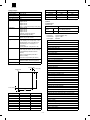
(5) Print Area
Incised 901 Italic SWC
Incised 901 Bold SWC
2.7mm (7/64")
Zapf Humanist 601 SWC
2.7mm (7/64")
Printable area
Zapf Humanist 601 Italic SWC
Zapf Humanist 601 Bold SWC
Zapf Humanist 601 Bold Italic SWC
Aldine 430 Original Garamond SWC
Aldine 430 Original Garamond Italic SWC
Aldine 430 Original Garamond Bold SWC
Y
Aldine 430 Original Garamond Bold Italic SWC
Fixed Pitch 810 Courier Roman SWC
Fixed Pitch 810 Courier Italic SWC
Fixed Pitch 810 Courier Bold SWC
2.7mm (7/64")
Fixed Pitch 810 Courier Bold Italic SWC
X
2.7mm (7/64")
Paper size
A3
B4
A4
B5
A5
A6
Ledger
Letter
Legal
X
6912
5952
6912
5952
4864
2368
6464
6464
4992
Fixed Pitch 850 Letter Gothic 12 pitch/text SWC
Fixed Pitch 850 Letter Gothic Bold 12 pitch/text SWC
Fixed Pitch 850 Letter Gothic Bold Italic 12 pitch/text SWC
Y
9824
8480
4864
4192
3392
3392
10080
4992
8288
Flareserif 821 SWC
Flareserif 821 Extra Bold SWC
Clarendon 701 Clarendon Condensed SWC
Ribbon 131 SWC
Audrey Two SWC
Swiss 721 SWM *1
Swiss 721 Oblique SWM *1
Swiss 721 Bold SWM *1
Swiss 721 Bold Oblique SWM *1
2–5
AR-PB2A
Dutch 801 SWM *1
Font name
ITC Bookman® Demi
ITC Bookman Demi Italic
ITC Bookman Light
ITC Bookman Light Italic
810 Courier®
810 Courier Bold
810 Courier Bold Italic
810 Courier Italic
Swiss 721 Normal
Swiss 721 Bold
Swiss 721 Bold Oblique
Swiss 721 Oblique
Swiss 721 Narrow
Swiss 721 Narrow Bold
Swiss 721 Narrow Bold Oblique
Swiss 721 Narrow Oblique
Century Schoolbook Bold
Century Schoolbook Bold Italic
Century Schoolbook Italic
Century Schoolbook Roman
Zapf Calligraphic 801
Zapf Calligraphic 801 Bold
Zapf Calligraphic 801 Bold Italic
Zapf Calligraphic 801 Italic
Symbol Set
Dutch( 801 Bold
Dutch 801 Bold Italic
Dutch 801 Italic
Dutch 801 Normal
ITC Zapf Chancery® Medium Italic
ITC Zapf Dingbats®
Dutch 801 Italic SWM *1
Dutch 801 Bold SWM *1
Dutch 801 Bold Italic SWM *1
Symbol SWA
Wingbats SWM
Line Printer *2
Dutch 801™ SWA
Dutch 801 Italic SWA
Dutch 801 Bold SWA
Dutch 801 Bold Italic SWA
Swiss™ 721 SWA
Swiss 721 Oblique SWA
Swiss 721 Bold SWA
Swiss 721 Bold Oblique SWA
Fixed Pitch 810 Courier® SWA
Fixed Pitch 810 Courier Italic SWA
Fixed Pitch 810 Courier Bold SWA
Fixed Pitch 810 Courier Bold Italic SWA
Symbol SWA (PS)
Zapf Calligraphic 801 SWA
Zapf Calligraphic 801 Italic SWA
Zapf Calligraphic 801 Bold SWA
Zapf Calligraphic 801 Bold Italic SWA
Revival 711 ITC Bookman® Light SWA
Revival 711 ITC Bookman Italic SWA
Revival 711 ITC Bookman Demi SWA
Revival 711 ITC Bookman Demi Italic SWA
Swiss 721 Narrow SWA
Swiss 721 Narrow Oblique SWA
Swiss 721 Narrow Bold SWA
b. Download Fonts
Data formats of download fonts in each emulation are in the table
below.
Swiss 721 Narrow Bold Oblique SWA
Century 702 Century Schoolbook SWA
Century 702 Century Schoolbook Italic SWA
Century 702 Century Schoolbook Bold SWA
Emulation
Century 702 Century Schoolbook Bold Italic SWA
Roman
Kanji
N/A
PostScript
Roman
Bitmap
Type 1
Type 42
Kanji
N/A
Geometric 711 ITC Avant Garde Gothic® Book SWA
Geometric 711 ITC Avant Garde Gothic Book Oblique SWA
Geometric 711 ITC Avant Garde Gothic Demi SWA
Geometric 711 ITC Avant Garde Gothic Demi Oblique SWA
Chancery 801 ITC Zapf Chancery® Medium Italic SWA
ITC Zapf Dingbats® SWA
All above resident fonts in the column are licensed from Bitstream
Inc. Dutch and Swiss are trademarks of Bitstream Inc. All other
trademarks and copyrights are the property of their respective
owners.
*1: These fonts cannot be used with the PS driver.
*2: For Line Printer in the above table, display font is not supplied.
2) PS2 Roman fonts
Number of fonts: 80
Font format:
(All of the 80 fonts)
Font data size:
Approx. 0.9MB
Font supplier:
Bitstream
Download Font
PCL5e
Bitmap
TrueType
Intellifont
(7) Interface Specification
The printing system supports IEEE 1284 compliant connections
Properties
IEEE 1284
• IEEE 1284 Compliant
• Compatible
• Connector: 1 (Type B)
(8) Network Specification
Interface
Support OS
DPI_NIC 10Base-T
NetWare,
100Base-TX Windows NT
Font name
ITC Avant Garde Gothic® Book
ITC Avant Garde Gothic Book Oblique
ITC Avant Garde Gothic
ITC Avant Garde Gothic Demi Oblique
2–6
Support
Protocol
Area
IPX/SPX,
TCP/IP,
EtherTalk,
Peer to Peer
(IPX/SPX)
JPN, North
America
(USA/
CANADA),
Europe, EX
AR-PB2A
[3] SETUP
1. Parts list
Before installing the printer kit, check that all the following items are prepared.
Be careful that the necessary parts depend on the environment of the copier (model and unit installation).
Accessories
Option
Part name
SCSI cable
Wire saddle
Band
Printer box installing screw
Printer control PWB
Printer driver
Printer Driver (including PPD File)
Screen Font
Resident-FontData Install Utility
Printer Administration Utility ver.2.x
NWsetup
Printer Status Monitor ver.2.0
Integrated Installer
Makedisk Utility
Installation manual
Operation Manual
Label
Expansion board
SIMM memory
Separate purchase
(User purchase)
Model
Q’ty
1
1
1
5
1
1
1
1
1
1
1
1
1
1
1
1
1
AR-EB1
16MB
32MB
Network card
Printer (parallel) cable
AR-NC3D
1
Note
With frame
Only for Sweden and Norway
The expansion board is necessary to
install the printer kit to the AR-S280.
ED0 type/Without parity/70ns or above
The copier ICU PWB requires the total
memory of 16MB(20MB) or more.
The printer control PWB has two
expansion slots to which 16MB or 32MB
memory can be additionally installed.
(16MB onboard)
10Base-T / 100Base-TX
Necessary when the copier is used as a
stand-alone machine.
2. Preliminary work
If the version of the three kinds of flash memory installed to the copier
is older than the following, upgrade is required.
Check version number, and perform the upgrade if necessary. (For
the procedure, refer to the Technical Report.)
Connector
Screw
3. Hardware setup
A. Common work
If the rear cabinet is a box type, remove the connector cover in
advance.
Remove the five securing screws which hold the rear cover of
main copier unit, then remove the rear cover.
Next, loosen the upper central one of four securing screws which
hold the rear lower cover, then remove the rest three screws, and
then remove the rear lower cover.
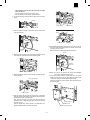
(1) Printer unit installation
1) Turn "OFF" the main switch located on the left-hand side on the
main copier unit.
Next, unplug the power plug of the main copier unit from the
outlet.
Main switch
• If the rear cabinet is a box type:
"OFF"
Rear
cover
Rear cover
Securing
screw
2) Removing the rear cover of the main copier unit.
If equipped with the RADF/ADF/SPF, loosen the securing screws
which the hold the RADF/ADF/SPF connector and remove the
connector from the main copier unit.
Loosen
Rear
lower cover
Securing screws
3–1
Securing
screw
Connector
cover
Loosen
Rear
lower cover
Securing screws
AR-PB2A
•
The installation work after this step varies with the shape
of the rear cabinet.
• If the rear cabinet is a box type, proceed to step 9.
• If the rear cabinet is not a box type, proceed to step 3.
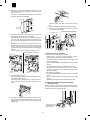
3) Cut out the central one of three notches of upper rear cover with a
nipper.
Binding
band
Ribs
Notches
Securing screws
Shield line guide
A notch
4) Remove the three securing screws which hold the flywheel and
remove the flywheel.
Cut away the surplus
Binding
band
Flywheel
Printer relay cable
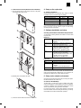
8) Reinstall the flywheel (which was removed in the step 4) onto the
main drive shaft while slipping inside the exterior. Use the three
securing screws to secure it.
Make sure the arrow mark on flywheel faces toward you.
Securing
screw
Caution
5) Remove the two securing screws which hold the shield line guide
to the main drive frame and remove the shield line guide.
Flywheel
Shield line
guide
Engraved
arrow mark
Securing
screw
Securing screws
<Caution> Do not turn the flywheel with hands after installation
since it may cause damage to the gears.
9) Connect the power connector of printer box unit to the power
supply port on the main copier unit, then attach the printer box unit
on the holes of F/P box mounting plate using the hooks.
Using the 5 printer box securing screws, attach the printer box to
the mounting plate.
6) Plug the printer relay cable connector into the most right hand port
on the ICU board.
Port on the ICU board
Hook
Printer relay cable
7) Place the printer relay cable into the central notch of shield line
guide (the location with a letter P) and attach it temporarily with a
binding band as shown in the illustration.
Next, insert the two ribs on the main drive frame through the
positioning holes of shield line guide, then use the two securing
screws to secure it.
Place the printer relay cable as shown in the illustration, then
tighten the binding band and cut away the excess.
Power connector
Printer box unit
Printer box securing screw
3–2
AR-PB2A
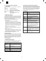
10) Remove the securing screws holding the P side OP cover in the
rear lower cover which was removed in the step 2, then remove
the P side OP cover.
Next, paste an attached label at the position only for Sweden
and Norway as shown in the illustration.
Screw
P side OP cover
Connector
1. Connect the printer relay cable to the connector of printer
box.
2. Attach the supplied wire saddles to the printer relay cable.
3. Insert and fix the wire saddle at the position of rear lower
cover as shown in the illustration.
Label
Securing
screws
Wire saddle (1 pc.)
11) Hook the rear lower cover on the securing screw ➃ which was
loosened in the step 2 as shown in the illustration.
Next, tighten the securing screws ➀, ➁ and ➂ temporarily, which
were removed in the step 2 and tighten the securing screw ➃
which was loosened, then tighten the securing screws ➄, ➅ and
➆.
Reinstall the rear cover which was removed in the step 2 to the
original position by putting it onto the securing screws ➀, ➁ and
➂ which temporarily secure the rear cover, then tighten the
securing screws ➀, ➁ and ➂ after tightening the securing screws
➇ and ➈.
If the rear cabinet is a box type, attach the connector cover.
Wire saddles (2 pcs.)
Printer relay cable
Printer relay cable
• If the rear cabinet is a box type:
Securing screw
Loosened
screw
Rear lower
cover
Securing
screws
(2) Expansion memory installation
Securing screw
a. Memory expansion in the printer control PWB
Normally there is no need for memory expansion. However,
memory expansion will increase the printer performance.
When printing graphics or complex data, memory expansion will
increase printing speed.
Memory of 16MB or 32MB can be installed to the two slots. (16MB
onboard)
Different capacity of memory can be installed to the two slots.
The total memory after expansion may be 32, 48, 64, or 80MB.
After the above procedure, select VM Option menu and set the
total memory capacity.
b. ICU PWB memory expansion
The copier ICU PWB requires total memory capacity of 16 (20)MB
or more.
Memory of 16MB or 32MB can be installed to the two slots. (4MB
onboard)
Different capacity of memory can be installed to the two slots.
Rear
cover
Rear cover
Connector
cover
Loosened
screw
Securing
screws
• If the rear cabinet is a box type:
Rear lower
cover
12) If the rear cabinet is a box type:
Insert the printer relay cable connector to the rightmost connector of the ICU PWB to connect it.
If an option has been already connected to the right SCSI connector of the copier, however, connect the cable to the left connector.
B. Stand-alone environment (Printer (parallel)
cable connection)
Plug the connector of the Centronics cable (sold separately) into the
Centronics port on the printer box base.Plug the other connector into
the laser printer port on a personal computer.
13) If the copier is equipped with an automatic document feeder,
connect the connector that has been removed in step 2 to its
original position of the copier and secure the connector with the
attached screw.
Connector going to the
laser printer port on the
personal computer
3–3
Centronics cable
(sold separately)
AR-PB2A
C. Network environment (Network card installation)
4. Setup on the copier side
1) Insert the network card into the network card slot on the printer
control PWB. and fix it with screws.
A. Setup by simulation
Setup the following items. For parallel I/F, setup, if there is no trouble
in operations, there is no need to change any settings.
Simulation No.
Set value
System configuration setup
Content
26-44
1
Print counter count mode setup
26-05
Parallel I/F timing adjustment
67-03
Parallel I/F select IN signal timing
67-11
B. Setup by key operator program
Refer to the section of the key operator program and make setting
according to the user environment.
5. Software installation and setup
Checking the Hardware and Software Requirements
You will need the following hardware and software in order to install
the printer driver.
(Windows)
Computer Type
•
Operating System
•
CPU
•
•
RAM
•
•
•
•
IBM PC/AT or compatible computer
equipped with a bi-directional parallel
interface
Windows 3.1x, Windows 95, Windows 98,
Windows 2000, Windows NT 4.0
Windows 3.1/Windows 95: 486SX or better
Windows 98: 486DX/66 MHz or better
(Pentium or better is recommended.)
Windows NT4.0: 486/25MHz or better
Windows 3.1/Windows 95: 8 MB or more
(12 MB or more is recommended.)
Windows 98/Windows 2000: 16 MB or more
(32 MB or more is recommended.)
Windows NT 4.0: 16 MB or more
(Macintosh)
Mac OS 7.6 to 9.0
RAM
•
•
•
•
•
12 MB or more for MC 68040 machine
Printer driver
Operating system
CPU
MC 68040 or PowerPC microprocessor
16 MB or more for PowerPC microprocessor
machine
LaserWriter 8 version 8.4.1 or later
To use the printer with a Macintosh computer, an optional network
interface card (Print Server Card) is needed. Also the Macintosh computer must be equipped with an Ethernet port. If your computer is not
equipped with an Ethernet port, install an Ethernet interface.
6. Setup under network environment
2) Install the printer control PWB to the copier.
Check the user environment and make setup according to the Operation Manual attached to the network card.
A. Outline of the NW Setup
The NW Setup is a setup tool for using a SHARP printer with a
network card installed in a Novell NetWare environment. Registration
of printers to a NetWare server and parameter settings for a network
card can be performed by using a procedure with wizards.
For using the NW Setup, a Novell Client supplied by Novell must
have been installed. Also before starting the NW Setup, you must log
in the NetWare server with the ’Administrator’ privileges.
3) Connect the network cable to the network card connector.
3–4
AR-PB2A
B. Checking the Hardware and Software
Requirements
B. E-mail Setup and Network Scanning Setup
In the "Status/Alert by E-mail" function, SMTP (Simple Mail Transport
Protocol) protocol is used to send the e-mails. This section describes
how to set up the basic status of the e-mail sending including the
definition of the file names for the image data to be attached and so
on. Such settings must be effected by the system administrator who
has the special network related backgrounds.
To use the NW Setup, the following hardware and software are
needed.
NetWare server:
NetWare client:
Client PC operating
system:
Printer:
IntranetWare (NetWare 4.x)
Novell Client 4.5 for Windows NT
Novell Client v3.0 for Windows 95/98/2000
Windows 95, Windows 98, Windows 2000,
Windows NT 4.0
SHARP printer with a Print Server Card
(AR-NC3D) installed
(1) E-mail Setup
Item
7. Web Page Setting
This copier/printer is equipped with web page features that allow
some network-related functions such as the network scanner function
and the Status & Alert by E-mail function to be set and used with a
web browser. (An optional Network Scanner Expansion Kit AR-NS1 is
required to use the network scanner function.)
The web page feature includes the following three types.
1. Password Setting
Setting up the administrator’s and user’s passwords.
The administrator of this software can set the passwords (for administrator and user) to authorize the access to the E-mail Setup
Web page for the security of the settings on the page. If such a
security measure is not required, the Password Setting procedure
can be skipped. This will leave Web access settings open to all
users.
2. E-mail Setup and Network Scanning Setup
Configuration of the network scanning system and status/alert by
E-mail.
3. Scanning Destination Setup
Setting the default scanning parameters on the device to send the
scanned image or data as Destinations. (An optional Network
Scanner Expansion Kit AR-NS1 is required for this setup.)
First, assign an IP address to the copier/printer.
A. Password Setting
The administrator should exclusively do the setting of the password of
two levels: User and Admin when setting up network scanning system
security. A User password is required to create, change, and delete
destinations. An Admin Password lets you access to the same functions as the User password but is also required to set system configuration settings such as:
• Password Setup page
• Setup Status & Alerts by E-mail pages
• E-mail/Network Scanning Setup page
When you first install your network scanning system, both password
functions are disabled. To set a User and/or Admin password.
Name
Definition
Enable Password
Protection of This
Web Site
To enable password protection, check the
box and click the ‘Submit’ button. To disable
it, clear the check mark in the box and click
the ‘Submit’ button.
User Access in
Destination List
Enter a User password within 10 characters.
Confirm Password
Enter the User password again to confirm it.
Admin Control for
E-mail/Scanning
Enter an Admin password within 10
characters.
Confirm Password
Enter the Admin password again to confirm it.
3–5
Description
Name
Enter a unique name for the machine within 50
characters.
Machine Code
This is not used. This field can be used to input
some machine related information. Some dealers
may use this field to identify the machine.
Machine
Location
Enter a unique entry for the machine location
within 100 characters.
Primary
E-mail Server
Enter an IP address for the primary e-mail server
or a host name.
Secondary
E-mail Server
Enter an IP address for the secondary e-mail
server or a host name. No need to enter if
secondary e-mail server is not set up.
E-mail Time
Out
Enter a time out period, from 0 to 60 seconds,
that the system will wait for as it attempts to
connect to the primary server. The default is 20
seconds. If no connection is made, the system
will then look for the secondary server if it has
been set up. If not, the system will stop
attempting to connect.
Reply Address
Enter an e-mail address to which the machine
returns an unsuccessful delivery message when
the distribution has failed. Only 1 e-mail address
can be entered.
Time Zone
Select the time zone of the place to use this
Network Scanning System. A specific time zone
is set after the selection.
AR-PB2A
(Using the Printer Configuration Menu)
[4] SETTING AND ADJUSTMENT
Use steps 1 and 2 above to access the printer
configuration menu.
1. Configuration setting
3. Select the desired main menu item on the touch panel.
4. If a sub-menu appears, select the desired function. To scroll the
touch panel screen, use the UP/DOWN arrow (▲, ▼) keys.
5. Turn the setting of a function on or off by pressing its corresponding check box in front of the function name. For functions without a
check box, adjust the settings on each function setting screen.
6. To exit the configuration menu, return to the main menu by pressing the "OK" key and then press the "ONLINE/OFFLINE" key to
return to the online mode.
If a test print has been selected, once complete, the printer will
automatically return to the online mode.
(Accessing the Printer Configuration Menu)
To access the printer configuration menu, follow the
steps below.
1. Press the PRINT key to select the printer mode. Make sure the
PRINT indicator lights up and the basic screen is displayed on the
touch panel.
2. Press the "ONLINE" key on the touch panel to select the OFFLINE
mode and press the "MENU" key.
The printer configuration menu screen will appear on the touch panel.
The main menu items are: PRINTER SETTINGS, INTERFACE SETTINGS, NETWORK SETTINGS, PRINT TEST PAGE, and INITIALIZE
AND/OR STORE SETTINGS. Use the UP/DOWN arrow (▲, ▼) keys
to scroll the screen.
NOTES: If any printing data remains in the memory, the printer configuration menu will not appear. In this case, access the
printer configuration menu after printing is complete or
press the CLEAR () key to cancel printing and then continue to access the menu.
If conflicting settings are made with the printer driver and
the configuration menu, the printer driver will have priority.
Printer Configuration Menus
A flow chart of the printer configuration menu is shown. The menu
structure changes depending on whether a network interface card is
present in the copier/printer or not. The menus inside the gray area
are for a copier/printer with a network interface card (Print Server
Card) installed.
NOTE: Depending on the particular printer, some functions of the
printer configuration menu cannot be set, for example,
smoothing and toner save mode.
PRINTER SETTINGS
SMOOTHING
TONER SAVE MODE
COPIES
ORIENTATION
STANDARD INPUT PAPER
SIZE
STANDARD OUTPUT TRAY
PRINT PS ERRORS
PCL SYMBOL SET SETTING
COPIES (1* to 999)
ORIENTATION
PORTRAIT*
LANDSCAPE
STANDARD INPUT PAPER SIZE
A3 B4 A4* B5 A5 A6
11 x 17 8-1/2 x 14 8-1/2 x 13
8-1/2 x 11*
5-1/2 x 8-1/2 7-1/2 x 10-1/2
INTERFACE SETTINGS
HEXADECIMAL DUMP MODE
PARALLEL PORT
EMULATION SWITCHING
NETWORK PORT
EMULATION SWITCHING
I/O TIMEOUT
PORT SWITCHING METHOD
Main Menu
PRINTER SETTINGS
INTERFACE SETTINGS
NETWORK SETTINGS
PRINT TEST PAGE
INITIALIZE AND/OR STORE
SETTINGS
STANDARD OUTPUT TRAY
TOP TRAY
SECOND TRAY*
PARALLEL PORT EMULATION
SWITCHING
AUTOMATIC*
PostScript
PCL
NETWORK SETTINGS
ENABLE TCP/IP
IP ADDRESS SETTING
ENABLE NetWare
ENABLE EtherTalk
(TokenTalk)
PRINT NIC PAGE AT
POWER ON
NETWORK PORT EMULATION
SWITCHING
AUTOMATIC*
PostScript
PCL
PRINT TEST PAGE
PRINT CONFIGURATION
PAGE
PRINT RESIDENT FONT
LIST
PRINT DEMO PAGE
PRINT NIC PAGE
PRINT PCL SYMBOL
SET LIST
I/O TIMEOUT (1 to 999, 20*)
PORT SWITCHING METHOD
SWITCH AT END OF JOB*
SWITCH AFTER I/O TIMEOUT
DISABLE PARALLEL PORT
DISABLE NETWORK PORT
INITIALIZE AND/OR STORE
SETTINGS
RESTORE FACTORY
DEFAULT
STORE CURRENT
CONFIGURATION
RESTORE CONFIGURATION
RESET THE NIC
•
NOTES: The menus inside the gray area are for a printer with the
network interface card option installed.
* Denotes the default setting.
•
IP ADDRESS SETTING
IP ADDRESS (192 168 0 1)
IP SUBNET MASK (255 255 255 0)
IP GATEWAY (192 168 0 1)
•
The default setting of STANDARD INPUT PAPER SIZE
depends on the countries or regions.
4–1
The default setting of STANDARD OUTPUT TRAY
depends on installation of optional finisher.
The values indicated with IP ADDRESS are examples.
AR-PB2A
A. Printer Settings
B. Interface Settings
Use the printer settings when printing without the proper printer driver
installed (for example, printing from an MS-DOS application, printing
from a computer without the printer driver installed, etc.). This menu
allows detailed print conditions to be set.
Use the interface settings to configure the printer’s parallel and network interfaces.
SMOOTHING
Enables or disables the smoothing function.
This setting is enabled in the default setting.
TONER SAVE
MODE
Sets or cancels the toner save mode. The
toner save mode reduces toner
consumption. Printed images will be lighter
but still adequate for general use. This
setting is disabled in the default setting.
COPIES
Number of copies to print can be set. 1 to
999 can be entered.
ORIENTATION
Selects the default page orientation: portrait
or landscape.
STANDARD INPUT
PAPER SIZE
Specifies a default input paper size. One of
the following sizes can be selected: A3, B4,
A4, B5, A5, A6, 11 x 17, 8-1/2 x 14, 8-1/2 x
13, 8-1/2 x 11, 5-1/2 x 8-1/2, 7-1/4 x 10-1/2
STANDARD
OUTPUT TRAY
PARALLEL PORT
EMULATION
SWITCHING
NETWORK PORT
EMULATION
SWITCHING
I/O TIMEOUT
PORT SWITCHING
METHOD
Specifies a default output tray. Top tray,
second tray or offset tray can be selected.
The offset tray cannot be selected when no
optional finisher is installed. The second
tray cannot be selected when an optional
2-tray finisher is installed. Face up or face
down can also be selected for certain trays
in this menu.
PRINT PS ERRORS
Determines whether or not PostScript®
error information will be printed. This setting
is disabled in the default setting.
PCL SYMBOL SET
SETTING
Specifies a PCL symbol set. (The symbol
set is used to assign a part of character
codes to characters of a country.) The
factory default setting is 1 (Roman-8).
No.
HEXADECIMAL
DUMP MODE
Symbol set
No.
19
* If "AUTO" is set, the printer language will switch automatically in
accordance with the data from the computer. It is recommended to
set "AUTO" unless an error due to this setting occurs frequently.
C. Network Settings
Use the network settings when using this printer as a network printer.
If an optional network interface card (Print Server Card) is not installed, these settings will not appear on the touch panel.
ENABLE TCP/IP
Enables or disables the TCP/IP protocol. This
setting is enabled in the default setting. To use
the printer with the TCP/IP protocol, set the IP
address in the next function.
IP ADDRESS
IP ADDRESS: Manually set the printer’s IP
SETTING
address. Note that no number can exceed 254.
First digit of the number cannot be 0. Each
item can be selected directly with the touch
key. The value can be input using the 10-key
pad.
IP SUBNET MASK: Manually set the printer’s
IP subnet mask. Note that no number can
exceed 255. First digit of the number cannot be
0. Each item can be selected directly with the
touch key. The value can be input using the
10-key pad.
IP GATEWAY: Manually set the printer’s IP
gateway. Note that no number can exceed
254. First digit of the number cannot be 0.
Each item can be selected directly with the
touch key. The value can be input using the
10-key pad.
ENABLE NetWare Enables or disables the NetWare protocol. This
setting is enabled in the default setting.
ENABLE
Enables or disables the EtherTalk (TokenTalk
EtherTalk
if TokenRing network is connected) protocol.
(TokenTalk)
This setting is enabled in the default setting.
PRINT NIC PAGE If this function is set, the printer will print the
AT POWER ON
NIC (Network Interface Card) configuration
page when power is turned on. This setting is
enabled in the default setting.
Symbol set
1
Roman-8
2
ISO 8859-1 Latin 1
20
PS Math
3
PC-8
21
Pi Font
4
PC-8 Danish/Norwegian
22
ISO 8859-2 Latin 2
5
PC-850
23
ISO 8859-9 Latin 5
6
ISO 6 ASCII
24
ISO 8859-10 Latin 6
7
Legal
25
PC-852
8
ISO 21 German
26
PC-775
9
ISO 17 Spanish
27
PC-Turkish
10
ISO 69 French
28
MC Text
11
ISO 15 Italian
29
Windows 3.1 Latin 1
12
ISO 60 Norwegian v1
30
Windows 3.1 Latin 2
13
ISO 4 United Kingdom
31
Windows 3.1 Latin 5
14
ISO 11 Swedish: names
32
Windows Baltic (not 3.1)
15
PC-1004 (OS/2)
33
Windows 3.0 Latin 1
16
DeskTop
34
Symbol
17
PS Text
35
Wingdings
18
Microsoft Publishing
—
If this function is set, the print job will be
output in the hex dump format. This setting is
disabled in the default setting.
Specifies a printer language to emulate for
printing when the printer is connected to the
computer through a parallel port. "AUTO"*,
"PostScript" or "PCL" can be set.
Specifies a printer language to emulate for
printing when the printer is connected to the
computer through network. "AUTO"*,
"PostScript" or "PCL" can be set.
Use this function to set the amount of time to
wait after end of data stream before ending
print job. This time can be entered using the
UP/DOWN arrow (▲, ▼) keys. The allowable
range of the time is 1 to 999 seconds.
Determines which switching method to use
for the interface port. "SWITCH AT END OF
JOB", "SWITCH AFTER I/O TIMEOUT",
"DISABLE PARALLEL PORT" or "DISABLE
NETWORK PORT" can be selected.
Math-8
—
NOTE: When the enable or disable setting of protocols (ENABLE
TCP/IP, ENABLE NetWare, and ENABLE EtherTalk) is
changed, the new setting will be effective after resetting the
printer. For resetting, follow the message by pressing "OK",
turning the printer off and then back on after waiting a few
seconds.
4–2
AR-PB2A
D. Print Test Page
2. Key operator programs
Printing a test page verifies that the printer operates properly. Also
you can check the configuration settings, built-in fonts etc. When
printing is complete, the printer will exit the printer configuration menu
and return to online mode.
PRINT
CONFIGURATION
PAGE
If this key is pressed, the printer will return
to the online mode and print the
configuration list.
PRINT RESIDENT
FONT LIST
If this key is pressed, the printer will return
to the online mode and print the resident
font list.
(1) List
PROGRAM NAME
PRINT DEMO PAGE If this key is pressed, the printer will return
to the online mode and print a
demonstration page.
PRINT NIC PAGE
PRINT PCL
SYMBOL SET LIST
If this key is pressed, the printer will return
to the online mode and print the NIC
(Network Interface Card) configuration
page. If an optional network interface card
(Print Server Card) is not installed, this
function will not appear on the touch panel.
If this key is pressed, the printer will return
to the online mode and print the PCL
symbol set list.
Printer Exposure Level
Lightens or darkens printouts.
Memory Reserved for
Printer
Specifies percentage of document
memory allocated to storage of printer
jobs.
(AR-250 (1GB hard disk model) only)
Output Method When
Memory Is Full
Specifies whether one set or multiple
sets will be printed when the printer
memory becomes full.
Set the Number of
Confidential Print Jobs to
Be Stored
Specifies the maximum number of
confidential print jobs that can be
stored in the printer and the maximum
number of pages in a job.
Enable Bypass-Tray Size
Detection
Enables or disables paper size
detection for the bypass tray.
Give Priority to Print
Speed in Staple Mode
Specifies an image processing method
for printing with stapling.
(AR-505/507 only)
Prohibit Notice Page
Printing
Specifies whether a notice page will be
printed when the printer memory
becomes full and divided printing is
performed.
Prohibit Rotated Output
Enables/disables rotation of print
image for printing onto A4R or 8-1/2" x
11"R paper.
Prohibit Bypass-Tray
Selection
Enables/disables bypass tray selection
in the ‘Auto Tray Switching’ mode.
Prohibit Auto Tray
Switching
Enables/disables automatic switching
between paper trays during printing
when paper runs out.
Prohibit Test Page
Printing
Enables/disables test page printing
from the printer configuration menu.
Prohibit Changes to
Printer Settings
Prohibits modification of basic printer
settings in the printer configuration
menu.
Prohibit Changes to
Interface Settings
Prohibits modification of interface
settings in the printer configuration
menu.
Prohibit Changes to
Network Settings
Prohibits modification of network
settings in the printer configuration
menu.
Record Copy and Print
per Account
Enables or disables the printer auditing
mode, which controls access to printer.
E. Initialize and/or Store Settings
Use these functions to initialize or store printer settings.
RESTORE
FACTORY
DEFAULTS
When this key is pressed, a confirmation
window will appear. If the "YES" key is
pressed, all the printer configuration
settings will return to the factory default
settings.
STORE CURRENT
CONFIGURATION
When this key is pressed, a confirmation
window will appear. If the "YES" key is
pressed, the current printer configuration
settings will be stored in the printer’s
nonvolatile memory.
RESTORE
CONFIGURATION
RESET THE NIC
When this key is pressed, a confirmation
window will appear. If the "YES" key is
pressed, the printer configuration settings
that have been stored in the printer’s
nonvolatile memory with the "STORE
CURRENT CONFIGURATION" function will
be recalled.
When this key is pressed, a confirmation
window will appear. If the "YES" key is
pressed, the settings of the optional
network interface card will return to the
factory default settings.
NOTES: If configuration settings are protected using key operator
programs (Prohibit Changes to Printer Settings and Prohibit
Changes to Interface Settings), the settings cannot return
to the factory default setting and stored settings cannot be
recalled.
Use the key operator programs to cancel protection mode.
If the setting of functions of enabling protocols (ENABLE
TCP/IP, ENABLE NetWare, and ENABLE EtherTalk) is
changed by using the function "RESTORE FACTORY
DEFAULTS" or "RESTORE CONFIGURATION", the new
setting will be effective after resetting the printer. To reset
the printer, turn off the printer and then turn it on after a few
seconds.
The "Restore Factory Defaults" setting does not restore
network settings. To return the network settings to the factory default settings, use the "RESET THE NIC" function.
4–3
FUNCTION
AR-PB2A
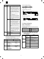
3. Hardware setup and adjustments
A. Flash Memory write protect setting
If communication between PC and the copier is not normally performed with the set value st to 10 (default), check the environment of
PC and change the set value.
Adjustment range: 0 ~ 255
Flash memory write protect setup (JP109)
Used to setup write protect YES/NO of flash memory.
JP109
JP109
1
3
Write protect condition
(Default)
1
(2) SELECT IN signal setup
3
Enter SIM 67-11 and set SELECT IN signal YES/NO.
The relationship between the set value (0 or 1) and SELECT IN
signal is as follows:
Write condition
Set value
0
1
When making version up of the flash memory or when rewriting the
flash memory, short pins 2-3. In normal cases, short pins 1-2 (write
protect).
When shipping, the DIP switch is set to the following value.
JP109
1-2
SELECT IN signal
YES
NO
If communication between PC and the copier is nor performed normally, check the environment of PC and change the set value.
Flash memory write protect
D. NVRAM clear
Use SIM 67-17.
This is used to clear various setup data relating to the printer operations stored in NVRAM on the printer control PWB.
Execute this procedure to set all the setup data to default.
B. Laser power setup
Enter SIM 61-4 and set the setup value to 16 (default).
If set to another value, normal print density may not be obtained.
C. Centro interface adjustment
E. Network card check
(1) Centro interface timing adjustment
After installing the network card, execute SIM 67-16, and the operation of the network card is displayed as NG or OK.
Enter SIM 67-3 and set the ACK signal width.
4–4
AR-PB2A
[5] Configuration Report and Test Page
1. Samples
b. Language
Value:
(English) | Deutsch (German) | Francais (French) |
Italiano (Italian) | Nederlands (Dutch) | Espanol
(Spanish) | Svenska (Swedish)
Example:
English
Default:
Depends on copier language
Description: AR-PB2 includes seven language messages originally.
AR-PB2 decides the display language depending on the
language code sent from MAIN (MAIN sends the language code based on its language ROM). This value
indicates the language that sent by MAIN to PRT.
2. Description of Each contents
This section defines the meaning of each item. These items are basically used in configuration pages, but some contents are not used
depending on language.
A. Hardware Status
Machine Information
a. Resolution
Value:
600 dpi
Example:
600 dpi
Default:
600 dpi
Description: It is always 600 dpi.
5–1
AR-PB2A
c. Paper Input Trays
Value:
(2 trays | 3 trays | 4 trays)
Example:
2 trays
Default:
Depends on the Machine configuration
Description: It indicates the number of standard input trays.It
depends on hardware configuration.
Hardware Specs
a. Base Memory
Value:
16 MB
Example:
16 MB
Default:
16 MB
Description: It indicates base memory quantity of the printer board.
Basically, this is fixed at 16 MB and it cannot be
changed.
d. Large Capacity Tray
Value:
(Yes | No)
Example:
Installed
Default:
Depends on the Machine configuration
Description: It indicates that large capacity paper input tray(Large
Capacity Tray) is attached or not. It depends on
hardware configuration.
b. Optional Memory
Value:
(0|16|32|48|64) MB
Example:
0MB
Default:
0MB
Description: It indicates the printer board’s optional memory quantity.
The customer (serviceman) could extend the memory
by attaching 72pin-SIMM. 0MB means optional memory
is not attached. 16MB or 32MB SIMM can be used to
this purpose.
e. Interface Board
Value:
(None | Ethernet | TokenRing)
Example:
Ethernet
Default:
Depends on the Machine configuration
Description: It indicates the kind of installed network card option to
the slot. 10Base-T/2 and 10/100Base-T are not identified. Those two will be reported as Ethernet.
TokenRing would not be supported for AR-PB1 (ARPB2) for Japan domestic.
c. Total Memory
Value:
(16|32|48|64|80) MB
Example:
16MB
Default:
16MB
Description: It indicates the printer board’s total memory quantity. In
other words, it is summation of Base Memory and Option Memory.
Available Paper Size
d. Copier HDD
Value:
4GB
Version Information
a. PRT
Value:
Example:
Default:
Description:
b. BOOT
Value:
Example:
Default:
c. ICU
Value:
Example:
Default:
Description:
#.##
2.00
Depends on printer firmware version
This number should be same as the PRT-PRG ROM
version number seen on serviceman simulation 22-5.
#.##
2.00
Depends on printer firmware version
#.##
2.00
Depends on printer firmware version
This number should be same as the ICU ROM version
number seen on serviceman simulation 22-5.
Installed Device
a. Duplex Module
Value:
(Yes | No)
Example:
Yes
Default:
Depends on the Machine configuration
Description: It indicates that duplex unit is attached or not.It depends
on hardware configuration.
Appearance on
Configuration Page
Description
Letter (81/2x11)
Letter / Long Edge Feed
Letter (81/2x11R)
Letter / Short Edge Feed
Legal (81/2x14)
Legal / Short Edge Feed
Ledger (11x17)
Ledger / Short Edge Feed
Executive (7 1/4x101/2)
Executive / Short Edge Feed
Invoice (5 1/2x81/2)
Invoice / Long Edge Feed
Foolscap (81/2x13)
Foolscap / Short Edge Feed1
A4
A4 / Long Edge Feed
A4R
A4 / Short Edge Feed
B5
B5 / Long Edge Feed
B5R
B5 / Short Edge Feed
B4
B4 / Short Edge Feed
A3
A3 / Short Edge Feed
A5
A5 / Long Edge Feed
A6
A6 / Short Edge Feed
Japanese Postcard
Japanese Postcard / Short Edge Feed
(Unknown)
Other size (EXTRA)
(No Paper)
No paper available on this tray.
(No Tray)
There is a problem with this tray.
(Tray Open)
This tray is opened (except Bypass-Tray)
or Tray is lifting up.
a. Tray 1 / Tray 2 / Tray 3 / Tray 4
Value:
[Appropriate Paper Size]
Example:
Letter (81/2x11)
Default:
Depends on paper tray configuration.
Description: It indicates paper size configuration of Tray 1 /2 / 3 / 4 /
5. It depends on hardware configuration, not software
condition.
(Unknown) means paper size cannot be identified. (Tray
configuration is "EXTRA".)
This line is not printed for unavailable tray.
b. Output Device
Value:
(Standard 1 Tray | Standard 2 Trays | 3 Tray Finisher|2
Tray Finisher)
Example:
3 Tray Finisher
Default:
Depends on the Machine configuration
Description: It indicates attached output device.. It depends on
hardware configuration.
5–2
AR-PB2A
b. Large Capacity Tray
Value:
[Appropriate Paper Size]
Example:
Letter (81/2x11)
Default:
Depends on paper tray configuration.
Description: It indicates paper size configuration of Large Capacity
Tray. It depends on hardware configuration, not
software condition. When tray is opened, nothing is
printed at here.
This line is not printed when Large Capacity Tray is not
attached.
c. Font
Value:
Example:
Default:
Description:
(PCL font name)
Courier
Courier
Current default font for PCL printing.
d. Pitch Size
Value:
# (variable length digit)
Example:
0.44 to 99.99 in 0.01 steps
Default:
10.00
Description: This is the current default pitch size for plain PCL job
stream.
c. Bypass-Tray
Value:
[Appropriate Paper Size]
Example:
Letter (81/2x11)
Default:
Depends on the paper size set on Bypass Tray.
Description: It indicates paper size of set on Bypass Tray. It depends
on detection of Bypass Tray paper size. (Unknown)
means paper size cannot be detected.
e. Point Size
Value:
# (variable length digit)
Example:
4.00 to 999.75 in 0.25 steps
Default:
12.00
Description: This is the current default point size for plain PCL job
stream.
B. Software Information
f. Symbol Set
Value:
(PCL symbol set name)
Example:
Roman-8
Default:
Roman-8
Description: This is the current default symbol set for plain PCL job
stream.
PostScript Emulation
a. Job Time-out
Value:
# (variable length digit)
Example:
0
Default:
0
Description: This value indicates PostScript Job Time-out length
(seconds). If this time will pass from receiving the job
then PostScript interpreter will give up to print the job
and cancel.
Network Information
a. NIC Serial Number
Value:
######
Example:
123456
Default:
Depends on NIC.
Description: It indicates the NIC’s serial number. This value is written
in NIC’s ROM (or flush ROM).
b. Manual Feed Time-out
Value:
# (variable length digit)
Example:
0
Default:
0
Description: This value indicates PostScript Manual Feed Time-out
length (seconds). If the print data break off during printing and this time will pass, then PostScript interpreter
will cancel the print job. 0 means never time out.
b. NIC Firmware Version
Value:
######
Example:
123456
Default:
Depends on NIC.
Description: It indicates the NIC’s serial number. This value is written
in NIC’s ROM (or flush ROM).
c. Wait Time-out
Value:
# (variable length digit)
Example:
300
Default:
300
Description: This value indicates PostScript Wait Time-out length
(seconds). If the print data break off during printing and
this time will pass, then PostScript interpreter will cancel
the print job. 0 means never time out.
c. NetWare Print Server Name
Value:
[User Definable]
Example:
SHARP_990792
Default:
SHARP_[NIC card serial number]
Description: This value must reflect the printer name for IPX/SPX
(NetWare).
PCL5e Emulation
This section tells PCL5e information. This section would not appear
on AR-PB1 (Siam) for Japan domestic.
a. Font Source
Value:
(Resident | Download)
Example:
Resident
Default:
Resident
Description: Current font source to print characters in PCL mode.
b. Font Number
Value:
0 to 45
Example:
0
Default:
0
Description: This is the current default font number used for plain
PCL job stream.
5–3
AR-PB2A
2. Network card
[6] FIRMWARE VERSION UP
When using the network card AR-NC3D with AR-PB2A, if the
firmware version of the AR-NC3D is 5.46 or earlier, upgrade is
needed.
This upgrade must be carried out for adapting the card to the additional features of AR-PB2A.
Check the version number in accordance with step 1 and carry out
the upgrade in accordance with step 2 if needed.
1. Printer controll PWB
A. Cases where flash memory rewriting is required
In the following cases, the program in the printer control PWB flash
memory must be rewritten.
1) When a bug or other error is found
2) Data stored in the flash memory is destroyed or deleted.
3) When the flash memory is replaced.
A. Check the version number of the network card.
Select the menu by pressing "MENU" and "PRINT TEST PAGE" on
the operation panel of the copier and execute "PRINT CONFIGURATION PAGE".
The setting list will be printed. Check "NIC Firmware Version:" in
"Network Information".
If the version number is 5.46 or less, upgrade is needed.
B. Necessary tools
1) Computer (PC)
2) Parallel cable
3) Program data file (xxx.hex)
C. Procedure
B. Upgrade of network card The upgrade tool is
included in the PRINTER UTILITIES CD-ROM.
1) Print the setup list to check the firmware version.
Use the operation panel of the copier to perform the following
procedure.
Offline → Environment setup → Test page print → Test page
output
2) Turn off the power and cancel write protect of the flash memory on
the printer control PWB.
Copier power OFF → Remove the printer control PWB. → Switch
the connection of jumper JP109 on the printer control PWB from
1-2 to 2-3. → Install the printer control PWB.
3) Connect the PC and the copier with the parallel cable.
4) Turn on the power
5) Execute SIM 67-14.
6) Download the program file.
(Note) Never turn off the power during download.
Set the PC to DOS mode → Check that the display shows
READY. → Then type > COPY
xxx.hex LPT1:
and press the enter key.
(
:space)
Since this file is used for service, it is set as a hidden file. Check the
file using the following procedure.
1) When checking on a Windows PC, select "Show all files" from the
"View" and "Folder Options" menus.
2) The tool is included in the "\NC3D" folder. Carry out the upgrade
of the network card in accordance with the Network Card Upgrade
Utility Manual ("FTPDLMAN.TXT").
The display is changed as shown below and the final display
shows OL. Then the simulation is completed.
READY → RECEIVE → ERASE → BLANK → WRITE →
VERIFY → OK
(Note) In case of an error, "NG" is displayed.
IN that case, press the interruption key to exit from SIM 67-12
menu.
If the PC still sends data, stop data sending.
Check the PC and the copier for any abnormality, and perform the above procedure again. It is requred 15 ∼ 30 min.
(Due to PC performance)
7) Print the setup list and check the firmware version.
8) Turn off the power and write-protect the flash memory on the
printer control PWB.
Copier power OFF → Remove the printer control PWB. → Switch
the connection of jumper JP109 on the printer control PWB from
1-2 to 2-3. → Install the printer control PWB.
9) Perform printing on the PC side and check that printing is performed normally.
6–1
AR-PB2A
[7] FUNCTION AND OPERATION
1. Multi Function
Multiple Functions
Arbitration of contention among printing, copying and faxing is controlled by the copier. The print controller only sends the print request to the copier.
The copier judges whether the requested print job is immediately performed or not by checking the current status of the copier. The printer controller
does not control contention caused by the status of the copier.
(1) Printer/Copier
From Printer Job to Copier Job
New Job
Current Job
Panel operation
(Copier)
Copy scan (scanning an original to
be copied )
(Copier)
Memory copy (saving
copy data into memory)
(Copier)
Copy Printing
(Copier)
Receiving Print Data
(PRT)
Enables copy panel
operation without
interruption.
Continually receiving
print data.
Enables copy scanning without
interruption.
Continually receiving print data.
Enables saving of copy
data into memory without
interruption.
Continually receiving
print data.
Enables copy printing
without interruption.
Continually receiving
print data.
Rasterizing Print Data
(PRT)
Enables panel operation
without interruption.
Continually rasterizing
print data.
Enables copy scanning without
interruption.
Continually rasterizing print data.
Enables saving of copy
data into memory without
interruption.
Continually rasterizing
print data.
Enables copy printing
without interruption.
Continually rasterizing
print data.
Transferring Print Image
(PRT-Copier)
Enables copy panel
operation without
interruption while the first
page of data is being
transferred.
Allows interrupt copy
panel operation while
print data of the second
or successive pages is
being transferred.
Enables scanning without
interruption while the first page of
data is being transferred.
Allows interrupt copying (copy
scan) while print data of the
second or successive pages is
being transferred.
In either case, clears transferred
image data and requests that the
image data be transferred again.
Enables saving of copy data into
memory without interruption while
the first page of data is being
transferred.
Allows interruption of saving of
copy data into memory while print
data of the second or successive
pages is being transferred.
In either case, clears transferred
image data and requests that the
image data be transferred again.
Enables copy printing
without interruption while
the first page of data is
being transferred.
Allows interrupt copy
printing while print data of
the second or successive
pages is being
transferred.
In either case, clears
transferred image data
and requests that the
image data be
transferred again.
Printing Images
(Copier)
Enables copy panel
operation without
interruption.
Continually transferring
the print image.
After the current page is printed
After the current page is
out, allows interruption of scanning. printed out, allows
interruption of saving of
copy data into memory.
After the current page is
printed out, allows
interruption of copy
printing.
From Copier Job to Printer Job
New Job
Current Job
Receiving Print Data
(PRT)
Rasterizing Print Data
(PRT)
Transferring Print Image
(PRT-Copier)
Printing Images
(Copier)
Copy panel operation
(Copier)
Continually receiving print
data until receiving buffer
becomes full.
Continually rasterizing print
data until image buffer
becomes full.
Disables print image
transfer.
Disables print image
printing.
Copy scan (scanning an
original to be copied)
(Copier)
Continually receiving print
data until receiving buffer
becomes full.
Continually rasterizing print
data until image buffer
becomes full.
Disables print image
transfer.
Disables print image
printing.
Memory copy (saving
copy data into memory)
(Copier)
Continually receiving print
data until receiving buffer
becomes full.
Continually rasterizing print
data until image buffer
becomes full.
Disables print image
transfer.
Disables print image
printing.
Copy Printing
(Copier)
Continually receiving print
data until receiving buffer
becomes full.
Continually rasterizing print
data until image buffer
becomes full.
Disables print image
transfer.
Disables print image
printing.
7–1
AR-PB2A
2. Printer Operation / Message Display
During initializing the printer board
From the end of initialization to the end of warm-up.
During the warm-up and waiting for starting a print job with
the data receiving /processing completed
During the idle
(Online with no data being received / printed)
During receiving the data
During processing the data
During transferring images to ERDH
During the output of print
(during printing the data stored in ERDH)
During suspending the print
(from when the print starts to be suspended by user’s
instruction during printing and to when the print job can be
actually stopped.
While the print is suspended by user.
(the data is held)
While the print data is being cleared.
(Job Cancel)
Offline
(The state in which no data is being received and printed,
and the user instruction causes Offline.)
When there is no paper in Bypass Tray during suspending
a job with Bypass Tray (manual) selected.
(The data is held.)
When there is paper in Bypass Tray during suspending a
job with Bypass Tray (manual) selected.
(The data is held.)
When there is no paper in Bypass Tray selected at the start
of printing the data, or when the print is suspended due to
paper-out.
(The data is held.)
When there is no paper in the selected tray at the start of
printing the data, or when the print is suspended due to
paper-out.
(The data is held.)
When Staple Unit is not installed properly
(the data is held)
When a stapler is empty (AR-FN1)
(The data is held.)
When a stapler is empty (AR-FN2)
(The data is held)
During suspending the print due to some errors
( Jam/Toner supply)
(The data is held)
JOB
Cancel/(Clear)
Paper Selection
Disabled
Online
LED
Data
LED
Off
Off
Disabled
Disabled
Off
On
Off / On
On
READY TO PRINT.)
Disabled
On
Off
PROCESSING PRINT DATA.
Disabled
On
Blink
PRINTING IN PROGRESS.
Disabled
On
Blink
<Displayed on a dialog window>
PRINTING IN PROGRESS.
PLEASE WAIT.
Disabled
Blink
Blink
OFFLINE.
TO CLEAR DATA, PRESS [C].
PLEASE WAIT.
DATA IS BEING CLEARED.
OFFLINE.
Enabled
Off
On
Enabled
Off
On
Disabled
Off
Off
ADD ******** PAPER INTO BYPASS-TRAY.
(When supplying paper as directed, the print
will start in three seconds. However, since
the size detection is not performed, the
paper sizes other than selected one will start
to be printed.)
CHANGE BYPASS-TRAY PAPER TO
********.
(When supplying paper as directed, the print
will start in three seconds. Even if the paper
in bypass tray continues to be used , the
paper needs to be reset by loading it again.
However, since the size detection is not
performed, the paper sizes other than
selected one will start to be printed.)
ADD ******** PAPER INTO BYPASS-TRAY.
(When supplying paper as directed, the print
will automatically restart in three seconds.)
Enabled
Off
On
Enabled
Off
On
Enabled
Off
On
OPEN * TRAY AND ADD PAPER.
(When supplying paper as directed, the print
will automatically restart after the lift-up
operation in the tray.)
CHECK STAPLER POSITION OR STAPLE
JAM.
(When checking and setting properly as
directed, the print will automatically restart.)
SLIDE THE FINISHER AWAY FROM THE
COPIER AND ADD STAPLES.
(when checking and setting properly as
directed, the print will automatically restart.)
ADD STAPLES.
(When checking and setting properly as
directed, the print will automatically restart.)
Enabled
Off
On
Enabled
Off
On
Enabled
Off
On
Enabled
Off
On
Disabled
Off
On
State
Display
<Displayed on dialog window>
INITIALIZING. PLEASE WAIT.
WARMING UP. PLEASE WAIT
PLEASE WAIT.
<CONFORM TO COPIER OPERATION
SPECIFICATION.>
(Print will start just as the trouble is removed.)
7–2
AR-PB2A
3. Emulation Switch
5. Font
Emulation setting can be switched between automatic emulation
sensing (switching) and fixed emulation modes as shown below.
A. Downloadable Font Types
The Cougar printing system supports the font types for download.
AR-PB2
Page Description
Language
Automatic (PCL ↔ PS)
PCL (fixed)
/ PostScript (fixed)
PCL 5e
TrueType
Bitmap
Intellifont
PostScript Level 2
Type 1
Bitmap
Type 42
Emulation switching is performed in the following manner.
Emulation Setting
PJL
Command for Specified
Automatic
Specifying an Emulation
Automatic
Emulation
Sensing
Uses the
emulation
automatically
selected.
OK
No
Fixed
B. Location of Font Data
Uses a default
emulation.
Font Data
Uses the emulation specified.
Yes
Yes
PCL Roman 80 Fonts
PS Roman 80 Fonts
Uses PCL
Uses the
emulation
specified.
3MB
The printing system will automatically switch to the correct emulation
or switch to the fixed emulation mode.
Emulation setting mode
Fixed
1
PS/PCL
B. Job, control
The job control commands support PJL (Printer Job Language) which
HP printers include. PJL is available for all emulations (PCL5e,PostScript).
7. Host I/O Port Selection
There are two host I/O ports, the P1284 port and the Network(NIC)
port, as described before. The host I/O port can be selected between
the I/O port automatic port switching and the I/O fixed port setting.
The automatic port switching has two settings, between jobs and after
I/O time-out.
Main Scan
300dpi
(1 dot)
AR-PB2
PS ↔ PCL
Automatic
The printer controller supports only 600-dpi binary images in single bit
per pixel mode. The print engine does not support resolution settings
other than 600 dpi (fixed at 600 dpi). When300 dpi is specified for
resolution, 4 pixels are represented as 1 dot to create 300dpi image.
In other words, the printer controller always sends 600-dpi images to
the engine.
Sub Scan
Flash ROM #5
A. Language Selection
Uses a default
emulation.
4. Resolution
600dpi
(1 dot)
Size
6. Language
In the automatic emulation sensing mode, for print data without the
PJL command, the emulation is automatically switched either to PostScript, to PCL5e based on data sensed. In other words, automatic
emulation sensing (switching) is available only between PostScript
and PCL5e. For print data with the PJL command, the emulation is
automatically switched to the specified one with out sensing the data.
When print data without the PJL command fails to be sensed, or
when the print data is given the PJL command but the specified
emulation is not present, the data is handled in the PCL emulation.
In the fixed emulation mode, for print data without the PJL command,
the fixed emulation is used to handle the print data.Print data with the
PJL command is switched to the specified emulation. When print data
is given the PJL command but the specified emulation is not present,
the data is processed by the default emulation.
The PJL Enter command specifies PostScript and PCL5e.
Main Scan
Hardware
Uses PCL
NG
No
AR-PB2
Reference
Position
Sub Scan
7–3
AR-PB2A
Setting
[Example of Automatic Switching]
Behavior
Automatic Between
Switching Jobs
Receiving Port
When receiving data is detected through
a port, sensing data receipt from each
port, considers the port as current (port
automatic sensing processing), and
processes the data received only through
the current port. Then until the job ends
in the situation described below in 1) or
2), the data through the current port is
only processed. After the print job ends,
the port automatic sensing processing
restarts.
NIC Port
Job2:
1284 Port
No
Job3:
NIC Port
Yes
Receive Job1
NIC
Job2
Disables
Network
(NIC) Port
Receives data only through the P1284
port.
2) Automatic - After I/O Time Out
Receive Job1
NIC
PCL
• PJL ENTER
LANGUAGE
command (PCL)
• Jobs starting with the
PCL data
PS
• PJL ENTER
LANGUAGE
command
(POSTSCRIPT)
• Jobs starting with the
PostScript data.
Receive Job3
Job3
Job1
Job2
↔
↔
I/O Timeout
Receive to Buffer
Receive Job2
13. Memory Configuration
The following ROM are supported.
EPROM:
Boot & Simulation Program
Flash ROM: Program &Font data
Boot ROM is selectable between EPROM and Flash ROM #5 using
the jumper switching.
Flash ROM #5
4MB
Main Program
Flash ROM #5
3MB
PCL Roman 80 Fonts
PS Roman 80 Fonts
Flash ROM #5
1MB
Boot/Simulation Program
14. Printer control PWB switch (short pin)
and LED display
Switch
LED
Job End
↔
I/O Timeout
1284
Switch, LED
Job Start
• PJL JOB command
Job End Data
Wait
Note: In the I/O time-out, the count starts at the point that data is not
acquired via the receiving buffer. When receiving the data until
the I/O time-out, the count is reset to stop.
In the between jobs setting of the automatic switching, the
conditions that a print job will be completed are as follows.
Common
I/O Timeout
Receive Job2
1) The current port gets into the state of
waiting for data receipt, and after no
data is received for a certain time (I/O
time-out value), the print job ends by
the I/O time-out. (When the print job
has not been completed , it ends
simultaneously.
Receives data only through the Network
(NIC) port.
Job3
Receive to Buffer
When receiving data is detected through
a port, sensing data receipt from each
port, considers the port as current (port
automatic sensing processing) and
processes the data received only through
the current port. Then until the I/O
time-out in the situation described below
in 1), the data through the current port is
only processed. After the I/O time-out,
the port automatic sensing processing
restarts.
Disables
P1284 Port
Receive Job3
Job1
1284
2) The current port gets into the state of
waiting for data receipt, and after no
data is received for a certain time (I/O
time-out value), print job ends by the
I/O time-out.
Fixed
Yes
1) Automatic Switching - Between Jobs
1) The print job is completed by the
job-end command.
After I/O
Time-out
Job End Data
Job1:
• PJL EOJ command
• I/O Timeout
Software
status
• UEL command
• <ESC>E
• I/O Timeout
• UEL command
• <Ctrl-D>
• I/O Timeout
7–4
Function
RESET switch
(SW102)
Processor and peripheral device
initialization
ABORT switch
(SW101)
MMI* generation to processor
POWER-LED
(D114)
PWB power ON. Lighted when
supplying power.
RUN-LED
(D113)
Processor operating status.
Lights up when operating.
STO-LED
(D109)
Lights UPD71055-A port 0 bit 4 at
"0."
ST1-LED
(D110)
Lights UPD71055-A port 0 bit 5 at
"0."
ST2-LED
(D111)
Lights UPD71055-A port 0 bit 6 at
"0."
ST3-LED
(D112)
Lights UPD71055-A port 0 bit 7 at
"0."
AR-PB2A
15. Confidential Print
The confidential print feature allows printing to be started only after
entering the specified password on the operation panel. This feature
is useful for printing secret document data on the printer located away
from the user.
To execute confidential print, specify use of this feature and enter a
password on the setting screen of the printer driver (Advanced tab in
the Windows system, print conditions setting in the Macintosh system). The operation procedure on the operation panel for starting
confidential print is described below. The maximum number of confidential print jobs that can be stored in the printer can be specified
using a key operator program.
NOTES: Different first page, transparency inserts, and booklet print
are not available with this feature.
Paper tray selection in the printer driver must be ’Auto
Select’.
A confidential print data is deleted when printing is completed or the CLEAR () key is pressed during printing.
If the printer power switch is turned off or the printer is
turned off by the auto power shut-off function, all confidential print data that has been stored in the printer will be
deleted. The auto power shut-off time can be adjusted
using a copier key operator program. If confidential print is
often used, it is recommended to set a long auto power
shut-off time.
In the following cases, the printer will cancel confidential
print and output a notice page. The received print data will
be cleared.
1. The maximum number of print jobs or the maximum
number of pages specified with a key operator program
is exceeded.
2. ‘Custom paper size’ is specified.
16. Tandem Print
If the printer model has the tandem copy/print feature and is connected with another copier of the same model through the tandemconnection cable so that the tandem copy feature can be used, the
tandem print feature can be used. For printing multiple sets, two
printers can be used simultaneously, allowing printing to be twice as
fast as printing on one printer.
To execute tandem print, select this feature on the printer driver setting screen (Advanced tab in the Windows system, print conditions
setting in the Macintosh system).
• If the printers are equipped with optional equipment, the two
printers must be equipped with the same optional equipment. A
dedicated tandem-connection cable AR-CA1 is required for tandem print.
• Paper tray selection in the printer driver must be ‘Auto Select’.
• Different first page, transparency inserts, and confidential print are
not available.
NOTES: If the printers are connected to the network, print data must
be sent to the main printer for tandem print. If the data is
sent to the sub printer, the data will be output without using
the tandem print feature.
For tandem printing, the operation settings of the two
copier/printers must be the same. For details on these settings, see the section of Tandem Copy in the copier operation manual.
To cancel tandem printing after starting, press the "OFFLINE" key on the main printer. Then press the CLEAR key
on the main printer.
7–5
AR-PB2A
(Error message)
F9
0
Content
ICU-PRT communication trouble
Detail
F9
F9
F9
F9
F9
F9
F9
01
02
03
04
05
10
90
Cause
SCSI LSI abnormality
ICU PWB defect
SCSI connector connection defect
Printer PWB defect
Check and remedy
Replace the printer PWB.
Check the SCSI connector.
Replace the printer PWB.
Replace the ICU PWB.
Content
PRT DRAM trouble
Detail
DRAM trouble in the option printer board. (When operating the scanner mode)
Cause
DRAM module is broken and access cannot be made.
DRAm module installation trouble
Check and remedy
Check with SIM 57-1.
Content
PRT Centro port check error
Detail
Option printer board Centro port trouble
Cause
Centro port defect
Printer PWB defect
Check and remedy
Replace the printer board.
Content
Network card trouble.
Detail
Network card self test trouble.
Cause
Network card defecft.
Printer PWB defect.
Network card connector connection defect.
Check and remedy
Check the Network card connector.
Replace the printer PWB.
Replace the Network card.
Content
Printer program error.
Detail
Program data trouble in the option printer board.
Cause
Flash memory data is destroied.
Check and remedy
Replace or rewrite the Flash memory.
Replace the printer PWB.
Content
Short of memory capacity on the ICU PWB
Detail
Total memory is less than 16MB on the ICU PWB.
Cause
Memory defect
SIMM memory connector connection defect
ICU PWB defect
Wrong type SIMM memory is installed
Check and remedy
Replace the ICU PWB
Replace the memory
Check the memory connector
Content
PRT SCSI LSI abnormality
Detail
An error occurred in SCSI communication with the option printer board.
Cause
SCSI LSI abnormality
ICU PWB defect
Printer PWB defect
SCSI connector connection defect
Check and remedy
Replace the printer PWB.
Check the SCSI connector.
Replace the printer PWB.
Replace the ICU PWB.
Content
ICU-PRT communication trouble (PRT detection)
Detail
Cause
SCSI LSI abnormality
ICU PWB defect
SCSI connector connection defect
Printer PWB defect
Check and remedy
Replace the printer PWB.
Check the SCSI connector.
Replace the printer PWB.
Replace the ICU PWB.
PARTS GUIDE
MODEL
AR-PB1/PB1A
AR-PB2/PB2A
CONTENTS
(Printer unit)
(Printer PWB)
(Packing material & Accessories)
(Index)
SHARP CORPORATION
This document has been published to be
used for after sales service only.
The contents are subject to change without
notice.
DEFINITION
The definition of each Rank is as follows and also noted in the list
A : Parts necessary to be stocked as High usage parts.
B : Parts necessary to be stocked as Standard usage parts.
C : Low usage parts.
D : Parts necessary for refurbish.
E : Unit parts recommended to be stocked for efficient after sales service.
Please note that the lead time for the said parts may be longer than normal parts.
S : Consumable parts.
Please note that the following parts used in Copier under the same description are classified into A or B Rank depending
upon the place used.
Example : Gear made of Metal, Sprocket, Bearing, Belt made of Rubber, Spring clutch mechanism.
A Rank : The parts which may be with the revolution or loading.
B Rank : Parts similar to A Rank parts, but are not included in Rank A.
Because parts marked with “ ” is indispensable for the machine safety maintenance and operation, it must be replaced with
the parts specific to the product specification.
1
(Printer unit)
NO.
1
2
3
4
5
6
7
8
9
10
11
12
13
14
16
17
PARTS CODE
PRICE RANK NEW PART
DESCRIPTION
Ex.
Ja. MARK RANK
Printer box fan
BA
FX
B
Washer
AA
DD
C
Screw (3×24)
AA
DD
C
Screw (3×6)
AA
DD
C
Printer mother PWB
AY
FQ
E
Printer power supply harness
AU
EZ
C
Printer box cover
AX
FG
C
Printer box base
AT
EZ
C
Screw (3×6)
AA
DD
C
Network board cover
AE
DS
C
Screw (2.5×8)
AA
DD
C
Gasket (UC-3E1259T)
AK
EB
C
Printer box side plate
AH
DX
C
Handle fixing screw
AD
DJ
C
Flash ROM (28F322-02F)(Japan only)
(AR-PB1A/PB1)[CN107]
CA
TV
B
Flash ROM (28F322-01F)(Except Japan) (AR-PB2A/PB2)[CN107]
CA
TV
B
Network interface PWB
AX
FG
E
–1–
ROM
ROM
1
(Printer unit)
9
14
3
1
8
2
9
13
4
10
6
7
12
14
5
11
9
4
16
4
4
17
4
FCP04237
2
4
4
(Printer PWB)
NO.
1
2
3
4
5
6
7
8
9
10
11
12
13
14
15
16
17
18
19
20
21
22
23
24
25
26
27
28
29
30
31
32
33
34
35
36
37
38
39
40
41
42
43
44
PARTS CODE
PRICE RANK NEW PART
DESCRIPTION
Ex.
Ja. MARK RANK
PWB holder (SRF5U)
AD
DJ
C
Cap (JM-2W-96)
[JP109]
AD
DJ
C
Heat sink (PUG16-25)
[IC166]
AG
DS
C
Sheet (2067B)
[IC166]
AC
DJ
C
Connector (53319-0200)(20pin)
[CN116]
AH
DX
C
Connector (DHB-PB60)(60pin)
[CN105]
AQ
EG
C
Connector (36pin)
[CN101] 36PIN
AH
DX
C
Connector (PCSXE50LFDT)(40pin)
[CN102]
AP
EQ
C
Pin (T3B-SQ)
[JP109]
AC
DJ
C
Push memory socket (93674-51872)
[CN107]
AN
EG
C
Push memory socket (93674-51872)
AN
EG
C
(AR-PB1A/PB1)[CN108,110,111,114]
SIMM socket (917970-1)
[CN109,113] SIMM
AL
EB
C
IC socket (28pin)
[IC142] IC
AE
DS
C
Crystal (40MHz)
[X103]
AQ
EQ
B
Crystal (74.9MHz)
[X101]
AR
EQ
B
Block resistor (4.7KΩ×8)
[BR217,220]
AC
DD
B
Block resistor (10KΩ×8)
[BR202,203,205∼216,218,219,221∼245]
AC
DD
B
Block resister (2KΩ×8)
[BR201]
AC
DD
B
Block resister (2.2KΩ×8)
[BR204]
AC
DD
B
Capacitor (50WV 100pF)
[C281]
AA
DD
C
Capacitor (50WV 30PF)
[C376]
AB
DD
C
Capacitor (10WV 1.0µF)
[C302,303,315,316]
AC
DD
C
Capacitor (6.3WV 100µF)
[C107]
AC
DD
C
Capacitor (16WV 10µF)
[C102,103,109]
AC
DD
C
Capacitor (16WV 47µF)
[C104,106]
AC
DJ
C
Capacitor (25WV 35µF)
[C105]
AC
DD
C
Capacitor (50WV 10µF)
[C101,108]
AD
DD
C
Capacitor (25WV 0.10µF)
AA
DD
C
[C201,202,203,205,206,215,216,222∼229,234∼240,242∼258]
Capacitor (25WV 0.10µF)
AA
DD
C
[C260∼280,282∼299,304∼312,314,317∼368]
Capacitor (25WV 0.10µF)
[C370∼373,379∼426]
AA
DD
C
Capacitor (50WV 1000pF)
[C300,230]
AA
DD
C
Capacitor (50WV 0.010µF)
[C301]
AA
DD
C
Capacitor (50WV 2200pF)
[C207∼214]
AA
DD
C
Diode (1N4005)
[D101∼104,106]
AB
DJ
B
Diode (1SS133)
[D107]
AA
DD
B
Diode (SB140)
[D105]
AF
DS
B
IC (162244ATPV)
[IC136] IC
AR
EQ
B
IC (162245ATPV)
[IC123,124,133,135] IC
AS
EQ
B
IC (162373ATPV)
[IC105,120,122,129,134,143,144,145,146] IC
AS
EQ
B
IC (162511ATPV)
[IC138,139,140,141] IC
AV
FG
B
IC (1816-6)
[IC150,152,153,159,160,161,162] IC
AZ
FQ
B
IC (53CF96-2)
[IC114] IC
BH
HC
B
IC (74F74SJ)
[IC149] IC
AE
DS
B
IC (74LS245NS1)
[IC201] IC
AF
EB
B
IC (74LVT244NS)
[IC104] IC
AR
EQ
B
EEP ROM (AT28C64B)
[IC142] EEP ROM
AZ
FQ
B
IC (CLCD1283QC)
[IC106] IC
BF
GN
B
–2–
2
(Printer PWB)
NO.
PARTS CODE
45
46
47
48
49
50
51
52
53
54
55
56
57
58
59
60
61
62
63
64
65
66
67
68
69
70
71
72
73
74
75
501
PRICE RANK NEW PART
DESCRIPTION
Ex.
Ja. MARK RANK
IC (FCT244ATS0)
[IC101,148] IC
AN
EG
B
IC (GT64010AP1)
[IC125] IC
CB
TX
B
IC (LT1084CT)
[IC166] IC
BA
FX
B
IC (QS3L384)
[IC102,109,110,111,112,113,115,116,117,118] IC
AP
EQ
B
IC (RV470015MS)
[IC126] IC
BV
NU
B
IC (SN74LS14NS)
[IC156] IC
AL
EG
B
IC (SN74LS244S)
[IC107,108] IC
AF
DS
B
IC (T16244ATPV)
[IC147] IC
AR
EQ
B
IC (TC190G7034)
[IC128] IC
BB
GD
B
IC (TD62504F)
[IC164] IC
AF
DS
B
IC (UPD71051G)
[IC127,130] IC
AP
EQ
B
LED (GL3PR8)(red)
[D109∼114]
AA
DD
B
Resistor (1/16W 0Ω ±5%)
AA
DD
C
[R216,426,427,428,432,433,434,328,400,299,388,323,336∼339]
Resistor (1/16W 0Ω ±5%)
AA
DD
C
[R341,342,316,319,321,322,348,383,390,429,430,431,218,461]
Resistor (1/16W 10Ω ±5%)
[R103,104,344,347]
AA
DD
C
Resistor (1/16W 100Ω ±5%)
[R384,385,386,387]
AA
DD
C
Resistor (1/16W 1.0KΩ ±5%)
AA
DD
C
[R263,391,393,398,399,404,405,410,415,208,266,267,268,272,416]
Resistor (1/16W 10KΩ ±5%)
AA
DD
C
[R201∼203,213,214,270,271,273∼275,280∼291]
Resistor (1/16W 10KΩ ±5%)
AA
DD
C
[R293∼297,301∼304,306∼315,325,326]
Resistor (1/16W 10KΩ ±5%)
AA
DD
C
[R331∼333,350∼363,389,392,401,406∼409]
Resistor (1/16W 10KΩ ±5%)
[R411∼414,418∼421,460,467,468]
AA
DD
C
Resistor (1/16W 1.2KΩ ±5%)
[R265]
AA
DD
C
Resistor (1/16W 15OΩ ±5%)
[R210]
AA
DD
C
Resistor (1/16W 22Ω ±5%)
[R292,327,330,365,373,375,397,264]
AA
DD
C
Resistor (1/16W 33Ω ±5%)
AA
DD
C
[R204∼207,237∼244,370∼372,380,435∼458]
Resistor (1/16W 3.3KΩ ±5%)
[R279]
AA
DD
C
Resistor (1/16W 33KΩ ±5%)
[R403]
AA
DD
C
Resistor (1/16W 47Ω ±5%)
[R366∼369,376∼379,381,382]
AA
DD
C
Resistor (1/16W 470Ω ±5%)
[R345,346,417,422∼425]
AA
DD
C
Resistor (1/16W 4.7KΩ ±5%)
[R305,324]
AA
DD
C
Resistor (1/16W 47KΩ ±5%)
[R402]
AA
DD
C
Resistor (1/16W 5.6KΩ ±5%)
[R396]
AA
DD
C
Resistor (1/4W 220Ω ±5%)
[R219∼236]
AA
DD
C
Resistor (1/4W 330Ω ±5%)
[R245∼262]
AA
DD
C
Screw (3×6)
[IC166]
AA
DD
C
FN1 Mask ROM Unit (Japan only)
(AR-PB1A/PB1)[CN114] FN1
BB
GD
E
FN2 Mask ROM Unit (Japan only)
(AR-PB1A/PB1)[CN111] FN2
BB
GD
E
FN3 Mask ROM Unit (Japan only)
(AR-PB1A/PB1)[CN110] FN3
BB
GD
E
FN4 Mask ROM Unit (Japan only)
(AR-PB1A/PB1)[CN108] FN4
BB
GD
E
(Unit)
CZ
901
CZ
3
∗∗
∗∗
E
E
Printer PWB unit (Japan only AR-PB1A/PB1) [Not include No.501]
Printer PWB unit (Except japan AR-PB2A/PB2)
[Not include No.501]
ROM
ROM
ROM
ROM
PWB
PWB
(Packing material & Accessories)
NO.
1
2
3
4
5
6
7
8
10
12
13
PARTS CODE
PRICE RANK NEW PART
DESCRIPTION
Ex.
Ja. MARK RANK
Wire holder (LWS3S2W)
AC
DJ
C
Wire band (CV-150)
AB
DJ
C
Screw (3×4)
AA
DD
C
Connector caution label (Except USA,CANADA)
(AR-PB2A/PB2)
AG
DX
C
Vinyl bag (120×180mm)
AA
DD
D
Inst.card (Japanese)(Japan)
(AR-PB1A)
AE
DS
N
D
Inst.card (Japanese)(Japan)
(AR-PB1)
AD
DJ
D
Inst.card (English)(USA,CANADA,Europe,Australia,New Zealand)
AC
DJ
N
D
(AR-PB2A)
Inst.card (English)(USA,CANADA,Europe,Australia,New Zealand)
AC
DJ
D
(AR-PB2)
Inst.card (E,F,G,S)(CANADA,Europe,Others)
(AR-PB2A)
AH
DX
N
D
Inst.card (E,F,G,S)(CANADA,Europe,Others)
(AR-PB2)
AH
DX
D
ARNC3D inst.card (Japanese)(Japan)
(AR-PB1A) ARNC3D
AD
DJ
N
D
ARNC3D inst.card (English)
AC
DJ
N
D
(USA,CANADA,Europe,Australia,New Zealand)
(AR-PB2A) ARNC3D
ARNC3D inst.card (E,F,G,S)(CANADA,Europe,Others) (AR-PB2A) ARNC3D
AE
DJ
N
D
FAX interface cable
FAX
BC
GJ
C
Vinyl bag (140×260mm)
AA
DD
D
Accessories sleeve
AG
DS
D
Spacer
AL
EB
D
Operation manual (Japan only)
(AR-PB1A)
AZ
ZZ
N
D
Operation manual (Japan only)
(AR-PB1)
AY
ZZ
D
Operation manual (English)(USA,CANADA)
(AR-PB2A)
AT
EZ
N
D
Operation manual (English)(USA,CANADA)
(AR-PB2)
AQ
EQ
D
Operation manual (English)(Australia,New Zealand,Europe)
AT
EZ
N
D
(AR-PB2A)
–3–
J
J
U
U
E4
E4
J
U
E4
E
E
EG
3
(Packing material & Accessories)
NO.
PRICE RANK NEW PART
Ex.
Ja. MARK RANK
PARTS CODE
13
14
15
16
17
18
19
20
3
AQ
EQ
AX
AV
AX
AV
AX
AV
AX
AV
AX
AV
AX
AV
AA
AE
AF
AH
AD
AF
AL
AP
AL
AP
AL
AP
AL
AP
AL
AP
AL
AP
AL
AP
AL
AP
AL
AP
AL
AP
FG
FG
FG
FG
FG
FG
FG
FG
FG
FG
FG
FG
DD
DS
DS
DX
DJ
DS
EB
EQ
EB
EQ
EB
EQ
EB
EQ
EB
EQ
EB
EQ
EB
EQ
EB
EQ
EB
EQ
EB
EQ
D
N
D
D
D
D
D
D
D
D
D
D
D
D
D
D
D
D
D
D
D
D
D
D
D
D
D
D
D
D
D
D
D
D
D
D
D
D
D
D
N
N
N
N
N
N
N
N
N
N
N
N
N
N
N
DESCRIPTION
Operation manual (English)(Australia,New Zealand,Europe)
(AR-PB2)
Operation manual (French)(CANADA,Europe)
(AR-PB2A)
Operation manual (French)(CANADA,Europe)
(AR-PB2)
Operation manual (German)(For Europe)
(AR-PB2A)
Operation manual (German)(For Europe)
(AR-PB2)
Operation manual (Dutch)(For Europe)
(AR-PB2A)
Operation manual (Dutch)(For Europe)
(AR-PB2)
Operation manual (Spanish)(For Europe)
(AR-PB2A)
Operation manual (Spanish)(For Europe)
(AR-PB2)
Operation manual (Italian)(For Europe)
(AR-PB2A)
Operation manual (Italian)(For Europe)
(AR-PB2)
Operation manual (Swedish)(For Europe)
(AR-PB2A)
Operation manual (Swedish)(For Europe)
(AR-PB2)
Vinyl bag (230×340mm)
Vinyl bag (460×500mm)
Protection packing cushion B
Packing cushion
Protection packing cushion A
Spacer
Packing case (Japnese)(Japan)
(AR-PB1A)
Packing case (Japnese)(Japan)
(AR-PB1)
Packing case (English)(USA,CANADA)
(AR-PB2A)
Packing case (English)(USA,CANADA)
(AR-PB2)
Packing case (English)(Australia,New Zealand,Europe) (AR-PB2A)
Packing case (English)(Australia,New Zealand,Europe)
(AR-PB2)
Packing case (French)(CANADA)
(AR-PB2A)
Packing case (French)(CANADA)
(AR-PB2)
Packing case (French)(For Europe)
(AR-PB2A)
Packing case (French)(For Europe)
(AR-PB2)
Packing case (German)(For Europe)
(AR-PB2A)
Packing case (German)(For Europe)
(AR-PB2)
Packing case (Dutch)(For Europe)
(AR-PB2A)
Packing case (Dutch)(For Europe)
(AR-PB2)
Packing case (Spanish)(For Europe)
(AR-PB2A)
Packing case (Spanish)(For Europe)
(AR-PB2)
Packing case (Italian)(For Europe)
(AR-PB2A)
Packing case (Italian)(For Europe)
(AR-PB2)
Packing case (Swedish)(For Europe)
(AR-PB2A)
Packing case (Swedish)(For Europe)
(AR-PB2)
EG
F,FG
F,FG
G
G
H
H
S
S
T
T
W
W
B
A
J
J
E
E
EG
EG
F
F
FG
FG
G
G
H
H
S
S
T
T
W
W
(Packing material & Accessories)
8
3
4
2
3
1
10
6
7
5
17
18
19
17
17
12
13
14
18
16
17
20
15
FCP04238
–4–
■
(Index)
PARTS CODE
PARTS CODE
JAPAN ONLY
ORDER CODE
NO.
PRICE R.
NEW P/R
Ex. Ja.
3- 13
3- 13
3- 13
3- 13
3- 13
3- 13
3- 13
3- 13
3- 13
3- 13
3- 13
3- 13
3- 13
3- 13
3- 13
3- 13
3- 13
3- 13
3- 13
3- 13
3- 13
3- 13
3- 13
3- 13
3- 13
2-901
2-901
1- 17
1- 5
2-501
2-501
2-501
2-501
AQ
AQ
AT
AT
AT
AV
AT
AX
AV
AT
AX
AV
AT
AX
AV
AT
AX
AY
AZ
AV
AT
AX
AV
AT
AX
CZ
CZ
AX
AY
BB
BB
BB
BB
1-
6
EQ
EQ
EZ
EZ
EZ
FG
EZ
FG
FG
EZ
FG
FG
EZ
FG
FG
EZ
FG
ZZ
ZZ
FG
EZ
FG
FG
EZ
FG
FG
FQ
GD
GD
GD
GD
D
D
D
D
D
D
D
D
D
D
D
D
D
D
D
D
D
D
D
D
D
D
D
D
D
E
E
E
E
E
E
E
E
AU
EZ
C
3- 2
1- 8
3- 1
2- 1
1- 10
1- 13
1- 14
AB
AT
AC
AD
AE
AH
AD
DJ
EZ
DJ
DJ
DS
DX
DJ
C
C
C
C
C
C
C
1-
1
BA
FX
B
2- 2
1- 7
1- 12
2- 3
2- 4
AD
AX
AK
AG
AC
DJ
FG
EB
DS
DJ
C
C
C
C
C
2- 5
2- 6
2- 7
2- 8
3- 7
2- 9
2- 10
2- 11
2- 12
AH
AQ
AH
AP
BC
AC
AN
AL
AE
DX
EG
DX
EQ
GJ
DJ
EG
EB
DS
C
C
C
C
C
C
C
C
C
222222-
13
14
15
16
17
18
AQ
AR
AC
AC
AC
AC
EQ
EQ
DD
DD
DD
DD
B
B
B
B
B
B
333333333-
17
12
19
18
16
10
20
20
20
AH
AL
AF
AD
AF
AG
AP
AP
AP
DX
EB
DS
DJ
DS
DS
EQ
EQ
EQ
D
D
D
D
D
D
D
D
D
∗∗
∗∗
N
N
N
N
N
N
N
N
N
–5–
JAPAN ONLY
ORDER CODE
NO.
PRICE R.
NEW P/R
Ex. Ja.
AP EQ
D
AP EQ
D
AP EQ
D
AP EQ
D
AP EQ
D
AP EQ
D
AP EQ
D
AL EB
N
D
AL EB
N
D
AL EB
N
D
AL EB
N
D
AL EB
N
D
AL EB
N
D
AL EB
N
D
AL EB
N
D
AL EB
N
D
AL EB
N
D
AE DS
D
AA DD
D
AA DD
D
AA DD
D
333333333333333333333-
20
20
20
20
20
20
20
20
20
20
20
20
20
20
20
20
20
15
5
14
8
3333333333-
6
6
6
6
6
6
6
6
6
4
AD
AC
AH
AE
AC
AH
AD
AC
AE
AG
DJ
DJ
DX
DS
DJ
DX
DJ
DJ
DJ
DX
222222222222222222221122222222222222222222222222-
19
20
21
22
23
24
25
26
27
28
29
30
31
32
33
34
35
36
37
38
16
16
39
40
41
42
43
44
45
46
47
48
49
50
51
52
53
54
55
56
57
58
59
60
61
62
63
64
AA
AB
AC
AC
AC
AC
AC
AD
AA
AA
AA
AA
AB
AA
AF
AR
AS
AS
AV
AZ
CA
CA
BH
AE
AF
AR
AZ
BF
AN
CB
BA
AP
BV
AL
AF
AR
BB
AF
AP
AA
AA
AA
AA
AA
AA
AA
AA
AA
DD
DD
DD
DD
DD
DJ
DD
DD
DD
DD
DD
DD
DJ
DD
DS
EQ
EQ
EQ
FG
FQ
TV
TV
HC
DS
EB
EQ
FQ
GN
EG
TX
FX
EQ
NU
EG
DS
EQ
GD
DS
EQ
DD
DD
DD
DD
DD
DD
DD
DD
DD
N
N
N
N
N
N
D
D
D
D
D
D
D
D
D
C
C
C
C
C
C
C
C
C
C
C
C
C
B
B
B
B
B
B
B
B
B
B
B
B
B
B
B
B
B
B
B
B
B
B
B
B
B
B
B
B
C
C
C
C
C
C
C
C
PARTS CODE
JAPAN ONLY
ORDER CODE
NO.
2222222222-
65
66
67
68
69
70
71
72
73
74
1- 4
2- 75
1- 9
1- 3
1- 11
3- 3
1- 2
PRICE R.
NEW P/R
Ex. Ja.
AA DD
C
AA DD
C
AA DD
C
AA DD
C
AA DD
C
AA DD
C
AA DD
C
AA DD
C
AA DD
C
AA DD
C
AA
AA
AA
AA
AA
AA
AA
DD
DD
DD
DD
DD
DD
DD
PARTS CODE
C
C
C
C
C
C
C
–6–
JAPAN ONLY
ORDER CODE
NO.
PRICE R.
NEW P/R
Ex. Ja.
AR-PB2A
AR-PB2A
CAUTION FOR BATTERY REPLACEMENT
(Danish)
ADVARSEL !
Lithiumbatteri – Eksplosionsfare ved fejlagtig håndtering.
Udskiftning må kun ske med batteri
af samme fabrikat og type.
Levér det brugte batteri tilbage til leverandoren.
(English)
Caution !
Danger of explosion if battery is incorrectly replaced.
Replace only with the same or equivalent type
recommended by the manufacturer.
Dispose of used batteries according to manufacturer’s instructions.
(Finnish)
VAROITUS
Paristo voi räjähtää, jos se on virheellisesti asennettu.
Vaihda paristo ainoastaan laitevalmistajan suosittelemaan
tyyppiin. Hävitä käytetty paristo valmistajan ohjeiden
mukaisesti.
(French)
ATTENTION
Il y a danger d’explosion s’ il y a remplacement incorrect
de la batterie. Remplacer uniquement avec une batterie du
même type ou d’un type équivalent recommandé par
le constructeur.
Mettre au rebut les batteries usagées conformément aux
instructions du fabricant.
(Swedish)
VARNING
Explosionsfara vid felaktigt batteribyte.
Använd samma batterityp eller en ekvivalent
typ som rekommenderas av apparattillverkaren.
Kassera använt batteri enligt fabrikantens
instruktion.
(German)
Achtung
Explosionsgefahr bei Verwendung inkorrekter Batterien.
Als Ersatzbatterien dürfen nur Batterien vom gleichen Typ oder
vom Hersteller empfohlene Batterien verwendet werden.
Entsorgung der gebrauchten Batterien nur nach den vom
Hersteller angegebenen Anweisungen.
AR-PB2A
All rights reserved.
Printed in USA.
No part of this publication may be reproduced,
stored in a retrieval system, or transmitted,
in any form or by any means,
electronic; mechanical; photocopying; recording or otherwise
without prior written permission of the publisher.
Trademark Acknowledgments
Microsoft Windows, MS-DOS, and Windows NT are trademarks of Microsoft Corporation in the
U.S.A. and other countries.
Macintosh, Power Macintosh, Mac OS, LaserWriter, and AppleTalk are registered trademarks of
Apple Computer, Inc.
IBM, PC/AT, and PowerPC are trademarks of International Business Machines Corporation.
Pentium is a registered trademark of Intel Corporation.
PCL is a trademark of the Hewlett-Packard Company.
PostScript® is a registered trademark of Adobe Systems Incorporated.
NetWare is a registered trademark of Novell, Inc.
All other trademarks and copyrights are the property of their respective owners.
SHARP CORPORATION
Digital Document Systems Group
Quality & Reliability Control Center
Yamatokoriyama, Nara 639-1186, Japan
2000 April Printed in USA