1
AR-287/337
AR-407/507
CODE: 00ZAR507//A1E
Digital Copier
(AR-287/337)
(AR-407)
MODEL
AR-287
AR-337
AR-407
AR-507
(AR-507)
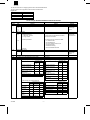
CONTENTS
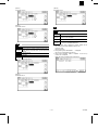
[Note]
This Service Manual describes only the differences from 00ZAR-505//A1E.
The items which are not described in this Manual are common with the
00ZAR505//A1E.
[ 1 ] GENERAL . . . . . . . . . . . . . . . . . . . . . . . . . . . . . . . . . . . . . . . . . . . 1-1
[ 2 ] SPECIFICATIONS. . . . . . . . . . . . . . . . . . . . . . . . . . . . . . . . . . . . . 2-1
[ 3 ] CONSUMABLE PARTS. . . . . . . . . . . . . . . . . . . . . . . . . . . . . . . . . 3-1
[ 4 ] INSTALLATION AND SETUP . . . . . . . . . . . . . . . . . . . . . . . . . . . . 4-1
[ 5 ] EXTERNAL VIEW AND INTERNAL STRUCTURE. . . . . . . . . . . . 5-1
[ 6 ] SETTING AND ADJUSTMENTS. . . . . . . . . . . . . . . . . . . . . . . . . . 6-1
[ 7 ] SIMULATION. . . . . . . . . . . . . . . . . . . . . . . . . . . . . . . . . . . . . . . . . 7-1
[ 8 ] DISASSEMBLY, ASSEMBLY, MAINTENANCE . . . . . . . . . . . . . . 8-1
[ 9 ] TROUBLE CODE LIST . . . . . . . . . . . . . . . . . . . . . . . . . . . . . . . . . 9-1
[10] OPERATIONAL DESCRIPTION . . . . . . . . . . . . . . . . . . . . . . . . . 10-1
This document has been published to be used
for after sales service only.
The contents are subject to change without notice.
AR-287/337
AR-407/507
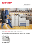
The AR-287/337/407/507 is a slightly upgraded model of the AR-286/336/405/505.
The base models and their upgraded models are listed in the table below.
Upgrade list
Base model
AR-286
AR-336
AR-405
AR-505
Upgraded model
AR-287
AR-337
AR-407
AR-507
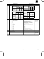
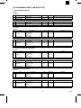
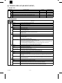
List of changes AR-286/336/405/505 to AR-287/337/407/507
Section
[1]
[2]
AR-286/336/405/505
Page
Content
GENERAL
2. System outline (Options)
1-3
1-6
1-7
1-8
SPECIFICATIONS
2-1
1. Machine type
2-4
13. Additional functions
A. Main body functions
B. Copy function
AR-287/337/407/507
Change
[4]
[5]
[6]
Refer to the
attached page
1-3A/4A.
Memory
Refer to the
attached page
2-7/8/9/10/11/12.
The following six new functions are added.:
21. Tandem function
22. Confidential print
23. Large volume document mode
24. Security function
25. Network Scanning
26. E-mail Status/E-mail Alerts
2-6
[3]
The network scanner kit (AR-NS1) is added.
Communication (E-mail Status/E-mail Alerts)
New functions are added.
15. Other specifications
16. Outlook
CONSUMABLE PARTS
1. Consumable Parts List
3-1
to
3-7
INSTALLATION AND SETUP
EXTERNAL VIEW AND INTERNAL STRUCTURE
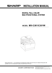
SETTING AND ADJUSTMENTS
6-3
(3) Developing bias voltage adjustment
Change (Lower Heat Roller Kit/Lower Heat Roller)
No change
No change
(3) Developing bias voltage adjustment
Adjustment range
AR-501
Others
/505
Developing negative bias
voltage (Auto)
Developing negative bias
voltage (Character)
Developing negative bias
voltage (Character, Photo)
Developing negative bias
voltage (Photo)
Developing bias (Printer)
Developing positive bias voltage
Adjustment range
AR-287/
AR-507
337/407
Developing negative bias
voltage (Auto)
Developing negative bias
voltage (Character)
Developing negative bias
voltage (Character, Photo)
Developing negative bias
voltage (Photo)
Developing negative bias
voltage (Toner save)
Developing negative bias
voltage (Printer)
Developing positive bias voltage
–425 ±5V –500 ±5V
–500 ±5V –500 ±5V
–500 ±5V –500 ±5V
–500 ±5V –500 ±5V
–500 ±5V –500 ±5V
+150 ±5V +150 ±5V
(4) Main charger grid voltage adjustment
–500 ±5V –425 ±5V
–500 ±5V –500 ±5V
–500 ±5V –500 ±5V
–500 ±5V –500 ±5V
–450 ±5V –500 ±5V
–500 ±5V –500 ±5V
+150 ±5V +150 ±5V
(4) Main charger grid voltage adjustment
Adjustment range
AR-280/ AR-250/281/ AR-501
285/ 335 286/336/405
/505
Grid voltage (Auto) –642 ±5V –602 ±5V –570 ±5V
Grid voltage
–642 ±5V –602 ±5V –645 ±5V
(Character)
Grid voltage
–642 ±5V –602 ±5V –645 ±5V
(Character, Photo)
Grid voltage
–642 ±5V –602 ±5V –645 ±5V
(Photo)
Grid voltage
–642 ±5V –602 ±5V –645 ±5V
(Printer)
Grid voltage (FAX) –642 ±5V –602 ±5V –645 ±5V
3/13/2000
Remark
–1–
Grid voltage (Auto)
Grid voltage (Character)
Grid voltage (Character,
Photo)
Grid voltage (Photo)
Grid voltage (Toner save)
Grid voltage (Printer)
Adjustment range
AR-287/
AR-507
337/407
–602 ±5V –570 ±5V
–602 ±5V –645 ±5V
–602 ±5V
–645 ±5V
–602 ±5V
–552 ±5V
–602 ±5V
–645 ±5V
–645 ±5V
–645 ±5V
Refer to the
attached page
3-8A/9A.
AR-287/337
AR-407/507
Section
[6]
Page
6-5
AR-286/336/405/505
Content
(5) Transfer charger current adjustment
AR-287/337/407/507
Change
(5) Transfer charger current adjustment
Adjustment spec
AR-250/280
AR-501
/281/285/286 AR-405
/505
/335/336
TC drum current
+13.5
+15.0
+18.0
(Front surface mode)
+1.5mA
+1.5mA +1.5mA
TC drum current
+13.5
+15.0
+18.0
(Back surface mode)
+1.5mA
+1.5mA +1.5mA
Transfer charger
current
Transfer charger
current
(6) Separation charger DC component voltage
TC drum current
(Front surface mode)
TC drum current
(Back surface mode)
[7]
[8]
[9]
Adjustment range
AR-287
/337
–140 ±10V
–150 ±10V –200 ±10V
–140 ±10V
–150 ±10V –200 ±10V
SIMULATION
B. List
C. Details of simulations
8-1
8-2
8-6
8-7
22-1
26-10/12/13
26-22
26/32
26-44
26-52
50-1/2
50-26
51-3
61-2/4
67-18
DISASSEMBLY, ASSEMBLY, MAINTENANCE
TROUBLE CODE LIST
Adjustment spec
AR-287
AR-407 AR-507
/337
+13.5 to +15.0 to +18.0 to
+15.0mA +16.5mA +19.5mA
+13.5 to +15.0 to +18.0 to
+15.0mA +16.5mA +19.5mA
(6) Separation charger DC component voltage
Adjustment range
AR-250/280
AR-501
/281/285/286 AR-405
/505
/335/336
Separation DC
component
voltage (Front
surface mode)
Separation DC
component
voltage (Back
surface mode)
Separation DC
component
voltage (Front
surface mode)
Separation DC
component
voltage (Back
surface mode)
OPERATIONAL DESCRIPTION
AR-407
AR-507
–140 ±10V –150 ±10V –200 ±10V
–140 ±10V –150 ±10V –200 ±10V
Change
Change (Delete: TONER SAVE)
Change (Default value: AR-287/337/407)
Change (Default value: AR-287/337/407)
Change (Default value: AR-287/337/407)
Change (Delete: Fax item)
Add
Change (Add: ITALIAN/SWEDISH/DUTCH)
Add
Change
Add
Change
Add
Add (AR-507 Europe and U.K. only)
Change (Default value: AR-287/337/407)
Add
No change
Add (Trouble code: CE)
[10]
Remark
Refer to the
attached page
7-51 – 7-57.
Refer to the
attached page
9-1
No change
–2–
3/13/2000
AR-287/337
AR-407/507
AR-287/337
AR-407/507
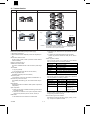
2. System outline (Options) (AR-287/337/AR-407/507)
Copier model
Name
Automatic document feeder
Reversing automatic document feeder
Stand/500 sheet paper drawer
Large capacity tray
500-sheet paper drawer
Desk
2-tray paper exit unit
Exit tray
Dual tray output unit
Finisher
Printer board
NIC card (10 base T/2)
NIC card (10 base T/100 base TX)
Network scanner kit
Mounting kit
Tandem connection cable
Sharpdesk 5 license kit
Security ROM
Model
RSPF
AR-RF1
AR-RF2
AR-DE1N
AR-DE7
AR-LC1N
AR-CS1
AR-CS3
AR-DD1
AR-DU1
AR-TE1
AR-287
—
Standard
—
m
—
m
m
—
m
Standard
m
AR-337
—
Standard
—
m
—
m
m
—
m
Standard
m
AR-407
—
—
Standard
m
—
m
m
—
m
Standard
m
AR-TE2
—
—
—
AR-TR1
AR-FN1N
AR-FN2
AR-FN3
AR-PB2A
AR-SM1
AR-NC1D
AR-NC3D
AR-NS1
AR-XB3
AR-CA1
AR-U11M
AR-U15M
AR-FR1
AR-FR2
AR-FR3
m
m
m
—
m
m
m
m
m
m
—
m
m
m
—
—
m
m
m
—
m
m
m
m
m
m
m
m
m
m
—
—
m
m
m
—
m
m
m
m
m
m
m
m
m
—
m
—
1 – 3A
AR-507
Standard
—
—
—
m
m
—
m
m
Standard
m (SEC/SECL)
m (EX destinations
other than
SEC/SECL)
—
—
—
m
m
m
m
m
m
m
m
m
m
—
—
m
3/13/2000
AR-287/337
AR-407/507
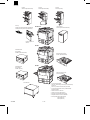
Finisher:
AR-FN1N (AR-287/337/407)
Exit tray:
AR-TE1 (AR-287/337/407/507 (SEC/SECL))
AR-TE2 (AR-507 (Other than SEC/SECL))
Finisher:
AR-FN2 (AR-287/337/407)
AR-287/337
Finisher:
AR-FN3 (AR-507)
Large capacity:
AR-LC1N (AR-287/337/407/507)
Dual tray output unit:
AR-TR1
AR-407
Stand/500 sheet
paper drawer:
AR-DE1N (AR-287/337/407)
500-sheet paper drawer:
AR-CS1 (AR-287/337/407)
AR-507
Stand/500-sheet
paper drawer:
AR-DE7 (AR-507)
500-sheet paper drawer:
AR-CS3 (AR-507)
Desk: AR-DD1
· Printer board: AR-PB2A
· NIC card (10baseT/2) (Provided by local distributors):
AR-NC1D
· NIC card (10 base T/100 base TX): AR-NC3D
· Printer board (Expansion memory 16MB x2 SIM):
AR-SM1 (AR-507)
· Network scanner kit: AR-NS1
· Tandem connection cable AR-CA1
· Mounting kit: AR-XB3 (AR-287/337/407)
· Sharpdesk 5 license kit: AR-U11M/U15M
· Security ROM: AR-FR1 (AR-287/337)
AR-FR2 (AR-407)
AR-FR3 (AR-507)
3/13/2000
1 – 4A
AR-287/337
AR-407/507
15. Other specifications
[2] SPECIFICATIONS
(AR-287/337/407/507)
Photoconductor kind
Photoconductor dia.
Process cleaning
Exposure lamp
Developing system
1. Machine type
Product
CPM
Name
Type
Document
Feeder
Paper
Exit
Memory
RAM
HD
AR-287
28
Duplex
Desk top
RADF
1 tray
32 MB 4.3 GB
AR-337
33
Duplex
Desk top
RADF
1 tray
32 MB 4.3 GB
AR-407
40
Duplex
Desk top
RADF
1 tray
32 MB 4.3 GB
AR-507
50
Duplex
Desk top
RSPF
1 tray
48 MB 4.3 GB
*
Charging system
Transfer system
Separation system
Standard’s spec
13. Additional functions
Fusing system
Fusing cleaning
A. Main body functions
APS
AMS
AMS by flow scan with DF is not allowed.
Auto tray switching
OPC drum
65 f
Blade
No-electrode xenon lamp
Dry, 2-component magnetic brush
development
DC negative scorotron (saw tooth
electrode)
DC positive control
AR-287/337/ AC corotron/DC bias
407
separation pawl
AR-507
Photo discharge/AC corotron
/DC bias separation pawl
Heat roller
AR-287/337/ —
407
AR-507
Yes
16. Outlook
1 scan multi copy
Rotation copy
Pre-heat
Conditions are set with the key operation.
Auto shut off
Conditions are set with the key operation.
W ´ D ´ H (mm)
AR-287/337
AR-407
AR-507
Message display
Key operator program
Communication
E-mail Status/E-mail Alerts
600 ´ 695 ´ 750
600 ´ 700 ´ 750
600 ´ 700 ´ 773
Machine
occupying
dimensions
1292 ´ 695
1292 ´ 700
1292 ´ 700
Weight
Approx 98 kg
Approx 98 kg
Approx 102 kg
Process control
Coin vendor
Only the connector is provided on the
PWB.
B. Copy function
AR-287/337
AR-407
Job call/ registration
Dept. control
Binding margin
Edge erase
AR-507
9
Max. 50 dept.
Max. 500 dept.
(Copy/Print/Tandem)
Shift width AB series: 10mm, Inch series: 1/2"
with adjustment (Binding direction selectable)
AB series: 10mm, Inch series: 1/2" with
adjustment
Center erase
1-set, 2-copy
Independent zooming
White/black reversion
Cover paper
OHP insert paper
25 to 800% for
vertical/horizontal
25 to 400% for
vertical/horizontal
All surface only (only in the manual mode)
Cover/back cover/cover and back cover
Insert paper copy Yes/No
selectable
Only 1 face-up
paper exit is possible
Centering
Multi shot (Nin1)
Repeat copy
Date print
Combination with AMS allowed
Time setting by the key operation.
Stamp function
Middle binding
Page print
Confidential print
Security function
Tandem print (copy/print)
Network scanner
Document scan mode
(Large quantity
document mode)
Security ROM is installed. (AR-FR1/FR2/FR3)
When the tandem connection cable is connected
(AR-287 invalid)
When the scanner expansion kit is installed
Documents of 120 sheets
2–7
3/13/2000
AR-287/337
AR-407/507
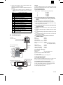
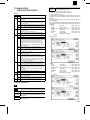
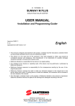
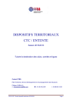
21. Tandem function
AR-505
AR-507/407/337
Model
50
Job
50
50
40
40
33
33
50
Copy
Copy
Client PC
Print
Printer kit
Tandem print
ON/OFF selection
Limitation • System limitation (Mirror configuration)
Two models in tandem connection must be of the same ROM
version and the same option composition.
Relationship between MAIN and SUB:
(Outline)
Enhances the process efficiency of large volume copying.
·
·
Shortens the copying time.
Allows selection between dispersed process and integrated process.
Models with the tandem function:
·
In tandem copy, MAIN and SUB are set with a simulation.
Tandem copy cannot be selected from SUB. (AR-337, AR-407,
AR-507)
When the tandem function is set, MAIN goes into the READY
state even though SUB is in the following conditions.
Number of connections: Max. 2
State of SUB
Installation/connection method:
Paper empty
Serviceman installation/Tandem cable connection (Cable length
4m)
SUB display after starting
Paper supply message
Paper size wrong Paper check message
Cover open
Jobs available:
Cover open message
Copy only (AR-505)
Jam
Jam map display
Copy output/print output (AR-337, AR-407, AR-507)
Pre-heat
After recovery, MAIN and SUB start together.
Toner empty
Toner supply message
Tandem copy operation mode:
Sort/Staple mode (Group cannot be selected.)
Tandem print start condition:
Job division system:
When tandem print data is received, tandem print is performed
even though SUB is in the following conditions.
1/2 auto division (In case of an odd number, the MAIN side is +1.)
Mutual recovery in case of a trouble:
State of SUB
Not available (After dividing a job, each machine finishes its process.)
Paper empty
Basic operation:
After data transmission from MAIN to SUB, operation is performed
independently.
Option composition:
·
When only one finisher is installed, the finishing process cannot
be selected. (AR-505)
·
When there is a difference in the option composition, tandem
copy/print is not performed. (AR-337, AR-407, AR-507) *1
Message displayed
Paper supply message
Paper size wrong
Tandem operation
Paper check message
No suitable paper
size
Tandem operation
Paper set message
Pre-heat
Tandem operation
After recovery of SUB,
the operation is
automatically started.
Tandem operation is performed only when MAIN is in stand-by or
during printing and SUB is in stand-by.
Start of tandem copy from each condition:
The ROM versions of two machines must be identical.
3/13/2000
Operation
Tandem operation
Availability of tandem copy from each condition:
ROM version:
·
Main starts a job. SUB receives the job separated from MAIN.
(AR-505)
Tandem copy start conditions:
AR-505, AR-337, AR-407, AR-507 (Connection between different
models is inhibited.)
·
·
·
When MAIN is in stand-by and SUB is copying, printing, or scanning, all copies are outputted from MAIN.
2–8
AR-287/337
AR-407/507
*1:
"Option" means a finisher, an ADU, a paper feed desk, a largecapacity tray, or a paper feed module.
(Outline)
To protect confidential documents, print is inhibited unless the user
performs the specified operation from the main operation panel after
giving a print command from PC.
(Operations when there is a difference between the option compositions)
1. Tandem copy: The tandem copy key is displayed, but the
conditions to execute the tandem function are not satisfied.
Code: XX
Code
00
Code
10
11
12
13
20
21
22
23
24
30
40
41
50
51
52
53
(1) Accumulated print jobs
Number of jobs
1
2
4
8
16
Tandem operation condition
SCSI communication disable
Tandem mirror condition
Model code disagreement
ICU-ROM version disagreement
PCU-ROM version disagreement
OPE-ROM version disagreement
After-process unit connection disagreement
Paper exit port connection disagreement
ADU connection disagreement
DESK connection disagreement
LCC connection disagreement
ADU trouble information disagreement
Sim26-6: Destination setup disagreement
Sim26-46: Image output direction setup disagreement
Security mode setup disagreement
Duplex copy inhibition setup disagreement
Staple inhibition setup disagreement
Manual tray select inhibition disagreement when
offset tray is selected
(2) The following operations can be performed during
operation of confidential print or during confidential
printing.
·
·
·
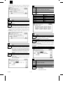
22. Confidential print
Delete of confidential print data (Password entry is required.)
Cancel of confidential print during printing by means of the "C" key.
Invalid during recovery from pre-heat.
·
Changing the environment setup by means of the environment
setup key.
·
Command of continuous output in a different size or from a different tray
·
For confidential printing, paper selection is allowed only in AUTO
selection.
·
For confidential printing, paper insertion, booklet, and OHP index
paper insertion are inhibited.
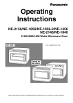
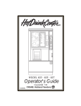
(4) Confidential print output operation is allowed or
inhibited as follows
Client PC
Enter PIN.
In the driver menu.
Ready:
Copy reading:
Copy outputting:
Scanner document scanning:
Scanner data transmission:
Printing:
✱ ✱ ✱ ✱ ✱
After RIP, image data and
PIN are stored.
[1]
[2]
[3]
[4]
[5]
[6]
[7]
[8]
Checking all the lists of the accumulated confidential prints.
(3) The following operations cannot be performed during
confidential printing.
2. Tandem print: All the prints are made by MAIN.
PIN
Number of pages of one job (A4, letter)
320 pages
240 pages
120 pages
60 pages
28 pages
Staple printing:
Tandem copy reading:
Tandem copy outputting:
Tandem print outputting:
Image data
PIN data
HDD
Allowed
Inhibited
Inhibited
Inhibited
Inhibited
Inhibited (Confidential print allowed
when interrupted in offline.)
Inhibited
Inhibited
Inhibited
Inhibited
(5) Conditions of password
Network card
Number of digits:
Characters:
Printer board
5
Only numeric figures 0 to 9
(6) Process in the case of HDD overflow
·
·
·
The job is canceled.
The status monitor makes the error display to PC.
Notice Page output is performed.
(7) Troubles during printing
PIN
When the machine is stopped by paper empty or a paper jam, remove the trouble, and the job will be automatically continued.
✱ ✱ ✱ ✱ ✱
Enter PIN on the operation panel.
(8) Combination with the security function
·
·
·
·
When the security function is ON, confidential print is inhibited.
When confidential data is received, it is automatically canceled.
The status monitor makes the error display to PC.
Notice Page output is performed.
Printout
2–9
3/13/2000
AR-287/337
AR-407/507
(9) Operations when the printer department
management function is set
·
When the key operator program (to record the print quantity to
each department) is ON, the department management function is
valid to confidential print.
·
In this case, when an output command is made from the operation
panel, entry of the department number is not required.
24. Security function
Security function
ON/OFF
ON
OFF
(10) Combination with tandem print
·
HDD
Combination between tandem print and confidential print is not allowed.
HDD
(11) In case of a trouble
·
Data storage
HDD
(12) Data storage
·
·
·
Data storage
When trouble code F9 occurs, the display cannot shift to the confidential menu.
HDD
When an output is completed, data are deleted from the list.
When the printer power is turned off with the confidential print data
remained in the HDD, the confidential print data are deleted completely.
Print output
When the auto power shut off function activates, the confidential
print data are deleted completely.
Print output
HDD
HDD data
clear
READY
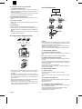
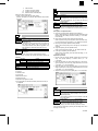
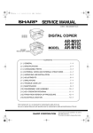
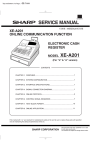
23. Large volume document mode
A
B
50 pages
50 pages
C
READY
20 pages
(Outline)
In the current model, when the following job is entered after completion of output (copy, print) and before deleting the data in the HDD,
the new data is overwritten to the former data.
Therefore, the data can be read by removing the HDD from the machine and the confidentiality is not kept.
Therefore, the data in the HDD is deleted after completion of output.
Document over 50 pages are dividedly read.
∗ Max. 120 pages
A. Security mode operation
(1) Process after completion of output
Every time when an output is completed, the data in the HDD is deleted.
During deleting operation, the other operations is disabled.
(2) Addition of HDD data delete function
Divided documents are integrated
and printed out continuously.
All document data in the HDD can be deleted by operating the operation panel.
To prevent data from being left in the HDD when the main power is
turned off, it is advisable for users who seek a high level of security to
perform this operation.
The key operator can perform this operation.
When this key is pressed, all image data in the HDD including confidential print data is deleted.
A
B
C
A
B
C
A
B
C
A
B
C
·
B. Security mode selection
A large volume of documents, which cannot be fed by the document feeder at one time, is divided and read and copied. (Max.
120 pages)
(1) ON/OFF selection
Key operator program P43 (Selection with the check box)
Initial setup: OFF
·
The sequence of reading documents is from the top bundle of
documents in the normal sequence for the 1 to N machine, and
from the bottom bundle of documents in the reverse sequence for
the N to 1 machine.
·
When copying is performed in this mode, the copy mode cannot be
changed. However, interruption copy is allowed.
Simulation allows to select YES/NO of display of the security mode in
the key operator program.
·
When the large volume mode is set in the SDF mode, the auto
feed function of the SDF mode is disabled and the operations are
made according to the large volume mode.
Shipment setup: OFF
Though the security mode is OFF, the "HDD data delete" key is active.
(2) Simulation countermeasures
C. Combination with confidential print
When the security function (the check box of security mode setup) is
ON, confidential print is inhibited.
When confidential data is received, it is automatically canceled.
The status monitor makes the error display to PC.
Notice Page output is performed.
3/13/2000
2 – 10
AR-287/337
AR-407/507
D. Note for job interruption
Item
e-mail System
Though the security function is ON, if the machine is stopped due to
the following causes, deletion after completion of output and deletion
of HDD data is disabled unless the cause is removed and the job is
completed.
If the machine is left, data is remained in the HDD for a long time. Be
careful of that.
·
·
·
·
Specify the Sender (Setting
"From" field)
Destination Profile Setting
(No. of destinations)
Scan Profile Setting
Paper empty
Paper jam
Toner empty
Interruption copy
Subject & Text
(Mail title and text/Scan to
e-Mail)
E. Combination with tandem copy
· When the security mode check box is ON, tandem copy cannot be
set.
·
When the security mode check box is ON, if tandem print data is
received, all are printed by MAIN.
The network scanner system allows to send files of scanned image
data to each destination through the network.
·
·
·
"Cannot be performed during warm-up.
Execute after completion of warm-up."
The network scanner sends back documents directly to the user’s
desktop. At that time, the desktop application, Sharpdesk is automatically started. Use of Sharpdesk allows view and correction of images,
attachment of notes, edition, save of documents, and conversion into
the PDF type. Furthermore, it allows scanning, printing, transmission
functions (e-mail, FAX), binding of documents, and starting of other
application by using the user interface. It also allows setup of image
correction options.
Item
Scanner expansion kit
Maximum Document Size
A3/WLT
Original Feeding Speed (PPM) 24PPM: AR-287
24PPM: AR-337
27PPM: AR-407
33PPM: AR-507
(8.5" x 11 continuous scanning of same page)
Page order of multipage
1–N
documents
Optical Resolution
400dpi
Output Resolution
200,300,600dpi
Scaling
–
Output Mode
1bit
Halftoning Process
– Error Diffusion
(Dithering Method)
(200/300/600dpi)
– TIFF6.0:CCITT
(G.3/G.4 Single/Multipage
TIFF Uncompressed TIFF)
– PDF
(G.3/G.4)
Yes
Duplex
Network Protocols
Network protocols
(Mail system)
LAN Connectivity
Client Software
Attached file type
File server storage scan: Hyper link is simultaneously transmitted
by e-mail.
b. Desktop distribution scan
A. Specifications
Embedded Web Server
Desktop distributions can
This system scans documents directly for the SMTP e-mail system.
The scanned document is treated as an attached MIME file and distributed to the receiver through the e-mail system.
25. Network Scanning
Web Browser
E-mail distribution scan: As attached TIFF or PDF files
a. E-mail distribution scan
When a service call occurs with the security mode ON, the user
setup key does not work and the HDD data cannot be deleted.
User Interface
(Control Panel)
Client PC
Changeable by the operation panel of the
machine.
Initial setting: 7 languages of the same
contents
E-MAIL title
Title can be entered.
(1) Image file distribution
If the "HDD data delete" key of the key operator program is
pressed during warm-up, the message below is displayed:
Destinations
(Integrations)
About 100
B. Features and functions
F. Deletion of HDD data is not performed in the
following cases
· During warm-up
·
Scanner expansion kit
SMTPcomplying e-mail system
For major mail systems, SLA is under
investigation.
– MS Exchange
– Lotus Notes
– Novell GroupWise
No
c. File server storage scan
Use of this system allows direct scanning of documents for FTP servers.
This system controls transfer by using the user ID, the password, and
the directory information. The user may save the scanned files as one
file or plural files in the filer server. The user may also assign an email address to receive the hyperlink.
(2) Image file generation
This network scanner generates images in some industrial standard
formats. The file type, the resolution, and the mode can be changed.
The following file types are supported.
·
·
– Scan to desktop(FTP)
® Desktop distribution scan
– Scan to file server(FTP)
® File server storage scan
– Scan to e-mail(SMTP)
® E-mail distribution scan
LCD Touch Panel
(400 ´ 256 dots)
Windows95/98/NT
Windows2000
– Internet Explorer4.0 or later
– Netscape Navigator4.0 or later
Yes
(Embedded)
TCP/IP
SMTP
TIFF (Non-compressed, or compressed G3/G4 type)
Image PDF (Compressed G3/G4 type)
C. Additional licenses of Sharpdesk and Network
Scanner
The user may purchase additional licenses of Sharpdesk in the following units:
·
·
1 user
5 users
D. Requirements for composition of the network
system
To use the network scanner, the following components are or configuration is required.
·
·
·
·
·
10Base-T
100Base-TX
Sharpdesk
TIFF, PDF
2 – 11
AR-287/337/407/507
Network scanner expansion kit: AR-NS1
Printer controller: AR-PB2A
NIC: AR-NC3D
Memory: (AR-SM1 x 2)
3/13/2000
AR-287/337
AR-407/507
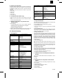
26. E-mail Status/E-mail Alerts
C. Print controller specifications
A. Basic functions
The controllers, AR-PB2A, support the following transmission functions:
(1)
Event driven type text message transmission by using MIB information of AR-PB2A
·
Text mail transmission by event driven setup and schedule driven
setup
(2)
Management information which body has is coded and transmitted in a file type according to the schedule or in the event driven
type. In this case, the specified mail software is used to receive
and develop the data.
·
Mail transmission with an attached file by event driven setup and
schedule driven setup.
However, mail transmission with an attached file stated above is enabled only when the main body complies with generation of information of the attached file. That is, transmission of an attached file can
be made only when the AR-PB2A is installed to the AR-287/
337/407/507.
The above functions are available as standard provision only when
AR-PB2A and the AR-NC3D are installed. For (2), the software key
protect is made.
B. Main body specifications
For E-mail Status / Alerts without an attached file, as follows:
The body provides event information to the controller.
The file generated by the ICU according to setup can be transmitted
as an attached file as information for dealers. When a dealer’s mail
address is set, a file can be attached only to a mail which is transmitted to the mail address.
(1) Additional machine information
Information to identify the machine. The user administrator manually
enters this information by using a browser. The information is displayed in the text of the mail.
*
To read the attached file, the specified mail software is required. That
is, the attached file includes numeral information of each main body
and event information in coded state. If the other mail software is
used to receive, the display contents on the client side cannot be
guaranteed.
These items of information are kept on the controller side or on the
NIC side.
·
·
·
Machine name
Machine code
Installation place
(2) Alert Message
ID
1
Event
Paper Jam
Message
!!! MISFEED HAS OCCURRED !!!
2
Toner Low
!!! TONER SUPPLY IS LOW !!!
3
Toner Empty
!!! ADD TONER !!!
4
Paper Empty
!!! LOAD PAPER / XXX !!!
5
Service Required
!!! CALL FOR SERVICE !!!
6
PM Required
!!! MAINTENANCE REQUIRED !!!
Condition
When paper/document jam has occurred. If a jam is detected when the power is turned ON or reset,
checking is made again.
When toner LOW is detected for the first time. If toner LOW is detected when the power is turned
ON or reset, checking is made again.
When toner empty is detected for the first time. If toner empty is detected when the power is turned
ON or reset, checking is made again.
When paper empty is detected for the first time. If paper empty is detected when the power is turned
ON or reset, checking is made again. No information on the number of steps of trays. Manual feed
is not supported. When a tray empty is detected, information of all the trays that are empty at that
time is delivered.
When the machine enters the self-diagnosis mode. If detected when the power is turned ON or
reset, checking is made again.
When the maintenance counter or the developer counter reaches the specified count. If detected
when the power is turned ON or reset, checking is made again.
(3) Status Message
D. Handling of transmission data
a. Counter information
In E-mail Alerts and E-mail Status, a transmission task is generated
regardless of the job which is under process in the machine. These
tasks are processed in the following rules:
When schedule driven is set, the total counter, the copy counter, and
the printer counter are displayed in a mail address for general. These
information items are supplied from the controller MIB. The "total
counter" means the "effective paper counter" controlled by the ICU.
·
When the machine receives a mail transmission request during a
job process (copy scan, copy output, print output, other process) of
the machine, it performs transmission process regardless of the
job.
·
When the machine receives a mail transmission request under
other situation, if the job is triggered during transmission process,
the job is started.
·
When the machine receives a mail transmission request during the
simulation mode, the request is accepted and transmission process is started.
·
When the machine receives a mail transmission request during the
key operator program, it is accepted and transmission process is
started.
·
When the controller sends two or more requests during a job, only
the last request is accepted.
b. Timer information
For schedule drive message, the controller controls transmission time
by means of the timer of the ICU timer of the machine, and transmits
a mail.
Timer setup is made from the Web setup page.
3/13/2000
2 – 12
AR-287/337
AR-407/507
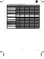
[3] CONSUMABLE PARTS (AR-287/337/407)
1. Consumable Parts List
A. USA
AR-287/337
No.
ITEM
5
Lower Heat Roller Kit
12
Lower Heat Roller
CONTENTS
Lower Heat Roller
Fusing Separation Pawl (lower)
Lower Heat Roller
´1
´2
´1
LIFE
CONTENTS
Lower Heat Roller
Fusing Separation Pawl (lower)
Lower Heat Roller
´1
´2
´1
MODEL NAME
160K
AR-505LH
160K
AR-505HR
LIFE
MODEL NAME
REMARKS
Replacement of fusing separation pawl for every 90
K should be done using those supplied separately.
AR-407
No.
ITEM
5
Lower Heat Roller Kit
12
Lower Heat Roller
180K
AR-505LH
180K
AR-505HR
LIFE
MODEL NAME
160K
AR-337KB
160K
AR-505HR
LIFE
MODEL NAME
180K
AR-337KB
180K
AR-505HR
LIFE
MODEL NAME
160K
AR-337KB
160K
AR-505HR
LIFE
MODEL NAME
180K
AR-407KB
180K
AR-505HR
LIFE
MODEL NAME
160K
AR-337KB
160K
AR-505HR
LIFE
MODEL NAME
180K
AR-407KB
180K
AR-505HR
REMARKS
Replacement of fusing separation pawl for every 90
K should be done using those supplied separately.
B. Canada
AR-287/337
No.
ITEM
5
160K PM Kit
12
Lower Heat Roller
CONTENTS
Upper Heat Roller
Lower Heat Roller
Toner Receiving Seal
DV Seal
Heat Roller Gear
Lower Heat Roller
´1
´1
´1
´1
´1
´1
CONTENTS
Upper Heat Roller
Lower Heat Roller
Toner Receiving Seal
DV Seal
Heat Roller Gear
Lower Heat Roller
´1
´1
´1
´1
´1
´1
REMARKS
AR-407
No.
ITEM
5
180K PM Kit
12
Lower Heat Roller
REMARKS
C. Europe / U.K. / Australia / New Zealand
AR-287/337
No.
ITEM
5
160K PM Kit
12
Lower Heat Roller
CONTENTS
Upper Heat Roller
Lower Heat Roller
Toner Receiving Seal
DV Seal
Heat Roller Gear
Lower Heat Roller
´1
´1
´1
´1
´1
´1
CONTENTS
Upper Heat Roller
Lower Heat Roller
Toner Receiving Seal
DV Seal
Heat Roller Gear
Lower Heat Roller
´1
´1
´1
´1
´1
´1
REMARKS
AR-407
No.
ITEM
5
180K PM Kit
12
Lower Heat Roller
REMARKS
D. Asia / Middle & South America
AR-287/337
No.
ITEM
5
160K PM Kit
12
Lower Heat Roller
CONTENTS
Upper Heat Roller
Lower Heat Roller
Toner Receiving Seal
DV Seal
Heat Roller Gear
Lower Heat Roller
´1
´1
´1
´1
´1
´1
CONTENTS
Upper Heat Roller
Lower Heat Roller
Toner Receiving Seal
DV Seal
Heat Roller Gear
Lower Heat Roller
´1
´1
´1
´1
´1
´1
REMARKS
AR-407
No.
ITEM
5
180K PM Kit (200V)
12
Lower Heat Roller
3 – 8A
REMARKS
3/13/2000
AR-287/337
AR-407/507
E. Middle East / Africa
AR-287/337
No.
ITEM
5
160K PM Kit
12
Lower Heat Roller
CONTENTS
Upper Heat Roller
Lower Heat Roller
Toner Receiving Seal
DV Seal
Heat Roller Gear
Lower Heat Roller
´1
´1
´1
´1
´1
´1
CONTENTS
Upper Heat Roller
Lower Heat Roller
Toner Receiving Seal
DV Seal
Heat Roller Gear
Lower Heat Roller
´1
´1
´1
´1
´1
´1
LIFE
MODEL NAME
160K
AR-337KB
160K
AR-505HR
LIFE
MODEL NAME
180K
AR-407KB
180K
AR-505HR
REMARKS
AR-407
No.
ITEM
5
180K PM Kit
12
Lower Heat Roller
3/13/2000
3 – 9A
REMARKS
AR-287/337
AR-407/507
[7] SIMULATION
(AR-287/337/AR-407/507)
Operation/
Procedure
1. Select the print mode with [] key and [¯] key.
2. Enter the adjustment value with the 10-key pad.
B. List
3. Press the [EXECUTE] key.
Code
Main Sub
8
1
2
6
7
22
1
6
26
10
12
13
22
32
44
52
50
1
2
51
26
3
61
2
4
67
(The developing bias output voltage of each print mode
can be adjusted and checked.)
18
The [EXECUTE] key is highlighted, the adjustment value entered in
procedure 2 is set, and the voltage corresponding to the set value is
supplied.
After supplying the voltage for 30 sec, the [EXECUTE] key returns to
the normal display.
If the [EXECUTE] key is pressed while the voltage is supplied, the
voltage output is stopped and the [EXECUTE] key returns to the normal display.
AUTO
: Auto mode
* (500) (–500V ±5V)
CHARA
: Character mode
* (500) (–500V ±5V)
CHARA PHOTO : Character/Photo mode
* (500) (–500V ±5V)
PHOTO
: Photo mode
* (500) (–500V ±5V)
PRINTER
: Printer mode
* (500) (–500V ±5V)
PLUS
: Cleaning mode
* (150) (+150V ±5V)
Developing bias voltage
* ( ): Default
Function (Purpose)
Used to check and adjust the operation of the developing bias
voltage in each print mode and the control circuit. (for OPC
drum type B)
Used to check and adjust the operation of the main charger
grid voltage in each print mode and the control circuit. (for
OPC drum type B)
Used to check and adjust the transfer charger current and the
control circuit.
Used to check and adjust the operation of the separation
charger voltage and its control circuit.
Used to check the print out count of each section in each
operation mode.
(Used to check the maintenance timing.)
Used to output the list of the setting and adjustment data
(simulations, counters).
Used to allow entry of the software key input for the network
scanner.
Used to enter the Diagnosis function key input.
After completion of copier job in copier interruption during a
printer job, the print job is resumed in synchronization with the
auto clear timer (key operation) setup time [10-240]. By
making the setup below, the print job is resumed in 0 sec.
(However, the auto clear function is enabled with the setup
time of key operation. Also, this simulation and auto clear are
not synchronized.)
Used to set the specification (language display) for the
destination. (Excluding the Japan models.)
When the variable speed fan motor is in the ready state and
the process temperature is in the range of 36° – 45°, the
PWM duty is set in percentage.
Used to set the model of the unit which is connected to the
SCSI I/F of ICU PWB.
Used to set whether white paper discharge count up is
performed or not.
("White paper" means insertion paper in the OHP insertion
paper mode (without copy), cover paper in the cover paper
insertion mode (without copy)/back cover, and white paper in
the duplex exit mode (CA etc.).)
Used to adjust the copy image position and the void area
(image loss) on the print paper in the copy mode. (The same
adjustment can be made with SIM 50-2 (simple method).)
Used to adjust the copy image position and the void area
(image loss) on the print paper in the copy mode. (Simple
adjustment)
(This simulation allows the same simulation with SIM 50-1
more simply. )
Used to set the folding margin of center binding.
Used to set the clutch OFF time. (AR-507 Europe and U.K.
only)
Used to adjust the scanner (exposure) laser power (absolute
value) in the copy mode.
Used to adjust the scanner (exposure) laser power (absolute
value) in the printer mode. (For Photoconductor type B)
Used to clear the application data area of the Network
Scanner of the Flash ROM.
(AR-287/337/407)
(AR-507)
AUTO
CHARA
CHARA PHOTO
PHOTO
PRINTER
PLUS
*(
: Auto mode
: Character mode
: Character/Photo mode
: Photo mode
: Printer mode
: Cleaning mode
Developing bias voltage
* (415) (–425V ±5V)
* (490) (–500V ±5V)
* (490) (–500V ±5V)
* (490) (–500V ±5V)
* (490) (–500V ±5V)
* (165) (+150V ±5V)
): Default
C. Details of simulations
8
8 -1
Purpose
Adjustment/Operation test/check
Function
(Purpose)
Used to check the operation of the developing bias voltage in each print mode and its control circuit. (For OPC
drum type B)
Process (OPC drum, developing unit, transfer,
cleaning) section
Section
7 – 51
3/13/2000
AR-287/337
AR-407/507
8 -2
Purpose
Adjustment/Operation test/check
Function
(Purpose)
Used to check and adjust the operation of the main
charger grid voltage in each print mode and the control
circuit. (for OPC drum type B)
Image process (Photoconductor/Developing/Transfer/
Cleaning)
(The charging/grid output voltage in each print mode
can be adjusted and checked.)
Section
Operation/
Procedure
8 -6
1. Select the print mode with [] key and [¯]key.
2. Enter the adjustment value with the 10-key pad.
3. Press the [EXECUTE] key.
The [EXECUTE] key is highlighted, the adjustment value entered in
procedure 2 is set, and the voltage corresponding to the set value is
supplied.
Purpose
Adjustment/Operation test/check
Function
(Purpose)
Used to check and adjust the transfer charger current
and the control circuit.
Section
Copy
Image process
(Photoconductor/
Developing/Transfer/
Cleaning)
The transfer charger output voltage in printing the front
and the back of paper can be adjusted and checked.
After supplying the voltage for 30 sec, the [EXECUTE] key returns to
the normal display.
If the [EXECUTE] key is pressed while the voltage is supplied, the
voltage output is stopped and the [EXECUTE] key returns to the normal display.
(AR-287/337/407)
AUTO
CHARA
CHARA PHOTO
PHOTO
PRINTER
* ( ): Default
Operation/
Procedure
1. Select the print mode with [] key and [¯] key.
: Auto mode
: Character mode
: Character/Photo mode
: Photo mode
: Printer mode
* (602) (–603 ±5V)
* (602) (–603 ±5V)
* (602) (–603 ±5V)
* (602) (–603 ±5V)
* (602) (–603 ±5V)
2. Enter the adjustment value with the 10-key pad.
3. Press the [EXECUTE] key.
The [EXECUTE] key is highlighted, the adjustment value entered in
procedure 2 is set, and the voltage corresponding to the set value is
supplied.
After supplying the voltage for 30 sec, the [EXECUTE] key returns to
the normal display.
If the [EXECUTE] key is pressed while the voltage is supplied, the
voltage output is stopped and the [EXECUTE] key returns to the normal display.
FROMT MODE: Front surface print (with the paper feed tray and
manual paper feed tray)
BACK MODE: Back surface print (with duplex paper feed)
(AR-287/337)
(AR-407)
(AR-507)
AUTO
CHARA
CHARA PHOTO
PHOTO
PRINTER
* ( ): Default
: Auto mode
: Character mode
: Character/Photo mode
: Photo mode
: Printer mode
* (560) (–570 ±5V)
* (635) (–645 ±5V)
* (635) (–645 ±5V)
* (635) (–645 ±5V)
* (635) (–645 ±5V)
(AR-507)
3/13/2000
7 – 52
AR-287/337
AR-407/507
8 -7
Item
Purpose
Adjustment/Operation test/check
Function
(Purpose)
Used to check and adjust the operation of the separation charger voltage and its control circuit.
Section
Others
Image process
(Photoconductor/
Developing/Transfer/
Cleaning)
The separation charger output voltage in printing the
front and the back of paper can be adjusted and
checked.
Operation/
Procedure
Counter
Operation/
Procedure
nnnnnnnn : Counter value
1. Select the print mode with [] key and [¯] key.
2. Enter the adjustment value with the 10-key pad.
22 - 6
3. Press the [EXECUTE] key.
Purpose
Operation data output/Check (Display/Print)
The [EXECUTE] key is highlighted, the adjustment value entered in
procedure 2 is set, and the voltage corresponding to the set value is
supplied.
Function
(Purpose)
Used to output the list of the setting and adjustment
data (simulations, counters).
Item
Data
Operation/
Procedure
When installing or servicing, execute this simulation to
print and store the adjustment values and setting data
for use in the next servicing. (Memory trouble, PWB replacement, etc.)
After supplying the voltage for 30 sec, the [EXECUTE] key returns to
the normal display.
If the [EXECUTE] key is pressed while the voltage is supplied, the
voltage output is stopped and the [EXECUTE] key returns to the normal display.
Adjust/Setting data
In this case, the print conditions can be set optionally.
FROMT MODE: Front surface print (with the paper feed tray and
manual paper feed tray)
BACK MODE: Back surface print (with duplex paper feed)
1. Select the setup item.
(The selected item is highlighted.)
(AR-287/337)
2. Set the item and conditions with the 10-key pad.
3. Press the [EXECUTE] key to print various data.
A: Paper feed mode
1: Manual paper feed
2: Upper paper feed tray
3: Lower paper feed tray
4: Desk upper paper feed tray
5: Desk middle paper feed tray
6: Desk lower paper feed tray
7: Large capacity paper feed tray
(AR-407)
(AR-507)
26
26 - 10
22
Purpose
Setting
Function
(Purpose)
Used to allow entry of the software key input for the
network scanner.
Item
Operation
Operation/
Procedure
1. After entering the sub code of the simulation, enter
the software key in the obtained frame of "NEW."
2. When the obtained number is entered with the 10-key (max. 9 digits), the entered number is displayed in the frame of "NEW." After
entering the number, press the [OK] key, and the entered number
is stored.
22 - 1
Purpose
Operation data output/Check (Display/Print)
3. Reset with the CA key, and the scanner function is enabled.
Function
(Purpose)
Used to check the print out count of each section in
each operation mode.
(Used to check the maintenance timing.)
4. Special note
* Only when SCSI (20 channels/NS1) setup is completed.
If the scanner key input is made without setup, it is rejected.
7 – 53
3/13/2000
AR-287/337
AR-407/507
When the SCSI channel is set to "20," if a software key which
does not correspond to the setup is entered, the setup of "20" is
changed to "1."
26 - 22
Purpose
Setting
Function
(Purpose)
Used to set the specification (language display) for the
destination. (Excluding the Japan models.)
Item
Specifications
Operation/
Procedure
Select the language to be used according to the table
below.
Display
ENG.(US)
ENG.(UK)
FRENCH
SPANISH
GERMAN
ITALIAN
SWEDISH
DUTCH
26 - 12
Purpose
Setting
Function
(Purpose)
Used to enter the Diagnosis function key input.
Item
Operation
Operation/
Procedure
1. After entering the sub code of the simulation, enter
the software key in the obtained frame of "NEW."
Language
English(US)
English(UK)
French
Spanish
German
Italian
Swedish
Dutch
2. When the obtained number is entered with the 10-key (max. 9 digits), the entered number is displayed in the frame of "NEW." After
entering the number, press the [OK] key, and the entered number
is stored.
3. The Alert/Status E-Mail send function with attached data of the
Remote E-Mail Diagnosis System is enabled.
26 - 32
Purpose
Setting
Function
(Purpose)
When the variable speed fan motor is in the ready state
and the process temperature is in the range of 36° –
45°, the PWM duty is set in percentage.
Operation
Item
Operation/
Procedure
26 - 13
Purpose
Setting
Function
(Purpose)
After completion of copier job in copier interruption during a printer job, the print job is resumed in synchronization with the auto clear timer (key operation) setup
time [10-240]. By making the setup below, the print job
is resumed in 0 sec. (However, the auto clear function
is enabled with the setup time of key operation. Also,
this simulation and auto clear are not synchronized.)
Operation
Item
Operation/
Procedure
When this simulation is executed, the current set value
is displayed. At that time, select the fan motor with []
key and [¯] key. Then the set value can be changed
with the 10-key.
When [] key or [¯] key is pressed, the current set value is stored in
the EEPROM.
VFM1&2&4
Adjustment range of 50 – 100% in 1% increment
PCFM VFM5&6 Adjustment range of 50 – 100% in 1% increment
When this simulation is executed, the current set value
is displayed. At that time, the set value can be changed
with the 10-key.
When the [OK] key is pressed, the current set value is
stored in the EEPROM.
26 - 44
3/13/2000
7 – 54
Purpose
Setting
Function
(Purpose)
Used to set the model of the unit which is connected to
the SCSI I/F of ICU PWB.
Section
ICU
Item
Specifications
Operation/
Procedure
A is at the left of B when viewed from the rear side.
0:
1:
3:
Interface/Communication
No connection
Printer controller
External printer controller
AR-287/337
AR-407/507
4:
8:
10:
20:
AXIS controller
Tandem connection (Initiator)
Tandem connection (Target)
Network scanner controller (NS1)
50
50 - 1
Either of the above values is set.
* AR-287 is not provided with the tandem setting.
However, the display is not changed. When tandem setup is tried, it
is rejected.
Purpose
Adjustment
Function
(Purpose)
Used to adjust the copy image position and the void
area (image loss) on the print paper in the copy mode.
(The same adjustment can be made with SIM 50-2
(simple method).)
Picture quality
Image position
Item
Operation/
Procedure
1. Select the adjustment item with [], [¯] keys.
2. Enter the adjustment value with the 10-key.
3. Press the [OK] key. (The adjustment value entered in procedure 2
is set.)
Descriptions on adjustment items
A. Document scan start position adjustment value (RRC-A)
Used to adjust the timing of outputting the image lead edge signal
(SCAN signal) after starting document scanning. (0 – 99: Reference value 50)
26 - 52
Purpose
Setting
Function
(Purpose)
Item
Used to set whether white paper discharge count up is
performed or not.
("White paper" means insertion paper in the OHP insertion paper mode (without copy), cover paper in the
cover paper insertion mode (without copy)/back cover,
and white paper in the duplex exit mode (CA etc.).)
Operation
Operation/
Procedure
When this simulation is executed, the current set value
is displayed.
B. Resist roller clutch OFF timing adjustment value (RRC-B)
Used to adjust the timing of turning ON the resist roller after reception of the resist signal (LD_START). (0 – 99: Reference value 50)
C. Rear edge void quantity adjustment value (DEN-B)
Used to set the void quantity on the rear edge. (0- 99: Reference
value 30)
D. Image loss quantity set value (IMAGE LOSS)
Used to set the image loss quantity. (0 – 99: reference value 20)
E. Lead edge void quantity set value (DEN-A)
Used to set the void quantity on the document lead edge. (0 – 99:
Reference value 20)
Under this state, the set value can be changed with the 10-key.
When the OK key is pressed, the currently set value is stored in the
EEPROM.
A
Set value
0
1
Destination
Japan/Australia
Others
Adjustment procedure
1. Set the image loss quantity (IMAGE LOSS) and the paper lead
edge void quantity (DEN-A) to desired values. (0 – 99:
0.1mm/step)
Content
White paper count up is not performed.
White paper count up is performed.
2. Adjust the document scan start position (RRC_A) so that the image loss quantity of an actual copy image becomes the set value
of procedure 1. (0 – 99: 0.29mm/step)
Default
0 (Count up is not performed.)
1 (Count up is performed.)
3. Adjust the resist roller clutch ON timing (RRC_B) so that the lead
edge void quantity of an actual copy image becomes the set value
of procedure 1. (0 – 99: 0.24mm/step)
When set to 0 (count up is nor performed), the following counters do
not count up.
·
·
·
·
·
·
4. Adjust the rear edge void quantity (DEN_B). (0 – 99: 0.1mm/step)
COPIES counter
Total counter
Maintenance counter
Developer counter
Department management counter
The signal (PNC) for the external auditor (mechanism counter) is
not outputted.
50 - 2
Purpose
Adjustment
Function
(Purpose)
Used to adjust the copy image position and the void
area (image loss) on the print paper in the copy mode.
Item
(Simple adjustment)
(This simulation allows the same simulation with SIM
50-1 more simply. )
Picture quality
Image position
Operation/
Procedure
1. Select the adjustment item with [], [¯] keys.
2. Enter the adjustment value with the 10-key.
3. Press the [OK] key. (The value entered in procedure 2 is set.)
Used to adjust the lead edge by entering the lead edge shift on each
lead edge of 400% copy.
7 – 55
3/13/2000
AR-287/337
AR-407/507
Descriptions on adjustment items
(AR-507)
A. Distance from the image lead edge to 10mm of the scale (Platen
400%) (L1)
B. Distance from the paper lead edge to the image lead edge (L2)
C. IMAGE LOSS
D. DEN-A
E. DEN-B
Adjustment procedures
1. Set the image loss quantity (IMAGE LOSS) and the paper lead
edge void quantity (DEN-A) to desired values. (0 – 99:
0.1mm/step)
51
2. Set L1/L2 to 0.
3. Make a 400% copy with OC, and enter the shift quantity to L1/L2.
(0 – 999: 0.1mm/step)
51 - 3
4. Repeat procedure 3 so that the paper lead edge void quantity of
the actual copy image becomes the set value of procedure 1.
5. Adjust the rear edge void quantity (DEN_B). (0 – 99: 0.1mm/step)
Purpose
Setting
Function
(Purpose)
Used to set the clutch OFF time. (AR-507 Europe and
U.K. only)
Item
Operation
Operation/
Procedure
When this simulation is executed, the current set value
is displayed.
At that time, the set value can be changed with [] key and [¯] key.
When [], [¯], and [OK] keys are pressed, the current set value is
stored in the EEPROM.
Destination
TRC2
TRC1H
Default
Europe
80
U.K.
80
Europe
60
U.K.
60
(Europe/U.K.)
50 - 26
Function
(Purpose)
Used to set the folding margin of center binding.
Operation/
Procedure
When this simulation is executed, the current set value
is displayed.
Under this state, the set value can be changed with the
10-key.
When the OK key is pressed, the currently set value is
stored in the EEPROM.
61
61 - 2
(1 step: 0.1mm)
Item
A
B
C
D
Content
Clear quantity of the folding section of center
binding left image (when the OC is used)
Clear quantity of the folding section of center
binding right image (when the OC is used)
Clear quantity of the folding section of center
binding left image (when the RSPF is used)
Clear quantity of the folding section of center
binding right image (when the RSPF is used)
Range Default
Purpose
Adjustment
0 ~ 99
20
Function
(Purpose)
Used to adjust the scanner (exposure) laser power (absolute value) in the copy mode.
0 ~ 99
30
Section
Laser (Exposure)
0 ~ 99
0
Item
Operation
0 ~ 99
0
Operation/
Procedure
(AR-287/337)
(AR-287/337/407)
3/13/2000
7 – 56
All must be set to "8."
AR-287/337
AR-407/507
(AR-507)
Set default value 5.
(AR-407)
All must be set to "6".
(AR-507)
All must be set to "5."
67
67 - 18
61 - 4
Purpose
Adjustment
Function
(Purpose)
Section
Used to adjust the scanner (exposure) laser power (absolute value) in the printer mode. (For Photoconductor
type B)
Laser (Exposure)
Item
Operation
Operation/
Procedure
(AR-287/337)
Purpose
Data clear
Function
(Purpose)
Used to clear the application data area of the Network
Scanner of the Flash ROM.
Item
Memory
Operation/
Procedure
1. To clear data, press the [EXECUTE] key.
Clear area: 0x8f060000/0x8f07ffff
2. The confirmation menu is displayed to confirm whether the ARNS1 area data in the Flash ROM are cleared or not.
[YES] key: Clear
[NO] key: Not clear
3. During clearing data, "NOW DOING . . ." is displayed.
[No key entry is accepted during clearing.]
4. After normal completion, "END" is outputted. In case of any
trouble, "NG" is outputted.
[When the CA key is pressed, reset is performed.]
Set default value 8.
(AR-407)
Set default value 6.
7 – 57
3/13/2000
AR-287/337
AR-407/507
AR-287/337
AR-407/507
AR-287/337
AR-407/507
[9] TROUBLE CODE LIST (AR-287/337/407/507)
1. Trouble code
Trouble code
CE
Content of trouble
Remark
Trouble detection
00
The other communication error has occurred.
Network
01
The print server card (AR-NC3D) is not installed or defective.
Network
02
The specified mail server or the FTP server is not found.
Network
03
The specified server does not correspond during image transmission.
Network
04
The entered account name of the FTP server or the password is invalid.
Network
05
The entered directory of the FTP server is invalid.
Network
2. Self diagnostics
Trouble code
MAIN
SUB
CE
00
01
02
03
04
05
3/13/2000
Description
Content
The other communication error has occurred.
Detail
Communication error
Cause
Network Cable connection failure
Check and remedy
1) Check that the Network Cable is properly inserted.
Content
The print server card (AR-NC3D) is not installed or defective.
Detail
NC3D connection failure
Cause
NC-3D is not installed to the AR-PB2A board.
NC-3D control PWB trouble
Check and remedy
1) Check that the NC-3D is installed to the AR-PB2A board.
2) Output the NIC Config. Page to check the NIC version.
3) Replace the NIC.
Content
The specified mail server or the FTP server is not found.
Detail
The specified mail server or the FTP server is not found.
Cause
Network Cable connection failure
Network setup failure
SMTP server/FTP server/NST trouble
Check and remedy
1) Check that the Network Cable is inserted properly.
2) Check that the connected network supports TCP/IP protocol.
3) Check from the Web Page that the Primary/Secondary E-mail Server Address or the Destination FTP
server/Desktop PC address are properly set.
4) If the above address is described with Hostname, check that the DNS server is properly set.
5) Check that the SMTP server/FTP server/NST causes a trouble or not.
Content
The specified server does not correspond during image transmission.
Detail
The specified server does not correspond during image transmission.
Cause
Network Cable connection failure
SMTP server/FTP server/NST trouble
Check and remedy
1) Check that the Network Cable is inserted properly.
2) Check that the SMTP server/FTP server/NST causes a trouble or not.
Content
The entered account name of the FTP server or the password is invalid.
Detail
The entered account name of the FTP server or the password is invalid.
Cause
Network Cable connection failure
The account name of the FTP server recorded as the destination or the password for the account name
is erroneous.
Check and remedy
1) Check that the Network Cable is inserted properly.
2) Check that the account name of the FTP server recorded as the destination and the password for the
account name are proper.
Content
The entered directory of the FTP server is invalid.
Detail
The entered directory of the FTP server is invalid.
Cause
Network Cable connection failure
Check that the directory name exists in the FTP server recorded as the destination.
Check and remedy
1) Check that the Network Cable is inserted properly.
2) Check that the directory name exists in the FTP server recorded as the destination.
9 – 1A
AR-287/337
AR-407/507
CAUTION FOR BATTERY REPLACEMENT
(Danish)
ADVARSEL !
Lithiumbatteri – Eksplosionsfare ved fejlagtig håndtering.
Udskiftning må kun ske med batteri
af samme fabrikat og type.
Levér det brugte batteri tilbage til leverandoren.
(English)
Caution !
Danger of explosion if battery is incorrectly replaced.
Replace only with the same or equivalent type
recommended by the manufacturer.
Dispose of used batteries according to manufacturer’s instructions.
(Finnish)
VAROITUS
Paristo voi räjähtää, jos se on virheellisesti asennettu.
Vaihda paristo ainoastaan laitevalmistajan suosittelemaan
tyyppiin. Hävitä käytetty paristo valmistajan ohjeiden
mukaisesti.
(French)
ATTENTION
Il y a danger d’explosion s’ il y a remplacement incorrect
de la batterie. Remplacer uniquement avec une batterie du
même type ou d’un type équivalent recommandé par
le constructeur.
Mettre au rebut les batteries usagées conformément aux
instructions du fabricant.
(Swedish)
VARNING
Explosionsfara vid felaktigt batteribyte.
Använd samma batterityp eller en ekvivalent
typ som rekommenderas av apparattillverkaren.
Kassera använt batteri enligt fabrikantens
instruktion.
AR-287/337
AR-407/507
All rights reserved.
Printed in Japan.
No part of this publication may be reproduced,
stored in a retrieval system, or transmitted,
in any form or by any means,
electronic; mechanical; photocopying; recording or otherwise
without prior written permission of the publisher.
SHARP CORPORATION
Digital Document Systems Group
Quality & Reliability Control Center
Yamatokoriyama, Nara 639-1186, Japan
2000 March