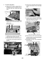
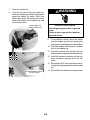
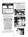
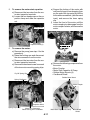
1
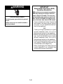
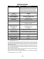
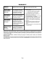
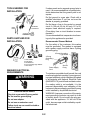
CONSUMER SERVICES TECHNICAL
EDUCATION GROUP PRESENTS
CL-9
HIGH EFFICIENCY
TOP LOAD
COMMERCIAL
WASHER
Model CAW2762K
JOB AID
Part No. 8178129
FORWARD
This Whirlpool Job Aid, “High Efficiency Top Load Commercial Washer,” (Part No. 8178129 ),
provides the technician with information on the installation, operation, and service of the High
Efficiency Top Load Commercial Washer. It is to be used as a training Job Aid and Service Manual.
For specific information on the model being serviced, refer to the “Tech Sheet” provided with the
washer.
The Wiring Diagram is typical and should be used for training purposes only. Always use the Wiring
Diagram supplied with the product when servicing the unit.
GOALS AND OBJECTIVES
The goal of this Job Aid is to provide detailed information that will enable the service technician to
properly diagnose malfunctions and repair the Whirlpool High Efficiency Top Load Commercial
Washer.
The objectives of this Job Aid are to:
• Understand and follow proper safety precautions.
• Successfully troubleshoot and diagnose malfunctions.
• Successfully perform necessary repairs.
• Successfully return the washer to its proper operational status.
WHIRLPOOL CORPORATION assumes no responsibility for any repairs made
on our products by anyone other than Authorized Service Technicians.
Copyright © 2002, Whirlpool Corporation, Benton Harbor, MI 49022
- ii -
TABLE OF CONTENTS
Page
GENERAL............................................................................................................................................. 1-1
Safety First ...................................................................................................................................... 1-1
Model & Serial Number Designations ............................................................................................. 1-3
Model & Serial Number Label And Literature Pack Locations ........................................................ 1-4
Specifications .................................................................................................................................. 1-5
Warranty .......................................................................................................................................... 1-6
INSTALLATION INFORMATION ......................................................................................................... 2-1
Washer Installation Instructions ...................................................................................................... 2-1
THEORY OF OPERATION ................................................................................................................... 3-1
COMPONENT ACCESS ....................................................................................................................... 4-1
Component Locations ..................................................................................................................... 4-1
Removing The Console Components ............................................................................................. 4-2
Removing The Meter Case Assembly Components ....................................................................... 4-5
Removing The Hidden Lid Switch ................................................................................................... 4-8
Removing The Pump, Motor Start Capacitor, & Motor ................................................................. 4-10
Removing The Agitator & Transmission ....................................................................................... 4-12
Removing The Cabinet Assembly ................................................................................................. 4-15
Removing The Dual Vacuum Break .............................................................................................. 4-17
Removing The Tub Ring, Basket, Outer Tub, And Basket Drive Assembly ................................. 4-18
Removing The Suspension System & Base Assembly ................................................................ 4-22
Removing The Rear Panel High Efficiency Components ............................................................. 4-23
COMPONENT TESTING ...................................................................................................................... 5-1
Diverter Valve .................................................................................................................................. 5-1
Motor ............................................................................................................................................... 5-2
Motor Thermal Protector ................................................................................................................. 5-3
Thermistor ....................................................................................................................................... 5-4
Hidden Lid Switch ........................................................................................................................... 5-5
Motor Start Capacitor ...................................................................................................................... 5-5
Pressure Switch .............................................................................................................................. 5-6
Cycle Selector Switch Assembly ..................................................................................................... 5-7
Timer Motor ..................................................................................................................................... 5-7
Basket Drive Shaft Checks ............................................................................................................. 5-8
Automatic Temperature Control ...................................................................................................... 5-9
DIAGNOSIS AND TROUBLESHOOTING ........................................................................................... 6-1
Cycle Chart ..................................................................................................................................... 6-1
Agitation Cycle Switch Closures ..................................................................................................... 6-2
Sequence Chart .............................................................................................................................. 6-2
Bussing Diagram ............................................................................................................................. 6-3
Timer Label ..................................................................................................................................... 6-3
Connectors ...................................................................................................................................... 6-4
WIRING DIAGRAM .............................................................................................................................. 7-1
- iii -
— NOTES —
- iv -
GENERAL
SAFETY FIRST
Your safety and the safety of others is very important.
We have provided many important safety messages in this Job Aid and on the appliance.
Always read and obey all safety messages.
This is the safety alert symbol.
This symbol alerts you to hazards that can kill or hurt you and others.
All safety messages will follow the safety alert symbol and either the word
“DANGER” or “WARNING.” These words mean:
DANGER
You can be killed or seriously injured if you don’t
immediately follow instructions.
WARNING
You can be killed or seriously injured if you don’t
follow instructions.
All safety messages will tell you what the potential hazard is, tell you how to reduce the
chance of injury, and tell you what can happen if the instructions are not followed.
WARNING
WARNING
Electrical Shock Hazard
Disconnect power before servicing.
Replace all parts and panels before
operating.
Failure to do so can result in death or
electrical shock.
Electrical Shock Hazard
Plug into a grounded 3-prong outlet.
Do not remove ground prong.
Do not use an adapter.
Do not use an extension cord.
Failure to follow these instructions can
result in death, fire, or electrical shock.
WARNING
Excessive Weight Hazard
Use two or more people to move and
install washer.
Failure to do so can result in back or
other injury.
1-1
WARNING
IMPORTANT
Electrostatic Discharge (ESD)
Sensitive Electronics
ESD problems are present everywhere.
ESD may damage or weaken the electronic control assembly. The new control assembly may appear to work well
after repair is finished, but failure may
occur at a later date due to ESD stress.
• Use an antistatic wrist strap. Connect the
wrist strap to the green ground connection point, or to an unpainted metal surface in the appliance.
- OR -
Electrical Shock Hazard
Connect green ground wire to ground
screw.
Failure to do so can result in death or
electrical shock.
• Touch your finger repeatedly to a green
ground connection point, or to an unpainted metal surface in the appliance.
• Before removing the part from its package, touch the antistatic bag to a green
ground connection point, or to an unpainted metal surface in the appliance.
• Avoid touching electronic parts, or terminal contacts. Handle the electronic control assembly by the edges only.
• When repackaging the failed electronic
control assembly in an antistatic bag,
observe the previous instructions.
1-2
MODEL & SERIAL NUMBER DESIGNATIONS
MODEL NUMBER
MODEL NUMBER
Y
INTERNATIONAL SALES INDICATOR OR MARKETING CHANNEL
Y = Canada
G = Government On Premise
PRODUCT GROUP
C = Commercial Laundry
PRODUCT IDENTIFICATION
A= Automatic Washer
E = Electric Dryer
G = Gas Dryer
S = Stack Dryer
CONTROL CODE
E = Electronic Control
M = Electromechanical
P = Pushbutton Single Unit or Stacked Pair
W = High Efficiency Top Load
FEATURE CODE
Cabinet Width In Inches (29″ or 27″)
FEATURE / VARIATIONS
4 = Meter Case or Coinslide Equipped Stack W/O Windows
5 = Meter Case and Coinslide Equipped
6 = Meter Case or Coinslide Equipped Stack With Windows
7 = Card Reader Ready / Equipped Stacked Pair
9 = Full Width Console
FEATURE CODE
0 = Electric
1 = Single Speed or Gas
2 = Two Speed
YEAR OF INTRODUCTION
J = 2000, K = 2001
COLOR CODE
Q = White
ENGINEERING REVISION NUMBER
0 = Basic, 1 = 1st Revision, 2 = 2nd Revision
SERIAL NUMBER
SERIAL NUMBER
C
MANUFACTURING SITE
C = Clyde, OH
YEAR OF PRODUCTION
L = 2001, M = 2002
WEEK OF PRODUCTION
PRODUCT SEQUENCE NUMBER
L
16 0 2 2 8 7
1-3
C
A
W 27 6
2
K
Q
0
MODEL & SERIAL NUMBER LABEL
AND LITERATURE PACK LOCATIONS
The Model & Serial Number label location is shown below. A Literature Pack (not shown) is
located behind the front access panel. The pack includes a wiring diagram, parts list, and tech
sheet.
Model & Serial
Number Label Location
12345678
12345678
12345678
LITERATURE PACK
(LOCATED BEHIND THE
FRONT ACCESS PANEL )
1-4
SPECIFICATIONS
MODEL NUMBER
CAW2762KQ0
GENERAL INFORMATION
Stainless steel look console, hidden lid switch, porcelain
finish top and lid, galvanized, extra thick front panel,
galvanized side panels, improved meter case that
accepts larger coin box, coinslide or card retrofit kit,
reliable single piece agitator, front panel lock ready
Commercial-Grade, Color-Coded Water Inlet hoses
with Brass Couplings and Drain Hose included
MOTOR
Direct-Drive with Built-In
Overload Protector
Two-Speed
1/2-HP
120V
AGITATION STROKES PER
MINUTE/ AMPERAGE
Maximum rated current
180 spm/high (5.0 AMPS no load)
120 spm/low (5.0 AMPS no load)
9.8 AMPS (120V)
MOTOR RPM
1725 HIGH, 1140 LOW
SPIN RPM
640 HIGH, 420 LOW
ELECTRICAL REQUIREMENTS
120-volt, 60 Hz., A.C. standard 15-amp
breaker/ fuse branch circuit for each washer
(subject to local codes)
ENERGY CONSUMPTION MEF
(MODIFIED ENERGY FACTOR)
MEF = C / ETe + De*
WF (Water Factor)
KW/cycle
WATER CONSUMPTION
HIGH WATER LEVEL
LOW WATER LEVEL
1.26 KWh/Cycle/Cu. Ft.**
7.3 Gallons/cycle/cu. Ft.**
3.8178
28.5 gallons (approx.) based on 12.5 lb. load
16.3 gallons (approx.), based on 3 lb. load
AVERAGE CONSUMPTION
22.4 gallons
DIMENSIONS
See illustration in installation section
43”H (at meter case top), 35”H (at lid), 27”W,
25.5”D
SHIPPING WEIGHT (EST.)
184
BASKET VOLUME
3.03 CU FT
*C = basket capacity in Cu. Ft.
ETe = total machine energy (water heat plus mechanical) in kWh. De = dryer energy in kWh.
Water heat (Et) energy is obtained by using the hot gallons fill and factoring by load and
temperature use values. These values depend on whether the unit in question is adaptive or
user selectable for the fills.
Mechanical energy (Me) represents the energy used by just the machine (drive motor, valves,
etc.). It is also factored by load and use values and is added to the water heat energy to obtain
the total machine energy (ETe).
Dryer energy (De) is based on RMC, which is remaining moisture content, obtained with the
maximum load from the table in the energy standard.
All the formulas are in the energy standard for washers which is 10 CFR PART 430, SUBPART
B
** California standard is 9.5 WF, 1.26 MEF
1-5
WARRANTY
LENGTH OF
WARRANTY:
WHIRLPOOL WILL PAY FOR:
WHIRLPOOL WILL NOT PAY FOR:
LIMITED THREEYEAR WARRANTY
FROM DATE OF
PURCHASE
FSP® replacement parts only
to correct defects in materials
or workmanship. Service must
be provided by a Whirlpooldesignated service company.
LIMITED FOURYEAR WARRANTY
FROM DATE OF
PURCHASE
For four years from the date of
purchase, FSP® replacement
parts only to correct defects in
the gearcase assembly.
LIMITED SEVENYEAR WARRANTY
FROM DATE OF
PURCHASE
For seven years from the date
of purchase, FSP® replacement parts only to correct
defects in the cabinet and lid
assembly for rust-through, and
for defects in the bearing and
support assembly.
A. Service calls to:
1. Correct the installation of the washer.
2. Instruct you how to use the washer.
3. Replace fuses or correct wiring.
B. Repairs when the washer is used in other
than normal, commercial use.
C. Pickup and delivery. The washer is designed
to be repaired where it is installed.
D. Damage to the washer caused by accident,
alteration, misuse, abuse, fire, flood, acts
of God, or use of products not approved by
Whirlpool.
E. Repairs to parts or systems resulting from
unauthorized modifications made to the
washer.
F. Replacement parts for units operated outside
the United States.
LIMITED TEN-YEAR
WARRANTY FROM
DATE OF
PURCHASE
For ten years from the date of
purchase, FSP® replacement
parts only to correct defects in
the washbasket and outer tub.
WHIRLPOOL CORPORATION SHALL NOT BE LIABLE FOR INCIDENTAL OR CONSEQUENTIAL DAMAGES.
Some states do not allow the exclusion or limitation of incidental or consequential damages, so this exclusion or
limitation may not apply to you. This warranty gives specific legal rights and you may also have other rights which
vary from state to state.
Outside the United States, a different warranty may apply. For details, please contact your authorized
Whirlpool dealer.
If you need service, first see the “Diagnosis and Troubleshooting” section of this Job Aid. After checking “Diagnosis
and Troubleshooting,” additional help can be found by calling, 1-800-NO BELTS, from anywhere in the U.S.A., or at
www.coinop.com.
1-6
INSTALLATION INFORMATION
WASHER INSTALLATION INSTRUCTIONS
WARNING
Electrical Shock Hazard
Disconnect power before servicing.
Replace all parts and panels before operating.
Failure to do so can result in death or electrical shock.
Check location where
washer will be installed.
Proper installation is your
responsibility. Make sure
you have everything necessary for correct installation.
Single washer installations require 30 cm
(12 inch) minimum
risers to provide an
air cushion and
prevent noise and
damage to valves.
Grounded electrical
outlet is required.
See “Washer Electrical Requirements”
on page 2-2.
Untape and
open washer
lid. Remove
packages and
hoses from
washer.
Hot and cold water faucets must be
within 1.2 meters (4 feet) of the back of
the washer and provide water pressure
690 kPa (10-100 PSI). A pressure reduction valve should be used in the supply
line where inlet pressure entering the
building exceeds 690 kPa (100 PSI) to
prevent damage to the washer mixing
valve.
Water Heater: Set to
deliver 60°C to 70°C
(140°F to 160°F) water
to the washer.
#T-20 Torx
Screws
On coin-operated washers,
front access to the pump area
is available by removing the
two #T-20 Torx screws and
then removing the front panel.
Important: Observe all
governing codes and
ordinances.
Level Floor:
Maximum slope
under washer is
2.5 cm (1 inch).
A floor drain should be provided
under the bulkhead. Prefabricated
bulkheads with electrical outlets,
water supply lines, and drain facilities should be used only where local
codes permit.
2-1
Standpipe drain system: Needs a
5 cm (2 inch) minimum carry-away
capacity of 64.4 liters (17 gallons)
per minute. Top of standpipe must
be at least 86.4 cm, (34 inches) high
and no higher than 183 cm (72 inches)
from bottom of washer.
Support: Floor must be sturdy enough
to support loaded washer weight of 143
Kg (315 pounds).
If codes permit and a separate ground wire is
used, it is recommended that a qualified electrician determine that the ground path is adequate.
Do Not ground to a gas pipe. Check with a
qualified electrician if you are not sure the
washer is properly grounded.
Do Not have a fuse in the neutral or ground
circuit. A 120-volt, 60-Hz, AC-only, 15- or 20ampere fused electrical supply is required.
(Time-delay fuse or circuit breaker is recommended.)
It is recommended that a separate circuit serving only this appliance be provided.
TOOLS NEEDED FOR
INSTALLATION
Level
Pliers
Wrench
Flat-Blade
Screwdriver
Utility
Knife
Scissors
PARTS SUPPLIED FOR
INSTALLATION
Recommended Ground Method
For the safety of the customer, this washer
must be grounded. The washer is equipped
with a power supply cord that has a 3-prong
grounding plug.
3-Prong GroundingType Outlet
3-Prong
Grounding
Plug
1 Hose Clamp
2 Inlet Hoses
4 Flat Washers
2 Front Leveling Legs W/Nuts
1 Drain Hose
Power Supply
Cord
WASHER ELECTRICAL
REQUIREMENTS
Ground
Prong
To minimize a possible shock hazard, the cord
must be plugged into a mating 3-prong grounding-type receptacle, which has been grounded
in accordance with National Electrical Code
(ANSI/NFPA 70), and all local and state codes.
If a mating outlet is not available, it is the
personal responsibility and obligation of the
customer to have a properly grounded 3-prong
outlet installed by a qualified electrician.
WARNING: Improper connection of the equipment-grounding conductor can result in a risk
of electric shock. Do not modify the plug provided with the appliance. If it will not fit the
outlet, have a proper outlet installed by a qualified electrician.
WARNING
Electrical Shock Hazard
Plug into a grounded 3-prong outlet.
Do not remove ground plug.
Do not use adapter.
Do not use an extension cord.
Failure to do so can result in death or
electrical shock.
2-2
INSTALLING THE WASHER
4.
WARNING
Excessive Weight Hazard
Use two or more people to move and
install washer.
Failure to do so can result in back or
other injury.
Attach hose to bottom inlet valve opening
first. Then second hose to top inlet. Tighten
couplings by hand; then use pliers to make
an additional two-thirds turn. Slide washer
onto cardboard or hardboard before moving across floor.
Inlets are plastic.
Do not strip or
crossthread.
Removing the shipping strap is necessary for
smooth operation. If the shipping strap is not
removed, the washer will make excessive noise.
1. Do not cut yellow strap. Pull yellow strap
firmly, until completely removed from
washer. Depending on your model, there
will be either two or three cotter pins on the
end of the shipping strap when it is pulled
out of the washer. The electrical plug is
attached to this shipping strap.
5.
2.
3.
The shipping strap plug must be completely removed from the washer for the
self-leveling legs to be released. Save the
shipping strap for use in step 7.
Insert a flat washer into each end of the inlet hoses. Check that washers are firmly
seated in couplings.
2-3
Move washer close to final position. Put
”hook” end of drain hose into stand pipe.
Estimate length of drain hose needed when
washer is in final position. Hose must be
cut exactly to length so “hook” end is held
tightly over edge of stand pipe. If drain
hose is too long, cut straight end of hose.
(Do Not cut “hook” shaped end of drain
hose.) Do not force excess length of drain
hose down the standpipe. This could cause
siphoning. See step 8.
6.
7.
Place hose clamp over washer drain connector. Push drain hose onto washer connector. Use pliers to open clamp and slide
clamp over drain hose. Check for good fit.
9.
10. Attach bottom hose (inlet marked “H”) to
hot water faucet. Attach top (inlet marked
“C”) to cold water faucet. Tighten coupling
to faucet by hand, then use pliers to make
final two thirds turn.
11. Prop up the front of the washer about 4 in.
(10.2 cm) with a wood block, or similar
object. The block needs to support the
weight of the washer.
12. Screw the locknut onto each foot to within
1 in. (2.5 cm) of the base.
Measure and mark a point approximately
40.6 cm (16 inches) from the plug end of
the shipping strap. Cut this shipping strap
at this point.
40.6 cm
8.
Before attaching water inlet hoses, run
water through both faucets into a bucket.
This will get rid of particles in water lines
that might clog hoses. Mark which is the
hot water faucet.
Put “hook” end of drain hose into standpipe.
Tightly wrap the shipping strap around the
stand pipe. Push plug into the nearest hole
in the shipping strap. Check that hose is
not twisted or kinked and is securely in
place.
2.5 cm
(1″)
2-4
13. Screw the feet into the correct holes at the
front corner of the washer until the nuts
touch the washer. NOTE: Do not tighten
the nuts until the washer is level, step 17.
16. Check for level by placing a level on top of
the washer, first side to side, then front to
back.
17. If washer is not level, adjust the front legs
up or down. Make final check with level.
Best results are obtained when the washer
is tilted 1/4 bubble toward the rear and level
side to side. When washer is level, use wrench
to turn nuts on front legs up tightly against
washer base. If nuts are not tight against
washer base, the washer may vibrate.
18. Check that all parts are now installed. If
there is an extra part, go back through
steps to see which step was skipped.
19. Turn on water faucets and check for leaks.
Tighten couplings if there is leaking. Do
Not over tighten; this could cause damage
to faucets.
20. Check that you have all of your tools.
Check that the shipping strap with 2 cotter
pins and plug was removed from the back
of the washer and used to secure the drain
hose. If entire strap is not removed, washer
may vibrate and be noisy.
21. Untape power supply cord.
22. Plug into a grounded 3-prong outlet.
23. Install the chosen money acceptor per the
instructions under the appropriate money
acceptor section of this Job Aid.
14. Tilt washer backward and remove the
wood block. Gently lower washer to floor.
Move washer to its permanent location.
Remove cardboard or hardboard from under washer.
15. Tilt washer forward raising back legs 2.5
cm (1 inch) off of floor. To adjust rear leveling legs, gently lower washer to floor.
2-5
MONEY ACCEPTOR INSTALLATION
If the coinslide is installed in the washer, it must
be removed prior to changing the vend price. If
the coinslide has not yet been installed, skip to
step 6.
1. Unplug washer or disconnect power.
2. Remove meter case top access panel.
3. Remove any existing money acceptor if
currently installed. If the current acceptor
is a coinslide, unscrew the coinslide retaining bolt with a 5/16″ socket by turning
counterclockwise, and remove the bolt.
A money acceptor is a mechanical or SMART
card device that allows the Washer to start
after value in the form of coins or card debit is
input into the acceptor. The High Efficiency
Top Load Commercial Washer comes from the
factory without any money acceptors installed.
The end user must install the money acceptor
of their choice from a manufacturer of these
devices. Money acceptors are available in three
basic varieties: coinslides, coindrops and
SMART cards. Current mechanical models
can accept both slides and card readers.
Washer run time is not additive. Once the wash
cycle begins, no additional time can be added.
Any coinslide activity during the wash cycle is
wasted.
NOTE: Whirlpool Corporation does not warranty the proper operation of field-installed,
non-factory supplied accessories, such as
money acceptors. Physical modification of the
product in excess of bolting on accessories,
may void the product warranty.
4.
COINSLIDE INSTALLATION
5.
WARNING
Electrical Shock Hazard
Disconnect power before servicing.
Replace all parts and panels before
operating.
Failure to do so can result in death or
electrical shock.
The following procedure will guide the user
through coinslide installation and vend price
change for a factory equipped or ESD vertical
8 coinslide. The procedure will be similar for
other coinslides. Consult the manufacturers
instructions for other models.
2-6
Push the coinslide up, and then remove
from the meter case.
Coinslides and extensions are available
from manufacturers of these devices, pictured is typical for use on all mechanical
models.
6.
Install the washer coinslide extension onto
the coinslide using the screws packed
with the coinslide kit. The vend price may
now be adjusted from $.25 to $2.00 on a
V8 coinslide as needed. To change the
vend price, follow steps 7-14.
7.
Set the coinslide and extension assembly
on a level surface and remove the return
spring(s) from the spring bracket.
8.
Place coins in the coinslide of the proper
vend amount (factory preset on coinequipped models is $1.00) and push the
coinslide all the way in until the coins drop
through the coinslide.
9.
NOTE: The coinslide comes with enough inserts to increase or decrease the vend price by
$.50. If a higher or lower vend price is desired,
more functional or blank inserts are necessary.
Inserts may be ordered from Whirlpool Corporation only for models that come factory
coinslide equipped, or coinslides manufactured
by ESD. If the coinslide is other than Whirlpool
factory equipped, additional inserts must be
ordered from the coinslide manufacturer.
11. Turn the coinslide upside down and remove the three screws in the insert retaining plate.
12. To increase the vend price, remove blank
inserts and insert the metal functional inserts. To decrease the vend price, remove
functional inserts and add blank inserts.
With the coinslide still all the way inserted,
remove the spring bracket screw and spring
bracket.
10. Remove the coin inserts (2 blank, 2 functional) from the coinslide area shown below.
2-7
13. Reinstall the three insert retaining plate
screws, flip the coinslide over, and reinstall unused inserts (up to 4 count). Reinstall the spring bracket and retaining screw.
18. Insert the coinslide retaining bolt from the
meter case top access panel into the back
of the coinslide, and hand tighten to start
the threads prior to using any tools to
avoid stripping the coinslide or retaining
bolt threads.
14. Release the coinslide and reinstall the
coinslide return spring(s) onto the spring
bracket.
15. Insert coins into the coinslide and test prior
to installation of the coinslide into the
washer.
16. The coinslide may need to be partially
pushed in to install it into the meter case
(see photo A).
17. Insert the coinslide and extension assembly into the meter case and push down
slightly to lock into place (see photo B).
19. Affix the proper new vend price sticker to
the front of the coinslide.
20.
21.
22.
23.
Reinsert the timer access panel and lock.
Plug in washer or reconnect power.
Insert coins to insure the cycle starts.
Insert the coin box into the meter case
lower opening. The coin box can be loosened or tightened by adjusting the four
corner screws inside the coin box.
24. The completed installation is pictured from
the top and the side of the meter case.
A
B
2-8
SMART CARD INSTALLATION
7.
WARNING
Electrical Shock Hazard
Disconnect power before servicing.
Replace all parts and panels before
operating.
Failure to do so can result in death or
electrical shock.
T-15 Torx Screws
8.
9.
1.
Unplug washer or disconnect power.
2.
3.
Remove meter case top access panel.
Remove any existing money acceptor if
currently installed.
Remove the coinslide adapter plate from
the meter case by removing the three hex
mounting nuts; one from the top on the
coin vault opening and two from the front
top of the timer access opening.
4.
5.
Remove the two T-15 Torx screws from
the bottom of the control panel console
and swing the console open into the service position.
Thread the wiring harness from the console into the meter case through the harness opening in the rear of the meter case.
Thread the wiring harness, included with
the SMART card kit, through the opening
in the left rear of the meter case into the
console.
Release the coin funnel from the meter
case by releasing the plastic retaining
clips and turning the funnel up as shown,
then remove the funnel through the timer
access panel.
Adapter Plate
Coin Funnel
10. Connect the harness to the 2-pin auxiliary
power connector in the console.
11. Attach any additional components or connections to the washer, as specified in the
SMART card manufacturer's installation
instructions.
6.
Unpack the SMART card reader and wiring harness included with the card reader
kit.
2-9
12. Close the console and replace the two
Torx T-15 screws.
13. Install the card reader into the upper meter
case opening. Push the card reader into
the meter case, then lock it by pushing
down slightly.
Push Down To Lock
Insert SMART Card
Reader Into Top Slot
14. Install the card reader retaining screw
included with the kit, or a standard coinslide
retaining bolt.
15. Reconnect power and set the vend price
on the set up card.
16. Snap the coin box cover plate over the
coin box opening.
17. Reinstall the meter case top access panel.
18. Insert the set up card into the card reader
and verify vend settings match on the
washer display and the card reader display.
19. Insert the user card to verify proper operation.
Relay Kit
2-10
THEORY OF OPERATION
The Whirlpool High Efficiency Top Load Commercial Washer is the first top-loading washing
machine to receive Energy Star® designations.
The High Efficiency Top Load Commercial
Washer is designed to successfully wash
clothes with up to approximately 28% less
water per load*.
The washer uses a series of “spray rinses”
rather than a “deep rinse,” as in other conventional washers. As water is sprayed onto the
spinning clothes, they become saturated with
water and detergent. The rinse water is then
extracted from the spinning clothes, and diverted back into the basket, where it is recirculated, and sprayed back onto the spinning
clothes in the sequence specified in the cycle
progression chart, shown on page 3-3.
The Energy Star® program was established by
the U.S. Department of Energy and the U.S.
Environmental Protection Agency to help consumers quickly and easily identify products
that save energy and help protect the environment. As an Energy Star® partner, Whirlpool
Corporation has determined that products bearing this mark meet the Energy Star® guidelines
for energy efficiency.
* Source: Battelle Pacific Northwest Laboratory-testing
compares the High Efficiency Top Load Commercial
Washer to a General Electric baseline top-loading
washer.
3-1
Two water levels allow efficient use of the
washer for both large and small loads. Four
wash/rinse temperature combinations help to
provide the right washing conditions for a wide
range of fabrics: Heavy (Hot/Cold), Regular
(Warm/Warm), Permanent Press (Warm/Cold),
and Colorfast (Cold/Cold).
The High Efficiency Top Load Commercial
Washer has the following unique components:
• Automatic Temperature Control.
• A recirculation system (dual vacuum
break, diverter valve, second and third
pressure switches, and an extra air dome).
• A total of three pressure switches:
- The first to control the high water level.
- The second for the low water level.
- The third to control water level during
the fill and recirculate portion of the
spray rinse.
• An additional splash shield on the tub
ring, and a splash shield on the washer
top, prevent water and suds from spraying up over the tub ring onto the floor.
During the cycle, the water level switch for the
selected water level (high or low) must be in the
empty position in order for the rinse switch to be
powered (see the illustration below).
The High Efficiency Top Load Commercial
Washer uses four short duration fresh spray
rinses in place of a standard wash cycle drain
and spin. During the rinse portion of the cycle,
the washer has 5 recirculating fresh spray
rinses in place of a deep rinse. Next is a final
recirculation only rinse for 1.5 minutes prior to
final spin.
3-2
CYCLE PROGRESSION CHART
TYPICAL TOP LOAD WASHER
WASH
CAW2762K
WASHER
FUNCTION
COMPONENTS
OPERATING
WASHER
FUNCTION
COMPONENTS OPERATING
FILL
FILL VALVE
FILL
FILL VALVE, ATC*
AGITATE
TIMER MOTOR, DRIVE
MOTOR IN AGITATE
DIRECTION
AGITATE
TIMER MOTOR, DRIVE MOTOR
IN AGITATE DIRECTION
DRAIN
TIMER MOTOR
DRIVE MOTOR IN SPIN
DIRECTION HIGH
PAUSE (3-5
SECONDS FOR
NEUTRAL DRAIN
LOCK TO SPIN)
TIMER MOTOR
ADVANCED SPRAY
(RECIRCULATE VALVE
POWERED OPEN TO
ALLOW DRAINING)
DRIVE MOTOR LOW SPEED IN SPIN
DIRECTION, TIMER MOTOR, DRAIN SOLENOID,
FILL VALVE ON FOR 4 SHORT DURATION
ATC* CONTROLLED SPRAYS
WASH
SPIN
TIMER MOTOR
DRAIN (RECIRCULATE
DRIVE MOTOR IN SPIN VALVE POWERED OPEN
DIRECTION HIGH
TO ALLOW DRAINING)
TIMER MOTOR, DRIVE MOTOR LOW SPEED
IN SPIN DIRECTION, DRAIN SOLENOID
PAUSE (30 SECONDS
TO REDUCE SUDS)
TIMER MOTOR
ATC* FILL/
RECIRCULATE SPIN
(30 SECONDS)
DRIVE MOTOR HIGH SPEED IN SPIN
DIRECTION, TIMER MOTOR, RINSE LIGHT,
ATC*, FILL VALVE (UNTIL SPRAY TIME
ENDS OR RECIRCULATE LEVEL FULL)
FILL
FILL VALVE
RINSE (AGITATE)
TIMER MOTOR DRIVE,
MOTOR IN AGITATE
DIRECTION
DRAIN/SPIN
DRIVE MOTOR HIGH SPEED IN SPIN
DIRECTION, TIMER MOTOR, DRAIN
SOLENOID, RINSE LIGHT
DRAIN
TIMER MOTOR
DRIVE MOTOR IN SPIN
DIRECTION HIGH
ATC* FILL/
RECIRCULATE SPIN
(30 SECONDS)
DRIVE MOTOR HIGH SPEED IN SPIN
DIRECTION, TIMER MOTOR, RINSE LIGHT,
ATC*, FILL VALVE (UNTIL SPRAY TIME
ENDS OR RECIRCULATE LEVEL FULL)
PAUSE (3-5
SECONDS FOR
NEUTRAL DRAIN
LOCK TO SPIN)
TIMER MOTOR
DRAIN/SPIN
(90 SECONDS)
DRIVE MOTOR HIGH SPEED IN SPIN
DIRECTION, TIMER MOTOR, DRAIN
SOLENOID, RINSE LIGHT
ATC* FILL/
RECIRCULATE SPIN
(30 SECONDS)
DRIVE MOTOR HIGH SPEED IN SPIN
DIRECTION, TIMER MOTOR, RINSE LIGHT,
ATC*, FILL VALVE (UNTIL SPRAY TIME
ENDS OR RECIRCULATE LEVEL FULL)
DRAIN/SPIN
(90 SECONDS)
DRIVE MOTOR HIGH SPEED IN SPIN
DIRECTION, TIMER MOTOR, DRAIN
SOLENOID, RINSE LIGHT
ATC* FILL/
RECIRCULATE SPIN
(30 SECONDS)
DRIVE MOTOR HIGH SPEED IN SPIN
DIRECTION, TIMER MOTOR, RINSE LIGHT,
ATC*, FILL VALVE (UNTIL SPRAY TIME
ENDS OR RECIRCULATE LEVEL FULL)
DRAIN/SPIN
(90 SECONDS)
DRIVE MOTOR HIGH SPEED IN SPIN
DIRECTION, TIMER MOTOR, DRAIN
SOLENOID, RINSE LIGHT
ATC* FILL/
RECIRCULATE SPIN
(2 MINUTES)
DRIVE MOTOR HIGH SPEED IN SPIN
DIRECTION, TIMER MOTOR, RINSE LIGHT,
ATC*, FILL VALVE (UNTIL SPRAY TIME
ENDS OR RECIRCULATE LEVEL FULL)
RECIRCULATE/SPIN
(90 SECONDS)
DRIVE MOTOR HIGH SPEED IN SPIN
DIRECTION, TIMER MOTOR, RINSE LIGHT
DRAIN/SPIN
(5 MINUTES)
DRIVE MOTOR HIGH SPEED IN SPIN
DIRECTION, TIMER MOTOR, DRAIN
SOLENOID, SPIN LIGHT
RINSE
SPIN
TIMER MOTOR
DRIVE MOTOR IN SPIN
DIRECTION HIGH
* ATC operates only when a Warm or Hot cycle temperature selection is made to insure hot water
temperature is 100°F, and warm water is 70°F, both maintained within ±5°F.
3-3
— NOTES —
3-4
COMPONENT ACCESS
This section instructs the technician on how to service each component inside the High Efficiency
Top Load Commercial Washer. The front washer components and their locations are shown below.
The High Efficiency components are shown on page 4-23.
COMPONENT LOCATIONS
Cycle Selector Switch Assembly
Auto Temp Control Board
Cycle Indicator Lights
High Water Level
Pressure Switch
Low Water Level
Pressure Switch
Hidden
Lid Switch
Dual Vacuum Break
Meter Case Assembly:
- Coinslide
- Timer
- Coin Box
Basket
Tub Ring
Outer Tub
Agitator
Clutch
Transmission
Motor
Motor Start
Capacitor
Base Assembly
Pump
4-1
REMOVING THE CONSOLE COMPONENTS
High Water Level Pressure Switch
Low Water Level Pressure Switch
WARNING
Auto Temp Control Board
Cycle Selector Switch Assembly
End Cap
Cycle Indicator Lights
Electrical Shock Hazard
Disconnect power before servicing.
Replace all parts and panels before
operating.
Failure to do so can result in death or
electrical shock.
The console consists of the following serviceable components:
• Water Level Pressure Switches
• Cycle Indicator Lights (3)
• Cycle Selector Switch Assembly
• Auto Temp Control Board
• End Cap
1.
2.
4.
To remove a water level pressure
switch:
a) Push in on the locking arm and rotate
the switch in either direction, until the
square extrusion on the switch aligns
with the cutout in the console support
bracket, and remove the switch.
Unplug washer or disconnect power.
Remove the two T-15 Torx screws from
the console.
Pressure Switch
Locking Arm
Console
Console
Support
Bracket
Push In
T-15 Torx Screws
3.
Rotate the console back on its two hinges
to the service position.
Suction Tubing
Wire Connector
b) Disconnect the suction tubing from the
switch.
c) Pull out on the locking arm of the wire
connector to release it, and pull the
connector off the switch pins.
4-2
5.
To remove a cycle indicator light:
NOTE: All three indicator lights must be
removed and replaced as an assembly.
a) Press in slightly on the body and slide it
off the lens.
b) Disconnect the 6-pin connector from
the main harness.
WARNING
Electrical Shock Hazard
Connect green ground wire to ground
terminal.
Failure to do so can result in death or
electrical shock.
Cycle
Indicator Lights
d) Prior to reinstallation, make sure the
switch seal is clean and flat between
the switch face and the console.
e) Reinstall the switch in the console and
tighten the two hex-head screws.
f) Reconnect the 11 wire connectors and
the green ground wire terminal to the
same locations from which removed.
NOTE: Refer to the Electrostatic Discharge
information on page 1-2 before performing the
next step.
6-Pin Connector
Indicator Light
Body
Slide Body Off Lens
7.
6.
To remove the auto temp control board,
pull the board out of the connector. Handle
the board only by the edges.
To remove the cycle selector switch
assembly:
a) Disconnect the 11 wire connectors and
the green ground wire from the switch
terminals.
b) Remove the two hex-head screws.
c) Remove the switch from the console.
Cycle Selector Switch Assembly
Screw
Screw
Auto Temp Control Board
Continued on the next page.
Ground Wire
4-3
8.
To remove an end cap from the console:
a) Remove the hex-head screw from the
back of the end cap.
c) If a mounting stud is not installed on the
new end cap, remove the stud from the
old cap, and install it on the new one.
Back Screw
Left End
Cap
Left End
Cap
Mounting Stud
b) Remove the two hex-head screws from
the console support bracket, and slide
the end cap off the end of the panel.
Console Support
Bracket Screws
4-4
REMOVING THE METER CASE ASSEMBLY COMPONENTS
3.
WARNING
Electrical Shock Hazard
Disconnect power before servicing.
Replace all parts and panels before
operating.
Failure to do so can result in death or
electrical shock.
To remove the coinslide assembly:
a) Using a 5/16″ socket, unscrew the retaining bolt from the coinslide, and remove the bolt from inside the meter
case.
5/16″ Retaining Bolt
The meter case assembly consists of the following serviceable components:
• The Money Acceptor
• Timer
• Meter Case
• Coin Box
1. Unplug washer or disconnect power.
2. Unlock the service access door and remove it from the top of the meter case.
b) Lift the coinslide to release it from the
holes in the meter case, and pull it
forward out of the meter case.
Access Door
Meter Case
Timer (Inside
Case)
Coinslide
Assembly
Continued on the next page.
Coin Box
NOTE: A coinslide is the most common money
acceptor, and is referenced in this procedure.
4-5
4.
To remove the timer:
a) Using a 5/16″ socket, unscrew the retaining bolt from the coinslide, and remove the bolt from inside the meter
case.
e) Lift the timer assembly off the bracket
screws and remove it from the meter
case.
5/16″ Retaining Bolt
Timer
f) Loosen the two setscrews on the timer
clutch hub and pull the timer clutch
assembly off the timer shaft.
b) Loosen (do not remove) the two timer
bracket screws from the inside of the
meter case.
Timer Bracket Screws
Timer
Timer Clutch Hub With 2 Setscrews
c) Unplug the two 9-pin timer wiring harness connectors at the console.
d) Disconnect the main harness connector from the cycle selector switch assembly.
g) Remove the two 5/16″ hex-head screws
and ground wire from the timer bracket
and remove the bracket.
h) Disconnect the two wire connectors
from the timer.
Cycle Selector Switch Connectors (9)
5/16″ Hex-Head Screws & Ground Wire
Timer
Bracket
Wire
Connectors
9-Pin Connectors
4-6
5.
WARNING
Electrical Shock Hazard
Connect green ground wire to ground
screw.
Failure to do so can result in death or
electrical shock.
To remove the meter case:
a) Remove the coinslide assembly and
the timer from the meter case (see
pages 4-5 through 4-7 for the procedures).
b) Unlock and remove the coin box.
Coin Box
i) To reinstall the timer, reconnect the two
wiring connectors to the timer.
j) Reinstall the ground wire onto the timer
bracket.
k) Reinstall the timer bracket onto the
timer, and secure using the two 5/16″
hex screws.
l) Reinstall the timer clutch assembly onto
the timer shaft, making sure the top of
the timer clutch hub is even with the top
of the timer shaft.
m)Position the indicated setscrew over
the flat portion of the timer shaft, as
shown in the photo below.
n) Rotate the timer clutch assembly to the
OFF position (shown on the timer case)
before mounting the timer assembly
into the meter case.
c) Unsnap the locking arms from the bottom of the coin funnel and remove the
funnel from the meter case.
d) Remove the 1/2″ hex-head screws from
the front and rear of the meter case,
then lift the meter case off the washer,
and remove it.
Timer Clutch Hub Even With Top Of Timer Shaft
Setscrew Over Flat On Shaft
Coin Funnel
1/2″ Hex-Head Front
Meter Case Screws
REASSEMBLY NOTE: Operate the coinslide
to make sure that the coinslide extension engages the timer clutch arm and starts the cycle.
Clutch Assembly At OFF Position
4-7
REMOVING THE HIDDEN LID SWITCH
2.
WARNING
3.
4.
5.
Electrical Shock Hazard
Disconnect power before servicing.
Replace all parts and panels before
operating.
Failure to do so can result in death or
electrical shock.
1.
6.
Position the console to its service position
(see page 4-2 for the procedure).
Disconnect the main harness connector
from the hidden lid switch connector.
Remove the 5/16″ hex-head screw from
the hidden lid switch ground wire.
Press the locking arm on the lid switch
connector to release it, and push the connector out of the cutout.
Remove the two hidden lid switch mounting screws.
Unplug washer or disconnect power.
Main Harness Connector
5/16 ″ Ground
Wire Screw
Hidden Lid Switch Connector
Hidden Lid
Switch Screws
Locking Arm
Release Tab
4-8
7.
8.
Raise the washer lid.
From the left side of the unit, reach between the cabinet top and the tub ring and
grasp the hidden lid switch. With your
other hand, press the release tab on the
hidden lid switch on the cabinet top, and
remove the switch.
WARNING
Electrical Shock Hazard
Connect green ground wire to ground
screw.
Failure to do so can result in death or
electrical shock.
Grasp Hidden Lid
Switch & Remove It
9.
10.
11.
12.
13.
14.
Access Between Cabinet
Top & Tub Ring
4-9
To reinstall the switch, mount the switch
into the washer top by first inserting the
locking arm toward the back of the washer.
Push the release tab through the forward
hole in the washer top.
Insert the ground wire through the harness connector opening in the washer top.
Insert the harness connector into the harness connector opening and lock into
place.
Reinstall the 5/16″ hex-head screw securing the lid switch ground wire to the washer
top.
Reinstall the two switch mounting screws.
REMOVING THE PUMP, MOTOR START CAPACITOR, & MOTOR
4.
WARNING
To remove the pump:
a) Release the two pump spring clips and
pull the pump away from the motor.
b) Place a container near the two pump
hoses to catch the water, then remove
the clamps from the inlet and outlet
hoses, and pull them off the pump.
Electrical Shock Hazard
Disconnect power before servicing.
Replace all parts and panels before
operating.
Failure to do so can result in death or
electrical shock.
1.
2.
3.
Motor Start
Capacitor
Motor
Unplug washer or disconnect power.
Remove the two T-20 Torx screws from
the bottom of the front panel.
To remove the front panel, pull the bottom
forward to release it from the two top
retaining clips, and remove the panel.
Pump
Pump Inlet Hose
Retaining Clips
Release Spring Clips
Front Panel
Pump Outlet Hose
REASSEMBLY NOTE: Position the pump on
the motor shaft with the feet in the bracket
indents (circled below).
T-20 Torx Screws
NOTE: The pump, motor start capacitor, and
motor can more easily be accessed by tilting
the washer back, or by laying it on its rear
panel.
4-10
5.
To remove the motor start capacitor:
a) Disconnect the two wires from the motor start capacitor terminals.
b) Loosen the hex-head screw on the capacitor clamp and slide the capacitor
out.
Clamp Screw
Motor Start
Capacitor Wires (2)
6.
e) Support the bottom of the motor with
one hand to keep it from dropping, then
pry the end of the top spring clip off the
motor with a screwdriver, (see the round
inset), and remove the lower spring
clip.
f) Lower the front of the motor until the
motor coupler pins disengage from the
motor coupler isolator, and remove the
motor.
Isolator
Motor Coupler
To remove the motor:
a) Remove the pump (see step 4 for the
procedure).
b) Raise the locking arm and disconnect
the wire connector from the motor.
c) Disconnect the two wires from the motor start capacitor terminals.
d) Remove the hex-head screw from each
of the two motor mounting spring clips.
Pry Off Spring Clip
g) Remove the following components from
the motor:
• Motor Coupler
• Motor Start Capacitor & Clamp
• Rubber Motor Mounts (4)
• Cardboard Shield
Rubber Motor Mount
Spring Clip Screw
Motor Coupler
Motor Start
Capacitor Wires
Spring Clip Screw
Motor Wire Connector
Raise Locking Arm To Release
Motor Start Capacitor & Clamp
4-11
Cardboard
Shield
REMOVING THE AGITATOR & TRANSMISSION
b) Pull off the air dome cover and remove
the rubber O-ring from inside the agitator.
c) Remove the bolt from the agitator and
lift the agitator out of the washer.
WARNING
Electrical Shock Hazard
Disconnect power before servicing.
Replace all parts and panels before
operating.
Failure to do so can result in death or
electrical shock.
1.
2.
Air Dome Cover
Rubber O-Ring
Unplug washer or disconnect power.
To remove the agitator:
a) Unsnap the agitator cap from the agitator and remove it.
3.
Agitator Cap
To remove the transmission:
a) Tape the washer lid closed.
b) Tilt the washer back at a 45° angle, or
lay it on its back panel.
c) Unclip the two spring clips from the
pump and remove the pump from the
motor shaft (see step 4 on page 4-10).
d) Disconnect the motor wire connector
and the two motor capacitor wires (see
step 6 on page 4-11).
e) Disconnect the harness clip from the
transmission. Pump
Spring Clip
(1 of 2)
Harness Clip
Transmission
4-12
f) Remove the three 1/2″ bolts from the
transmission and pull the transmission
and motor assembly away from the
washer.
j) Slide the clutch off the agitator shaft.
k) Slide the anti-rattle clip off the agitator
shaft.
Motor Bolt (1 of 3)
Thrust Washer
Harness Clip
Spring Retaining Clip
Clutch Retaining Ring
Remove Clutch
Anti-Rattle Clip
Pull Transmission & Motor From Washer
Refer to the photos in the next column.
g) Remove the thrust washer from the
agitator shaft.
h) Use a screwdriver and unsnap the
spring retaining clip from the agitator
shaft.
i) Use a screwdriver and unsnap the
clutch retaining ring from the agitator
shaft.
4-13
Clutch Assembly
Continued on the next page.
l) Use a pair of pliers and remove the pad
assembly from the clutch drum.
Clutch Pad Assembly
NOTE: The standard 3-pad clutch assembly cannot be substituted for the
stock 6-pad clutch. The additional loads
associated with the recirculating spray
rinse system requires the 6-pad clutch
for proper operation.
o) Remove the motor from the transmission (see step 6 on page 4-11 for the
procedure).
p) Remove the two 1/2″ hex-head bolts
from the motor plate and remove the
plate.
Drum
Motor
Plate
Less Than .10″
Replace Clutch Lining
m)Clean the inner surface of the clutch
drum and the clutch pad assembly surfaces with an approved solvent, such
as brake cleaner. Both assemblies must
be free of dirt, oil, and grease so that the
proper spin speed and water extraction
may be achieved.
n)Inspect the inside contact surface of
the drum for scratch marks, or uneven
wear. Inspect the clutch pad assembly
for loose, or worn pads (see the inset
photo above). If the distance between
the clutch pad contact surface and the
clutch pad rivet head is less than .10″,
replace the clutch assembly with part
#3953062.
4-14
1/2″ Hex-Head Bolts
REMOVING THE CABINET ASSEMBLY
5.
WARNING
Use a screwdriver and unsnap the two
cabinet spring clips from the cabinet top.
Electrical Shock Hazard
Disconnect power before servicing.
Replace all parts and panels before
operating.
Failure to do so can result in death or
electrical shock.
You will need to remove the cabinet assembly
to service the following components:
• Dual Vacuum Break
• Tub Ring
• Basket
• Outer Tub
• Basket Drive Assembly
• Skate Plate & Suspension Pads
• Base Assembly
1. Unplug washer or disconnect power.
2. Position the console to its service position
(see page 4-2 for the procedure).
3. Disconnect the two 9-pin wire harness
connectors from the timer.
4. Disconnect the main harness from the
hidden lid switch connector.
Spring
Clip
6.
Cabinet Side
Strap (1 of 2)
7.
8.
Remove the cabinet front panel (see page
4-10 for the procedure).
Remove the two bottom 5/16″ side panel
hex-head screws.
5/16″ Hex-Head Screws
Lid Switch
Connector
Main Harness
Connector
Use a screwdriver and unsnap the two
cabinet side straps from the back of the
washer.
9-Pin Timer
Connectors
4-15
Continued on the next page.
9.
Lift the cabinet slightly and tip it forward on
its front edges. IMPORTANT: The cabinet
will not stand on its own in the upright
position.
Damaged Bottom
Cabinet Flange
Properly Aligned
Bottom Cabinet Flange
NOTE: When removing the cabinet, the basket
must be pulled forward to avoid damage to the
tub ring shield.
REASSEMBLY NOTE: When you reinstall the
cabinet, make sure that the small alignment
tabs at the front and rear of each side rail are
fully upright, as shown below, and not bent
over. Also make sure that the side rails are
straight and not deformed, otherwise, the cabinet will not fit properly.
NOTE: Tension can be added to the cabinet
clips to insure better frame-to-cabinet fit by
adjusting the clips. Apply pressure in the direction of the arrow while holding the clip in the
pliers.
Side Rail
Alignment Tab
4-16
REMOVING THE DUAL VACUUM BREAK
3.
WARNING
Pull sideways on the two mounting tabs of
the dual vacuum break and remove them
from the slots in the rear panel.
Dual Vacuum Break
Electrical Shock Hazard
Disconnect power before servicing.
Replace all parts and panels before
operating.
Failure to do so can result in death or
electrical shock.
1.
2.
Mounting Tabs - Pull Sideways
Unplug washer or disconnect power.
Remove the cabinet assembly from the
washer (see page 4-15 for the procedure).
4.
Dual Vacuum
Break
4-17
Disconnect the two hoses from the dual
vacuum break. Use a container to catch
the water.
Hoses
REMOVING THE TUB RING, BASKET,
OUTER TUB, AND BASKET DRIVE ASSEMBLY
TUB RING REASSEMBLY NOTE: When you
reinstall the tub ring, snap the tub ring clip with
the narrow opening onto the catch on the outer
tub first, then work around the ring to snap the
remaining clips in place.
WARNING
5.
Electrical Shock Hazard
Disconnect power before servicing.
Replace all parts and panels before
operating.
Failure to do so can result in death or
electrical shock.
1.
2.
3.
4.
To remove the basket:
a) Use a spanner wrench and remove the
spanner nut from the drive block. Tap
the spanner wrench with a hammer to
loosen the nut while holding the basket.
Spanner Wrench
Unplug washer or disconnect power.
Remove the cabinet assembly (see page
4-15 for the procedure).
Remove the agitator (see step 2 on page
4-12 for the procedure).
To remove the tub ring from the outer
tub:
a) Press down on the tub ring at each of
the clips and pull the clips away from
the outer tub catches.
Press Down
Spanner Nut
b) Press down on one side of the basket
with the heels of both hands and release the basket from the drive block,
then lift the basket off the drive shaft,
and out of the outer tub.
Basket
Pull Out On Tub Ring Clip
Outer Tub
b) Lift the tub ring off the basket.
4-18
c) Tap the bottom of the drive block with a
hammer and remove it from the basket
drive shaft.
6.
To remove the outer tub:
a) Remove the end of the counterbalance
spring from the hole in the frame. NOTE:
The end of the spring is connected to
the base assembly near the diverter
valve. The washer in the photo below is
shown laying on its rear panel.
Diverter Valve
Counterbalance Spring
Drive Block
DRIVE BLOCK REASSEMBLY NOTE: When
you reinstall the drive block on the basket drive,
make sure that you align the two slots in the
drive block with the corresponding tabs on the
top of the basket drive shaft. If they are misaligned, the basket drive and drive block will
fail.
Tabs In Drive Shaft
Base Assembly
b) Disconnect the end of the water level
hose from the side of the outer tub.
Slots In Drive Block
Water Level Hose
Tabs Flush
With Top
Surface
Of Drive
Block
Continued on the next page.
4-19
c) Remove the end of the tub-to-pump
hose from the bottom of the outer tub.
d) Remove the hex-head screw from each
of the outer tub spring brackets.
Tub Spring Bracket
& Screw
d) Lift the basket drive support off the
washer base.
Tub-To-Pump Hose
Basket Drive
Support
e) Turn the outer tub while you lift it off the
support assembly.
OUTER TUB REASSEMBLY NOTE: When
you reinstall the outer tub, install the rear tub
spring bracket first.
7. To remove the basket drive assembly:
a) Remove the tub ring and the basket
(see steps 4 and 5 on page 4-18 for the
procedures).
b) Remove the agitator and the transmission (see page 4-12 for the procedures).
c) Turn the clutch engagement cam on
the basket drive counterclockwise while
pulling it toward you, and remove the
basket drive from the support assembly.
SERVICE NOTES:
• While the basket drive is removed, check for
shaft wear, using the procedure shown on
page 5-8.
Clutch Engagement Cam
4-20
Basket Drive Shaft
• If the brake drum on the basket drive support is removed for any reason, it will have to
be properly aligned with the clutch engagement cam when it is reinstalled. If this is not
done, the clutch pads and drum will wear
prematurely, and the basket will contact the
cabinet on spin down, causing a loud “bang.”
To align the drum with the clutch engagement cam:
A. Install the brake drum on the basket drive
support with its three 1/2″ hex-head bolts
and tighten them until they are just finger
tight.
B. Insert the shaft of the basket drive assembly into the basket drive support while
turning the clutch engagement cam counterclockwise. Turning the clutch will compress the basket drive spring, and allow
the basket drive to clear the brake drum.
Push the basket drive assembly into the
basket drive support until the assembly
bottoms out.
C. Carefully turn the clutch engagement cam
counterclockwise two complete revolutions, while applying enough force to the
cam to insure that the basket drive linings
firmly contact the brake drum.
Brake Drum
Hex-Head Bolt
(1 of 3)
Turn Cam To
Center Assembly
D. Increase pressure on the clutch engagement cam to compress the basket drive
spring, then remove the basket drive
from the support. Make sure that the
basket drive linings do not touch the
drum during the removal process.
E. Retighten each of the hex-head bolts a
little at a time until all three bolts are
secure.
4-21
REMOVING THE SUSPENSION SYSTEM & BASE ASSEMBLY
WARNING
Pry Off
Suspension Pads
Electrical Shock Hazard
Disconnect power before servicing.
Replace all parts and panels before
operating.
Failure to do so can result in death or
electrical shock.
1.
2.
Suspension Pads
Unplug washer or disconnect power.
To remove the skate plate and suspension pads:
a) Remove the tub ring, basket, and outer
tub (see steps 4 through 6 on pages
4-18 through 4-20 for the procedures).
b) Lift the skate plate off the base assembly.
3.
To remove the base assembly:
a) Remove the tub ring, basket, outer tub,
and basket drive assembly (see steps
4 through 7 on pages 4-18 through 4-20
for the procedures).
b) Remove the skate plate (see step 2b).
c) Remove two 5/16″ hex-head base assembly screws from the rear panel.
d) Remove the rear panel from the base
assembly.
e) If you are replacing the base assembly,
remove the feet, springs, etc. from the
assembly. NOTE: The new base plate
is supplied with suspension pads already installed.
Rear Panel Screw (1 of 2)
Skate Plate
Shown With Lower Surface Facing Up
c) Pry the three suspension pads off the
top of the base assembly and replace
them (see the photo at the top of the
next column).
Base Assembly
4-22
REMOVING THE REAR PANEL
HIGH EFFICIENCY COMPONENTS
1.
2.
WARNING
3.
Electrical Shock Hazard
Disconnect power before servicing.
Replace all parts and panels before
operating.
Failure to do so can result in death or
electrical shock.
Unplug washer or disconnect power.
Position the washer so that you can access the rear panel.
To remove the dual water inlet:
a) Remove the two 5/16″ hex-head screws
and the 1/4″ hex-head screw from the
dual water inlet mounting plate. Lift the
dual water inlet to unhook it from the
hole in the plate, and remove the plate
from the rear panel.
1/4 ″ Screw
5/16 ″
Screw
The following rear panel High Efficiency components are serviced in this section:
• Dual Water Inlet
• Thermistor
• Rinse Water Pressure Switch
• Air Dome
• Diverter Valve Assembly
Rinse
Water
Pressure
Switch
Dual Water
Inlet
Thermistor
Air
Dome
Diverter
Valve
Assembly
5/16 ″
Screw
b) Pull the dual water inlet out of the rear
panel opening and disconnect the two
wire connectors from the terminals.
NOTE: Make sure to reinstall the red
and white connectors as shown below.
c) Disconnect the end of the hose and
empty the water inside the hose into a
container.
Dual Water Inlet
W
Y-R
BK-OR
W
Rear Panel High Efficiency Components
Hose
Continued on the next page.
4-23
4.
To remove the thermistor:
a) Reach inside the dual water inlet opening and grasp the thermistor, then push
the two pins out of their rear panel
holes, slide the thermistor mounting
tab to the left, and pull it out of the slot.
5.
To remove the rinse water pressure
switch and air dome:
a) Remove the front panel from the cabinet (see page 4-10 for the procedure).
b) Reach back and disconnect the hose
and wire connector from the pressure
switch.
c) Press the locking arm on the pressure
switch, then rotate the switch in either
direction until the square extrusion on
the switch aligns with the cutout in the
rear panel, and remove the switch.
Wire Connector
Hose
Pin (1 of 2)
Tab
Rinse Water
Pressure Switch
b) Disconnect the two hoses from the thermistor.
c) Disconnect the two wire connectors
from the thermistor terminals.
2 Hoses
Wire
Connectors
Air Dome
Thermistor
Hose
Hose
Hose
d) Lift the air dome and unhook it from the
rear panel.
e) Disconnect the three hoses.
4-24
6.
To remove the diverter valve assembly:
a) On the rear panel, remove the two 3/8″
hex-head diverter screws from the drain
pan.
b) Tilt the washer back at a 45° angle, or
lay it on its back panel.
c) Disconnect the 2-pin connector from
the wiring harness.
d) Disconnect the three hoses from the
diverter valve assembly. Note the configuration of the plastic cover so you
can reconnect the hoses properly.
2-Pin Connector
Plastic Cover
Inlet Hose
Diverter Screws
Drain Hose
Drain Pan
Tub Hose
4-25
— NOTES —
4-26
COMPONENT TESTING
Before servicing, check the following:
• Plug into a grounded 3-prong outlet.
• Check for a blown household fuse or circuit
breaker that has tripped.
• Check the connections before replacing a
component. Look for broken or loose wires,
failed terminals, or wires that are not pressed
into their connectors far enough.
• Check for wire connectors that are not
pressed tightly onto their terminals.
• Resistance tests must be made with the
power cord unplugged from the outlet, and
with the wiring disconnected.
• All tests should be made with a VOM (voltohmmeter) or DVM (digital voltmeter) having a sensitivity of 20,000 ohms-per-volt DC
or greater.
WARNING
Electrical Shock Hazard
Disconnect power before servicing.
Replace all parts and panels before operating.
Failure to do so can result in death or electrical shock.
DIVERTER VALVE
Solenoid Plunger
Refer to page 4-25 for the procedure for servicing the diverter valve.
1. Unplug washer or disconnect power.
2. Set the ohmmeter to the R x 1K scale.
3. Disconnect the 2-wire connector from the
wiring harness on the rear panel.
4. Touch the ohmmeter test leads to the connector pins coming from the diverter valve.
The meter should indicate approximately
8k to 10kΩ.
5. Manually operate the solenoid plunger and
make sure that it operates freely without
binding.
Solenoid Connector
Starting Coil
4X Diode
Fuse (NonResettable)
Holding Coil
5A
120 VAC
8 -10 kΩ
5-1
CIRCUIT DIAGRAM
WARNING
Electrical Shock Hazard
Disconnect power before servicing.
Replace all parts and panels before operating.
Failure to do so can result in death or electrical shock.
MOTOR
DRIVE MOTOR
Refer to page 4-11 for the procedure for servicing the motor.
1. Unplug washer or disconnect power.
2. Set the ohmmeter to the R x 1 scale.
3. Disconnect the plug from the motor connector.
4. Touch the ohmmeter test leads to the following motor lead colors (shown on the
connector plate). The meter should indicate as shown in the Motor Test Table.
5. Touch the ohmmeter test leads to the following motor switch connections. The
meter should indicate as shown in the
Motor Switch Test Table.
OR
LOW
V
HIGH
BU
W
BU
R
BK
START
Y
CENTRIFUGAL
SWITCH
W-BK
Motor Connector
BK
V
BU
MOTOR TEST TABLE
FUNCTION
LOW SPEED
HIGH SPEED
START WINDING
THERMAL
PROTECTOR
OR
R
TEST TERMINALS
V TO W-B
BU TO W
BK TO Y
READING
18-26 OHMS
1 TO 1.5 OHMS
5 TO 10 OHMS
W TO W
0 OHMS
MOTOR SWITCH TEST TABLE
STATE
TEST TERMINALS
READING
1 TO 2 OHMS
R TO BK
OR TO BU
AT REST
OR TO V
R TO BU
OPEN
(INFINITE OHMS)
R TO BK
AT SPEED OR
OR TO BU
SWITCH ARM
1 TO 2 OHMS
OR TO V
RELEASED*
R TO BU
* SWITCH ARM CAN BE RELEASED BY REMOVING
THE SWITCH FROM THE MOTOR
5-2
WARNING
Electrical Shock Hazard
Disconnect power before servicing.
Replace all parts and panels before operating.
Failure to do so can result in death or electrical shock.
MOTOR THERMAL PROTECTOR
DUAL WATER INLET
Refer to page 4-11 for the procedure for servicing the motor.
1. Unplug washer or disconnect power.
2. Set the ohmmeter to the R x 1 scale.
Refer to page 4-23 for the procedure for servicing the dual water inlet.
1. Unplug washer or disconnect power.
2. Set the ohmmeter to the R x 1 scale.
3. Disconnect one of the wires from the motor thermal protector.
4. Touch the ohmmeter test leads to the terminals of the motor thermal protector. The
meter should indicate a closed circuit (0 Ω).
5. Press the actuator button on the motor
thermal protector. The meter should indicate an open circuit (infinite).
3. Disconnect the wire connectors from the
dual water inlet solenoids.
4. Touch the ohmmeter test leads to each of
the solenoid terminals. The meter should
indicate approximately 800 to 1300 Ω for
each solenoid.
Motor Thermal Protector
Solenoid
Solenoid Connectors
Connectors
5-3
WARNING
Electrical Shock Hazard
Disconnect power before servicing.
Replace all parts and panels before operating.
Failure to do so can result in death or electrical shock.
THERMISTOR
Terminals
Refer to page 4-24 for the procedure for servicing the thermistor.
1. Unplug washer or disconnect power.
2. Set the ohmmeter to the R x 10K scale.
NOTE: The thermistor can be checked at either of two locations: the thermistor, or the ATC
control board, connections 2 (OR-W) and 9 (P).
3. Disconnect the wire connectors from the
thermistor or unplug ATC board.
4. Touch the ohmmeter test leads to the thermistor terminals or ATC board connector.
Depending on the temperature, the meter
should indicate as shown in the Thermistor
Resistance Chart.
5-4
WARNING
Electrical Shock Hazard
Disconnect power before servicing.
Replace all parts and panels before operating.
Failure to do so can result in death or electrical shock.
HIDDEN LID SWITCH
MOTOR START CAPACITOR
Refer to page 4-8 for the procedure for servicing the hidden lid switch.
Refer to page 4-11 for the procedure for servicing the motor start capacitor.
Actuator
1. Unplug washer or disconnect power.
2. Set the ohmmeter to the R x 1K scale.
3. Discharge the capacitor by touching each
of the terminals with a 20,000 Ω (red, black,
orange) resistor to ground.
4. Disconnect the wire connectors from the
capacitor terminals.
5. Touch the ohmmeter test leads to the capacitor terminals. The meter should quickly
rise to a low resistance, (see the Illustration), and then gradually fall to a high resistance. To repeat the test, reverse the
ohmmeter leads. The result should be the
same if the capacitor is good.
Pins 1 & 3
1. Unplug washer or disconnect power.
2. Set the ohmmeter to the R x 1 scale.
3. Disconnect the 3-wire hidden lid switch
connector from the top of the washer.
4. Touch the ohmmeter test leads to hidden
lid switch connector pins 1 and 3. The
meter should indicate an open circuit (infinite).
5. With the ohmmeter test leads at pins 1 and
3 of the hidden lid switch connector, press
the actuator on the hidden lid switch. The
meter should indicate a closed circuit
(0 Ω).
High Resistance
5-5
Low Resistance
WARNING
Electrical Shock Hazard
Disconnect power before servicing.
Replace all parts and panels before operating.
Failure to do so can result in death or electrical shock.
PRESSURE SWITCH
Refer to page 4-2 for the procedure for servicing the high and low water level pressure
switches, and to page 4-24 for the procedure
for servicing the rinse water pressure switch.
1. Unplug washer or disconnect power.
2. Set the ohmmeter to the R x 1 scale.
3. Disconnect the wire connector from the
pressure switch.
NOTE: To activate the pressure switch, blow
into the pressure hose inlet.
4. Touch the ohmmeter test leads to the test
points indicated in the Water Level Switch
Test Table. The switch should change
states when sufficient air pressure is applied to the pressure hose inlet.
Pressure Hose Inlet
123
Pin 1 = Full
Pin 2 = C (Common)
Pin 3 = Empty
WATER LEVEL SWITCH TEST TABLE
SWITCH
LOCATION
STATE
UNDER
PRESSURE
TEST TERMINALS
C TO EMPTY
RINSE WATER
C TO FULL
LEVEL
BACK PANEL
C TO EMPTY
SWITCH
NO PRESSURE
C TO FULL
C TO EMPTY
UNDER
WASH HIGH
LEFT SIDE
C TO FULL
PRESSURE
LEVEL
OF
C TO EMPTY
SWITCH
CONSOLE NO PRESSURE
C TO FULL
C TO EMPTY
UNDER
WASH LOW
RIGHT SIDE
C TO FULL
PRESSURE
LEVEL
OF
C TO EMPTY
SWITCH
CONSOLE NO PRESSURE
C TO FULL
5-6
WIRE COLORS
W-P TO P
W-P TO T
W-P TO P
W-P TO T
V-W TO W-P
V-W TO T
V-W TO W-P
V-W TO T
V-Y TO W-P
V-Y TO T
V-Y TO W-P
V-Y TO T
READING
OPEN
0-10 OHMS
0-10 OHMS
OPEN
OPEN
0-10 OHMS
0-10 OHMS
OPEN
OPEN
0-10 OHMS
0-10 OHMS
OPEN
WARNING
Electrical Shock Hazard
Disconnect power before servicing.
Replace all parts and panels before operating.
Failure to do so can result in death or electrical shock.
CYCLE SELECTOR
SWITCH ASSEMBLY
TIMER MOTOR
Refer to page 4-6 for the procedure for servicing the timer.
Refer to page 4-3 for the procedure for servicing the cycle selector switch assembly.
Timer Motor
1. Unplug washer or disconnect power.
2. Set the ohmmeter to the R x 1 scale.
3. Disconnect the wires from the terminals of
the switch to be measured.
4. Touch the ohmmeter test leads to the following terminals (the wire colors are shown
stamped on the switch plate). Press the
indicated pushbutton to activate the switch.
Test the switch in both the On and Off positions. On = Closed (0 Ω) - Off = Open
(infinite) as indicated in the Cycle Selector
Switch Test Table below.
1. Unplug washer or disconnect power.
2. Set the ohmmeter to the R x 1 scale.
3. Disconnect both of the 9-pin wire connectors from the harness.
4. Disconnect one of the timer motor wire terminals from the motor connector pin.
5. Touch the ohmmeter test leads to the timer
motor wire connectors. The meter should
indicate between 2000 and 2800 Ω.
CYCLE SELECTOR SWITCH TEST TABLE
FUNCTION
WATER LEVEL
SPIN SPEED
TEMPERATURE/
CYCLE
SELECTIONS
SWITCH POSITION
HIGH
LOW
HIGH
LOW
COLD COLD
WARM* COLD
WARM* WARM*
HOT* COLD
Connectors
WIRE COLORS
V TO V-W
V TO V-Y
LBU TO BU
LBU TO OR
BR TO Y-R
BR-Y TO Y-R,
BR-Y TO TR
BR TO Y-R, T-R
TO T-BK TO BR-Y
BR TO T-R,
BR-Y TO Y-R
READING
CLOSED SWITCH
0 OHMS ACROSS
SWITCH TERMINALS
(DISCONNECT WIRES
FROM SWITCH TO
INSURE PROPER
READING)
*ATC CONTROLLED CYCLES
HOT CONTROLLED TO 100+-5, WARM CONTROLLED TO 70+-5
5-7
WARNING
Electrical Shock Hazard
Disconnect power before servicing.
Replace all parts and panels before operating.
Failure to do so can result in death or electrical shock.
BASKET DRIVE SHAFT CHECKS
Refer to page 4-20 for the procedure for servicing the basket drive.
1. With the basket drive removed, check for
excessive wear on the shaft (see below).
Excessive wear can be identified by a ridge
between the bearing contact surfaces, and
the center area of the shaft. If ridges can
be felt along the bearing wear areas
(greater than .005″), replace the basket
drive.
2. If replacement of the upper and lower
centerpost seals is ever necessary, check
for wear ridges on the basket drive shaft.
If ridges are present, replace the basket
drive.
BASKET DRIVE SHAFT
Upper Centerpost
Seal Wear Area
Upper Bearing
Wear Area
Center Area
Between Bearing
Contact Surfaces
Lower Bearing
Wear Area
Lower Centerpost
Seal Wear Area
5-8
WARNING
Electrical Shock Hazard
Disconnect power before servicing.
Replace all parts and panels before operating.
Failure to do so can result in death or electrical shock.
AUTOMATIC TEMPERATURE
CONTROL
Test 2: ATC Wash Fills
This tests the ATC portion of the ATC control.
1. Set the water temp switch to ATC controlled
WARM/COLD.
2. The washer will begin filling.
Both the hot and cold valves operate continuously for approximately 55 seconds. After 55
seconds, the cold valve should cycle on and
off, while the hot valve stays on continuously.
Perform the following tests in sequence.
Test 1: Non-ATC Wash Fills
NOTE: The non-ATC system must function
properly before testing the ATC system.
1. Set the timer to the Fill cycle, and start the
washer. The washer will begin filling.
2. Turn the water temperature switch to each
of the non-ATC positions, and note the temperature of the water entering the washer
at each position (COLD/COLD).
If the temperatures are not correct, or the
washer is not filling, check the following
for the proper operation and function:
Component
Problem Check
Timer
Water Level Switch
Water Temp Switch
Water Valves
No fill
No fill or wrong water level
No fill or wrong water temp
No fill or slow fill
If the cold valve is not working properly:
1. Unplug washer or disconnect power.
2. Check the ATC board for proper installation at the connector.
3. Make sure that the harness wires are in
the proper location to the connector, as
shown below.
ATC
Control Board
ATC
Connector
P
W
BK-OR
OR-W
BR-W
Harness Leads
& Colors
Continued on the next page.
5-9
4. Remove the ATC control board from the
connector.
5. Using an ohmmeter set to the R x 10K
scale, measure the thermistor resistance
across the ATC connector points 2 (ORW) and 9 (P). Compare the readings to the
Thermistor Resistance Chart.
If ohmmeter reading is not correct:
1. Replace the thermistor, (see page 4-24 for
the procedure), and repeat steps 1 and 2
of “ATC Wash Fills.”
2. Set the water temp switch to ATC controlled
WARM/WARM.
3. Start the washer. The washer will begin filling. The hot valve should cycle on and off
while the cold valve operates continuously.
NOTE: If the cold water temperature is above
65°F, the hot valve may not turn on.
If the hot valve is not working properly:
1. Unplug washer or disconnect power.
2. Replace the ATC board, (see page 4-3 for
the procedure), and repeat steps 2 and 3
above.
Repeat the ATC Wash Fills Test for all three
(3) ATC controlled water temp switch positions.
NOTE: For additional information on the Automatic Temperature Control System, refer to Job
Aid #4322334.
NOTE 1:
NOTE 2:
NOTE 3:
NOTE 4:
If the hot water temperature is below 120°F, the cold valve may turn
off and stay off.
If the cold water temperature is
above 70°F, the cold valve may
stay on continuously.
If the thermistor is open, the cold
valve will stay off. If the thermistor
is shorted, the cold valve will stay
on continuously.
When the COLD/COLD cycle is selected, the ATC feature is bypassed. This will provide uncontrolled cold wash and cold rinse.
5-10
DIAGNOSIS AND TROUBLESHOOTING
CYCLE CHART
6-1
AGITATION CYCLE SWITCH CLOSURES
SEQUENCE CHART
6-2
BUSSING DIAGRAM
TIMER LABEL
(Opposite Side From Knob)
6-3
CONNECTORS
6-4
WIRING DIAGRAM
7-1
— NOTES —
7-2
— U.S.A. —
ONE STOP NUMBER FOR COMMERCIAL
LAUNDRY SUPPORT 1 800-NO BELTS
(1 800 662-3587)
Commercial Laundry Internet Support
www.whirlpoolwebworld.com
Products and More, Commercial Laundry Link
Or go directly to www.whirlpoolcorp.com/cltpsc
1 800-NO BELTS OPTION 1
FOR SALES LITERATURE ORDERS, PRODUCT AND WARRANTY INFORMATION,
ROUTE OPERATOR AND DISTRIBUTOR LOCATION:
1 800-NO BELTS OPTION 2
TO ORDER COMMERCIAL LAUNDRY PRODUCT:
1 800-NO BELTS OPTION 3
FOR WARRANTY CLAIMS STATUS, LABOR AUTHORIZATIONS OR MISSING PARTS:
1 800-NO BELTS OPTION 4
FOR TECHNICAL ASSISTANCE FOR ALL WHIRLPOOL
COMMERCIAL LAUNDRY PRODUCTS:
1 800-NO BELTS OPTION 5
FOR PARTS ORDERS:
1 800-NO BELTS OPTION 6
CORPORATION