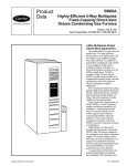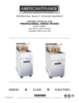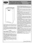
1
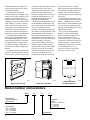
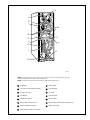
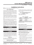
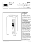
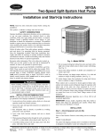
Product Data 58UHV, 58UXV WeatherMaker 8000VS with Comfort Heat Technology™ Deluxe Upflow/Horizontal Furnace Series 120 & 130 Input Capacities: 60,000 thru 120,000 Btuh Comfort Heat Technology with Variable Speed Knowhow Carrier leads the industry with our new WeatherMaker 8000VS Upflow/Horizontal InducedCombustion Gas Furnace. This furnace can operate at a wide range of airflow settings which provide outstanding home comfort. The WeatherMaker 8000VS is built with the most advanced manufacturing equipment, processes, and technology available in order to ensure top quality. Packed into the cabinet are the industry’s foremost dealer and homeowner features. The WeatherMaker 8000VS is the latest addition to Carrier’s list of product leadership in the gas furnace industry. These variable-speed inducedcombustion, gas-fired furnaces offer not only low installation costs, but fuel economy as well — delivering an Annual Fuel Utilization Efficiency (AFUE) rating of 80.0%. The WeatherMaker 8000VS offers outstanding efficiency year round. The efficiency provided by the variablespeed blower motor can add up to 1 point in seasonal energy efficiency ratio (SEER) to an air conditioner or heat pump system. Also, because this motor is so efficient, you can run year-round constant fan guilt-free! In most places it’s less than $30 a year. The Copyright 2000 Carrier Corporation Form 58UHV-4PD EAC-1 PARK check itself, then the low and high inducer speeds, hot surface ignition, and low-, medium-, and high-speed blower operation. The control also features a 3-amp fuse that protects the transformer and control. Enhanced indoor air quality in your home is made easier with our media filter cabinet—a standard accessory on all deluxe furnaces. When installed as a part of your system, this cabinet allows for easy and convenient addition of a Carrier high-efficiency air filter. Best of all, the WeatherMaker 8000VS is easily installed. Many features make this furnace the easy choice for replacement or new construction markets. Left and right connections are provided for gas and electrical supplies. Features include heating and cooling airflow selection, 24 vac humidifier and 115 vac electronic air cleaner connections, and easy-to-remove bottom. 10 11 7 SEC-2 SEC-1 LO-GAS -HEAT FU1 3 L2 EAC-2 3 HI-GAS -HEAT 6 2 HI-COOL 9 5 1 PR2 8 4 L1 7 COM construction. There are no spot welds on the exterior surfaces. There is also double protection for the cabinet. First, a galvanized steel substrate provides resistance to rusting. Then the cabinet is constructed of prepainted steel — the same high-quality finish found on refrigerators and dishwashers. Perhaps the most advanced feature of the WeatherMaker 8000VS is the stateof-the-art microprocessor control which shows true leadership in furnace technology. The simplified electronics in this control provide high reliability while performing many of the functions of older, electro-mechanical devices in other furnaces. Advanced features of the control show Carrier’s true leadership in furnace technology. The control provides blower delay at start-up and shutdown, while monitoring furnace operations and functions. In the unlikely event of a service call, in less than a minute, the technician can use the selftest feature to determine if a major component has failed. The control will PR1 WeatherMaker 8000VS utilizes a hot surface ignition system to save energy and increase reliability. Our design uses the patented S-shaped 4-pass heat exchanger, a soft mount 2-speed inducer assembly, and a 2-stage slow-opening gas valve to minimize sound level. The Super-S heat exchanger provides better heat transfer while enabling us to make a compact furnace. This provides more room in closet, utility room, and short basement installations. The heat exchanger is constructed of aluminized steel and is backed by a 20-year Limited Warranty. The WeatherMaker 8000VS will meet your home heating requirements. This furnace family provides a wide range of heating capacities. All models are GAMA efficiency rating certified. The 58UXV models are certified for use in California Air Quality Management Districts. The superior attention to cabinet detail is obvious. The WeatherMaker 8000VS features 1-piece, seamless, wrap-around 12 9 8 4 5 6 1 2 3 COM 24 V W/W1 Y/Y2 R G HUM 1 TWIN TEST LED MASTER SLAVE 1 1 2 3 4 OFF W2 ON A89217 A93150 HEAT EXCHANGER FURNACE CONTROL A99425 VARIABLE SPEED BLOWER MOTOR Model number nomenclature 58UHV High-Efficiency Induced-Combustion Upflow Furnace Input Capacity 060 — 60,000 Btuh 080 — 80,000 Btuh 100 — 100,000 Btuh 120 — 117,000 Btuh 2 060 120 12 Cooling Size (Airflow) (400 CFM per 12,000 Btuh) 12 — 1200 CFM 16 — 1600 CFM 20 — 2000 CFM Series Number 8 1 2 3 10 4 14 5 13 9 15 6 7 11 12 A95312 NOTE: The Furnaces are for use with natural gas, but can be field-converted for propane gas with a factory-authorized and listed accessory conversion kit. NOTE: Control location and actual control may be different than shown above. 1 Relief Box 2 Gas Valve Control Knob (On/Off) 10 Gas Manifold 3 2-Stage Gas Valve 11 Air Filter 4 Gas Burner 12 Filter Retainer 5 Hot Surface Ignitor 13 Flame Sensor 6 Blower Door Safety Switch 14 Manual Reset Flame Rollout Switches (2) 7 Blower and Blower Motor 15 Status LED Light 8 Draft Safeguard Tube and Switch 9 Rating Plate 3 Carrier accessories* ® A97432 CONTROLS: THERMOSTATS AND ZONING Available in programmable and non-programmable models, Carrier thermostats maintain a constant comfortable temperature level in the home. For the ultimate in home comfort, Carrier’s 2, 4, and 8-zone systems allow temperature control of individual “zones” of the home. This is accomplished through a series of electronic dampers and remote room sensors. The 4-zone system is shown. UNIT SIZE A97380 A91365 MECHANICAL OR ELECTRONIC AIR CLEANER MODEL HUMCCLFP HUMIDIFIER By adding moisture to winter-dry air, a Carrier humidifier can often improve comfort and keep furniture, rugs, and draperies in better condition. Moisturizing household air also helps to retain normal body heat and provides comfort at lower temperatures. Cleans the air of smoke, dirt, and many pollens commonly found. Saves on decorating and cleaning expenses. 060-12** 080-16 100-20 FILCCFTC0016 FILCCFTC0020 Model AIRA ELECTRONIC AIR CLEANER (EAC) CARRIER MEDIA FILTER (2 PACK) MECHANICAL AIR CLEANER HUMIDIFIER Model HUM Models VA3B, VB5B, or VC5B ENERGY RECOVERY VENTILATOR THERMOSTAT—PROGRAMMABLE Model VL3A Auto Changeover, °F/°C, 1-Stage Heat/1-Stage Cool—TSTATCCNAC01-B Auto Changeover, °F/°C, 2-Stage Heat/1-Stage Cool—TSTATCCNHP01-B Auto Changeover, °F/°C, 2-Stage Heat/2-Stage Cool—TSTATCCN2S01-B in AC Mode, 3-Stage Heat in AC Mode/2-Stage Cool in HP Mode Air Conditioner, 1-Stage Heat/1-Stage Cool, Manual Changeover, °F/°C—TSTATCCBAC01 Heat Pump, 2-Stage Heat/1-Stage Cool, Manual Changeover, °F/°C—TSTATCCBHP01** Auto Changeover, 7-Day Programmable, °F/°C, 1-Stage Heat/1-Stage Cool—TSTATCCPAC01-B Auto Changeover, 7-Day Programmable, °F/°C, 2-Stage Heat/1-Stage Cool—TSTATCCPHP01-B Auto Changeover, 7-Day Programmable, °F/°C, 2-Stage Heat/2-Stage Cool—TSTATCCP2S01-B in AC Mode, 3-Stage Heat/2-Stage Cool in HP Mode Dual Fuel Thermostat, includes Outdoor Air Temperature Sensor—TSTATCCPDF01-B** Thermidistat Control—Non-Programmable/Programmable Thermostat—TSTATCCPRH01-B** with Humidity Control (For use in Dual Fuel, AC, HP, and 2S applications. Includes Outdoor Air Temperature Sensor.) ZONING—2 ZONE ZONECC2KIT01, ZONEKIT2ZCAR ZONING—4 ZONE ZONECC4KIT01 ZONING—8 ZONE ZONECC8KIT01 TWINNING KIT† KGATW0401HSI GAS CONVERSION KIT* — NATURAL-TO-PROPANE KGANP2001ALL PROPANE-TO-NATURAL KGAPN1601ALL VARIABLE SPEED BLOWER MOTOR REPLACEMENT CONTROL MODULE RMOD44AE120,121 RMOD44AE120,121 * Factory authorized and field installed. Gas conversion kits are C.S.A. (A.G.A. and C.G.A.) recognized. † 16 and 20 models only. ** Do not use in zoning heat pump applications. 4 FILCCFTC0024 Model 31MF HEAT RECOVERY VENTILATOR THERMOSTAT—NON-PROGRAMMABLE 120-20 RMOD46AE120 RMOD52AE121 A99273 28 1⁄2˝ VENT CONN 5 3⁄ 8˝ 12 5⁄16˝ 2 3⁄8˝ 1 3⁄4-IN. DIA HOLE GAS ENTRY HOLE THERMOSTAT WIRE ENTRY 1 1⁄2-IN. DIA R.H. GAS ENTRY 7⁄8-IN. DIA ACCESSORY 1⁄2-IN. DIA THERMOSTAT WIRE ENTRY 2 3⁄8˝ 1⁄2-IN. DIA 7⁄8-IN. DIA POWER ENTRY 2 11⁄16˝ 5 13⁄16˝ 5 13⁄16˝ 13⁄16˝ OUTLET 1˝ 5 3⁄8˝ HOLE POWER ENTRY 7⁄8-IN. DIA ACCESSORY 19˝ 13⁄16˝ 1˝ 7⁄8-IN. DIA 39 7⁄8˝ 2 1⁄16˝ A D 2 1⁄16˝ SIDE INLET (FOR UPFLOW INSTALLATION ONLY) SIDE INLET (FOR UPFLOW INSTALLATION ONLY) 141⁄2˝ TYP 1˝ 11⁄4˝ 11⁄16˝ 24 5⁄16˝ 3˝ 11⁄16˝ AIR INLET DIMPLES TO DRILL HOLES FOR HANGER BOLTS: 8 PLACES (FOR HORIZONTAL INSTALLATIONS ONLY) 11⁄16˝ E 1˝ 231⁄4˝ SIDE RETURN DUCT LOCATION 5⁄8˝ TYP NOTES: 1. Two additional 7⁄8-in. dia holes are located in the top plate. 2. Minimum return-air openings at furnace, based on metal duct. If flex duct is used, see flex duct manufacturer's recommendations for equivalent diameters. AIRFLOW a. For 800 CFM–16-in. round or 141⁄2 x 12-in. rectangle. b. For 1200 CFM–20-in. round or 141⁄2 x 191⁄2-in. rectangle. c. For 1600 CFM–22-in. round or 141⁄2 x 231⁄4-in. rectangle. d. For airflow requirements above 1800 CFM, see Air Delivery table in Product Data literature for specific use of single side inlets. The use of both side inlets, a combination of 1 side and the bottom, or the bottom only will ensure adequate return air openings for airflow requirements above 1800 CFM. A00358 DIMENSIONS (In.) A D 060-12 14-3/16 12-9/16 12-11/16 4 16'' 080-16 21 19-3/8 19-1/2 4 20'' 100-20 24-1/2 22-7/8 23 4 24'' 120-20 24-1/2 22-7/8 23 5 24'' E VENT CONNECTION* MEDIA CABINET SUPPLIED UNIT SIZE * Refer to the furnace Installation Instructions for proper venting procedures. 5 Physical data 060-12 080-16 100-20 120-20 OUTPUT CAPACITY (BTUH)† UNIT SIZE High Stage 49,000 65,000 82,000 96,000 Nonweatherized ICS Low Stage 31,000 42,000 53,000 63,000 GAS INPUT (BTUH)* High Stage 60,000 80,000 100,000 117,000 Low Stage 39,000 52,000 65,000 78,000 134 154 184 194 SHIPPING WEIGHT (LB) CERTIFIED TEMP RISE High Stage 25-55 30-60 25-55 40-70 RANGE (°F) Low Stage CERTIFIED EXT STATIC PRESSURE (In. wc) AIRFLOW CFM‡ 15-45 15-45 15-45 25-55 Heating 0.12 0.15 0.20 0.20 Cooling 0.7 0.5 0.7 0.7 1250/1135 1310/1395 1935/1630 1720/1605 1260 1635 2085 2110 Heating High/Low Cooling (Max) LIMIT CONTROL SPST (Auto-Reset) HEATING BLOWER CONTROL Solid-State Time Operation INDUCER 2-Speed BURNERS (Monoport) 3 4 6 5 GAS CONNECTION SIZE 1/2-in. NPT GAS VALVE (Redundant) Manufacturer White-Rodgers Minimum Inlet Pressure (In. wc) 4.5 (Natural Gas) Maximum Inlet Pressure (In. wc) 13.6 (Natural Gas) IGNITION DEVICE Hot Surface * Gas input ratings are certified for elevations to 2000 ft. For elevations above 2000 ft, reduce ratings 4% for each 1000 ft above sea level. Refer to National Fuel Gas Code Table F4. In Canada, derate the unit 10% for elevations 2000 ft to 4500 ft above sea level. † Capacity and AFUE in accordance with U.S. Government DOE test procedures. ‡ • Airflow shown is for bottom only return-air supply with factory-supplied 1-in. washable filter(s). • For air delivery above 1800 CFM, see Air Delivery table for other options. • An airflow reduction of up to 7% may occur when using the factory-specified 4 5/16-inch wide, high efficiency media filter. • For best furnace efficiency when using the 4 5/16-inch wide media filter, adjust the blower speed tap to near the mid-point of the rise range. ICS — Isolated Combustion System Performance data UNIT SIZE 060-12 080-16 100-20 120-20 DIRECT-DRIVE MOTOR Hp (ECM Variable Speed) 1/2 1/2 3/4 1 MOTOR FULL LOAD AMPS 7.7 7.7 9.6 12.0 RPM (Nominal) — SPEEDS 300 to 1400 300 to 1400 300 to 1400 300 to 1400 10 x 6 10 x 8 11 x 10 11 x 10 WASHABLE 16 x 25 x 1-in. FILTER — QTY 1 — — — WASHABLE 20 x 25 x 1-in. FILTER — QTY — 1 — — WASHABLE 24 x 25 x 1-in. FILTER — QTY — — 1 1 BLOWER WHEEL DIAMETER X WIDTHS (In.) ECM — Electronically Commutated Motor Efficiency 060-12 080-16 100-20 120-20 High Stage 49,000 65,000 82,000 96,000 Low Stage 31,000 42,000 53,000 63,000 80.0 80.0 80.0 80.0 UNIT SIZE CAPACITY BTUH* AFUE %* Nonweatherized ICS *Capacity and AFUE in accordance with U.S. Government DOE test procedures. ICS — Isolated Combustion System ama MEETS DOE RESIDENTIAL CONSERVATION SERVICES PROGRAM STANDARDS. Before purchasing this appliance, read important energy cost and efficiency information available from your retailers. 6 CERTIFIED Carrier Evaporator Coil & Furnace Match Up Guide CK5 Cased Coil A036 T036 N042 N048 A042 T042 A048 T048 N060 W048 A060 T060 X060 17 1/2 17 1/2 17 1/2 17 1/2 17 1/2 17 1/2 21 21 21 21 21 21 24 1/2 24 1/2 24 1/2 24 1/2 W036 W024 14 3/16 W030 N036 14 1/5 21 24 1/2 24 1/2 14 3/16 018-036 030-048 036-060 036-060 A030 060-12 080-16 100-20 120-20 14 3/16 Furnace Width (inches) A024 Nominal Cooling Size 14 3/16 58UHV 58UXV (Upflow) Size A018 Furnace Model Numbers ■ - ■ - ■ - ■ - - ▲ - ▼ - ❏ - ▼ - - ■ ▲ ▲ ■ ▲ ▲ ■ - ■ - - ■ - ■ ■ ■ ■ - ■ ■ CD5A W024 W030 A036 W036 A042 W042 A048 C048 W048 A060 W060 17 1/2 17 1/2 17 1/2 21 21 24-1/2 21 21 24 1/2 24 1/2 31-1/2 14 1/5 21 24 1/2 24 1/2 14 3/16 018-036 030-048 036-060 036-060 A030 060-12 080-16 100-20 120-20 14 3/16 Furnace Width (inches) A024 Nominal Cooling Size 14 3/16 58UHV 58UXV (Upflow) Size A018 Furnace Model Numbers ■ - ■ - ■ - ❏ - ❏ ▲ - ❏ ▲ S S ▼ ■ ▲ ▲ ▼ ■ ▲ ▲ ❏ ■ ■ ■ ▲ ▲ ■ ▲ ▲ ❏ ■ ■ ❏ ■ ■ ❏ ❏ CC5A Uncased W024 W030 A036 A042 W042 C048 W048 A060 W060 17 1/2 17 1/2 17 1/2 21 24-1/2 21 24 1/2 24 1/2 31-1/2 14 1/5 21 24 1/2 24 1/2 14 3/16 018-036 030-048 036-060 036-060 A030 060-12 080-16 100-20 120-20 14 3/16 ■ - ■ - ■ - ❏ - ❏ ▲ - ❏ ▲ S S ▼ ■ ▲ ▲ ❏ ■ ■ ■ ▲ ▲ ❏ ■ ■ ❏ ■ ■ ❏ ❏ 024 Size Furnace Width (inches) 17 1/2 17 1/2 21 21 24 1/2 Horizontal CK3 Indoor Coil 030 036 042 048 Nominal Cooling Size 17 1/2 58UHV 58UXV (Horizontal) Furnace Width (inches) A024 Furnace Model Numbers Nominal Cooling Size 14 3/16 58UHV 58UXV (Upflow) Size A018 Furnace Model Numbers 060 060-12 080-16 100-20 120-20 018-036 030-048 036-060 036-060 14 1/5 21 21 24 1/2 B - B T - B T T T T ■ ■ T ■ ■ T B B ■ LEGEND ■ - Coil and furnace are flush ❏ - Coil is wider than furnace, has factory ““transition plates”” to fit several furnace sizes” ▲ - Coil is narrower than the furnace. A transition will be required ▼ - Coil is wider than the furnace. Follow overhang instructions S - Coil is more than 1 size different than the furnace. Special consideration required T - Coil is narrower than the furnace or is more than 1 size wider. A transition will be required B - Coil is wider than the furnace. Apply standard blockoff plate 7 AIR DELIVERY — NOMINAL CFM at up to 0.70 i.w.c. E.S.P. (With filter) GAS HEAT AIRFLOW GAS HEAT TEMP RISE GAS HEAT TEMP RISE (°F)* JUMPER POSITION‡ FURNACE SIZE GAS HEAT AIRFLOW (CFM) Red Wire Violet Wire HIGH-STAGE LOW-STAGE HIGH-STAGE LOW-STAGE 060 HI M-HI MID A A D 51 46 40 45 38 30 925 1085 1250 615 730 1135 080 HI M-HI MID A A D 58 51 45 44 39 29 970 1140 1310 790 925 1395 100 HI M-HI MID A A D 51 45 40 44 39 30 1430 1685 1935 1035 1215 1630 120 HI M-HI MID A A D 69 59 55 49 43 40 1330 1560 1720 1240 1460 1605 AC/HP JUMPER POSITION: AC AIR CONDITIONING, COOLING AIRFLOW HP — EFFY HEAT PUMP — EFFICIENCY, COOLING AND HEATING AIRFLOW HP — CFMT HEAT PUMP — COMFORT, COOLING AIRFLOW SINGLE-SPEED AIRFLOW SELECTION COOL SIZE TWO-SPEED (HIGH / LOW) CFM CFM COOL CFM PER TON COOL CFM PER TON JUMPER POSITION JUMPER JUMPER POSITION 400 FURNACE SIZE POSITION TONS 400 350 060 LO M-LO M-HI HI 1-1/2 2 2-1/2 3 600 800 1000 1200 530 700 880 1050 080 LO M-LO M-HI HI 2-1/2 3 3-1/2 4 1000 1215 1400 1600** 875 1050 1225 1400 790 945 1100 1250 1050 1260 1470 1635** 100 LO M-LO M-HI HI 3 3-1/2 4 5 1195 1400 1600 2000 1045 1225 1400 1750 950 1090 1260 1575 120 LO M-LO M-HI HI 3 3-1/2 4 5 1160 1400 1600 2000 1050 1220 1395 1750 955 1090 1250 1565 AC/HP JUMPER POSITION: HP — CMFT 315 500† 630 790 945 HIGH 350 LOW 630 865 1060 1260 500† 510 650 780 315 LOW HIGH LOW 550 735 920 1100 500† 500† 570 680 660 790 910 1040 920 1100 1280 1470 595 700 805 915 830 990 1155 1325 545 625 715 820 1260 1470 1680 2085 780 910 1040 1300 1090 1285 1465 1840 775 830 915 1150 990 1155 1325 1655 700† 715 820 1025 1195 1420 1650 2110 865 970 1070 1300 1085 1265 1465 1835 785 875 975 1140 985 1150 1315 1640 785 845 930 1080 500† 660 825 990 500† 500† 510 585 HEAT PUMP — COMFORT, HEATING AIRFLOW SINGLE-SPEED AIRFLOW SELECTION COOL SIZE HIGH TWO-SPEED (HIGH / LOW) CFM CFM COOL CFM PER TON COOL CFM PER TON JUMPER POSITION JUMPER JUMPER POSITION FURNACE SIZE POSITION TONS 400 060 LO M-LO M-HI HI 1-1/2 2 2-1/2 3 540 720 900 1080 080 LO M-LO M-HI HI 2-1/2 3 3-1/2 4 900 1080 1260 1440 785 945 1100 1260 100 LO M-LO M-HI HI 3 3-1/2 4 5 1075 1260 1440 1800 120 LO M-LO M-HI HI 3 3-1/2 4 5 1045 1260 1440 1800 350 500† 630 790 945 400 315 500† 570 710 855 HIGH 350 LOW HIGH 315 LOW HIGH LOW 565 780 945 1135 500† 500† 585 700 710 850 990 1135 945 1135 1325 1510 605 715 830 940 825 990 1150 1325 535 630 725 825 755 895 1040 1190 500† 560 655 740 940 1100 1260 1575 855 990 1130 1420 1130 1325 1510 1890 700 820 935 1170 980 1155 1320 1655 700 750 825 1035 890 1040 1190 1490 700† 700† 740 920 945 1100 1255 1575 860 980 1125 1410 1075 1280 1485 1900 780 875 965 1170 975 1140 1320 1650 750 790 880 1025 885 1035 1185 1475 750 760 835 970 500† 660 830 990 500† 500† 515 610 500† 595 740 895 500† 500† 500† 555 Within ± 2°F Minimum airflow is set for electronic air cleaner: 060—500 CFM, 080—500 CFM, 100—700 CFM, 120—700 CFM Use only listed jumper position combinations. Maximum available ESP is 0.70 iwc for all furnace model sizes and operating modes, except maximum available ESP is 0.50 iwc for HI cool size airflow at 400 cfm per ton selection with the 080 size furnace. NOTES: 1. A humidistat can be used to further reduce airflow when increased humidity is sensed. This feature reduces the selected airflow by 20%, but no lower than 280 CFM per ton. 2. Continuous-fan selections are 50%, 65%, or 100% of selected cooling airflow. 100% is not recommended for 2-speed air conditioning or heat pumps.† 3. See the following airflow curves for CFM versus ESP at 350 CFM per ton. 4. Airflow shown is with factory supplied 1-in. washable filter(s). An airflow reduction of up to 7% may occur when using the factory-specified 4 5/16-inch wide, high-efficiency media filter. For best furnace efficiency when using the 4 5/16-inch wide media filter, adjust the blower speed tap to near the mid-point of the rise range. * † ‡ ** 8 The airflow performance charts for the model 58UHV and 58UXV Furnaces provide nominal airflow in cubic ft per minute (CFM) versus external static pressure (ESP) in in. water column (IWC) for gas heating, cooling, and heat pump operating modes. Each model has 2 chart pages: gas heating and single-speed cooling on the first page, and 2-speed cooling on the second page. Gas heating airflow is shown with dashed lines for HIGHGAS HEAT and with dot-dash lines and return-air duct system at any airflow, if a single actual airflow CFM versus ESP is known. for LOW-GAS HEAT for all 3 air temperature rise selections. Single-speed cooling airflow is shown with solid lines for all 4 size selections. Twospeed airflow is shown with solid lines for HIGH-COOLING and with dot-dash for lines LOW-COOLING for all 4 size selections. Example: If CFM and ESP at point A in example below are known, the CFM and ESP at point B can be determined by following the system curve from A to B. If a point falls between 2 system curves, follow an imaginary system curve parallel to and between the 2 system curves. The curved, dotted lines are furnaceduct system characteristic curves. System curves can be used to predict the ESP imposed by a building’s supply- EXAMPLE AIRFLOW (CFM versus ESP) A COOLING FURNACE-DUCT SYSTEMS GAS HEATING EXTERNAL STATIC PRESSURE (IWC) FURNACE AIRFLOWS 0.4 B 0 840 1050 1300 CFM A96033 9 FURNACE SIZE 60,000 BTUH HEATING INPUT 36,000 BTUH COOLING 0.9 *See Air Delivery Table for TWO-STAGE GAS HEATING WITH FILTER jumper positions. SINGLE-SPEED COOLING WITH FILTER COOLING AIRFLOW SELECTION IS APPROXIMATELY 350 CFM PER TON Airflow shown is with factory supplied 1-in. washable filter(s). For airflow using the factory specified 4 5/16-inch wide, high-efficiency media filter, see media filter pressure drop information from media filter product data. MID (HIGH-GAS HEAT 40°F AIR TEMP RISE)* 1250 MID (LOW-GAS HEAT 30°F AIR TEMP RISE)* 1135 1085 1050 925 880 730 530 0.1 700 0.2 615 HI (LOW-GAS HEAT 45°F AIR TEMP RISE)* M-HI (LOW-GAS HEAT 38°F AIR TEMP RISE)* 0.4 M-HI (HIGH-GAS HEAT 46°F AIR TEMP RISE)* 0.5 0.3 HI (3 TONS COOLING) HI (HIGH-GAS HEAT 51°F AIR TEMP RISE)* M-LO (2 TONS COOLING) 0.6 LO (1-1/2 TONS COOLING) EXTERNAL STATIC PRESSURE (IWC) 0.7 M-HI (2-1/2 TONS COOLING) 0.8 3-14-96 0 400 500 600 700 800 900 1000 1100 1200 1300 CFM A96019 10 FURNACE SIZE 60,000 BTUH HEATING INPUT 36,000 BTUH COOLING TWO-SPEED COOLING WITH FILTER COOLING AIRFLOW SELECTION IS APPROXIMATELY 350 CFM PER TON Airflow shown is with factory supplied 1-in. washable filter(s). An airflow reduction of up to 7% may occur when using the factory specified 4 5/16-inch wide, high-efficiency media filter. 0.9 0.8 0.6 HI (3 TONS HIGH COOLING) M-HI (2-1/2 TONS HIGH COOLING) 1100 920 735 M-LO (2 TONS HIGH COOLING) HI (3 TONS LOW COOLING) 680 0.1 M-HI (2-1/2 TONS LOW COOLING) 0.2 LO (1-1/2 TONS HIGH COOLING) 0.3 550 570 0.4 M-LO AND LO (2 AND 1-1/2 TONS LOW COOLING) 0.5 500 EXTERNAL STATIC PRESSURE (IWC) 0.7 10-20-95 0 400 500 600 700 800 900 1000 1100 1200 1300 CFM A96020 11 FURNACE SIZE 80,000 BTUH HEATING INPUT 48,000 BTUH COOLING 0.9 *See Air Delivery Table for jumper positions. TWO-STAGE GAS HEATING WITH FILTER SINGLE-SPEED COOLING WITH FILTER COOLING AIRFLOW SELECTION IS APPROXIMATELY 350 CFM PER TON Airflow shown is with factory supplied 1-in. washable filter(s). An airflow reduction of up to 7% may occur when using the factory specified 4 5/16-inch wide, high-efficiency media filter. 0.8 HI (4 TONS COOLING) MID (LOW-GAS HEAT 29°F AIR TEMP RISE)* 1395 1400 M-HI (3-1/2 TONS COOLING) M-HI (HIGH-GAS HEAT 51°F AIR TEMP RISE)* M-LO (3 TONS COOLING) MID (HIGH-GAS HEAT 45°F AIR TEMP RISE)* 1310 875 790 0.1 1225 0.2 1140 0.3 1050 M-HI (LOW-GAS HEAT 39°F AIR TEMP RISE)* 0.4 HI (HIGH-GAS HEAT 58°F AIR TEMP RISE)* 0.5 925 970 LO (2-1/2 TONS COOLING) 0.6 HI (LOW-GAS HEAT 44°F AIR TEMP RISE)* EXTERNAL STATIC PRESSURE (IWC) 0.7 3-14-96 0 600 700 800 900 1000 1100 1200 1300 1400 1500 1600 1700 CFM A96021 12 FURNACE SIZE 80,000 BTUH HEATING INPUT 48,000 BTUH COOLING TWO-SPEED COOLING WITH FILTER COOLING AIRFLOW SELECTION IS APPROXIMATELY 350 CFM PER TON Airflow shown is with factory supplied 1-in. washable filter(s). An airflow reduction of up to 7% may occur when using the factory specified 4 5/16-inch wide, high-efficiency media filter. 0.9 0.8 0.6 HI (4 TONS HIGH COOLING) M-HI (3-1/2 TONS HIGH COOLING) M-LO (3 TONS HIGH COOLING) LO (2-1/2 TONS HIGH COOLING) HI (4 TONS LOW COOLING) 0.3 M-LO (3 TONS LOW COOLING) 0.4 M-HI (3-1/2 TONS LOW COOLING) 0.5 LO (2-1/2 TONS LOW COOLING) 1470 1275 1100 915 915 805 0.1 700 0.2 595 EXTERNAL STATIC PRESSURE (IWC) 0.7 10-20-95 0 400 500 600 700 800 900 1000 1100 1200 1300 1400 1500 1600 CFM A96022 13 FURNACE SIZE 100,000 BTUH HEATING INPUT 60,000 BTUH COOLING *See Air Delivery Table for jumper positions. TWO-STAGE GAS HEATING WITH FILTER SINGLE-SPEED COOLING WITH FILTER COOLING AIRFLOW SELECTION IS APPROXIMATELY 350 CFM PER TON Airflow shown is with factory supplied 1-in. washable filter(s). An airflow reduction of up to 7% may occur when using the factory specified 4 5/16-inch wide, high-efficiency media filter. 0.9 0.8 1935 1750 MID (HIGH-GAS HEAT 40°F AIR TEMP RISE)* M-HI (HIGH-GAS HEAT 45°F AIR TEMP RISE)* 1685 1630 1400 1430 0.1 1215 1225 0.2 M-HI (LOW-GAS HEAT 39°F AIR TEMP RISE)* 0.4 MID (LOW-GAS HEAT 30°F AIR TEMP RISE)* HI (HIGH-GAS HEAT 51°F AIR TEMP RISE)* 0.5 0.3 HI (5 TONS COOLING) M-HI (4 TONS COOLING) M-LO (3-1/2 TONS COOLING) LO (3 TONS COOLING) 0.6 1035 HI (LOW-GAS HEAT 44°F AIR TEMP RISE)* 1045 EXTERNAL STATIC PRESSURE (IWC) 0.7 3-14-96 0 600 700 800 900 1000 1100 1200 1300 1400 1500 1600 1700 1800 1900 2000 2100 CFM A96023 14 FURNACE SIZE 100,000 BTUH HEATING INPUT 60,000 BTUH COOLING TWO-SPEED COOLING WITH FILTER COOLING AIRFLOW SELECTION IS APPROXIMATELY 350 CFM PER TON Airflow shown is with factory supplied 1-in. washable filter(s). An airflow reduction of up to 7% may occur when using the factory specified 4 5/16-inch wide, high-efficiency media filter. 0.9 0.8 HI (5 TONS HIGH COOLING) M-HI (4 TONS HIGH COOLING) M-LO (3-1/2 TONS HIGH COOLING) HI (5 TONS LOW COOLING) 0.4 LO (3 TONS HIGH COOLING) 0.5 M-HI (4 TONS LOW COOLING) LO (3 TONS LOW COOLING) M-LO (3-1/2 TONS LOW COOLING) 0.6 0.3 1840 1465 1285 1150 1090 915 0.1 830 0.2 755 EXTERNAL STATIC PRESSURE (IWC) 0.7 10-20-95 0 600 700 800 900 1000 1100 1200 1300 1400 1500 1600 1700 1800 1900 CFM A96024 15 FURNACE SIZE 120,000 BTUH HEATING INPUT 60,000 BTUH COOLING TWO-STAGE GAS HEATING WITH FILTER SINGLE-SPEED COOLING WITH FILTER COOLING AIRFLOW SELECTION IS APPROXIMATELY 350 CFM PER TON Airflow shown is with factory supplied 1-in. washable filter(s). An airflow reduction of up to 7% may occur when using the factory specified 4 5/16-inch wide, high-efficiency media filter. 0.9 HI (5 TONS COOLING) MID (HIGH-GAS HEAT 55°F AIR TEMP RISE) 1720 1750 1605 MID (LOW-GAS HEAT 40°F AIR TEMP RISE) M-HI (HIGH-GAS HEAT 59°F AIR TEMP RISE) 1560 1050 0.1 1220 0.2 M-HI (LOW-GAS HEAT 43°F AIR TEMP RISE) 0.3 1395 0.4 1330 0.5 1240 HI (LOW-GAS HEAT 49°F AIR TEMP RISE) HI (HIGH-GAS HEAT 69°F AIR TEMP RISE) 0.6 1460 LO (3 TONS COOLING) EXTERNAL STATIC PRESSURE (IWC) 0.7 M-HI (4 TONS COOLING) M-LO (3-1/2 TONS COOLING) 0.8 10-24-95 0 600 700 800 900 1000 1100 1200 1300 1400 1500 1600 1700 1800 1900 2000 2100 CFM A96025 16 FURNACE SIZE 120,000 BTUH HEATING INPUT 60,000 BTUH COOLING TWO-SPEED COOLING WITH FILTER COOLING AIRFLOW SELECTION IS APPROXIMATELY 350 CFM PER TON Airflow shown is with factory supplied 1-in. washable filter(s). An airflow reduction of up to 7% may occur when using the factory specified 4 5/16-inch wide, high-efficiency media filter. 0.9 0.8 HI (5 TONS HIGH COOLING) M-HI (4 TONS HIGH COOLING) M-LO (3-1/2 TONS HIGH COOLING) HI (5 TONS LOW COOLING) LO (3 TONS HIGH COOLING) 0.4 M-HI (4 TONS LOW COOLING) 0.5 M-LO (3-1/2 TONS LOW COOLING) LO (3 TONS LOW COOLING) 0.6 0.3 1835 1465 1265 1140 1085 975 0.1 875 0.2 785 EXTERNAL STATIC PRESSURE (IWC) 0.7 10-24-95 0 600 700 800 900 1000 1100 1200 1300 1400 1500 1600 1700 1800 1900 CFM A96026 17 Typical wiring schematic FIELD 24-V WIRING FIELD 115-, 208/230-, 460-V WIRING FACTORY 24-V WIRING FACTORY 115-V WIRING NOTE 2 W FIVE WIRE C Y R G 1-STAGE THERMOSTAT TERMINALS FIELD-SUPPLIED FUSED DISCONNECT THREE-WIRE HEATINGONLY 115-V FIELDSUPPLIED DISCONNECT BLK BLK WHT WHT 208/230- OR 460-V THREE PHASE W2 COM 208/230-V SINGLE PHASE W/W1 GND NOTE 1 Y/Y2 JUNCTION BOX CONTROL GREEN DEHUM NOTE 6 R GND CONDENSING UNIT G NOTE 4 24-V Y1 NOTES: 1. Connect Y/Y2-terminal as shown for proper operation. TERMINAL 2. Some thermostats require a "C" terminal connection as shown. BLOCK 3. If any of the original wire, as supplied, must be replaced, use FURNACE same type or equivalent wire. 4. Y1 is not to be connected. NOTE 5 5. Connect O to thermostat-O only for heat pump applications. O 6. Field-supplied humidistat for dehumidification in cooling (optional). AFS A99231 FIELD 24-V WIRING FIELD 115-, 208/230-, 460-V WIRING FACTORY 24-V WIRING FACTORY 115-V WIRING NOTE 2 C 115-V FIELDSUPPLIED DISCONNECT WHT Y2 SEVEN WIRE FOUR-WIRE HEATINGONLY R G Y1 2-STAGE THERMOSTAT TERMINALS FIELD-SUPPLIED FUSED DISCONNECT 208/230- OR 460-V THREE PHASE W2 BLK BLK W1 W2 COM WHT 208/230-V SINGLE PHASE W/W1 GND Y/Y2 JUNCTION BOX CONTROL GREEN DEHUM NOTE 1 Y1 Y2 R G NOTE 5 AFS 24-V TERMINAL BLOCK FURNACE C Y1 NOTE 4 O GND 2-SPEED CONDENSING UNIT NOTES: 1. Connect Y1 and Y/Y2 as shown for proper operation. 2. Some thermostats require a "C" terminal connection as shown. 3. If any of the original wire, as supplied, must be replaced, use same type or equivalent wire. 4. Connect O to thermostat-O only for heat pump applications. 5. Field-supplied humidistat for dehumidification in cooling (optional). A99232 18 Electrical data UNIT SIZE 060-12 080-16 UNIT VOLTS — HERTZ — PHASE 100-20 120-20 14 115 — 60 — 1 MINIMUM WIRE SIZE 14 14 14 MAXIMUM WIRE LENGTH (Ft)* 36 34 29 26 10.1 10.6 12.6 13.9 MAXIMUM UNIT AMPS OPERATING VOLTAGE RANGE (Min — Max)† 104 — 127 MAX FUSE CKT BKR (Amps)‡ 15 TRANSFORMER (24v) 40va EXTERNAL CONTROL POWER AVAILABLE Heating 19va Cooling 35va AIR CONDITIONING BLOWER RELAY Standard * Length shown is as measured 1 way along wire path between unit and service panel for maximum 2% voltage drop. † Permissible limits of the voltage range at which the unit will operate satisfactorily. ‡ Time-delay fuse is recommended. Typical installations CONDENSING UNIT HUMIDIFIER ELECTRONIC AIR CLEANER GAS-FIRED WATER HEATER AIRFLOW A89242 19 MEDIA FILTER CABINET 25 5/8" 23 5/8" 24 3/8" Opening with Flanges Bent 23 3/8" 23 1/8" Opening B Opening A Furnace Side Duct Side 23 3/4" Centerline Screw Slots 5 3/4" Media/ Filter Cabinet A B 16" 17 16" 20" 21 20" 24" 25 24" A00309 Carrier Corporation • Indianapolis, IN 46231 10-00 Manufacturer reserves the right to discontinue, or change at any time, specifications or designs without notice and without incurring obligations. Book 1 Tab 6a 8a 4 Page 20 Catalog No. 525-80007 Printed in U.S.A. PC 101 Form 58UHV-4PD Replaces: 58UHV-3PD