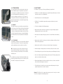
1
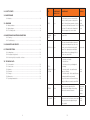
UK 7.0. TECHNICAL DATA 7.0.1. SERIES NUMBER The series number can be found on the frame near the left flywheel. 7.0.2. POWER SOURCE 2 units ME 180W 24V worm geared motor units. Built-in electro-mechanical holding brake. 7.0.3. BATTERIES 2 x 12V 33Ah gel maintenance-free wheelchair batteries. Charging time approx. 8 hours with the battery charger. 7.0.4. ELECTRONICS Electricity grid 24 Volt DC SignalAnalogue cabling Electric liftVELA MBL actuator 180-24 VDC Tilt actuator Linak RA40 24 VDC Electric back actuatorLinak LA28 100 Motor controlVELA ET3.2 24VDC PG Drives combined wheelchair electronics VR2. 7.0.5. CHARGER Automatic Power Charger 8Ah 230V AC / 24V DC 7.0.6. DIMENSIONS Seating height 48 - 68 cm Seat height from edge (empty) 52 cm Overall height without seat 40 cm 61 cm 100 cm 5 cm 10” (260x85mm) flexell 8” (260x85mm) flexell 13° backwards, 4 ° forwards 24° (90° to 114°) 8 km/t 22 km/t 12° 4 cm 53 cm 125 kg VELA · Goeteborgvej 12 · DK-9200 Aalborg SV · Denmark · Tel: +45 96 34 76 00 · [email protected] · www.vela.eu VELA Blues 300 UK - June 2013 Carriage width Carriage length with 1 footplate down Clearance Traction wheel Flywheel Seat angling with electric tilting Back angling with manual back 7.0.7. OPERATING CHARACTERISTICS Max. speed Range Climbing ability max. Obstacle max. Turning radius Max. load U S E R M A N U A L 6.0.2. PASSENGER SEAT (OPTIONAL) VELA Blues 300 can be configured for use as the passenger seat of a car. The chair must be constructed as below, and the work must be carried out by a VELA technician or suitably trained personnel. Configuration for use as a passenger seat For the VELA Blues 100 – 200 – 300 to be used as the passenger seat in a car, the chair must be configured as shown b - SW seat and back system (width 40 – 45 – 50 cm) - WB head rest - Folding or fixed armrest - Electric or manual chair back - Electrically operated leg support or E-leg support + swivel footrest 6.0.3. POSITIONING THE 3-POINT SEAT BELT ON THE USER IMPORTANT: The 3-point seat belt must not be tightened across sharp edges. The drawing illustrates the incorrect positioning of a 3-point seat belt. The seatbelts must not be held away from the body by parts of the wheelchair, such as armrests, wheels, etc. THESE TWO DRAWINGS ILLUSTRATE THE CORRECT POSITIONING OF A 3-POINT SEATBELT The seatbelt must have full contact with the shoulder, chest and hips. The lap belt must be positioned as close as possible to the hips. 23 5.0. WARRANTY AND SERVICE VELA refers to the Danish Sale of Goods Act with regard to warranty. The warranty applies only if original spare parts and accessories are used, and always provided that adjustments are carried out by authorised service technicians. VELA assumes no liability for damage to the product or injury to the user as a result of: • Transport • Misuse • Ordinary wear and tear • Incorrect use • Using non-original spare parts and accessories • Adjustments carried out by unauthorised service technicians 6.0. TRANSPORT The height of the powerchair can be reduced to approx. 85 cm by folding the chair back across the seat. Loosen the pin on the chair back and remove it. Then fold the chair back across the seat. 6.0.1. LASHING RINGS The chair can be fitted with a lashing ring which is used if the chair is to be transported by car, bus or train. The lashing rings can only be mounted if the chair is configured with a C-profile seat frame. (Contact VELA for further information) Warning! The VELA Blues 300 is not approved as a passenger seat for use in cars, buses or trains. Always make sure that the powerchair is secured using approved lashing equipment during transport in cars, buses, trains etc. CONTENTS 1.0. USER MANUAL................................................................................................................ 6 1.1. BEFORE OPERATION...................................................................................................... 6 1.1.1. Entry and exit............................................................................................................... 1.1.2. Foot plate..................................................................................................................... 1.1.3. Assistance getting off.................................................................................................. 1.1.4. Seat rotation................................................................................................................ 6 6 7 7 1.2. SITTING POSITION......................................................................................................... 8 1.2.1. Arm rest....................................................................................................................... 1.2.2. Seating height............................................................................................................. 1.2.3. Back rest...................................................................................................................... 1.2.4. Neck support .............................................................................................................. 1.2.5. Seat depth................................................................................................................... 1.2.6. Electric tilt / seat angle................................................................................................. 8 8 9 9 10 10 1.3 DRIVING 1.3.1. VR2 control box........................................................................................................... 1.3.2. R-Net control box (optional)........................................................................................ 1.3.3. Steering with the Joystick............................................................................................ 1.3.4. Description of the wheelchair’s steering...................................................................... 11 11 12 12 1.3.5. Driving over obstacles.................................................................................................. 13 1.3.6. Driving on slanting surface.......................................................................................... 13 1.3.7. Braking........................................................................................................................ .13 1.3.8. Electro-brake............................................................................................................... 13 1.3.8.1. Friction coupling............................................................................................. 14 1.3.9. Stationary and parking................................................................................................. 14 The chair is not designed to be lifted during transport. 1.4. FOOT SUPPORTS 1.4.1. Hinged footplates........................................................................................................ 1.4.2. Swivel E-foot supports (optional)................................................................................. 1.4.3. Electric elevated W leg support (optional).................................................................... 1.4.4. Heel stops................................................................................................................... 15 15 15 15 1.5. PLACEMENT OF CONTROL BOX 1.5.1. Parallel mounting......................................................................................................... 16 1.6. HIP STRAP......................................................................................................................... 16 22 3 2.0. SAFETY POINTS.............................................................................................................. 17 PART MAINTENANCE RRIED OUT BY MAINTENANCE INTERVAL Check that the tyres are not worn and that stones or other objects are not sitting in the tread. If the wheels are pneumatic, check the air pressure, which must be between 2.20-3.5 Kilo Pascal. The wheel can be inflated with either a car pump or at a service station. Once a month, depending on use 3.0 MAINTENANCE 3.0.1. Batteries ...................................................................................................................... 18 3.1. CHARGING WHEELS User CHANGING WHEELS VELA 3.1.1. Battery indicator........................................................................................................... 18 3.1.1. Battery charger............................................................................................................. 19 3.1.3. This is what you do...................................................................................................... 19 4.0. MAINTENANCE AND TROUBLESHOOTING 4.0.1. Cleaning...................................................................................................................... 20 4.0.2. Troubleshooting.......................................................................................................... 20 5.0. GUARANTEE AND SERVICE........................................................................................ 22 CONTROL BOX User 6.0. TRANSPORTATION........................................................................................................ 22 6.0.1. Lashing braces ............................................................................................................ 22 6.0.2. Passenger seat (optional) ........................................................................................... 22 6.0.3. Positioning the 3-point seat belt on the user .............................................................. 22 7.0. TECHNICAL DATA 7.0.1. Series number.............................................................................................................. 7.0.2. Power Source............................................................................................................... 7.0.3. Batteries...................................................................................................................... 7.0.4. Electronics................................................................................................................... 7.0.5. Charger....................................................................................................................... 7.0.6. Dimensions.................................................................................................................. 7.0.7. Operating characteristics.............................................................................................. 4 23 23 23 23 23 23 23 TESTING CONTROL BOX FUNCTIONS User BATTERIES VELA ACCESSORIES User Contact VELA The control box and the rubber seal around the joystick must always be kept clean. Once a week, you should check that the joystick returns to its original position and that the rubber seal has not been damaged. If this is not the case, contact VELA. 1. Check the on-off switch. 2. Check the horn. 3. Check the speed – try accelerating and decelerating. 4. Check the seat lift – raise and lower the seat to its full extent. 5. Check the seat tilt – tilt the seat all the way backwards and all the way forwards. If any of the functions do not work or if anything feels different to normal, contact VELA. Once a week Once a month Batteries must be replaced by VELA. If the batteries are leaking, avoid touching them as the contents are corrosive. In the event of flat or defective batteries All accessories such as footrests, armrests and body supports must be adjusted using the tools supplied. Once a month 21 4.0. MAINTENANCE AND TROUBLESHOOTING 4.0.1. MAINTENANCE The wheels are wiped/washed when needed with mild soapy water. The motor shield is wiped with a soft cloth. Do not use an abrasive or rough sponge or brush. The seat and back rest are cleaned by vaccuuming or with a brush. The cover is normally a polyester product for your comfort and dry cleaning is recommended. Washing the cover is not recommended due to shrinkage. The control box is cleaned with a damp cloth. The arm rests are wiped with a damp cloth and possibly warm soapy water. The arm rests are normally covered in leather and do not tolerate organic solvents. The friction coupling handle 4.0.2. TROUBLESHOOTING Should breakdown of your VELA Blues 300 occur, please first check the following: THE WHEELCHAIR CANNOT START • Both friction coupling handles are in operating position, i.e. point lengthwise of the wheelchair • The battery indicator shows that power is on • The overload cutout is disengaged: Push the safety feature home. • The seat is in driving position: I.e. either positioned forwards or positioned backwards. THE WHEELCHAIR DRIVES SLOWLY • The seat is lowered to the lowest position • Speed selection on the control box is selected to maximum. Overload cutout THE WHEELCHAIR LOOSES POWER • The charging apparatus is correctly connected • The charging process is normal (read LED’s on the charger’s front panel) • Call an authorized service technician to check the batteries’ condition/age • Call an authorized service technician to check the power line to the batteries 20 CONGRATULATIONS ON YOUR PURCHASE OF VELA BLUES 300 VELA Blues 300 electric wheelchair is designed to ease your everyday life. VELA has developed a wheelchair which is very compact so that you are able to use it indoors and it is powerful enough to handle the demands for light outdoor use. VELA Blues 300 is designed for simple and logic operation. If you would like to learn to drive a front wheel-drive wheelchair, you can do this with VELA Blues 300 by simply swinging the seat around on the wheelchair. This provides an even tighter control of the wheelchair. When you drive outdoors, it will often be more comfortable to steer the rear wheel-driven wheelchair. Enjoy and congratulations on your VELA Blues 300. IMPORTANT: THE POWERCHAIR MUST CHARGE 12 HOURS BEFORE USE. The user guidelines concern useful information about positioning, operation, maintenance, technical data, etc. Please read this usermanual thoroughly and store it for later use. It must always be available to the user. This user manual must always accompany the wheelchair. It can also be found on VELA’s website: www.vela.eu If you have any questions, please contact our customer service: VELA, Goeteborgvej 12, DK-9200 Aalborg SV, Denmark. Tel. +45 9634 7600. SAFETY This chair bears the CE mark and conforms to all applicalbe EU rules. RECYCLING Some of the chair’s material can be recycled. Deliver the chair to VELA or to your local recycling installation. Batteries and electronic parts must be delivered to VELA or to your local recycling installation. VELA reserves the right to make amendments. 5 1.0. USER MANUAL The initial driving attempts should be conducted in a place with free floorspace. Select a low driving speed (press the “down” button a few times) until you have become used to the wheelchair. 1.1 BEFORE DRIVING Before you start the wheelchair the following should be checked: • The foot support is in place and you have both feet properly placed on the foot plate • The electric lift (the seat) is lowered to the lowest position • Electric tilt (seat angle) is in a neutral position • Both motors are engaged (pivoting arm is positioned lengthwise of the wheelchair) • The wheelchair is switched on by pressing the I/0 button. 1.1.1. GETTING ON AND OFF Always switch off the wheelchair before getting on and off (the I/0 button) 1.1.2. THE FOOT PLATE Swing the seat to the side so that you can move your feet off the footplate and can step onto the floor. The footplate can be flipped up so that you can step onto the floor. Warning! Do not stand up on the footplate or foot support – the wheelchair will be able to tip up and you risk losing your balance. 3.1.2. BATTERY CHARGER Charging is done with the accompanying battery charger. Charging time will be approx. 8 hours depending on the condition of the battery and it is recommended that you charge the battery every night. The battery is fully automatic and controls power and voltage itself during the charging process. When the batteries are fully charged, the power consumption will be minimal and you can safely let the battery charger remain connected until you use your VELA Blues 300 next time. 3.1.3. THIS IS WHAT YOU DO 1. The wheelchair is parked and switched off (press the I/0 button) 2. The charging plug is placed in the front socket in the control box’s underside. NOTE! The wheelchair cannot be switched on when the charging plug is inserted. 3. The battery charger is connected to the mains supply (230V) and switched on. The yellow lamp on the front panel of the charger lights up as a sign that charging is in operation. 4. When the “completed” lamp (green) in the charger’s front panel lights up, the batteries will be fully charged. IMPORTANT! For longer non-working periods (days / weeks / months), the battery charger should be connected to ensure an optimal battery condition when VELA Blues 300 is used once again. With heavily drained batteries (empty), the battery charger in some cases will not be able to re-charge the batteries. This is a safety feature for your protection because charging of heavily drained/empty batteries results in danger of development of gasses. If in doubt always call your VELA service technician. 6 19 3.0. MAINTENANCE 3.0.1. BATTERIES VELA Blues 300 is supplied with 2 x 33 Ah maintenance-free gas-proof batteries. The capacity for new batteries corresponds to 22 km driving. In terms of experience, this covers the majority of users’ daily needs. The batteries are dimensioned for 220 full discharges. Their lifetime will be markedly extended if only a small part of the capacity is discharged before recharging. Defective batteries must be replaced with a corresponding type. It is recommended to request a service technician to change the batteries. IMPORTANT! The greatest care must be taken connecting +/- correctly when installing the batteries. Red wire to plus pole. Incorrect pole connection can result in defect of the electronics in the wheelchair. 3.1. CHARGING 3.1.1. BATTERY INDICATOR The control box has a built-in battery indicator. With fully charged batteries, three groups of coloured LEDs light up. During use, the batteries’ voltage will drop and this is shown by the row of LEDs reducing: One at a time, the LEDs switch off. • Green signal = DRIVE • Yellow signal = Time to charge • Red = Urgent need for charging. The battery indicators will flash to draw attention to the low battery level. 1.1.3. ASSISTANCE FOR GETTING OFF The electric lift can be a good help for getting on and off. For example, position the electric lift at the highest position before you slide over the front edge of the seat with the leg almost stretched out. The reverse prodcedure can be used when getting on. If the electric wheelchair has an electric tilting function, the angling of the seat can be a very good help when getting off: If you angle the seat forwards, you do not need as much strength to “get up” and out of the seat. Use the reverse when getting on: When the angle of the seat is slightly backwards, it is easier to “get back into the chair”. 1.1.4. SEAT ROTATION The wheelchair, VELA Blues 300, has a rotational seat, which provides you with several advantages: • When getting off and on you can swing the seat over to the side, whereby you can release your feet from the footplates. • By swinging the seat all the way around, you can switch between rear wheel-drive and front wheel-drive. (The wheelchair’s electronics automatically resets so that the joystick is “turned the right way”). The release handle for the seat rotation is under the seat on the right side: Move the handle all the way forward or all the way backwards to open the rotation lock. When you release the handle, the rotation lock will automatically lock with one of the four stops. IMPORTANT! Do not lift the handle upwards and do not press it downwards: Only forwards or backwards. Forceful or wrong operation will damage the handle. The seat cannot turn all the way around, but only moves the one way over to the opposite driving direction. 18 7 1.2. SITTING POSITION 2.0 SAFETY POINTS The correct sitting position can be achieved when the back rest is placed so that there is approx. 3-finger width of space between the front edge of the seat and the back of the knees. The back rest can be moved backwards and forwards (with the use of tools) over the seat to adjust the seat depth (see 1.3.3.) The arm rest is correctly positioned when you are sitting upright with the elbows against the body and the arms rest without difficulty and without raising the shoulder blades. In consideration of your safety, the following should always be complied with: • VELA Blues 300 is intended for limited outdoor operation. Driving should take place on level and solid surfaces in places one is well familiar with. • Outdoor driving must not occur after lighting-up time. • VELA Blues 300 is as standard not approved as a passenger seat during car, bus or train transportation. 1.2.1. ARM REST The height of the arm rest is positioned by loosening the bolt (use tools) in the arm rest holder. Tighten the bolt at the desired height. The depth of the arm rest, i.e. placement in relation to the edge of the seat, can be adjusted by loosening the two bolts in the arm rest holder. Subsequently, the arm rest can be pushed backwards and forwards in the seat’s C-track. Tighten the bolt at the desired position. • The chair is not designed to be lifted during transport. • Always make sure that the wheelchair is responsibly secure in approved lashing equipment during transportation in car, bus, train or similar. • Never stand on the footplates whilst getting on and off since this will make the wheelchair tip over. 1.2.2. SITTING HEIGHT As a standard, the VELA Blues 300 electric wheelchair is fitted with an electric seat lift (seat hoist). The electric lift is operated via the switch (normally placed on the same side as the control box). • Always lower the electric lift to the lowest position before accelerating over difference in levels NB! For safety reasons, the electric lift should be lowered to the lowest position before driving over uneven surfaces, on slanting surfaces, before driving over longer distances or before driving at the highest speed. • Never drive sideways on slanting surfaces as the inclination could cause the chair to overturn. and before driving at high speed. • Always lower the electric lift to the lowest position before driving on slanting surfaces. • The wheelchair may not be exposed to rain or heavy moisture, as water will damage the electronics. • Never cover the battery charger during charging as it develops heat. The battery charger must be In consideration of your safety, the wheelchair is fitted with an automatic safety circuit which reduces speed to 50% when the electric lift is raised 7cm or higher over the bottom position. placed on a solid surface with air circulation. • When driving backwards as well as when operating electric functions, it must be ensured that this can be done without danger to other persons. • T he wheelchair can be configured for use as a passenger seat during transport, but only as a specially configured version (see item 6 re. transport) Warning! The VELA Blues 300 is not approved as a passenger seat for use in cars, buses or trains. The chair is not designed to be lifted during transport. 8 17 1.5. PLACEMENT OF THE CONTROL BOX 1.5.1. PARALLEL FITTINGS The control box is mounted on either the right or the left side according to customer specifications. The VELA Blues 300 is delivered with parallel fittings as standard, making it possible to slide the control box along the armrest so that the chair can e.g. come all the way up to a table. Be careful with your fingers when sliding the control box back/forward using the parallel fitting. 1.6. HIP STRAP It is possible to equip the chair with a hip strap. This can be fitted to the chair as shown in the accompanying guide. 1.2.3. THE BACK REST The back rest is fitted with an adjustable “shoulder joint”. By loosening the two thumb screws one has the option of angling the shoulder joint forwards or backwards. To rase the back rest, the two bolts in the telescopic tube are loosended which become visible when the shoulder joint is tipped backwards. The height of the back rest can now be adjusted and increased by up to 10 cm. Depending on the wheelchair’s equipment, the following are selected: Fixed back angle, manual back angle or electrical back angle. Fixed back angle can be adapted (by using tools) by adjusting the angle brace on the back of the back rest. The brace is removed from the circular fixture at the one end and is extended or shortened by turning the ends in the thread in the middle section. Manual back angle is adjusted by operating the handle of the gas spring (push downwards) whilst the back rest is pushed into the desired position. Release the handle in order to lock the back rest in place again. Electric back angle is operated from the switch (normally placed on the same side as the control box). 1.2.4. NECK SUPPORT The height and position of the neck support (optional) are adjustable. By loosening both hand screws, the neck support can be positioned as desired. 16 9 1.2.5. SEAT DEPTH The seat depth can be adjusted by shifting the back rest backwards or forwards in the two C-tracks: Loosen the two screws on both sides from the back rest hinge and release the sliding lever for the back angle. 1.4. FOOT SUPPORTS 1.4.1. HINGED FOOTPLATES VELA Blues 300 is fitted with two solid footplates. The footplate is fixed on the under carriage and can be flipped up when it is not used. After this, the back rest can be shifted forwards or backwards. IMPORTANT! Make sure all the bolts are tightened after adjustment. 1.2.6. ELECTRIC TILT / SEAT ANGLE Depending on the wheelchair’s equipment, the following are selected: Fixed seat angle or electric seat angle. Fixed seat angle can be adapted by adjusting the brace supporting plate. (Call a service technician). Electrical seat angling is operated from the switch (normally placed on the same side as the control box or in the control box on VR2 and R-Net). 1.4.2. SWIVEL E-FOOT SUPPORTS (OPTIONAL) Suspended on the seat frame, VELA Blues 300 can be fitted with a set of adjustable foot supports. The swinging out of the foot support for getting on and off occurs by lifting the brace approx. 3 cm up and simultaneously swinging the foot support round to the side. The depth of the foot support is positioned with tools by adjusting the sliding head in the seat frame backwards or forwards. The foot support is adjusted to the leg length by adjusting the length of the tube in the row of holes. The angle of the foot can be adjusted with a tool in the foot plate’s pivot joint. 1.4.3. ELECTRIC ELEVATING W-LEG SUPPORT (OPTIONAL) This type of leg support is electronically elevated up to an almost horizontal position. Operating occurs from the tilt switch or also from the control box (if one has optioned for a R-Net control box). The leg support are operated individually. Swinging out the leg support for getting on and off occurs by pressing in the locking pawl and at the same time open the leg support by swinging it around to the side. The leg support can now be lifted off or it can stand open during getting on or off. The depth of the foot support is positioned by adjusting the hinge forwards or backwards in the seat’s C-track. The leg length is adapted with a tool by adjusting the length tube which is fixed in place with a bolt. The angle of the foot can be adjusted with a tool in the foot plate’s pivot joint. 1.4.4. HEEL STOPS It is possible to fit heel stops to the footrest 10 15 1.3.8.1. FRICTION COUPLING Should it be necessary to tow the wheelchair, the electro-brake and motor are disengaged by operating the two actuating handles on the motor shield. Seat angling Note: It is not possible to drive the electric wheelchair when the friction coupling is operated. Turn both coupling handles back so they are positioned along the length of the wheelchair immediately after concluded towing. 1.3.9. STATIONARY AND PARKING Always disconnect the wheelchair immediately when driving is concluded by pushing the I/0 button. NOTE! When the wheelchair is switched on, it will consume power from the batteries. Therefore it is advised to switch off after parking. Electric lift 1.3. DRIVING 1.3.1. VR2 CONTROL BOX VELA Blues 300 is as a standard, fitted with a control box type VR2. The wheelchair is switched on and off with the I/0 button. To operate a function, push on the left button = electric lift Right button = seat angling. To operate a function the joystick is moved forwards (up) or backwards (down) The Speed up button increases driving speed: Push repeatedly on the button and you will see the light indicator move to the right. The Slow button reduces the speed: Push repeatedly on the button and you will see the light indicator move to the left. The control box has a hooter. It is not possible for the user to re-program the control box. Force to mange the joystick: Forward/backward: 1.3Nm Sideways: 1.0 Nm 1.3.2. R-NET CONTROL BOX (OPTIONAL) As an optional feature, the powerchair can be equipped with a R-Net control box. The powerchair is turned on and off on the I/0 button. The mode button allows you to switch between the various functions: Press the mode button once and immediately move the joystick to the side. You will note that various indicator lights on the control box show which (of up to five possible) functions are activated: electric lift, seat tilt, chair back tilt, footrest right, footrest left. Every time the joystick is moved to the side, it changes to a new function. To operate a function, push the joystick forwards (UP) or backwards (DOWN). Speed: The first option is to adjust speed. When the number in the display flashes, you can increase your speed by pushing the joystick forwards or decrease it by pushing the joystick backwards. (The speed will appear as a number from 1 to 5 on the display.) When you want to move again, press the mode button and the powerchair will return to the drive position where the joystick is pushed forwards to move forwards. Force to manage the joystick: Forward/backward: 1.3Nm Sideways: 1.0 Nm 14 11 1.3.3. STEERING WITH THE JOYSTICK Steering is done by moving the joystick in the direction you wish to drive. Acceleration and speed is checked by the fluctuation of the joystick: Large fluctuation = powerful acceleration and high speed. Small fluctuation = weak acceleration and low speed. It is not possible for the user to re-program the control box. Warning! Abstain from putting vertical pressure on the joystick and the control box and abstain from pulling hard on the joystick as the parts of the box could be damaged. 1.3.4. DESCRIPTION OF THE STEERING OF THE WHEELCHAIR By moving the joystick directly forwards, both driving wheels are synchronously activated forwards. By moving the joystick directly backwards, both driving wheels are synchronously activated in the opposite direction. If the joystick is moved at a slant in the one direction, the speed of the two driving wheels are regulated asynchronously (and in certain cases in each their direction). This will make the chair move in one path in the desired direction. NB! By changing the driving direction, the chair’s flywheel must change position: they will swing around the front wheel fork axle until the wheels turn in the desired driving direction. When the wheelchair is stationary before such a change of direction, this requires great motor power from the driving wheels, a power that can release a “jolt” of the front end of the wheelchair (leg supports) or its back end (if front wheel-driven). The effect of this “jolt” is minimised by adjusting the power gradually and controlled (small movements with the joystick). Warning! Despite an approved EMC test, we make no guarantee that the powerchair is not affected by electromagnetic fields from e.g. mobile phones and radio transmitters, or that the powerchair does not transmit electromagnetic fields that can affect its surroundings, such as e.g. shop security systems. 12 1.3.5. DRIVING OVER OBSTACLES VELA Blues 300 can manage different levels of up to 4 cm, which makes passage over, among other things, doorsteps and many types of approaches possible. Always drive as perpendicular as possible on such obstacles. With sudden obstacles, a certain run-up is required and a certain speed to get over the obstacles. IMPORTANT! The electric lift must always be lowered to the bottom position before tackling obstacles as the raised seat impairs the stability of the wheelchair and can lead to risk of tipping over. 1.3.6. DRIVING ON SLANTING SURFACES The wheelchair has sufficient pulling power to drive up normal existing ramps in connection with the residence (max. climbing ability is 12° with a 75 kg load). Descent is always carried out perpendicular to the slanting surface and at a calm pace. IMPORTANT! • The electric lift must always be lowered to the bottom position before driving on slanting surfaces, since a raised electric lift can impair the wheelchair’s stability with danger of tipping over. • The wheelchair must not be driven at an angle or sideways on a slanting surface as tilting to the side can cause overturning. 1.3.7. BRAKING Driving is interrupted by moving the joystick to the centre position or by letting it go. 1.3.8. ELECTO-BRAKE VELA Blues 300 is fitted with an electro-brake, which automatically activates the second after the driving motor is stopped. This brake ensures that the chair is fully blocked when getting on and off, when parking on ramps or similar. 13 1.3.3. STEERING WITH THE JOYSTICK Steering is done by moving the joystick in the direction you wish to drive. Acceleration and speed is checked by the fluctuation of the joystick: Large fluctuation = powerful acceleration and high speed. Small fluctuation = weak acceleration and low speed. It is not possible for the user to re-program the control box. Warning! Abstain from putting vertical pressure on the joystick and the control box and abstain from pulling hard on the joystick as the parts of the box could be damaged. 1.3.4. DESCRIPTION OF THE STEERING OF THE WHEELCHAIR By moving the joystick directly forwards, both driving wheels are synchronously activated forwards. By moving the joystick directly backwards, both driving wheels are synchronously activated in the opposite direction. If the joystick is moved at a slant in the one direction, the speed of the two driving wheels are regulated asynchronously (and in certain cases in each their direction). This will make the chair move in one path in the desired direction. NB! By changing the driving direction, the chair’s flywheel must change position: they will swing around the front wheel fork axle until the wheels turn in the desired driving direction. When the wheelchair is stationary before such a change of direction, this requires great motor power from the driving wheels, a power that can release a “jolt” of the front end of the wheelchair (leg supports) or its back end (if front wheel-driven). The effect of this “jolt” is minimised by adjusting the power gradually and controlled (small movements with the joystick). Warning! Despite an approved EMC test, we make no guarantee that the powerchair is not affected by electromagnetic fields from e.g. mobile phones and radio transmitters, or that the powerchair does not transmit electromagnetic fields that can affect its surroundings, such as e.g. shop security systems. 12 1.3.5. DRIVING OVER OBSTACLES VELA Blues 300 can manage different levels of up to 4 cm, which makes passage over, among other things, doorsteps and many types of approaches possible. Always drive as perpendicular as possible on such obstacles. With sudden obstacles, a certain run-up is required and a certain speed to get over the obstacles. IMPORTANT! The electric lift must always be lowered to the bottom position before tackling obstacles as the raised seat impairs the stability of the wheelchair and can lead to risk of tipping over. 1.3.6. DRIVING ON SLANTING SURFACES The wheelchair has sufficient pulling power to drive up normal existing ramps in connection with the residence (max. climbing ability is 12° with a 75 kg load). Descent is always carried out perpendicular to the slanting surface and at a calm pace. IMPORTANT! • The electric lift must always be lowered to the bottom position before driving on slanting surfaces, since a raised electric lift can impair the wheelchair’s stability with danger of tipping over. • The wheelchair must not be driven at an angle or sideways on a slanting surface as tilting to the side can cause overturning. 1.3.7. BRAKING Driving is interrupted by moving the joystick to the centre position or by letting it go. 1.3.8. ELECTO-BRAKE VELA Blues 300 is fitted with an electro-brake, which automatically activates the second after the driving motor is stopped. This brake ensures that the chair is fully blocked when getting on and off, when parking on ramps or similar. 13 1.3.8.1. FRICTION COUPLING Should it be necessary to tow the wheelchair, the electro-brake and motor are disengaged by operating the two actuating handles on the motor shield. Seat angling Note: It is not possible to drive the electric wheelchair when the friction coupling is operated. Turn both coupling handles back so they are positioned along the length of the wheelchair immediately after concluded towing. 1.3.9. STATIONARY AND PARKING Always disconnect the wheelchair immediately when driving is concluded by pushing the I/0 button. NOTE! When the wheelchair is switched on, it will consume power from the batteries. Therefore it is advised to switch off after parking. Electric lift 1.3. DRIVING 1.3.1. VR2 CONTROL BOX VELA Blues 300 is as a standard, fitted with a control box type VR2. The wheelchair is switched on and off with the I/0 button. To operate a function, push on the left button = electric lift Right button = seat angling. To operate a function the joystick is moved forwards (up) or backwards (down) The Speed up button increases driving speed: Push repeatedly on the button and you will see the light indicator move to the right. The Slow button reduces the speed: Push repeatedly on the button and you will see the light indicator move to the left. The control box has a hooter. It is not possible for the user to re-program the control box. Force to mange the joystick: Forward/backward: 1.3Nm Sideways: 1.0 Nm 1.3.2. R-NET CONTROL BOX (OPTIONAL) As an optional feature, the powerchair can be equipped with a R-Net control box. The powerchair is turned on and off on the I/0 button. The mode button allows you to switch between the various functions: Press the mode button once and immediately move the joystick to the side. You will note that various indicator lights on the control box show which (of up to five possible) functions are activated: electric lift, seat tilt, chair back tilt, footrest right, footrest left. Every time the joystick is moved to the side, it changes to a new function. To operate a function, push the joystick forwards (UP) or backwards (DOWN). Speed: The first option is to adjust speed. When the number in the display flashes, you can increase your speed by pushing the joystick forwards or decrease it by pushing the joystick backwards. (The speed will appear as a number from 1 to 5 on the display.) When you want to move again, press the mode button and the powerchair will return to the drive position where the joystick is pushed forwards to move forwards. Force to manage the joystick: Forward/backward: 1.3Nm Sideways: 1.0 Nm 14 11 1.2.5. SEAT DEPTH The seat depth can be adjusted by shifting the back rest backwards or forwards in the two C-tracks: Loosen the two screws on both sides from the back rest hinge and release the sliding lever for the back angle. 1.4. FOOT SUPPORTS 1.4.1. HINGED FOOTPLATES VELA Blues 300 is fitted with two solid footplates. The footplate is fixed on the under carriage and can be flipped up when it is not used. After this, the back rest can be shifted forwards or backwards. IMPORTANT! Make sure all the bolts are tightened after adjustment. 1.2.6. ELECTRIC TILT / SEAT ANGLE Depending on the wheelchair’s equipment, the following are selected: Fixed seat angle or electric seat angle. Fixed seat angle can be adapted by adjusting the brace supporting plate. (Call a service technician). Electrical seat angling is operated from the switch (normally placed on the same side as the control box or in the control box on VR2 and R-Net). 1.4.2. SWIVEL E-FOOT SUPPORTS (OPTIONAL) Suspended on the seat frame, VELA Blues 300 can be fitted with a set of adjustable foot supports. The swinging out of the foot support for getting on and off occurs by lifting the brace approx. 3 cm up and simultaneously swinging the foot support round to the side. The depth of the foot support is positioned with tools by adjusting the sliding head in the seat frame backwards or forwards. The foot support is adjusted to the leg length by adjusting the length of the tube in the row of holes. The angle of the foot can be adjusted with a tool in the foot plate’s pivot joint. 1.4.3. ELECTRIC ELEVATING W-LEG SUPPORT (OPTIONAL) This type of leg support is electronically elevated up to an almost horizontal position. Operating occurs from the tilt switch or also from the control box (if one has optioned for a R-Net control box). The leg support are operated individually. Swinging out the leg support for getting on and off occurs by pressing in the locking pawl and at the same time open the leg support by swinging it around to the side. The leg support can now be lifted off or it can stand open during getting on or off. The depth of the foot support is positioned by adjusting the hinge forwards or backwards in the seat’s C-track. The leg length is adapted with a tool by adjusting the length tube which is fixed in place with a bolt. The angle of the foot can be adjusted with a tool in the foot plate’s pivot joint. 1.4.4. HEEL STOPS It is possible to fit heel stops to the footrest 10 15 1.5. PLACEMENT OF THE CONTROL BOX 1.5.1. PARALLEL FITTINGS The control box is mounted on either the right or the left side according to customer specifications. The VELA Blues 300 is delivered with parallel fittings as standard, making it possible to slide the control box along the armrest so that the chair can e.g. come all the way up to a table. Be careful with your fingers when sliding the control box back/forward using the parallel fitting. 1.6. HIP STRAP It is possible to equip the chair with a hip strap. This can be fitted to the chair as shown in the accompanying guide. 1.2.3. THE BACK REST The back rest is fitted with an adjustable “shoulder joint”. By loosening the two thumb screws one has the option of angling the shoulder joint forwards or backwards. To rase the back rest, the two bolts in the telescopic tube are loosended which become visible when the shoulder joint is tipped backwards. The height of the back rest can now be adjusted and increased by up to 10 cm. Depending on the wheelchair’s equipment, the following are selected: Fixed back angle, manual back angle or electrical back angle. Fixed back angle can be adapted (by using tools) by adjusting the angle brace on the back of the back rest. The brace is removed from the circular fixture at the one end and is extended or shortened by turning the ends in the thread in the middle section. Manual back angle is adjusted by operating the handle of the gas spring (push downwards) whilst the back rest is pushed into the desired position. Release the handle in order to lock the back rest in place again. Electric back angle is operated from the switch (normally placed on the same side as the control box). 1.2.4. NECK SUPPORT The height and position of the neck support (optional) are adjustable. By loosening both hand screws, the neck support can be positioned as desired. 16 9 1.2. SITTING POSITION 2.0 SAFETY POINTS The correct sitting position can be achieved when the back rest is placed so that there is approx. 3-finger width of space between the front edge of the seat and the back of the knees. The back rest can be moved backwards and forwards (with the use of tools) over the seat to adjust the seat depth (see 1.3.3.) The arm rest is correctly positioned when you are sitting upright with the elbows against the body and the arms rest without difficulty and without raising the shoulder blades. In consideration of your safety, the following should always be complied with: • VELA Blues 300 is intended for limited outdoor operation. Driving should take place on level and solid surfaces in places one is well familiar with. • Outdoor driving must not occur after lighting-up time. • VELA Blues 300 is as standard not approved as a passenger seat during car, bus or train transportation. 1.2.1. ARM REST The height of the arm rest is positioned by loosening the bolt (use tools) in the arm rest holder. Tighten the bolt at the desired height. The depth of the arm rest, i.e. placement in relation to the edge of the seat, can be adjusted by loosening the two bolts in the arm rest holder. Subsequently, the arm rest can be pushed backwards and forwards in the seat’s C-track. Tighten the bolt at the desired position. • The chair is not designed to be lifted during transport. • Always make sure that the wheelchair is responsibly secure in approved lashing equipment during transportation in car, bus, train or similar. • Never stand on the footplates whilst getting on and off since this will make the wheelchair tip over. 1.2.2. SITTING HEIGHT As a standard, the VELA Blues 300 electric wheelchair is fitted with an electric seat lift (seat hoist). The electric lift is operated via the switch (normally placed on the same side as the control box). • Always lower the electric lift to the lowest position before accelerating over difference in levels NB! For safety reasons, the electric lift should be lowered to the lowest position before driving over uneven surfaces, on slanting surfaces, before driving over longer distances or before driving at the highest speed. • Never drive sideways on slanting surfaces as the inclination could cause the chair to overturn. and before driving at high speed. • Always lower the electric lift to the lowest position before driving on slanting surfaces. • The wheelchair may not be exposed to rain or heavy moisture, as water will damage the electronics. • Never cover the battery charger during charging as it develops heat. The battery charger must be In consideration of your safety, the wheelchair is fitted with an automatic safety circuit which reduces speed to 50% when the electric lift is raised 7cm or higher over the bottom position. placed on a solid surface with air circulation. • When driving backwards as well as when operating electric functions, it must be ensured that this can be done without danger to other persons. • T he wheelchair can be configured for use as a passenger seat during transport, but only as a specially configured version (see item 6 re. transport) Warning! The VELA Blues 300 is not approved as a passenger seat for use in cars, buses or trains. The chair is not designed to be lifted during transport. 8 17 3.0. MAINTENANCE 3.0.1. BATTERIES VELA Blues 300 is supplied with 2 x 33 Ah maintenance-free gas-proof batteries. The capacity for new batteries corresponds to 22 km driving. In terms of experience, this covers the majority of users’ daily needs. The batteries are dimensioned for 220 full discharges. Their lifetime will be markedly extended if only a small part of the capacity is discharged before recharging. Defective batteries must be replaced with a corresponding type. It is recommended to request a service technician to change the batteries. IMPORTANT! The greatest care must be taken connecting +/- correctly when installing the batteries. Red wire to plus pole. Incorrect pole connection can result in defect of the electronics in the wheelchair. 3.1. CHARGING 3.1.1. BATTERY INDICATOR The control box has a built-in battery indicator. With fully charged batteries, three groups of coloured LEDs light up. During use, the batteries’ voltage will drop and this is shown by the row of LEDs reducing: One at a time, the LEDs switch off. • Green signal = DRIVE • Yellow signal = Time to charge • Red = Urgent need for charging. The battery indicators will flash to draw attention to the low battery level. 1.1.3. ASSISTANCE FOR GETTING OFF The electric lift can be a good help for getting on and off. For example, position the electric lift at the highest position before you slide over the front edge of the seat with the leg almost stretched out. The reverse prodcedure can be used when getting on. If the electric wheelchair has an electric tilting function, the angling of the seat can be a very good help when getting off: If you angle the seat forwards, you do not need as much strength to “get up” and out of the seat. Use the reverse when getting on: When the angle of the seat is slightly backwards, it is easier to “get back into the chair”. 1.1.4. SEAT ROTATION The wheelchair, VELA Blues 300, has a rotational seat, which provides you with several advantages: • When getting off and on you can swing the seat over to the side, whereby you can release your feet from the footplates. • By swinging the seat all the way around, you can switch between rear wheel-drive and front wheel-drive. (The wheelchair’s electronics automatically resets so that the joystick is “turned the right way”). The release handle for the seat rotation is under the seat on the right side: Move the handle all the way forward or all the way backwards to open the rotation lock. When you release the handle, the rotation lock will automatically lock with one of the four stops. IMPORTANT! Do not lift the handle upwards and do not press it downwards: Only forwards or backwards. Forceful or wrong operation will damage the handle. The seat cannot turn all the way around, but only moves the one way over to the opposite driving direction. 18 7 1.0. USER MANUAL The initial driving attempts should be conducted in a place with free floorspace. Select a low driving speed (press the “down” button a few times) until you have become used to the wheelchair. 1.1 BEFORE DRIVING Before you start the wheelchair the following should be checked: • The foot support is in place and you have both feet properly placed on the foot plate • The electric lift (the seat) is lowered to the lowest position • Electric tilt (seat angle) is in a neutral position • Both motors are engaged (pivoting arm is positioned lengthwise of the wheelchair) • The wheelchair is switched on by pressing the I/0 button. 1.1.1. GETTING ON AND OFF Always switch off the wheelchair before getting on and off (the I/0 button) 1.1.2. THE FOOT PLATE Swing the seat to the side so that you can move your feet off the footplate and can step onto the floor. The footplate can be flipped up so that you can step onto the floor. Warning! Do not stand up on the footplate or foot support – the wheelchair will be able to tip up and you risk losing your balance. 3.1.2. BATTERY CHARGER Charging is done with the accompanying battery charger. Charging time will be approx. 8 hours depending on the condition of the battery and it is recommended that you charge the battery every night. The battery is fully automatic and controls power and voltage itself during the charging process. When the batteries are fully charged, the power consumption will be minimal and you can safely let the battery charger remain connected until you use your VELA Blues 300 next time. 3.1.3. THIS IS WHAT YOU DO 1. The wheelchair is parked and switched off (press the I/0 button) 2. The charging plug is placed in the front socket in the control box’s underside. NOTE! The wheelchair cannot be switched on when the charging plug is inserted. 3. The battery charger is connected to the mains supply (230V) and switched on. The yellow lamp on the front panel of the charger lights up as a sign that charging is in operation. 4. When the “completed” lamp (green) in the charger’s front panel lights up, the batteries will be fully charged. IMPORTANT! For longer non-working periods (days / weeks / months), the battery charger should be connected to ensure an optimal battery condition when VELA Blues 300 is used once again. With heavily drained batteries (empty), the battery charger in some cases will not be able to re-charge the batteries. This is a safety feature for your protection because charging of heavily drained/empty batteries results in danger of development of gasses. If in doubt always call your VELA service technician. 6 19 4.0. MAINTENANCE AND TROUBLESHOOTING 4.0.1. MAINTENANCE The wheels are wiped/washed when needed with mild soapy water. The motor shield is wiped with a soft cloth. Do not use an abrasive or rough sponge or brush. The seat and back rest are cleaned by vaccuuming or with a brush. The cover is normally a polyester product for your comfort and dry cleaning is recommended. Washing the cover is not recommended due to shrinkage. The control box is cleaned with a damp cloth. The arm rests are wiped with a damp cloth and possibly warm soapy water. The arm rests are normally covered in leather and do not tolerate organic solvents. The friction coupling handle 4.0.2. TROUBLESHOOTING Should breakdown of your VELA Blues 300 occur, please first check the following: THE WHEELCHAIR CANNOT START • Both friction coupling handles are in operating position, i.e. point lengthwise of the wheelchair • The battery indicator shows that power is on • The overload cutout is disengaged: Push the safety feature home. • The seat is in driving position: I.e. either positioned forwards or positioned backwards. THE WHEELCHAIR DRIVES SLOWLY • The seat is lowered to the lowest position • Speed selection on the control box is selected to maximum. Overload cutout THE WHEELCHAIR LOOSES POWER • The charging apparatus is correctly connected • The charging process is normal (read LED’s on the charger’s front panel) • Call an authorized service technician to check the batteries’ condition/age • Call an authorized service technician to check the power line to the batteries 20 CONGRATULATIONS ON YOUR PURCHASE OF VELA BLUES 300 VELA Blues 300 electric wheelchair is designed to ease your everyday life. VELA has developed a wheelchair which is very compact so that you are able to use it indoors and it is powerful enough to handle the demands for light outdoor use. VELA Blues 300 is designed for simple and logic operation. If you would like to learn to drive a front wheel-drive wheelchair, you can do this with VELA Blues 300 by simply swinging the seat around on the wheelchair. This provides an even tighter control of the wheelchair. When you drive outdoors, it will often be more comfortable to steer the rear wheel-driven wheelchair. Enjoy and congratulations on your VELA Blues 300. IMPORTANT: THE POWERCHAIR MUST CHARGE 12 HOURS BEFORE USE. The user guidelines concern useful information about positioning, operation, maintenance, technical data, etc. Please read this usermanual thoroughly and store it for later use. It must always be available to the user. This user manual must always accompany the wheelchair. It can also be found on VELA’s website: www.vela.eu If you have any questions, please contact our customer service: VELA, Goeteborgvej 12, DK-9200 Aalborg SV, Denmark. Tel. +45 9634 7600. SAFETY This chair bears the CE mark and conforms to all applicalbe EU rules. RECYCLING Some of the chair’s material can be recycled. Deliver the chair to VELA or to your local recycling installation. Batteries and electronic parts must be delivered to VELA or to your local recycling installation. VELA reserves the right to make amendments. 5 2.0. SAFETY POINTS.............................................................................................................. 17 PART MAINTENANCE RRIED OUT BY MAINTENANCE INTERVAL Check that the tyres are not worn and that stones or other objects are not sitting in the tread. If the wheels are pneumatic, check the air pressure, which must be between 2.20-3.5 Kilo Pascal. The wheel can be inflated with either a car pump or at a service station. Once a month, depending on use 3.0 MAINTENANCE 3.0.1. Batteries ...................................................................................................................... 18 3.1. CHARGING WHEELS User CHANGING WHEELS VELA 3.1.1. Battery indicator........................................................................................................... 18 3.1.1. Battery charger............................................................................................................. 19 3.1.3. This is what you do...................................................................................................... 19 4.0. MAINTENANCE AND TROUBLESHOOTING 4.0.1. Cleaning...................................................................................................................... 20 4.0.2. Troubleshooting.......................................................................................................... 20 5.0. GUARANTEE AND SERVICE........................................................................................ 22 CONTROL BOX User 6.0. TRANSPORTATION........................................................................................................ 22 6.0.1. Lashing braces ............................................................................................................ 22 6.0.2. Passenger seat (optional) ........................................................................................... 22 6.0.3. Positioning the 3-point seat belt on the user .............................................................. 22 7.0. TECHNICAL DATA 7.0.1. Series number.............................................................................................................. 7.0.2. Power Source............................................................................................................... 7.0.3. Batteries...................................................................................................................... 7.0.4. Electronics................................................................................................................... 7.0.5. Charger....................................................................................................................... 7.0.6. Dimensions.................................................................................................................. 7.0.7. Operating characteristics.............................................................................................. 4 23 23 23 23 23 23 23 TESTING CONTROL BOX FUNCTIONS User BATTERIES VELA ACCESSORIES User Contact VELA The control box and the rubber seal around the joystick must always be kept clean. Once a week, you should check that the joystick returns to its original position and that the rubber seal has not been damaged. If this is not the case, contact VELA. 1. Check the on-off switch. 2. Check the horn. 3. Check the speed – try accelerating and decelerating. 4. Check the seat lift – raise and lower the seat to its full extent. 5. Check the seat tilt – tilt the seat all the way backwards and all the way forwards. If any of the functions do not work or if anything feels different to normal, contact VELA. Once a week Once a month Batteries must be replaced by VELA. If the batteries are leaking, avoid touching them as the contents are corrosive. In the event of flat or defective batteries All accessories such as footrests, armrests and body supports must be adjusted using the tools supplied. Once a month 21 5.0. WARRANTY AND SERVICE VELA refers to the Danish Sale of Goods Act with regard to warranty. The warranty applies only if original spare parts and accessories are used, and always provided that adjustments are carried out by authorised service technicians. VELA assumes no liability for damage to the product or injury to the user as a result of: • Transport • Misuse • Ordinary wear and tear • Incorrect use • Using non-original spare parts and accessories • Adjustments carried out by unauthorised service technicians 6.0. TRANSPORT The height of the powerchair can be reduced to approx. 85 cm by folding the chair back across the seat. Loosen the pin on the chair back and remove it. Then fold the chair back across the seat. 6.0.1. LASHING RINGS The chair can be fitted with a lashing ring which is used if the chair is to be transported by car, bus or train. The lashing rings can only be mounted if the chair is configured with a C-profile seat frame. (Contact VELA for further information) Warning! The VELA Blues 300 is not approved as a passenger seat for use in cars, buses or trains. Always make sure that the powerchair is secured using approved lashing equipment during transport in cars, buses, trains etc. CONTENTS 1.0. USER MANUAL................................................................................................................ 6 1.1. BEFORE OPERATION...................................................................................................... 6 1.1.1. Entry and exit............................................................................................................... 1.1.2. Foot plate..................................................................................................................... 1.1.3. Assistance getting off.................................................................................................. 1.1.4. Seat rotation................................................................................................................ 6 6 7 7 1.2. SITTING POSITION......................................................................................................... 8 1.2.1. Arm rest....................................................................................................................... 1.2.2. Seating height............................................................................................................. 1.2.3. Back rest...................................................................................................................... 1.2.4. Neck support .............................................................................................................. 1.2.5. Seat depth................................................................................................................... 1.2.6. Electric tilt / seat angle................................................................................................. 8 8 9 9 10 10 1.3 DRIVING 1.3.1. VR2 control box........................................................................................................... 1.3.2. R-Net control box (optional)........................................................................................ 1.3.3. Steering with the Joystick............................................................................................ 1.3.4. Description of the wheelchair’s steering...................................................................... 11 11 12 12 1.3.5. Driving over obstacles.................................................................................................. 13 1.3.6. Driving on slanting surface.......................................................................................... 13 1.3.7. Braking........................................................................................................................ .13 1.3.8. Electro-brake............................................................................................................... 13 1.3.8.1. Friction coupling............................................................................................. 14 1.3.9. Stationary and parking................................................................................................. 14 The chair is not designed to be lifted during transport. 1.4. FOOT SUPPORTS 1.4.1. Hinged footplates........................................................................................................ 1.4.2. Swivel E-foot supports (optional)................................................................................. 1.4.3. Electric elevated W leg support (optional).................................................................... 1.4.4. Heel stops................................................................................................................... 15 15 15 15 1.5. PLACEMENT OF CONTROL BOX 1.5.1. Parallel mounting......................................................................................................... 16 1.6. HIP STRAP......................................................................................................................... 16 22 3 6.0.2. PASSENGER SEAT (OPTIONAL) VELA Blues 300 can be configured for use as the passenger seat of a car. The chair must be constructed as below, and the work must be carried out by a VELA technician or suitably trained personnel. Configuration for use as a passenger seat For the VELA Blues 100 – 200 – 300 to be used as the passenger seat in a car, the chair must be configured as shown b - SW seat and back system (width 40 – 45 – 50 cm) - WB head rest - Folding or fixed armrest - Electric or manual chair back - Electrically operated leg support or E-leg support + swivel footrest 6.0.3. POSITIONING THE 3-POINT SEAT BELT ON THE USER IMPORTANT: The 3-point seat belt must not be tightened across sharp edges. The drawing illustrates the incorrect positioning of a 3-point seat belt. The seatbelts must not be held away from the body by parts of the wheelchair, such as armrests, wheels, etc. THESE TWO DRAWINGS ILLUSTRATE THE CORRECT POSITIONING OF A 3-POINT SEATBELT The seatbelt must have full contact with the shoulder, chest and hips. The lap belt must be positioned as close as possible to the hips. 23 UK 7.0. TECHNICAL DATA 7.0.1. SERIES NUMBER The series number can be found on the frame near the left flywheel. 7.0.2. POWER SOURCE 2 units ME 180W 24V worm geared motor units. Built-in electro-mechanical holding brake. 7.0.3. BATTERIES 2 x 12V 33Ah gel maintenance-free wheelchair batteries. Charging time approx. 8 hours with the battery charger. 7.0.4. ELECTRONICS Electricity grid 24 Volt DC SignalAnalogue cabling Electric liftVELA MBL actuator 180-24 VDC Tilt actuator Linak RA40 24 VDC Electric back actuatorLinak LA28 100 Motor controlVELA ET3.2 24VDC PG Drives combined wheelchair electronics VR2. 7.0.5. CHARGER Automatic Power Charger 8Ah 230V AC / 24V DC 7.0.6. DIMENSIONS Seating height 48 - 68 cm Seat height from edge (empty) 52 cm Overall height without seat 40 cm 61 cm 100 cm 5 cm 10” (260x85mm) flexell 8” (260x85mm) flexell 13° backwards, 4 ° forwards 24° (90° to 114°) 8 km/t 22 km/t 12° 4 cm 53 cm 125 kg VELA · Goeteborgvej 12 · DK-9200 Aalborg SV · Denmark · Tel: +45 96 34 76 00 · [email protected] · www.vela.eu VELA Blues 300 UK - June 2013 Carriage width Carriage length with 1 footplate down Clearance Traction wheel Flywheel Seat angling with electric tilting Back angling with manual back 7.0.7. OPERATING CHARACTERISTICS Max. speed Range Climbing ability max. Obstacle max. Turning radius Max. load U S E R M A N U A L