1
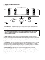
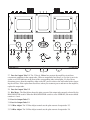
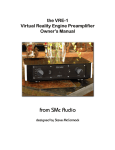
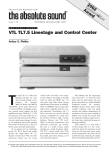
RED ROSE MUSIC
Model 5
Dual Monaural
Integrated Amplifier
Owner’s manual
RED ROSE MUSIC, INC.
RED ROSE MUSIC
Dear Music Lover,
Since 1972, I have been committed to developing state of the art audio products that enhance our
love of music.
It is clear to me that the audio world has become oriented towards complexity and mediocrity. Even
high price tags do not guarantee sonic quality or a good investment. In December of 1998, I founded
Red Rose Music to focus on a return to quality and simplicity. We nourish the love of music by
making products with exceptional qualities, by taking care of our customers, and by taking a stand in
the industry for what is right, not just expedient.
Using breakthrough technology in combination with proven principles of the past, Red Rose Music
offers more human, natural sound. In addition, we offer it at more affordable prices and in compact
packaging. The people who design and handcraft Red Rose equipment are passionate, dedicated,
gifted and committed individuals. It is my privilege to work with them.
Thank you for choosing Red Rose Music equipment. You have selected well.
–Mark Levinson, CEO
Red Rose Music
We would love to hear from you!
[email protected]
Red Rose Music
943 Madison Avenue at theWhitney Museum
New York, NY 10021
USA
Tel: 212-628-5777
Fax: 212-628-6150
E-mail: [email protected]
RED ROSE MUSIC
A Message From Victor Tiscareno:
Chief Designer, Red Rose Music
At Red Rose Music we have built our reputation and design philosophy around the use of highperformance power supplies in vacuum tube components. We believe that a good circuit can only
sound as good as its power supply. Our experience has taught us that providing the best possible
sound requires careful planning, design and execution. But maximum performance from these areas
requires meticulous attention to the power supply design for each circuit in the amplification chain.
A tightly regulated power supply can improve the sound of any audio circuit. Vacuum tube circuits
in particular operate at much higher voltages and impedances than solid-state circuits; therefore the
potential for both noise and signal corruption is greater. And it is well known that circuits with
triodes realize the greatest benefit from precision regulated, low-impedance power supplies.
Pre-amplifiers and amplifiers operate in basically the same manner: they take low-level signals and
boost them to useful levels. In a pre-amplifier, the current draw of a Class A circuit causes relatively
low fluctuations on the power supply. The power supply in a two-channel pre-amplifier must remove
the inherent noise (ripple voltage) from the incoming power source, isolate the signals from the
opposite channel, and reduce or eliminate any modulating effects between gain stages. A power
amplifier begins with the signal from the pre-amplifier stage, including all the noise produced in the
pre-amplifier. Therefore, the quality of sound produced by a power amplifier can be no better than
the quality of the signal that amplifier receives from the pre-amplifier. This is the well-known “garbage in, garbage out” principle.
Static bench measurements don’t always reflect the improvements produced by a regulated power
supply, but listening tests are extremely convincing. An improved power supply produces subjective
improvements in both noise reduction and transient signal performance.
There are three basic ways to design a power supply for an amplifier or a pre-amplifier:
1. Starting with a power transformer, feed the raw AC to a bridge rectifier, and then filter and
smooth it to an unregulated DC voltage level, using either capacitors or large inductors.
Regulation of this type of power supply is produced by the impedance of the transformer
winding and the amount of capacitance used for filtering. The unregulated voltages are split
off to various points in the circuit, where additional, localized filtering is applied in order to
isolate the gain stages from one another. Because of the relatively low cost, most amplifiers
use this kind of design.
2. The next step up in power supply sophistication is to use a single regulator that splits off DC
voltages to various points in the circuit. In most cases, a single regulated supply feeds all of
the amplifier stages, but more costly designs use separately regulated supplies at key points
in the circuit. The choice between a single supply and multiple supplies is a trade-off between cost and performance. More than 99% of all amplifier manufacturers have chosen not
to regulate the output stages of their amplifiers.
3. The best (and most expensive) design approach is to use separate regulators for the main
power supply and the gain stages, in order to isolate the circuits. This is the approach used in
Red Rose Music amplifiers and pre-amplifiers.
Of course, the design of the power supply is not the only thing that effects the sound of an amplifier.
The choice of an amplifier circuit type is also extremely important. In theory, a push-pull amplifier
circuit produces more power than a single-ended design and it cancels out even-order distortion, but
most push-pull amplifiers never reach this theoretical ideal. Although most tube amplifiers sound
better than the majority of solid state designs, they can leave some listeners unsatisfied; some members of the single-end design camp argue that push-pull designs strip away harmonic texture from the
sound they produce. Therefore, those designers have chosen to use single-end designs.
A push-pull design can fail to deliver on its promise for several reasons: our own research has indicated that non-linearity in the audio transformer, the power supply design and the phase inverter may
all contribute to less-than-accurate presentation. A gain or driver stage that does not exhibit perfect
push-pull action will cause an offset to occur in the audio transformer, which can substantially
reduce the quality of the sound. A push-pull audio transformer is supposed to be balanced to the
center-tap point where the high voltage is fed to the output tubes; but any shift in winding balance,
coupled with poor push-pull action from the driver stage, will cause distortion products to rise,
which further reduces the sound quality.
Our solution to this problem has been to use power-supply regulation at every point where there may
be potential interference from any other part of the circuit. For example, every tube and every gain
stage in our Model 1 amplifier and pre-amplifiers has its own high-voltage plate regulator, and all
the filaments are DC and fully regulated – basically, we regulate everything!
The design of the audio circuit is just as important as the power supply. We begin each product
design on a clean sheet of paper, with nothing left to chance. We analyze every element in the circuit
to find the best way to produce clean, incorruptible power and a noise-free environment for the
signal path. We select components for their contribution to the sound, not because of their audiophile
pedigrees. Every part is subjected to careful listening sessions and committee discussion before we
add it to a circuit. Because all components change their sound as they “break in”, we also check
every resistor, capacitor and tube for reliability and sound quality over the life of the product.
Red Rose Music uses only the finest custom-designed audio and power transformers. We use the
highest quality computer-grade capacitors in the high-voltage power supply, MIT® tin-foil polypropylene capacitors in the audio circuits, along with Holco® and Roederstein® resistors, Rel-Cap®
polystyrene .090-inch thick SMOBC (solder mask over bare copper) printed circuit boards, Cardas®
binding posts, Neutrik® XLR Connectors, and Hubbell® IEC 320 power connectors.
The end result of our design effort is a lower noise floor, resolution without edge, a wide deep
soundstage, and well-controlled bass reproduction.
But please listen for yourself…hearing is believing!
Model 5 Integrated Amplifier Features:
•
•
•
•
•
•
•
•
•
•
•
•
•
•
•
•
•
•
•
•
•
•
•
Selected and matched EL-34 and 12AT7 tubes
Onboard plate current meter
Switch selection of Triode or Ultralinear mode
Five line stage stereo inputs
Unbuffered line-level Tape outputs
Regulated power supply for output tubes
Separate reference supplies for high voltages
Heavy-duty power transformer with separate windings for each channel
Separate bridge rectifiers and regulators for each channel
Large wide-band audio output transformers
All transformers are electrically isolated and mechanically shock-mounted
All-aluminum laminated two-layer chassis for resonance damping
Additional internal damping material for added control of mechanical resonance
Standby mode to reduce power consumption and extend tube life
Cardas® speaker binding posts
4, 6 and 8-ohm output impedance taps for optimum speaker impedance matching
Adjustable optimized feedback for each output impedance tap
.093-inch (2.3 mm) FR-4 mil-spec printed circuit board with heavy plating, wide traces,
solder mask over bare copper, and double-sided plate-through holes
Vibration-absorbing elastomer feet
Multi-color LED status indicator
Fuses protect amplifier circuit if any tube is over current
LED indicators in tube sockets light when overcurrent fuses blow
Optional–Full cage to protect tubes
Specifications
Tubes compliment
Power output
Frequency response
Power bandwidth
Input sensitivity
Input attenuator
Input impedance
Output taps
Overall negative feedback
Hum and noise
Power requirements
AC requirements
Dimensions
Weight
Weight:shipping
2 each 12AT7 per channel
2 each EL34/6CA7 per channel
45 watts / 1 kHz / 1% THD
5 Hz to 50 kHz, -3 dB @ 1 w
16 Hz to 30 kHz, -3 dB @ 35 watts
.125V for full output, attenuator set at maximum
23 positions, 66 dB of attenuation
75k ohms
4, 6 and 8 ohms
7.5 dB
>85 dB SN Ref 1 W, no weighting
350 watts maximum
100v/120v/220~240V (CE countries set to 230V)
12.5 d x 17.0 w x 7.5 h
31.75cm x 43.18cm x 19.05 cm
54 lb (25 kg)
64 lb (29 kg)
A Tour of Your Model 5 Amplifier
Front Panel
1. Program Selector The position of the Program Selector switch specifies the currently active
program source. Each position on the Input Selector switch corresponds to a pair of input connectors
on the rear panel.
Note: In order to prevent damage to your speakers from an unexpected loud program
source, we strongly recommend that you turn the Volume Control all the way down
before you change programs.
2. Volume Control The Volume Control is a precision step attenuator switch that adjusts the
amplifier’s output volume level. Each step on the volume control increases or decreases the volume
level by 3 decibels. The lowest setting (extreme counter-clockwise) allows a very low-level signal to
pass to the speakers. To completely silence the speakers, use the Power switch to set the amplifier to
Standby mode.
3. Mode Indicator The Mode Indicator is a multi-color LED indicator. When the LED is green, the
amplifier is in ON mode and ready to operate. When the LED is red, the amplifier is in Standby
mode. When the LED is orange, the amplifier is ON and in its warmup cycle; the LED will change
color when the amplifier is ready to run. When the LED is dark, the amplifier is off.
4. Power Switch: OFF When the Power Switch is set to OFF, the amplifier is turned off.
5. Power Switch: STBY When the Power Switch is set to STBY, the amplifier is in Standby mode.
In Standby mode, the tubes receive filament voltage, and the filter capacitors maintain their charge,
but no program signal pass through the amplifier. Use Standby mode when you switch between
Ultralinear and Triode operation. The Mode Indicator LED lights in red when the amplifier is in
Standby mode.
6. Power Switch: ON The ON setting is the normal operating position. When you turn the amplifier
on, it may enter the warmup timing cycle for approximately 30 seconds while the tube filaments
reach operating temperature. During warmup, the Mode Indicator LED lights in orange. When the
amplifier is ready to operate, the Mode Indicator LED lights in green.
Rear Panel
7. Right Channel Inputs The five Right Channel input connectors accept line-level audio signals
from external program sources such as compact disc players and tuners. The amplifier plays the
program from each connector through the Right Speaker output when the Program Selector switch is
set to the position that corresponds to that connector. All five connectors are identical line-stage
inputs. The amplifier does not include a phono preamp stage; in order to play LPs or other records,
you must use an external preamplifier.
8. Tape Out (Right) The Tape Out connector is an unbuffered output that carries the currently
selected Right Channel program source at a constant level. The Volume Control setting has no effect
on the Tape Out signal.
PLEASE NOTE: If you set a recorder connected to the Tape Out connector to monitor the
recorder’s input signal, and set the amplifier to play back the program from that recorder, you
will create a feedback loop, which will drive the amplifier into oscillation, and possibly damage
your speakers. The Model 5 amplifier does not include a traditional “Tape Monitor” setting.
9. Feedback Control (Right) The Feedback Control switch is a rotary switch that sets the optimal
feedback level for speakers with different impedances. Use a small screwdriver or alignment tool to
move the red mark next to the impedance of the speaker connected to the right channel of the amplifier. If you don’t know the impedance of your speakers, consult the documentation supplied with the
speaker, ask your dealer or the speaker manufacturer, or use an ohm meter to measure the impedance. Turn the amplifier off before you adjust the Feedback Control setting.
10. Right Speaker Connectors The Right Speaker connectors are five-way binding posts. Connect
the positive (+) terminal on the speaker to the connector on the amplifier that comes closest to the
speaker’s impedance. Connect the negative (–) terminal on the speaker to the 0Ω(Common) connector. For best performance, use high-quality speaker cables.
11. Ground Switch (Right Channel) Use the two Ground Switches to eliminate hum caused by
ground loops between the amplifier and other components in your audio system. The Ground Switch
has three settings:
COMMON When the switch is set to COMMON, the signal grounds for both channels are
tied together. This setting overrides the FLOAT position of the Left Channel Ground Switch.
FLOAT When the switch is set to FLOAT, the right channel’s signal ground is isolated from
both chassis ground and left channel signal ground.
GROUND When the switch is set to GROUND, the right channel’s signal ground is shorted
to chassis ground.
12. Output Tube Operation The Output Tube Operation switch has two settings:
ULTRALINEAR When the switch is set to ULTRALINEAR, the EL-34/6CA7 output tubes
operate as pentodes. Use this setting for maximum power output.
TRIODE When the switch is set to TRIODE, the output tubes operate as triodes. This
setting provides improved audio quality (lower noise and less distortion), but it drops the
amplifier’s output power by approximately 50%, which reduces the volume at any position of
the Volume Control by about 1.5 dB.
The sonic character of the Model 5 amplifier is somewhat different in each of the two operating
modes. In general, the sound of Triode mode is more “relaxed”, with better resolution of the music’s
inner detail. In Ultralinear mode, the sound has more dynamic impact. The difference is entirely
subjective, and you may prefer different modes for different speakers, or different types of music, or
even for different recordings. We encourage you to try both settings and chose the one you prefer.
Remember to turn off the amplifier before changing the Output Tube Operation setting.
13. Ground Switch (Left Channel) Use the two Ground Switches to eliminate hum caused by
ground loops between the amplifier and other components in your audio system. The Ground Switch
has three settings:
COMMON When the switch is set to COMMON, the signal grounds for both channels are
tied together. This setting overrides the FLOAT position of the Right Channel Ground
Switch.
FLOAT When the switch is set to FLOAT, the left channel’s signal ground is isolated from
both chassis ground and right channel signal ground.
GROUND When the switch is set to GROUND, the left channel’s signal ground is shorted
to chassis ground.
Turn off the amplifier before changing the Ground Switch setting.
14. Left Speaker Connectors The Left Speaker connectors are five-way binding posts. Connect the
positive (+) terminal on the speaker to the connector on the amplifier that comes closest to the
speaker’s impedance. Connect the negative (–) terminal on the speaker to the 0Ω (Common) connector. For best performance, use high-quality speaker cables.
15. Feedback Control (Left) The Feedback Control switch is a rotary switch that sets the optimal
feedback level for speakers with different impedances. Use a small screwdriver or alignment tool to
move the red mark next to the impedance of the speaker connected to the right channel of the amplifier. If you don’t know the impedance of your speakers, consult the documentation supplied with the
speaker, ask your dealer or the speaker manufacturer, or use an ohm meter to measure the impedance. Turn the amplifier off before you adjust the Feedback Control setting.
16. Tape Out (Left) The Tape Out connector is an unbuffered output that carries the currently
selected Left Channel program source at a constant level. The Volume Control setting has no effect
on the Tape Out signal.
17. Left Channel Inputs The five Left Channel input connectors accept line-level audio signals
from external program sources such as compact disc players and tuners. The amplifier plays the
program from each connector through the Left Speaker output when the Program Selector switch is
set to the position that corresponds to that connector. All five connectors are identical line-stage
inputs. The amplifier does not include a phono preamp stage; in order to play LPs or other low-level
program sources, you must use an external preamplifier.
18. AC Power Connector The AC Power Connector is a standard IEC three-wire AC socket. The
AudioPrism HC power cable supplied with your amplifier meets our minimum performance specification, but you may improve the amplifier’s performance by replacing it with our SuperNatural™
power cord.
19. Fuse Holder The fuse holder contains two fuses. The fuse farthest from the outside of the fuse
holder protects the amplifier from AC power surges. The second fuse is a spare. To open the fuse
holder, disconnect the power cable from the amplifier, and insert the blade of a small flat-blade
screwdriver into the hole at the top of the fuse holder and turn the screwdriver. To remove the active
fuse, twist the fuse 90º out of the holder.
NOTE: Under no circumstances should you replace the power fuse with one of a higher
rating! Doing so may cause further damage to the Model 5 and will also void the warranty. In addition, your continued protection from fire or shock would be seriously compromised.
Top of Amplifier (refer to next page for illustration)
20 - 23. Line Stage Tube Sockets The four 12AT7 vacuum tubes supplied with the Model 5 amplifier fit the Line Stage Tube Sockets. Each of the tubes supplied includes a mark that identifies the
specific socket that held that tube when the amplifier was aligned at the factory.
24. BIAS MONITOR Switch The BIAS MONITOR switch selects the current use of the Bias
Meter. The V1, V2, V3 and V4 settings assign the meter to display the bias (plate current) of one of
the four EL-34/ 6CA7 output tubes. Set the switch to the OPERATE position for normal operation of
the amplifier.
25. V1 Bias Adjust The V1 Bias Adjust control sets the plate current of output tube V1. Use an
alignment tool or a small screwdriver to raise or lower the plate current.
26. V2 Bias Adjust The V2 Bias Adjust control sets the plate current of output tube V2.
27. Fuse for Output Tube V1 The 250 mA, Micro fuse protects the amplifier circuit from
overcurrent conditions in the output tubes. When an output tube fuse blows, or if a fuse is not in its
socket, a red LED indicator at the front of the corresponding tube socket lights. If a fuse blows,
disconnect power from the amplifier, either at the IEC power socket or the wall outlet before removing the old fuse. If the replacement fuse blows when you reconnect power and turn on the amplifier,
replace the output tube.
28. Fuse for Output Tube V2
29. Bias Meter The Bias Meter shows the plate current of the output tube currently selected by the
BIAS MONITOR switch. When the BIAS MONITOR switch is set to OPERATE, the meter should
remain at 0 mA.
30. Fuse for Output Tube V3
31. Fuse for Output Tube V4
32. V3 Bias Adjust The V3 Bias Adjust control sets the plate current of output tube V3.
33. V4 Bias Adjust The V4 Bias Adjust control sets the plate current of output tube V4.
34 – 37. Output Tube Sockets V1 – V4 The four EL-34/6CA7 output tubes supplied with the
amplifier fit the Output Tube Sockets. The base of each tube is marked with the socket number
where that tube was used when the amplifier was aligned at the factory. For best performance, each
tube should be used in the corresponding socket. The front of each tube socket has a red LED indicator that lights when the fuse for that socket has blown, or the fuse is not in its socket.
38. Mounting holes for Transformer Cover or optional full Cage Cover. The optional full Cage
Cover replaces the standard Transformer Cover. To mount the cage, push gently on both sides and
insert the mounting pins into the four holes. To remove the cage, lift both sides making sure that you
clear the tubes and transformers. *The full cage is optional and will replace the transformer cover
when it is in use.
Installing Your Model 5 Amplifier
Please follow this installation procedure when you place the amplifier into service. The time you
invest in proper installation and bias alignment will reward you with many hours of fine performance.
1. Confirm that the Power switch is set to OFF. Don’t try to install the amplifier with the Power
switch in the STBY or ON position.
2. Confirm that the AC power cord is not connected to the amplifier. Place both ground
switches in the GROUND position
3. Consult the specifications for your speaker to find their nominal impedance.
4. Use a small flat-blade screwdriver to move the red marks on the right and left Feedback
Controls to the correct impedance setting for your speakers.
5. Set the output tube operation switch to ultralinear. After installtion you may want to experiment with both settings to choose the one that sounds better with your speakers and program
sources.
6. Place the amplifier in the location where it will operate.
7. Connect the speaker cables between the amplifier and your speakers. The Model 5 is a non-inverting amplifier, so the speaker
cables should be connected with absolute polarity. Positive (+)
from the Model 5’s amplifier output binding post to the positive
(+) speaker binding post and negative (0Ω) to the negative (–)
speaker binding post.
Note: For best performance, always use the output impedance
closest to the speaker manufacturer’s impedance rating, i.e. 4 ohms to 4 ohms. Be
careful to only connect the speaker wiring between the negative lead (0 Ω) and a single
(+) 6Ω positive output impedance (as one example). Avoid connecting the speaker cable
connectors between the (+) 6Ω and (+) 8Ω taps or the (+) 6Ω and the (+) 4Ω which will
cause the amplifier to malfunction.
For best performance, use quality speaker cables.
May we suggest you use our Red Rose Music cables as a good system match.
8. Place Transformer cover after installing the four retaining pins through the threaded inserts
located on the bottom. The (optional) Full Cage Cover is shipped separately.
9. Aligning the pins to the pattern in sockets (Note: The space in the tube and socket), Insert
the four 12AT7 tubes into their sockets. When they are firmly seated, wipe each tube with a
clean soft cotton cloth to remove fingerprints and oils transferred from your fingers, which
can reduce the life of the tubes. Please locate the cotton gloves to minimze contact with the
tube’s glass envelope.
10. Insert each of the output tubes into the socket with the number that matches the number
marked on the tube. Carefully align the key in the base of the tube to the keyway in the
socket. Take care to avoid damaging the positioning key on the base of each tube. If you did
not use the cotton gloves, wipe the glass part of each tube with a clean soft cotton cloth.
11. Install interconnect cables between the amplifier and your high-level program sources. All
five pairs of inputs are identical high-level analog channels. If you want to use the amplifier
with a turntable or other low-level program source, you must use an external preamplifier
stage. If you are using a digital program source, you must use an external digital-to-analog
converter. CD players have self contained digital-to-analog converters.
Note: You have been supplied eight RCA shorting plugs (4 per channel) to use in
unused source inputs. However, do not short the tape loop output RCA.
12. If you want to record music as you play it through the amplifier, install interconnect cables
between the amplifier’s TAPE OUT connectors and the recorder’s analog inputs.
13. Plug the power cord into the amplifier, and then into an AC power outlet. Do not use a
convenience outlet on another component; plug the power cord directly into a wall outlet, or
use a power conditioner or power strip.
14. Turn the volume control down. Turn the Power switch to ON. When the tube filaments reach
their operating temperature, the AC mains power control circuit will automatically power up
to ON and change the LED indicator above the Volume Control from orange to green.
15. Red Rose Music has tested and adjusted the plate current settings of your amplifier before it
left the factory, and most Red Rose Music dealers put the amplifier through an additional
“burn-in” test before they sell it. Therefore, the bias settings for the four output tubes should
be very close to their correct values and should not require further adjustment. However, we
still recommend that your check the plate current adjustment for each output tube after
installing the amplifier.
On a new installation, carefully monitor the bias monitor for signs of a malfunctioning
tube. A sharp increase in plate current over the 45 ~ 50 ma range should monitored. A tube
showing excessive plate current will require replacing it with a new tube. Your Model 5 has
been supplied with a spare output and input tube in the event a replacement becomes
necessary. Please review the section “Replacing the output tubes” for ultralinear biasing
information.
With no audio program playing through the amplifier and after the amplifier has been running for about five minutes in ULTRALINEAR mode, use the BIAS MONITOR selector
switch to measure the plate current of each output tube. The plate current of each tube should
be 45 mA ±4mA. If the meter shows that a tube has a plate current out of that range, use the
Bias Adjust trim pot for that tube to increase or decrease the plate current. Move the BIAS
MONITOR switch to OPERATE when you are not measuring bias.
16. With no program playing, listen to your speakers. If you hear a loud hum, turn off the amplifier, unplug and reconnect the interconnect cables at both ends and turn the amplifier back
on. If the hum is still there, try different settings of the two Ground Switches until you find
the combination that produces the least hum. You should be able to achieve an extremely low
noise floor with the Model 5. However, some sources will pass through more power supply
noise than others. If that doesn’t fix the problem, try replacing the interconnect cables. Some
cables have high-resistance shields that can cause ground loops.
If none of these steps eliminates the hum, consult your dealer.
17. After about thirty minutes of operation, check the plate current of each output tube again, in
Ultralinear mode with no audio signal present.
18. If you want to use the amplifier in Triode mode, turn it off and change the position of the
Output Tube Setting switch.
Note: Bias current in triode mode will indicate a lower bias current than Ultra-linear,
approximately 2 ma lower. This is normal and we would advise against adjusting
the bias to compensate for this change.
19. If you purchased the optional Full Cage Cover, it snaps onto the top of the Model 5’s top
panel using the guide pins provided with the cover. See No. 38 on top panel illustration.
Day-to-Day Operation
To turn on the amplifier, move the Power switch from OFF or STBY to ON and wait for the front
panel LED to turn green. At the end of a listening session, move the Power switch to STBY to
extend the life of the tubes and maintain thermal stabilization. When you switch from STBY to ON,
there is no thirty second waiting period. Standby is indicated by a red LED.
In the event that the power is disrupted due to a power failure or accidental power cord disconnection, the Model 5 will default to the OFF power condition and go through a complete thirty second
timing cycle before returning to ON. When the amplifier has been in the OFF position and is then
moved to the ON position, the LED indicator will light in orange throughout the timing cycle and
then light in green in the ON position. The orange LED will only appear from a power ON
intialization for the duration of the timing cycle and at no other time.
Note: In order to avoid transient damage to your speakers, turn the volume control all the way
down when you change program sources.
If you don’t expect to use your audio system again within 24 hours, turn off the amplifier.
Always disconnect power from the Model 5 before removing tubes. Serious damage may occur to
the Model 5 if any tubes are removed while the power is ON.
Do not overdrive the amplifier. Excessive input levels will drive the amplifier into distortion, reduce
the life of the tubes and may damage the speakers.
Replacing the Output Tubes
There are two possible reasons for replacing the tubes in your amplifier. Either the tubes supplied
with the amplifier have worn out, or you want to experiment with a different brand of tubes.
The tubes supplied with your amplifier will meet or exceed our minimum performance specifications, but “super premium” tubes might produce a subjective improvement in the sound produced by
the amplifier. All four output tubes should be the same brand, but it is not necessary to use premium
“matched sets,” because the on-board bias adjustment allows you to match any set of four tubes.
When you replace the output tubes, we recommend that you replace the input tubes at the same time.
The tubes supplied with your amplifier should operate for at least 10,000 hours. As a tube ages, the
plate current will drop, so it will become necessary to return the plate current back to 45 mA by
turning the bias control clockwise. If the bias setting is advanced clockwise significantly over the
original setting or that it can no longer be adjusted, it may be indication that you should replace the
tubes with a fresh set of vacuum tubes.
Red Rose Music can supply replacement matched tubes at a competitive price. You may order new
tubes from your dealer, or directly from Red Rose Music.
Follow these steps to replace the output tubes:
1.
2.
3.
4.
5.
6.
7.
Turn off the amplifier.
Disconnect the power cord from the amplifier.
When they are cool to the touch, remove the old tubes.
Insert the new tubes into the sockets
Use a clean soft cotton cloth to wipe the glass parts of each tube.
Move the BIAS MONITOR switch to V1.
Use a small screwdriver or an alignment tool to turn all four Bias Adjust controls counterclockwise all the way to the stop.
8. Connect the power cord and turn on the amplifier.
9. Wait five minutes for the tubes to warm up.
10. Turn the V1 Bias Adjust control clockwise to set the plate current to 45 mA.
11. Move the BIAS MONITOR switch to V2 and set the plate current to 45 mA
12. Repeat the process for the other two output tubes.
13. Recheck each tube and again after an hour.
After all four tubes are aligned, you should be able to move the BIAS MONITOR switch between V1 and V2, and between V3 and V4 with little or no obvious meter movement.
Safety Instructions
As with any sensitive electronic equipment, make sure that the Model 5’s location is out the reach of
small children or pets. Never place electronic equipment in a location that exposes it to potential
damage by foot traffic, food or liquids.
Never place the Model 5 in a location where items from a higher shelf could fall and damage the
Model 5. Never operate the Model 5 if it is visibly damaged. If the Model 5 inadvertantly becomes
damaged, disconnect from AC power at the wall outlet and let it sit for 5 minutes before touching it.
If you are unsure of the malfunction, please read the troubleshooting guide. Your dealer or agent
should also be contacted for their advice and service before reconnecting the Model 5 to AC power.
Water and moisture: This product should never be used near water. To prevent fire or a shock
hazard, do not expose the Model 5 to rain or moisture. The Model 5 is designed for indoor use only.
Never use any liquids in and around the Model 5 that may run into the chassis or onto live circuits.
Heat: Place Model 5 should be located in a cool, dry location. Keep away from heat sources such as
heat registers, stoves or other sources that produce heat. Never block the cooling vents in, around
and under the Model 5’s chassis. Never place a cover that may hold heat in and overheat the Model
5 causing damage.
Voltage ratings: This product should be connected to a power source of the proper rated voltage.
The correct voltage rating for the Model 5 is located on the rear panel near the AC power connector.
It should never be operated above or below the designated voltage rating.
Safety ground: Never lift or defeat the safety ground connection between the power cord and wall
outlet. A shock or fire hazard is present when this safety feature is disabled.
No user serviceable parts inside. Never operate the Model 5 inverted or with the bottom inspection
plate removed. A shock hazard is present when the covers removed.
Troubleshooting guide:
Symptom: No audio, tubes and front panel LED don’t light.
Confirm that the AC power cord is firmly connected at both ends.
If the amplifier is plugged into a power strip or a power conditioner, confirm that the power switch is
on.
Use a lamp or other small electrical device to confirm that there is AC power at the outlet. If the
lamp does not light, check the fuse box or circuit breaker.
Remove the power cord from the amplifier, open the fuse holder, and inspect the fuse. If it has
blown, replace it with the spare. If the fuse blows again, contact your dealer or Red Rose Music’s
customer service department.
Symptom: No audio, tubes and LED light
Make sure the Power switch is not set to STBY.
Make sure the program source is turned on and producing a signal. Confirm that the cables from the
source component to the amplifier are connected at both ends.
Confirm that the speaker cables are connected to the amplifier and the speakers.
Use the BIAS MONITOR switch to check the plate current of the four output tubes. If the meter
shows low plate current for one or more tubes, and you are unable to use the Bias Adjust control to
bring the plate current up to the correct value, replace all four output tubes.
If the meter shows no plate current for a single tube, or if the red LED in one of the output tube
sockets lights, disconnect power to the amplifier and replace the fuse for that tube socket.
Symptom: Distorted audio
Make sure the Power switch in set to ON rather than STBY
Try changing to a different program source. If the distortion only exists on one source, check the
component that produces that signal. If an FM signal is distorted, try listening to the same station on
another radio.
If the distortion exists on more than one source, check the bias level of all four output tubes. If one
or more tube’s plate current is out of the normal range (45 mA ±4 mA), use the Bias Adjust controls
to set the correct bias.
Check the 12AT7 tubes. Your Red Rose Music dealer can test the tubes for you. Replace them if
necessary.
If the amplifier is in Triode mode, reduce the volume and see if the distortion is only present during
loud passages. You may be overdriving the amplifier. Switch to Ultralinear mode and try again.
Service and Technical Support
If your amplifier requires service, you may either consult your Red Rose Music dealer, or send it
directly to Red Rose Music.
If you choose to return it to the factory, please call us first. If we can diagnose the problem by telephone, we may be able to tell you how to fix it without the inconvenience and expense of packing
and shipping the amplifier. Please do not send us your amplifier until we give you a return authorization.
You can contact Red Rose Music at this address:
Red Rose Music
2729 152nd Avenue NE
Redmond, Washington 98052
Voice: 425-869-8482
Fax: 425-869-1873
e-mail: [email protected]
Please use the original packing materials when you ship your amplifier to us. If you did not save the
original box, let us know when you request a return authorization, and we will send you a replacement. We must charge for the replacement box at our cost of materials plus shipping.
Limited Warranty
Your Red Rose Music Model 5 integrated amplifier is warranted to be free of manufacturing defects
for five years from the date of purchase. Red Rose Music will at its’ option repair or replace defective components free of charge during this period.
The vacuum tubes are separately warranted to be free of defects for a period of one year from the
date of purchase.
This warranty is void if the Model 5 has been altered or modified in any way by anyone other than
Red Rose Music or an authorized Red Rose Music service representative.
This warranty does not cover normal maintenance to the product. Red Rose Music is not responsible
for consequential or indirect damage resulting from the use or operation of this product, or from any
breach of this warranty or any implied warranty relating to this product. The warranty does not
include damage caused by circumstances beyond the control of Red Rose Music, Inc. including, but
not limited to, fire or other casualty, accident, neglect, abuse or abnormal use.
Red Rose Music cannot be held responsible for any loss or damage caused in transit.
The product must be prepaid and insured to Red Rose Music. To facilitate servicing, all products
require a return authorization number before shipment to our warranty station.
The Red Rose Music Warranty starts with the date of purchase and applies only to the original
purchaser.