1
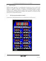
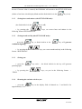
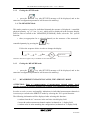
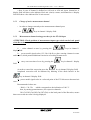
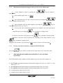
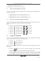
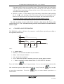
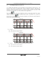
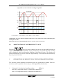
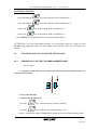
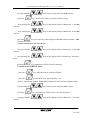
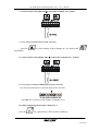
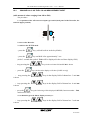
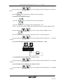
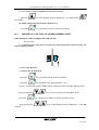
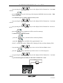
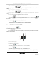
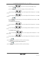
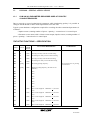
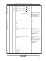
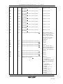
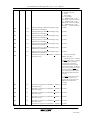
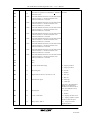
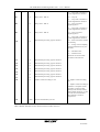
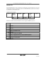
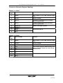
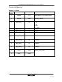
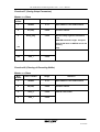
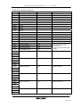
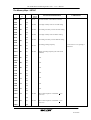
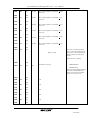
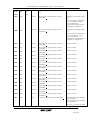
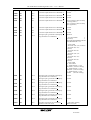
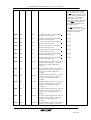
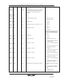
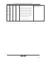
THE DLM-080 FUTURE DIGITAL RECORDER –
USER’S MANUAL
VERSION 1.1
Sp. z o.o. [Ltd.]
41-250 Czeladź ul. Wojkowicka 21, Poland
Tel. +48 (32) 763 77 77, 763 78 15÷18
Fax.:+48(32) 763 – 75 - 94
www.mikster.com [email protected]
(26.11.2004)
The DLM-080 FUTURE Digital Recorder – User’s Manual
TABLE OF CONTENTS
TABLE OF CONTENTS ............................................................................................................................. 2
1. APPLICATIONS ................................................................................................................................. 4
2. THE DLM-080 RECORDER CONSOLE ............................................................................................ 4
3. THE DLM-080 RECORDER CONFIGURATION.............................................................................. 5
3.1
SPECIAL FUNCTIONS (RECORDER CONFIGURATION)....................................................... 5
3.1.1
SPECIFICATION OF SPECIAL FUNCTIONS........................................................................ 6
3.2
REAL-TIME CLOCK SETTING (THE SET CLOCK MODE)...................................................... 6
3.3
MODIFICATION OF PARAMETERS IN THE SETUP MEMORY (THE SETUP MODE) ......... 8
3.5
MEASUREMENT CHANNEL SCALING, THE -SERVICE- MODE............................................ 9
4. THE DLM-080 RECORDER MEASUREMENT AND CONTROL CHANNELS ........................... 11
4.1
THE PT-100 MEASUREMENT CHANNEL ............................................................................... 12
4.2
THE 0..20 (4..20) mA MEASUREMENT CHANNEL ................................................................. 12
4.3
CHANNEL AS TIME-METER .................................................................................................... 12
4.4
CHANNEL AS MULTIVIBRATOR ............................................................................................. 13
4.5
CONTROLLER RELAY OUTPUTS............................................................................................ 14
4.6
MODIFICATION OF CONTROLLER SET VALUE .................................................................. 15
5. HUMIDITY MEASUREMENT USING THE PSYCHROMETER METHOD................................. 15
6. ALARMS ........................................................................................................................................... 17
7. CO-OPERATION OF THE RECORDER WITH MASTER COMPUTER (RS-485)........................ 17
8. PRINTING OF RECORDS ................................................................................................................ 17
9. KEYBOARD INTERLOCK .............................................................................................................. 18
10.
EXAMPLES HOW TO CONFIGURE THE DLM-080 ................................................................. 19
10.1 CHANNEL No. 5 AS THE PT100 MEASUREMENT INPUT..................................................... 19
10.2 CHANNEL No. 8 AS THE 0..20 mA MEASUREMENT INPUT ................................................. 22
10.3 CHANNEL No. 2 AS THE 4..20 mA MEASUREMENT INPUT ................................................. 24
10.4 CHANNEL No.1 AS HOUR-METER.......................................................................................... 26
11.
DLM-080 – SPECIAL APPLICATIONS....................................................................................... 28
11.1 DLM-080 AS PARAMETER RECORDER USED AT POULTRY SLAUGHTERHOUSES. ....... 28
THE SETUP FUNCTIONS – SPECIFICATION....................................................................................... 28
MODBUS RTU.......................................................................................................................................... 34
FUNCTION 4 (RECORDER REGISTER READING)............................................................................................ 34
FUNCTION 65 (REAL-TIME CLOCK – RTC SETTING).................................................................................. 35
FUNCTION 66 (MEASURE) ........................................................................................................................... 37
FUNCTION 67 (SAVING SETUP PARAMETERS) ............................................................................................. 38
FUNCTION 68 (CLEARING OF RECORDING BUFFER)..................................................................................... 38
THE MEMORY MAP : MULTIPURPOSE REGISTERS ....................................................................................... 39
THE MEMORY MAP: SETUP ...................................................................................................................... 41
2
26.11.2004
The DLM-080 FUTURE Digital Recorder – User’s Manual
TECHNICAL DATA
DIMENSIONS:
•
assembly hole size: 142+1mm X 237+1mm
•
assembly depth including terminals: 55mm
•
outside dimensions: 265x152
WEIGHT:
•
•
1250 g (RECORDER)
800 g (TRANSFORMER)
POWER SUPPLY:
•
~24V(AC), 220-24V TRANSFORMER INCLUDED IN THE SET
STRUCTURE:
•
SINGLE ELEMENT, “FRONT PANEL”-TYPE
PROTECTION CLASS: (ACCORDING TO IEC 529)
•
from terminal side: IP 20
•
from front side: IP 65
HUMIDITY:
•
0..75 % (OF RELATIVE HUMIDITY)
TEMPERATURE:
•
ambient: -20..+70 °C
•
working: 0..+60 °C
OUTPUTS:
•
•
max 12 RELAY OUTPUTS 250V,
TOTAL
CURRENT INTENSITY OF CONNECTED RELAYS: Icmax=4A
4 TRANSISTOR OUTPUTS, Iomax=100mA (optionally)
INPUTS:
• 8 MEASUREMENT CHANNELS WITH INPUT
- PT-100 - MEASUREMENT RANGE FROM -100.0°C TO +400.0°C,
RESOLUTION (ACCURACY) 0.1°C
- CURRENT SIGNAL: 0..20 mA , 4..20 mA (RANGE: 3 DIGITS)
• BINARY CONTROL INPUT: 0-220V AC (0-24 V AC)
DIGITAL COMMUNICATION:
• SERIAL PORT
1xRS-232 (PRINTER)
1xRS-485 (MASTER COMPUTER)
RECORDING MEMORY:
• 2000 samples / channel for RAM memory = 32KB (STANDARD)
3
26.11.2004
The DLM-080 FUTURE Digital Recorder – User’s Manual
1.
APPLICATIONS
DLM-080 Digital Recorder is a multifunctional microprocessor device used for the
purposes of recording, control and visualisation of manufacturing processes in many
branches of industry. In particular it is designed to co-operate with master computer
(software for PC computers delivered together with the recorder), which also allows
performing analysis of registered data in graphic form. Moreover, it is possible to make
printouts in for documentation purposes.
2.
THE DLM-080 RECORDER CONSOLE
All operations of the DLM-080 Recorder are initiated from its console (Fig.1).
1
3
5
7
%
bar
%
bar
%
bar
%
bar
2
%
bar
4
%
bar
6
%
bar
8
%
bar
4
26.11.2004
The DLM-080 FUTURE Digital Recorder – User’s Manual
Keys on the console are arranged in the following keypads :
• the status block -1- with the following functions :
• real-time display 1.1
• function keys 1.2 with signal diodes 1.3
• parameter value increase / decrease keys 2.5
• 8 measurement channel status keypads -2- with the following functions :
• read out / set value display 2.1
• display field showing the measure of a physical value being measured 2.3
• function keys with signal diodes 2.4
• parameter value increasing / lowering keys 2.5
All information as regards working mode of the DLM-080 Recorder (values of preset and
read out parameters, equipment ON / OFF signalling, etc.) is displayed on digital displays
and by diodes.
It is necessary to press proper keys in order to save data in the DLM-080 Recorder
memory, correct data and call required controller functions.
3.
THE DLM-080 RECORDER CONFIGURATION
Immediately after turning the Recorder on all of its displays will become active, and then,
after approximately 3 sec. the Recorder will switch to the working mode and execute
operations according to preset configuration.
In order to ensure that the Recorder work complies with user’s guidelines, the following
configuration operations must be carried out :
• set (check) the real-time clock readout
(the SET CLOCK mode)
• set (check) data setting in the SETUP memory (the SETUP mode)
• scale (check) readouts on measurement channels (the SERVICE [SERWIS] mode)
• set (check) displaying of dimension of measured physical values (the DIMENSION
[WYMIAR] mode)
3.1
SPECIAL FUNCTIONS (RECORDER CONFIGURATION)
In order to modify / initiate settings of the Recorder configuration parameters, whole
range of special functions has been introduced. They permit to carry out the abovementioned operations.
Special functions will be available after carrying out of the following steps :
5
26.11.2004
The DLM-080 FUTURE Digital Recorder – User’s Manual
- press the
key (a diode built-in in the key blinks)
- press the
key and hold it for approximately 3 sec.
After 3 seconds the symbol F-00 will be displayed in the real-time display field.
At this moment enter number of a special function by pressing the
in the real-time display field.
Accept the selected special function by pressing the
3.1.1
3.2
keys
key.
SPECIFICATION OF SPECIAL FUNCTIONS
F00
- switches to the SETUP mode
F01
- switches to the WYMIAR [DIMENSION] mode
F02
- switches to the SERVICE mode
F03
- free
F04
- switches to the SET-CLOCK mode
F05
- program version
F06-F98
- free
F99
- clears recording buffer
REAL-TIME CLOCK SETTING (THE SET CLOCK MODE)
F04 SPECIAL FUNCTION
The unit will switch to the SET CLOCK mode after selecting the F04 special function.
The following will be displayed after selecting this function:
• word CODE in time display field
• words SET UP in channel 1 and 2 display field
keys in channel 3 and 4 display field,
At this moment, by pressing the
enter access code necessary for setting the clock parameters (standard code is: 111 111 ).
Accept set values by pressing the
key.
6
26.11.2004
The DLM-080 FUTURE Digital Recorder – User’s Manual
In case if correct value is entered, the DLM-080 will switch to the SET-CLOCK mode
(diodes of real-time clock display blinks and the diode built-in in the
3.2.1
key is on).
Setting hours and minutes (the SET-CLOCK mode)
(the diode built-in in the
key is off)
• by pressing the
following format: HOUR:MINUTE.
3.2.2
keys, set correct hour and minute in the
Setting month and day (the SET-CLOCK mode)
- press the
continuous lighting)
• by pressing the
format: MONTH:DAY.
3.2.3
key (a diode built-in in the
key will generate
keys, set correct month and day in the following
Setting year
• press the
pulsating light.
• by pressing the
:YEAR.
3.2.4
key twice – the diode built-in in the key will generate
keys, set year in the following format: --
Resetting the real-time clock to zero
press the
approximately 3 sec.
•
key in the display field of channel no. 3 and hold it for
7
26.11.2004
The DLM-080 FUTURE Digital Recorder – User’s Manual
3.3
MODIFICATION OF PARAMETERS IN THE SETUP MEMORY (THE
SETUP MODE)
The SETUP mode permits to edit the DLM-080 configuration parameters (as described in
Table 1).
The device will switch to the SET-UP mode after selecting the F00 special function. The
following will be displayed after selecting this function:
• word CODE in time display field
• words SET UP in channel 1 and 2 display field
• number 000 in channel 3 display field, and number 000 in channel 4 field
At this moment, by pressing the
keys in channel 3 and 4 display field,
enter access code to the SETUP memory (standard code is: 888 888).
Accept set values by pressing the
key.
In case if correct value is entered, the DLM-080 switches to the SETUP mode.
Word SETUP will be displayed, and:
• SETUP function number in channel 3 display field,
• SETUP value number in channel 4 display field.
Then take these steps:
• in order to modify function number press the
keys in channel 3 display field,
• in order to modify function value press the
keys in channel 3 display field.
3.3.1
SET UP memory reset and setting of initial parameters
In order to initialise the DLM-080 and reset the recording memory, take the following
steps (while remaining in the SETUP mode):
• press the
key and hold it until the 00:00 symbol is shown on the realtime display; execution of this operation results in resetting of all configuration values, the
recording memory and preset standard values of the SETUP function.
8
26.11.2004
The DLM-080 FUTURE Digital Recorder – User’s Manual
3.3.2
Exiting the SETUP mode
• press the
key (the SET EEP message will be displayed, and at the
same time configuration parameters will be stored in memory).
3.4 The MEASURE Mode
This mode permits to preset for individual channels the measure of displayed / controlled
physical quantity, e.g. (°C, bar, %, etc.), which will be displayed in the measure display
field. In order to switch to the MEASURE [WYMIAR] mode, select the F01 special
function:
• then (as appropriate for a selected channel) set the measure of the measured /
key.
controlled quantity by pressing the
Follow the sequence below in order to change the display
9 10
4
DISPLAY OFF
5
6
Bar
3
%
2
°C
8
12 1
11
7
Attention! The above applies only to standard version of the Recorder.
3.4.1
Exiting the MEASURE mode
• press the
key (the SET EEP message will be displayed, and at the
same time configuration parameters will be stored in memory).
3.5
MEASUREMENT CHANNEL SCALING, THE -SERVICE- MODE
ATTENTION: Prior to commencement of measurement channel tuning, check
whether location of switches defining type of input is in compliance with guidelines...!
In order to scale (set zero and amplify) indications in individual measurement channels it
is necessary to switch to the SERVICE mode by selecting the F02 special function.
The following information will be displayed after selecting this function :
• readout from the AC converter in the real-time clock display field
• letters ch. and measurement channel number in channel no. 1 display field
• readout value in units matching the configuration (in channel no. 2 display field)
9
26.11.2004
The DLM-080 FUTURE Digital Recorder – User’s Manual
• then, in case if channel is defined as 0.20 mA or 4.20 mA input, channel no. 4
display field will show value indicated for 0 mA (4 mA) current, and channel no. 6 display
field will show value indicated for 20 mA current.
3.5.1
Change of active measurement channel
•
in order to change currently active measurement channel press
the
3.5.2
keys in channel 1 display field.
Measurement channel tuning procedure for the PT-100 input.
ATTENTION: Check position of measurement input type switch on the back panel
of the Recorder.
1 - select channel to tune by pressing the
display field.
keys in channel 1
2 - preset model signal value (0°C; Ro=100 Ω) or place sensing element in water
and ice mix, which permits additional correction of sensing element error.
3 - carry out correction of zero by pressing the
key in channel 1 display
field.
(in order to cancel the correction press the
key in channel 2 display field)
completed correction will be indicated by blinking of the diode built-in in the
key in channel 2 display field.
4 - preset model signal value in a selected point of the PT-100 sensor characteristic
curve.
Recommended values are:
- R100 = 138.5 Ω
- which corresponds to the indication of 100 °C
then, by turning potentiometers (for respective channels
Ch1,Ch2,Ch3,Ch4,Ch5,Ch6,Ch7,Ch8) on the back panel of the Recorder, ensure
that correct read out value is being displayed.
10
26.11.2004
The DLM-080 FUTURE Digital Recorder – User’s Manual
3.5.3
Measurement channel tuning procedure for the 0..20,4..20mA input
1 - select channel to tune by pressing the
display field.
keys in channel 1
2 - preset model signal value, e.g. 20mA
3 - enter indicated value for 0 mA (4 mA) current by pressing the
keys in channel 4 display field.
4 - enter indicated value for model signal by pressing the
channel 6 display field (e.g. 20 mA )
keys in
5 - as soon as the above-mentioned operations are complete, carry out correction of
amplification by pressing the
key in channel 2 display field.
(in order to cancel the correction press the
key in channel 2 display field)
completed correction will be indicated by blinking of the diode built-in in the
key in channel 2 display field.
Attention ! Do not carry out correction of zero for the 0..20 mA, 4..20 mA input !
3.5.3
Saving corrections in memory, exiting the SERVICE mode
Press the
4.
key in order to exit the service mode and to save correction value.
THE DLM-080 RECORDER MEASUREMENT AND CONTROL
CHANNELS
The DLM-080 Recorder enables to define channel type for each of the channels as:
a) the PT-100 measurement channel (measurement range from -99.9 to +399.9° C, scale
interval 0.1 ° C)
b) the 0..20 mA measurement channel (measurement range from -99 to 999)
c) the 4..20 mA measurement channel (measurement range from -99 to 999)
d) a second-meter (range from 0 to 999)
e) a minute-meter (range from 0 to 999)
11
26.11.2004
The DLM-080 FUTURE Digital Recorder – User’s Manual
f)
an hour-meter (range from 0 to 999)
g) multivibrator (second or minute or hour base)
4.1
THE PT-100 MEASUREMENT CHANNEL
In case if a measurement channel is defined as PT-100, readout values will be displayed in
a dynamic way, that is:
•
within range from -99.9 to -10.0 with accuracy of 1 °C
•
within range from -9.9 to +99.9 with accuracy of 0.1 °C
•
within range from +100.0 to +399.9 with accuracy of 1 °C
4.2
THE 0..20 (4..20) mA MEASUREMENT CHANNEL
In case if a measurement channel is defined as 0..20 (4..20) mA, readout values will be
displayed according to the value of the F54-F61(SETUP) function.
that is:
•
if F54-F61 = 3, then display range is 0.00 to 9.99 (0..20 mA)
•
if F54-F61 = 4 , then display range is 00.0 to 99.9 (0..20 mA)
•
if F54-F61 = 5 , then display range is 000 to 999 (0..20 mA)
•
if F54-F61 = 6 , then display range is 0.00 to 9.99 (4..20 mA)
•
if F54-F61 = 7 , then display range is 00.0 to 99.9 (4..20 mA)
•
if F54-F61 = 8 , then display range is 000 to 999 (4..20 mA)
4.3
CHANNEL AS TIME-METER
In case if a measurement channel is defined as time-meter, then method of time metering
will be defined in the F38-F40 (SETUP) functions, that is:
•
if F54-F61 = 11 , then second-meter
•
if F54-F61 = 12 , then minute-meter
•
if F54-F61 = 13 , then hour-meter
Moreover, it is necessary to define in the F62-F69 functions the method for time-meter
release, that is:
•
F62-F69 = 0 time-meter reset, and it is released “manually” after pressing and
holding the
•
key (for proper channel) for approximately 2[s].
F62-F69 = 1 then, if Tini contact closed, time-meter counts down until reaching
the set value, if time-meter reaches the set value and Tini contact opens, then the
12
26.11.2004
The DLM-080 FUTURE Digital Recorder – User’s Manual
time-meter will be reset to zero and as soon as Tini contact closes the count down
will be repeated, if the time-meter does not reach the set value and Tini contact
will open, time count down will stop and as soon as Tini contact closes the count
down will be further repeated
• F62-F69 = 2 then - if Tini contact closed, time-meter counts down until reaching
the set value – each opening of the Tini contact will result in resetting the timemeter to zero and as soon as Tini contact closes again, the count down will go on
ATTENTION: Reaction to change of Tini contact state takes approximately 3 seconds !
In order to connect Tini contact follow the procedure described on the DLM-080 back panel!
In order to ensure correct work of the channel as time-meter, the To(n) value
saved in the F14 – F21 cells and referring to work of the channel as a multivibrator
must be equal.
4.4
CHANNEL AS MULTIVIBRATOR
The DLM-080 enables to declare relay output as a multivibrator operating according to
the algorithm shown below.
Prog(n)
Zał
Wył
Zał
Re(n)
Wył
Tz(n)
To(n)
where:
•
n – channel number
•
PROG(n) – state of diode in the PROG key for channel n
•
RE(n) – state of relay for channel n
•
tz(n) – preset time for channel n
•
To(n) – multivibrator period for channel n given in the F14-F21 SETUP functions
•
τ - time in compliance with definition in the F14-F21 SETUP functions
Press and hold the
key for approximately 3 sec. to reset time-meter and start the
time count-down process (diode built-in in the key is on). Press the
to stop time count-down.
multivibrator.
Press the
key in order
key to restart channel operation as a
13
26.11.2004
The DLM-080 FUTURE Digital Recorder – User’s Manual
4.5
CONTROLLER RELAY OUTPUTS
As a standard the DLM-080 uses the algorithm of on-off controller with hysteresis. The
hysteresis value must be specified in the F14-F29 (SETUP) functions. Depending on
parameter setting in functions F30-F37 it is possible to define controller relay state as NR
(normally open, algorithm 1) or NZ (normally closed, algorithm 2).
Press the
key (for proper channel) in order to ensure that control for a given
channel is carried out according to setting of the set value – the diode is on. In case if a
key (for proper channel) is off, then the control channel is
diode built-in in the
blocked and controller relay is open.
ALGORITHM 1
Hg
Wz
Hd
Zał
Wył
Wz – set value
Hg – “upper” hysteresis (F30-F45, SETUP)
Hd – “lower” hysteresis (F30-F45, SETUP)
ALGORITHM 2
Hg
Wz
Hd
Zał
Wył
Wz – set value
Hg – “upper” hysteresis (F14-F29, SETUP)
Hd – “lower” hysteresis (F14-F29, SETUP)
14
26.11.2004
The DLM-080 FUTURE Digital Recorder – User’s Manual
(Algorithm 3) 3-state controller according to algorithm
ALGORITHM 3
Hg
Wz
Hd
ZaŁ
REL1
WyŁ
ZaŁ
REL9*
WyŁ
* for F46 Æ REL9 ; for F47 Æ REL10 ; for F48 Æ REL11 ; for F49 Æ REL12
ATTENTION! In case if channel is defined as time-meter, relay contact state changes immediately after
reaching the set value.
Blinking message in the MEASURE field indicates controller contact closed state!
4.6
MODIFICATION OF CONTROLLER SET VALUE
Press the
keys (for proper channel) in order to set and modify already set
values for individual control channels. If any of these keys is pressed once, the set value
will be displayed, which is indicated by blinking of the displayed value. The display will
return automatically to read out value after approximately 2 seconds from the moment any
key was pressed last time.
5.
HUMIDITY MEASUREMENT USING THE PSYCHROMETER METHOD
The Recorder permits humidity measurement using the psychrometer method. However,
in order to make it possible it is necessary to follow guidelines listed below:
1.
if channel 1 is declared as humidity readout,
(F54 = 1)
then “dry” temperature sensor is connected to channel no. 1
and “wet” temperature sensor is connected to channel no. 2
15
26.11.2004
The DLM-080 FUTURE Digital Recorder – User’s Manual
2.
if channel 1 is declared as humidity readout,
(F55 = 1)
then “wet” temperature sensor is connected to channel no. 2
and “dry” temperature sensor is connected to channel no. 1
3.
if channel 1 is declared as humidity readout,
(F56 = 1)
then “dry” temperature sensor is connected to channel no. 3
and “wet” temperature sensor is connected to channel no. 4
4.
if channel 1 is declared as humidity readout,
(F57 = 1)
then “wet” temperature sensor is connected to channel no. 4
and “dry” temperature sensor is connected to channel no. 3
5.
if channel 1 is declared as humidity readout,
(F58 = 1)
then “dry” temperature sensor is connected to channel no. 5
and “wet” temperature sensor is connected to channel no. 6
6.
if channel 1 is declared as humidity readout,
(F59 = 1)
then “wet” temperature sensor is connected to channel no. 6
and “dry” temperature sensor is connected to channel no. 5
7.
if channel 1 is declared as humidity readout,
(F60 = 1)
then “dry” temperature sensor is connected to channel no. 7
and “wet” temperature sensor is connected to channel no. 8
8.
if channel 1 is declared as humidity readout,
(F61 = 1)
then “wet” temperature sensor is connected to channel no. 8
and “dry” temperature sensor is connected to channel no. 7
16
26.11.2004
The DLM-080 FUTURE Digital Recorder – User’s Manual
6.
ALARMS
The DLM-080 Recorder enables setting of alarm thresholds in relation to set value. It is
required to preset the alarm threshold value in the F70-F77 (SETUP) functions. In order
to activate alarm press the
key in field of the channel, for which exceeded
threshold value is to be signalled. In case if value = 0 is set in the F70-F77 functions,
threshold exceeding control is off, and alarm is off no matter what is current state of the
key.
Blinking diodes in the
keys (for proper channels) and intermittent signal on the
RE9 relay output indicate occurrence of an alarm.
Alarm enable unit, which is preset in SETUP (F70-F77 cells), depends on measurement
resolution !
E.g.: Channel 4 is defined as temperature measurement carried out with the Pt-100 sensor.
Measurement resolution (accuracy) is 0.1°C. Set value: 27 °C. In order to activate alarm
in the F73 cell value 5 has been entered. Then alarm will be activated as soon as read out
temperature value exceeds 27.5°C.
7.
CO-OPERATION OF THE RECORDER WITH MASTER COMPUTER (RS485)
In order to connect the Recorder to master computer (RS-485) it is necessary to make
suitable connections between the Recorder and master computer according to Drawing
No. 1, and then to install the DLM-SIMPLE communication application. Each DLM-080
recorder connected to master computer with the RS-485 network shall have attributed its
own number in the RS-485 network (0-31). Specify this number in the F00 (SETUP)
function.
In case, if there are two or more recorders in the network, which have the same
network number attributed, communication with these recorders will be impossible !
8.
PRINTING OF RECORDS
Printing data transmission to printer is carried out through the RS-232 serial connector,
with the following transmission parameters :
•
transmission speed: 9600 BAUD
•
no parity control
•
8 data bits
17
26.11.2004
The DLM-080 FUTURE Digital Recorder – User’s Manual
•
1 stop bit
Correct method of making cable connections is shown on Drawing 2
Press the
key in order to print the recording heading and current readouts.
Press the
key and hold it for approximately 2 [s] (diode built-in in the key is
on) in order to make periodic printouts of data from the recorder.
In this case the recording heading will be printed and readouts from the recorder will be
printed with frequency specified in the F05 (SETUP) function.
Press the
key again, holding it for approximately 2 [s], in order to disable
periodic printout option.
9.
KEYBOARD INTERLOCK
The DLM-080 enables interlocking of keyboard in order to protect it against access of
unauthorised persons, which is obtained in the following way :
HOW TO ACTIVATE INTERLOCK
- press the
key (a diode built-in in the key blinks)
- press and hold the
key in the display field of channel no. 2
- press and hold the
key in the display field of channel no. 5
- release the
key in the display field of channel no. 2
- release the
key in the display field of channel no. 5
Word CLOS. will be displayed in the real-time display field.
18
26.11.2004
The DLM-080 FUTURE Digital Recorder – User’s Manual
INTERLOCK DISABLE
- press and hold the
key in the display field of channel no. 2
- press and hold the
key in the display field of channel no. 5
- release the
key in the display field of channel no. 2
- release the
key in the display field of channel no. 5
Word OPEN. will be displayed in the real-time display field
ATTENTION ! In case if keyboard interlock is on, pressing of any key results in word
CLOS. being displayed in the real-time display field, and set values for all channels are
shown.
10.
EXAMPLES HOW TO CONFIGURE THE DLM-080
10.1
CHANNEL No. 5 AS THE PT100 MEASUREMENT INPUT
The procedure:
1- set position of the A/D converter input type switch (back panel of the Recorder, the
switch in lower position)
ON
1 2 3 4
Ch5
2- turn on the Recorder
3- switch to the SETUP mode
- press the
key (a diode built-in in the key blinks)
- press the
key and hold it for approximately 3 sec.
(After 3 seconds the symbol F-00 will be displayed in the real-time display field.)
19
26.11.2004
The DLM-080 FUTURE Digital Recorder – User’s Manual
-
keep pressing the
- press the
keys in the real time field until F-00 is shown
key (the Recorder displays will show [CODE set-up])
- keep pressing the
is shown
keys in the display field of channel no. 3 until 888
- keep pressing the
is shown
keys in the display field of channel no. 4 until 888
- press the
key (the following will be displayed: SET-UP, function number – F00,
and function value)
4- define channel (5) as the PT-100 type
- keep pressing the
is shown
keys in the display field of channel no. 3 until F58
- keep pressing the
shown
keys in the display field of channel no. 4 until 0 is
- press the
key (parameters will be stored in memory)
5- switch to the SERVICE mode
- press the
key (a diode built-in in the key blinks)
- press the
key and hold it for approximately 3 sec.
(After 3 seconds the symbol F-00 will be displayed in the real-time display field.)
-
keep pressing the
- press the
- keep pressing the
is shown
keys in the real time field until F-02 is shown
key (information specified in Point 3.6 will be displayed)
keys in the display field of channel no. 1 until ch5
20
26.11.2004
The DLM-080 FUTURE Digital Recorder – User’s Manual
6- connect model resistor R0=100 Ω to Recorder terminals nos. 67,68,69
7- carry out correction of zero for the converter
- press the
key blinks)
key in the display field of channel no. 2 (a diode in the
8- connect model resistor R100=138.5 Ω to Recorder terminals nos. 67,68,69
9- carry out correction of amplification for the converter
- turn the ch5 potentiometer on the back panel of the controller
until 100 value is shown (on the display of channel no. 2)
10- finish configuring measurement channel no. 5
- press the
key (parameters will be stored in memory)
21
26.11.2004
The DLM-080 FUTURE Digital Recorder – User’s Manual
10.2
CHANNEL No. 8 AS THE 0..20 mA MEASUREMENT INPUT
(with measured values ranging from 100 to 500)
The procedure:
1- set position of the A/D converter input type switch (back panel of the Recorder, the
switch in upper position)
ON
1 2 3 4
Ch8
2- turn on the Recorder
3- switch to the SETUP mode
- press the
key (a diode built-in in the key blinks)
- press the
key and hold it for approximately 3 sec.
(After 3 seconds the symbol F-00 will be displayed in the real-time display field.)
- keep pressing the
- press the
keys in the real time field until F-00 is shown
key (the Recorder displays will show [CODE set-up])
keep pressing the
is shown
keys in the display field of channel no. 3 until 888
- keep pressing the
is shown
keys in the display field of channel no. 4 until 888
-
- press the
key (the following will be displayed: SET-UP, function number – F00,
and function value)
4- set channel type as 0..20mA, display accuracy: 1
- keep pressing the
is shown
keys in the display field of channel no. 3 until F61
22
26.11.2004
The DLM-080 FUTURE Digital Recorder – User’s Manual
- keep pressing the
shown
- press the
keys in the display field of channel no. 4 until 5 is
key (parameters will be stored in memory)
5- switch to the SERVICE mode
- press the
key (a diode built-in in the key blinks)
- press the
key and hold it for approximately 3 sec.
(After 3 seconds the symbol F-00 will be displayed in the real-time display field.)
-
keep pressing the
- press the
- keep pressing the
is shown
keys in the real time field until F-02 is shown
key (information specified in Point 3.6 will be displayed)
keys in the display field of channel no. 1 until ch8
6- preset model signal (Iw=20mA) for Recorder terminals nos. 79,80
Iw=20mA
7- preset displayed value [100] for the I=0mA current
- keep pressing the
is shown
keys in the display field of channel no. 4 until 100
8- preset displayed value [500] for the I=20mA current
keep pressing the
is shown
-
keys in the display field of channel no. 6 until 500
23
26.11.2004
The DLM-080 FUTURE Digital Recorder – User’s Manual
9- carry out correction of amplification for the converter
- press the
key blinks)
key in the display field of channel no. 2 (a diode in the
10- finish configuring measurement channel no. 8
- press the
10.3
key (parameters will be stored in memory)
CHANNEL No. 2 AS THE 4..20 mA MEASUREMENT INPUT
(with measured values ranging from 5.50 to 8.00 )
The procedure:
1- set position of the A/D converter input type switch (back panel of the Recorder, the
switch in upper position)
ON
1 2 3 4
Ch2
2- turn on the Recorder
3- switch to the SETUP mode
- press the
key (a diode built-in in the key blinks)
- press the
key and hold it for approximately 3 sec.
(After 3 seconds the symbol F-00 will be displayed in the real-time display field.)
- keep pressing the
- press the
keep pressing the
is shown
-
keys in the real time field until F-00 is shown
key (the Recorder displays will show [CODE set-up])
keys in the display field of channel no. 3 until 888
24
26.11.2004
The DLM-080 FUTURE Digital Recorder – User’s Manual
- keep pressing the
is shown
- press the
keys in the display field of channel no. 4 until 888
key (the following will be displayed: SET-UP, function number – F00,
and function value)
4- set channel type as 4..20mA, display accuracy: 0.01
keep pressing the
is shown
keys in the display field of channel no. 3 until F55
- keep pressing the
shown
keys in the display field of channel no. 4 until 6 is
-
- press the
key (parameters will be stored in memory)
5- switch to the SERVICE mode
- press the
key (a diode built-in in the key blinks)
- press the
key and hold it for approximately 3 sec.
(After 3 seconds the symbol F-00 will be displayed in the real-time display field.)
-
keep pressing the
- press the
keep pressing the
is shown
-
keys in the real time field until F-02 is shown
key (information specified in Point 3.6 will be displayed)
keys in the display field of channel no. 1 until ch2
6- preset model signal (Iw=20mA) for Recorder terminals nos. 55,56
Iw=20mA
25
26.11.2004
The DLM-080 FUTURE Digital Recorder – User’s Manual
7- preset displayed value [5.50] for the I=4mA current
keep pressing the
is shown
keys in the display field of channel no. 4 until 5.50
-
8- preset displayed value [8.00] for the I=20mA current
- keep pressing the
is shown
keys in the display field of channel no. 4 until 8.00
9- carry out correction of amplification for the converter
- press the
key blinks)
key in the display field of channel no. 2 (a diode in the
10- finish configuring measurement channel no. 2
- press the
10.4
key (parameters will be stored in memory)
CHANNEL No.1 AS HOUR-METER
(released by pressing the
key)
The procedure:
1- set position of the A/D converter input type switch (back panel of the Recorder, the
switch in lower position)
ON
1 2 3 4
Ch5
2- turn on the Recorder
3- switch to the SETUP mode
- press the
key (a diode built-in in the key blinks)
- press the
key and hold it for approximately 3 sec.
(After 3 seconds the symbol F-00 will be displayed in the real-time display field.)
26
26.11.2004
The DLM-080 FUTURE Digital Recorder – User’s Manual
- keep pressing the
keys in the real time field until F-00 is shown
- press the
key (the Recorder displays will show [CODE set-up])
- keep pressing the
is shown
keys in the display field of channel no. 3 until 888
- keep pressing the
is shown
keys in the display field of channel no. 4 until 888
- press the
key (the following will be displayed: SET-UP, function number – F00,
and function value)
4- set output type as hour-meter
- keep pressing the
is shown
keys in the display field of channel no. 3 until F54
- keep pressing the
shown
keys in the display field of channel no. 4 until 13 is
5- set method of meter release
- repeat pressing the
F62 is shown
- keep pressing the
shown
- press the
keys in the display field of channel no. 3 until
keys in the display field of channel no. 4 until 0 is
key (parameters will be stored in memory)
6- finish configuring measurement channel no. 1
- press the
key (parameters will be stored in memory)
27
26.11.2004
The DLM-080 FUTURE Digital Recorder – User’s Manual
11.
DLM-080 – SPECIAL APPLICATIONS
11.1
DLM-080 AS PARAMETER RECORDER USED AT POULTRY
SLAUGHTERHOUSES.
Due to necessity to record technological parameters while slaughtering poultry it is possible to
configure the DLM-080 so that it meets requirements set in this case.
Typical system hardware configuration required for recording the above-mentioned parameters is
as follows:
- impulse sensor (counting number of pieces - quantity) – connection to 0/1 control input
- flowmeter (water meter) with 0..20mA current output; impulse sensor (counting number of
pieces - quantity) – connection to 0/1 control input
THE SETUP FUNCTIONS – SPECIFICATION
FUNCTION No.
TYPICAL
VALUE
PARAMETER
RANGE
F00
0
0..31
Recorder number in the RS-485 network
F01
111
0..999
First digit of safety code for CLOCK setting
F02
111
0..999
Second digit of safety code for CLOCK setting
F03
888
0..999
First digit of safety code for SETUP setting
F04
888
0..999
Second digit of safety code for SETUP setting
F05
0 [min]
0..255
Recording printing frequency
F06
1 [min]
0..999
Digital recording frequency (the same for all
channels)
FUNCTION DEFINITION
F07
Free
F08
Free
F09
Free
F10
Free
F11
Free
F12
Free
F13
Free
F14
0
0..999
The To time length for CHANNEL 1 (see Point
4.4)
F15
0
0..999
The To time length for CHANNEL 2 (see Point
4.4)
F16
0
0..999
The To time length for CHANNEL 3 (see Point
4.4)
F17
0
0..999
The To time length for CHANNEL 4 (see Point
4.4)
F18
0
0..999
The To time length for CHANNEL 5 (see Point
28
COMMENTS
In case if F05=0 is set, printing
is interlocked.
26.11.2004
The DLM-080 FUTURE Digital Recorder – User’s Manual
4.4)
F19
0
0..999
The To time length for CHANNEL 6 (see Point
4.4)
F20
0
0..999
The To time length for CHANNEL 7 (see Point
4.4)
F21
0
0..999
The To time length for CHANNEL 8 (see Point
4.4)
F22
1.0
Meter constant
If the value set in setup function
F85 is (1), then the real-time
clock display shows value
obtained from impulse counter
according to the formula:
Displayed value = quantity
F23
0
0..1
Transmission protocol
F24
0
0..1
Temperature unit
0-celcius
1-fahrenhait
F25
0
Free
F26
0
Free
F27
0
Free
F28
0
Free
F29
0
Free
F30
2
0..25.5
The controller’s lower hysteresis value for
CHANNEL 1.
Depending on measurement
input type :
For PT-100 F30=2 corresponds
to 0.2°C; for 0..20mA (4..20mA)
F30=2 corresponds to
0.02/00.2/002 of measured
value (depending on
configuration)
F31
2
0..25.5
The controller’s upper hysteresis value for
CHANNEL 1.
Depending on measurement
input type :
For PT-100 F31=2 corresponds
to 0.2°C; for 0..20mA (4..20mA)
F31=2 corresponds to
0.02/00.2/002 of measured
value (depending on
configuration)
F32
2
0..25.5
The controller’s lower hysteresis value for
CHANNEL 2.
similarly as before
F33
2
0..25.5
The controller’s upper hysteresis value for
CHANNEL 2.
similarly as before
F34
2
0..25.5
The controller’s lower hysteresis value for
CHANNEL 3.
similarly as before
F35
2
0..25.5
The controller’s upper hysteresis value for
CHANNEL 3.
similarly as before
F36
2
0..25.5
The controller’s lower hysteresis value for
CHANNEL 4.
similarly as before
29
26.11.2004
The DLM-080 FUTURE Digital Recorder – User’s Manual
F37
2
0..25.5
The controller’s upper hysteresis value for
CHANNEL 4.
similarly as before
F38
2
0..25.5
The controller’s lower hysteresis value for
CHANNEL 5.
similarly as before
F39
2
0..25.5
The controller’s upper hysteresis value for
CHANNEL 5.
similarly as before
F40
2
0..25.5
The controller’s lower hysteresis value for
CHANNEL 6.
similarly as before
F41
2
0..25.5
The controller’s upper hysteresis value for
CHANNEL 6.
similarly as before
F42
2
0..25.5
The controller’s lower hysteresis value for
CHANNEL 7.
similarly as before
F43
2
0..25.5
The controller’s upper hysteresis value for
CHANNEL 7.
similarly as before
F44
2
0..25.5
The controller’s lower hysteresis value for
CHANNEL 8.
similarly as before
F45
2
0..25.5
The controller’s upper hysteresis value for
CHANNEL 8.
similarly as before
F46
0
0..2
Controller output definition for CHANNEL 1
F46=0 controller contact
normally closed (algorithm 1)
F46=1 controller contact
normally open (algorithm 2)
Cell value = 2 Æ 3-state
controller (according to
algorithm 3)
F47
0
0..2
Controller output definition for CHANNEL 2
as before
F48
0
0..2
Controller output definition for CHANNEL 3
as before
F49
0
0..2
Controller output definition for CHANNEL 4
as before
F50
0
0..1
Controller output definition for CHANNEL 5
F50=0 controller contact
normally closed (algorithm 1)
F50=1 controller contact
normally open (algorithm 2)
F51
0
0..1
Controller output definition for CHANNEL 6
as before
F52
0
0..1
Controller output definition for CHANNEL 7
as before
F53
0
0..1
Controller output definition for CHANNEL 8
as before
F54
0
0..13
Analogue input type definition and display range
definition for CHANNEL 1
Definition:
0 – PT-100 RANGE:
(- 99,0..400,0);
1 – RANGE OF HUMIDITY
FROM PSYCHROMETER:
0..99
2 – NOT USED
3 – RANGE 0,00..9,99
(0..20mA)
4 – RANGE 00,0..99,9
(0..20mA)
5 – RANGE 000..999
(0..20mA)
6 – RANGE 0,00..9,99
(4..20mA)
7 – RANGE 00,0..99,9
30
26.11.2004
The DLM-080 FUTURE Digital Recorder – User’s Manual
(4..20mA)
8 – RANGE 000..999
(4..20mA)
9 – NOT USED
10 – NOT USED
11 – TIME RANGE: 0..999
SECONDS (forward counting)
12 – TIME RANGE: 0..999
MINUTES (forward counting)
13 – TIME RANGE: 0..999
HOURS
(forward counting)
F55
0
0..13
Analogue input type definition and display range
definition for CHANNEL 2
as before
F56
0
0..13
Analogue input type definition and display range
definition for CHANNEL 3
as before
F57
0
0..13
Analogue input type definition and display range
definition for CHANNEL 4
as before
F58
0
0..13
Analogue input type definition and display range
definition for CHANNEL 5
as before
F59
0
0..13
Analogue input type definition and display range
definition for CHANNEL 6
as before
F60
0
0..13
Analogue input type definition and display range
definition for CHANNEL 7
as before
F61
0
0..13
Analogue input type definition and display range
definition for CHANNEL 8
as before
F62
0
0..2
Procedure of operation for CHANNEL 1 defined as
time-meter (F38)
0 – time-meter initiating
(PROG+2seconds)
1 – while time-meter is counting
and Tini contact opens, counting
will be stopped. Closing the
contact again will result in
continuation of time metering.
In case if time-meter reaches set
value, after opening Tini contact
the time-meter will be reset to
zero. Closing the contact again
will make the time-meter start
counting.
2 – if Tini contact opens, timemeter will be reset to zero.
Closing the contact again will
make the time-meter start
counting.
F63
0
0..2
Procedure of operation for CHANNEL 2 defined as
time-meter (F39)
as before
F64
0
0..2
Procedure of operation for CHANNEL 3 defined as
time-meter (F40)
as before
F65
0
0..2
Procedure of operation for CHANNEL 4 defined as
time-meter (F41)
as before
F66
0
0..2
Procedure of operation for CHANNEL 5 defined as
time-meter (F42)
as before
F67
0
0..2
Procedure of operation for CHANNEL 6 defined as
time-meter (F43)
as before
F68
0
0..2
Procedure of operation for CHANNEL 7 defined as
as before
31
26.11.2004
The DLM-080 FUTURE Digital Recorder – User’s Manual
time-meter (F44)
F69
0
0..2
Procedure of operation for CHANNEL 8 defined as
time-meter (F45)
F70
0
0..255
Allowable difference between set value and read out
value for channel 1. Alarm will indicate cases,
when this difference is exceeded.
F71
0
0..255
Allowable difference between set value and read out
value for channel 2. Alarm will indicate cases,
when this difference is exceeded.
F72
0
0..255
Allowable difference between set value and read out
value for channel 3. Alarm will indicate cases,
when this difference is exceeded.
F73
0
0..255
Allowable difference between set value and read out
value for channel 4. Alarm will indicate cases,
when this difference is exceeded.
F74
0
0..255
Allowable difference between set value and read out
value for channel 5. Alarm will indicate cases,
when this difference is exceeded.
F75
0
0..255
Allowable difference between set value and read out
value for channel 6. Alarm will indicate cases,
when this difference is exceeded.
F76
0
0..255
Allowable difference between set value and read out
value for channel 7. Alarm will indicate cases,
when this difference is exceeded.
F77
0
0..255
Allowable difference between set value and read out
value for channel 8. Alarm will indicate cases,
when this difference is exceeded.
F78
Free
F79
Free
F80
0
0..1
PT-100 measurement range
as before
0 – range up to 400°C
1 – range up to 600°C
F81
0
0..1
Recording base
0 – seconds
1 – minutes
F82
0
0..1
Digital filter for the AC converter on / off
0 – filter off
1 – filter on
F83
1
0..1
Transmission speed
0 – 9600 bps
1 – 19200 bps
(THE ONLY TRANSMISSION
SPEED AVAILABLE FOR
MODBUS RTU PROTOCOL IS
9600; SET PROPER VALUE)
F84
0
0/1
Printing base
0 – seconds
1 – minutes
F85
0
0..1
Clock / time-meter
“0”- displays real-time clock
“1” – displays impulse counter
on the 0/1 24V DC input
F86
0
0..1
Relay status – REL 9
“0” – relay as an alarm
signalling device
32
26.11.2004
The DLM-080 FUTURE Digital Recorder – User’s Manual
“1” – relay as the 3-rd state in a
3-state algorithm for channel 1
F87
0
0..1
Relay status – REL 10
“0” – relay off
“1” – relay as the 3-rd state in a
3-state algorithm for channel 2
F88
0
0..1
Relay status – REL 11
“0” – relay as an alarm
signalling device
“1” – relay as the 3-rd state in a
3-state algorithm for channel 3
F89
0
0..1
Relay status – REL 12
“0” – relay as an alarm
signalling device
“1” – relay as the 3-rd state in a
3-state algorithm for channel 4
F 90
0
0..3
Measurement processing type for channel 1
“0” – actual value at the moment
of recording
“1” – average value in sampling
period (measurement every two
seconds)
“2” – maximum value
“3” – minimum value
Functions are inactive when
seconds are the time base
F 91
0
0..3
Measurement processing type for channel 2
F 92
0
0..3
Measurement processing type for channel 3
F 93
0
0..3
Measurement processing type for channel 4
F 94
0
0..3
Measurement processing type for channel 5
F 95
0
0..3
Measurement processing type for channel 6
F 96
0
0..3
Measurement processing type for channel 7
F 97
0
0..3
Measurement processing type for channel 8
0..1
Impulse counter recording on / off
F 98
0 – Impulse counter recording
off
1 – Impulse counter recording on
Attention ! If impulse counter
recording is on then it takes
memory area normally used by
measurement channel no. 8, that
is in this case measurements
from channel 8 cannot be
registered !!!
F 99
0..999
Time of measurement cycle end
Other SETUP functions are not used in current recorder version !!!
33
26.11.2004
The DLM-080 FUTURE Digital Recorder – User’s Manual
MODBUS RTU
The DLM-080 digital recorder communicates with master systems through two-wire serial
link (RS-485) using two transmission protocols: MIKSTER-BUS (protocol used in-house
by MIKSTER) and MODBUS RTU.
MODBUS RTU FRAME
T1 T2 T3
Device
Address
Function
Data
Control
Total
T1 T2 T3
CRC-16
8 bit
8 bit
n x 8 bit
16 bit
Functions available from the DLM-080 recorder using the MODBUS protocol:
Function Definition
number
0 Reserved
1 Reserved
2 Reserved
3 Reserved
4 Readout of DLM-080 records
5..64 Reserved
65 RTC clock setting in the DLM-080
66 Setting of highlighted measure using the DLM-080 keyboard
67 Transmission of SETUP settings to the DLM-080
68 Clearing of recording buffer
69..255 Reserved
Sdfgsdfgsd
34
26.11.2004
The DLM-080 FUTURE Digital Recorder – User’s Manual
Function 4 (Recorder Register Reading)
Master >>> Slave
Value / variable
Definition
1
ADDEV
Slave address in the rs485 network (range
1..32)
2
04 (04h )
Function number
3
Adres_h
(h) address of the beginning of currently
read out register block
4
Adres_l
(l) address of the beginning of currently
read out register block
5
Długość_H
Number of two-byte registers
6
Długość_l
7
CRC_h
8
CRC_l
Byte
number
Control total CRC-16
Master <<< Slave
Value / variable
Definition
1
ADDEV
Slave address in the rs485 network (range
0..31)
2
04 (04h )
Function number
3
ByteCNT
Byte counter
4
Rej 0
5
rej 1
Block of data (registers) determined by start
address and data volume in a frame sent by
MASTER device
Byte
number
.....
n+2
rej n
n+3
CRC_H
n+4
CRC_L
Control total
Gdhfghdf
35
26.11.2004
The DLM-080 FUTURE Digital Recorder – User’s Manual
Function 65 (Real-time Clock – RTC Setting)
Master >>> Slave
Byte
number
Value / variable
Range
Definition
1
ADDEV
0..31
Slave address in the rs485 network
2
65 (41h)
0..255
Function number
3
RTC_rok
00..99
Year
4
RTC_miesiąc
1..12
Month
5
RTC_dzień
1..31
Day
6
RTC_ godzina
0..23
Hour
7
RTC_ minuta
0..59
Minute
8
RTC_ sekunda
0..59
Second
9
CRC_h
0..255
CRC-16 control total
10
CRC_l
0..255
36
26.11.2004
The DLM-080 FUTURE Digital Recorder – User’s Manual
Function 66 (Measure)
Master >>> Slave
Byte
number
Value / variable
Range
Definition
1
ADDEV
0..31
Slave address in the rs485 network
2
66 (42h)
0..255
Function number
3
Wym_kan_1
0..3
0- °C
1- %
2- bar
3- „clock”
4
Wym_kan_2
0..3
As before
5
Wym_kan_3
0..3
As before
6
Wym_kan_4
0..3
As before
7
Wym_kan_5
0..3
As before
8
Wym_kan_6
0..3
As before
9
Wym_kan_7
0..3
As before
10
Wym_kan_8
0..3
As before
11
CRC_h
0..255
12
CRC_l
0..255
CRC-16 control total
37
26.11.2004
The DLM-080 FUTURE Digital Recorder – User’s Manual
Function 67 (Saving Setup Parameters)
Master >>> Slave
Byte
number
Value / variable
Range
Definition
1
ADDEV
0..31
Slave address in the rs485 network
2
67 (43h)
0..255
Function number
3
Setup_Reg
0..255
Block of setup registers transmitted
from
.
MASTER to SLAVE, length: 128 bytes.
.
Data format same as SETUP area in the
memory
.
130
map.
131
CRC_h
0..255
132
CRC_l
0..255
CRC-16 control total
Function 68 (Clearing of Recording Buffer)
Master >>> Slave
Byte
number
Value / variable
Range
Definition
1
ADDEV
0..31
Slave address in the rs485 network
2
68 (44h)
0..255
Function number
3
CRC_h
0..255
CRC-16 control total
4
CRC_l
0..255
38
26.11.2004
The DLM-080 FUTURE Digital Recorder – User’s Manual
The Memory Map : Multipurpose Registers
ADDRESS
Definition
Range
0000H
RTC – second
0..59
0001H
RTC – minute
0..59
0002H
RTC – hour
0..23
0003H
RTC – day
1.31
0004H
RTC – month
1..12
0005H
RTC – YEAR
0.99
0006H
reserved
0007H
reserved
0008H
reserved
0009H
reserved
000AH
reserved
000BH
reserved
000CH
reserved
000DH
reserved
000EH
reserved
000FH
reserved
0010H
Set value (L); Channel 1
0..255
0011H
Set value (H); Channel 1
0..255
Format
Set value for Channel 1 is stored in four
successive memory bytes in the
following format:
0012H
Set value (HH); Channel 1
0..255
0013H
Set value (HHH); Channel 1
0..255
0014H
As before for channel 2
0..255
As before for channel 2
As before for channel 3
0..255
As before for channel 3
As before for channel 4
0..255
As before for channel 4
As before for channel 5
0..255
As before for channel 5
As before for channel 6
0..255
As before for channel 6
As before for channel 7
0..255
As before for channel 7
Set value (real) = [Wz(hhh) Wz(hh) Wz(h)
Wz(l)]/1000
0015H
0016H
0017H
0018H
0019H
001AH
001BH
001CH
001DH
001EH
001FH
0020H
0021H
0022H
0023H
0024H
0025H
0026H
0027H
0028H
0029H
002AH
39
26.11.2004
The DLM-080 FUTURE Digital Recorder – User’s Manual
002BH
As before for channel 8
0..255
As before for channel 8
0030H
Read out value (L); Channel 1
0..255
0031H
Read out value (H); Channel 1
0..255
Set value for Channel 1 is stored in four
successive memory bytes in the
following format:
0032H
Read out value (HH); Channel 1
0..255
0033H
Read out value (HHH); Channel 1
0..255
0034H
As before for channel 2
0..255
As before for channel 2
As before for channel 3
0..255
As before for channel 3
As before for channel 4
0..255
As before for channel 4
As before for channel 5
0..255
As before for channel 5
As before for channel 6
0..255
As before for channel 6
As before for channel 7
0..255
As before for channel 7
As before for channel 8
0..255
As before for channel 8
00000000B..11111111B
Two registers, in which current state of
relay outputs is indicated.
002CH
002DH
002EH
002FH
Read out value (real) =
[Wo(hhh) Wo(hh) Wo(h) Wo(l)]/1000
0035H
0036H
0037H
0038H
0039H
003AH
003BH
003CH
003DH
003EH
003FH
0040H
0041H
0042H
0043H
0044H
0045H
0046H
0047H
0048H
0049H
004AH
004BH
004CH
004DH
004EH
004FH
0050H..007F
0080H
Reserved
State of output relays [SP(L)]
0B – relay off
SP(H)
1B – relay on
SP(L)
xxxx0000 00000000 > Rel. 0
Rel. 12 >>|
0081H
State of output relays [SP(H)]
40
26.11.2004
The DLM-080 FUTURE Digital Recorder – User’s Manual
The Memory Map: SETUP
Address
0200h
FUNCTION
No.
F00
F01
F02
F03
F04
F05
F06
F07
F08
F09
F10
F11
F12
F13
F14
021Fh
0..999
Second digit of safety code for SETUP setting
(L)
0..255
Recording printing frequency
0..999
Digital recording frequency (the same for all
channels)
In case if F05=0 is set, printing is
interlocked.
(L)
Free
(L)
Free
(L)
Free
(L)
Free
(L)
Free
(L)
Free
(L)
Free
(L)
(L)
0..999
The To time length for CHANNEL 1 (see
Point 4.4)
0..999
The To time length for CHANNEL 2 (see
Point 4.4)
(H)
021Dh
021Eh
(L)
(H)
021Bh
021Ch
First digit of safety code for SETUP setting
(H)
0219h
021Ah
0..999
(H)
0217h
0218h
(L)
(H)
0215h
0216h
Second digit of safety code for CLOCK setting
(H)
0213h
0214h
0..999
(H)
0211h
0212h
(L)
(H)
020Fh
0210h
First digit of safety code for CLOCK setting
(H)
020Dh
020Eh
0..999
(H)
020Bh
020Ch
(L)
(H)
0209h
020Ah
Recorder number in the RS-485 network
(H)
0207h
0208h
0..32
COMMENTS
(H)
0205h
0206h
FUNCTION DEFINITION
(H)
0203h
0204h
(L)
PARAMETER
RANGE
(H)
0201h
0202h
VALUE
F15
(L)
(H)
41
26.11.2004
The DLM-080 FUTURE Digital Recorder – User’s Manual
0220h
F16
F17
F18
F19
F20
F21
(L)
0..999
The To time length for CHANNEL 5 (see
Point 4.4)
(L)
0..999
The To time length for CHANNEL 6 (see
Point 4.4)
(L)
0..999
The To time length for CHANNEL 7 (see
Point 4.4)
(L)
0..999
The To time length for CHANNEL 8 (see
Point 4.4)
(H)
022Bh
022Ch
The To time length for CHANNEL 4 (see
Point 4.4)
(H)
0229h
022Ah
0..999
(H)
0227h
0228h
(L)
(H)
0225h
0226h
The To time length for CHANNEL 3 (see
Point 4.4)
(H)
0223h
0224h
0..999
(H)
0221h
0222h
(L)
F22
(L)
Meter constant
If the value set in setup function
F85 is (1), then the real-time clock
display shows value obtained from
impulse counter according to the
formula:
Displayed value = quantity
(H)
022Dh
022Eh
F23
(L)
0.1
Transmission protocol
0
– MIKSTER-BUS
1
– MODBUS RTU
(THE ONLY TRANSMISSION SPEED
AVAILABLE FOR MODBUS RTU
PROTOCOL IS 9600; SET PROPER
VALUE IN FUNCTION F-83)
(H)
022Fh
0230h
F24
F25
F26
F27
0239h
(L)
Free
(L)
Free
(H)
0237h
0238h
Free
(H)
0235h
0236h
(L)
(H)
0233h
0234h
Free
(H)
0231h
0232h
(L)
F28
(L)
Free
(H)
42
26.11.2004
The DLM-080 FUTURE Digital Recorder – User’s Manual
023Ah
F29
(H)
023Bh
023Ch
Free
(L)
F30
0..25.5
The controller’s lower hysteresis value for
CHANNEL 1.
Depending on measurement input
type :
For PT-100 F30=2 corresponds to
0.2°C; for 0..20mA (4..20mA)
F30=2 corresponds to
0.02/00.2/002 of measured value
(depending on configuration)
023Dh
F31
0..25.5
The controller’s upper hysteresis value for
CHANNEL 1.
Depending on measurement input
type :
For PT-100 F31=2 corresponds to
0.2°C; for 0..20mA (4..20mA)
F31=2 corresponds to
0.02/00.2/002 of measured value
(depending on configuration)
023Eh
F32
0..25.5
The controller’s lower hysteresis value for
CHANNEL 2.
similarly as before
023Fh
F33
0..25.5
The controller’s upper hysteresis value for
CHANNEL 2.
similarly as before
0240h
F34
0..25.5
The controller’s lower hysteresis value for
CHANNEL 3.
similarly as before
0241h
F35
0..25.5
The controller’s upper hysteresis value for
CHANNEL 3.
similarly as before
0242h
F36
0..25.5
The controller’s lower hysteresis value for
CHANNEL 4.
similarly as before
0243h
F37
0..25.5
The controller’s upper hysteresis value for
CHANNEL 4.
similarly as before
0244h
F38
0..25.5
The controller’s lower hysteresis value for
CHANNEL 5.
similarly as before
0245h
F39
0..25.5
The controller’s upper hysteresis value for
CHANNEL 5.
similarly as before
0246h
F40
0..25.5
The controller’s lower hysteresis value for
CHANNEL 6.
similarly as before
0247h
F41
0..25.5
The controller’s upper hysteresis value for
CHANNEL 6.
similarly as before
0248h
F42
0..25.5
The controller’s lower hysteresis value for
CHANNEL 7.
similarly as before
0249h
F43
0..25.5
The controller’s upper hysteresis value for
CHANNEL 7.
similarly as before
024Ah
F44
0..25.5
The controller’s lower hysteresis value for
CHANNEL 8.
similarly as before
024Bh
F45
0..25.5
The controller’s upper hysteresis value for
CHANNEL 8.
similarly as before
024Ch
F46
0..2
Controller output definition for CHANNEL 1
F46=0 controller contact normally
closed (algorithm 1)
F46=1 controller contact normally
open (algorithm 2)
Cell value = 2 Æ 3-state controller
43
26.11.2004
The DLM-080 FUTURE Digital Recorder – User’s Manual
(according to algorithm 3)
024Dh
F47
0..2
Controller output definition for CHANNEL 2
as before
024Eh
F48
0..2
Controller output definition for CHANNEL 3
as before
024Fh
F49
0..2
Controller output definition for CHANNEL 4
as before
0250h
F50
0..1
Controller output definition for CHANNEL 5
F50=0 controller contact normally
closed (algorithm 1)
F50=1 controller contact normally
open (algorithm 2)
0251h
F51
0..1
Controller output definition for CHANNEL 6
as before
0252h
F52
0..1
Controller output definition for CHANNEL 7
as before
0253h
F53
0..1
Controller output definition for CHANNEL 8
as before
0254h
F54
0..13
Analogue input type definition and display
range definition for CHANNEL 1
Definition:
0 – PT-100 RANGE:
(99,0..400,0);
1
– RANGE OF HUMIDITY FROM
PSYCHROMETER: 0..99
2 – NOT USED
3 – RANGE 0,00..9,99 (0..20mA)
4 – RANGE 00,0..99,9
(0..20mA)
5 – RANGE 000..999
(0..20mA)
6 – RANGE 0,00..9,99
(4..20mA)
7 – RANGE 00,0..99,9
(4..20mA)
8 – RANGE 000..999
(4..20mA)
9 – NOT USED
10 – NOT USED
11 – TIME RANGE: 0..999
SECONDS (forward counting)
12 – TIME RANGE: 0..999
MINUTES (forward counting)
13 – TIME RANGE: 0..999
HOURS
(forward counting)
0255h
F55
0..13
Analogue input type definition and display
range definition for CHANNEL 2
as before
0256h
F56
0..13
Analogue input type definition and display
range definition for CHANNEL 3
as before
0257h
F57
0..13
Analogue input type definition and display
range definition for CHANNEL 4
as before
0258h
F58
0..13
Analogue input type definition and display
range definition for CHANNEL 5
as before
0259h
F59
0..13
Analogue input type definition and display
range definition for CHANNEL 6
as before
025Ah
F60
0..13
Analogue input type definition and display
range definition for CHANNEL 7
as before
025Bh
F61
0..13
Analogue input type definition and display
range definition for CHANNEL 8
as before
025Ch
F62
0..2
Procedure of operation for CHANNEL 1
defined as time-meter (F38)
0 – time-meter initiating
(PROG+2seconds)
44
26.11.2004
The DLM-080 FUTURE Digital Recorder – User’s Manual
1 – while time-meter is counting
and Tini contact opens, counting
will be stopped. Closing the contact
again will result in continuation of
time metering. In case if timemeter reaches set value, after
opening Tini contact the time-meter
will be reset to zero. Closing the
contact again will make the timemeter start counting.
2 – if Tini contact opens, timemeter will be reset to zero. Closing
the contact again will make the
time-meter start counting.
025Dh
F63
0..2
Procedure of operation for CHANNEL 2
defined as time-meter (F39)
as before
025Eh
F64
0..2
Procedure of operation for CHANNEL 3
defined as time-meter (F40)
as before
025Fh
F65
0..2
Procedure of operation for CHANNEL 4
defined as time-meter (F41)
as before
0260h
F66
0..2
Procedure of operation for CHANNEL 5
defined as time-meter (F42)
as before
0261h
F67
0..2
Procedure of operation for CHANNEL 6
defined as time-meter (F43)
as before
0262h
F68
0..2
Procedure of operation for CHANNEL 7
defined as time-meter (F44)
as before
0263h
F69
0..2
Procedure of operation for CHANNEL 8
defined as time-meter (F45)
as before
0264h
F70
0..255
Allowable difference between set value and
read out value for channel 1. Alarm will
indicate cases, when this difference is
exceeded.
0265h
F71
0..255
Allowable difference between set value and
read out value for channel 2. Alarm will
indicate cases, when this difference is
exceeded.
0266h
F72
0..255
Allowable difference between set value and
read out value for channel 3. Alarm will
indicate cases, when this difference is
exceeded.
0267h
F73
0..255
Allowable difference between set value and
read out value for channel 4. Alarm will
indicate cases, when this difference is
exceeded.
0268h
F74
0..255
Allowable difference between set value and
read out value for channel 5. Alarm will
indicate cases, when this difference is
exceeded.
0269h
F75
0..255
Allowable difference between set value and
read out value for channel 6. Alarm will
indicate cases, when this difference is
exceeded.
026Ah
F76
0..255
Allowable difference between set value and
read out value for channel 7. Alarm will
45
26.11.2004
The DLM-080 FUTURE Digital Recorder – User’s Manual
indicate cases, when this difference is
exceeded.
0..255
Allowable difference between set value and
read out value for channel 8. Alarm will
indicate cases, when this difference is
exceeded.
026Bh
F77
026Ch
F78
Free
026Dh
F79
Free
026Eh
F80
0..1
PT-100 measurement range
0 – range up to 400°C
1 – range up to 600°C
026Fh
F81
0..1
Recording base
0 – seconds
1 – minutes
0270h
F82
0..1
Digital filter for the AC converter on / off
0 – filter off
1 – filter on
0271h
F83
0..1
Transmission speed
0 – 9600 bps
1 – 19200 bps
(THE ONLY TRANSMISSION SPEED
AVAILABLE FOR MODBUS RTU
PROTOCOL IS 9600, SET PROPER
VALUE)
0272h
F84
0/1
Printing base
0 – seconds
1 – minutes
0273h
F85
0..1
Clock / time-meter
“0”- displays real-time clock
“1” – displays impulse counter on
the 0/1 24V DC input
0274h
F86
0..1
Relay status – REL 9
“0” – relay as an alarm signalling
device
“1” – relay as the 3-rd state in a 3state algorithm for channel 1
0275h
F87
0..1
Relay status – REL 10
“0” – relay off
“1” – relay as the 3-rd state in a 3state algorithm for channel 2
0276h
F88
0..1
Relay status – REL 11
“0” – relay as an alarm signalling
device
“1” – relay as the 3-rd state in a 3state algorithm for channel 3
0277h
F89
0..1
Relay status – REL 12
“0” – relay as an alarm signalling
device
“1” – relay as the 3-rd state in a 3state algorithm for channel 4
0278h
F 90
0..3
Measurement processing type for channel 1
“0” – actual value at the moment of
recording
“1” – average value in sampling
period (measurement every two
seconds)
“2” – maximum value
“3” – minimum value
46
26.11.2004
The DLM-080 FUTURE Digital Recorder – User’s Manual
Functions are inactive when
seconds are the time base
0279h
F 91
0..3
Measurement processing type for channel 2
027Ah
F 92
0..3
Measurement processing type for channel 3
027Bh
F 93
0..3
Measurement processing type for channel 4
027Ch
F 94
0..3
Measurement processing type for channel 5
027Dh
F 95
0..3
Measurement processing type for channel 6
027Eh
F 96
0..3
Measurement processing type for channel 7
027Fh
F 97
0..3
Measurement processing type for channel 8
0280h
F 98
0..1
Impulse counter recording on / off
0281h
F 99
0..999
Time of measurement cycle end
47
26.11.2004
The DLM-080 FUTURE Digital Recorder – User’s Manual
CONVERTER
RS-232-RS-485
9V DC
POWER SUPPLY
DLM-080
DRAWING No. 1
CONNECTING THE DLM-080 RECORDER TO A PC COMPUTER
RS-232 CONNECTOR
DIN 9
GND (pin5)
TXD (pin 3)
DSR (pin 6)
DLM-080
3x0.35 CONDUCTOR+SCREEN
PRINTER
DRAWING No. 2
RS-232
CONNECTING PRINTER TO THE DLM-080 RECORDER
48
26.11.2004