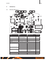
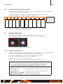
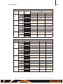
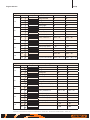
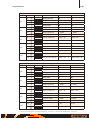
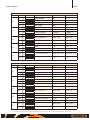
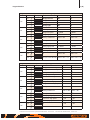
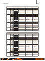
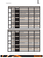
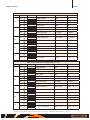
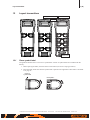
1
INSTALLATION MANUAL
REMOTUS JUPITER
Era 4/6/8B
(RX160, AQ80)
950454-000 EN -B2
Revision history
Version
Date
Reason
A0
2014-05-20
1st released version
B0
2014-09-26
New transmitter configuration menu. New PLC affecting; tandem/multi-operator operation,
two more program selections (EE and FF).
B1
2014-11-13
Tandem operation; pairing transmitter to receiver 2 (B) changed
B2
2014-12-04
Tandem/multi-operator operation, corrected
Reference
RX160 configuration tool, manual 949689-000.

3 (46)
Table of Contents
1Introduction______________________________________________________________ 5
2Scope
__________________________________________________________________ 5
3
Use of warnings and notes in this manual_____________________________________ 6
4
Warnings regarding installation and maintenance work__________________________ 6
5
Specifications____________________________________________________________ 7
5.1Design__________________________________________________________________ 7
5.2
Functional description______________________________________________________ 8
6Installation_______________________________________________________________ 9
6.1
Mechanical installation_____________________________________________________ 9
6.2
Connections and switches on the MAIN board__________________________________ 10
6.3
Cable installation_________________________________________________________ 11
6.3.1
Functional diagram_______________________________________________________________________ 12
6.3.2
Principle connection of the Main contactors____________________________________________________ 12
6.3.3
AC supply_______________________________________________________________________________ 13
6.3.4
DC supply______________________________________________________________________________ 13
6.3.5
Digital inputs____________________________________________________________________________ 13
6.3.6
Analogue input___________________________________________________________________________ 13
6.3.7RS422/485______________________________________________________________________________ 13
6.3.8
6.4
6.4.1
Connection cable_________________________________________________________________________ 13
Antenna placement_______________________________________________________ 14
In case of external antenna placement________________________________________________________ 14
7Commissioning__________________________________________________________ 15
7.1
Frequency setting________________________________________________________ 15
7.1.1
7.2
Radio frequency setting in Receiver RX160____________________________________________________ 15
Transmitter configuration mode______________________________________________ 16
7.2.1
Shutdown Time of the Transmitter____________________________________________________________ 16
7.2.2
PIN-code Configuration of the Transmitter______________________________________________________ 17
7.2.3
Radio Frequency Setting in the Transmitter_____________________________________________________ 18
7.2.4
Adjustment of the Push Buttons Remaining and Momentary Functions_______________________________ 20
7.2.5Radio communication power________________________________________________________________ 20
7.2.6
FX sequence____________________________________________________________________________ 20
7.2.7
Remote type (only Era 8B)__________________________________________________________________ 21
7.2.8
Heavy weight PIN-code____________________________________________________________________ 22
7.2.9
System info_____________________________________________________________________________ 22
7.3
Pair a second ID (for tandem/multi-operator operation)____________________________________________ 23
7.3.2
Pairing indications________________________________________________________________________ 23
7.4
7.5
Micro (slow speed) Operation_______________________________________________ 24
Tandem and Multi-operator Operation________________________________________ 24
7.5.1
Multi-operator operation____________________________________________________________________ 25
7.5.2
Tandem operation ________________________________________________________________________ 25
7.5.3
Tandem operator operation & Multi-operator operation ___________________________________________ 26
7.5.4
Tandem operator operation & Multi-operator operation (Primary/Secondary)___________________________ 27
7.6
7.6.1
8
Pairing of transmitter and receiver___________________________________________ 23
7.3.1
CIM Card_______________________________________________________________ 28
Removing/Mounting CIM Card_______________________________________________________________ 28
Function tests___________________________________________________________ 28
Installation manual Remotus Jupiter Era 4/6/8B FSK12
Version: B2
Document-ID: 950454-000 EN
Author: SH

4 (46)
9Indications______________________________________________________________ 29
9.1Receiver indications______________________________________________________ 29
9.2
Transmitter indications____________________________________________________ 30
9.2.1
Status indicator__________________________________________________________________________ 30
9.2.2
Display indications________________________________________________________________________ 30
10
Trouble shooting_________________________________________________________
10.1 First check______________________________________________________________
10.2 It is impossible to activate the main contactor___________________________________
10.3 Some output functions do not work___________________________________________
31
31
31
32
11
Program Selection_______________________________________________________ 32
11.1 Program Selection list_____________________________________________________ 32
12
Layout transmitters_______________________________________________________ 41
12.1 Place symbol label_______________________________________________________ 41
12.2 Symbol explanation_______________________________________________________ 43
List of figures
Figure 1.
Receiver functional safety description______________________________________________ 8
Figure 2.
Mount RX160_________________________________________________________________ 9
Figure 3.
Connections and switches on the MAIN board_______________________________________ 10
Figure 4.
Installation of cables___________________________________________________________ 11
Figure 5.
Relay symbol explanation_______________________________________________________ 12
Figure 6.
Connection with the two main contactors in parallel, category 3_________________________ 12
Figure 7.
Connection with the two main contactors in series, category 1__________________________ 12
Figure 8.
Internal antenna______________________________________________________________ 14
Figure 9.
Recommended and wrong placement of the antenna_________________________________ 14
Figure 10. Adjust the frequency setting, switch 2_____________________________________________ 15
Figure 11. Micro operation setting, switch 3_________________________________________________ 24
Figure 12. Dipswitch SW3, position in the receiver____________________________________________ 24
Figure 13. Indications on the MAIN board___________________________________________________ 29
Figure 14. LED indicators indicating active outputs____________________________________________ 32
List of tables
Table 1.
Technical specifications_________________________________________________________ 7
Table 2.
Fixed frequency list____________________________________________________________ 19
Table 3.
Receiver pairing indication______________________________________________________ 23
Table 4.
Transmitter pairing indication____________________________________________________ 23
Table 5.
Transmitter display pairing indication______________________________________________ 23
Table 6.
Mode, event and indications on the MAIN board_____________________________________ 29
Table 7.
Symbol placement for Era 4B and 6B_____________________________________________ 42
Table 8.
Symbol placement for the different types of Era 8B___________________________________ 42
Installation manual Remotus Jupiter Era 4/6/8B FSK12
Version: B2
Document-ID: 950454-000 EN
Author: SH
Introduction
1
5 (46)
Introduction
Remotus is Åkerströms product family for radio remote control of safety critical industrial and mobile applications. Remotus Jupiter is Åkerströms’ standardized industrial remote control product line.
The manual must be used when installing Åkerströms Remotus system to ensure a secure and safe operation.
This manual only covers the installation of the Remotus radio remote control system. Remotus does not
include a complete system for remote control: it has only a set of outputs that is controlled by the operator
with the transmitter switches and joysticks. How the outputs are used to control the object (for example, a
machine’s movements and brakes) depend on the specific installation and is outside the scope of the Remotus system.
It is the responsibility of the Systems Integrator or Machine builder to safely incorporate the Remotus radio
remote control into the complete system or machine. The System Integration has to be made by qualified
personnel applying the appropriate standards for the system or machine including making the necessary
safety investigations and risk analysis.
It should be noted that the information obtained from the controlled object is not processed by the Remotus
receiver, but is used for informational purposes.
For the reasons stated above, the safety of Remotus covers mainly the status of the relay outputs, regardless
of the object that is controlled by the relays.
The interface between Remotus and the controlled object should be a special interface that is not included
in Remotus system and therefore is not included in this installation manual.
The approvals for Remotus refer only to the Remotus system not the complete system.
The complete radio control system must be tested and approved in accordance with applicable standards. It
is not part of Åkerströms Björbos responsibility.
2
Scope
The Remotus Jupiter system described in this manual consists of one receiver and one transmitter.
Type
Model
Receiver
RX160
J-RX160
Button transmitter
AQ80
Jupiter Era 4B
Jupiter Era 6B
Jupiter Era 8B
Installation manual Remotus Jupiter Era 4/6/8B FSK12
Symbols
Version: B2
Nordic, DIN, CS or
numbers
Document-ID: 950454-000 EN
Author: SH
Use of warnings and notes in this manual
3
6 (46)
Use of warnings and notes in this manual
Read all safety instructions throughout this manual and on safety signs attached to this equipment.
Failure to follow all safety instructions could result in death or serious injury.
The safety alert symbol is used to alert about potential personal injury hazards. To avoid hazards, obey all
safety messages that follow this symbol. Inform all personnel that are working with the product.
The following safety alert symbols and signal words are used in this manual to inform the user of hazards.
Indicates a potentially risk of high voltage which, if not avoided,
could result in death or serious injury or property damage.
Indicates a potentially hazardous situation which, if not avoided,
could result in death or serious injury or property damage.
!!
Indicates a condition which, if not avoided, could result in damage
to or poor functionality of the product.
Electrostatic sensitive devices warning tells you about the risk of
electrostatic discharge which can cause damage to the product.
4
Warnings regarding installation and maintenance work
This manual must be read and understood before installing and starting the radio remote
control system to ensure safe and secure operation.
The installation and/or maintenance work must be carried out by a qualified and educated
person in accordance with country installation rules and regulations. Only a correct installation can ensure the necessary level of safety during use.
The equipment can be supplied by different energy sources e.g. for the relay contacts or the regular
power supply of the equipment!
Before starting ANY maintenance work ensure by using the external separators / fuses of the
permanent installation, that ALL terminal blocks are free from dangerous voltage!
CAUTION DOUBLE POLE/NEUTRAL FUSING
Risk of high noise level, hearing protection required
If a siren is mounted on the receiver unplug it before any maintenance action.
Put it back when the maintenance is done.
Installation manual Remotus Jupiter Era 4/6/8B FSK12
Version: B2
Document-ID: 950454-000 EN
Author: SH
Specifications
5
7 (46)
Specifications
General:
Operating frequency:
863-870 MHz
915-928 MHz
433-434 MHz
Power output:
< 5 mW
< 3 mW AUS/NZ
< 10 mW
Baud rate:
9600b/s
9600 b/s
9600 b/s
Transmission principle:
GFSK, TDMA
GFSK, TDMA
GFSK, TDMA
Channel Separation:
25 kHz
25 kHz
Functional sensitivity:
≤-107 dBm BER 10
The radio full-fills:
R&TTE Directive 99/5EC
Reaction time on STOP function:
Maximum 550 ms
Safety category for the Stop function
ISO 13849-1 Category 3 PL d
Safety category for unintended movement (UMFS)
ISO 13849-1 Category 3 PL d, possible to achieve with Era 8B.
-3
≤-107 dBm BER 10
25 kHz
-3
≤-107 dBm BER 10-3
Receiver RX160:
16 Relay outputs:
•
6 safety relays (NO) for movements
•
4 change-over relays (NO/NC)
•
6 normally open relays (NO)
2 Separate main contactor change over safety relays
1 Digital output for horn (siren)
12V
1 Analogue input:
0 (4) -20 mA or 0(2)-10 V
2 Digital inputs:
24/48 V AC/DC (Opto-isolated) or 115/230 V AC (Opto-isolated)
1 Serial port:
RS422/RS485
Input voltage:
24/48/115/230 V AC, power consumption less than 14 VA
or 24 V DC 0.5 A. Shall be connected to SELV circuits.
Dimensions:
277x217x115 mm
Weight:
Approximately 1.6 kg
Operating temperature:
Storage temperature:
-25 °C – +55 °C
-40 °C – +85 °C
Transmitter AQ80:
Dimensions:
Weight:
Operating Temperature for battery:
Storage Temperature for battery:
Charging Temperature for battery:
External power supply voltage:
Display:
Table 1.
5.1
181 x 65 x 43 mm
265 g
-20 °C – +55 °C
-20 °C – +35 °C
+10 °C – +45 °C
NOTE! For charging see charger documentation
5 ± 0.25V 100mA max.
Must be supplied with Limited Power Source (LPS)
Graphic LCD, 128x64 pixels
Technical specifications
Design
The RX160 receiver consists of a MAIN board, antenna board and a radio module. The radio module is
located on top of the MAIN board.
The MAIN board holds all logic components, relays, power supply and the connectors.
The enclosure is made of fire resistant UL 94-5V plastic.
Installation manual Remotus Jupiter Era 4/6/8B FSK12
Version: B2
Document-ID: 950454-000 EN
Author: SH
Specifications
5.2
8 (46)
Functional description
The Remotus Jupiter Era system uses a dual channel architecture in both the receiver and the
transmitter to achieve high degree of safety. For additional safety the receiver RX160 is equipped
with eight (8) safety relays whereof two safety relays are intended for safety stop. The other 6
safety relays are used for crane movement and provides protection against unintended movement
due to welded relay contacts (UMFS Category 3 PL d ISO 13849-1:2006).
The dual channel architecture and extensive use of safety relays in the receiver will significantly
increase the safety of the crane system providing that the installation is carried out correctly. To
achieve category 3 Pl d for the STOP function according to ISO 13849-1:2006 both safety stop
outputs from the receiver shall be connected to two independent stop inputs on the crane (two
safety stop channels).
RADIO
Channel A (CPU-A)
Supervising
signals
Main contactor
Safety relays
+5V
+5V
Channel B (CPU-B)
Power supply and voltage monitoring circuits
Figure 1.
feeding
power
Receiver functional safety description
Installation manual Remotus Jupiter Era 4/6/8B FSK12
Version: B2
Document-ID: 950454-000 EN
Author: SH
Installation
6
9 (46)
Installation
The permanent installation of the receiver must include fuses to protect the equipment and wiring from over
current and short circuit. In detail the power supply of the receiver and all relay contacts must be fused.
All fuses are used as disconnecting devices. The fuses shall be easily accessible, must submit a contact-gap
of at least 3.0 mm and have to be placed in the line pole (L). NOTE! The neutral line fuse on the PCBA
is NOT sufficient as a disconnecting device. After removal of the fuse, parts of the equipment will remain
energized and might represent a hazard during servicing.
6.1
Mechanical installation
Note! Make sure to install any optional accessories inside and/or on the receiver enclosure before mounting the receiver on the crane. Refer to each accessory kit for assembly instructions.
196 mm
Mount the receiver upright with the cable
glands facing down. The receiver shall be
mounted on a flat surface with screws suitable for the surrounding environment.
Note! If the plastic spacer is mounted the
screws needs to be 20 mm longer.
Ø 6mm
Assembly Instruction - plastic spacer
229 mm
(optional)
Press the plastic spacers firmly to the bottom
enclosure. Make sure to align the spacers
frame opening with the condensation filter
ventilation on the bottom enclosure lower,
right side.
4 black plastic spacer art. no: 947504-000.
Cable diameter
10-16 mm
Figure 2.
Cable diameter
3-6.5 mm
Mount RX160
When drilling the hole for the cable gland, make sure
not to damage the printed circuit board or the transformer inside. Place some protection inside the enclosure to stop the drill from damaging the interior.
Installation manual Remotus Jupiter Era 4/6/8B FSK12
Version: B2
Document-ID: 950454-000 EN
Author: SH
Installation
6.2
10 (46)
Connections and switches on the MAIN board
Rotary switch
SW1
Rotary switch
SW2
Dipswitch
SW3
Pairing
Horn (siren)
RS422/485
DC supply
24 V DC
Connection for
radio module
Analogue in
Support for cabling
Support for cabling
MC2
MC1
AC supply
Digital input 0
Figure 3.
Digital input 1
Connections and switches on the MAIN board
Installation manual Remotus Jupiter Era 4/6/8B FSK12
Version: B2
Document-ID: 950454-000 EN
Author: SH
Installation
6.3
11 (46)
Cable installation
If the receiver and/or receiver terminals are connected to more than one line phase the
voltage between any connector must NOT exceed 250 V.
If voltage of one phase is 230 V AC the corresponding three phase voltage is 380 V AC
and thus NOT allowed.
Max loading by relay may not be over 2 A.
Current loops containing relay contacts SHALL therefore have a protection fuse not
higher rated than 6 A.
A protection fuse for the receiver main supply shall be rated 6 A.
Do not mix SELV and NON SELV signals in the same cable.
After the installation of the equipment, the installed cables must be bound together in
pairs (e.g. by using a cable tie) very close to the terminal blocks (see Figure 4). This is
important if a cable become loose. The cable should not be able to end up in an unsuitable
location of the receiver.
Fasten with a torque of 0.4-0.5 Nm.
Cabling
Figure 4. Installation of cables
1
3
2
Cable ties
Note! The position of different cable glands can vary depending on combination of accessories.
1 Relay/digital in and hole mounted siren cabling. Note! Relay cabling, use cable ties not only as in Figure 4 but also to hold
them together in the middle. Hole mounted siren cabling to the left.
2 DC supply cabling. Note! The connection from this supply shall be routed through its own cable gland.
3 External siren
RS 422/485 and Analogue in. M12 cable gland at suitable placement. Note! Cabling shall be routed to the left or right.
Pigtail for external antenna. BNC chassis connector in the rightmost hole. Note! Cabling shall be routed as shown in 2 / 3
For relay terminal and connector number see Figure 3 on page 10.
Installation manual Remotus Jupiter Era 4/6/8B FSK12
Version: B2
Document-ID: 950454-000 EN
Author: SH
Installation
12 (46)
NO
NO
NC
Common
Common
Figure 5.
6.3.1
Relay symbol explanation
Functional diagram
The receiver functional diagram shows how to connect the equipment, in this manual the functional diagram is written as different program options, see chapter 11.
6.3.2
Principle connection of the Main contactors
The radio remote control system is, for the safety stop function, designed for category 3 Pl d according to
ISO 13849-1:2006. To achieve this safety level for the object (crane) both safety stop outputs MC1 and
MC2 shall be used as two separate independent outputs (two safety channels). This means that there must
be two main contactors on the machine. See the connection example below.
Line
Neutral
External
fuse 6A
Main contactor control
from receiver
Main contactors
MC1
MC2
Figure 6.
Connection with the two main contactors in parallel, category 3
If category 3 is not desired, the two safety stop outputs MC1 and MC2 shall be used connected in series.
See the connection example below. The maximum level of safety for the safety stop function in this case
will be category 1.
Line
Neutral
External
fuse 6A
Main contactor control
from receiver
MC1
Figure 7.
Main contactor
MC2
Connection with the two main contactors in series, category 1
Installation manual Remotus Jupiter Era 4/6/8B FSK12
Version: B2
Document-ID: 950454-000 EN
Author: SH
Installation
6.3.3
13 (46)
AC supply
230
115
48
24
N
Carefully check the power supply voltage level.
6.3.4
DC supply
The connection cable for the DC supply shall be routed through
its own cable gland.
Do not mix with NON SELV signals.
6.3.5
24VDC
0
Digital inputs
Dig in 0
6.3.6
Analogue input
Do not mix with NON SELV signals.
RS422/485
This signal may be used for weight information from a scale,
shown on the transmitter’s display. See section 9.2.2.
Do not mix with NON SELV signals.
6.3.8
Connection cable
The cable cross-sectional area shall be at least 0.75 mm²
and with an outer insulation diameter of 10-16 mm.
Installation manual Remotus Jupiter Era 4/6/8B FSK12
Version: B2
Document-ID: 950454-000 EN
115/230V
Dig in 1
This signal may be used for weight information from a scale,
shown on the transmitter’s display. See section 9.2.2.
6.3.7
24/48V
Common
115/230V
24/48V
Common
Carefully check the signal voltage level.
These two signals appear as symbols on the transmitter display.
Author: SH
Installation
6.4
14 (46)
Antenna placement
The antenna is by default placed internally in Jupiter RX160.
Antenna board
Antenna connector
Figure 8.
6.4.1
Internal antenna
In case of external antenna placement
When mounting the antenna separately it must be placed as open (in free air) as possible preferably below
the crane beam.
A covered antenna contributes to a considerably less effective radio reception. An antenna can not be
mounted in a cabinet.
Crane/Hoist
Crane
beam
50 ohm
Antenna cable
45˚
Antenna
Wrong placement
45˚
Recommended placement
Figure 9.
Recommended and wrong placement of the antenna
!! The antenna must never come into contact with metal parts.
If the antenna is installed outdoors, there is a risk of dangerous voltages entering the antenna cable.
To minimize this risk a DC block shall be used. DC blocks are coaxial components that prevent the
flow of low and direct current (DC) frequencies while offering minimum interference to RF signals.
Suitable models have capacitors in series with both the inner and outer conductors.
Åkerströms can provide one suitable DC block 944498-000.
Installation manual Remotus Jupiter Era 4/6/8B FSK12
Version: B2
Document-ID: 950454-000 EN
Author: SH
Commissioning
15 (46)
7
Commissioning
7.1
Frequency setting
The radio transmission used in the Jupiter systems can use either a frequency hopping transmission scheme
or scan mode were frequency are automatically selected. The default factory setting is frequency hopping
which is recommended for most applications.
Note! The transmitter and receiver must have the same frequency setting.
Frequency hopping
Frequency band 800 uses LBT+AFA frequency hopping transmission.
Frequency band 900 and 400 uses frequency hopping transmission.
AFA - Adaptive Frequency Agility capability of an equipment to dynamically change the temporary
operational channel within its available frequencies for proper operation.
LBT - Listen Before Talk
capability of an equipment to disable transmission on a specific radio
channel if the channel is busy.
When frequency hopping is selected, the frequency changes automatically between 15 different
frequencies in the frequency-band.
Scan mode
Scan free frequency
Scan free frequency scheme automatically scans between 15 different frequencies and one
frequency in the frequency-band will be used. The transmitter changes to a free frequency every
time it´s started, as long as the transmitter searches for a free frequency the status indicator
glows yellow.
Fixed frequency
Fixed frequency channel set by the user. For Receiver setting refer to RX160 configuration tool
and for transmitter, see chapter 7.2.3.
7.1.1
Radio frequency setting in Receiver RX160
Before changes of the frequency setting, disconnect the power.
The SW3 dipswitch for adjusting frequency setting
is marked in Figure 3. See Figure 10 for settings.
Frequency hopping
ON
Scan mode
ON
If switch 2 is set to:
1
2
3
4
OFF: Frequency hopping
1
2
3
Figure
10.
Adjust
the
frequency
ON: Scan mode, automatically selected frequency also fixed frequency
4
setting, switch 2
The receiver RX160 normally uses frequency hopping for radio communication. By watching the indications “Squelch” (LED 4) and “Message received” (LED 3) it is possible to diagnose the quality of the
radio channel (see section 9.1 on page 29).
• E
very time a message is received the indication “Squelch” lit. The messages are sent at a constant
rate. The indication “Squelch” shall lit at this rate. If this isn’t the case some of the channels can be
occupied or some of the used frequencies (1 of 15) are not working.
• If the message is accepted by the receiver, indication “Message received” will lit.
If the indication “Message received” does not lit at the same rate as the indication “Squelch” the messages
on one or more frequencies are disturbed or distorted.
Note! The transmitter has to be set to the same frequency setting, see section 7.2.3 on page 18.
Installation manual Remotus Jupiter Era 4/6/8B FSK12
Version: B2
Document-ID: 950454-000 EN
Author: SH
Commissioning
7.2
16 (46)
Transmitter configuration mode
Enter configuration menu
Press button B8 (2nd step) while pulling up the safety
stop button. Hold down the button 3 seconds until
the status indicator glows yellow showing that the
transmitter is in configuration mode.
Config menu
xxx
Submenu
Browse submenu with the buttons B1 and B2.
Choose submenu with button B8. To return to the
main menu while you are in a submenu, press button
B7.
Browse
Browse
Submenus:
• “Shutdown”
Choose
/OK
• “PIN-code”
• “Frequency”
• “433 MHz”
• “Button function”
Enter config menu
Configuration menu
• “Radio comm power”
• “FX sequence”
• “Remote type”
• “Heavy weight PIN-code”
• “System info”
Exit/Save
Finish by turning the transmitter off by pushing the
safety stop button down. This also saves the changes
that have been made.
7.2.1
Shutdown Time of the Transmitter
The transmitter shuts down automatically if not used for a certain
amount of time. This time can be adjusted in the transmitter configuration menu.
Shutdown
xxx
1. Enter the configuration menu.
2. Then select “Shutdown” with B8 (browse with B1 and B2).
3. Then browse the desired shutdown time with B1 and B2:
• “2 minutes”
Browse
Browse
Back
Choose
/OK
• “5 minutes”
• “15 minutes”
• “no shutdown”
Already selected shutdown time is indicated by button LED B1.
4. Select shutdown time by press down button B8.
5. Automatic return to the main menu or restart the transmitter.
Shutdown time
Installation manual Remotus Jupiter Era 4/6/8B FSK12
Version: B2
Document-ID: 950454-000 EN
Author: SH
Commissioning
7.2.2
17 (46)
PIN-code Configuration of the Transmitter
The transmitter is equipped with a user configurable PIN-lock to prevent unauthorized access to the system.
The PIN-lock is disabled by default.
1. Enter the configuration menu.
2. Then select “PIN-code” with B8 (browse with B1 and B2).
3. Enter PIN:
For enable enter the factory setting 3333 and
for disable enter the old PIN-code.
Press B1 repeatedly to select number and B8 to choose the number. Delete a number with B2.
4. Enter new PIN:
Enter the new 4-digit PIN.
For enable enter the new PIN (not 3333) and
for disable enter the factory setting 3333.
Select
number
(Press B1
repeatedly)
5. Repeat PIN:
Repeat the PIN code.
Delete
number
Choose
number
6. Automatic return to the main menu or restart the transmitter.
PIN code Enable/Disable
7.2.2.1 Entering PIN-code at start-up
When PIN is enabled the transmitter will not start to transmit before the correct PIN-code is entered. If
the transmitter is PIN locked at startup status indicator shows red continuous light. Display will show
“Enter PIN”.
Enter the 4-digit PIN-code by press B1 repeatedly to select number and B8 to choose the number. Delete
a number with B2. When all 4-digit are selected, press B8 once again to select the PIN code.
At successful login the status indicator shows green flashing. Display shows “PIN OK!”. The unit is now in
operating mode.
Installation manual Remotus Jupiter Era 4/6/8B FSK12
Version: B2
Document-ID: 950454-000 EN
Author: SH
Commissioning
7.2.3
18 (46)
Radio Frequency Setting in the Transmitter
To change the settings do the following:
1. Enter the configuration menu.
Frequency
xxx
2. Then select “Frequency” with B8 (browse with B1 and B2).
3. Then browse to the desired setting with B1 and B2.
• “Frequency hopping”
• “Scan mode”
Browse
Browse
Back
Choose
/OK
• “Channel 0-XX”
Already selected setting is shown when entering the frequency setting menu.
4. Select setting by press down button B8.
5. Automatic return to the main menu or restart the transmitter.
• Frequency hopping: When frequency hopping is selected, the frequency changes automatically
between different frequencies in the frequency-band.
• Scan Mode: Automatically scans between different frequencies and one frequency in the frequencyband will be used. The transmitter changes to a free frequency every time it´s started, the scan will start at
the same frequency that was used last time the transmitter was started.
• Channel: Sets a specific channel.
See “7.2.3.2 Fixed frequency” on page 19.
7.2.3.1 433 MHz (only frequency band 400)
In frequency band 400 there is an opportunity to select region.
1. Enter the configuration menu.
2. Then select “433 MHz” with B8 (browse with B1 and B2).
3. Then browse to the desired setting with B1 and B2.
• “EU”
• “Other”
Browse
Browse
Back
Choose
/OK
Already selected setting is indicated by button LED B1.
4. Select setting by press down button B8.
5. Automatic return to the main menu or restart the transmitter.
!!
Note. If the equipment is being operated in EU-region this
setting has to be set to EU for correct fulfill the regulation!
See “Appendix 1 - European Radio Regulation” on page 45.
Other make sure to fulfill any rules or regulations or
!! For
any applicable local, state, or federal governing laws.
Installation manual Remotus Jupiter Era 4/6/8B FSK12
Version: B2
Document-ID: 950454-000 EN
Author: SH
Commissioning
19 (46)
7.2.3.2 Fixed frequency
Channel no
0
1
2
3
4
5
6
7
8
9
10
11
12
13
14
15
16
17
18
19
20
21
22
23
24
25
26
27
28
29
30
31
32
33
34
35
36
37
38
39
40
41
42
43
44
45
46
47
48
49
50
51
52
53
54
55
56
57
58
59
869MHz
869,7125
869,7375
869,7625
869,7875
869,8125
869,8375
869,8625
869,8875
869,9125
869,9375
869,9625
869,9875
434MHz EU
434,05
434,075
434,1
434,125
434,15
434,175
434,2
434,225
434,25
434,275
434,3
434,325
434,35
434,375
434,4
434,425
434,45
434,475
434,5
434,525
434,55
434,575
434,6
434,625
434,65
434,675
434,7
434,725
434,75
434,775
433-434MHz Extended
433,3
433,325
433,35
433,375
433,4
433,425
433,45
433,475
433,5
433,525
433,55
433,575
433,6
433,625
433,65
433,675
433,7
433,725
433,75
433,775
433,8
433,825
433,85
433,875
433,9
433,925
433,95
433,975
434
434,025
434,05
434,075
434,1
434,125
434,15
434,175
434,2
434,225
434,25
434,275
434,3
434,325
434,35
434,375
434,4
434,425
434,45
434,475
Note! Fixed frequency only applied
434,5
on system version 1.20 or later.
434,525
See system version on the display at
434,55
start up of the transmitter.
434,575
434,6
434,625
434,65
434,675
434,7
434,725
434,75
434,775
Table 2.
Fixed frequency list
Installation manual Remotus Jupiter Era 4/6/8B FSK12
Version: B2
Document-ID: 950454-000 EN
Author: SH
Commissioning
7.2.4
20 (46)
Adjustment of the Push Buttons Remaining and Momentary Functions
The buttons either have momentary functions, which give a signal for only as long as you keep pressing,
or remaining functions.
Note that this function needs support from the receiver PLC. Before changing these parameters,
check the program options. Only qualified personnel may make these changes.
1. Enter the configuration menu.
2. Then select “Button function” with B8 (browse with B1 and B2).
3. Press down the buttons for which you want to have a remaining/momentary function. Lighted button LED indicates remaining function. Note: The three pair of buttons 1-2, 3-4 and 5-6 must have
the same settings within the pair. Otherwise the momentary function is disabled on the button that
is not remaining.
4. Restart the transmitter.
7.2.5
Radio communication power
To change the settings do the following:
1. Enter the configuration menu.
Radio Com
xxx
2. Then select “Radio comm power” with B8
(browse with B1 and B2).
3. Then browse to the desired setting with B1 and B2.
• “Auto power”
Browse
Browse
Back
Choose
/OK
• “100 % power”
• “25 % power”
Already selected setting is indicated by button LED B1.
4. Select setting by press down button B8.
5. Automatic return to the main menu or restart the transmitter.
7.2.6
FX sequence
To change the settings do the following:
1. Enter the configuration menu.
FX sequence
xxx
2. Then select “FX sequence” with B8
(browse with B1 and B2).
3. Then browse to the desired setting with B1 and B2.
• “255 X:XX Disabled”
Browse
Browse
Back
Choose
/OK
• “000 0:0 - 119 7:14”
Already selected setting is the first one that comes up when
entering the menu.
4. Select setting by press down button B8.
5. Automatic return to the main menu or restart the transmitter.
Installation manual Remotus Jupiter Era 4/6/8B FSK12
Version: B2
Document-ID: 950454-000 EN
Author: SH
Commissioning
7.2.7
21 (46)
Remote type (only Era 8B)
The Jupiter Era 8B transmitter can be set to 8/9 or 10 Buttons. For 9 and
10 more functions can be admitted with a SHIFT-function (B8 2nd step).
The functionality of the transmitter is depending
!! NOTE!
on this setting. This setting also alters the placement and
Remote
xxx
symbols on the transmitter, see section 12.1.
8 Buttons
Era 8B standard
9 Buttons
Standard + selection of 1&2 and A&B functions
10 Buttons
Standard + selection of 1&2 functions
Browse
Browse
Back
Choose
/OK
To change the settings do the following:
1. Enter the configuration menu.
2. Then select “Remote type” with B8 (browse with B1 and B2).
3. Enter PIN-code (see to box to the right).
Press B1 repeatedly to select number and B8 to choose the number.
Delete a number with B2.
4. Then browse to the desired setting with B1 and B2.
• “8 BUTTONS”
• “9 BUTTONS”
• “10 BUTTONS”
PIN-code:
Go to system info (see 7.2.9).
ID=XXXXX:YY Z/Z take the
first five numbers (X). This
is the PIN-code. If there only
are four numbers enter a 0
before them 0XXXX.
Already selected setting is indicated by button LED B1.
5. Select setting by press down button B8.
6. Automatic return to the main menu or restart the transmitter.
Installation manual Remotus Jupiter Era 4/6/8B FSK12
Version: B2
Document-ID: 950454-000 EN
Author: SH
Commissioning
7.2.8
22 (46)
Heavy weight PIN-code
The transmitter is equipped with a user configurable heavy weight PIN-lock to prevent unauthorized access
to heavy weight lift. The heavy weight PIN-code is disabled by default.
Enable Heavy weight PIN code:
1. Enter the configuration menu.
2. Then select “Heavy weight PIN code” with B8
(browse with B1 and B2).
3. Enter PIN:
Enter the four last numbers of the CIM ID.
4. Enter new PIN:
Enter the new 4-digit PIN (not same as the four last in CIM
ID).
Select
number
(Press B1
repeatedly)
Delete
number
5. Repeat PIN:
Repeat the PIN-code.
6. Automatic return to the main menu or restart the transmitter.
Choose
number
Back
Disable Heavy weight PIN code:
1. Enter the configuration menu.
PIN code Enable/Disable
2. Then select “Heavy weight PIN code” with B8
(browse with B1 and B2).
3. Enter PIN:
Enter the old PIN-code.
PIN-code (CIM ID):
Go to system info (see 7.2.9).
ID=XXXXX:YY Z/Z take the
four last numbers (X). This is
the PIN-code.
4. Enter new PIN:
Enter the four last number of the CIM ID.
5. Repeat PIN:
Repeat the PIN-code (four last number of the CIM ID).
6. Automatic return to the main menu or restart the transmitter.
Note! Heavy weight PIN-code only
applied on system version 1.20 or
later. See system version on the
display at start up of the transmitter.
7.2.8.1 Enter and activate heavy weight PIN during operation
When heavy weight PIN is enabled the system will not lift heavy weight (over 5-ton) before the correct
heavy weight PIN code is entered.
1. Press and hold down the button B7 (step 2) for more than 3 seconds. This will activate the heavy
weight PIN-code entry mode.
2. Enter the 4-digit heavy weight PIN-code by press B1 repeatedly to select number and B8 to choose
the number. Delete a number with B2.
3. After the four digits have been entered the transmitter returns to normal operation mode. If the correct 4-digit PIN code is entered, button LED 7 will light and the remaining function for button B7
will continue to be active (heavy weight activated).
7.2.8.2 Deactivate heavy weight during operation
Press and hold down the button B7 (step 2) for more than 3 seconds until button LED B7 goes out.
7.2.9
System info
Shows firmware version for the CIM card, ID number and package rate.
Press any of the two bottom buttons for exit this menu.
Installation manual Remotus Jupiter Era 4/6/8B FSK12
Version: B2
Document-ID: 950454-000 EN
Author: SH
Commissioning
7.3
23 (46)
Pairing of transmitter and receiver
Open the lid on the receiver. Indications LED 5&6 (see Figure 13) and the pairing push
button (see Figure 3) on the MAIN board should be used when pairing the receiver and
transmitter.
1. Press the pairing button in the receiver.
2. Set the transmitter in pairing mode.
Hold down button B7 and B8 when starting the transmitter. Continue to press the
buttons for ≈5 seconds.
3. See pairing indications, next section. When paired LED 5 shows steady green. If this
hasn’t been indicated within 15 seconds restart the transmitter.
4. Restart the system to activate the new ID number.
The receiver has now learned the transmitter ID number and will only accept commands
from that transmitter.
Enter pair mode
7.3.1
Pair a second ID (for tandem/multi-operator operation)
See section “7.5 Tandem and Multi-operator Operation” on page 24.
7.3.2
Pairing indications
Mode
Event
LED indication Receiver
Flash rate
Pairing
In pairing mode
LED 6 fast
LED 5 steady
50/50 ms
Paired
LED 5 steady
Table 3.
Event
Not paired
Paired
Status indicator transmitter
Green/yellow
Steady green
Flash rate
50/50 ms
Transmitter pairing indication
Pairing:
Pairing ready:
Link timeout:
Pair mode
Pair mode
Pair mode
Pairing...
Paired!
Failed!
↓
Table 5.
LED 6 LED 5
Receiver pairing indication
Mode
In pairing mode
Table 4.
Pairing button
↓
Restart
Restart
System!
Pair mode!
Transmitter display pairing indication
Installation manual Remotus Jupiter Era 4/6/8B FSK12
Version: B2
Document-ID: 950454-000 EN
Author: SH
Commissioning
7.4
24 (46)
Micro (slow speed) Operation
The SW3 dipswitch for adjusting micro setting is marked in Figure 3. See Figure 11 for settings.
Non simultaneous - SW3:3 OFF
ON
The buttons/joysticks for movement are
interlocked during this time so that only
one movement can be operated at a time.
1
2
3
4
Non simultaneous
2
3
4
Simultaneous
ON
Simultaneous - SW3:3 ON
The buttons/joysticks for movements are
looped so that two or more movements
can be operated simultaneously.
1
Figure 11. Micro operation setting, switch 3
!! Note! Micro operation is not possible with Era 8B “9 Buttons”.
For Era 8B “10 Buttons” B8 1 step (micro) needs to be pressed down 0.3 seconds
!! Note!
for activation of micro function.
st
7.5
Tandem and Multi-operator Operation
!! Only transmitter 8B set to 9 or 10 Buttons (see section 7.2.7).
is strongly recommended to use scan free frequency setting for any of the tandem/multi operator
!! Itmodes.
This will significantly increase the speed of the radio synchronization during crane selection.
Tandem Operation
Tandem operation means that two cranes can be operated from the same transmitter, which makes
it easier, for example to lift two objects simultaneously or a big object using two cranes.
A data link is needed between the two cranes. This link shall fulfil at least EN ISO 13849-1:2008
Performance Level c and category 2.
Multi-operator Operation
Multi-operator operation means that two transmitters can operate the same object. This can be
beneficial, for example, when the view is blocked. The control of the object can be passed
between two transmitters. Active crane selection and deselection guarantees that only one transmitter is in control of the object at a time.
Pairing
Dipswitch
SW3
Figure 12. Dipswitch SW3, position in the receiver
Follow the pairing instruction described in section 7.3, but notice the difference of SW3 when pairing the
different transmitters and receivers. For settings of dipswitch SW3 see respective section.
Installation manual Remotus Jupiter Era 4/6/8B FSK12
Version: B2
Document-ID: 950454-000 EN
Author: SH
Commissioning
7.5.1
25 (46)
Multi-operator operation
2 transmitters and 1 receiver
In order to run multi-operator operation the receiver must be paired with two ID’s. First paired transmitter = transmitter 1.
1. Pair transmitter 1 to the receiver. Disconnect and reconnect the power source to the receiver.
2. Pair transmitter 2 to the receiver. Disconnect the power source to the receiver, set the SW3 in “during operation” and reconnect the power source to the receiver
During pairing
A
Transmitter 1
Receiver A
1
2
3
4
SW3:1 OFF, SW3:3 OFF
Transmitter 2
7.5.2
ON
1
A
1 2
During operation
2
ON
1
ON
1
2
3
4
SW3:1 ON, SW3:3 OFF
2
3
4
SW3:1 ON, SW3:3 OFF
Tandem operation
1 transmitter and 2 receivers
In order to run tandem operation the receivers must be paired with the same ID.
1. Pair the transmitter to receiver 1 (A). Disconnect the power source to the receiver, set the SW3 in “during
operation” and reconnect the power source to the receiver.
2. Pair the transmitter to receiver 2 (B). Disconnect the power source to the receiver, set the SW3 in “during
operation” and reconnect the power source to the receiver.
During pairing
A
B
Receiver A
A
Transmitter 1
1
Receiver B
B
1
Installation manual Remotus Jupiter Era 4/6/8B FSK12
1
Version: B2
ON
2
3
4
SW3:1 OFF, SW3:3 OFF
Transmitter 1
1
ON
ON
1
During operation
1
2
3
4
SW3:1 ON, SW3:3 OFF
ON
2
3
4
SW3:1 ON, SW3:3 OFF
Document-ID: 950454-000 EN
1
2
3
4
SW3:1 ON, SW3:3 ON
Author: SH
Commissioning
7.5.3
26 (46)
Tandem operator operation & Multi-operator operation
2 transmitters and 2 receivers
In order to run tandem/multi-operator operation the receivers must be paired with two ID’s.
1. Pair transmitter 1 to receiver 1 (A). Disconnect and reconnect the power source to the receiver.
2. Pair transmitter 2 to receiver 1 (A). Disconnect the power source to the receiver, set the SW3 in “during
operation” and reconnect the power source to the receiver.
3. Pair transmitter 2 to receiver 2 (B). Disconnect and reconnect the power source to the receiver.
4. Pair transmitter 1 to receiver 2 (B). Disconnect the power source to the receiver, set the SW3 in “during
operation” and reconnect the power source to the receiver.
Transmitter 1 primary transmitter for receiver 1 (A). Transmitter 2 primary transmitter for receiver 2 (B).
During pairing
Transmitter 1
ON
1
1
Receiver A
A
B
A
2
3
During operation
4
ON
SW3:1 OFF, SW3:3 OFF
Transmitter 2
ON
2
1
1
2
3
4
SW3:1 ON, SW3:3 OFF
2
3
4
SW3:1 ON, SW3:3 OFF
Transmitter 2
ON
2
1
Receiver B
1
2
B
2
3
4
ON
SW3:1 OFF, SW3:3 OFF
Transmitter 1
1
1
ON
2
Version: B2
4
SW3:1 ON, SW3:3 ON
1
2
3
4
SW3:1 ON, SW3:3 OFF
Installation manual Remotus Jupiter Era 4/6/8B FSK12
3
Document-ID: 950454-000 EN
Author: SH
Commissioning
7.5.4
27 (46)
Tandem operator operation & Multi-operator operation (Primary/Secondary)
2 transmitters and 2 receivers (one of the transmitters can only operate one crane)
In order to run tandem/multi-operator operation the receivers must be paired with two ID’s.
1. Pair transmitter 1 to receiver 1 (A). Disconnect the power source to the receiver, set the SW3 in “during
operation” and reconnect the power source to the receiver.
2. Pair transmitter 2 to receiver 2 (B). Disconnect and reconnect the power source to the receiver.
3. Pair transmitter 1 to receiver 2 (B). Disconnect the power source to the receiver, set the SW3 in “during
operation” and reconnect the power source to the receiver.
Transmitter 1, can operate both cranes, primary transmitter for receiver 1 (A) and secondary for receiver 2 (B).
Transmitter 2, can operate one crane, primary transmitter for receiver 2 (B).
During pairing
Receiver A
A
B
A
Transmitter 1
ON
1
1
During operation
ON
2
3
4
SW3:1 OFF, SW3:3 OFF
Receiver B
B
1
2
Transmitter 2
ON
2
1
2
3
4
1
2
4
SW3:1 ON, SW3:3 OFF
ON
SW3:1 OFF, SW3:3 OFF
Transmitter 1
ON
1
1
1
2
Version: B2
3
4
SW3:1 ON, SW3:3 ON
2
3
4
SW3:1 ON, SW3:3 OFF
Installation manual Remotus Jupiter Era 4/6/8B FSK12
3
Document-ID: 950454-000 EN
Author: SH
Function tests
7.6
28 (46)
CIM Card
The CIM card is used for storing configuration information. You can take out the CIM-module from one
system and place it in a spare transmitter with the same system program and it will work exactly* the same.
This exchange has to be done in a clean, dry and ESD safe environment.
avoid personal and/or damages on property; exchange CIM card ONLY when the
!! To
transmitter battery has been removed.
that some settings do not follow with the CIM card and need to be set in the “spare”
!! *Note
transmitter. These settings are; Radio comm power, FX sequence 0-119 and Remote type.
7.6.1
Removing/Mounting CIM Card
2
1
1. To disassemble the transmitter, remove the battery, unscrew the six screws*
holding the back cover of the transmitter, pull up the back of the transmitter
carefully and pull out the connector for the battery and remove the back enclosure entirely.
*Note that the screw below the battery is underneath the type label. Make a
little cut on the type label around the screw; so not the entire type label is damage when removing the screw.
2. The CIM card 1 is located at the top of the transmitter above the display board
2 . Gently remove the CIM card straight up.
3. Install the CIM card primarily in the original transmitter, alternative spare transmitter. Be sure to insert the CIM card properly in its connector.
4. Reinstall the enclosure. The screws should be tightened with 0.35Nm±0.05.
5. Insert battery. Now, the transmitter is ready for operation.
8
Function tests
Before the following test is performed, make sure to prevent unintended movements of the controlled
object from becoming a safety hazard.
Check that the transmitter can control the receiver by testing all functions and note if the output relays and
the corresponding inputs on the controlled object are activated.
Follow the local safety regulations for the equipment and start the equipment as described in the Operator
Manual.
Check the following:
• Are all movements correct?
• Do the other functions operate correctly?
• Does the stop function on the transmitter work properly?
• Also test the stop function by removing the battery in the transmitter.
• Is it possible to control the equipment from the normal controllers? If it is possible to operate the
equipment from more than one controller at a time the system is incorrectly installed.
• There should be a changeover switch between radio/pendant controls to prevent control from two
places at the same time.
• Test that all the safety and stop limits switches work.
This list of test is for reference only and can be extended by the system integrator in the specific installations
and the corresponding risk analysis.
Installation manual Remotus Jupiter Era 4/6/8B FSK12
Version: B2
Document-ID: 950454-000 EN
Author: SH
Indications
29 (46)
9
Indications
9.1
Receiver indications
LED 4
LED 3
LED 2
LED 1
LED 6
LED 5
MC OK
Indicates activated
main contactor
LED28, LED27
Figure 13. Indications on the MAIN board
Mode
Event
Indication on RX
Flash rate
LED 1-4
TX command change
Changes in the transmitter LED 1 flashes
switches or joysticks
Digital input data change
LED 2 flashes
Message received
LED 3
Squelch
Signal strength > -90 dBm
System OK
Not connected
LED 5 fast
50/50 ms
Connected, MC=OFF
LED 5 slow
50/250 ms
Connected, MC=ON
LED 5 extra slow
30/970 ms
50% time out
LED 5 and LED 6 steady
Receiver internal error
LED 6 steady
Transmitter internal error
LED 6 fast
50/50 ms
In pairing mode
LED 5 steady
LED 6 fast
50/50 ms
LED 4
LED 5-6
ERROR
Pairing
ON/OFF
Paired
LED 5 steady
LED 27-28
MC activated
Table 6.
LED 27 & 28 steady
Mode, event and indications on the MAIN board
Installation manual Remotus Jupiter Era 4/6/8B FSK12
Version: B2
Document-ID: 950454-000 EN
Author: SH
Indications
30 (46)
9.2
Transmitter indications
9.2.1
Status indicator
If the transmitter under start up (if not PIN locked) or operation detects a fault in any of the transmitters
self-tests, the status indicator (see section 12) will indicate a continuous red light, after which the transmitter is shut down.
9.2.2
INDICATIONS
EXPLANATIONS
Green flashing
OK, normal operation
Yellow quick flashing
Battery voltage low <3.5 V
Yellow continuous, during operating
Battery empty. Transmitter will shut-off within 10s
Yellow continuous, at start-up
Configuration mode
Red continuous, at start-up
PIN locked
Red continuous, during operation
Hardware fault
Blue continuous, other indications may occur simultaneously
High power
Display indications
These default symbols can appear on the display depending on the configuration. For configuration see RX160 configuration tool manual.
1
6
2
3
4
1. Radio signal / MC
2. SHIFT-selection (Era 8B 9/10 Buttons)
3. Text field (crane id etc.)
4. External power supply
5. Battery level
6. Dig. In 1 & 2 (shows if active)
7. Overload warning
8. Weight load graph (full-scale=max load)
9. Weight, up to 5 digits
10. Weight unit (kg,t or lb)
5
Crane 1
1
2
7
1
2
A
B
14.1kg
8
9
10
9.2.2.1 Radio signal quality
No radio link established
Weak signal
Good signal
Strong signal
Very strong signal
MC on is indicated by a line beneath the radio signal symbol, example
.
9.2.2.2 Text field (crane id etc.) (option)
This text is configured in the receiver (8 characters) using the RX160 configuration tool.
9.2.2.3 Battery level
Battery empty
25%
50%
75%
100% (fully charged)
9.2.2.4 Weight / Graph / Overload (option)
The weight is shown with the unit symbol kg, t or lb. depending on the receiver configuration.
The bar graph displays the weight load. Full scale= maximum load. The graph is only shown if a maximum weight limit is configured in the receiver.
This
symbol appears if the load on the crane reaches the weight limit (overload).
Refer to the RX160 configuration tool.
9.2.2.5 SHIFT-selection (only Era 8B 9/10 BUTTONS)
Shows which selections that currently are active.
Installation manual Remotus Jupiter Era 4/6/8B FSK12
Version: B2
Document-ID: 950454-000 EN
Author: SH
Trouble shooting
10
Trouble shooting
10.1
First check
31 (46)
On push button transmitter:
Ensure that a charged battery is inserted in the transmitter.
The status indicator indicates following:
• Slow green flashing means that the transmitter is fully operational
• Fast yellow flashing means that the battery needs charging
• Steady yellow light means that the transmitter is in configuration mode
• Steady red light at start up means that the transmitter is PIN locked
• Steady red light during operating means that an error in the transmitter
has been discovered and it will shut itself down
In receiver:
• Check the indications of mode “Error”, “MC activated” and “System OK”,
see Table 6 on page 29.
10.2
It is impossible to activate the main contactor
The transmitter has not been paired with the receiver. For LED position see Figure 13.
Indication Squelch (LED 4) is flashing or lit but the transmitter is off.
• This means that some or all frequencies are used. Try an alternative frequency setting.
Indication Message received (LED 3) does not flash and the transmitter is on.
• Check the antenna on the receiver.
• All the settings are correct on both the transmitter and the receiver; the system must be checked by
authorised personnel.
Indication Message received (LED 3) lit and indication LED 5 lit but the main contactor remains deactivated.
• Check the instructions in the operator’s manual dealing with activation of the main contactor. Normally the horn/siren push button must be pressed to activate the main contactor. At start up the push
buttons or joystick must be in not activated position.
• A fault in the receiver prevents the main contactor to be activated.
Installation manual Remotus Jupiter Era 4/6/8B FSK12
Version: B2
Document-ID: 950454-000 EN
Author: SH
Program Selection
10.3
32 (46)
Some output functions do not work
If the LEDs indicate the output function the fault is likely to be found in the relay itself or in the cables/
contacts or in the controlled units’ electronics.
If no LEDs are indicate the output function the fault is likely to be found in the transmitter.
Note LED1 is flashing if a command is changed from the transmitter.
REL10
REL9
REL8
In front of every
relay there is a
LED indicating
an active relay.
LED17
LED18
LED25
LED26
LED16
REL7
REL6
LED15
REL5
LED14
REL4
LED13
REL3
LED12
REL2
LED11
REL1
REL11
LED19
REL12
LED20
Figure 14. LED indicators indicating active outputs
11
Program Selection
There are two rotary switches for program selection in the receiver, see section 11.1,
rotary switch SW1 and SW2. For position on the main board see Figure 3 on page 10.
Note! The switches must be set to the same position.
11.1
Program Selection list
If nothing but the movement itself is described in the function column it means step 1+2 on the button transmitter.
Low speed step 1 and high speed step 2. SHIFT=B8 step 2 for Era 8B 9/10 Buttons.
For symbols on the transmitter see chapter “12 Layout transmitters” on page 41.
For relay see “Figure 5. Relay symbol explanation” on page 12.
Every program option is for 3 movements and 2 steps.
Safety relays (Y0-Y5) for movements is indicated by bold text in the function column.
!! For Australia it is a 5 second delay for the “lamp”
Australia: Program option D = 1 but with the difference that output Y11 is
!! For
activated by Up/Down/North/South/East/West-” movement activated”
!! Difference in program selection at Tandem/Multi-operator operation:
Program option 0:
!! Not available for tandem/multi-operator operation.
Program option 1-D:
Y14 indication driver A and Y15 indication driver B
Program option 1,2,4,6,A,B,D: Y13 interconnection crane A & B
Program option 3,5,7,8,9,C:
Y9 interconnection crane A & B
Installation manual Remotus Jupiter Era 4/6/8B FSK12
Version: B2
Document-ID: 950454-000 EN
Author: SH
REL13
LED21
REL14
LED22
Program Selection
33 (46)
Program Option 0 - 8pcs Single functions for JUPITER Era 4/6/8B
Terminal
P21
Connector
Function
Cable part
8B
6B
4B
Y4
B1
B1
B1
Y5
B2
B2
B2
Y6
B3
B3
-
Y7
B4
B4
-
Y8
B5
-
-
Y9
B6
-
-
Y10
-
-
-
Y11
-
-
-
Y12
B7
B7
B7
Y13
B8
B8
B8
Y14
-
-
-
Y15
-
-
-
P27
P20
P18
Program Option 1 - 3 outputs per movement
Terminal
P15
P21
Connector Cable part
Function
Button no.
Button no. DIN
Y0
Bridge forward
B5
B6
Y1
Bridge backward
B6
B5
Y2
Trolley left
B3
B3
Y3
Trolley right
B4
B4
Y4
Hoist down
B2
B1
Y5
Hoist up
B1
B2
Y6
Bridge high speed
2 B5/B6
2nd B6/B5
Y7
Trolley high speed
2nd B3/B4
2nd B3/B4
Y8
Trolley 1/Selection 1
B5 + SHIFT
B5 + SHIFT
Y9
Trolley 2/Selection 2
B6 + SHIFT
B6 + SHIFT
Y10
Hoist high speed
2nd B2/B1
2nd B1/B2
Y11
X
2nd B7
2nd B7
Y12
Y
2nd B8
2nd B8
Y13
A
SHIFT + B3
SHIFT + B3
Y14
B
SHIFT + B4
SHIFT + B4
Y15
Horn (Signal)
1st B7
1st B7
nd
P27
P20
P18
Installation manual Remotus Jupiter Era 4/6/8B FSK12
Version: B2
Document-ID: 950454-000 EN
Author: SH
Program Selection
34 (46)
Program Option 2 - Different outputs for high speed up and down
Terminal
P15
P21
Connector
Cable part
Function
Button no.
Button no. DIN
Y0
Bridge forward
B5
B6
Y1
Bridge backward
B6
B5
Y2
Trolley left
B3
B3
Y3
Trolley right
B4
B4
Y4
Hoist down
B2
B1
Y5
Hoist up
B1
B2
Y6
Bridge high speed
2nd B5/B6
2nd B6/B5
Y7
Trolley high speed
2nd B3/B4
2nd B3/B4
Y8
Trolley 1/Selection 1
SHIFT + B5
SHIFT + B5
Y9
Trolley 2/Selection 2
SHIFT + B6
SHIFT + B6
Y10
Hoist down high speed 2nd B2
2nd B1
Y11
Hoist up high speed
2nd B1
2nd B2
Y12
X
2nd B7
2nd B7
Y13
Y
2nd B8
2nd B8
Y14
A
SHIFT +B3
SHIFT + B3
Y15
B / (Horn button 8B/10B)
SHIFT + B4 / 1st B7 SHIFT + B4 / 1st B7
P27
P20
P18
Program Option 3 - All high speed outputs are separately (X/Y function)
Terminal
P15
P21
Connector Cable part
Function
Button no.
Button no. DIN
Y0
Bridge forward
B5
B6
Y1
Bridge backward
B6
B5
Y2
Trolley left
B3
B3
Y3
Trolley right
B4
B4
Y4
Hoist down
B2
B1
Y5
Hoist up
B1
B2
Y6
Bridge forward high speed
2nd B5
2nd B6
Y7
Bridge backward high speed
2nd B6
2nd B5
Y8
Trolley 1/Selection 1
SHIFT + B5
SHIFT + B5
Y9
Trolley 2/Selection 2
SHIFT + B6
SHIFT + B6
Y10
Trolley left high speed
2nd B3
2nd B3
Y11
Trolley right high speed
2nd B4
2nd B4
Y12
Hoist down high speed
2nd B2
2nd B1
Y13
Hoist up high speed
2nd B1
2nd B2
Y14
X
2nd B7
2nd B7
Y15
Y
2nd B8
2nd B8
P27
P20
P18
Installation manual Remotus Jupiter Era 4/6/8B FSK12
Version: B2
Document-ID: 950454-000 EN
Author: SH
Program Selection
35 (46)
Program Option 4 - 3 outputs per movement + MC-ON function. (KONECRANES)
Terminal
P15
P21
Connector Cable part
Function
Button no.
Button no. DIN
Y0
Bridge forward
B5
B6
Y1
Bridge backward
B6
B5
Y2
Trolley left
B3
B3
Y3
Trolley right
B4
B4
Y4
Hoist down
B2
B1
Y5
Hoist up
B1
B2
Y6
Bridge high speed
2 B5/B6
2nd B6/B5
Y7
Trolley high speed
2nd B3/B4
2nd B3/B4
Y8
Trolley 1/Selection 1
SHIFT + B5
SHIFT + B5
Y9
Trolley 2/Selection 2
SHIFT + B6
SHIFT + B6
Y10
Hoist high speed
2nd B2/B1
2nd B1/B2
Y11
MC ON
1st B7
1st B7
Y12
X
2nd B7
2nd B7
Y13
Y
2nd B8
2nd B8
Y14
A
SHIFT + B3
SHIFT + B3
Y15
B / (Horn button 8B/10B)
SHIFT + B4 / 1st B7
SHIFT + B4 / 1st B7
nd
P27
P20
P18
Program Option 5 - Outputs for low speed and high speed for each movement (X/Y function)
Terminal
P15
P21
Connector Cable part
Function
Button no.
Button no. DIN
Y0
Bridge forward
B5
B6
Y1
Bridge backward
B6
B5
Y2
Trolley left
B3
B3
Y3
Trolley right
B4
B4
Y4
Hoist down
B2
B1
Y5
Hoist up
B1
B2
Y6
Bridge low speed
1st B5/B6
1st B6/B5
Y7
Bridge high speed
2nd B5/B6
2nd B6/B5
Y8
Trolley 1/Selection 1
SHIFT + B5
SHIFT + B5
Y9
Trolley 2/Selection 2
SHIFT + B6
SHIFT + B6
Y10
Trolley low speed
1st B3/B4
1st B3/B4
Y11
Trolley high speed
2nd B3/B4
2nd B3/B4
Y12
Hoist low speed
1st B2/B1
1st B1/B2
Y13
Hoist high speed
2nd B2/B1
2nd B1/B2
Y14
X
2nd B7
2nd B7
Y15
Y
2nd B8
2nd B8
P27
P20
P18
Installation manual Remotus Jupiter Era 4/6/8B FSK12
Version: B2
Document-ID: 950454-000 EN
Author: SH
Program Selection
36 (46)
Program Option 6 - Different outputs for high speed up and down + MC ON function
Terminal
P15
P21
Connector Cable part
Function
Button no.
Button no. DIN
Y0
Bridge forward
B5
B6
Y1
Bridge backward
B6
B5
Y2
Trolley left
B3
B3
Y3
Trolley right
B4
B4
Y4
Hoist down
B2
B1
Y5
Hoist up
B1
B2
Y6
Bridge high speed
2nd B5/B6
2nd B6/B5
Y7
Trolley high speed
2nd B3/B4
2nd B3/B4
Y8
Trolley 1/Selection 1
SHIFT + B5
SHIFT + B5
Y9
Trolley 2/Selection 2
SHIFT + B6
SHIFT + B6
Y10
Hoist down high speed
2nd B2
2nd B1
Y11
MC ON
1st B7
1st B7
Y12
Hoist up high speed
2nd B1
2nd B2
Y13
A
SHIFT + B3
SHIFT + B3
Y14
B / (Horn button 8B/10B)
SHIFT + B4 / 1st B7
SHIFT + B4 / 1st B7
Y15
X
2nd B7
2nd B7
P27
P20
P18
Program Option 7 - All high speed outputs are separately (A/B function)
Terminal
P15
P21
Connector Cable part
Function
Button no.
Button no. DIN
Y0
Bridge forward
B5
B6
Y1
Bridge backward
B6
B5
Y2
Trolley left
B3
B3
Y3
Trolley right
B4
B4
Y4
Hoist down
B2
B1
Y5
Hoist up
B1
B2
Y6
Bridge forward high speed
2nd B5
2nd B6
Y7
Bridge backward high speed
2nd B6
2nd B5
Y8
Trolley 1/Selection 1
SHIFT + B5
SHIFT + B5
Y9
Trolley 2/Selection 2
SHIFT + B6
SHIFT + B6
Y10
Trolley left high speed
2nd B3
2nd B3
Y11
Trolley right high speed
2nd B4
2nd B4
Y12
Hoist down high speed
2nd B2
2nd B1
Y13
Hoist up high speed
2nd B1
2nd B2
Y14
A
SHIFT + B3
SHIFT + B3
Y15
B / (Horn button 8B/10B)
SHIFT + B4 / 1st B7 SHIFT + B4 / 1st B7
P27
P20
P18
Installation manual Remotus Jupiter Era 4/6/8B FSK12
Version: B2
Document-ID: 950454-000 EN
Author: SH
Program Selection
37 (46)
Program Option 8 - Outputs for low speed and high speed for each movement (A/B function)
Terminal
P15
P21
Connector Cable part
Function
Button no.
Button no. DIN
Y0
Bridge forward
B5
B6
Y1
Bridge backward
B6
B5
Y2
Trolley left
B3
B3
Y3
Trolley right
B4
B4
Y4
Hoist down
B2
B1
Y5
Hoist up
B1
B2
Y6
Bridge low speed
1st B5/B6
1st B6/B5
Y7
Bridge high speed
2nd B5/B6
2nd B6/B5
Y8
Trolley 1/Selection 1
SHIFT + B5
SHIFT + B5
Y9
Trolley 2/Selection 2
SHIFT + B6
SHIFT + B6
Y10
Trolley low speed
1st B3/B4
1st B3/B4
Y11
Trolley high speed
2nd B3/B4
2nd B3/B4
Y12
Hoist low speed
1st B2/B1
1st B1/B2
Y13
Hoist high speed
2nd B2/B1
2nd B1/B2
Y14
A
SHIFT + B3
SHIFT + B3
Y15
B / (Horn button 8B/10B)
SHIFT + B4 / 1st B7 SHIFT + B4 / 1st B7
P27
P20
P18
Program Option 9 - Low speed in first step disappears in the second step (X/Y function)
Terminal
P15
P21
Connector Cable part
Function
Button no.
Button no. DIN
Y0
Bridge forward low speed
1 B5
1st B6
Y1
Bridge backward low speed
1st B6
1st B5
Y2
Trolley left low speed
1st B3
1st B3
Y3
Trolley right low speed
1st B4
1st B4
Y4
Hoist down low speed
1st B2
1st B1
Y5
Hoist up low speed
1st B1
1st B2
Y6
Bridge forward high speed
2nd B5
2nd B6
Y7
Bridge backward high speed
2nd B6
2nd B5
Y8
Trolley 1/Selection 1
SHIFT + B5
SHIFT + B5
Y9
Trolley 2/Selection 2
SHIFT + B6
SHIFT + B6
Y10
Trolley left high speed
2nd B3
2nd B3
Y11
Trolley right high speed
2nd B4
2nd B4
Y12
Hoist down high speed
2nd B2
2nd B1
Y13
Hoist up high speed
2nd B1
2nd B2
Y14
X
2nd B7
2nd B7
Y15
Y
2nd B8
2nd B8
st
P27
P20
P18
Installation manual Remotus Jupiter Era 4/6/8B FSK12
Version: B2
Document-ID: 950454-000 EN
Author: SH
Program Selection
38 (46)
Program Option A - Different outputs for high speed up and down.
Transition from high speed to low speed – delayed 1s. (DEMAG, Dematek)
Terminal Connector Cable part
Function
Button no.
Button no. DIN
P15
P21
Y0
Bridge forward
B5
B6
Y1
Bridge backward
B6
B5
Y2
Trolley left
B3
B3
Y3
Trolley right
B4
B4
Y4
Hoist down
B2
B1
Y5
Hoist up
B1
B2
Y6
Bridge high speed
2 B5/B6
2nd B6/B5
Y7
Trolley high speed
2nd B3/B4
2nd B3/B4
Y8
Trolley 1/Selection 1
B5 + SHIFT
B5 + SHIFT
Y9
Trolley 2/Selection 2
B6 + SHIFT
B6 + SHIFT
Y10
Hoist down high speed
2nd B2
2nd B1
Y11
Hoist up high speed
2nd B1
2nd B2
Y12
X
2nd B7
2nd B7
Y13
Y
2nd B8
2nd B8
Y14
A
SHIFT + B3
SHIFT + B3
Y15
B / (Horn button 8B/10B)
SHIFT + B4 / 1st B7 SHIFT + B4 / 1st B7
nd
P27
P20
P18
Program Option B - 3 outputs per movement. Blocked 1s with zero position transition. (ABUS)
Terminal
P15
P21
Connector Cable part
Function
Button no.
Button no. DIN
Y0
Bridge forward
B5
B6
Y1
Bridge backward
B6
B5
Y2
Trolley left
B3
B3
Y3
Trolley right
B4
B4
Y4
Hoist down
B2
B1
Y5
Hoist up
B1
B2
Y6
Bridge high speed
2 B5/B6
2nd B6/B5
Y7
Trolley high speed
2nd B3/B4
2nd B3/B4
Y8
Trolley 1/Selection 1
B5 + SHIFT
B5 + SHIFT
Y9
Trolley 2/Selection 2
B6 + SHIFT
B6 + SHIFT
Y10
Hoist high speed
2nd B2/B1
2nd B1/B2
Y11
X
2nd B7
2nd B7
Y12
Y
2nd B8
2nd B8
Y13
(A)
(SHIFT + B3)
(SHIFT + B3)
Y14
(B)
(SHIFT + B4)
(SHIFT + B4)
Y15
Horn
1st B7
1st B7
nd
P27
P20
P18
Installation manual Remotus Jupiter Era 4/6/8B FSK12
Version: B2
Document-ID: 950454-000 EN
Author: SH
Program Selection
39 (46)
Program Option C - Low speed in first step disappears in the second step (A/B function)
Terminal
P15
P21
P27
P20
P18
Connector Cable part
Function
Button no.
Button no. DIN
Y0
Bridge forward low speed
1 B5
1st B6
Y1
Bridge backward low speed 1st B6
1st B5
Y2
Trolley left low speed
1st B3
1st B3
Y3
Trolley right low speed
1st B4
1st B4
Y4
Hoist down low speed
1st B2
1st B1
Y5
Hoist up low speed
1st B1
1st B2
Y6
Bridge forward high speed
2nd B5
2nd B6
Y7
Bridge backward high speed
2nd B6
2nd B5
Y8
Trolley 1/Selection 1
SHIFT + B5
SHIFT + B5
Y9
Trolley 2/Selection 2
SHIFT + B6
SHIFT + B6
Y10
Trolley left high speed
2nd B3
2nd B3
Y11
Trolley right high speed
2nd B4
2nd B4
Y12
Hoist down high speed
2nd B2
2nd B1
Y13
Hoist up high speed
2nd B1
2nd B2
Y14
A
SHIFT + B3
SHIFT + B3
Y15
B / (Horn button 8B/10B)
SHIFT + B4 / 1st B7 SHIFT + B4 / 1st B7
st
Program Option D - Hoist low speed
Terminal
P15
P21
P27
P20
P18
Connector Cable part
Function
Button no.
Button no. DIN
Y0
Bridge forward
B5
B6
Y1
Bridge backward
B6
B5
Y2
Trolley left
B3
B3
Y3
Trolley right
B4
B4
Y4
Hoist down low speed
1 B2
1st B1
Y5
Hoist up low speed
1st B1
1st B2
Y6
Bridge high speed
2nd B5/B6
2nd B6/B5
Y7
Trolley high speed
2nd B3/B4
2nd B3/B4
Y8
Trolley 1/Selection 1
SHIFT + B5
SHIFT + B5
Y9
Trolley 2/Selection 2
SHIFT + B6
SHIFT + B6
Y10
Hoist down high speed
2nd B2
2nd B1
Y11
Hoist up high speed
2nd B1
2nd B2
Y12
X
2nd B7
2nd B7
Y13
Y
2nd B8
2nd B8
Y14
A
SHIFT + B3
SHIFT + B3
Y15
B / (Horn button 8B/10B)
SHIFT + B4 / 1st B7
SHIFT + B4 / 1st B7
Installation manual Remotus Jupiter Era 4/6/8B FSK12
Version: B2
st
Document-ID: 950454-000 EN
Author: SH
Program Selection
40 (46)
Program Option E - 3 outputs per movement with common movement indication output on Y12
Terminal
P15
P21
Connector Cable part
Function
Button no.
Button no. DIN
Y0
Bridge forward
B5
B6
Y1
Bridge backward
B6
B5
Y2
Trolley left
B3
B3
Y3
Trolley right
B4
B4
Y4
Hoist down
B2
B1
Y5
Hoist up
B1
B2
Y6
Bridge high speed
2 B5/B6
2nd B6/B5
Y7
Trolley high speed
2nd B3/B4
2nd B3/B4
Y8
Trolley 1/Selection 1
B5 + SHIFT
B5 + SHIFT
Y9
Trolley 2/Selection 2
B6 + SHIFT
B6 + SHIFT
Y10
Hoist high speed
2nd B2/B1
2nd B1/B2
Y11
X
2nd B7
2nd B7
Y12
Common movement indication
B1-B4
B1-B4
Y13
A
SHIFT + B3
SHIFT + B3
Y14
B
SHIFT + B4
SHIFT + B4
Y15
Horn (Signal)
1st B7
1st B7
nd
P27
P20
P18
Program Option F - 3 outputs per movement + MC-ON function.
With common movement indication output on Y12
Terminal Connector Cable part Function
Button no.
P15
P21
Button no. DIN
Y0
Bridge forward
B5
B6
Y1
Bridge backward
B6
B5
Y2
Trolley left
B3
B3
Y3
Trolley right
B4
B4
Y4
Hoist down
B2
B1
Y5
Hoist up
B1
B2
Y6
Bridge high speed
2nd B5/B6
2nd B6/B5
Y7
Trolley high speed
2nd B3/B4
2nd B3/B4
Y8
Trolley 1/Selection 1
SHIFT + B5
SHIFT + B5
Y9
Trolley 2/Selection 2
SHIFT + B6
SHIFT + B6
Y10
Hoist high speed
2nd B2/B1
2nd B1/B2
Y11
MC ON
1st B7
1st B7
Y12
Common movement indication
B1-B4
B1-B4
Y13
Y
2nd B8
2nd B8
Y14
A
SHIFT + B3
SHIFT + B3
Y15
B / (Horn button 8B/10B)
SHIFT + B4 / 1st B7
SHIFT + B4 / 1st B7
P27
P20
P18
Installation manual Remotus Jupiter Era 4/6/8B FSK12
Version: B2
Document-ID: 950454-000 EN
Author: SH
Layout transmitters
12
41 (46)
Layout transmitters
Safety STOP button
Status indicator
Display
B1
B7
B2
B8
B1
B2
B1
B2
B3
B4
B3
B4
B5
B6
B7
B8
B7
B8
Button LED
12.1
Place symbol label
Alongside the buttons there is room for a symbol label. A sheet of symbol labels are included with the
delivery.
1. Before placing the label, clean the surface with alcohol (do not use isopropyl alcohol).
2. Place the label; make sure that the symbol label is placed at the right button! See Table 7 and Table
8 on page 42.
Place for
symbol label
Example B7:
Installation manual Remotus Jupiter Era 4/6/8B FSK12
Version: B2
Document-ID: 950454-000 EN
Author: SH
Layout transmitters
42 (46)
Jupiter Era 4B
Nordic
B1
B7
B2
B8
Table 7.
Jupiter Era 6B
CS
DIN
Nordic
CS
DIN
B1 B2
B1 B2
B1 B2
B1 B2
B1 B2
B3 B4
B3 B4
B3 B4
B7 B8
B7 B8
B7 B8
B7 B8
B7 B8
Symbol placement for Era 4B and 6B
Jupiter Era 8B - 8 BUTTONS
Jupiter Era 8B - 9 BUTTONS
Jupiter Era 8B - 10 BUTTONS
Nordic
CS
DIN
Nordic
CS
DIN
Nordic
CS
B1 B2
B1 B2
B1 B2
B1 B2
B1
B2
B3 B4
B3 B4
B3 B4
B3 B4
B3
B4
B5 B6
B5 B6
B5
B6
E
A
S
T
1
2
B7 B8
B7
B8
S
H
I
F
T
MC
B1
B2
B1 B2
B1 B2
B1 B2
B3
B4
B3 B4
B3 B4
B3 B4
B5
B6
B5 B6
B5 B6
A B
N
O
RA
T
H
B5 B6
B5 B6
1
B7
B8
B7 B8
B7 B8
Note! The transmitter has to be set
to “8 BUTTONS” see section 7.2.7.
2
B7 B8
E
A
S
T
1
S
O
UB
T
H
W
E
S 2
T
B7 B8
MC
MC
X
X
S
H
I
F
T
DIN
A B
B5 B6
1
2
1 2
B7 B8
B7 B8
1
MC
MC
MC
X
X
X
Note! The transmitter has to be set
to “9 BUTTONS” see section 7.2.7.
W
E
S 2
T
Note! The transmitter has to be set
to “10 BUTTONS” see section 7.2.7.
Note! For 9 Buttons there are no
micro function on the SHIFT-button
Table 8.
Symbol placement for the different types of Era 8B
Installation manual Remotus Jupiter Era 4/6/8B FSK12
Version: B2
X
Document-ID: 950454-000 EN
Author: SH
Layout transmitters
12.2
43 (46)
Symbol explanation
Siren (B7 1st step)
MC (B7 1st step)
Activation of Main Contactor in the receiver
Extra (B7 2 step) Optional feature
nd
Micro (B8 1st step)
Slow speed operation
Extra (B8 2nd step) Optional feature
SHIFT
B8 step 2 on Era 8B 9/10 buttons
Selection 1
(B5 + B8-SHIFT, Era 8B 9/10 buttons) (Trolley 1)
Selection 2
(B6 + B8-SHIFT, Era 8B 9/10 buttons) (Trolley 2)
Selection A
(B3 + B8-SHIFT, Era 8B 9 buttons) (Crane A)
Selection B
(B4 + B8-SHIFT, Era 8B 9 buttons) (Crane B)
NORDIC SYMBOLS:
Hoist
Up
Trolley
Left
(B3)
Bridge
Forward
(B5) Reverse
(B6)
(B1)
Down
(B2)
Right
(B4)
DIN SYMBOLS:
Hoist
Down
(B1)
Up
(B2)
Trolley
Left
(B3)
Right
(B4)
Bridge
Reverse
(B5)
Forward
(B6)
CS SYMBOLS:
Hoist
Up
UP (B1)
Trolley
Left
NORTH (B3) Right
SOUTH (B4)
Bridge
Forward
EAST (B5)
WEST (B6)
Down
Reverse
Installation manual Remotus Jupiter Era 4/6/8B FSK12
DOWN (B2)
Version: B2
Document-ID: 950454-000 EN
Author: SH
44 (46)
Installation manual Remotus Jupiter Era 4/6/8B FSK12
Version: B2
Document-ID: 950454-000 EN
Author: SH
45 (46)
Appendix 1 - European Radio Regulation
Exerpts from ERC RECOMMENDATION 70-03:
Frequency Band
Spectrum acPower /
cess and mitigaMagnetic Field
tion requirement
Channel spacing
f
433.050-434.790 MHz
(note 4)
10 mW e.r.p.
< 10 % duty cycle
(note 1)
No spacing
f1
433.050-434.790 MHz
(note 4bis)
1 mW e.r.p.
-13 dBm/10 kHz
No requirement
No spacing
f2
434.040-434.790 MHz
(note 4bis)
10 mW e.r.p.
No requirement
Up to 25 kHz
g
863-870 MHz
(note 3, 4 and 6)
≤ 25 mW e.r.p.
≤ 0.1% duty cycle
or LBT
(note 1 and 5)
≤ 100 kHz
for 47 or more channels
(note 2)
FHSS modulation
≤ 25 mW e.r.p.
(note 6)
Power density :
- 4.5 dBm/100 kHz
(note 7)
≤ 0.1% duty cycle
or LBT+AFA
(note 1, 5 and 6)
No spacing
DSSS and other wideband
modulation other than FHSS
≤ 25 mW e.r.p.
≤ 0.1% duty cycle
or LBT+AFA
(note 1 and 5)
≤ 100 kHz,
for 1 or more channels
modulation bandwith
≤ 300 kHz
(note 2)
Narrow /wide-band modulation
Notes
Power density limited to -13
dBm/10 kHz for wideband modulation with a bandwidth greater
than 250 kHz
g1
868.000-868.600 MHz
(note 4)
≤ 25 mW e.r.p.
≤ 1% duty cycle
or LBT+AFA
(note 1)
No spacing,
for 1 or more channels
(note 2)
Narrow / wide-band modulation.
No channel spacing, however
the whole stated frequency band
may be used
g2
868.700-869.200 MHz
(note 4)
≤ 25 mW e.r.p.
≤ 0.1% duty cycle
or LBT+AFA
(note 1)
No spacing,
for 1 or more channels
(note 2)
Narrow / wide-band modulation.
No channel spacing, however
the whole stated frequency band
may be used
g3
869.400-869.650 MHz
≤ 500 mW e.r.p.
≤ 10% duty cycle
or LBT+AFA
(note 1)
25 kHz
(for 1 or more channels)
Narrow / wide-band modulation
The whole stated frequency
band may be used as 1 channel
for high speed data transmission
g4
869.700-870.000 MHz
(note 4bis)
≤ 5 mW e.r.p.
No requirement
≤ 25 mW e.r.p.
up to 1% duty cycle
or LBT+AFA
(note 1)
No spacing
(for 1 or more channels)
Narrow / wide-band modulation.
No channel spacing, however
the whole stated frequency band
may be used
Note 1:
When either a duty cycle, Listen Before Talk (LBT) or equivalent technique applies then it shall not be user dependent/adjustable and shall be guaranteed by appropriate technical means.
For LBT devices without Adaptive Frequency Agility (AFA), or equivalent techniques, the duty cycle limit applies.
For any type of frequency agile device the duty cycle limit applies to the total transmission unless LBT or equivalent
technique is used.
Note 2:
The preferred channel spacing is 100 kHz allowing for a subdivision into 50 kHz or 25 kHz.
Note 4:
Note 4: Audio and video applications are allowed provided that a digital modulation method is used with a max.
bandwidth of 300 kHz.
Analogue and digital voice applications are allowed with a max. bandwidth ≤ 25 kHz.
In sub-band 863-865 MHz voice and audio conditions of Annexes 10 and 13 of ERC/REC 70 – 03 apply respectively.
Note 4bis:
Audio and video applications are excluded. Analogue or digital voice applications are allowed with a max. bandwidth ≤ 25 kHz and with spectrum access technique such as LBT or equivalent. The transmitter shall include a
power output sensor controlling the transmitter to a maximum transmit period of 1 minute for each transmission
Note 5:
Duty cycle may be increased to 1% if the band is limited to 865-868 MHz.
Note 6:
For other wide-band modulation than FHSS and DSSS with a bandwidth of 200 kHz to 3 MHz, duty cycle can be
increased to 1% if the band is limited to 865-868 MHz and power to ≤10 mW e.r.p.
Åkerströms Björbo AB
Box 7, SE-785 21 Gagnef, Sweden
street Björbovägen 143
SE-785 45 Björbo, Sweden
Phone +46 241 250 00
Fax +46 241 232 99
E-mail [email protected]
www.akerstroms.com
© Åkerströms Björbo AB, 2014