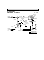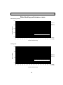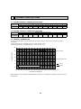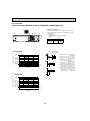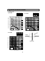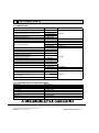
1
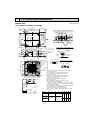
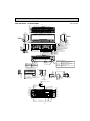
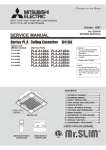
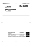
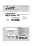
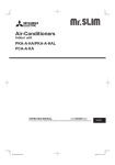
SPLIT-TYPE, HEAT PUMP AIR CONDITIONERS
March 2009
No. OCS15
TECHNICAL DATA BOOK
<Indoor unit>
[Model names]
HYPER HEATING INVERTER
PLA-A·BA
PKA-A·HA
PKA-A·HAL
PKA-A·KA
PKA-A·KAL
PCA-A·KA
<Outdoor unit>
[Model name]
PUZ-HA30NHA2
PUZ-HA36NHA2
CONTENTS
1. REFERENCE SERVICE MANUAL ············································· 2
2. SPECIFICATIONS ······································································ 3
3. OUTLINES AND DIMENSIONS ················································· 5
4. WIRING DIAGRAM··································································· 11
5. REFRIGERANT SYSTEM DIAGRAM ······································ 16
6. PERFORMANCE CURVES ······················································ 18
7. CORRECTION FACTORS ························································ 20
8. AIR FLOW DATA ······································································ 22
9. NOISE CRITERION CURVES ·················································· 29
10. OPTIONAL PARTS ·····················································Back cover
1
REFERENCE SERVICE MANUAL
For information on service, please refer to the service manual as follows.
1-1. INDOOR UNIT
Model name
Service Ref.
PLA-A18/30/36BA
PLA-A18BA1
Service
Manual No.
OCH420
OCB420
PLA-A30BA1
PLA-A36BA1
PKA-A18HA
PKA-A18HAL
PKA-A18HA
PKA-A18HAL
OCH456
OCB456
PKA-A30/36KA
PKA-A30/36KAL
PKA-A30/36KA.TH
PKA-A30/36KAL.TH
OCH457
OCB457
PCA-A30/36KA
PCA-A30/36KA
OCH455
OCB455
1-2. OUTDOOR UNIT
Model name
Service Ref.
PUZ-HA30/36NHA2
PUZ-HA30/36NHA2
2
Service
Manual No.
OCH426 OCB426
2
SPECIFICATIONS
Model name
Cooling
*1
Heating
*1
Heating at 17°F(-8.3°C)
*2
Heating at 5°F(-15°C)
*3
Power supply
Voltage
Indoor unit
Indoor unit
Outdoor unit
Max. Capacity
Rated Capacity
Min. Capacity
Total Input
EER
SEER
Moisture Removal
SHF
Max. Capacity
Rated Capacity
Min. Capacity
Total Input
COP
HSPF(4/5)
Max.Capacity
Total Input
COP
Max. Capacity
Total Input
COP
Phase, Cycle, Voltage
Breaker size
Indoor - Outdoor S1 - S2
Indoor - Outdoor S2 - S3
Indoor - Remote Controller
MCA
MOCP
Fan Motor
Fan Motor Output
Airflow DRY *4
Airflow WET *4
Airflow DRY *4
Airflow WET *4
External pressure
Sound level *4
External finish (Grille)
Dimension Unit (Grille)
Weight Unit(Grille)
Weight Unit(Grille)
Field drain pipe size
Remote Controller
Outdoor unit
MCA
MOCP
Fan Motor
Fan Motor Output
Compressor
Air flow
Refrigerant Control
Defrost Method
Sound level at cooling
Sound level at heating
External finish
Dimension
Refrigerant
Refrigerant pipe size
Refrigerant pipe length
Weight
Type
Charge
Oil
Gas side O.D.
Liquid side O.D.
Height difference
Length
Refrigerant Piping
Connection Method
BTU/h
BTU/h
BTU/h
W
BTU/h/W
BTU/h/W
Pints/h
BTU/h
BTU/h
BTU/h
W
W/W
BTU/h/W
BTU/h
W
W/W
BTU/h
W
W/W
A
A
A
F.L.A.
W
CMM
CMM
CFM
CFM
Pa
dB(A)
W : mm[inch]
D : mm[inch]
H : mm[inch]
kg
lbs
mm[inch]
A
A
F.L.A.
W
Type
R.L.A.
L.R.A.
CMM[CFM]
dB(A)
dB(A)
W : mm[inch]
D : mm[inch]
H : mm[inch]
kg[lbs]
kg[lbs, oz]
L[oz]
mm[inch]
mm[inch]
PLA-A36BA
PLA-A30BA
PUZ-HA36NHA2
PUZ-HA30NHA2
30,000
36,000
30,000
34,000
18,000
18,000
2,450
2,690
12.2
12.6
15.6
17.0
7.2
7.1
0.73
0.71
40,000
34,000
38,000
32,000
18,000
18,000
3,230
3,440
3.45
2.73
10.0 / 8.0
9.4 / 7.1
38,000
32,000
5,300
5,720
2.10
1.64
38,000
32,000
5,860
6,630
1.90
1.41
1phase, 60Hz, 208/230V
30
AC208/230V
DC24V
DC12V
2
1
15
1.00
0.51
120
50
20-23-26-30
14-16-18-21
19-22-25-29
13-15-17-20
710-810-920-1060
490-570-640-740
460-530-600-710
670-770-880-1030
0
28-30-32-34
32-34-37-40
White Munsell 6.4Y 8.9/0.4
840(950) [33-1/16(37-3/8)]
840(950) [33-1/16(37-3/8)]
258(35) [10-3/16(1-3/8)] 298(35) [11-3/4(1-3/8)]
23(6)
25(6)
55(13)
51(13)
O.D. 32 [1-1/4]
Attached in Grille
28
40
0.4 + 0.4
60 + 60
ANB33FJEMT
ANB33FJEMT
18
27.5
100[3,530]
Electronic Expansion Valve
Reverse Cycle
52
53
Ivory Munsell 3Y 7.8/1.1
950 [37-3/8]
330 + 30 [13 + 1-3/16]
1,350 [53-1/8]
120 [265]
R410A
5.5 [12 lbs]
1.4(FV50S) [45]
15.88 [5/8]
9.52 [3/8]
Max.30m [Max.100ft]
Max.75m [Max.245ft]
Not supplied
Flared
NOTES : *1.Rating conditions (cooling)-Indoor : D.B. 26.7°C(80°F), W.B. 19.4°C(67°F)
(heating)-Indoor : D.B. 21.1°C(70°F), W.B. 15.6°C(60°F)
*2.Conditions
(heating)-Indoor : D.B. 21.1°C(70°F), W.B. 15.6°C(60°F)
*3.Conditions
(heating)-Indoor : D.B. 21.1°C(70°F), W.B. 15.6°C(60°F)
Operating range
PKA-A36KA(L)
PKA-A30KA(L)
PUZ-HA36NHA2
PUZ-HA30NHA2
34,200
30,000
33,500
30,000
18,000
18,000
2,790
2,500
12.0
12.0
16.2
16.5
8.7
8.1
0.71
0.70
40,000
34,000
38,000
32,000
18,000
18,000
2,930
3,410
3.20
3.27
9.5 / 7.3
10.0 / 7.8
38,000
32,000
6,010
5,080
1.85
1.85
38,000
32,000
6,760
5,770
1.65
1.63
1phase, 60Hz, 208/230V
30
AC208/230V
DC24V
DC12V : Wired type
1
15
0.36
0.57
56
18-20-22
20-23-26
16-18-20
18-21-23
635-705-775
705-810-920
570-635-700
635-730-830
0
39-42-45
43-46-49
White Munsell 1.0Y 9.2/0.2
1170 [46-1/16]
295 [11-5/8]
365 [14-3/8]
21
46
I.D. 16 [5/8]
Attached in Indoor unit
28
40
0.4 + 0.4
60 + 60
ANB33FJEMT
ANB33FJEMT
18
27.5
100[3,530]
Electronic Expansion Valve
Reverse Cycle
52
53
Ivory Munsell 3Y 7.8/1.1
950 [37-3/8]
330 + 30 [13 + 1-3/16]
1,350 [53-1/8]
120 [265]
R410A
5.5 [12 lbs]
1.4(FV50S) [45]
15.88 [5/8]
9.52 [3/8]
Max.30m [Max.100ft]
Max.75m [Max.245ft]
Not supplied
Flared
Outdoor : D.B. 35°C(95°F), W.B. 23.9°C(75°F)
Outdoor : D.B. 8.3°C(47°F), W.B. 6.1°C(43°F)
Outdoor : D.B. -8.3°C(17°F), W.B. -9.4°C(15°F)
Outdoor : D.B. -15°C(5°F), W.B. -15°C(5°F)
Indoor intake air temperature
Outdoor intake air temperature
D.B. 46°C(115°F)
Maximum
D.B. 32°C(90°F), W.B. 23°C(73°F)
Minimum
D.B. 19°C(66°F), W.B. 15°C(59°F)
D.B. -18°C(0°F)*
Maximum
D.B. 28°C(83°F)
D.B. 21.1°C(70°F), W.B. 15°C(59°F)
Heating
Minimum
D.B. 17°C(63°F)
D.B. -25°C(-13°F), W.B. -25°C(-13°F)
* In case that the wind baffle is installed. (In case that the wind baffle is not installed, the minimum temperature will be -5°C(23°F)DB.)
Cooling
3
Model name
Cooling
*1
Heating
*1
Heating at 17°F(-8.3°C)
*2
Heating at 5°F(-15°C)
*3
Power supply
Voltage
Indoor unit
Indoor unit
Outdoor unit
Max. Capacity
Rated Capacity
Min. Capacity
Total Input
EER
SEER
Moisture Removal
SHF
Max. Capacity
Rated Capacity
Min. Capacity
Total Input
COP
HSPF(4/5)
Max. Capacity
Total Input
COP
Max. Capacity
Total Input
COP
Phase, Cycle, Voltage
Breaker size
Indoor - Outdoor S1 - S2
Indoor - Outdoor S2 - S3
Indoor - Remote Controller
MCA
MOCP
Fan Motor
Fan Motor Output
Airflow DRY (Lo-M2-M1-Hi)
Airflow WET (Lo-M2-M1-Hi)
Airflow DRY (Lo-M2-M1-Hi)
Airflow WET (Lo-M2-M1-Hi)
External pressure
Sound level (Lo-M2-M1-Hi)
External finish (Grille)
Dimension Unit (Grille)
Weight Unit(Grille)
Weight Unit(Grille)
Field drain pipe size
Remote Controller
Outdoor unit
MCA
MOCP
Fan Motor
Fan Motor Output
Compressor
Air flow
Refrigerant Control
Defrost Method
Sound level at cooling
Sound level at heating
External finish
Dimension
Refrigerant
Refrigerant pipe size
Refrigerant pipe length
Weight
Type
Charge
Oil
Gas side O.D.
Liquid side O.D.
Height difference
Length
BTU/h
BTU/h
BTU/h
W
BTU/h/W
BTU/h/W
Pints/h
BTU/h
BTU/h
BTU/h
W
W/W
BTU/h/W
BTU/h
W
W/W
BTU/h
W
W/W
1phase, 60Hz, 208/230V
30
AC208/230V
DC24V
DC12V
A
A
A
F.L.A.
W
CMM
CMM
CFM
CFM
Pa
dB(A)
PCA-A36KA
PUZ-HA36NHA2
36,000
34,000
18,000
2,810
12.1
16.6
8.2
0.73
40,000
38,000
18,000
3,270
3.41
10.3 / 8.2
38,000
5,720
1.95
38,000
6,550
1.70
PCA-A30KA
PUZ-HA30NHA2
30,000
30,000
18,000
2,480
12.1
16.1
8.3
0.69
34,000
32,000
18,000
2,990
3.14
9.3 / 7.2
32,000
5,170
1.81
32,000
5,830
1.61
2
1
15
0.97
160
22-24-26-28
20-22-24-26
775-850-920-990
705-775-850-920
0.54
95
16-17-18-20
15-16-17-19
565-600-635-705
530-565-600-670
0
35-37-39-41
37-39-41-43
White Munsell 6.4Y 8.9/0.4
1280 [50-3/8]
W : mm[inch]
D : mm[inch]
H : mm[inch]
kg
lbs
mm[inch]
1600 [63]
680 [26-3/4]
230 [9-1/16]
32
71
36
79
O.D. 26 [1-1/32]
Attached in Grille
28
40
0.4 + 0.4
60 + 60
ANB33FJEMT
18
27.5
100[3,530]
Electronic Expansion Valve
Reverse Cycle
52
53
Ivory Munsell 3Y 7.8/1.1
950 [37-3/8]
330 + 30 [13 + 1-3/16]
1,350 [53-1/8]
120 [265]
R410A
5.5 [12 lbs]
1.4(FV50S) [45]
15.88 [5/8]
9.52 [3/8]
Max.30m [Max.100ft]
Max.75m [Max.245ft]
Not supplied
Flared
A
A
F.L.A.
W
Type
R.L.A.
L.R.A.
CMM[CFM]
dB(A)
dB(A)
W : mm[inch]
D : mm[inch]
H : mm[inch]
kg[lbs]
kg[lbs, oz]
L[oz]
mm[inch]
mm[inch]
Refrigerant Piping
Connection Method
NOTES : *1.Rating conditions (cooling)-Indoor : D.B. 26.7°C(80°F), W.B. 19.4°C(67°F)
(heating)-Indoor : D.B. 21.1°C(70°F), W.B. 15.6°C(60°F)
*2.Conditions
(heating)-Indoor : D.B. 21.1°C(70°F), W.B. 15.6°C(60°F)
*3.Conditions
(heating)-Indoor : D.B. 21.1°C(70°F), W.B. 15.6°C(60°F)
Operating range
Outdoor : D.B. 35°C(95°F), W.B. 23.9°C(75°F)
Outdoor : D.B. 8.3°C(47°F), W.B. 6.1°C(43°F)
Outdoor : D.B. -8.3°C(17°F), W.B. -9.4°C(15°F)
Outdoor : D.B. -15°C(5°F), W.B. -15°C(5°F)
Indoor intake air temperature
Outdoor intake air temperature
D.B. 46°C(115°F)
Maximum
D.B. 32°C(90°F), W.B. 23°C(73°F)
Minimum
D.B. 19°C(66°F), W.B. 15°C(59°F)
D.B. -18°C(0°F)*
Maximum
D.B. 28°C(83°F)
D.B. 21.1°C(70°F), W.B. 15°C(59°F)
Heating
Minimum
D.B. 17°C(63°F)
D.B. -25°C(-13°F), W.B. -25°C(-13°F)
* In case that the wind baffle is installed. (In case that the wind baffle is not installed, the minimum temperature will be -5°C(23°F)DB.)
Cooling
4
OUTLINES AND DIMENSIONS
INDOOR UNIT
PLA-A18BA PLA-A30BA PLA-A36BA
Ceiling hole
33-27/32 to 35-13/16(860~910)
M
1-25/32
(20~45)
(
Connected the attached
flexible pipe or socket.
Burring hole
3-:1/8(3-:2.8)
6-9/16(167)
(:150)
Burring hole pitch
:4-29/32(:125)
120°
120°
( 158)
Cut out hole
:3-15/16(:100)
++
(35)
1-3/8
)
6-7/32
A
7-15/32
3-15/16 (100)
5-1/8 (130)
Burring hole
Detail drawing of fresh air intake hole
Ceiling
In case of standard grille
In case of wireless remote controller
Emergency operation switch<Cooling>
Auto vane
(Air outlet)
Emergency operation
switch<Heating>
Receiver
23-1/2 (597)
Air intake hole
Air outlet hole
14-:1/8 (14-:2.8)
(350)
Keep 25/64(10)to 19/32(15)
between unit ceiling
and ceiling slab.
Drain hole
Drain pump clean hole
and Drain emergency
drainage hole
M
19-11/16 (500)
+3/16
0
(17+5
0 )
Ceiling
Grille
23-1/2 (597)
Air intake hole
13-25/32
(:175) :6-7/8
Burring hole pitch
+
11/16
Suspension bolt
lower edge
37-3/8 (950)
Branch duct
hole
+
(50~70)
+
1-15/16~2-3/4
5-1/2
+ +
(140)
+
(170)
6-11/16
2
(190)
(377)
14-27/32
Ceiling hole
25/32 to
25/32
Drain pipe
connected to VP-25
4-1/8 (105)
11-3/16
+ +
6-9/64 (156)
(284)
2-3/8
Cut out hole
to 1-25/32
(20~45)
(5/16)
C
D
(60)
1
3-17/32 (90)
Cut out hole
(160)
33-1/16 (840)
3-15/16 (100)
3-15/16 (100)
3-17/32 (90)
:5-29/32
6-5/16
7-3/8
(187.5)
Suspension bolt
M10 or W3/8
Detail connecting of branch duct(Both aspects)
(7.5)
For wiring replacement kit
terminal block
24-13/32 (620)
15/16 (24)
6-5/16 (160)
Suspension bolt pitch
+35
23-13/16 -3/16
+1-3/8 (605 -5 )
Indoor unit/Outdoor unit
connecting terminal block
3-17/32 (90)
5-29/32(150)
33-1/16(840)
For MA-Remote controller
terminal block
Branch duct hole
(7.5)
(5/16)
(160)
B
6-5/16
25/32 to 1-25/32(20~45)
31-7/8(810)
Suspension bolt pitch
(160)
6-5/16
Fresh air
intake hole
33-27/32 to 35-13/16 (860~910)
25/32 to 1-25/32(20~45)
Unit: inch (mm)
6-3/32 (155)
3
Operation lamp
DEFROST/STAND BY lamp
(83)
M
M
(36)
Vane motor
1-27/64
3-17/64
Air intake grille
19-11/16 (500)
Corner pocket
Air outlet hole
37-3/8 (950)
1-27/64
3-17/64
(83)
Indoor unit
Ceiling
Grille
Min.94-1/2(2400)
from floor
Min.19-11/16(500)
Entire
periphery
Floor
(36)
Note1. As for drain pipe, please use VP-25(O.D. :32 PVC TUBE).
Drain pump is included.
Max. lifting height is 70-7/18(850mm) from the ceiling.
2. As for suspension bolt, please use M10 or W3/8.
(Procured at local site)
3. Electrical box may be removed for the service purpose.
Make sure to slack the electrical wire little bit for
control/power wires connection.
4. The height of the indoor unit can be adjusted
with the grille attached.
5. For the installation of the optional high efficiency filter
or optional multi-functional casement.
1) Add 5-5/16(135mm) to the dimensions + marked on the figure.
2) Optional high efficiency filter must be used jointly with optional
multi-functional casement.
6. When installing the branch ducts, be sure to insulate adequately.
Otherwise condensation and dripping may occur.
(It becomes the cause of dew drops/water dew.)
7. As for necessary installation/service space, please refer to the
left figure.
Models
PLA-A12BA
PLA-A18BA
PLA-A24BA
PLA-A30BA
PLA-A36BA
PLA-A42BA
5
1
2
Ref rigerant pipe
····: 6.35mm
Flared connection
····1/4
Ref rigerant pipe
····: 12.7mm
Flared connection
····1/2
Ref rigerant pipe
····: 9.52mm
Flared connection
····3/8
Ref rigerant pipe
····: 15.88mm
Flared connection
····5/8
A
B
C
D
9-1/2 10-3/16 3-5/32 2-29/32
(241) (258)
(80)
(74)
11-1/16 11-3/4 3-11/32 3-1/32
(77)
(281) (298) (85)
PKA-A18HAL
Unit: inch (mm)
15-3/16(387)
7-1/2(192)
7-3/4(197)
Top side
Mount board
23-9/16(599)
Front side
Right side
11-5/8(295)
D
Left side
A
27-1/16(688)
2-1/8
(55)
Knock out hole
for left piping
9-13/16(249)
6-1/16(155)
35-3/8(898)
3/16(5)
Knockout hole
for right piping
Front side(Grille open)
Sleeve
Through hole
(purchased locally)
:2-1/2~:3-1/8
:2-1/2~:3-1/8
(:65~:80)
(:65~:80)
Terminal block for indoor/outdoor
connecting line
Terminal block for power supply coption
Terminal block for
MA-remote controller
(only PKA-A·HA models)
17-15/16(457)Gas pipe
21-3/16(539)Liquid pipe
24(610)Drain hose
6-5/8(169)
6-3/16(158)
DEFROST/STAND BY lamp
Operation lamp
24-1/16(612)
5/16(8)
Emergency operation switch
(cooling/heating)
7-3/16(184)
Under side
Vane(auto)
Refrigerart Liquid pipe
Piping
Gas pipe
Knockout hole
for lower piping
Louver(manual)
C
1/4F (:6.35)
1/2F (:12.7)
Drain hose
Knock out hole
for lower piping
:5/8 (:16) O.D
Receiver
B
Center measurement hole :3/32(:2.5)
5/32(3.8)
12-7/8(237.5)
14(356.3)
14-5/8(372.3)
4-7/8(125)
Mount board
7-13/16(200)
8-13/16(225)
9-5/16(238)
10-3/8(265)
11-7/16(291.5)
2-1/4(58)
0
5/8(16)
1-1/16(28.5)
1-9/16(41)
3-1/16(78.5)
3-9/16(91)
4-1/16(103.5)
4-9/16(116)
6-1/2(166)
7(178.5)
8(203.5)
9-1/8(232.5)
9-15/16(253.5)
2-3/4(70)
0
2-3/4(70)
9/16(15)
0
9/16(15)
4-7/8(125)
8-13/16(225)
7-13/16(200)
77-:3/16(:5.1)
Tapping
screw hole
11-7/16(291.5)
10-3/8(265)
14-5/8(372.3)
14(356.3)
12-7/8(327.5)
4-:5/16(:9)
Bolt hole
Indoor unit outline
13/16(21.8)
0
3/4(20)
1-1/4(32.7)
2-1/16(53.5)
2-9/16(66)
5(128.5)
6(153.5)
11-1/16(281)
7-9/16(193.5)
Knockout hole for
rear piping
2-3/4×12-3/16(70×310)
4-1/2(115)
5-1/2(140)
6-9/16(167)
7-1/16(180.3)
10-15/16(278.3)
9-5/16(238)
8-3/8(213)
6-13/16(174)
15-1/2(394)
17-5/8(449)
0
17-5/8(449)
9-1/16(231.5)
Wall hole
for
left rear
piping
10-3/4(273.2)
Wall hole for
right rear piping
Required space(Indoor unit)
D
1-3/4(46)
2-5/16(60)
Min.1/4(7)
2-5/16(59)
1-11/16(43)
A
1-11/16(43)
1-11/16(43)
B
6
Min.1-31/32(50)
250mm,9-13/16inch or greater with
optional drain pump installation.
2-3/16(56)
C
1-11/16(43)
2-3/16(56)
1-3/4(46)
2-3/16(56)
7/16(12.5)
Air inlet
3/16(6)
2-11/16(69)
(mm)
Air inlet
Air outlet
Min.1-31/32(50)
Min.8-5/8
(220)
Min.5-7/8(150)
Min.9-13/16(250)
Knockout hole for piping
3/16(6)
PKA-A18HA
PKA-A30,36KA
PKA-A30,36KAL
Unit: inch (mm)
5-17/132(140.3)
2-9/16(65.2)
Top side
17(431.7)
7/16(11)
16-11/16(423.7)
Left side
Right side
Front side
14-3/8(365)
Mount board
Knock out hole
for left piping
C
2-29/32(74)
9-1/2(241)
33-21/32(855)
46-1/16(1170)
A
3/16(5)
11-5/8(295)
Operation lamp
Front side(Grille open)
Knock out hole
for right piping
DEFROST/STAND BY lamp
Receiver
2-3/32(53)
1-1/4(32)
23/32(18)
Terminal block for Outdoor unit
Terminal block for power supply (option)
Terminal block for
MA-remote controller (only PKA-A·KA models)
Emergency operation switch
(cooling/heating)
Filter hook
1-3/16(30)
1-3/8(35)
17-15/32(444)Gas pipe
2-19/32(66)
4-27/32(123)
18-31/32(482)Liquid pipe
23-1/32(585)Drain hose
6-1/16(154)
5-9/32(134)
Under side
Piping connection department
Vane(auto)
Louver(manual)
B
Liquid pipe
B
Knock out hole
for lower piping
Sleeve
(purchased locally)
:2-15/16
(:75)
Through hole
Gas pipe
:2-15/16~:3-5/32
(:75~:80)
Drain hose
Refrigerant pipe: 3/8 O.D(:9.52)
Flared connection: 3/8F
Refrigerant pipe: 5/8 O.D(:15.88)
Flared connection: 5/8F
5/8(:16) O.D
Required space(Indoor unit)
Min.2-27/32(72.4)
3-1/32(77)
3-7/16(87)
2-9/16(65)
13/32(10.7)
2-1/8(54)
1/8(3)
0
5/8(15.5)
31/32(25)
1-31/32(50)
2-15/16(75)
3-15/16(100)
4-19/32(117)
4-29/32(125)
5-19/32(142)
7-9/16(192)
9-17/32(242)
12-3/8(314)
14-11/32(364)
15-1/8(384.5)
16-3/32(408.5)
17-9/32(439)
17-7/8(454)
18-5/16(465.5)
4-11/32(110)
2-3/8(60)
13/32(10)
0
13/32(10)
2-3/8(60)
4-11/32(110)
12-3/8(314)
17-7/8(454)
17-9/32(439)
16-3/32(408.5)
15-1/8(384)
14-11/32(364)
20-3/8(517.4)
4-:11/32(:9) Bolt hole
Mount board
Indoor unit outline
2-1/8(54)
1-1/4(32)
31/32(25)
1/2(12.5)
0
1/2(12.5)
1-15/32(37.5)
2-15/32(62.5)
3-7/16(87.5)
4-1/8(104.5)
5-3/32(129.5)
0
6-9/16(167)
8-17/32(217)
9-1/32(229.5)
10-13/32(264)
11-1/2(292)
11(279.5)
11-1/2(292)
Wall hole for
right rear piping
7
23-1/32(585)
17-11/16(449.2)
13-11/32(339)
13-3/4(349.2)
15-1/8(384)
8-17/32(216.5)
0
7-7/16(189)
15-1/8(384)
13-11/32(339)
16-15/16(430.5)
Knockout hole for
rear piping
2-15/16×18-29/32(75×480)
37.5)
/32(R
R1-15
23-1/32(585)
12-5/32(308.5)
12-1/4(311)
Wall hole for
left rear piping
A
5/16(7.8)
B
Center measurement hole
:3/32(:2.5)
75-:3/16(:5.1)
Tapping
screw hole
3-1/32(77)
2-5/8(67)
2-9/16(65)
2-5/8(67)
3-1/32(77)
C
5/16(7.8)
Min.9-27/32(250)
Min.2(50.5)
Min.1-7/8(48)
Knockout hole for piping
Air outlet
Min.8-21/32(220)
20-7/8(530.5)
Min.9/32(7)
Air inlet
2-9/16(65)
7-1/2(190)
1-13/16(46)
1
2
3
4
5
6
7
8
3(76)
4-7/8(124)
8
120°
7
15-1/4(387)
1-1/2(38)
11/16(18)
10-1/4(260)
1-7/8(48)
9-11/16(246)
9-3/16(233)
Drainage
When drain socket
is installed
1/16(1)
Air intake
5-7/16(138)
1/16(2)
3-3/8(86)
3-3/8(85)
4
Drainage pipe connection(1(26mm)I.D.)
Drainage pipe connection(for the left arrangement)
Knockout hole for left drain-piping arrangement
Refrigerant-pipe connection(gas pipe side/flared connection)
Refrigerant-pipe connection(liquid pipe side/flared connection)
Knockout hole for upper drain pipe arrangement
Knockout hole for fresh air intake Φ3-15/16(Φ100)
Knockout hole for wiring arrangement Φ7/8(Φ22)
Accessory...Drain socket (1(26mm) I.D.)
2
18-1/8(461)
Ceiling
4-3/4(121)
In case of the rear pipe arrangement, make sure to
remove the shaded portions from the independent piece.
Then put the independent piece back in initial
position.(The heat exchanger might be clogged because of dust)
5/16(8)
When electrical box
is pulled down
2
Electrical box
2-15/16(75)
3
12
5)
Φ4
-15
/16
(Φ
4-15/16(126)
1-7/16(37)
1
7-1/12(190)
1/16(2)
Air outlet
47-3/16(1198)
46-3/16(1173)
50-3/8(1280)
48-11/16(1237) (Suspension bolt pitch)
5-7/8(150)
Electrical box
5
7-3/16(182)
5-1/2(140)
2-7/16(62)
1/16(2)
12-5/8(320)
3-3/8(85)
3-5/16(84)
10(254)
[FRONT VIEW]
3-1/8(80)
3-7/16(88)
2-1/4(57)
26-3/4(680)
7-11/16(195)
26-3/4(680)
8
18-3/4(476)
6
2(51)
9/16
14
DEFROST/STAND BY lamp
Receiver
Operation lamp
Emergency operation
switch <Heating>
When drain socket
is installed
Drainage
9-3/16(233)
liquid Φ3/8(Φ9.52)
gas Φ5/8(Φ15.88)
9-11/16(246)
7-7/8(200)
NOTES.
1.Use M10 or W3/8 screw for anchor bolt.
2.Please be sure when installing the drain lift up
mechanism(option parts),refrigerant pipe will be only upward.
i-see sensor
Emergency operation
switch <Cooling>
9-5/16(236)
7-1/16(180)
In case of wireless remote controller
and i-see sensor(Optional Parts)
In case of wireless
remote controller
and i-see sensor
(Optional Parts)
3/16(5)
3/8(10)
PCA-A30KA
Unit: inch (mm)
9-1/16(230)
11/16(18)
2
3
7-1/2(190)
1-13/16(46)
Ceiling
18-1/8(461)
4-3/4(121)
3(76)
4-7/8(124)
8
120°
5
7
15-1/4(387)
1-1/2(38)
11/16(18)
10-1/4(260)
3-3/8(85)
5-7/16(138)
1/16(2)
3-3/8(86)
6
7
8
5
1
2
3
4
1-7/8(48)
9-11/16(246)
9-3/16(233)
1/16(1)
Drainage
When drain socket
is installed
Electrical box
1/16(2)
7-1/2(190)
Drainage pipe connection(1(26mm)I.D.)
Drainage pipe connection(for the left arrangement)
Knockout hole for left drain-piping arrangement
Refrigerant-pipe connection
(gas pipe side/flared connection)
Refrigerant-pipe connection
(liquid pipe side/flared connection)
Knockout hole for upper drain pipe arrangement
Knockout hole for fresh air intake Φ3-15/16(Φ100)
Knockout hole for wiring arrangement Φ7/8(Φ22)
Accessory...Drain socket (1(26mm)I.D.)
2
5/16(8)
Air outlet
59-3/4(1518)
58-3/4(1493)
63(1600)
61-5/16(1557) (Suspension bolt pitch)
11/16(18)
5-7/8(150)
4
In case of the rear pipe arrangement, make sure to
remove the shaded portions from the independent piece.
Then put the independent piece back in initial
position.(The heat exchanger might be clogged because of dust)
When electrical box
is pulled down
2-15/16(75)
Electrical box
12
5)
Φ4
-15
/16
(Φ
4-15/16(126)
1-7/16(37)
7-3/16
182
5-1/2
140
NOTES.
1.Use M10 or W3/8 screw for anchor bolt.
2.Please be sure when installing the drain lift up
mechanism (option parts),refrigerant pipe will be only upward.
62
2-7/16
6
1/16(2)
3-3/8
85
3-5/16(84)
Air intake
10(254)
1
3-1/8
80
12-5/8(320)
3-7/16(88)
18-3/4(476)
[FRONT VIEW]
2(51)
9/16
14
liquid Φ3/8(Φ9.52)
gas Φ5/8(Φ15.88)
When drain socket
is installed
Drainage
9-3/16(233)
9-11/16(246)
7-7/8(200)
7-1/16(180)
9-5/16(236)
Emergency operation
switch <Heating>
DEFROST/STAND BY lamp
Receiver
Operation lamp
Emergency operation
switch <Cooling>
In case of wireless remote controller
and i-see sensor(Optional Parts)
In case of wireless
remote controller
and i-see sensor
(Optional Parts)
3/16(5)
3/8(10)
9-1/16(230)
26-3/4(680)
7-11/16(195)
2-1/4
57
9
26-3/4(680)
PCA-A36KA
Unit: inch (mm)
Min. 150mm
<5-29/32>
Min. 10mm
<3/8>
Service space
Min.
10mm<3/8>
:92
8>
<3-5/
92<3-5/8>
65<2-9/16>
Front piping hole
(Knockout)
45<1-25/32>
55<2-3/16>
63
<2-1/2>
27<1-1/16>
Front trunking hole 40<1-9/16>
(Knockout)
Conduit hole
(2-:27<1-1/16>Knockout)
Piping Knockout Hole Details
73<2-7/8>
23<29/32>
Min.
500mm
<19-11/16>
19<3/4>
:92
<3-5/8
>
40<1-9/16>
92<3-5/8>
45<1-25/32>
Conduit hole
(2-:27<1-1/16>Knockout)
92<3-5/8>
65<2-9/16>
:
<3-5 92
/8>
Rear piping hole
(Knockout)
74<2-19/32>
40<1-9/16>
2-:22.2<7/8>
Handle
1/2 Conduit attachment
When installing the conduit.
Set the attachment to the
inner side of each panel.
Handle
Handle
Side Air Intake
Rear Air Intake
Side Air Intake
Piping and wiring connections
can be made from 4 directions:
front, right, rear and below.
Rear trunking hole
(Knockout)
40<1-9/16>
Right trunking hole
(Knockout)
FOUNDATION
<Foundation bolt height>
Min.
30mm
<1-3/16>
Conduit hole
(2-:27<1-1/16>Knockout)
55<2-3/16>
75
<2-31/32>
Right piping hole
(Knockout)
Air intake
Handle
····Refrigerant GAS pipe connction (FLARE):15.88<5/8>
····Refrigerant LIQUID pipe connection (FLARE): 9.52<3/8>
*1 ····Indication of STOP VALVE connection location.
Example of Notes
Min. 1000mm
<39-3/8>
Min. 10mm
<3/8>
FREE
27<1-1/16>
92<3-5/8>
63<2-1/2>
73<2-7/8>
30<1-3/16>
220
<8-21/32>
66<2-5/8>
42<1-21/32>
Earth terminal
950<37-13/32>
Drain hole
5-:33<1-5/16>
71<2-13/16>
2
1
Handle
Service panel
Terminal Block
Left···Power supply wiring
Right····Indoor/Outdoor wiring
2-12%36 Oval hole
(Foundation Bolt M10<W3/8>)
145
145
145
<5-23/32> <5-23/32> <5-23/32>
322<12-11/16>
Air Discharge
175<6-7/8>
175<6-7/8>
600<23-5/8>
2-U Shaped notched hole
(Foundation Bolt M10<W3/8>)
Rear Air Intake
Front piping cover
Bottom piping hole
(Knockout)
Rear piping cover
PUZ-HA36NHA2
23<29/32>
Please secure the unit firmly
with 4 foundation (M10<W3/8>)
bolts. (Bolts and washers must
be purchased locally.)
55<2-3/16>
27<1-1/16>
1350<53-5/32>
Min.
150mm
<5-29/32>
Min.
500mm
<19-11/16>
3 FOUNDATION BOLTS 4 PIPING-WIRING DIRECTIONS
* 1 443<17-7/16>
330<13>
30<1-3/16>
23<29/32>
45<1-25/32>
Dimensions of space needed
for service access are
shown in the below diagram.
31<1-7/32>
* 1 447<17-19/32>
The diagram below shows a
basic example.
Explantion of particular details are
given in the installation manuals etc.
73<2-7/8>
63<2-1/2>
23<29/32>
635<25>
371<14-19/32>
219<8-5/8>
417<16-13/32>
1 FREE SPACE (Around the unit) 2 SERVICE SPACE
71<2-13/16>
10
81<3-3/16>
56<2-7/32>
19<3/4>
370<14-9/16>
28<1-3/32>
53<2-3/32>
1076<42-3/8>
PUZ-HA30NHA2
Unit : mm<inch>
4
WIRING DIAGRAM
PLA-A18BA PLA-A30BA PLA-A36BA
[LEGEND]
SYMBOL
I.B
CN2L
CN24
CN30
CN32
CN41
CN51
DSA
FUSE
LED1
LED2
LED3
SW1
SW2
SWE
X1
ZNR01, 02
DP
FS
NAME
INDOOR CONTROLLER BOARD
CONNECTOR (LOSSNAY)
CONNECTOR<BACK-UP HEATING>
CONNECTOR<LLC>
CONNECTOR (REMOTE SWITCH)
CONNECTOR (HA TERMINAL-A)
CONNECTOR (CENTRALLY CONTROL)
SURGE ABSORBER
FUSE (T6.3AL250V)
POWER SUPPLY (I.B)
POWER SUPPLY (R.B)
TRANSMISSION (INDOOR-OUTDOOR)
SWITCH (MODEL SELECTION) +See table 1.
SWITCH (CAPACITY CODE) +See table 2.
CONNECTOR (EMERGENCY OPERATION)
RELAY (DRAIN PUMP)
VARISTOR
DRAIN-UP MACHINE
DRAIN FLOAT SWITCH
SYMBOL
MF
MV
TB4
TB5, TB6
NAME
FAN MOTOR
VANE MOTOR
TERMINAL BLOCK (INDOOR/OUTDOOR CONNECTING LINE)
TERMINAL BLOCK (REMOTE CONTROLLER
TRANSMISSION LINE)
ROOM TEMP. THERMISTOR
(32˚F/15kΩ, 77˚F/5.4kΩ DETECT)
PIPE TEMP. THERMISTOR/LIQUID
(32˚F/15kΩ, 77˚F/5.4kΩ DETECT)
COND. / EVA. TEMP. THERMISTOR
(32˚F/15kΩ, 77˚F/5.4kΩ DETECT)
TH1
TH2
TH5
OPTION PART
W.B
BZ
LED1
LED2
RU
SW1
SW2
PCB FOR WIRELESS REMOTE CONTROLLER
BUZZER
LED (OPERATION INDICATION: GREEN)
LED (PREPARATION FOR HEATING: ORANGE)
RECEIVING UNIT
EMERGENCY OPERATION (HEAT/DOWN)
EMERGENCY OPERATION (COOL/UP)
TB5
2
1
TRANSMISSION
WIRES
DC12V
2 1
TB6
Refer to tables 1 and 2.
R.B
I.B
VANE CNV(WHT)
20 18 16 14 12 10 8 6 4 2
SW1
J41 J42
SW2
19 17 15 13 11 9 7 5 3 1
Pair No.
5
CN2L
LED3
LED2
LED1
OUTDOOR 1 3 5
CN01
CN32
(WHT) 1
3
CN51(WHT) CN24(YLW)
CN41(WHT)
2 1
4
SWE
(BLU)
12
REMOCON
CN22
1
DSA
INDOOR/OUTDOOR
COMMUNICATION
CN3C
2 1
1
(BLK)
1 3
FUSE
ZNR02 U
DC280V
U
ZNR01
RECTIFICATION
(BLU)
ON OFF
1
3
CN3G
(BLK)
1
WIRELESS
CN90
(WHT)
9
I-SEE
SENSOR
CN4Y
1 (WHT) 4
I-SEE
SENSOR MOTOR
CN6Y
1 (RED) 6
CNAC
(WHT)
3 1
FLOAT SW LIQUID/PIPE INTAKE
CN4F
CN44
CN20 CN30
(WHT)
(WHT)
(RED) (GRN)
1
4
1
4
1 2
1
3
7
FAN
CNMF
(WHT)
4
X1
1
3
1 D.U.M
CNP
(BLU)
5
5
5
5
M
M
M
M
MV
MV
MV
MV
GRILLE
CNB
BZ
LED2
SW1
LED1
SW2
ON
OFF
I-SEE
SENSOR
FS
M
t˚
t˚
TH2 TH5
t˚
TH1
MS
3~
MF
TB4
YLW S1
ORN S2
S3
+1
TO
OUTDOOR
UNIT
ORN
BRN
M
1~
DP
+Be sure to turn off the power source
and then disconnect fan motor connector.
(Failure to do so will cause trouble in fan motor.)
MT
I-SEE SENSOR
CORNER PANEL
(OPTIONAL PART)
RU
W.B
<Table 1>SW1(MODEL SELECTION)
SW1
Service
1 2 3 4 5
5
4
9
YLW
ORN
<Table 2>SW2(CAPACITY CODE)
SW2
MODELS
Service
MODELS
PLA-A12BA
PLA-A18BA
PLA-A24BA
1 2 3 4 5
1 2 3 4 5
1 2 3 4 5
ON PLA-A30BA
OFF
ON PLA-A36BA
OFF
ON PLA-A42BA
OFF
Service
1 2 3 4 5
1 2 3 4 5
1 2 3 4 5
ON
OFF
ON
OFF
ON
OFF
Notes: 1. SymboIs used in wiring diagram above are,
: Connector,
: Terminal block.
2. Indoor and outdoor connecting wires have poIarities, make sure to match terminal numbers (S1, S2, S3) for correct wiring.
3. Since the outdoor side electric wiring may change, be sure to check the outdoor unit electric wiring for servicing.
+1. Use copper supply wires.
[Self-diagnosis]
1. For details on how to operate self-diagnosis with the wireless remote control, refer to the technical manuals etc.
2. For the wired remote control: When you quickly press twice the CHECK switch on the remote control, the unit begins self-diagnosis,
and Check Codes generated in the past appear on the display.
11
PKA-A18HA
PKA-A18HAL
[Explanation of symbols]
Symbol
I.B
CN2L
CN30
CN32
CN41
CN51
CN90
CN152
DSA
FUSE
LED1
LED2
LED3
SW1
SW2
SWE
ZNR01,02
R.B
TB6
Symbol
Name
M
Indoor controller board
MS
Connector (LOSSNAY)
S.W
Connector (LLC)
Connector ( Remote switch)
SWE2
Connector (HA terminal-A)
TB2
Connector (Centrally control)
TB4
Connector (Remote operation adapter)
TB5
Connector (Back-up heating)
TH1
Surge absorber
FUSE(T3.15AL250V)
TH2
Power supply (I.B)
Power supply (R.B)
TH5
Transmission (Indoor-outdoor)
W.B
Switch (Model selection) +See table 1
LED1
Switch (Capacity code) +See table 2
LED2
Connector (Emergency operation)
Varistor
REC1
Wired remote controller
Terminal block (Remote controller transmission line)
Name
Vane motor
Fan motor
Switch board
Emergency operation
Terminal block(Indoor unit Power (option))
Terminal block (Indoor/outdoor connecting line)
Terminal block (Remote controller transmission line)
Room temp. Thermistor
(32°F/15ΚΩ, 77°F/5.4ΚΩ Detect)
Pipe temp. Thermistor/liquid
(32°F/15ΚΩ, 77°F/5.4ΚΩ Detect)
Cond./eva. temp. Thermistor
(32°F/15ΚΩ, 77°F/5.4ΚΩ Detect)
Pcb for wireless remote controller
LED (Operation indication: Green)
LED (Preparation for heating: Orange)
Receiving unit
MS
3~
<Table 1>
SW1
(MODEL SELECTION)
I.B
CNMF
6
(WHT) FUSE
1
T11
DB1
ZNR01
U
SWE
ON
OFF
LED2
Refer to
tables
1and 2
1 2
CN2L
(RED)
1
1
CN151
(WHT)
5
1
X1
9
CN90
(WHT)
CN41
(WHT)
4
BLK
1 CN32 3
(WHT)
1
CN51
(WHT)
1 CN30 3
(BLK)
CN44
CN4F
(WHT)
(WHT)
1
4
1
4
5
MODELS
3
1
CNP(BLU)
CN3C 3
(BLU) 1
ORN
BRN
CNRU
(WHT)
2
S.W
1 2 3 4 5
A18
W.B
6
RU
LD101(B) REC1
LED1
ON
OFF
ON
OFF
R.B
BLU
CN22 1
(BLU) 2
SETTING
1 2 3 4 5
A12
LDSWE(B) SWE2
LDSWE(A)
(BLU)
ON
OFF
<Table 2>
SW2(CAPACITY CODE)
10
CN152
(WHT)
CN20
(RED)
1 2
1 2 3 4 5
DSA
LED3
1
SETTING
TB4 <+3>
YLW
TO
S1
ORN
OUTDOOR
S2
UNIT
S3
YLW
ORN
CN01
(BLK)
ZNR02
U
LED1
1
3
5
BLU
LED2
1
2
TB6
1
2
TB5
For PKA-A.HA
M
t
○
t
○
TH1
t
+1(Fig. 1)
CN01
I.B
(BLK)
YLW
1
ORN
3
5
○
TH2 TH5
Notes:
1.SymboIs used in wiring diagram above are,
: Connector,
: Terminal (block).
2.Indoor and outdoor connecting wires have poIarities, make sure to match terminal
numbers (S1, S2, S3)for correct wirings.
3.Since the outdoor side electric wiring may change, be sure to check the outdoor unit
electric wiring diagram for servicing.
4.This diagram shows the wiring of indoor and outdoor connecting wires.(specification of
230V), adopting superimposed system for power and signal.
+1: If indoor and outdoor units have separate power supplies, refer to Fig 1.
+2: For power supply system of this unit, refer to the caution label located near this diagram.
+3: Use copper supply wires.
12
I.B
RED
BLU
GRN/YLW
YLW
ORN
ORN
BRN
TB2
L1
L2
GR
POWER SUPPLY
208/230V 60Hz
TB4
S1
S2
S3
INDOOR/OUTDOOR
1 3
COMMUNICATION
CN3C(BLU)
TO OUTDOOR
UNIT
PKA-A30KA PKA-A30KAL
PKA-A36KA
PKA-A36KAL
Notes:
1.SymboIs used in wiring diagram above are,
: Connector,
: Terminal (block).
2.Indoor and outdoor connecting wires have poIarities, make sure to match terminal
numbers (S1, S2, S3)for correct wirings.
3.Since the outdoor side electric wiring may change, be sure to check the outdoor unit
electric wiring diagram for servicing.
4.This diagram shows the wiring of indoor and outdoor connecting wires.(specification of
230V), adopting superimposed system for power and signal.
+1: If indoor and outdoor units have separate power supplies, refer to Fig 1.
+2: For power supply system of this unit, refer to the caution label located near this diagram.
+3: Use copper supply wires.
13
PCA-A30KA
PCA-A36KA
[LEGEND]
SYMBOL
I.B
CN2L
CN24
CN30
CN32
CN41
CN51
DSA
FUSE
LED1
LED2
LED3
SW1
SW2
SWE
X1
ZNR01,02
R.B
MF
MV
NAME
INDOOR CONTROLLER BOARD
CONNECTOR (LOSSNAY)
CONNECTOR (BACK-UP HEATING)
CONNECTOR (LLC)
CONNECTOR (REMOTE SWITCH)
CONNECTOR (HA TERMINAL-A)
CONNECTOR (CENTRALLY CONTROL)
SURGE ABSORBER
FUSE (T6.3AL250V)
POWER SUPPLY (I.B)
POWER SUPPLY (R.B)
TRANSMISSION (INDOOR-OUTDOOR)
SWITCH (MODEL SELECTION) +See table 1
SWITCH (CAPACITY CODE) +See table 2
CONNECTOR (EMERGENCY OPERATION)
RELAY (DRAIN LIFT UP MECHANISM)
VARISTOR
WIRED REMOTE CONTROLLER BOARD
FAN MOTOR
VANE MOTOR
SYMBOL
TB4
TB5,TB6
TH1
TH2
TH5
OPTIONAL PARTS
W.B
BZ
LED1
LED2
RU
SW1
SW2
DP
FS
NAME
TERMINAL BLOCK (INDOOR/OUTDOOR CONNECTING LINE)
TERMINAL BLOCK (REMOTE CONTROLLER
TRANSMISSION LINE)
ROOM TEMP. THERMISTOR
(32ºF / 15kΩ, 77ºF/ 5. 4kΩ DETECT)
PIPE TEMP. THERMISTOR/LIQUID
(32ºF / 15kΩ, 77ºF/ 5. 4kΩ DETECT)
COND. / EVA. TEMP. THERMISTOR
(32ºF / 15kΩ, 77ºF/ 5. 4kΩ DETECT)
PCB FOR WIRELESS REMOTE CONTROLLER
BUZZER
LED (OPERATION INDICATION : GREEN)
LED (PREPARATION FOR HEATING : ORANGE)
RECEIVING UNIT
EMERGENCY OPERATION (HEAT / DOWN)
EMERGENCY OPERATION (COOL / UP)
DRAIN LIFT UP MECHANISM
DRAIN FLOAT SWITCH
<Table 1>SW1(MODEL SELECTION)
SW1
Service
Refer to tables 1 and 2
TB5
2
1
2 1
TB6
VANE CNV(WHT)
SW1
20 18 16 14 12 10 8 6 4 2
CN32
(WHT) 1
J41 J42
SW2
19 17 15 13 11 9 7 5 3 1
Pair No.
CN51(WHT)
5
CN2L
LED3
LED2
2 1
LED1
WIRELESS
CN90
(WHT)
9
9
CNB
SW1
M
MV
BZ
LED2
I-SEE
SENSOR
CN4Y
(WHT)
1
4
I-SEE
SENSOR MOTOR
CN6Y
(RED)
1
4
5
I-SEE
SENSOR
M
6
4
SW2
PCA-A30KA
1 2 3 4 5
1 2 3 4 5
ON PCA-A36KA
OFF
ON PCA-A42KA
OFF
OUTDOOR 1 3 5
CN01
1 3
(BLK)
INDOOR/OUTDOOR
COMMUNICATION
CN3C
(YLW)
2 1
DSA
ZNR02
(BLU)
U
1 2
REMOCON
CN22
ZNR01
DC294~325V
RECTIFICATION
(BLU)
ON OFF
FLOAT SW
CN4F
(WHT)
1
LIQUID/PIPE INTAKE
CN44
CN20 CN30
(WHT)
(RED) (GRN)
4
4
1 2
t°
t°
TH2 TH5
t°
TH1
1
FUSE
U
1
3
7
FAN
CNMF
(WHT)
4
MS
LED1
RU
W.B
(OPTIONAL PARTS)
PCA-A24KA
3
CN24
1
When attaching
When attaching
drain lift up
drain lift up
mechanism
mechanism
(optional parts),
(optional parts)
remove the jumper
1
connector CN4F FLOAT SW
CN4F
and fit the drain
FS
(WHT)
float switch (FS).
MT
I-SEE SENSOR
(OPTIONAL PARTS)
<Table 2>SW2(CAPACITY CODE)
SW2
Service
MODELS
MODELS
1
CN41(WHT)
SWE
(RED)
5
ON
OFF
R.B
I.B
1
1 2 3 4 5
TRANSMISSION
WIRES
DC12V
3~
MF
X1
1 D.U.M
1 3
CNP
(BLU)
1 2 3 4 5
TB4
YLW S1
ORN S2
S3
+1
TO OUTDOOR
UNIT
ORN
BRN
M
1~
DP
(OPTIONAL PARTS)
+Be sure to turn off the source power
and then disconnect fan motor connector.
(Failure to do so will cause trouble in Fan motor)
4
Service
1 2 3 4 5
YLW
ORN
ON
OFF
ON
OFF
Notes: 1.SymboIs used in wiring diagram above are,
: Connector
: Terminal block.
2. Indoor and outdoor connecting wires have poIarities, make sure to match terminal numbers (S1, S2, S3) for correct wirings.
3.Since the outdoor side electric wiring may change, be sure to check the outdoor unit electric wiring for servicing.
+1: Use copper supply wire.
14
PUZ-HA36NHA2
NAME
Terminal Block<Power Supply, Indoor/Outdoor >
Motor for Compressor
Fan Motor
Solenoid Valve (Four-Way Valve)
High Pressure Switch
Low Pressure Switch
Solenoid Valve (Bypass Valve)
Thermistor<Outdoor Pipe>
Thermistor<Discharge>
Thermistor<Outdoor 2-Phase Pipe>
Thermistor<Outdoor>
Thermistor<Heatsink>
Electronic Expansion Valve
Reactor
Active Filter Module
Main Smoothing Capacitor
Capacitor
SYMBOL
P.B.
TABU/V/W
TABS/T
TABP1/P2/P
TABN1/N2/N
DS2, DS3
IPM
N.F.
LI / LO
NI / NO
EI, E2
52C
C.B.
SW1
NAME
Power Circuit Board
Connection Terminal<U/V/W-Phase>
Connection Terminal <L/N-Phase>
Connection Terminal<DC Voltage>
Connection Terminal<DC Voltage>
Diode Bridge
Power Module
Noise Filter Circuit Board
Connection Terminal<L-Phase>
Connection Terminal<N-Phase>
Connection Terminal<Ground>
52C Relay
Controller Circuit Board
Switch<Forced Defrost, Defect History Record
Reset, Refrigerant Address>
Switch<Test Operation>
Switch<Function Switch>
SW4
SW5
SYMBOL
SW6
SW7
SW8
SW9
SWP
CN31
SS
CNM
CNMNT
NAME
Switch<Model Select>
Switch<Function Setup>
Switch<Function Setup>
Switch
Switch<Pump Down>
Connector<Emergency Operation>
Connector<Connection for Option>
Connector<A-Control Service Inspection Kit>
Connector
<Connected to Optional M-NET Adapter Board>
Connector
CNVMNT
<Connected to Optional M-NET Adapter Board>
Connector < Connected for Option (Contact Input)>
CNDM
Connector
< Connected for Option (Signal output)>
CN51
LED<Operation Inspection Indicators>
LED1,LED2
Fuse< T6.3AL250V>
F1~F4
X51,X52,X55 Relay
When M-NET adapter is connected
LEV-C
63L
LEV-A
LEV-B
M
M
TH33 TH32 TH7 TH6 TH3 TH4
M
5
C. B.
t°
t°
3
1 2
t°
t°
t°
12
2 1
CNF2
(WHT)
1
63L
(RED)
3
63H
(YLW)
3
TRANS
2
1
3
LEV-A
(WHT)
6
LEV-B
(RED)
1
F1
3
1
LEV-C
(BLU)
6
X52
1
2
3
1 SV2
3
(BLU)
21S4
1
SW1
SW12
LED3
+1
LED4
2
1
M-NET ADAPTER
CN2M
(WHT)
CND
(WHT)
3 1
CN31
1 2
21S4 3
(GRN)
F4
4
14
7
2
3
1
5
CN52C
(RED)
2 1
7
1
CNM
(WHT)
5
F3
CNAC
(WHT)
3
CNVMNT CNMNT
(WHT) (WHT)
1
2
F2
1
CN4
(WHT)
CN2
(WHT)
CNDC 1
(PNK)
CNS
(WHT)
1
X55
MF2 1
MS
3~
1
6
SW1 SW6
1
CN51 CNDM
(WHT) (WHT)
4
X51
1
SW4 SWP SW8 SW5
+1
1
TH33 TH32 TH7/6 TH3 TH4
(YLW) (BLK) (RED) (WHT) (WHT)
7
5
5
t°
LED1
MF1 1
MS
3~
CNF1
(WHT)
LED2
7
SW11
CN5
(WHT)
1
LED2
5
3
SW9 SW7
63H
LED1
[LEGEND]
SYMBOL
TB1
MC
MF1, MF2
21S4
63H
63L
SV
TH3,TH32,TH33
TH4
TH6
TH7
TH8
LEV-A, LEV-B,LEV-C
DCL
ACTM
CB
CY1, CY2
LED5
PUZ-HA30NHA2
3
1
3
A B S
TB7
1
M-NET
5
SS
(WHT)
SV
BLU
WHT
N. F.
LO
NO
2
52C
1
2
CN52C
(BLK)
P. B.
1
CNAF
(WHT)
CNDC
(PNK) 2
6
1
TABN1
BLK
2
1
W
BLK
L2
1
P
N1
N2
BLK
6
RED
L1
L2
GR
+1MODEL SELECT
36N
ON
OFF
ON
OFF
SW5-6 +2
1 2 3 4 5 6 7 8
1 2 3 4 5 6 7 8
+2. SW5 -1 to 5 : Function Switch
15
ON
OFF
ON
OFF
BLU
BRN
ORN
S2
S3
CY1
CY2
TB1
INDOOR
UNIT
ACTM
SW6
S1
U
WHT
Io
MODEL
NI
RED
L1
RED
4
GRN
YLW
MC
DCL
30N
U
LI
BLU
MS
3~
CN5
(RED)
1
CNAC1
(WHT)
WHT
V
TABN2
2
M-NET ADAPTER
NAME
Terminal Block<M-net connection>
Connector<Transmission>
Connector<Power Supply>
Connector<M-NET communication>
Switch<Status of communication>
Switch<Address setting : 1s digit>
Switch<Address setting : 10s digit>
LED<Power Supply : DC5V>
LED<Connection to Outdoor Unit>
LED<Transmission : Sending>
LED<Transmission : Recelving>
LED<Power Supply : DC12V>
BLK
E2
U
3
U
SYMBOL
TB7
CN5
CND
CN2M
SW1
SW11
SW12
LED1
LED2
LED3
LED4
LED5
CNAC2
(RED)
WHT
RED
1
2
1
2
TABP
WHT
BLK
WHT
CB
CN5
(RED)
CN4
(WHT)
TABN
TABS
1
TABW
2
7
1 CN3
2 (WHT)
DS2
TABP1 RED
WHT TABV
BLK
t° 2
TABP2
TH8
BLU
3
IPM
RED
CN2
(WHT)
TABT
3
1
RED TABU
7
DS3
RED
4
1 2 3 4 5 6
1 2 3 4 5 6
POWER SUPPLY
208/230V 60Hz
+Use copper supply wires.
EI
5
REFRIGERANT SYSTEM DIAGRAM
5-1. INDOOR UNIT
PLA-A·BA
PCA-A·KA
Strainer(#50)
Heat exchanger
Refrigerant GAS pipe connection
(Flare)
Thermistor TH5
(Cond./Eva. temperature)
Refrigerant flow in cooling
Refrigerant flow in heating
Refrigerant LIQUID pipe connection
(Flare)
Distributor
with strainer(#50)
Thermistor TH2
Pipe temperature (Liquid)
Thermistor TH1
(Room temperature)
PKA-A·HA
Strainer(#50)
PKA-A·HAL
PKA-A·KA
PKA-A·KAL
Strainer (#50)
Heat exchanger
Refrigerant GAS pipe connection
(Flare)
Thermistor TH2
Pipe temperature(Liquid)
Thermistor TH5
(Cond./ Eva.temperature)
Refrigerant flow in cooling
Refrigerant flow in heating
Refrigerant LIQUID pipe connection
(Flare)
Thermistor TH1
(Room temperature)
Strainer (#50)
Distributor
with strainer
(#50/#50 : HA(L))
(#50/#100 : KA(L))
16
5-2. OUTDOOR UNIT
PUZ-HA30NHA2 PUZ-HA36NHA2
unit : mm (inch)
Heat exchanger
Refrigerant
GAS pipe
connection
:15.88 (5/8)
Thermistor
TH6
(Outdoor
2-phase pipe)
Solenoid valve
(Four-way valve)
Ball valve
Strainer
#50
Charge plug
(High pressure)
Charge plug
(Low pressure)
Muffler
Low pressure
switch 63L
Thermistor TH3
(Outdoor pipe)
High pressure
switch 63H
Thermistor
TH32
(Outdoor pipe)
Strainer
#100
Strainer
#100
Electronic
expansion valve B
Refrigerant
LIQUID pipe
connection
:9.52
Strainer
(3/8)
#100
Stop valve
(with service port)
Thermistor TH7
(Outdoor)
Distributor
Thermistor TH33
(Outdoor pipe)
Strainer
#100
Thermistor TH4
(Discharge)
Electronic expansion valve A
Strainer
#100
Compressor
Power
receiver
Electronic
expansion valve C
Bypass
valve
Injection port
Heat inter change circuit
Replace
filter
Restrictor
Strainer
valve
#100
Refrigerant flow in cooling
Refrigerant flow in heating
17
6
PERFORMANCE CURVES
FOR THE COMBINATION OF OUTDOOR UNIT PUZ-HA·NHA2
Cooling performance curve
CAPACITY (RATIO)
1.4
1.2
INDOOR
W.B.
72°F (22°C)
1.0
68°F (20°C)
64°F (18°C)
61°F (16°C)
0.8
INDOOR
W.B.
72°F (22°C)
68°F (20°C)
64°F (18°C)
61°F (16°C)
1.2
TOTAL INPUT (RATIO)
1.0
0.8
0.6
0.4
23
30
(-5°C) (-1°C)
50
(10°C)
70
(21°C)
90
(32°C)
110
(43°C)
OUTDOOR D.B.(°F)
Note : This diagram shows the case where the operation frequency of a compressor is fixed.
18
Rated heating performance curve
Rated heating capacity
1.40
60˚F (16˚C)
70˚F (21˚C)
CAPACITY (RATIO)
1.20
80˚F (27˚C)
1.00
0.80
Indoor intake air dry-bulb temperature (˚F DB)
0.60
-15
-10
-5
0
5
-26
-23
-21
-18
-15
10
15
20
25
30
35
40
45
50
55
-12
-9
-7
-4
-1
2
4
7
10
13
(˚FWB)
16 (˚CWB)
60
Outdoor ambient temp.
Heating input
2.00
INPUT (RATIO)
1.50
80˚F (27˚C)
70˚F (21˚C)
60˚F (16˚C)
1.00
Indoor intake air dry-bulb temperature (˚F DB)
0.50
-15
-10
-5
0
5
-26
-23
-21
-18
-15
10
15
20
25
30
35
40
45
50
55
60
-12
-9
-7
-4
-1
2
4
7
10
13
16
Outdoor ambient temp.
19
(˚FWB)
(˚CWB)
CORRECTION FACTORS
7
7-1. COOLING CAPACITY CORRECTION FACTORS
Outdoor unit
PUZ-HA30NHA2
PUZ-HA36NHA2
Refrigerant piping length (one way)
5m (16ft)
1.00
10m (33ft) 20m (70ft) 30m (100ft) 40m (130ft) 50m (165ft) 55m (180ft) 60m (195ft) 70m (230ft) 80m (260ft)
0.985
0.957
0.931
0.908
0.886
0.876
0.865
0.846
0.829
7-2. HEATING CAPACITY CORRECTION FACTORS
Outdoor unit
PUZ-HA30NHA2
PUZ-HA36NHA2
Refrigerant piping length (one way)
5m (16ft)
1.00
10m (33ft) 20m (70ft) 30m (100ft) 40m (130ft) 50m (165ft) 55m (180ft) 60m (195ft) 70m (230ft) 80m (260ft)
0.997
0.991
0.985
0.979
0.973
0.970
0.967
0.961
0.955
7-3. CAPACITY CORRECTION
Cooling and heating capacity is lowered according to pipe length. Capacity can be obtained by referring to the capacity
curves below.
Corrected pipe length (m) = actual pipe length (m) + number of bends x 0.3 (m)
Corrected pipe length (ft) = actual pipe length (ft) + number of bends x 1 (ft)
100
Heating HA30,36
Capacity ratio [%]
95
90
85
Cooling HA30,36 model
80
Cooling
75
Heating
Note: The permitted pipe length is up to 80m<260ft>.
70
5
10 15 20 25 30 35 40 45 50 55 60 65 70 75 80
m
<16> <33> <50> <70> <80> <100> <115> <130><150><165><180><195><215><230><245><260> <ft>
Corrected pipe length [m]
When HAs pipe is one size larger than standard size, capacity can be obtained by referring to capacity curves of
standard size.
20
7-4. ADDITION OF REFRIGERANT
• Additional charging is not necessary if the pipe length does not exceed 30 m (100 ft).
• If the pipe length exceeds the specified length above, charge the unit with additional R410A refrigerant according to the
permitted pipe lengths in the chart below.
* When the unit is stopped, charge the unit with the additional refrigerant through the liquid stop valve after the pipe
extensions and indoor unit have been vacuumized.
* When the unit is operating, add refrigerant to the gas check valve using a safety charger. Do not add liquid refrigerant
directly to the check valve.
* After charging the unit with refrigerant, note the added refrigerant amount on the service label (attached to the unit).
• Be careful when installing multiple units. Connecting to an incorrect indoor unit can lead to abnormally high pressure and have
a serious effect on operation performance.
Model Max. pipe Max. height 30 m
length
difference
100 ft
0 oz
75 m
30 m
HA30,36
0 kg
245 ft
100 ft
Additional refrigerant charging amount
33 m 37 m 40 m 43 m 46 m 49 m 52 m 55 m 58 m 61 m 64 m 67 m 70 m 73 m 75 m
110 ft 120 ft 130 ft 140 ft 150 ft 160 ft 170 ft 180 ft 190 ft 200 ft 210 ft 220 ft 230 ft 240 ft 245 ft
6 oz 12 oz 18 oz 24 oz 30 oz 36 oz 42 oz 48 oz 54 oz 60 oz 66 oz 72 oz 78 oz 84 oz 86 oz
0.2 kg 0.4 kg 0.5 kg 0.7 kg 0.9 kg 1.0 kg 1.2 kg 1.4 kg 1.5 kg 1.7 kg 1.9 kg 2.0 kg 2.2 kg 2.3 kg 2.4 kg
21
8
AIR FLOW DATA
8-1. OUTLET AIR SPEED AND COVERAGE RANGE
Airflow
CFM
Air speed
ft/sec.(m/sec.)
Coverage range
ft (m)
PLA-A18BA
PLA-A30BA
PLA-A36BA
640
10.5 (3.2)
15 (4.8)
740
12.1 (3.7)
18 (5.6)
1060
17.4 (5.3)
26 (8.0)
PKA-A18HA
PKA-A18HAL
425
20.0(6.1)
35(10.8)
Airflow
CFM
Air speed
ft/sec.(m/sec.)
Coverage range
ft (m)
Airflow
CFM
Air speed
ft/sec.(m/sec.)
Coverage range
ft (m)
Airflow
CFM
Air speed
ft/sec.(m/sec.)
Coverage range
ft (m)
PKA-A30KA
PKA-A30KAL
775
19.7(6.0)
47(14.3)
PKA-A36KA
PKA-A36KAL
920
22.3(6.8)
53(16.1)
PCA-A30KA
PCA-A36KA
705
10.5(3.2)
33(10.1)
990
11.8(3.6)
41(12.5)
The air coverage range is the distance to which the 0.8 ft/sec. air can reach, when air is blown out horizontally from the unit at
the High notch position.
The coverage range should be used only as a general guideline since it varies according to the size of the room and the furniture inside the room.
22
8-2. PLA-A·BA
8-2-1 FRESH AIR INTAKE AND BRANCH DUCT
1. Branch duct hole and fresh air intake hole (Fig. 1)
At the time of installation, use the duct holes (cut out) located at the positions shown in Fig.1, as and when required.
• A fresh air intake hole for the optional multi function casement can also be made.
Note:
The figure marked with * in the drawing represent the dimensions of the main unit excluding those of the optional
multi function casement.
When installing the optional multi function casement, add 5-5/16 to the dimensions marked on the figure.
When installing the branch ducts, be sure to insulate adequately.
Otherwise condensation and dripping may occur.
Unit : inch(mm)
[Fig. 1]
Fresh air intake hole diagram
3-:1/8(:2.8) burring hole
120
Indoor unit
6-7/32
(*158)
Branch duct hole
:4-29/32(:125) burring hole pitch
120
Fresh air intake hole
3-:15/16(:100) cut out hole
Ceiling
13-25/32(350)
*6-9/16(167)
*6-3/32(155)
70
:6-7/8(:175) burring hole pitch
5-1/8(130)
3-17/32 3-15/16 3-15/16 3-17/32
(90) (100) (90) (90)
Refrigerant pipe
3-15/16(100)
Drain pipe
Branch duct hole diagram
(view from either side)
14-:1/8(:2.8) burring hole
:5-29/32(:150) cut out hole
2. Fresh air intake (Installation at site)
By mounting the optional multi-function casement to the indoor unit main body, and mounting the duct flange (option) onto it
further, fresh exterior air intake can be accomplished.
(The mounting of the multi-function casement increases the height of the ceiling plenum by 5-5/16 (135mm).)
23
3. Fresh air intake amount & static pressure characteristics
1 PLA-A18BA PLA-A30BA
50(20)
0
-50(-20)
2 - inlet
-100(-40)
-150(-60)
1 - inlet
0
1
2
Taking air into the unit
3
4
100
Airflow rate
6[CMM]
5
150
200
50(20)
0
-50(-20)
-100(-40)
-150(-60)
0
1
2
Curve in the
graphs
1
Duct characteristics
at site
A
0
B
Q
-50(-20)
C
A
2
E
-100(-40)
Q
-150(-60)
D
3
1
2
3
4
100
Airflow rate
5
6[CMM]
150
200
[CFM]
A
0
Q
Qa
Multifunction casement + Standard filter
Static pressure [Pa(in.W.G.%10-2)]
0
-50(-20)
2 - inlet
-100(-40)
-150(-60)
1 - inlet
0
2
50
4
100
Taking air into the unit
6
150
200
Airflow rate
8
250
[CMM]
-100(-40)
2 - inlet
-150(-60)
-200(-80)
-150(-60)
4
100
150
200
Airflow rate
6
8
250
1 - inlet
0
2
50
[CFM]
-100(-40)
2
Q…Designed amount of fresh air intake
<CMM(CFM)>
A…Static pressure loss of fresh air intake
duct system with airflow amount Q
<Pa(in.W.G.o10-2)>
B…Forced static pressure at air conditioner inlet with airflow amount Q
<Pa(in.W.G.o10-2)>
C…Static pressure of booster fan with airflow amount Q
<Pa(in.W.G.o10-2)>
D…Static pressure loss increase amount
of fresh air intake duct system for airflow amount Q
<Pa(in.W.G.o10-2)>
E…Static pressure of indoor unit with airflow amount Q
<Pa(in.W.G.o10-2)>
Qa…Estimated amount of fresh air intake
without D
<CMM(CFM)>
-50(-20)
-50(-20)
50
[CFM]
0
0
0
200
50(20)
50(20)
-200(-80)
6[CMM]
5
150
Multifunction casement + High efficiency filter
50(20)
-200(-80)
4
100
Airflow rate
How to read curves
0
-200(-80)
3
50
[CFM]
2 PLA-A36BA
Static pressure [Pa(in.W.G.%10-2)]
1 - inlet
-200(-80)
50(20)
50
Static pressure [Pa(in.W.G.%10-2)]
2 - inlet
C
-200(-80)
50
Static pressure [Pa(in.W.G.%10-2)]
Multifunction casement + Standard filter
Static pressure [Pa(in.W.G.%10-2)]
Static pressure [Pa(in.W.G.%10-2)]
Multifunction casement + High efficiency filter
[CMM]
[CFM]
24
4
100
150
200
Airflow rate
6
8
250
[CMM]
[CFM]
4. Change of outlet numbers
The optional air outlet is necessary.
To change the air outlet number to 3-, or 2-way outlet, the
outlet number should be closed with the operational air
outlet shutter.
Indoor unit
When the air outlets are closed, close the vane by
removing the vane connector.
Outlet concave
portion
Button
Vane motor
Up/down vanes
Connector
Air outlet shutter plate
(Option)
Vane motor
Connector
Button
5. Branch duct and change of outlet numbers
+ Branch duct should be connected to one of the branch duct holes on the main unit.
<4- way air flow and branch duct>
Branch
duct
Air intake
Air
outlet
+ Close the outlet on the side of branch duct and air flows in 3 directions.
<3- way air flow and branch duct>
Branch
duct
Air intake
Air
outlet
Air
outlet
closed
position
+ The outlet on the side of branch duct and one of the other outlets are closed.
Air flows in 2 directions.
<2- way air flow and branch duct>
Branch
duct
Air
Air
outlet
outlet
closed
closed
position
position
Air intake
Air
outlet
closed
position
25
• Airflow rate of PLA-A18BA can be calculated from the airflow rate based on the characteristic of the duct for PLA-A30BA.
PLA-A30BA
4-way airflow (horizontal vane) Rectangular duct
4-way airflow (horizontal vane) Round duct
30(12)
Static pressure [Pa(in.W.G%10-2)]
Static pressure [Pa(in.W.G%10-2)]
30(12)
Duct
20(8)
10(4)
High
Low
0
0
2
0
50
4
100
6
150
200
Airflow rate
[CFM]
0
250
High
2
50
4
100
Airflow rate
250
[CFM]
70(28)
60(24)
Close
50(20)
40(16)
30(12)
20(8)
High
Low
10(4)
0
0
2
50
4
100
6
150
8
200
250
Close
50(20)
40(16)
30(12)
High
20(8)
Low
10(4)
0
10[CMM]
300
Duct
60(24)
[CFM]
0
0
2
4
50
100
6
150
Airflow rate
8
200
250
10[CMM]
300
[CFM]
Airflow rate
2-way airflow (horizontal vane) Rectangular duct
2-way airflow (horizontal vane) Round duct
80(32)
Static pressure [Pa(in.W.G%10-2)]
80(32)
Static pressure [Pa(in.W.G%10-2)]
8[CMM]
200
3-way airflow (horizontal vane) Rectangular duct
Duct
70(28)
Duct
60(24)
Close
Close
50(20)
40(16)
30(12)
High
20(8)
Low
10(4)
0
6
150
80(32)
Static pressure [Pa(in.W.G%10-2)]
Static pressure [Pa(in.W.G%10-2)]
Low
0
0
70(28)
0
10(4)
8[CMM]
3-way airflow (horizontal vane) Round duct
80(32)
Duct
20(8)
70(28)
Duct
60(24)
Close
Close
50(20)
40(16)
30(12)
20(8)
High
Low
10(4)
0
0
0
2
50
4
100
150
6
200
8
250
Airflow rate
10
300
350
400
12[CMM]
0
[CFM]
0
2
50
4
100
150
6
200
8
250
Airflow rate
• Use 1 of the 2 duct holes on the indoor unit.
• Use the optional air outlet shutter plate (PAC-SH51SP-E) for 3-way and 2-way airflow.
26
10
300
350
12[CMM]
400
[CFM]
• Airflow rate of PLA-A36BA can be calculated from the airflow rate based on the characteristic of the duct for PLA-A42BA.
PLA-A42BA
Duct
20(8)
10(4)
0
2
0
50
30(12)
Duct
20(8)
10(4)
High
Low
0
4-way airflow (horizontal vane) Rectangular duct
Static pressure [Pa(in.W.G%10-2)]
Static pressure [Pa(in.W.G%10-2)]
4-way airflow (horizontal vane) Round duct
30(12)
4
100
6
150
Airflow rate
8[CMM]
0
0
[CFM]
0
250
200
3-way airflow (horizontal vane) Round duct
4
100
8[CMM]
250
200
Airflow rate
[CFM]
70(28)
Duct
Duct
Static pressure [Pa(in.W.G%10-2)]
Close
60(24)
50(20)
40(16)
High
30(12)
20(8)
Low
10(4)
0
0
0
2
50
4
100
6
150
8
200
250
Airflow rate
Close
60(24)
50(20)
40(16)
High
30(12)
20(8)
Low
10(4)
10[CMM]
0
0
[CFM]
0
300
2
50
4
100
100(40)
8
200
250
Airflow rate
10[CMM]
300
[CFM]
100(40)
90(36)
90(36)
Duct
Duct
80(32)
80(32)
Close
Close
70(28)
Close
Close
Static pressure [Pa(in.W.G%10-2)]
70(28)
60(24)
50(20)
40(16)
High
30(12)
Low
20(8)
10(4)
0
0
6
150
2-way airflow (horizontal vane) Rectangular duct
2-way airflow (horizontal vane) Round duct
Static pressure [Pa(in.W.G%10-2)]
6
150
80(32)
70(28)
Static pressure [Pa(in.W.G%10-2)]
2
50
3-way airflow (horizontal vane) Rectangular duct
80(32)
0
High
Low
2
50
4
100
150
6
200
8
250
300
10
350
50(20)
[CFM]
Low
30(12)
20(8)
10(4)
0
0
Airflow rate
• Use 1 of the 2 duct holes on the indoor unit.
• Use the optional air outlet shutter plate (PAC-SH51SP-E) for 3-way and 2-way airflow.
27
High
40(16)
0
12[CMM]
400
60(24)
2
50
4
100
150
6
200
8
250
Airflow rate
300
10
350
12[CMM]
400
[CFM]
8-3. PCA-A·KA
FRESH AIR INTAKE AMOUNT & STATIC PRESSURE CHARACTERISTICS
Fresh air intake hole
At the time of installation, use the duct holes (knock out)
located at the positions shown in the left diagram, as and
when required.
A Indoor unit
B Fresh air intake hole (knock out hole)
C Filter
in. (mm)
A
C
B
B
C
ø 3-15/16
(ø 100)
4-5/16
(109)
How to read curves
0
A
0
Duct characteristics
at site
-50(-20)
Q
-100(-40)
-150(-60)
2
C
A
-200(-80)
-250(-100)
-300(-120)
0
1
2
50
3
100
4 [CMM]
Q
[CFM]
Airflow rate
A
D
3
Q
Qa
Static pressure[Pa(in.W.G.×10ˉ²]
■ PCA-A36KA
50(20)
0
-50(-20)
-100(-40)
-150(-60)
-200(-80)
-250(-100)
-300(-120)
0
1
2
50
3
100
4 [CMM]
[CFM]
Airflow rate
28
C
50(20)
Curve in the
graphs
B
1
E
Static pressure[Pa(in.W.G.×10ˉ²]
■ PCA-A30KA
A
10-3/16
(259.5)
Q…Designed amount of fresh air intake
<CMM(CFM)>
A…Static pressure loss of fresh air
intake duct system with airflow
amount Q
<Pa(in.W.G.x10-2)>
B … Forced static pressure at air conditioner inlet with airflow amount Q
<Pa(in.W.G.x10-2)>
C…Static pressure of booster fan with
airflow amount Q <Pa(in.W.G.x10-2)>
D…Static pressure loss increase amount
of fresh air intake duct system for
airflow amount Q <Pa(in.W.G.x10-2)>
E…Static pressure of indoor unit with
airflow amount Q <Pa(in.W.G.x10-2)>
Qa … Estimated amount of fresh air
intake without D
<CMM(CFM)>
9
NOISE CRITERION CURVES
9-1. INDOOR UNIT
PLA-A18BA
NOTCH SPL(dB)
High
32
Medium1
31
Medium2
29
Low
28
LINE
PLA-A30BA
90
NC-70
60
NC-60
50
NC-50
40
NC-40
30
NC-30
APPROXIMATE
THRESHOLD OF
HEARING FOR
CONTINUOUS
NOISE
63
125
NC-20
250
500
1000
2000
4000
OCTAVE BAND SOUND PRESSURE LEVEL, dB (0 dB = 0.0002
bar)
bar)
OCTAVE BAND SOUND PRESSURE LEVEL, dB (0 dB = 0.0002
70
10
80
70
NC-70
60
NC-60
50
NC-50
40
NC-40
30
NC-30
20
10
8000
APPROXIMATE
THRESHOLD OF
HEARING FOR
CONTINUOUS
NOISE
63
BAND CENTER FREQUENCIES, Hz
PLA-A36BA
125
NC-20
250
500
1000
NOTCH SPL(dB)
High
40
Medium1
37
Medium2
34
Low
32
LINE
CEILING
bar)
OCTAVE BAND SOUND PRESSURE LEVEL, dB (0 dB = 0.0002
5ft
70
NC-70
MICROPHONE
60
NC-60
50
NC-50
40
NC-40
30
NC-30
APPROXIMATE
THRESHOLD OF
HEARING FOR
CONTINUOUS
NOISE
63
125
NC-20
250
500
1000
2000
4000
8000
UNIT
80
10
2000
BAND CENTER FREQUENCIES, Hz
90
20
LINE
90
80
20
NOTCH SPL(dB)
High
34
Medium1
32
Medium2
30
Low
28
4000
8000
BAND CENTER FREQUENCIES, Hz
29
PKA-A18HA
PKA-A18HAL
NOTCH SPL(dB)
High
43
36
Low
LINE
PKA-A30KA
PKA-A30KAL
NC-70
60
NC-60
50
NC-50
40
NC-40
30
NC-30
APPROXIMATE
THRESHOLD OF
HEARING FOR
CONTINUOUS
NOISE
63
125
OCTAVE BAND SOUND PRESSURE LEVEL, dB(0dB=0.0002 μbar)
70
80
70
NC-60
50
NC-50
40
NC-40
30
NC-30
20
10
250
500
1000
2000
4000
NC-70
60
NC-20
8000
APPROXIMATE
THRESHOLD OF
HEARING FOR
CONTINUOUS
NOISE
63
125
NC-20
250
500
1000
2000
4000
8000
BAND CENTER FREQUENCIES, Hz
BAND CENTER FREQUENCIES, Hz
NOTCH SPL(dB)
High
49
Low
43
PKA-A36KA
PKA-A36KAL
LINE
90
UNIT
WALL
3.3ft
3.3ft
MICROPHONE
OCTAVE BAND SOUND PRESSURE LEVEL, dB (0dB= 0.0002 μbar)
OCTAVE BAND SOUND PRESSURE LEVEL, dB (0dB=0.0002 μbar)
80
10
LINE
90
90
20
NOTCH SPL(dB)
High
45
Low
39
80
70
NC-70
60
NC-60
50
NC-50
40
NC-40
30
NC-30
20
APPROXIMATE
THRESHOLD OF
HEARING FOR
CONTINUOUS
NOISE
NC-20
10
63
125
250
500
1000
2000
BAND CENTER FREQUENCIES, Hz
30
4000
8000
NOTCH SPL(dB)
High
41
Medium1
39
Medium2
37
Low
35
90
90
80
80
70
NC-70
60
NC-60
50
NC-50
40
NC-40
30
NC-30
APPROXIMATE
THRESHOLD OF
HEARING FOR
CONTINUOUS
NOISE
20
10
63
70
500
1000
2000
4000
50
NC-50
40
NC-40
30
NC-30
10
8000
NC-70
NC-60
20
250
APPROXIMATE
THRESHOLD OF
HEARING FOR
CONTINUOUS
NOISE
63
125
BAND CENTER FREQUENCIES, Hz
NC-20
250
500
1000
2000
4000
8000
BAND CENTER FREQUENCIES, Hz
ceiling
3.3ft
3.3ft
LINE
60
NC-20
125
NOTCH SPL(dB)
High
43
Medium1
41
Medium2
39
Low
37
PCA-A36KA
LINE
OCTAVE BAND SOUND PRESSURE LEVEL, dB (0 dB = 0.0002 μbar)
OCTAVE BAND SOUND PRESSURE LEVEL, dB (0 dB = 0.0002 μbar)
PCA-A30KA
unit
about 4.62ft
MICROPHONE
9-2. OUTDOOR UNIT
OCTAVE BAND SOUND PRESSURE LEVEL, dB (0 dB = 0.0002
bar)
PUHZ-HA30NHA2
PUHZ-HA36NHA2
MODE SPL(dB)
COOLING
52
HEATING
53
LINE
90
80
MICROPHONE
70
3.3 ft
NC-70
UNIT
60
NC-60
50
NC-50
5 ft
40
NC-40
30
GROUND
NC-30
20
10
APPROXIMATE
THRESHOLD OF
HEARING FOR
CONTINUOUS
NOISE
63
125
NC-20
250
500
1000
2000
4000
BAND CENTER FREQUENCIES, Hz
8000
31
10
OPTIONAL PARTS
10-1. INDOOR UNIT
Part Name
Model Name
Remote sensor (extensible)
Connector for CN51
(output for remote display + pulse12V input)
Connector for CN32 (remote ON/OFF)
Connector for CN30 (LLC)
Connector for CN24 (Back up heating)
Connector for CN152 (Back up heating)
PAC-SE41TS-E
PAC-88HA-E(1pc.)
PAC-725AD(10pcs.)
PAC-SE55RA-E
PAC-SE57RA-E
PAC-SE56RA-E
PAC-SE59RA-E
PAC-SH55HR-E
PAC-SG95HR-E
PAC-SH98HR-E
PLP-42BAMD
PLP-40BAU
PAC-SH53TM-E
PAC-SH65OF-E
Power supply terminal kit
Decoration panel with Wired remote controller
Decoration panel
Multi-function casement
Flange for fresh air intake
High-efficiency filter element
(PAC-SH53TM-E is needed.)
i-see sensor corner panel
Wireless signal receiver
Wireless remote controller kit
Space panel
Air outlet shutter plate
High efficiency filter
Drain lift up mechanism
i-see Sensor
Wireless remote controller kit
with i-see Sensor
Wireless remote controller kit
PAC-SH59KF-E
PAC-SA1ME-E
PAR-SA9FA-E
PAR-SW96U-E
PAC-SH48AS-E
PAC-SH51SP-E
PAC-SH89KF-E
PAC-SH90KF-E
PAC-SH84DM-E
PAC-SH91MK-E
PAR-SA92MW-E
Applicable model
All models
PLA-A·BA, PCA-A·KA
PKA-A·HA(L)/KA(L)
PLA-A·BA
PKA-A·HA(L)/KA(L)
PCA-A·KA
PLA-A·BA
PCA-A30KA
PCA-A36KA
PCA-A·KA
PAR-SL93B-E
10-2. OUTDOOR UNIT FOR PUZ-HA30/36NHA2
Part Name
Model Name
M-NET adapter
A-control service tool
Drain socket
Air outlet guide (HA30/36 needs 2 pieces.)
Air protect guide (HA30/36 needs 2 pieces.)
Drain pan
Distribution pipe for twin use
PAC-SF80MA-E
PAC-SK52ST
PAC-SG61DS-E
PAC-SG59SG-E
PAC-SH63AG-E
PAC-SG64DP-E
MSDD-50SR-E
HEAD OFFICE : TOKYO BLDG., 2-7-3, MARUNOUCHI, CHIYODA-KU, TOKYO 100-8310, JAPAN
CCopyright 2009 MITSUBISHI ELECTRIC ENGINEERING CO., LTD.
Distributed in Mar. 2009 No.OCS15 PDF 6
Made in Japan
New publication, effective Mar. 2009
Specifications subject to change without notice.