1
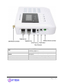
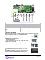
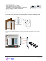
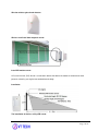
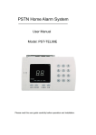
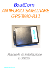
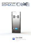
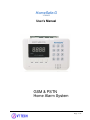
HomeSafe-G
VT-G992E
User’s Manual
GSM & PSTN
Home Alarm System
Page: 1 / 17
Table of Contents
1. Product Overview .........................................................................................................................3
2. Main Functions & Features ..............................................................................................................3
3. For Your Safety ............................................................................................................................4
4. VT-G992E Characteristics ...............................................................................................................4
5. Getting Started .............................................................................................................................5
5.1 Standard Package List ........................................................................................................5
5.2 View ................................................................................................................................5
5.3 Functional Parts ................................................................................................................6
5.4 Connecting and Installation ................................................................................................8
6. Operation Instructions: the factory password is: 0000 ............................................................................ 12
6.1 Keyboard setting:............................................................................................................ 12
6.1.1 Password: ................................................................................................................... 12
6.1.2 Siren alarm sound enable/disable: .................................................................................. 12
6.1.3 Set up alarm calling telephone numbers: ......................................................................... 12
6.1.4 Delete alarm calling telephone numbers: ......................................................................... 12
6.1.5 Siren alarm sound time out: ......................................................................................... 12
6.1.6 Alarming delay: ........................................................................................................... 12
6.1.7 ARMING delay:............................................................................................................ 12
6.1.8 Remote telephone ringing times: ................................................................................... 12
6.1.9 Siren sound feedback when using the remote control:....................................................... 13
6.1.10 Voice reminder function on/off and buzzer sound on/off: ................................................ 13
6.1.11 Alarm message recording: ........................................................................................... 13
6.1.12 Register and Delete remote controller/sensors: .............................................................. 13
6.1.13 Setting wired zones L1/L2: .......................................................................................... 13
6.1.14 Zone mode settings: ................................................................................................... 14
6.1.15 Alarm event history: ................................................................................................... 14
6.1.16 Telephone line tampering detection: .............................................................................. 14
6.1.17 Remote controller enable/disable: ................................................................................. 14
6.1.18 Remote control OUT power output: ............................................................................... 14
6.1.19 Setting up the system time and timing ARM/DISARM: ..................................................... 14
6.2 GSM messaging prompting: ............................................................................................. 15
6.2.1 Editing SMS prompting messages; ( 9 groups .................................................................. 15
6.2.2 Set the types of 6 groups alarming telephone number and power failure ............................. 15
6.2.3 Set the brightness adjustment of digital display ............................................................... 15
6.2.4 SMS commands: where 0000 is the password .................................................................. 15
7. Remote Controller (Key fob) Description ............................................................................................ 16
7.1. Set up Arm .................................................................................................................... 16
7.2 Set up Disarm................................................................................................................. 16
7.3. Emergency Alarm ........................................................................................................... 16
7.4. Intelligent Arm ............................................................................................................... 16
8. Alarm Panel LED Screen Indicator Status Description: ........................................................................... 16
9. Remote Control the system: ........................................................................................................... 17
10. Handing Incoming Alarm Phone Calls ............................................................................................. 17
11. Reset Factory Settings ................................................................................................................ 17
12. Copyright and Disclaimer ........................................................................................................ 17
Page: 2 / 17
1. Product Overview
VT-G992E is a GSM and PSTN intelligent home alarm system. This LED display alarm system is equipped
with dual network GSM & PSTN technologies and suitable for both home and commercial use. It uses
advanced GSM technology, GSM Wireless mobile and traditional PSTN landline networks with intelligent
alarm system. It has highly integrated digital voice, SMS, self-learning wireless communication code, and textmessaging technologies. The alarm provides automatic voice or SMS messaging as notification for incidents.
It is a choice of stability, reliability, security, and user-friendliness. Features are very practical, cost-effective,
and easy to use. This LED display alarm can integrate with many alarm accessories including door sensors,
smoke detectors, gas detectors, emergency buttons and other accessories to build a powerful security setup.
It has been widely used in homes, factories, schools, shops, convenience stores, financial and banking
workplaces, community centres and residential areas to provide protection to valuable assets.
2. Main Functions & Features
VT-G992E has the following main functions and features:
99 Wireless Zones and 2 wired zones with LED display
DC12V output(connect to wired sensors)
Support both GSM & PSTN telephone
English voice operation instruction
LED indicator Arm/Disarm/Stay arm/Alarm/Setting/Signal
Password protection function
5 groups of call phone number and SMS number, 1 group of emergency phone number and SMS
number
Programmable alarm delay: 0-99 seconds
Programmable alarm arming delay: 0-99 seconds
Programmable Siren sounding: 0-30 minutes
Zone name self-editing function
Programmable ring times
Timing arm and Timing disarm
Stay intelligent arm
Multi-Zones Triggered Mode (2 or more than 2 zones)
Repeat triggered alarm function (sensor alarm after triggered twice)
Doorbell
Anti-decoding protection function
Telephone line cutting detection
External power on and off SMS notification
Remote control via SMS and Phone
Remote control output for door open or light,…
Remote control to turn on and off Siren
Remote Monitoring/Arm/Disarm/Play records
Two way talking (External)
Page: 3 / 17
3. For Your Safety
Read these simple guidelines. Not following them may be dangerous or illegal.
Proper Connection
Qualified Accessories
Water Resistance
Confidential Phone Number
When connecting with other device, read carefully its manual so as to
carry out correct installation. Do not connect it to other incompatible
devices.
Use only original parts and peripheral equipments to avoid damage to
VT-G992E.
VT-G992E is not water resistant. Keep it dry. Install it inside the house
For safety reason, do not tell other people the mobile phone number of
your VT-G992E without taking precautions of security settings.
4. VT-G992E Characteristics
Items
Power Supply
Backup Battery
Frequency
Standby current
Alarm current
Wireless frequency
Support wireless sensors
Wireless distance
Record voice message
LED screen
Operating temperature
Humidity
Dimension
Weight
Specification
DC12V / 1A
Ni-Hi AAA*6 DC7.4V
GSM 900/1800/1900Mhz
55 mA
450 mA
433MHz
EV1527/300K 2262/1.5-4.7M
100m open
10s
display time/Arm/Disarm/Stay arm/Alarm/Setting
-10° to 50° C
5% to 95% Non-condensing
33*25*7.5cm
1.2KG
<
<
Page: 4 / 17
5. Getting Started
This section will describe how to set up your VT-G992E.
5.1 Standard Package List
VT-G992E is supplied in a box which includes:
5.2 View
Front View
Side View
Back View
Page: 5 / 17
5.3 Functional Parts
HomeSafe
LED screen display
F4
F5
F6
88:88
LED indicator
POWER
ALARM
TELEPHONE
MOBILE
Microphone
Function keyboard
ARMING
INTELLIGENT
DISARMING
ALARM
Speaker
Digital Keyboard
GSM is unavailable
Turn on GSM
Access GSM network
Minutes : Seconds
Power LED light, power supply working normal
Alarm LED light, alarm system alarm
Telephone LED light, telephone line work normal
Mobile LED flashes every 3 seconds, GSM network working
normal;
If the LED still light, access GSM network fail
Personal message record and remote monitoring
ARMING LED light, the alarm system into arm status
INTELLIGENT LED light, the alarm system into intelligent
status
DISARMING LED light, the alarm system into disarm
status
ALARM LED light, the alarm system into alarm status
English voice operation instruction
Setting alarm system function
Page: 6 / 17
GSM Antenna Connector
LINE1
LINE2
POWER
SIREN
ON OFF
Wireless Antenna Connector
Connect GSM antenna
Connect LINE1 to telephone uses telephone wire of
standard package list
Connect LINE2 to telephone out line
Connect DC12V adapter uses power adapter of standard
package list
Connect siren uses siren of standard package list
Power on battery or power off battery
Connect wireless antenna increase wireless distance
Page: 7 / 17
External Speaker
SP+
SPGND
Wired zones
L1
L2
OUT
12V
Connect speaker anode
Connect speaker negative
Connect wired zones COM port / Output DC12V negative
Wired zone 1, connect wired sensors NC or NO port
Wired zone 2, connect wired sensors NC or NO port
It is a can be programmed to control the output of the
DC12V
DC12V output, It can supply power for wired sensors
5.4 Connecting and Installation
Read this manual before using your VT-G992E and check if all parts are included in the packaging box.
4.4.1 Ensure that your VT-G992E has a 2G working SIM installed.
Before inserting SIM card, cut off the power for VT-G992E.
Install SIM Card
- Open the SIM card cover at the back of VT-G992E.
- Insert the SIM card by sliding it into the card slot with the chip
module facing to the connectors on PCB.
- Put back the SIM card cover.
- Check that the SIM has not run out of credit (test the SIM in a phone
to make sure it can call succeed)
- Check that the SIM Lock code is turned off
- If you require the function of sending an SMS to the mobile phone
number when it makes a alarming, please make sure the SIM card
have balance and the message function.
Check that the MOBILE LED is flashing 1 second on and 3 seconds
off.
If the MOBILE LED still light or the LED screen shows F4, please turn
off the power, check the SIM slot or GSM antenna and then turn on
again
Page: 8 / 17
4.4.2 Antenna Connection
Connect the GSM antenna to VT-G992E
Connect the Wireless antenna to VT-G992E.
- GSM antenna is used to receive GSM signals. It should not be
covered or shielded by any objects containing metal.
5.5 Sensor Installation:
Door sensor
The door/window magnetic sensor has two parts. The small part is the magnet to be mounted on the door and
the others, the sensor is to be mounted on the frame of the door. The sensor will activated will send the
wireless signal to controller immediately when the two.
In some circumstances the wired & wireless Infrared Fence detector is more appropriate than magnetic
sensors.
Page: 9 / 17
Wired or wireless glass break detector:
Wireless scroll steel door magnetic sensor:
Install PIR motion sensor:
A Passive Infra-red (PIR) Sensor is an electronic device that detects the motion or movement of some
person or animal by sensing the heat emitted from the body.
Installation:
The installation of wireless ceiling PIR sensor
Page: 10 / 17
Smoke/gas detectors:
a) Wired or wireless smoke detector
This smoke detector detects smoke by a couple of infrared diodes, which is suitable for detecting the smoke
in house, shop, hotel, restaurant, office building, school, bank, library and storehouse etc.
b) Wired or wireless gas detector
The product is ceiling mounted gas detector with high stability. It is used for detecting leaking gas and suitable
for the safety of residential house, villas, hotels, boarding house etc.
Detecting the gas heavier than air: installation height from floor: 0.3m ~ 1.0m, semi-diameter to gas sources:
< 1.5m; detecting the gas lighter than air: installation height from ceiling 0.3m ~ 1.0m, semi-diameter to gas
sources: < 1.5m.
Open or close
manipulator
/Test button
Power LED (green)
Working LED
Page: 11 / 17
Wired alarm zones
The alarm system have DC12V output, it can be used to supply the voltage for the wired sensors.
The alarm system support two wired zones L1/L2 are the 2 wire alarm inputs.
Note: The wired zone support NO/NC wired sensor.
6. Operation Instructions: the factory password is: 0000
6.1 Keyboard setting:
-
A long beep sound for all the proper operations
-
Two short sounds for wrong settings.
6.1.1 Password: Open/Close password protection function, Change user’s password
Command: *11*
Password protection enable
Command: *10*
Password protection disable
Command: *7xxxx* Password modification;
Ex: new password 8888 enter command *78888*
6.1.2 Siren alarm sound enable/disable:
Command: #00#
disable siren alarm sound
Command: #01#
enable siren alarm sound
A
6.1.3 Set up alarm calling telephone numbers:
Command: #NTTTTT#
Description:
A maximum of 6 numbers can be entered to the system:
-
N: value 1 to 6 (1 is the first input number and when there is an alarm condition the number is called
first)
TTTTT: is the phone number to be dialed (maximum 13), please enter it as you would make the
phone call dialing.
Ex: #18005558888# system will call this number 800555888 when there is an alarming condition.
6.1.4 Delete alarm calling telephone numbers:
Command: #N#:
Description:
N (1-6):
delete the entering telephone number.
6.1.5 Siren alarm sound time out:
Command #9xx#
Description: xx= 00-30 (minutes) ex: #95#, When alarming: the siren will sound 5 minutes.
6.1.6 Alarming delay:
Command: #7xx#
Description: xx= 00-99 (seconds) ex: #730#, the system will alarm after sensor is triggered 30 seconds.
6.1.7 ARMING delay:
Command: *4xx*
Description: xx= 00-99 (seconds) ex: *430*, the system will auto ARMING after press ARM key 30 seconds.
6.1.8 Remote telephone ringing times:
Command: *6x*
Description: x= 0-9 (seconds) ex: *63*, if will automatically get through after ringing 3 times,
*60*, means no ringing times.
Page: 12 / 17
6.1.9 Siren sound feedback when using the remote control:
Command: *21*
Description: The siren will have a short feedback sound when you press remote control
Command: *20*
Description: The siren feedback sound is off when you press remote control, only have buzzer sound.
6.1.10 Voice reminder function on/off and buzzer sound on/off:
Command: *041*
The voice reminder function: OFF
Command: *040*
The voice reminder function: ON
Command: *99*
The buzzer sound: OFF
Command: *98*
The buzzer sound: ON.
6.1.11 Alarm message recording:
Command: *0xxxx*
Description:
- xxxx = 4 numbers password
- You have 10 seconds to record your alarm message
- The system gives a long sound which means the record is successful.
- Using the telephone handset To hear the recording voice message, press *9* press any key to quit
6.1.12 Register and Delete remote controller/sensors:
Register Remote controller:
Command: *0*
Description: After pressing *0* on the alarm panel keyboard, then press any button of the remote controller
within 10 seconds. A long “Beep” sound means successfully.
Register Sensor:
Command: *01*
Description: After pressing *01* on the alarm panel keyboard, then trigger the sensor within 10 seconds. A
long “Beepi” sound means successfully.
Command: *03*
Description: Learning wireless keypad.
Assigning Zone Number;
Command: *8xx*
Description: xx = 00-99 zones number, ex: *816*, assign the register sensor to zone 16.
Delete all Remote Controllers
Command: *02*
Description: Delete all of the remote controllers
Delete all Sensors
Command: #8996#
Description: Delete all detectors.
6.1.13 Setting wired zones L1/L2:
Command: *061*
Enable wired zones
Command: *060*
Disable wired zones
Command: *91010*
Line 1 input:
NC
Command: *91011*
Line 1 input:
NO
Command: *91012*
Line 1 input:
State change
Command: *91020*
Line 2 input:
NC
Command: *91021*
Line 1 input:
NO
Command: *91022*
D Line 1 input: State change
Page: 13 / 17
6.1.14 Zone mode settings:
Command: #8xxA#
Description:
xx = 00-99 (zone number);
A= zone mode (0-7) 8 modes
0: Bypass mode:
The selected zone is disabled at all time
1: Common mode:
The selected zone is active when the system is arming
2: Intelligent mode:
The selected zone is disable when system INTELLIGENT ARMING
3. Emergency mode:
The selected zone is active at all time even the system is not arming
i.e; Smoke, Gas, Heat, Emergency panic sensors, …
4. Multi-Zones Triggered Mode: The selected zone is assigned to the Multi-Zones mode and
the alarm condition is triggered when 2 or more zones in this mode are active within 30
seconds.
5. Delay-alarm mode: When the selected zone is active the system will enter the delay
alarm mode.
6. Repeat triggered mode: when the detector in the selected zone is triggered once, the
system will not alarm immediately, only when it is triggered again within 30 seconds after
the first trigger, the system will alarm.
8. Doorbell mode:
The control panel will sound “ding dong” as the doorbell when the
selected zone is active.
6.1.15 Alarm event history:
Command: x
Description: x = (0-9) press key 0~9 to inquiry the latest 10 alarm events and display alarm defense area (0
means the most recent event).
6.1.16 Telephone line tampering detection:
Command: *51* Description: the system will alarm when telephone lines disconnect or failure
Command: *50* Description: the system will not detect telephone lines disconnection or fault.
6.1.17 Remote controller enable/disable:
Command: *31* Description: Remote controller is disabled.
Command: *30* Description: Remote controller is enabled
6.1.18 Remote control output OUT:
Command: #80A#
Description: A = 0-9
0: OUT line out is disabled
1: OUT line out is only active in the DISARMING mode
2: OUT line out is only active in the Intelligent ARMING mode and during the alarming period.
3: OUT line out is only active in the Intelligent ARMING mode and is disable during the alarming period.
4: OUT line out is only active in the ARMING mode and during the alarming period.
5: OUT line out is only active in the ARMING mode and is disable during the alarming period
6: OUT line out is only active in any ARMING condition mode and during the alarming period.
7: OUT line out is only active in any ARMING condition mode and is disable during the alarming period
8: OUT line out is active in the alarm mode
9: OUT line out is active
6.1.19 Setting up the system time and timing ARM/DISARM:
Command: *07HHMM*
System time setting
Description: HH = hour (0-23) , MM= minute (0-59); Ex: *071830*, means set up the time to be 18:30
Command: #07HHMMA#
Alarm arming timer
Description HH = hour (0-23) , MM= minute (0-59); Ex: *071830*, means set up 18:30
A = 0-9: 9 group of alarm timing can be programmed: 0 = disable arming timer; group 1 to group 5 timer can
be used repeatedly, group 6 to group 9 timer can be used only one time; Ex: #0700000# all timer off.
Page: 14 / 17
Command: #08HHMMA#
Alarm disarming timer
Description HH = hour (0-23) , MM= minute (0-59); Ex: *071830*, means set up 18:30
A = 0-9: 9 group of alarm timing can be programmed: 0 = disable arming timer; group 1 to group 5 timer can
be used repeatedly, group 6 to group 9 timer can be used only one time; Ex: #0800000# all timer off.
Command: #09HHMMA#
Description: “HH” means hour(2-degits), “MM” means Minute(2-degites), the hour is 24 clock.
“A” 0-9 : Can set 9 groups timing time strike: 0 = disable timing time strike; group 1 to group 5 timing strike
can be used repeatedly, group 6 to group 9 timing strike can be used only one time;
Ex: #0900000# close all timing arm
( )
6.2 GSM messaging prompting:
6.2.1 Editing SMS prompting messages; ( 9 groups)
SMS: 0000AB
Description: Editing sms, 0000 is password, “A” (1-9), means 1-9 group numbers; “B” means SMS
content(e.g. this is a door sensor alarm)
e.g. send sms:” 00001 this is a door sensor alarm” this is the first group self editing sms.
SMS: 0000A*
Description: Query the editing sms contents, 0000 is password, “A” (1-9), means 1-9 group numbers; e.g.
send sms: 00001*, the system will reply the first group sms contents.
Command: #03AAB#
Description: sms direction after alarming, “AA” zone number (00-99), “B” is 9 group editing sms contents(0-9).
EX #03011#, the system will send the first group SMS contents to user after zone 1 be triggered.
6.2.2 Set the types of 6 groups alarming telephone number and power failure
Command: #AB#
Description: Set the types of 6 groups alarming telephone number, A=1-6 means 1-6 groups alarming
telephone number; B=2-4 , 2 means only give a call to user when the system alarming, 3 means only give a
SMS to user when the system alarming, 4 means give call and SMS to user when the system alarming.
st
e.g. #14# means the 1 group telephone number can send SMS and make a call;
st
#12# means the 1 group telephone number only can make a call, cannot send SMS;
Command: *05A*
Description: Set power failure alert A = 0-7 0 means close power failure alert function 1-6 means send
to which group telephone number when power failure. 7 means send power failure alert SMS to all 6 group
telephone numbers.
,
,
,
6.2.3 Set the brightness adjustment of digital display
Command: *08A*
Description: A(0-7), 8 level brightness adjustment.
6.2.4 SMS commands: where 0000 is the password
SMS: 0000CF
Disarm the system
SMS: 0000SF
Arm the system
SMS: 0000bF
Intelligent arm the system
SMS: 0000STATUS
Querying status of the system
SMS: 0000ON
Set the OUT line active
SMS: 0000OFF
Disable the OUT line
Note: All the above mentioned commands can be operated by editing text message with the format of
“password + the content of command”. For example If setup the first phone number as 87654321 by SMS,
edit “0000#187654321# ”and send it to the alarm panel;
Page: 15 / 17
7. Remote Controller (Key fob) Description
7.1. Set up Arm
Press “ ”button on the remote controller, and the LED display “SF”, means system “Armed”.
7.2 Set up Disarm
Press “ ” button on the remote controller, and the LED display “CF”, means system “Disarmed”.
7.3. Emergency Alarm
Press “ ”button on the remote controller for emergency help, And the LED display “99”.
Press“ ”button on the remote controller one time is silent alarm, while press “ ”button twice or long time the
siren will sound.
7.4. Intelligent Arm
Press “” button on the remote controller and the LED display “bF”, means system “Intelligent Armed”.
8. Alarm Panel LED Screen Indicator Status Description:
LED Indicator Display
Status Description
SF
Arm
CF
Disarm
99
Emergency Alarm
bF
Intelligent Arm
F1
Telephone Line Disconnect Alarm
F3
No Registered Sensors
F4
GSM is unavailable
F5
Turn on GSM
F6
Access GSM network
1-98
Wireless Defense Zones
L1-L2
Wired Defense Zones
Page: 16 / 17
9. Remote Control the system:
You can use any telephone to dial the numbers of the system and it will put on automatically get through after
system detecting the ring times you have been setup. When you hear the beep, input passwords (two beep
sounds if the password is wrong, if the password input wrongly 3 times or no any operations within 20
seconds the phone will hang up automatically) and if it is correct, you can have remote control of the system,
press # after accomplishing all operations, then you can implement other operations and hang up telephone.
Press “1” to monitor (Press “1” again for monitor 20 seconds more.)
Press “2” to start the siren
Press “3” to stop the siren
Press “4” to arm
Press “5” to disarm
Press “6” to play the recorded personal voice message
Press “7” to open 12V output
Press “8” to close 12V output
Press “9” to close the speaker (External)
Press “0” to open the speaker (External)
Press “#” to affirm and hang up
10. Handing Incoming Alarm Phone Calls
When sensors are triggered or emergency help, the alarm panel will dial up the setup telephone numbers
automatically and give alarm rings based on settings. If the host’s phone is in use or not able to connect, the
system will dial next alarm phone, until it is dialed and hosts confirm. It will play records after receiving alarm
phone and the operation methods are similar to remote setup.
11. Reset Factory Settings
Command:*80000*
Description: 0000 is default password (All settings will be cleared except all the registered sensors)
12. Copyright and Disclaimer
Copyright © 2014VT TECH Corp. All rights reserved.
The user manual may be changed without prior notification.
This user manual, or any part thereof, may not be reproduced for any purpose whatsoever without the written
authorization of VT TECH Corp., or transmitted in any form, either electronically or mechanically, including
photocopying and recording.
In no event shall VT TECH Corp be liable for direct, indirect, special, incidental, or consequential damages
(including but not limited to economic loss, personal injury, and loss of asset and property) arising out of the
use or inability or illegality to use the product or documentation.
If you encounter any problems when using our products, and cannot solve them by yourself, please contact
our technical support team by writing an E-Mail to [email protected].
Page: 17 / 17