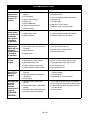
1
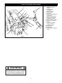
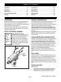
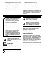
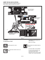
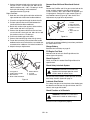
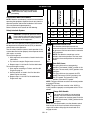
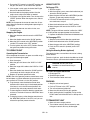
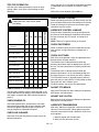
Professional 2-Wheel Tractor
Owner/Operator Manual
Models
985114 - 16 HP
985115 - 8.5 HP
985117 - 13.5 HP
985119 - 12 HP
08499300 1/03
Printed in USA
CONTROLS AND FEATURES
7
2
1
3
4
15
5
6
8
10
9
11
12
1
14
1
13
OH0160
Figure 1
WARNING
The engine exhaust from this product
contains chemicals known to the State
of California to cause cancer, birth
defects or other reproductive harm.
OL4030
2
ENGLISH
1. Operator Presence
Control
2. Steering Brake
Handlebar
3. Throttle Control
4. Ignition Switch
5. Hourmeter
6. Range Shift Handle (Two
Speed Axle)
7. Direction Control Lever
8. Parking Brake Handle
(Optional on 8.5HP)
9. Brake Handle Cross Bar
10. Choke Lever (Robin &
Kohler)
11. Choke Control Knob
(Briggs & Stratton)
12. Instruction Plate
13. Kick Stand
14. PTO Control
15. Gear Shift Lever (Hi/Low
Gear)
TABLE OF CONTENTS
Safety . . . . . . . . . . . . . . . . . . . . . . . . . . . . . . . . . . . 4
Troubleshooting . . . . . . . . . . . . . . . . . . . . . . . . . 20
Assembly . . . . . . . . . . . . . . . . . . . . . . . . . . . . . . . . 8
Accessories . . . . . . . . . . . . . . . . . . . . . . . . . . . . 21
Operation . . . . . . . . . . . . . . . . . . . . . . . . . . . . . . . 11
Attachments . . . . . . . . . . . . . . . . . . . . . . . . . . . . 21
Maintenance. . . . . . . . . . . . . . . . . . . . . . . . . . . . . 14
Service Parts . . . . . . . . . . . . . . . . . . . . . . . . . . . 22
Service and Adjustments . . . . . . . . . . . . . . . . . . 16
Specifications. . . . . . . . . . . . . . . . . . . . . . . . . . . 22
Storage . . . . . . . . . . . . . . . . . . . . . . . . . . . . . . . . . 19
Warranty . . . . . . . . . . . . . . . . . . . . . . . . . . . . . . . 23
INTRODUCTION
THE MANUAL
PRODUCT REGISTRATION
Before operation of unit, carefully and completely read
your manuals. The contents will provide you with an
understanding of safety instructions and controls during
normal operation and maintenance.
All reference to left, right, front, or rear are given from
operator standing in operation position and facing the
direction of forward travel.
The Gravely dealer must register the product at the time
of purchase. Registering the product will help the
company process warranty claims or contact you with the
latest service information. All claims meeting
requirements during the limited warranty period will be
honored, whether or not the product registration card is
returned. Keep a proof of purchase if you do not register
your unit.
Customer Note: If Dealer does not register your product,
please fill out, sign and return the product registration
card to Gravely.
MODEL AND SERIAL NUMBERS
Transfer
model &
serial
number
label from
product
registration
here.
When ordering publications,
replacement parts, or making service
inquiries, know the Model and Serial
numbers of your unit and engine.
Numbers are located on the product
registration form in the unit literature
package. They are printed on a serial
number label, located on the frame of
your unit (Figure 2).
Serial
Number
Label
UNAUTHORIZED REPLACEMENT PARTS
Use only Gravely replacement parts. The replacement of
any part on this equipment with anything other than a
Gravely authorized replacement part may adversely
affect the performance, durability, and safety of this unit
and may void the warranty. Gravely disclaims liability for
any claims or damages, whether regarding warranty,
property damage, personal injury or death arising out of
the use of unauthorized replacement parts.
NOTE: To locate your nearest Gravely Dealer, call
1-800-472-8359 or go to www.gravely.com on the internet.
DISCLAIMER
Gravely reserves the right to discontinue, change, and
improve its products at any time without public notice or
obligation to the purchaser. The descriptions and
specifications contained in this manual were in effect at
printing. Equipment described within this manual may be
optional. Some illustrations may not be applicable to your
unit.
DEALER DELIVERY
Figure 2
Dealer should:
1. Test brakes after tractor is assembled to be sure
adjustment has not been disturbed in shipment.
Wheel brakes are properly adjusted at factory.
Copyright 2003 Ariens Company
GB - 3
2. Check the safety interlock system to make sure that
it is functioning properly. Unit must not start unless
direction control lever is in neutral (N) and Power
Takeoff (PTO) is disengaged (Off). Engine must
stop if operator releases the handlebar with the
direction control lever or PTO engaged (On). See
Safety Interlock System on page 11.
3. Fill out Original Purchaser Registration Card and
return the card to Gravely.
4. Explain Gravely Limited Warranty Policy.
5. Explain recommended lubrication and
maintenance. Advise customer on adjustments.
Instruct customer on controls and operation of unit.
Discuss and emphasize the Safety Precautions.
Give customer Owner/Operator, Parts, and Engine
Manuals. Advise customer to thoroughly read and
understand them.
Customer Note: Your Dealer has been provided
complete setup and preparation instructions which must
be completed prior to you taking delivery of this unit. The
dealer is required to review important information in this
manual with you before or upon delivery of the unit or
attachment.
SAFETY
WARNING: This cutting machine is capable
of amputating hands and feet and throwing
objects. Failure to observe the safety
instructions in the manuals and on decals
could result in serious injury or death.
Slopes are a major factor related to
loss-of-control and tip-over accidents.
Operation on all slopes requires extra
caution.
Tragic accidents can occur if the operator is
not alert to the presence of children. Never
assume that children will remain where you
last saw them.
Gasoline is extremely flammable and the
vapors are explosive, handle with care.
Disengage attachment, stop unit and engine,
remove key, engage parking brake, and allow
moving parts to stop before leaving operator’s
position.
SAFETY ALERTS
Look for these symbols to point out
important safety precautions. They mean:
WARNING: POTENTIALLY HAZARDOUS
SITUATION! If not avoided, COULD
RESULT in death or serious injury.
CAUTION: POTENTIALLY HAZARDOUS
SITUATION! If not avoided, MAY RESULT in
minor or moderate injury. It may also be
used to alert against unsafe practices.
NOTATIONS
NOTE: General reference information for proper
operation and maintenance practices.
IMPORTANT: Specific procedures or information
required to prevent damage to unit or attachment.
PRACTICES AND LAWS
Practice usual and customary safe working precautions,
for the benefit of yourself and others. Understand and
follow all safety messages. Be alert to unsafe conditions
and the possibility of minor, moderate, or serious injury or
death. Learn applicable rules and laws in your area,
including those that may restrict the age of the operator.
Attention!
REQUIRED OPERATOR TRAINING
Personal Safety Is Involved!
Original purchaser of this unit was instructed by the seller
on safe and proper operation. If unit is to be used by
someone other than original purchaser; loaned, rented or
sold, ALWAYS provide this manual and any needed
safety training before operation.
Become Alert!
Obey The Message!
The safety alert symbols above and signal words below
are used on decals and in this manual.
Read and understand all safety messages.
DANGER: IMMINENTLY HAZARDOUS
SITUATION! If not avoided, WILL RESULT in
death or serious injury.
GB - 4
SAFETY DECALS AND LOCATIONS
ALWAYS replace missing or damaged Safety Decals.
Refer to Figure 3 below for Safety Decal locations.
THROTTLE
2
MADE IN U.S.A.
FAST
!
SAFETY FIRST
R E A D T H E O P E R AT O R ' S M A N U A L S B E F O R E O P E R AT I N G
O R S E R V I C I N G T H I S E Q U I P M E N T.
DISENGAGE PTO AND SHIFT INTO NEUTRAL BEFORE
S TA R T I N G E N G I N E .
N E V E R A L L O W C H I L D R E N TO O P E R AT E T H E E Q U I P M E N T.
K E E P H A N D S A N D F E E T AWAY F R O M M O V I N G PA R T S .
S TAY A L E R T F O R P E R S O N S A N D H A Z A R D S .
B E F O R E L E AV I N G O P E R AT O R ' S P O S I T I O N :
– PUT PTO CONTROL IN THE OUT POSITION.
– R E M O V E I G N I T I O N K E Y.
– ENGAGE FWD – REV AND HI – LO CONTROLS.
PUSH OFF
PTO
Units with Briggs &
Stratton Engines
IGNITION
SLOW
HIGH-PUSH
CHOKE
RANGE
PULL ON
PUSH OFF
LOW-PULL
PULL ON
1
N
Units with Kohler &
Robin Engines
DA N G E R
TO AVOID SERIOUS INJURY OR DEATH
• Read the operator's manual.
• Do not mow when children or others are
around.
• Look down and behind before and while
backing.
• Never carry children.
• Remove objects that could be thrown by
the blade.
• Go across slopes, not up and down.
• If machine stops going uphill, stop blade and
back down slowly.
• Avoid sudden turns.
• Keep safety devices (guards, shields, switches,
etc.)in place and working.
• Check interlock system per manual before use.
• Understand location and function of all controls.
• When parking on a slope always chock or block
the wheels.
H
L
077478
DANGER
4
!
CAUTION
DO NOT PARK ON SLOPE UNLESS WHEELS ARE CHOCKED.
Units with Briggs &
Stratton Engines
3
SAFETY FIRST
READ THE OPERATOR'S MANUAL
BEFORE USING TRACTOR
DISENGAGE ALL CLUTCHES AND
SHIFT INTO NEUTRAL BEFORE
STARTING ENGINE
HANDLE
KEEP
GASOLINE WITH CARE
SHIELDS, GUARDS AND SAFETY
KEEP
DEVICES IN PLACE
HANDS AND FEET AWAY FROM
NEVER LET
MOVING PARTS
CHILDREN OPERATE TRACTOR
BE ALERT FOR DANGER TO BYSTANDERS, PROPERTY AND FOR
TERRAIN HAZARDS
REMOVE
IGNITION KEY BEFORE LEAVING
TRACTOR
ENGAGE FWD - REV
CONTROL AND HI - LO GEAR
CONTROLS WHEN PARKING
•
•
•
••
•
BRAKE
P
LOCK
•
•
RELEASE
077247
Units with Steering Brakes
Figure 3
1. DANGER!
• Look down and behind before and
while backing.
To Avoid Injury or Death
• Never carry children.
Read the operator’s manual.
Remove objects that could be thrown by
the blade.
• Go across slopes, not up and down.
Do not mow when children or others are
around.
• If machine stops going uphill, stop
blade and back down slowly.
• Keep safety devices (guards, shields,
switches, etc.) in place and working.
GB - 5
• Check interlock system per manual
before use.
• Understand location and function of all
controls.
• When parking on a slope always
chock or block the wheels.
2. SAFETY FIRST
•
Read the operator’s manuals before operating or
servicing this equipment.
•
Disengage the PTO and shift into neutral before
starting engine.
•
Never allow children to operate the equipment.
•
Keep hands and feet away from moving parts.
•
Stay alert for persons and hazards.
•
Before leaving operator’s position:
- Put PTO control in the out position.
- Remove ignition key.
- Engage FWD-REV and Hi-Lo controls.
3. SAFETY FIRST
•
Read the operator’s manuals before using
tractor.
•
Disengage all clutches and shift into neutral
before starting engine.
•
Handle gasoline with care.
•
Keep shields, guards and safety devices in place.
•
Keep hands and feet away from moving parts.
•
Never let children operate tractor.
•
Be alert for danger to bystanders, property and
for terrain hazards.
•
Remove ignition key before leaving tractor.
•
Engage FWD-REV control and Hi-Lo gear
controls when parking.
4. CAUTION!
Do not park on a slope unless wheels are chocked.
SAFETY RULES
Read, understand and follow all safety practices in
Owner/Operator Manual before beginning assembly.
Failure to follow instructions could result in personal
injury and/or damage to unit.
ALWAYS remove key (if equipped) and disconnect wire
from spark plug before assembly. Unintentional engine
start up can cause death or serious injury.
Complete a walk around inspection of unit and work area
to understand:
• Work area
• Your unit
• All safety decals
ALWAYS check overhead and side clearances carefully
before operation.
ALWAYS be aware of traffic when operating along streets
or curbs.
Keep children and people away.
Keep children out of work area and under watchful care
of a responsible adult.
Keep area of operation clear of all toys, pets, and debris.
Thrown objects can cause injury.
Check for weak spots on docks, ramps or floors. Avoid
uneven work areas and rough terrain.
Avoid slippery surfaces. ALWAYS be sure of your footing.
DO NOT operate on wet grass.
Dust, smoke, fog, etc. can reduce vision and cause an
accident. Operate unit only when there is good visibility
and light.
Read the entire Owner/Operator manual and other
training material. If the operator or the mechanic cannot
read the manual, it is the owner’s responsibility to explain
it to them. Only the user can prevent and is responsible
for accidents or injuries occurring to themselves, other
people or property.
• Only trained adults may operate or service unit
• Training includes actual operation
NEVER allow children to operate or play on or near unit.
Be alert and shut off unit if children enter area.
Never carry passengers.
NEVER operate unit after or during the use of
medication, drugs or alcohol. Safe operation requires
your complete and unimpaired attention at all times.
NEVER allow anyone to operate this unit when their
alertness or coordination is impaired.
Wear adequate safety gear, protective gloves and
footwear.
NEVER wear open sandals or canvas shoes during
operation.
Protect eyes, face and head from objects that may be
thrown from unit. Wear appropriate hearing protection.
Sharp edges can cut. Moving parts can cut off fingers or
a hand. Wrap blade(s), wear sturdy gloves and use
extreme caution when servicing. On multi-blade mowers,
rotation of one blade will cause all blades to rotate.
ALWAYS keep hands and feet away from all rotating
parts during operation. Rotating parts can cut off body
parts.
ALWAYS keep hands away from all pinch points.
GB - 6
DO NOT touch unit parts which might be hot from
operation. Allow parts to cool before attempting to
maintain, adjust or service.
NEVER place your hands or any part of your body or
clothing inside or near any moving part while unit is
running.
DO NOT wear loose clothing or jewelry. Tie back hair that
may get caught in rotating parts.
Keep children and people away from unit during
operation.
Fumes from engine exhaust can cause injury or death.
DO NOT run engine in an enclosed area. Always provide
good ventilation.
Thrown objects can cause injury and property damage.
DO NOT point discharge at anyone or discharge directly
onto paved or gravel surfaces.
Always stand clear of the discharge area when operating
this unit.
Read, understand, and follow all instructions in the
manual and on the machine before starting.
Understand:
• How to operate all controls
• The functions of all controls
• How to STOP in an Emergency
• Braking and steering characteristics
• Turning radius and clearance
ALWAYS keep protective structures, guards, and panels
in good repair, in place and securely fastened.
NEVER modify or remove safety devices.
ALWAYS keep discharge cover or complete grass
catcher in place and in proper working condition.
Check steering control operation frequently. Adjust and
service as required.
Safety Interlock System must function properly. DO NOT
operate unit if operator presence control is damaged or
disabled.
If equipment vibrates abnormally, stop engine at once,
disengage PTO, wait for all moving parts to stop, and
remove key. Check for any damage or loose parts. Repair
before restart.
Before starting engine: disengage PTO and place unit in
neutral.
DO NOT operate at too fast a rate. DO NOT change
engine governor settings or over-speed engine. Slow
down and turn corners slowly.
Disengage PTO when attachment is not in use. ALWAYS
turn off power to attachment when travelling, crossing
driveways, etc.
Avoid uneven and rough terrain. DO NOT operate near
drop offs, ditches, or embankments. Unit can suddenly
turn over if a wheel is over the edge of a cliff or ditch, or if
an edge caves in.
DO NOT try to stabilize unit by putting foot on ground
when operating with applicable riding attachments.
When engine is running and speed control lever is
forward, holding only one steering lever will cause unit to
circle around one drive wheel.
Use care when approaching blind corners, shrubs, trees
or other objects that may obscure view.
ALWAYS disengage PTO, stop unit and engine, remove
key and allow moving parts to stop before leaving
operator’s position.
Never leave a running unit unattended. ALWAYS shut off
engine before leaving unit.
ALWAYS remove key to prevent unauthorized use.
DO NOT operate in reverse unless absolutely necessary.
ALWAYS backup slowly. ALWAYS look down and behind,
before and while backing.
DO NOT operate on steep slopes. DO NOT operate on
slopes of more than 10°. Operate across the face of
slopes, not up and down.
Turf conditions can affect the unit’s stability.
Keep all movement on slopes slow and gradual. DO NOT
make sudden changes in speed or direction. Use a slow
speed to avoid stopping or shifting on slopes. Avoid
starting or stopping on a slope.
DO NOT park unit on a slope unless absolutely
necessary. When parking on a slope always chock or
block wheels.
Use extra care when loading or unloading unit onto trailer
or truck.
Secure unit chassis to transport vehicle. NEVER secure
from rods or linkages that could be damaged.
DO NOT transport machine while engine is running.
Keep unit free of grass, leaves, or other debris. Clean up
oil or fuel spills.
This product is equipped with an internal combustion
engine. DO NOT use on or near any unimproved, forest
covered or brush covered land unless the exhaust
system is equipped with a spark arrester meeting
applicable local, state or federal laws. A spark arrester, if
used, must be maintained in effective working order by
the operator.
Fuel is highly flammable and its vapors are explosive.
Handle with care. Use an approved fuel container.
No smoking, No sparks, No flames. ALWAYS allow
engine to cool before servicing.
NEVER fill fuel tank when engine is running or hot from
operation.
NEVER fill or drain fuel tank indoors.
Replace fuel cap securely and clean up spilled fuel.
Never fill containers inside a vehicle or on a truck or
trailer bed with a plastic liner. Always place containers on
the ground away from your vehicle before filling.
When practical, remove gas-powered equipment from
the truck or trailer and refuel it on the ground. If this is not
possible, then refuel such equipment on a trailer with a
portable container, rather than from a gasoline dispenser
nozzle.
GB - 7
Keep the nozzle in contact with the rim of the fuel tank or
container opening at all times until fueling is complete.
Do not use a nozzle lock-open device.
If fuel is spilled on clothing, change clothing immediately.
Battery posts, terminals and related accessories contain
lead and lead compounds, chemicals known to the State
of California to cause cancer and reproductive harm.
Wash hands after handling.
Reverse connections may cause sparks which may result
in injury. ALWAYS connect/disconnect cables in proper
order.
Poisonous battery fluid contains sulfuric acid and its
contact with skin, eyes, or clothing can cause severe
burns.
Explosive Gases! No flames, No sparks, No smoking
near battery.
ALWAYS wear safety glasses and protective gear near
battery.
DO NOT TIP battery beyond a 45° angle in any direction.
ALWAYS keep batteries out of reach of children.
Before making any inspections, repairs, etc.: disengage
PTO, stop unit and engine, remove key, allow moving
parts to stop.
Allow hot parts to cool.
ALWAYS block wheels, engage parking brake and know
all jack stands are strong, secure and will hold weight of
unit during maintenance.
An extension spring, when extended, stores energy and
can be dangerous. Always use tools specifically designed
for installing or removing an extension spring. Always
compress or extend springs slowly.
ALWAYS maintain unit in safe operating condition.
Damaged or worn out muffler can cause fire or explosion.
Keep hardware, especially blade attachment bolts, tight.
Maintain or replace safety and instruction labels, as
necessary.
For unit storage or extended storage:
• NEVER store with fuel in fuel tank, inside a building
where any ignition sources are present.
• Allow engine to cool completely.
Use only attachments or accessories designed for your
unit.
Check attachment components frequently. If worn or
damaged, replace with manufacturer’s recommended
parts.
Use extra care with grass catchers and other
attachments. These can change the stability of the unit.
Use only approved hitch points.
ALWAYS be aware of attachments when turning.
ALWAYS allow adequate clearance between
attachments, personnel, and other objects.
ASSEMBLY
Fwd-Rev
Control
Rod
WARNING: AVOID INJURY. Read and
understand entire Safety section before
proceeding.
Hi-Lo
Control Rod
TOOLS REQUIRED
Phillips Screwdriver, Needle Nose Pliers, Open-End
Wrench: 3/8, 7/16, 9/16 & 3/4 and/or Adjustable Wrench
Handlebar
Assembly
REMOVE UNIT FROM CARTON
Remove the unit and components from the shipping
container.
Tractor
Assembly
Optional
Brake Handle
Assembly
Brake Rod, RH
Brake Rod, LH
Figure 4
GB - 8
DH0010
ASSEMBLY
4. Retain the handlebar in position with four
3/8-16 x 1 1/4 bolts and locknuts and tighten
hardware (Figure 6).
5. Connect the wiring harness from handlebar to the
unit.
6. Mount the Hi-Lo gear control handle assembly and
pivot to the left handlebar with a 1/2-13 x 3 1/2 bolt,
locknut, and washer (Figure 7).
Install Hubs and Wheels
For Semi-Pneumatic Wheels: install bushings and
wheel/hub assemblies onto tractor axles. For all other
wheels: install hubs to axles and secure wheels to hubs
with hardware provided.
Install Kick Stand
Slide kick stand into the righthand side of the lower
bracket on the rear hitch. Secure it in position with the
adjusting handle. The hair pin holds kick stand in the
raised position.
2
1
8
7
2
3
6
1
5
4
5
3
DH0040
5
4
1. Adjusting Handle
2. Lower Bracket
3. Rear Hitch
1. Hi-Lo Control Handle
Assembly
2. Brake Handle Grip
3. Left Handlebar
4. 1/2-13 x 3 1/2 Hex Bolt
4. Hair Pin
5. Kick Stand
Figure 5
5.
6.
7.
8.
Adjust and Jam Nuts
Extension Rod
Hi-Lo Control Rod
Pivot
Figure 7
DH0080
Assemble Steering Brakes (Optional)
Position Handlebar
4
2
3
2
5
3
4
1
4
7
3
8
1
9
6
1. Ignition Switch
Harness
2. Ignition Switch
5
3. Instrument Panel
4. Control Lever
5. Handlebar (Left)
Figure 6
1. Steering Brake
Handle
2. Instruction Plate
3. Left Hand Brake Rod
4. Right Hand Brake
Rod
5. Rear Hitch
DH0020
IMPORTANT: DO NOT damage ignition harness and
wires when positioning handlebar.
1. Position the handlebar right side up.
2. Move the left handle of the handlebar under the
right side of the frame, across the engine and out
between the left side of the frame and the PTO
control.
3. Rotate the handlebar into the mounting position.
6. Adjustment Bracket
7. Bolt and Nut (remove
first)
8. Right Hand Brake
Assembly
9. Brake Handle
Weldment
Figure 8
1. Remove nut and bolt from brake handle brackets
(Figure 8).
Left Hand Rod:
1. Hook the rear of the left hand brake rod into the left
side of the brake handle weldment.
NOTE: Before installing on rear hitch, place the forward
end of the left hand brake rod below muffler brace.
GB - 9
2. Connect the forward end to the pivot plate on the
unit with a .375 x .75 clevis pin, two .406 x .812 x
.065 flat washers and a .09 x .75 cotter pin. Insert
clevis pin with cotter pin to the outside of
adjustment bracket (Figure 8).
Right Hand Rod:
1. Hook the rear of the right hand brake rod into the
right outside end of the brake handle weldment.
2. Place the carriage bolt through the brake handle.
3. Put two nylon washers on the bolt between the
handle and the handlebar weldment.
4. Retain with another nylon washer, rubber washer,
steel washer and lock nut (Figure 9).
5. Connect the adjustment bracket to the cam lever
arm on unit with a clevis pin, two .406 x .812 x .065
flat washers and .09 x .75 cotter pin.
6. Push brake handle grip onto handle.
7. Connect the interlock plug to the wiring harness.
8. Fasten the instruction plate and the brake handle
weldment to the rear hitch with the nut and bolt just
removed and an additional 1/2-13 bolt and locknut.
9. Adjust brakes per Adjustments.
Connect Gear Shift and Directional Control
Rods
Connect the Fwd/Rev and Hi-Lo gear control rods to the
tractor and their respective handles using bushings,
1/4-20 x 1.5 bolts, .281 x .625 x .065 x flat washers and
1/4-20 locknuts. See the Hi-Lo gear control (Figure 7)
and Fwd/Rev control (Figure 10). See Service and
Adjustments on page 16 for adjustments.
1
5
4
3
2
1. Fwd/Rev Control
Handle
2. Right Handlebar
3. Hand Lever Pivot
4. Fwd/Rev Control
Rod
5. Adjust and Jam
Nuts
Figure 10
Install Attachment(s)
Install each attachment following instructions provided in
the attachment manual.
Charge Battery
See See Service Battery on page 15.
2
1
3
4
Fill Engine Fuel Tank
3
5
Add clean fuel to fuel tank. See Engine Manual for
correct type and capacity.
Check Engine Oil
Check and add oil if needed. See Engine Manual for
specifications.
7
Check Safety Interlock System
6
1.
2.
3.
4.
Carriage Bolt
Parking Brake Handle
Nylon Washer
Brake Handle Weldment
WARNING: FAILURE OF INTERLOCK,
together with improper operation could
result in death or serious injury.
5. Rubber Washer
6. Lock Nut
7. Steel Washer
Figure 9
Be sure that safety interlock system operates correctly.
See Safety Interlock System on page 11.
Lubricate Pivot Points
Put a drop of engine oil on the pivots of the throttle lever,
the direction control lever, the gear shift lever, the PTO
control, and range shift handle.
Check Function of all Controls
WARNING: FAILURE OF CONTROLS
could result in death or serious injury.
Ensure unit runs and performs properly.
GB - 10
DIRECTION CONTROL
LOCKED FORWARD
KEY
OPERATOR PRESENCE
CONTROL
ENGINE
OPERATION
A
Off
Yes
On
Off
Won’t
Crank
B
On
No
On
Off
Won’t
Crank
C
Off
Yes
On
On
Won’t
Crank
WARNING: AVOID INJURY. Read and
understand entire Safety section before
proceeding.
TEST
NOTE: Read the attachment(s) and unit manuals before
operating the equipment. Operate the unit only from the
operator’s position, behind the handlebars. Service the
unit and attachment before operating.
Refer to Controls and Features for the following.
With Engine Off
Safety Interlock System
CAUTION: The operator presence control
helps protect the operator from the moving
parts of the attachment and the powered
movement of the equipment.
NOTE: One of the operator presence control levers must
be depressed so the power take off (PTO) or direction
control lever can be operated.
Test the safety interlock system at each operation. If the
system does not function properly, do not operate the unit
until repairs are made.
To test with engine off:
1. With engine off, set controls as listed in line A of the
table below.
2. Try to start the engine. Engine must not crank.
3. Repeat steps 1-2 for lines B-C of the table below.
To test with engine running:
1. Start engine according to To Start and Shut Off
Engine on page 12.
2. Set the controls as listed in line D of the table
below. Engine must stop.
3. Repeat steps 1-2 for line E of the table below.
Engine must stop.
PTO
CONTROLS AND FEATURES
With Engine On
D
Off
Yes
On
Off
Stops
E
No
On
Off
Stops
FWD
N
REV
HIGH
On
Direction Control Lever
The direction control lever controls the
movement of the unit. Push the control forward
to go forward. Pull the control back to move the
unit backwards.
NOTE: The direction control lever can be
locked in the forward position. The lever must
be held in the reverse position to travel backwards.
Gear Shift Lever
The gear shift lever has two operating
positions. The forward (“HIGH”) position is the
fast gear. The rearward (“LOW”) position is the
GEAR
slow gear.
SHIFT
The gear shift lever also controls the PTO
speed. The forward (“HIGH”) position is the
LOW
fast PTO speed. The rearward (“LOW”)
position is the slow PTO speed.
NOTE: The gear shift lever must be in the neutral position
to engage PTO lever.
NOTE: The gear shift lever must be in the “HIGH” or
“LOW” position to properly transmit power to the PTO or
wheels.
Range Shift Handle
The range shift handle has two operating
positions. Pull the handle to the rearward
H
(“LOW”) position for the slow speed. Push the
L handle to the forward (“HIGH”) position for the
fast speed.
NOTE: On two-speed models, use the direction control
lever to rock the unit back and forth while moving the
range shift handle to help align the clutch teeth and
engage the axle.
GB - 11
FILL FUEL TANK
WARNING: Never move the range shift
handle while on a slope or while the tractor
is moving. Move the handle only when the
tractor is on level ground and stopped
(except for rocking to engage the clutch as
described above).
WARNING: Use caution with fuel. Fuel is
very flammable. Keep fuel in a clean and
tight container. Keep fuel away from fire or
heat. Never put fuel in the fuel tank while
the engine is running or hot. Clean up any
spilled fuel before starting the engine.
Throttle Lever
The throttle lever is used to control the engine
speed. To increase the engine speed, move
the lever up to the “FAST” position. To
decrease the engine speed, move the lever
down to the “SLOW” position.
Choke Control
The choke control is used to choke a cold
engine for starting. The choke control is
located on the instrument panel. On 8.5HP,
12HP and 13.5HP tractors, push the choke
lever up to the “ON” position to choke the engine. On all
other tractors, pull the choke control knob out to the “ON”
position to choke the engine.
Add fuel to the fuel tank as needed. See engine manual
for the correct type and grade of fuel.
1. Put the unit in an open area.
2. Stop the engine and lock the brake.
3. Clean the fuel cap and the area around the fuel cap
to prevent dirt from entering the fuel tank.
4. Remove the cap from the fuel tank.
5. Fill the fuel tank. Be careful not to spill the fuel.
6. Install the cap on the fuel tank and tighten.
7. Clean up any spilled fuel before starting the engine.
TO STOP IN AN EMERGENCY
1. Turn the ignition key to "Off".
2. Move the HI/LO to the “NEUTRAL” position and the
PTO control to the “OFF” position.
3. Wait for all moving parts to stop before leaving the
operator’s position.
PTO Control
The PTO control is used to connect or
disconnect the engine power to an
attachment. The forward position is “OFF”;
the rearward position is “ON”.
STOP
RUN
START
TO START AND SHUT OFF ENGINE
Ignition Switch
The ignition switch is used to start (electric
start models) and stop the engine.
Manual Start
1. Check each item in "Before Each Use" in the
Maintenance Schedule.
2. Move the direction control lever to the “NEUTRAL”
position.
3. Ensure the PTO control is in the “OFF” position and
the gear shift lever is in the “NEUTRAL” position.
4. Put the key in the ignition switch and turn it to the
“ON” position.
5. If the engine is cold, apply the choke. See Engine
Manual for detailed instructions.
6. Set the throttle to the proper starting position. After
the engine starts, adjust the choke as needed.
7. Pull the starter handle out until compression is felt
in the engine. Then pull with one swift continuous
motion. Hold the starter handle to allow a slow
rewind of the rope.
8. If the engine does not start after six pulls of the
starter, see Troubleshooting.
Hourmeter
The hourmeter shows total time which the ignition switch
has been in the “ON” position.
Fuse
Electric start models have a fuse to protect the electrical
system.
Kick Stand
The kick stand is used to hold the tractor level when there
is no attachment on the tractor. The kick stand must be in
the raised position when moving the tractor.
Brake Handlebar
On tractors with steering brakes, the brake handlebar is
used to steer the tractor. Swing the brake handlebar left
for a right turn or right for a left turn.
Parking Brake (optional on 985115)
The parking brake is used to hold the tractor in position
when not in use.
Electric Start Engine
1. Check each item in "Before Each Use" in the
Maintenance Schedule.
2. Move the direction control lever to the “NEUTRAL”
position.
GB - 12
3. Ensure the PTO control is in the “OFF” position and
the gear shift lever is in the “NEUTRAL” position.
4. If the engine is cold, apply the choke. See Engine
Manual for detailed instructions.
5. Set the throttle to the proper position. After the
engine starts, adjust the choke as needed.
6. Put the key in the ignition switch. Turn the key to the
“START” position. When the engine starts, release
the key.
NOTE: Do not operate the starter for more than 15 seconds. Allow 45 seconds for cooling before operating the
starter again.
7. If the engine does not start after six tries, see
Troubleshooting.
Stopping the Engine
1. Move the direction control lever to the “NEUTRAL”
position.
2. Move the throttle control to the “SLOW” position.
3. Move the HI/LO control to the “NEUTRAL” position
and the PTO control to the “OFF” position.
4. Turn the ignition key to the “OFF” position. Remove
the ignition key before leaving the tractor.
USING THE PTO
To Engage PTO:
1. Start the engine.
2. After the engine is warm, move the throttle lever just
above the “SLOW” position.
3. Move the gear shift lever to the ‘NEUTRAL” position.
Depress an operator presence handle.
4. Pull the PTO control back to the “ON” position with
one continuous, fast pull.
5. Move the throttle lever to the “FAST” position.
6. Move the gear shift lever to the “HIGH” or “LOW”
position.
NOTE: The gear shift lever must be in either the “HIGH”
or “LOW” position to properly power the attachment.
7. Operate the direction control lever for desired travel.
To Disengage PTO:
1.
2.
3.
4.
Stop the tractor with the direction control lever.
Move the throttle lever to the “SLOW” position.
Move the gear shift to the “NEUTRAL” position.
Push the PTO control in (forward) to the “OFF”
position.
TO OPERATE UNIT
Using the Steering Brakes (optional)
Operating the Transmission
The steering brakes are used when the tractor is being
driven forward.
To make a right turn, push the brake handlebar to the left.
To make a left turn, pull the brake handlebar to the right.
Learn to operate the tractor in an open area while using a
slow gear and slow engine speed.
1. Start the engine.
2. Move the gear shift lever to the “HIGH” or “LOW”
position.
3. Move the range shift handle to the “HIGH” or “LOW”
position.
4. Move the throttle lever above the “SLOW” position
(fast enough so that the engine will not stall).
5. Depress an operator presence handle.
NOTE: One of the operator presence control levers must
be held down at all times whenever the transmission is in
gear and/or the PTO lever is in the “ON” position.
6. To go forward, move the direction control lever
forward until the lever stays in the forward position.
If the lever is not in the full forward position, the
clutch will slip and cause premature clutch wear.
7. To move backward, hold the direction control lever
to the rear. The lever will return to “NEUTRAL” when
released.
8. To stop the tractor, put the direction control lever in
the “NEUTRAL” position. If the PTO is off, you can
release the operator presence handle.
CAUTION: Use only the tractor
handlebars to steer when driving in
reverse.
To Travel to Another Work Area
1. Disengage PTO.
2. Reduce engine speed.
3. Travel forward to other work area.
PARKING
1.
2.
3.
4.
5.
Stop the unit on level ground.
Put the PTO lever in the “OFF” position.
Turn off and remove ignition key.
Move the shift control to first gear position.
Apply parking brake (if equipped.) Pull up on the
brake handle until the brake rod is at the top of the
slot.
TO TRANSPORT UNIT
1. Move unit onto transport vehicle.
2. Tie unit down securely. Do not secure by rods,
linkages or controls that may be damaged.
GB - 13
TIPS FOR OPERATION
Use a slow gear and a fast engine speed when operating
a snowblower, rotary cultivator, or a mower in heavy
grass.
Walk behind, never between the handlebars.
Use slow gears when operating the tractor on rough
ground, slopes, small areas, near buildings or other
obstacles.
MAINTENANCE
CHECK ENGINE COOLING
WARNING: AVOID INJURY. Read and
understand entire Safety section before
proceeding.
Check the cooling system every 25 hours. Clean all of the
grass and other material from the cooling fins and intake
screen of the engine. If necessary, remove the engine
shrouds to clean the engine.
Check Sasfety
Interlock
Check Engine Oil
Check Air Cleaner
•
•
•*
Check Engine Cooling
Lubricate Control
Linkage
Check Fasteners
Check Clutches
Adjust PTO Brake
Adjust Slip Clutch
25
100
200
LUBRICATE CONTROL LINKAGE
Before Storage
Before Each Use
MAINTENANCE SCHEDULE
Every 25 hours of operation put a drop of engine oil on
the pivots of the throttle lever, the direction control lever,
the gear shift lever, the PTO control, and range shift
handle.
NOTE: There are no grease fittings on the tractor.
CHECK FASTENERS
Check all fasteners after 25 hours of operation to make
sure that they are tight. Replace any fastener that is
missing.
•
•
•
•
•
•
•
CHECK CLUTCHES
After 25 hours of operation, check the adjustment of the
forward-reverse and gear clutches.
The reverse clutch is adjusted correctly when the
direction control lever stops 15 degrees past vertical to
the rear. The lever should return to neutral position from
reverse.
The forward clutch is adjusted correctly when the
direction control lever is in the full forward position and
the large spring has a coil clearance of .010” (.254mm).
The Hi-Low Gear clutch is adjusted correctly when the
gear shift lever is in the “HIGH” or “LOW” position and the
spring coils are .010” (.254mm) apart.
To adjust clutches, see Service and Adjustments.
•
•
Lubricate Transmission
Service Battery
•
•
ADJUST PTO BRAKE
CHECK SAFETY INTERLOCK SYSTEM
Test the safety interlock system at each operation. If the
system does not function properly, do not operate the unit
until repairs are made. See Safety Interlock System on
page 11.
CHECK ENGINE OIL
Check the engine oil daily, or before each use. Never
operate the engine when the oil level is below the low
mark on the dipstick. See the engine manual for oil
change schedule and detailed instructions.
CHECK AIR CLEANER
Adjust the PTO brake after every 100 hours of operation.
See Service and Adjustments.
ADJUST SLIP CLUTCH
Adjust the slip clutch after every 100 hours of operation.
See Service and Adjustments.
LUBRICATE TRANSMISSION
After every 100 hours of operation, check the level of the
lubricant in the transmission. Never operate the tractor
when the transmission oil level is below the “LOW” mark
on the dipstick.
Check the air cleaner daily. See the engine manual for
detailed instructions.
1. Stop the engine and raise the hood.
2. Make sure that the tractor is level.
GB - 14
Charge Battery
1
WARNING: FROZEN BATTERIES CAN
EXPLODE and result in death or serious
injury.
DO NOT charge a frozen battery. Let the
battery thaw before charging.
3
WARNING: ELECTRIC SHOCK may result
in injury and/or damage to unit.
DO NOT allow objects to come into contact
with both terminals at the same time.
REVERSE CONNECTIONS may result in
sparks which can cause death or serious
injury. ALWAYS connect positive (+) lead of
charger to positive (+) terminal, and negative
(-) to negative (-) terminal.
ALWAYS connect positive (+) cable FIRST,
and negative (-) cable SECOND.
2
1. Oil Filler Plug
2. Dipstick
3. Dipstick Tube
Figure 11
3. Clean the dipstick tube and the dipstick (Figure 11).
4. Remove the dipstick, wipe it with a clean cloth or
towel and put it back in the tube.
5. Pull the dipstick out again and look at the oil.
6. If the oil level is below the low mark on the dipstick,
add oil.
7. Clean the area around the filler plug.
8. Remove the filler plug.
9. Add new, clean lubricant until the dipstick indicates
that the oil level is correct. See Engine Manual.
10. Install the filler plug and the dipstick.
WARNING: EXPLOSIVE GASES from
battery can cause death or serious injury.
ALWAYS keep open flames, sparks or
smoking materials away from batteries.
POISONOUS BATTERY FLUID contains
sulfuric acid. Contact with skin, eyes or
clothing can cause severe chemical burns.
ALWAYS wear safety glasses and protective
gear near battery.
DO NOT TIP any battery beyond 45˚ angle in
any direction.
ALWAYS KEEP BATTERIES OUT OF
REACH of children.
SERVICE BATTERY
WARNING: AVOID INJURY. Read and
understand the entire Safety section before
proceeding.
Battery Electrolyte First Aid
•
•
WARNING: Battery posts, terminals and
related accessories contain lead and lead
compounds, chemicals known to the State of
California to cause cancer and reproductive
harm. Wash hands after handling.
Terminals
Inspect battery and terminals every 25 hours.
To clean terminals:
1. Remove battery hold down.
2. Remove battery cables from terminals.
3. Clean or service battery away from unit. Remove
corrosion from battery terminals and cable
connections with wire brush, then wash with a weak
baking soda solution.
4. Apply a thin coat of dielectric grease or petroleum
jelly to terminals and cable ends to retard corrosion.
5. Replace battery and secure with battery hold down.
External Contact: Flush with water.
Eyes: Flush with water for at least 15 minutes and
get medical attention immediately!
• Internal Contact: Drink large quantities of water.
Follow with Milk of Magnesia, beaten egg or
vegetable oil. Get medical attention immediately!
DO NOT induce vomiting!
IMPORTANT: DO NOT fast charge. Charging at a higher
rate will damage or destroy battery.
IMPORTANT: ONLY use an automatic charger designed
for use with your battery. ALWAYS follow information
provided on battery and battery charger. Contact battery
and charger manufacturers for detailed instructions.
1. Remove battery hold down.
2. Disconnect negative (–) cable first, then positive (+)
cable (Figure 12).
3. Remove battery.
GB - 15
4. Place battery on bench or other well-ventilated
area.
5. Connect positive (+) lead of charger to positive (+)
terminal, and negative (–) lead to negative (–)
terminal.
6. Charge battery according to charger and battery
manufacturers’ instructions.
7. Reinstall battery on unit and connect positive (+)
cable first, then negative (–) cable and secure to
unit with battery hold down.
2
1
4
3
2
3
1
4
OH0170
OH0240
1. Fuel Cap
2. Negative Battery
Cable
3. Battery
4. Positive Battery
Cable
Figure 12
SERVICE AND ADJUSTMENTS
WARNING: AVOID INJURY. Read and
understand entire Safety section before
proceeding.
FORWARD-REVERSE CLUTCH
WARNING: Stop the engine before
adjusting the forward-reverse clutch.
5
2
7
1
7
7
4
1
3
8
9
1
6
7
10
OH0181
1. Jam Nuts
2. Fwd-Rev Control Rod
3. Fwd-Rev Control Extension
Rod
4.
5.
6.
7.
Fwd-Rev Neutral Spring
Large Spring
Right Brake Rod Assembly
Adjusting Nuts
Figure 13
GB - 16
8. Fwd-Rev Lever Assembly
9. Adjustment Bracket
10. Cam Lever Arm
HI/LOW GEAR CLUTCH
To adjust the reverse clutch (Figure 13) :
1. Loosen the two nuts on the end of the fwd-rev
control extension rod.
2. Turn the adjusting nut so that the direction control
lever stops 15 degrees past vertical to the rear.
3. Hold the adjusting nut and tighten the jam nut
against it.
To adjust the forward clutch (Figure 13) :
1. Put the direction control in the forward position.
2. Loosen the two rear nuts on the fwd-rev control
extension rod.
3. Turn the adjusting nut until the Fwd-Rev neutral
spring coils are .010” (.254mm) apart.
4. Hold the adjusting nut and tighten the jam nut
against it.
3
5
2
2
1
1
WARNING: Stop the engine before
adjusting the gear clutch.
To adjust the “HIGH” clutch:
1. Loosen and separate the two nuts to the rear of the
Hi-Low control extension rod (Figure 14).
2. Put the gear shift lever in the “HIGH” position.
3. Turn the adjusting nut near the spring until the
spring coils are .010” (.254mm) apart.
4. Move the gear shift lever to the “NEUTRAL”
position.
5. Hold the adjusting nut and tighten the jam nut
against it (Figure 14).
To adjust the “LOW” clutch:
1. Loosen and separate the two nuts on the end of the
Hi-Low control extension rod.
2. Put the gear shift lever in the “LOW” position.
3. Turn the adjusting nut near the spring until the
spring coils are .010” (.254mm) apart.
4. Move the gear shift lever to the “NEUTRAL”
position.
5. Hold the adjusting nut and tighten the jam nut
against it.
1
7
9
2
1
6
8
4
1. Adjusting Nuts
2. Jam Nuts
3. Adjustment Bracket
4. Pivot Plate
5. Left Brake Rod Assembly
6. Hi-Low Control Rod
7. Large Spring
8. Hi-Low Lever Assembly
9. Control Extension Rod
Figure 14
PTO BRAKE
WARNING: Stop the engine before
adjusting the PTO brake.
To adjust the PTO brake:
1. Remove the attachment and lower the rear of the
tractor to the ground.
2. Carefully clean the front of the transmission.
Remove the quick hitch studs from the transmission
(Figure 15).
3. Remove the quick hitch adapter and PTO brake
assembly (Figure 15).
NOTE: The attachment gasket must be replaced if
damaged.
GB - 17
1
2
2
1
2
8
2
3
4
2
1. Quick Hitch Adapter
2. Quick Hitch Stud
5
Figure 15
IMPORTANT: Tighten and loosen the bolts in a cross
sequence as shown in Figure 16.
7
6
1
3
6
4
1.
2.
3.
4.
2
Shifter Parts
Wiring Harness
Shipper Shaft
Trunnion Block
Figure 18
5
Figure 16
SLIP CLUTCH
4. Tighten all PTO brake bolts until the springs are
solid. Back all bolts up 1/2 turn (Figure 17).
WARNING: Stop the engine before
adjusting the slip clutch.
2
1
3
5. Dog
6. PTO Slip Clutch
Assembly
7. Clutch Dog Plate
8. Gasket
1. PTO Brake Bolts
2. Springs
3. PTO shaft
Figure 17
NOTE: Make sure the trunnion block is on the shipper
shaft and held in place by the dog. The dog should rest
on the spiral teeth of the clutch dog plate. Install the gasket (Figure 18).
Align the splines on the quick hitch shaft with those in the
dog. Slide the quick hitch casting and PTO brake
assembly back into the place on the front of the
transmission. Install the quick hitch studs and tighten.
To adjust the slip clutch:
1. Remove the attachment and lower the rear of the
tractor to the ground.
2. Carefully clean the front of the transmission.
3. Remove the quick hitch studs from the
transmission.
4. Remove the quick hitch PTO assembly and PTO
brake assembly.
NOTE: The attachment gasket must be replaced if
damaged.
5. Remove the dog and trunnion block (Figure 18).
6. Disconnect the wiring harness from the PTO brake
interlock switch.
7. Remove the shifter parts.
8. Slide the shipper shaft assembly through the top of
the advance casting.
9. Slide the clutch assembly and pinion shaft out of
the transmission (Figure 18).
10. Remove the retaining ring and slide the clutch
assembly off of the pinion shaft.
GB - 18
IMPORTANT: Tighten and loosen the bolts in a cross
sequence as shown in Figure 16.
11. Turn all of the jam nuts counterclockwise to loosen.
12. Torque bolts to 70 lbf-in in two stages. First tighten
bolts to 20 lbf-in in pattern shown (Figure 16). Then
tighten to 70 lbf-in in same pattern.
13. Slide the clutch assembly back onto the pinion
shaft.
14. Install the retaining ring and slide the pinion shaft
completely into the transmission.
15. Reinstall the shipper shaft and other parts that were
removed (Figure 18). Make sure the trunnion block
is on the shipper shaft and held in place by the dog.
The dog should rest on the spiral teeth of the clutch
dog plate.
16. Install the gasket.
17. Align the splines on the quick hitch shaft with those
in the dog.
18. Slide the quick hitch casting and PTO brake
assembly back into place on the front of the
transmission.
19. Install the quick hitch studs and tighten.
STEERING BRAKE ADJUSTMENT
(OPTIONAL):
1. Park the tractor in a level area.
2. Put the parking brake handle in the “OFF” (down)
position.
3. Loosen the two nuts on the right and left brake rod
assembly adjustment brackets (Figure 13 and
Figure 14).
4. Turn the adjusting nuts until the brake handle cross
bar is parallel with the instrument panel. (See
Controls and Features.)
5. Move the brake handlebar all the way to the right
and measure the distance from the right end edge
of the brake handle cross bar to the right side of the
instrument panel.
6. Move the brake handlebar all the way to the left and
make the same measurement on the left.
7. Turn the adjusting nuts until the difference between
the two measurements is 1/2” to 3/4” (13 to 19mm).
NOTE: Turn both adjusting nuts the same amount, clockwise to increase the measurement difference or counterclockwise to decrease the measurement difference.
8. Tighten the jam nuts.
9. Loosen the two nuts below the compression spring
on the right brake rod assembly. Turn the adjusting
nut until the desired tension for the right brake is
set.
10. Tighten the jam nut.
STORAGE
3. Refer to the engine manual and prepare the engine
for storage.
4. Charge the battery initially and then every three
weeks.
WARNING: AVOID INJURY. Read and
understand entire Safety section before
proceeding.
Check each item in "Before Storage" in the Maintenance
Schedule. See Engine Manual for detailed instructions on
preparing the engine for storage.
To Put The Tractor Into Service:
When The Tractor Will Not Be Operated For Two
Months Or More:
1. Do the daily and 25-hour maintenance, but do not
add gasoline.
2. Clean the tractor. Paint or oil bare metal surfaces to
prevent rust.
IMPORTANT: NEVER spray unit with high-pressure
water or store unit outdoors. Water can seep into sealed
bearings, which are sealed against dirt and debris only,
causing reduced component life.
NOTE: Do not use harsh or abrasive cleaners on any
painted surface. Do not allow gasoline or oil to remain on
any surface.
GB - 19
1. Refer to the engine service manual and prepare the
engine for service.
2. Charge the battery.
3. Put fresh, clean gasoline in the fuel tank.
TROUBLESHOOTING
PROBLEM
PROBABLE CAUSE
CORRECTION
Starter will not
operate when
ignition key is
turned to “S”
position.
1. Fwd-Rev lever in “FORWARD”
position.
2. PTO engaged.
3. Loose battery cable(s).
4. Blown fuse.
5. Discharged battery.
6. Defective solenoid switch.
7. Defective starter.
1.
2.
3.
4.
5.
6.
7.
Solenoid
switch clicks
but starter will
not operate
when ignition
is turned to
“S” position.
1. Discharged battery.
2. Loose battery cable.
3. Defective starter.
1. Charge the battery. See Maintenance.
2. Clean and tighten battery connections.
3. Replace starter. Call your dealer.
Engine starter
operates but
engine will not
start when
ignition switch
is turned to
“S” position.
1. Fuel tank empty.
2. Fuel shut-off valve at the fuel tank
turned off.
3. Relay defective.
4. Engine failure.
1.
2.
3.
4.
Fill tank with clean, fresh fuel.
Turn fuel shut-off valve on.
Replace relay. Call your dealer.
See Engine Manual.
Engine starts
but runs
roughly.
1.
2.
3.
4.
5.
1.
2.
3.
4.
5.
Move engine choke to "OFF".
Clean air cleaner. See engine manual.
Clear obstruction from fuel cap vent.
See Engine Manual.
See Engine Manual.
Engine stops
when PTO or
Fwd-Rev is
engaged.
1. Operator presence handle not
pressed.
2. Operator presence handle out of
adjustment.
3. Faulty switch.
1. Press and hold at least one operator
presence control.
2. Call your dealer.
3. Replace switch. Call your dealer.
The tractor will
not move
when the
direction
control lever is
moved to
"FORWARD"
or
"REVERSE."
1. Gear shift lever in “NEUTRAL”
position.
2. Range shift handle in "NEUTRAL”
position.
3. Fwd-Rev clutch needs adjustment.
4. Internal transmission damage.
1. Place gear shift lever in Hi or Low position.
2. Place range shift lever in Hi or Low position.
3. Adjust Fwd-Rev clutch. See Adjustments or
call your dealer.
4. Call your dealer.
Engine choke in “ON” position.
Restricted air cleaner element.
Restricted fuel cap vent.
Engine carburetor malfunction.
Engine electrical system trouble.
GB - 20
Place Fwd-Rev lever in neutral position.
Disengage PTO.
Clean and tighten battery connections.
Replace fuse.
Charge battery.
Replace. Call your dealer.
Replace starter. Call your dealer.
TROUBLESHOOTING
PROBLEM
PROBABLE CAUSE
CORRECTION
Attachment
will not
operate.
1. Gear shift lever in “NEUTRAL”
position.
2. Attachment jammed or damaged.
3. Attachment slip clutch out of
adjustment or damaged.
4. Shipper shaft and clutch dog loose
and out of adjustment.
1. Place gear shift lever in Hi or Low position.
2. Clear debris from attachment. Repair
before restarting engine.
3. Adjust or repair.
4. Adjust or repair.
Attachment
operates
slowly
1. Hi/Low clutch worn.
2. Attachment slip clutch needs
adjustment or repair.
3. Attachment damaged.
4. Engine problems.
1.
2.
3.
4.
Transmission
will not go into
“HIGH” range.
Jumps out of
range
1. Debris blocking the linkage.
2. Rust on the clutch sliding pin.
3. Shifting clutch dogs worn/damaged.
1. Clear debris from linkage. Repair before
restarting engine.
2. Clean or replace.
3. Adjust or replace.
Adjust or repair.
Adjust or repair.
Repair attachment.
See Engine Manual.
ACCESSORIES
ACCESSORIES
See your authorized Gravely dealer to add these
optional accessories.
Mowing
78500600
78500700
78501200
78501300
78501400
78501500
30” Mower Drive (Short)
30” Mower Drive (Long)
Front Mount Kit
Front Anti-Scalp Roller
Rear Anti-Scalp Roller
30” Weight Kit
78503100
78509800
78503200
78510600
78503500
78503600
78506400
78506500
78802700
Dual Wheel Spacers
Dual Wheel Spacers
Trailing Hitch Kit
Coupler Strut Weldment Kit
High Performance Air Cleaner Kit
QS Muffler Kit
Tractor Cover
Retro-Fit Kit
Handle Interlock Kit
Garden
78501600
78501700
78505900
78506000
Rotary Cultivator Drive
Planter Drill (Less Blades)
10” Planter Drill Blade
19” Planter Drill Blade
Snow Removal
78501900
78502000
78502100
78502300
78502400
78502500
78502600
48” Snow Dozer Hitch
48” Snow Dozer Counterweight Kit
48” Snow Dozer Skid Kit
44" Power Brush Completing Kit
Tire Chains (4:00 x 8) (Pair)
Tire Chains (7:50 x 8) (Pair)
Tire Chains (8:50 x 8) (Pair)
Miscellaneous
78502700
78502900
78503000
Pow-R-Steering Kit
Quick Hitch Pin Kit
Attachment Adapter Kit
ATTACHMENTS
See your authorized Gravely dealer to add these
optional attachments.
885001
30” Mower Deck
885002
30” Mower Deck
885003
40” Mower Deck
885009
42” Sickle Mower
885010
Rotary Plow
885011
Cultivator
833007
32” Sno Thro
885014
48” Dozer Blade
885015
44” Brush
885013
Winter Cab
885016
Cart
GB - 21
SERVICE PARTS
SERVICE PARTS
Be sure to always use genuine Gravely parts to keep
your unit running like new.
Part no.
Qty
Description
01554800
1
Battery (Robin and Kohler
Models)
04202200
1
Battery (Briggs Model)
21527200
1
Air Cleaner (Robin EH25)
21527300
1
Assembly-Air Cleaner
Element (Robin EH41)
21527100
1
Air-Cleaner Element (Robin
EH25)
21540000
1
Air Cleaner (Kohler CS12ST)
21540100
1
08811700
08811700
21526800
21526900
21540200
08861651
03498451
08899700
07226600
07226700
1
1
1
1
1
3
3
1
1
1
Foam Precleaner (Kohler
CS12ST)
Fuel-Filter (Robin)
Fuel Filter (Kohler)
Spark Plug (Robin EH25)
Spark Plug (Robin EH41)
Spark Plug (Kohler CS12ST)
Blade-50”
Blade-40”
Blade-30”
Belt-50” Mower drive
Belt-40” Mower drive
SPECIFICATIONS
Model Number
985114
985115
Height - in (cm)
36.5 (92.7)
Length - in (cm)
58 (147.3)
Width - in (cm)
Weight - lbs (Kg)
Wheel Size - in (cm)
Engine
420 (191)
428 (195)
420 (191)
4.0 x 8 (10.2 x 20.3) Stud Tread
4.0 x 8 (10.2 x 20.3) Trac Tread
18 x 8.5-8 (45.7 x 21.6-20.3) Turf Chief
18 x 8.5-8 (45.7 x 21.6-20.3) Turf Saver
16 x 5 x 3 (40.6 x 12.7x 7.2) Semi-Pneumatic Ground Grip
See Tire Sidewall
7 x 1.75 Drum Type
N/A
16 HP Briggs &
Stratton
8.5 HP Robin
EH25
Engine Operating Fast Idle Speed
- RPM
7 x 1.75 Drum Type
13.5 HP Robin
EH41
3300-1600
Fuel
12.0 Kohler
CS12ST
3300-1200
See Engine Manual for type and grade
Fuel Tank Capacity - gal (Liters)
1.5 (5.68)
Transmission Oil Capacity - qt
(Liters)
5.0 (4.73)
Transmission Oil Type
SAE 30
Engine Oil Type and Capacity
Battery
985119
25 (63.5)
425 (193)
Tire Pressure
Steering Brakes
985117
See Engine Manual
12V BCI Group 22F,
42amp/Hr
12V BCI Group, 230 CCA. 29 min. Reverse Capacity
GB - 22
2-Year Limited Warranty
Gravely Division of Ariens Company
655 West Ryan Street
P.O. Box 157
Brillion, WI 54110-0157
920-756-2141
Fax 920-756-2407
www.gravely.com
Gravely Division of Ariens Company (Gravely) hereby warrants to the
original consumer purchaser that all Gravely Two-Wheel,
Professional G, Pro, and ProMaster products will be free from defects
in material and workmanship for a period of two (2) years from the date
of purchase or 1000 hours, whichever comes first.
Protection Plan
Gravely will repair or replace any part found upon examination by
Gravely to be defective. Such repair or replacement will be free of
charge to the purchaser (labor and parts), except as noted below.
This warranty is subject to the following exceptions, conditions, and limitations:
Usage Requirement
The duration of this warranty shall be ninety days or 1000 hours, whichever comes first, if the product is rented or leased.
Exclusions (No Warranty)
• Normal maintenance, services, and normal replacement items,
such as spark plugs, oil, oil filters, air filters, mufflers, belts,
tires, shoes, runners, scraper blades, shear bolts, mower blades,
mower vanes, headlights, light bulbs, knives, etc. are not covered
by this warranty.
• Any equipment which has been altered, misused, misassembled,
improperly adjusted, neglected, or damaged by accident is not
covered by this warranty.
• Service completed by someone other than an authorized
Gravely dealer is not covered by this warranty.
• Any attachment not approved by Gravely nor any parts that
are not genuine Gravely service parts are not covered by this
warranty.
• Engines and engine accessories are covered only by the
warranty made by the engine manufacturer, and are not covered
by this warranty.
• If the product is equipped with a Hydro-Gear transmission
and/or Hydro-Gear drive components, the Hydro-Gear
transmission and/or drive components are covered only by the
warranty made by Hydro-Gear, and are not covered by this
warranty.
• This warranty applies only to products purchased in the United
States (including Puerto Rico) and Canada. In all other
countries, contact place of purchase.
Purchaser’s Responsibilities
• The purchaser must perform maintenance and minor
adjustments per the operator’s manual.
• The purchaser must notify Gravely or an authorized Gravely
service representative of the need for warranty service.
• The purchaser must transport the product to and from the place
of warranty repair.
Product Registration
• Returning the product registration card to Gravely will enable
the company to contact the registrant with repair or replacement
part information.
Service Parts and Accessories
• Service parts and accessories not purchased with the product
covered by this warranty are warranted to be free of defects
for a period of ninety (90) days following the date of purchase,
and will be replaced free of charge (except for labor).
Service
• Warranty service must be done by an authorized Gravely dealer.
To find an authorized Gravely service representative, contact
Gravely at the website, number or address above.
Battery Warranty Prorated
• One to three months - Free replacement
• Four to twelve months - Prorated over 12 months
Gravely may from time to time change the design of its products. Nothing contained in this warranty shall be construed as obligating
Gravely to incorporate such design changes into previously manufactured products, nor shall such changes be construed as an admission
that previous designs were defective.
LIMITATION OF REMEDY AND DAMAGES
Gravely’s liability under this express warranty, and under any implied
warranty that may exist, is limited to repair or replacement of any
defective part. In no event shall Gravely be liable for incidental,
special, or consequential damages (including lost profits). This
warranty gives you specific legal rights. You may also have other
rights which vary from state to state. Some states do not allow the
exclusion of incidental or consequential damages, or limitations
on how long an implied warranty lasts, so the above limitations
and exclusions may not apply to you.
DISCLAIMER OF FURTHER WARRANTY
Gravely makes no warranty other than what is
expressly made in this warranty. If the law of your
state provides that an implied warranty of
merchantability, or an implied warranty of fitness
for a particular purpose, applies to Gravely, any
such implied warranty is limited to the duration of
this express warranty.
Form: GLW2-122002
GB - 23
GRAVELY
A Division of Ariens Company
655 West Ryan Street
P.O. Box 157
Brillion, WI 54110-0157
920-756-2141
Fax 920-756-2407
www.gravely.com