1
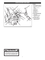
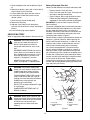
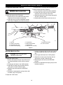
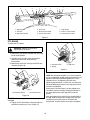
Professional 2-Wheel Tractor
Owner/Operator Manual
Models
985114 - 16 HP
985115 - 8.5 HP
985117 - 13.5 HP
08468600E 6/00
Supersedes 08468600,A-D
Printed in USA
CONTROLS AND FEATURES
ENGLISH
1. Direction Control Lever
2. Steering Brake Handlebar
3. Gear Shift Lever (Hi/Low
Gear)
4. Operator Presence
Control
5. PTO Control
6. Ignition Switch
7. Kick Stand
8. Throttle Control
9. Hourmeter
10. Brake Handle Cross Bar
11. Range Shift Handle (Two
Speed Axle)
12. Parking Brake Handle
(Optional on 8.5HP)
13. Instruction Plate
14. Choke Lever (Robin)
15. Choke Control Knob
(Briggs & Stratton)
1
2
4
8
6
3
9
11
12
14
10
15
4
13
5
4
7
OH0160
WARNING
The engine exhaust from this product
contains chemicals known to the State
of California to cause cancer, birth
defects or other reproductive harm.
OL4030
2
TABLE OF CONTENTS
Controls and Features . . . . . . . . . . . . . . . . . . . . . 2
Troubleshooting . . . . . . . . . . . . . . . . . . . . . . . . . 18
Introduction . . . . . . . . . . . . . . . . . . . . . . . . . . . . . 3
Accessories . . . . . . . . . . . . . . . . . . . . . . . . . . . . 20
Safety . . . . . . . . . . . . . . . . . . . . . . . . . . . . . . . . . . 4
Service Parts . . . . . . . . . . . . . . . . . . . . . . . . . . . 21
Assembly . . . . . . . . . . . . . . . . . . . . . . . . . . . . . . . 8
Specifications. . . . . . . . . . . . . . . . . . . . . . . . . . . 21
Operation . . . . . . . . . . . . . . . . . . . . . . . . . . . . . . 10
Warranty . . . . . . . . . . . . . . . . . . . . . . . . . . . . . . . 22
Maintenance . . . . . . . . . . . . . . . . . . . . . . . . . . . . 13
Service and Adjustments . . . . . . . . . . . . . . . . . 15
Storage . . . . . . . . . . . . . . . . . . . . . . . . . . . . . . . . 18
INTRODUCTION
THE MANUAL
PRODUCT REGISTRATION
Before operation of unit, carefully and completely read
your manuals. The contents will provide you with an
understanding of safety instructions and controls
during normal operation and maintenance.
All reference to left, right, front, or rear are given from
operator standing in operation position and facing the
direction of forward travel.
A warranty registration card must be filled out, signed,
and returned at time of purchase. This card activates
the warranty. Claims meeting requirements during
limited warranty period will be honored.
UNAUTHORIZED REPLACEMENT PARTS
Use only Gravely replacement parts. The replacement
of any part on this vehicle with anything other than a
Gravely authorized replacement part may adversely
affect the performance, durability, or safety of this unit
and may void the warranty. Gravely disclaims liability
for any claims or damages, whether warranty, property
damage, personal injury or death arising out of the use
of unauthorized replacement parts.
MODEL AND SERIAL NUMBERS
Transfer
model & serial
number label
from product
registration
here.
When ordering replacement parts
or making service inquiries, know
the Model and Serial numbers of
your unit and engine.
Numbers are located on the product
registration form in the unit literature
package. They are also printed on a
serial number label, located on the
frame of your unit.
DISCLAIMER
Gravely reserves the right to discontinue, make
changes to, and add improvements upon its products
at any time without public notice or obligation.The
descriptions and specifications contained in this
manual were in effect at printing. Equipment described
within this manual may be optional. Some illustrations
may not be applicable to your unit.
Serial
Number
Label
•
Record Engine Model and Serial numbers here.
3
SAFETY
SAFETY ALERTS
PRACTICES AND LAWS
Look for these symbols to point out
important safety precautions. They mean:
Practice usual and customary safe working
precautions, for the benefit of yourself and others.
Understand and follow all safety messages. Be alert to
unsafe conditions and the possibility of minor,
moderate, or serious injury or death. Learn applicable
rules and laws in your area.
Attention!
Personal Safety Is Involved!
Become Alert!
REQUIRED OPERATOR TRAINING
Obey The Message!
Original purchaser of this unit was instructed by the
seller on safe and proper operation. If unit is to be used
by someone other than original purchaser; loaned,
rented or sold, ALWAYS provide this manual and any
needed safety training before operation.
The safety alert symbol is used in decals on the unit
and with proper operation procedures in this manual.
Understand the safety message. It contains important
information about personal safety on or near the unit.
DANGER: IMMINENTLY HAZARDOUS
SITUATION! If not avoided, WILL RESULT
in death or serious injury.
WARNING: POTENTIALLY HAZARDOUS
SITUATION! If not avoided, COULD
RESULT in death or serious injury.
CAUTION: POTENTIALLY HAZARDOUS
SITUATION! If not avoided, MAY RESULT
in minor or moderate injury. It may also be
used to alert against unsafe practices.
NOTATIONS
NOTE: General reference information for proper
operation and maintenance practices.
IMPORTANT: Specific procedures or information
required to prevent damage to unit or attachment.
4
SAFETY DECALS AND LOCATIONS
ALWAYS replace missing or damaged Safety Decals.
Refer to figure below for Safety Decal locations.
THROTTLE
2
MADE IN U.S.A.
FAST
!
SAFETY FIRST
R E A D T H E O P E R AT O R ' S M A N U A L S B E F O R E O P E R AT I N G
O R S E R V I C I N G T H I S E Q U I P M E N T.
DISENGAGE PTO AND SHIFT INTO NEUTRAL BEFORE
S TA R T I N G E N G I N E .
N E V E R A L L O W C H I L D R E N TO O P E R AT E T H E E Q U I P M E N T.
K E E P H A N D S A N D F E E T AWAY F R O M M O V I N G PA R T S .
S TAY A L E R T F O R P E R S O N S A N D H A Z A R D S .
B E F O R E L E AV I N G O P E R AT O R ' S P O S I T I O N :
– PUT PTO CONTROL IN THE OUT POSITION.
– R E M O V E I G N I T I O N K E Y.
– ENGAGE FWD – REV AND HI – LO CONTROLS.
PUSH OFF
PTO
Units with
Briggs & Stratton
Engines
IGNITION
SLOW
HIGH-PUSH
CHOKE
RANGE
PULL ON
PUSH OFF
LOW-PULL
PULL ON
1
N
Units with
Robin Engines
DA N G E R
TO AVOID SERIOUS INJURY OR DEATH
• Read the operator's manual.
• Do not mow when children or others are
around.
• Look down and behind before and while
backing.
• Never carry children.
• Remove objects that could be thrown by
the blade.
• Go across slopes, not up and down.
• If machine stops going uphill, stop blade and
back down slowly.
• Avoid sudden turns.
• Keep safety devices (guards, shields, switches,
etc.)in place and working.
• Check interlock system per manual before use.
• Understand location and function of all controls.
• When parking on a slope always chock or block
the wheels.
H
L
077478
DANGER
!
4
CAUTION
DO NOT PARK ON SLOPE UNLESS WHEELS ARE CHOCKED.
Units with
Briggs & Stratton
Engines
SAFETY FIRST
READ THE OPERATOR'S MANUAL
BEFORE USING TRACTOR
DISENGAGE ALL CLUTCHES AND
SHIFT INTO NEUTRAL BEFORE
STARTING ENGINE
HANDLE
KEEP
GASOLINE WITH CARE
SHIELDS, GUARDS AND SAFETY
DEVICES IN PLACE
KEEP
HANDS AND FEET AWAY FROM
NEVER LET
MOVING PARTS
CHILDREN OPERATE TRACTOR
BE ALERT FOR DANGER TO BYSTANDERS, PROPERTY AND FOR
TERRAIN HAZARDS
REMOVE
IGNITION KEY BEFORE LEAVING
TRACTOR
ENGAGE FWD - REV
CONTROL AND HI - LO GEAR
CONTROLS WHEN PARKING
•
•
•
BRAKE
••
•
P
3
LOCK
•
•
RELEASE
077247
Units with Steering Brakes
OH0251
1. DANGER! To avoid serious injury or death.
•
Read Operator’s Manual.
Remove objects that could be
thrown by the blade.
Do not mow when children or others
are around.
•
Never carry children.
Look down and behind before and while
backing
5
•
Go across slopes, not up and down.
•
If machine stops going uphill, stop blade
and back down slowly
•
Avoid sudden turns.
•
Keep safety devices (guards, shields,
switches, etc.) in place and working.
•
4. CAUTION
Check interlock system per manual before
use.
•
Understand location and function of all
controls.
•
When parking on a slope always chock or
block the wheels.
Do not park on slope unless wheels are
chocked.
SAFETY RULES
Preparation
Improper use of this tractor can injure people and
damage the equipment. People using or servicing this
tractor must read and follow the instructions in this
manual.
It is important to understand that this manual and any
other Gravely instruction manuals do not cover every
possible danger. It is impossible for Gravely to know of
all possible dangers in operating and servicing the
tractor and attachments.
The purchaser must give these instructions to the
people operating and maintaining this tractor. These
people must use eye and foot protection.
Read this manual, the attachment manual and the
engine manual carefully before operating unit.
2. Safety First
•
Read the operator’s manuals before
operating or servicing this equipment.
•
Disengage the PTO and shift into neutral
before starting engine.
•
Never allow children to operate the
equipment.
•
Keep hands and feet away from moving
parts.
•
Stay alert for persons and hazards.
•
Before leaving operator’s position:
- Put PTO control in the out position.
- Remove ignition key.
- Engage FWD-REV and Hi-Lo controls.
Learn the location and function of all controls.
Know how to stop in an emergency.
Understand and follow each danger, warning, caution
and instruction decal installed on this product.
Never permit children to operate the unit. Do not allow
adults to operate it without proper instruction.
3. Safety First
•
•
Safe operation of this equipment requires your
complete and unimpaired attention at all times. Do not
operate unit after or during the use of drugs or alcohol.
Read the operator’s manuals before using
tractor.
Keep all people and animals away from the operating
area.
Disengage all clutches and shift into
neutral before starting engine.
•
Handle gasoline with care.
•
Keep shields, guards and safety devices in
place.
•
Keep hands and feet away from moving
parts.
•
Never let children operate tractor.
•
Be alert for danger to bystanders, property
and for terrain hazards.
•
Remove ignition key before leaving tractor.
•
Engage FWD-REV control and Hi-Lo gear
controls when parking.
Use caution with gasoline. Gasoline is very flammable
and its vapors are explosive. Keep it in a clean, tight
and approved (Red) container. Never put gasoline in
the fuel tank while the engine is running or hot. Clean
up spilled gasoline before starting engine. Do not fill
fuel tank indoors. Never allow smoking materials,
sparks or flame (match, pilot light, etc.) near mower or
fuel container. Replace fuel tank cap and fuel container
cap securely.
Inspect area of operation and remove all material
which could be thrown by the attachment such as
stones, sticks, wires and other foreign objects.
When transporting the unit, connect the chassis to the
transport vehicle. Never secure by control levers, rods,
or like items that could be damaged.
Replace all parts that become damaged or lost.
Wear hand, foot, head, ear and eye protection. Do not
wear loose clothing which might get caught in rotating
parts.
6
Operation
Before leaving the operator’s position, put the PTO
lever in the “OFF” position, turn off and remove ignition
key. Move the shift control to first gear position.
Be certain that all shields, guards, and interlock
switches are in the correct position and operating
properly.
Do not touch parts which might be hot from operation.
Before attempting to maintain, adjust or service allow
hot parts to cool.
Before starting the engine, put the PTO lever in the
“OFF” position and the gear shift lever in the neutral “N”
position.
Maintenance and Storage
Check the operation of the operator presence controls
before operating the tractor. With either the PTO or the
direction control lever engaged, the engine should run
only if at least one of the operator presence switches is
depressed.
Keep the equipment in good condition. Maintain it as
directed in this manual. Check all hardware at regular
intervals.
Use only Gravely accessories, attachments and
replacement parts.
Do not overspeed the engine. Do not override the
governor.
Before making any repairs or adjustments, disengage
the PTO, turn off and remove the ignition key and wait
for all motion to stop.
To reduce fire hazard and overheating, keep equipment
free of grass, leaves, debris or excessive lubricants.
Worn out mufflers can result in fire or explosion and
should be replaced immediately.
Never store equipment with gasoline in tank inside a
building where fumes may reach an open flame or
spark. Allow engine to cool before storing in any
enclosure.
Refer to Storage if unit is to be stored for extended
periods.
Do not use the equipment in the dark without adequate
lighting.
Keep away from moving parts. Stay clear of the
attachment when the engine is running.
Do not let people other than the operator near the
operating equipment. Never direct discharge of
material towards bystanders. The operator is
responsible for the safety of bystanders.
Operate the attachment only on safe surfaces as
prescribed in the attachment manual. Disengage the
attachment drive when moving the tractor to and from
work areas.
Use a slow speed and engage the shift lever slowly
when operating on slopes.
Travel across slopes, not up and down. Use extreme
caution when changing direction on slopes. Do not
operate on steep slopes.
SPARK ARRESTER
Look for and keep away from hazards such as
drop-offs. Stay alert for holes, rocks and other hidden
hazards in the area of operation.
This product is equipped with an internal combustion
engine. DO NOT use on or near any unimproved, forest
covered or brush covered land unless the exhaust
system is equipped with a spark arrester meeting
applicable local, state or federal laws. A spark arrester,
if used, must be maintained in effective working order
by the operator.
After hitting an object, disengage the PTO, turn off and
remove the ignition key and wait for all motion to stop.
Check for damage. Repair any damage before
restarting unit.
Look behind when operating in reverse. Look for
people and hazards.
Operate only from the operator’s position just behind
the handlebars.
If there is a sudden change in the sound or vibration of
the equipment, disengage the PTO, turn off and
remove the ignition key, wait for all motion to stop and
check for damage. Repair any damage or failure before
restarting unit.
Never run the engine indoors except to move it outside.
Exhaust fumes are dangerous.
Go slowly on slick surfaces. Always be sure of your
footing, keep a firm grip on the handlebars and walk,
never run.
Follow traffic laws when operating on or near a road.
7
ASSEMBLY
TOOLS REQUIRED
Position Handlebar
1. Disconnect Ignition Harness.
2. Position the handlebar right side up.
3. Move the left handle of the handlebar under the
right side of the frame, across the engine and out
between the left side of the frame and the PTO
control.
4. Rotate the handlebar into the mounting position.
5. Reconnect ignition harness.
6. Retain the handlebar in position with four 3/8-16 x
1.25 bolts and locknuts and tighten hardware
(Figure 2).
7. Connect the wiring harness from handlebar to the
unit.
8. Mount the Hi-Lo gear control handle assembly
and pivot to the left handlebar with a 1/2-13 x
3.50 bolt, locknut, and washer (Figure 3).
Phillips Screwdriver, Needle Nose Pliers, Open-End
Wrench: 3/8, 7/16, 9/16 & 3/4 and or Adjustable
Wrench
REMOVE UNIT FROM CARTON
Remove the unit and components from the shipping
container.
Fwd-Rev
Control
Rod
Hi-Lo
Control Rod
Handlebar
Assembly
2
Tractor
Assembly
Optional
Brake Handle
Assembly
3
Brake Rod, RH
6
4
1
5
5
Brake Rod, LH
DH0040
DH0010
1. Hi-Lo Control Handle
2. Brake Handle Grip
3. Hi-Lo Control Rod
Figure 1
ASSEMBLY
Figure 3
2
3
5
3
4
4
1
DH0020
1. Ignition Switch
Harness
2. Ignition Switch
3. Instrument Panel
4. Control Lever
5. Handlebar (Left)
Figure 2
8
4. Extension Rod
5. Adjust and Jam Nuts
6. Left Handlebar
Assemble Steering Brakes (Optional)
Connect Gear Shift and Directional Control
Rods
4
1
2
5
4
3
1
2
7
3
1. Fwd/Rev Control
Handle
2. Right Handlebar
3. Hand Lever Pivot
4. Fwd/Rev Control
Rod
5. Adjust and Jam
Nuts
8
Figure 5
6
5
1. Steering Brake
Handle
2. Instruction Plate
3. Left Hand Brake Rod
4. Right Hand Brake
Rod
Connect the Fwd/Rev and Hi-Lo gear control rods to
the tractor and their respective handles using bushings,
1/4-20 x 1.5 bolts, .281 x .625 x .065 x flat washers and
1/4-20 locknuts. See the gear shift control and
direction control. (Figure 1) and (Figure 5) Adjust per
Owner/Operator Manual.
5. Rear Hitch
6. Adjustment Bracket
7. Bolt and Nut (remove
first)
8. Right Hand Brake
Assembly
Install Hubs and Wheels
For Semi-Pneumatic Wheels: install bushings and
wheel/hub assemblies onto tractor axles. For all other
wheels: install hubs to axles and secure wheels to
hubs with hardware provided.
Figure 4
1. Remove nut and bolt from handle brackets.
(Figure 4)
Left Hand Rod:
2. Hook the rear of the left hand brake rod into the
left side of the brake handle weldment. Before
installing on hitch, place the forward end of the
left hand brake rod below muffler brace.
3. Connect the forward end to the pivot plate with a
.375 x .75 clevis pin, (2) .406 x .812 x .065 flat
washers and a .09 x .75 cotter pin. Insert clevis
pin with cotter pin to the outside of adjustment
bracket. (Figure 4)
Right Hand Rod:
1. Hook the rear of the right hand brake rod into the
right outside end of the brake handle weldment.
2. Place the carriage bolt through the brake handle
3. Put two nylon washers on the bolt between the
handle and the handlebar weldment
4. Retain with another nylon washer, rubber washer,
steel washer and lock nut. (Figure 4)
5. Connect the adjustment bracket to the cam lever
arm with a clevis pin, two .406 x .812 x .065 flat
washers and .09 x .75 cotter pin.
6. Push brake handle grip onto handle.
7. Connect the interlock plug to the wiring harness.
8. Fasten the instruction plate and the brake handle
brackets to the rear hitch with the nut and bolt just
removed and an additional 1/2-13 bolt and
locknut.
9. Adjust brakes per Adjustments.
Install Attachment(s)
Install each attachment following instructions provided.
Charge Battery
See Service Battery in Maintenance.
Fill Engine Fuel Tank
Add clean fuel to fuel tank. See Engine Manual for
correct type and capacity.
Check Engine Oil
Check and add oil if needed. See Engine Manual for
specifications.
Check Safety Interlock System
WARNING: FAILURE OF INTERLOCK,
together with improper operation could
result in death or serious injury.
Lubricate Pivot Points
Put a drop of engine oil on the pivots of the throttle
lever, the direction control lever, the gear shift lever, the
PTO control, and range shift handle.
Check Function of all Controls
WARNING: FAILURE OF CONTROLS
could result in death or serious injury.
Ensure unit runs and performs properly.
9
OPERATION
CONTROLS AND FEATURES
Throttle Lever
NOTE: Read the attachment(s) and tractor manuals
before operating the equipment. Operate the tractor
only from the operator’s position, behind the
handlebars. Service the tractor and attachment before
operating.
Refer to Controls and Features for the following.
The throttle lever is used to control the
engine speed. To increase the engine
speed, move the lever up to the “FAST”
position. To decrease the engine speed,
move the lever down to the “SLOW”
position.
FWD
N
Direction Control Lever
Choke Control
The direction control lever controls the
movement of the tractor. Push the control
forward to go forward. Pull the control back
to move the tractor backwards.
The choke control is used to choke a cold
engine for starting. The choke control is
located on the instrument panel. On 8.5HP
and 13.5HP tractors, push the choke lever
up to the “ON” position to choke the engine. On all
other tractors, pull the choke control knob out to the
“ON” position to choke the engine.
REV
HIGH
PTO Control
Gear Shift Lever
The PTO control is used to connect or
disconnect the engine power to an
attachment. The forward position is “OFF”;
the rearward position is “ON”.
The gear shift lever has two operating
positions. The forward (“HIGH”) position is
the fast gear. The rearward (“LOW”) position
GEAR
is the slow gear.
SHIFT
The gear shift lever also controls the PTO
speed. The forward (“HIGH”) position is the
LOW
fast PTO speed. The rearward (“LOW”)
position is the slow PTO speed.
NOTE: The gear shift lever must be in the neutral
position to engage PTO lever.
NOTE: The gear shift lever must be in the “HIGH” or
“LOW” position to properly transmit power to the PTO
or wheels.
STOP
RUN
START
Ignition Switch
The ignition switch is used to start
(electric start models) and stop the
engine.
Hourmeter
The hourmeter shows total time which the ignition
switch has been in the “ON” position.
Fuse
Range Shift Handle
Electric start models have a fuse to protect the
electrical system.
The range shift handle has two operating
positions. Pull the handle to the rearward
H
(“LOW”) position for the slow speed. Push
L the handle to the forward (“HIGH”) position
for the fast speed.
Rock the tractor back and forth by moving the direction
control lever back and forth while moving the range
shift handle helps align the clutch teeth to engage the
two-speed axle.
Kick Stand
The kick stand is used to hold the tractor level when
there is no attachment on the tractor. The kick stand
must be in the raised position when moving the tractor.
Brake Handlebar
On tractors with steering brakes, the brake handlebar is
used to steer the tractor. Swing the brake handlebar left
for a right turn or right for a left turn.
WARNING: Never move the range shift
handle while on a slope or while the
tractor is moving. Move the handle only
when the tractor is on level ground and
stopped (except for rocking to engage the
clutch as described above).
Parking Brake
The parking brake is used to hold the tractor in position
when not in use.
10
FILL FUEL TANK
4. If the engine is cold, apply the choke. See Engine
Manual for detailed instructions.
5. Set the throttle to the proper starting position.
After the engine starts, adjust the choke as
needed.
6. Pull the starter handle out until compression is
felt in the engine. Then pull with one swift
continuous motion. Hold the starter handle to
allow a slow rewind of the rope.
7. If the engine does not start after six pulls of the
starter, see Troubleshooting.
WARNING: Use caution with fuel. Fuel is
very flammable. Keep fuel in a clean and
tight container. Keep fuel away from fire or
heat. Never put fuel in the fuel tank while
the engine is running or hot. Clean up any
spilled fuel before starting the engine.
Add fuel to the fuel tank as needed. See engine
manual for the correct type and grade of fuel.
1. Put the unit in an open area.
2. Stop the engine and lock the brake.
3. Clean the fuel cap and the area around the fuel
cap to prevent dirt from entering the fuel tank.
4. Remove the cap from the fuel tank.
5. Fill the fuel tank. Be careful not to spill the fuel.
6. Install the cap on the fuel tank and tighten.
7. Clean up any spilled fuel before starting the
engine.
Electric Start Engine
1. Move the direction control lever to the “NEUTRAL”
position.
2. Ensure the PTO control is in the “OFF” position
and the gear shift lever is in the “NEUTRAL”
position.
3. If the engine is cold, apply the choke. See Engine
Manual for detailed instructions.
4. Set the throttle to the proper position. After the
engine starts, adjust the choke as needed.
5. Put the key in the ignition switch. Turn the key to
the “START” position. When the engine starts,
release the key.
6. NOTE: Do not operate the starter for more than
15 seconds. Allow 45 seconds for cooling before
operating the starter again.
7. If the engine does not start after six tries, see
Troubleshooting.
SAFETY INTERLOCK SYSTEM
One of the operator presence control levers must be
depressed so the power take off (PTO) or direction
control lever can be operated.
CAUTION: The operator presence control
is to protect the operator from the moving
parts of the attachment and the powered
moving of the equipment. Operate the
equipment only when the operator
presence control is in working condition.
Stopping the Engine
1. Move the direction control lever to the “NEUTRAL”
position.
2. Move the throttle control to the “SLOW” position.
3. Move the HI/LO to the “NEUTRAL” position and
the PTO control to the “OFF” position.
4. Turn the ignition key to the “OFF” position.
Remove the ignition key before leaving the
tractor.
TO STOP IN AN EMERGENCY
1. Turn the ignition key to "Off".
2. Move the HI/LO to the “NEUTRAL” position and
the PTO control to the “OFF” position.
3. Wait for all moving parts to stop before leaving
the operator’s position.
TO START AND SHUT OFF ENGINE
TO OPERATE UNIT
Before Each Use
Operating the Transmission
Check each item in "Before Each Use" in the
Maintenance Schedule.
Learn to operate the tractor in an open area while
using a slow gear and slow engine speed.
1. Start the engine.
2. Move the gear shift lever to the “HIGH” or “LOW”
position.
3. Move the range shift handle to the “HIGH” or
“LOW” position.
4. Move the throttle lever above the “SLOW” position
(fast enough so that the engine will not stall).
5. Depress an operator presence handle.
Manual Start
1. Move the direction control lever to the “NEUTRAL”
position.
2. Ensure the PTO control is in the “OFF” position
and the gear shift lever is in the “NEUTRAL”
position.
3. Put the key in the ignition switch and turn it to the
“ON” position.
11
NOTE: One of the operator presence control levers
must be held down at all times whenever the
transmission is in gear and/or the PTO lever is in the
“ON” position.
6. To go forward, move the direction control lever
forward until the lever stays in the forward
position. If the lever is not in the full forward
position, the clutch will slip and cause premature
clutch wear.
7. To move backward, hold the direction control
lever to the rear. The lever will return to
“NEUTRAL” when released.
8. To stop the tractor, put the direction control lever
in the “NEUTRAL” position. If the PTO is off, you
can release the operator presence handle.
2. Reduce engine speed.
3. Travel forward to other work area.
PARKING
1.
2.
3.
4.
5.
TO TRANSPORT UNIT
1. Move unit onto transport vehicle.
2. Tie unit down securely. Do not secure by rods,
linkages or controls that may be damaged.
USING THE PTO
To Engage PTO:
TIPS FOR OPERATION
1. Start the engine.
Use slow gears when operating the tractor on rough
ground, slopes, small areas, near buildings or other
obstacles.
2. After the engine is warm, move the throttle lever
just above the “SLOW” position.
3. Move the gear shift lever to the ‘NEUTRAL”
position. Depress an operator presence handle.
4. Pull the PTO control back to the “ON” position
with one continuous, fast pull.
5. Move the throttle lever to the “FAST” position.
6. Move the gear shift lever to the “HIGH” or “LOW”
position.
NOTE: The gear shift lever must be in either the “HIGH”
or “LOW” position to properly power the attachment.
7. Operate the direction control lever for desired
travel.
Use a slow gear and a fast engine speed when
operating a snowblower, rotary cultivator, or a mower in
heavy grass.
Walk behind, never between the handlebars.
To Disengage PTO:
1.
2.
3.
4.
Stop the unit on level ground.
Put the PTO lever in the “OFF” position.
Turn off and remove ignition key.
Move the shift control to first gear position.
Apply parking brake (if equipped.) Pull up on the
brake handle until the brake rod is at the top of
the slot.
Stop the tractor with the direction control lever.
Move the throttle lever to the “SLOW” position.
Move the gear shift to the “NEUTRAL” position.
Push the PTO control in (forward) to the “OFF”
position.
Using the Steering Brakes (optional)
The steering brakes are used when the tractor is being
driven forward.
To make a right turn, push the brake handlebar to the
left.
To make a left turn, pull the brake handlebar to the
right.
CAUTION: Use only the tractor
handlebars to steer when driving in
reverse.
To Travel to Another Work Area
1. Disengage PTO.
12
MAINTENANCE
CHECK FASTENERS
Check Engine Oil
Check Air Cleaner
25
100
200
•
•
Lubricate Control
Linkage
Check Fasteners
Check Clutches
CHECK CLUTCHES
After 25 hours of operation, check the adjustment of
the forward-reverse and gear clutches.
The reverse clutch is adjusted correctly when the
direction control lever stops 15 degrees past vertical to
the rear. The lever should return to neutral position
from reverse.
The forward clutch is adjusted correctly when the
direction control lever is in the full forward position and
the large spring has a coil clearance of .010” (.254mm).
The Hi-Low Gear clutch is adjusted correctly when the
gear shift lever is in the “HIGH” or “LOW” position and
the spring coils are .010” (.254mm) apart.
To adjust clutches, see Service and Adjustments.
•
•
* •
Check Engine Cooling
Check all fasteners after 25 hours of operation to make
sure that they are tight. Replace any fastener that is
missing.
Before Storage
Before Each Use
MAINTENANCE SCHEDULE
•
•
•
•
Adjust PTO Brake
Adjust Slip Clutch
•
•
ADJUST PTO BRAKE
Adjust the PTO brake after every 100 hours of
operation. See Service and Adjustments.
Lubricate Transmission
Service Battery
•
ADJUST SLIP CLUTCH
•
Adjust the slip clutch after every 100 hours of
operation. See Service and Adjustments.
CHECK ENGINE OIL
LUBRICATE TRANSMISSION
Check the engine oil daily, or before each use. Never
operate the engine when the oil level is below the low
mark on the dipstick. See the engine manual for oil
change schedule and detailed instructions.
After every 100 hours of operation, check the level of
the lubricant in the transmission. Never operate the
tractor when the transmission oil level is below the
“LOW” mark on the dipstick.
CHECK AIR CLEANER
Check the air cleaner daily. See the engine manual for
detailed instructions.
1
CHECK ENGINE COOLING
Check the cooling system every 25 hours. Clean all of
the grass and other material from the cooling fins and
intake screen of the engine. If necessary, remove the
engine shrouds to clean the engine.
3
LUBRICATE CONTROL LINKAGE
2
Every 25 hours of operation put a drop of engine oil on
the pivots of the throttle lever, the direction control
lever, the gear shift lever, the PTO control, and range
shift handle.
NOTE: There are no grease fittings on the tractor.
1. Oil Filler Plug
2. Dipstick
3. Dipstick Tube
Figure 6
1. Stop the engine and raise the hood.
2. Make sure that the tractor is level.
13
Battery Electrolyte First Aid
3. Clean the dipstick tube and the dipstick (Figure
6).
4. Remove the dipstick, wipe it with a clean cloth or
towel and put it back in the tube.
5. Pull the dipstick out again and look at the oil.
6. If the oil level is below the low mark on the
dipstick, add oil.
7. Clean the area around the filler plug.
8. Remove the filler plug.
9. Add new, clean lubricant until the dipstick
indicates that the oil level is correct. See Engine
Manual.
10. Install the filler plug and the dipstick.
Follow First Aid directions for contact with battery fluid.
• External Contact: Flush with water.
• Eyes: Flush with water for at least 15 minutes and
get medical attention immediately!
• Internal Contact: Drink large quantities of water.
Follow with Milk of Magnesia, beaten egg or
vegetable oil. Get medical attention immediately!
IMPORTANT: In case of internal contact, DO NOT
induce vomiting!
The tractor is equipped with a low maintenance battery.
Check the fluid level every 200 hours or at the end of
the year. Keep the battery clean. If acid is on the
outside of the battery or the electrical connections are
corroded, clean the outside of the battery with water
and baking soda solution. (Figure 7)
When the battery cables are disconnected, remove the
negative (-) (ground) cable first. When replacing the
battery cable connect the positive (+) cable first. Any
time the battery cables are disconnected, clean the
cable clamps and the battery post or connection.
SERVICE BATTERY
When charging the battery remove it from the unit first.
WARNING: ELECTRIC SHOCK may
result in injury and/or damage to unit.
DO NOT allow objects to come into
contact with both terminals at the same
time.
REVERSE CONNECTIONS may result in
sparks which can cause death or serious
injury. ALWAYS connect positive (+) lead
of charger to positive (+) terminal, and
negative (-) to negative (-) terminal.
ALWAYS connect positive (+) cable
FIRST, and negative (-) cable SECOND.
On tractors not equipped with a maintenance-free
battery, remove the battery and place on a bench or
other place which is well ventilated and acid spill will
not create damage. Fill the battery to the bottom of the
fill tubes with 1.265 specific gravity electrolyte. Twenty
minutes after filling with electrolyte, charge the battery
at 6 to 8 amps for 20 minutes. Follow charger
manufacturer’s instructions for safe procedure. Wait 20
minutes after charging before replacing the battery vent
caps and placing on chassis.
WARNING: EXPLOSIVE GASES from
battery can cause death or serious injury.
ALWAYS keep open flames, sparks or
smoking materials away from batteries.
POISONOUS BATTERY FLUID contains
sulfuric acid. Contact with skin, eyes or
clothing can cause severe chemical burns.
ALWAYS wear safety glasses and
protective gear near battery.
DO NOT TIP any battery beyond 45˚ angle
in any direction.
ALWAYS KEEP BATTERIES OUT OF
REACH of children.
2
1
4
3
2
3
1
WARNING: Battery posts, terminals and
related accessories contain lead and lead
compounds, chemicals known to the State
of California to cause cancer and
reproductive harm. Wash hands after
handling.
4
OH0170
OH0240
1. Fuel Cap
2. Negative Battery
Cable
3. Battery
4. Positive Battery
Cable
Figure 7
14
SERVICE AND ADJUSTMENTS
FORWARD-REVERSE CLUTCH
3. Hold the rear nut and jam with the forward nut.
To adjust the forward clutch (Figure 8) :
1. Put the direction control in the forward position.
2. Loosen the rear set of jam nuts on the control
extension rod in the fwd-rev control rod.
3. Adjust the forward nut until the large spring coils
are .010” (.254mm) apart.
4. Hold the forward nut and jam with the rear nut.
WARNING: Stop the engine before
adjusting the forward-reverse clutch.
To adjust the reverse clutch (Figure 8) :
1. Loosen the jam nuts on the end of the control
extension rod in the fwd-rev control rod.
2. Adjust the rear nut so that the direction control
lever stops 15 degrees past vertical to the rear.
5
2
7
1
7
7
4
1
3
8
9
1
6
7
10
OH0181
1.
2.
3.
4.
Jam Nuts
Fwd-Rev Control Rod
Control Extension Rod
Fwd-Rev Neutral Spring
5.
6.
7.
8.
Large Spring
Brake Rod Assembly
Adjusting Nuts
Fwd-Rev Lever Assembly
9. Adjustment Bracket
10. Cam Lever Arm
Figure 8
HI/LOW GEAR CLUTCH
1. Loosen and separate the jam nuts on the end of
the control extension rod in the Hi-Low control
rod.
2. Put the gear shift lever in the “LOW” position.
3. Adjust the nut (rear) near the spring until the
spring coils are .010” (.254mm) apart.
4. Move the gear shift lever to the “NEUTRAL”
position.
5. Hold the nut adjusted to the spring and jam with
the other (front) nut.
WARNING: Stop the engine before
adjusting the gear clutch.
To adjust the “HIGH” clutch:
1. Loosen and separate the jam nuts on the rear of
the control extension rod in the Hi-Low control
rod.
2. Put the gear shift lever in the “HIGH” position.
3. Adjust the nut (front) near the spring until the
spring coils are .010” (.254mm) apart.
4. Move the gear shift lever to the “NEUTRAL”
position.
5. Hold the nut adjusted to the spring and jam with
the other (rear) nut (Figure 9).
To adjust the “LOW” clutch:
15
3
2
5
2
1
1
1
7
9
1
2
6
8
4
1. Adjusting Nuts
2. Jam Nuts
3. Adjustment Bracket
4. Pivot Plate
5. Brake Rod Assembly
6. Hi-Low Control Rod
7. Large Spring
8. Hi-Low Lever Assembly
9. Control Extension Rod
Figure 9
PTO BRAKE
To adjust the PTO brake:
2
WARNING: Stop the engine before
adjusting the PTO brake.
1
3
1. Remove the attachment and lower the rear of the
tractor to the ground.
2. Carefully clean the front of the transmission.
Remove the quick hitch studs from the
transmission.
3. Remove the quick hitch casting and PTO brake
assembly (Figure 10).
1
1. PTO Brake Bolts
2. Springs
2
3. PTO shaft
Figure 11
2
NOTE: Do not tighten the bolts in a circular sequence,
that is, by tightening the bolt next to one which was just
tightened. The bolts should be tightened in a cross
sequence, that is, by tightening one bolt, then
tightening the bolt which is across from it on the plate.
Continue tightening the bolts in this sequence until all
the bolts are tightened.
Make sure the trunnion block is on the shipper shaft
and held in place by the dog. The dog should rest on
the spiral teeth of the clutch dog plate. Install the
gasket.
Align the splines on the quick hitch shaft with those in
the dog. Slide the quick hitch casting and PTO brake
assembly back into the place on the front of the
transmission. Install the quick hitch studs and tighten.
2
2
1. Quick Hitch Adapter
2. Quick Hitch Stud
Figure 10
NOTE: The attachment gasket must be replaced if
damaged.
4. Tighten all PTO brake bolts until the springs are
solid. Back all bolts up 1/2 turn (Figure 11).
16
SLIP CLUTCH
NOTE: Do not tighten the bolts in a circular sequence,
that is, by tightening the bolt next to one which was just
tightened. The bolts should be tightened in a cross
sequence, that is, by tightening one bolt, then
tightening the bolt which is across from it on the plate.
Continue tightening the bolts in this sequence until all
the bolts are tightened. (Figure 12)
13. Slide the clutch assembly back onto the pinion
shaft.
14. Install the retaining ring and slide the pinion shaft
completely into the transmission.
15. Reinstall the shipper shaft and other parts that
were removed. Make sure the trunnion block is on
the shipper shaft and held in place by the dog.
The dog should rest on the spiral teeth of the
clutch dog plate.
16. Install the gasket.
17. Align the splines on the quick hitch shaft with
those in the dog.
18. Slide the quick hitch casting and PTO brake
assembly back into place on the front of the
transmission.
19. Install the quick hitch studs and tighten.
To adjust the slip clutch:
WARNING: Stop the engine before
adjusting the slip clutch.
1. Remove the attachment and lower the rear of the
tractor to the ground.
2. Carefully clean the front of the transmission.
3. Remove the quick hitch studs from the
transmission.
4. Remove the quick hitch PTO assembly and PTO
brake assembly.
NOTE: The attachment gasket must be replaced if
damaged.
5. Remove the dog and trunnion block.
6. Disconnect the wiring harness from the PTO
brake interlock switch.
7. Remove the shifter parts.
8. Slide the shipper shaft assembly through the top
of the advance casting.
9. Slide the clutch assembly and pinion shaft out of
the transmission.
10. Remove the retaining ring and slide the clutch
assembly off of the pinion shaft.
STEERING BRAKE ADJUSTMENT
(OPTIONAL):
1. Park the tractor in a level area.
2. Put the parking brake handle in the “OFF” (down)
position.
3. Loosen the jam nuts on the right and left brake
rod assemblies (Figure 8)(Figure 9).
4. Turn the adjusting nuts until the brake handle
cross bar is parallel with the instrument panel.
(See Controls and Features.)
5. Move the brake handlebar all the way to the right
and measure the distance from the right end
edge of the brake handle cross bar to the right
side of the instrument panel.
6. Move the brake handlebar all the way to the left
and make the same measurement on the left.
7. Adjust the nuts until the difference between the
two measurements is 1/2” to 3/4” (13 to 19mm).
8. Turn both adjusting nuts the same amount,
clockwise to increase the measurement
difference or counterclockwise to decrease the
measurement difference.
9. Tighten the jam nuts.
10. Loosen the jam nuts below the compression
spring on the right side of the tractor and adjust
until one has the desired tension for the right
brake.
11. Tighten the jam nuts.
11. Turn all of the jam nuts counterclockwise to
loosen.
12. Torque bolts to 70 in. lbs. in two stages. First
tighten bolts to 20 in. lbs. in pattern shown
(Figure 12). Then tighten to 70 in. lbs. in same
pattern.
6
1
3
4
2
5
Figure 12
17
STORAGE
Check each item in "Before Storage" in the
Maintenance Schedule. See Engine Manual for
detailed instructions on preparing the engine for
storage.
NOTE: Do not use harsh or abrasive cleaners on any
painted surface. Do not allow gasoline or oil to remain
on any surface.
3. Refer to the engine manual and prepare the
engine for storage.
4. Charge the battery initially and then every three
weeks.
When The Tractor Will Not Be Operated For
Two Months Or More:
1. Do the daily and 25-hour maintenance, but do not
add gasoline.
2. Clean the tractor. Paint or oil bare metal surfaces
to prevent rust.
IMPORTANT: NEVER spray unit with water or store
unit outdoors. Water can seep into sealed bearings,
which are sealed against dirt and debris only, causing
reduced component life.
To Put The Tractor Into Service:
1. Refer to the engine service manual and prepare
the engine for service.
2. Charge the battery.
3. Put fresh, clean gasoline in the fuel tank.
TROUBLESHOOTING
PROBLEM
PROBABLE CAUSE
CORRECTION
Starter will
not operate
when ignition
key is turned
to “S”
position.
1. Fwd-Rev lever in “FORWARD”
position
2. PTO engaged
3. Loose battery cable(s)
4. Blown fuse
5. Discharged battery
6. Defective solenoid switch
7. Defective starter
1.
2.
3.
4.
5.
6.
7.
Solenoid
switch clicks
but starter will
not operate
when ignition
is turned to
“S” position.
1. Discharged battery
2. Loose battery cable
3. Defective starter
1. Charge the battery. See Maintenance.
2. Clean and tighten battery connections.
3. Replace starter. Call your dealer.
Engine starter
operates but
engine will
not start
when ignition
switch is
turned to “S”
position.
1. Fuel tank empty
2. Fuel shut-off valve at the fuel tank
turned off
3. Relay defective
4. Engine failure
1.
2.
3.
4.
Fill tank with clean, fresh fuel.
Turn fuel shut-off valve on.
Replace relay. Call your dealer.
See Engine Manual
Engine starts
but runs
roughly.
1.
2.
3.
4.
5.
1.
2.
3.
4.
5.
Move engine choke to "OFF".
Clean air cleaner. See engine manual.
Clear obstruction from fuel cap vent.
See Engine Manual
See Engine Manual
Engine choke in “ON” position
Restricted air cleaner element
Restricted fuel cap vent
Engine carburetor malfunction
Engine electrical system trouble
18
Place Fwd-Rev lever in neutral position.
Disengage PTO.
Clean and tighten battery connections.
Replace fuse.
Charge battery.
Replace. Call your dealer.
Replace starter. Call your dealer.
PROBLEM
PROBABLE CAUSE
CORRECTION
Engine stops
when PTO or
Fwd-Rev is
engaged.
1. Operator presence handle not
pressed
2. Operator presence handle out of
adjustment
3. Faulty switch
1. Press and hold at least one operator
presence control.
2. Call your dealer.
3. Replace switch. Call your dealer.
The tractor
will not move
when the
direction
control lever
is moved to
‘FORWARD”
or
“REVERSE”.
1. Gear shift lever in “NEUTRAL”
position
2. Range shift handle in ‘NEUTRAL”
position
3. Fwd-Rev clutch needs adjustment
4. Internal transmission damage
1. Place gear shift lever in Hi or Low position.
2. Place range shift lever in Hi or Low
position.
3. Adjust Fwd-Rev clutch. See Adjustments
or call your dealer.
4. Call your dealer.
Attachment
will not
operate.
1. Gear shift lever in “NEUTRAL”
position
2. Attachment jammed or damaged
3. Attachment slip clutch out of
adjustment or damaged
4. Shipper shaft and clutch dog loose
and out of adjustment
1. Place gear shift lever in Hi or Low position.
2. Clear debris from attachment. Repair
before restarting engine.
3. Adjust or repair.
4. Adjust or repair.
Attachment
operates
slowly
1. Hi/Low clutch worn
2. Attachment slip clutch needs
adjustment or repair
3. Attachment damaged
4. Engine problems
1.
2.
3.
4.
Transmission
will not go
into “HIGH”
range. Jumps
out of range
1. Debris blocking the linkage
2. Rust on the clutch sliding pin
3. Shifting clutch dogs worn/damaged
1. Clear debris from linkage. Repair before
restarting engine.
2. Clean or replace.
3. Adjust or replace.
19
Adjust or repair.
Adjust or repair.
Repair
See Engine Manual
ACCESSORIES
ACCESSORIES
See your authorized Gravely dealer to add these
optional accessories.
Mowing
78506400
Tractor Cover
78506500
Retro-Fit Kit
78506600
High Lift Blade Kit, 40” Mowers
78500600
30” Mower Drive (Short)
78506700
High Lift Blade Kit, 50” Mowers
78500700
30” Mower Drive (Long)
78506800
Sand Blade Kit, 40” Mowers
78500800
40” Commercial Mower Drive Prior to
5000 Series
78506900
Sand Blade Kit, 50” Mowers
78802700
Handle Interlock Kit
78500900
40” Commercial Mower Drive On 5000
Series & Newer Models
78501000
42” Sickle Mower Cutter Bar
78501100
Chain Guard
See your authorized Gravely dealer to add these
optional attachments.
78501200
Front Mount Kit
885001
30” Mower Deck
78501300
Front Anti-Scalp Roller
885002
30” Mower Deck
78501400
Rear Anti-Scalp Roller
885003
40” Mower Deck
78501500
30” Weight Kit
885004
40” Commercial Mower Deck
785009
Drive not included
ATTACHMENTS
Garden
78501600
Rotary Cultivator Drive
885007
50” Mower Deck
78501700
Planter Drill (Less Blades)
885008
32” Flail Mower
78505900
10” Planter Drill Blade
885009
42” Sickle Mower
78506000
19” Planter Drill Blade
885010
Rotary Plow
Snow Removal
885011
Cultivator
73500700
Snowblower Drift Bar
833007
32” Sno Thro
78501900
48” Snow Dozer Hitch
885014
48” Dozer Blade
78502000
48” Snow Dozer Counterweight Kit
885015
44” Brush
78502100
48” Snow Dozer Skid Kit
885013
Winter Cab
78502200
Power Brush Conversion Kit
885016
Cart
78502300
44” Power Brush Completing Kit
885017
Sulky
78502400
Tire Chains (4:00 x 8) (Pair)
78502500
Tire Chains (7:50 x 8) (Pair)
78502600
Tire Chains (8:50 x 8) (Pair)
Miscellaneous
78502700
Pow-R-Steering Kit
78502900
Quick Hitch Pin Kit
78503000
Attachment Adapter Kit
78503100
Dual Wheel Spacers
78509800
Dual Wheel Spacers
78503200
Trailing Hitch Kit
78510600
Coupler Strut Weldment Kit
78503400
Remote Air Cleaner Kit
78503500
High Performance Air Cleaner Kit
78503600
QS Muffler Kit
78506100
Triple Purpose Wrench
20
SERVICE PARTS
Be sure to always use genuine Gravely parts to keep
your Sno-Thro running like new.
Part no.
Qty
Description
03621100
1
Battery (Robin Model)
04202200
1
Battery (Briggs Model)
21527200
1
Air Cleaner (Robin EH25)
21527300
1
Assembly-Air Cleaner
Element (Robin EH41)
21527100
1
Air-Cleaner Element (Robin
EH25)
08811700
1
Fuel-Filter (Robin)
21526800
1
Spark Plug (Robin EH25)
21526900
1
Spark Plug (Robin EH41)
08861651
3
Blade-50”
03498451
3
Blade-40”
08526151
1
Blade-30”
07226600
1
Belt-50” Mower drive
07226700
1
Belt-40” Mower drive
SPECIFICATIONS
Model Number
985114
985115
Height - in (cm)
36.5 (92.7)
Length - in (cm)
58 (147.3)
Width - in (cm)
25 (63.5)
Weight - lbs (Kg)
425 (192.8)
985117
420 (183)
Wheel Size - in (cm)
428 (195)
4.0 x 8 (10.2 x 20.3) Stud Tread
4.0 x 8 (10.2 x 20.3) Trac Tread
18 x 8.5-8 (45.7 x 21.6-20.3) Turf Chief
18 x 8.5-8 (45.7 x 21.6-20.3) Turf Saver
16 x 5 x 3 (40.6 x 12.7x 7.2) Semi-Pneumatic Ground Grip
Tire Pressure
Steering Brakes
Engine
See Tire Sidewall
7 x 1.75 Drum Type
N/A
7 x 1.75 Drum Type
16 HP Briggs & Stratton
8.5 HP Robin
13.5 HP Robin
EH25
EH41
16HP
Engine Operating Fast Idle Speed - RPM
3300-1600
Fuel
See Engine Manual for type and grade
Fuel Tank Capacity - gal (Liters)
1.5 (5.68)
Transmission Oil Capacity - qt (Liters)
5.0 (4.73)
Transmission Oil Type
SAE 30
Engine Oil Type and Capacity
Battery
See Engine Manual
12V BCI Group 22F,
42amp/Hr
21
12V BCI Group, 230 CCA. 29 min. Reverse Capacity
WARRANTY
2 Year Limited Warranty
Gravely Division of Ariens Company
655 West Ryan Street
P.O. Box 157
Brillion, WI 54110-0157
920-756-2141
Fax 920-756-2407
Ariens Company hereby warrants to the original consumer purchaser
that all Gravely Two-Wheel, Professional G, Pro, and ProMaster products
will be free from defects in material and workmanship for a period of
two (2) years from the date of purchase or 1000 hours, whichever
comes first.
Protection Plan
Ariens Company will repair or replace any part found upon examination
by the Ariens Company to be defective. Such repair or replacement
will be free of charge to the purchaser (labor and parts), except as
noted below.
This warranty is subject to the following exceptions, conditions, and limitations:
Usage Requirement
The duration of this warranty shall be ninety days or 1000 hours, whichever comes first, if the product is rented or leased.
Purchaser’s Responsibilities
• The purchaser must perform maintenance & minor adjustments
per the operator’s manual.
• The purchaser must notify Ariens Company or an authorized
Gravely service representative of the need for warranty service.
• The purchaser must transport the product to and from the place
of warranty repair.
Product Registration
• The Gravely dealer must fill out and return the warranty
registration card to validate the warranty.
Service Parts and Accessories
• Service parts and accessories not purchased with the product
covered by this warranty are warranted to be free of defects
for a period of ninety (90) days following the date of purchase,
and will be replaced free of charge (except for labor).
Service
• Warranty service must be done by an authorized Gravely dealer.
To find a Gravely dealer near you, contact Ariens Company.
Exclusions (No Warranty)
• Normal maintenance, services, and normal replacement items,
such as spark plugs, oil, oil filters, air filters, mufflers, belts,
tires, shoes, runners, scraper blades, shear bolts, mower blades,
mower vanes, headlights, light bulbs, knives, etc. are not covered
by this warranty.
• Any equipment which has been altered, misused, misassembled,
improperly adjusted, neglected, or damaged by accident is not
covered by this warranty.
• Service completed by someone other than an authorized
Gravely dealer is not covered by this warranty.
• Any attachment not approved by Gravely nor any parts that
are not genuine Gravely service parts are not covered by this
warranty.
• Engines and engine accessories are covered only by the
warranty made by the engine manufacturer, and are not covered
by this warranty.
• This warranty applies only to products purchased in the United
States (including Puerto Rico) and Canada. In all other countries,
contact place of purchase.
Battery Warranty Prorated
• One to three months - Free replacement
• Four to twelve months - Prorated over 12 months
Ariens Company may from time to time change the design of its products. Nothing contained in this warranty shall be construed as
obligating Ariens Company to incorporate such design changes into previously manufactured products, nor shall such changes be
construed as an admission that previous designs were defective.
LIMITATION OF REMEDY AND DAMAGES
Ariens Company’s liability under this express warranty, and under
any implied warranty that may exist, is limited to repair or replacement
of any defective part. In no event shall Ariens Company be liable
for incidental, special, or consequential damages (including lost
profits). This warranty gives you specific legal rights. You may also
have other rights which vary from state to state. Some states do
not allow the exclusion of incidental or consequential damages, or
limitations on how long an implied warranty lasts, so the above
limitations and exclusions may not apply to you.
DISCLAIMER OF FURTHER WARRANTY
Ariens Company makes no warranty other than
what is expressly made in this warranty. If the law
of your state provides that an implied warranty of
merchantability, or an implied warranty of fitness
for a particular purpose, applies to Ariens Company,
any such implied warranty is limited to the duration
of this express warranty.
Form: GLW2-062399
22
GRAVELY
A Division of Ariens Company
655 West Ryan Street
P.O. Box 157
Brillion, WI 54110-0157
920-756-2141
Fax 920-756-2407
www.gravely.com