1
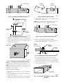
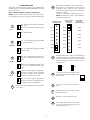
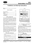
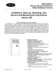
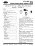
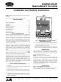
ZONEKIT2ZCAR
WeatherMaker® Two-Zone
Visit www.carrier.com
Installation and Start-Up Instructions
NOTE: Read the entire instruction manual before starting the
installation.
This symbol → indicates a change since the last issue.
TABLE OF CONTENTS
PAGE
Safety Considerations.....................................................................1
Installation Considerations.............................................................1
Introduction ....................................................................................1
Installation...................................................................................1-4
Sequence Of Operation...............................................................4-7
Thermostat Wiring ......................................................................6-8
Care And Maintenance ..................................................................8
Troubleshooting ........................................................................9-11
Wiring Diagrams.....................................................................12-16
Wiring Diagram Notes.................................................................16
SAFETY CONSIDERATIONS
Improper installation, adjustment, alteration, service, maintenance,
or use can cause fire, electrical shock, or other conditions which
may cause personal injury or property damage. Consult a qualified
installer, service agency, or your distributor or branch for information or assistance. The qualified installer or agency must use
factory-authorized kits or accessories when modifying this product. Refer to the individual instructions packaged with the kits or
accessories when installing.
Follow all safety codes and wear safety glasses. Have fire
extinguisher available. Read these instructions thoroughly and
follow all warnings or cautions attached to the unit. Consult local
and state building codes and Sheet Metal and Air Conditioning
National Association (SMACNA) for special installation requirements.
Recognize safety information. This is the safety-alert symbol .
When you see this symbol on the unit or in instructions and
manuals, be alert to the potential for personal injury.
Understand the signal words DANGER, WARNING, or CAUTION. These words are used with the safety-alert symbol. DANGER identifies the most serious hazards which will result in severe
personal injury or death. WARNING signifies hazards which
could result in personal injury or death. CAUTION is used to
identify unsafe practices which would result in minor personal
injury or product and property damage.
INSTALLATION CONSIDERATIONS
1. Install in non-condensing area with ambients between 32°F
and 150°F.
2. Use vibration isolators (flex connectors) on zone dampers and
ductwork to minimize noise.
3. Place dampers away from areas that may be noise sensitive.
®
COMFORT ZONING
Y2 T'stat Equpimt
RC-RH
Jumper
Y1
HP
Fnc
R
Fnc
HP Emergency
W1
Heat
W2 DTO Fnc Ht
On
C
Off w/oF
Off
On w/F
G Y2 Y1 R W1 W2
C
Sensors
HP
Duct
24 VAC
Z C1
o
n Op
e
1 C
Z C1
o
n Op
e
2 C
SYSTEM
G Y1 Y2
WARNING!
3
HOT parts
under this label
Rev
W1 W2
RC B O Y2 Y1 W1 W2 G
RH
Equipment Term.
A97292
Fig. 1—WeatherMaker Two-Zone System
(Shown Without Cover)
6. Load calculations must be performed to determine equipment
size. Equipment selection is matched to block load. It is
imperative equipment is not over sized.
7. Ductwork must be designed based off the sum of peak plus 25
percent oversize. It is imperative ductwork is not under sized.
INTRODUCTION
The WeatherMaker Two-Zone System allows the air conditioning
and heating equipment to control temperatures in 2 distinct spaces
or zones within a building. Each zone has independent temperature
settings controlled by a thermostat.
NOTE: Thermostats are purchased separately.
The comfort temperature settings can change automatically
through the use of schedules if programmable thermostats are
selected. This allows WeatherMaker Two-Zone to change the
temperature settings in zones to reflect occupancy or usage. The
WeatherMaker Two-Zone System uses motorized air volume
control dampers (also called zone dampers) to regulate the flow of
conditioned air into the zones.
INSTALLATION
Step 1—Check Equipment and Jobsite
INSPECT EQUIPMENT — File claim with shipping company,
prior to installation, if shipment is damaged or incomplete.
4. TXV is required in air conditioning and heat pump applications.
5. Use separate isolated transformer to supply power to WeatherMaker Two-Zone Center. (40va minimum, class 2, transformer, field supplied)
Manufacturer reserves the right to discontinue, or change at any time, specifications or designs without notice and without incurring obligations.
Book 1 1 4 4
PC 101
Catalog No. 809-519
Printed in U.S.A.
Form ZONEKIT-10SI
Pg 1
10-97
Replaces: ZONEKIT-8SI
Tab 3a 5a 2a 5a
Step 2—Wiring
insulate over the actuator assembly. Make sure insulation does not
interfere with operation of actuator.
Before insulating the ductwork, check for proper damper operation. Apply 24vac between COM and OPN to open the damper and
COM and CLS to close the damper. (See Fig. 3.) The damper will
modulate counter-clockwise to open and clockwise to close.
To prevent personal injury or possible equipment damage,
disconnect the power supply before routing wire.
MOUNTING
HUB
AIRFLOW
NOTE: Use No. 18 AWG color-coded, insulated (35°C min)
wire. If thermostats are to be located more than 100 ft from the
WeatherMaker Two-Zone Center as measured along the control
voltage wires, use 16 AWG colored-coded wires to avoid excessive voltage drop. All wiring is run back to the WeatherMaker
Two-Zone Center.
AIRFLOW
All wiring must comply with local, state, and national codes.
POSITION
INDICATOR
Step 3—Install WeatherMaker Two-Zone
90
NOTE: WeatherMaker Two-Zone is approved for indoor use
only and should never be installed with any of its components
exposed to the elements. Do not mount WeatherMaker Two-Zone
Center where it will be accessible to children. Do not locate the
center in areas of the home that are noise sensitive since relays are
energized and de-energized during operation and may be an
annoyance. Install WeatherMaker Two-Zone in an area with a
temperature range between 32°F and 150°F.
45
ACTUATOR
HOUSING
CLS
COM
OPN
0
QUICK BLADE
RELEASE
BUTTON
(RED)
Install WeatherMaker Two-Zone center in a vertical position.
Locate in an area that is easily accessible in case servicing should
be required.
MOUNTING
BRACKET
FIELD
INSTALLED
POWER WIRING
To prevent possible damage to the WeatherMaker Two-Zone
Center, do not mount on plenum, ductwork, or flush against
furnace.
Fig. 3—Damper 24-vac Connections
A95096
If in an emergency it becomes necessary to force a damper open
manually, press in red quick blade release button with 1 hand and
turn mounting hub to reposition the damper shaft. Release button
to hold damper shaft in the new position.
Step 4—Install Zone Dampers
IMPORTANT: If conditions exist for possible condensing, the
motor must be positioned for adequate draining. (See Fig. 2.)
To avoid noise and vibration, do not hard mount dampers to any
solid structure such as joists.
NOTE: If a multi-damper enabler is used to link dampers
together, then add 5va per damper to the transformer power supply
rating. Reference multi-damper enabler Installation Instructions.
ROUND METAL DUCTWORK
IMPORTANT: If application exists with all metal ductwork
without insulation, flex connectors should be used on each end of
the zone dampers to avoid noise and vibration.
Zone dampers may be installed in any direction.
Install dampers so the actuator is visible for inspection and
accessible in the event it would ever need service. The black mark
on the end of the damper shaft represents the position of the
damper blade.
DAMPER
ANGULAR
ROTATION
STOPS
1. Crimp end of branch duct.
2. Slip end of flex connector over zone damper and use selftapping sheet metal screw to secure. (See Fig. 4.)
MOUNTING
BRACKET
SUPPLY
FLEX
CONNECTOR
ZONE DAMPER
Fig. 4—Round Metal Ductwork
A95129
3. Properly seal joint using duct tape, mastic, or other approved
method. Do not allow mastic to come in contact with actuator.
4. Insulate damper using 1-1/2-in. to 2-in. insulation. (Check
your local codes.) (See Fig. 5.)
NOTE: All zone dampers and ductwork must be properly supported according to local codes or SMACNA standards.
ACTUATOR
Fig. 2—Damper Motor Positioning
A95128
RECTANGULAR METAL DUCTWORK
NOTE: Insulate damper using 1-1/2 in. insulation (check local
codes). In areas where excessive condensing may occur, carefully
1. Make connections using S-lock and drives. (See Fig. 6.)
2
1
/ 2 ″ STEEL STRAP
FLEXIBLE
DUCT
A95130
Fig. 5—Insulated Round Metal Ductwork
ZONE
DAMPER
Fig 8—Round Flexible Ductwork
A95132
4. Insulate damper using 1-1/2-in. to 2-in. insulation. (Check
your local codes.) (See Fig. 9.)
NOTE: All zone dampers and ductwork must be properly supported according to local codes or SMACNA standards.
S-LOCK
1/ 2 ″
STEEL STRAP
SUPPLY
AIR DUCT
DRIVE
ZONE
DAMPER
Fig. 6—Rectangular Metal Ductwork
A95133
A92478
Fig. 9—Insulated Round Flexible Ductwork
2. Properly seal joint using duct tape, mastic, or other approved
method. Do not allow mastic to come in contact with actuator.
RECTANGULAR FIBROUS GLASS DUCTWORK
1. Insert 1 end of zone damper into 1 end of fibrous glass
ductwork approximately 2 to 3 in. (See Fig. 10.)
3. Insulate damper using 1-1/2-in. to 2-in. insulation. (Check
your local codes.) (See Fig. 7.)
FIBROUS
GLASS
DUCTWORK
1 1/2 " TO 2"
INSULATION
FIELD
SUPPLIED
SCREWS
ZONE
DAMPER
2″ TO 3″
A92480
Fig. 10—Rectangular Fibrous Glass Ductwork
2. Screw field-supplied screws and tabs into zone damper.
3. Properly seal joint using duct tape, mastic, or other approved
method. Do not allow mastic to come in contact with actuators
A95131
Fig. 7—Insulated Rectangular Metal Ductwork
4. Insulate damper using 1-1/2-in. to 2-in. insulation. (Check
your local codes.) (See Fig. 11.)
NOTE: All zone dampers and ductwork must be properly supported according to local codes or SMACNA standards.
NOTE: There should be a minimum of 4 ft between the zone
damper and the first branch duct if more than 1 branch duct is
downstream of the zone damper.
ROUND FLEXIBLE DUCTWORK
1 1/ 2 ″ TO 2″
INSULATION
1. Slip 1 end of flexible ductwork over 1 end of zone damper.
(See Fig. 8.)
2. Secure the flexible duct to zone damper using SMACNA or
other approved method.
A95134
3. Properly seal joint using duct tape, mastic, or other approved
method. Do not allow mastic to come in contact with actuator.
Fig. 11—Insulated Rectangular Fibrous Glass
Ductwork
3
Step 5—Install Barometric Bypass Damper
• Energize HVAC equipment fan.
• Energize heating or cooling equipment. The equipment may be
a compressor, furnace, strip heater, etc.
• Set zone damper to the open or closed position based upon
individual zone demand.
• Energize additional stages of heating or cooling if the thermostat
demand warrants.
• Turn off heating or cooling equipment when all zones are
satisfied.
• Open all zone dampers when equipment is turned off (after 90
sec delay).
This is the basic sequence of operation for the WeatherMaker
Two-Zone System. The actual control of the dampers, HVAC
equipment, and system fan will change with the configuration of
the system. Depending upon the configuration, WeatherMaker
Two-Zone can control heat pumps, furnaces, and dual fuel
applications, (dual fuel will require a third party relay interface).
Step 2—Selection of a System Mode
The first step in any heating or cooling cycle requires WeatherMaker Two-Zone to receive an input from any thermostat located
in a zone. WeatherMaker Two-Zone will then prepare to operate
the heating or cooling equipment as requested by the thermostat.
(See Fig. 12.)
Step 3—Pre-Positioning Dampers and Starting
System Fan
In order to minimize noise and enhance system operation, WeatherMaker Two-Zone maintains fully open zone dampers prior to
starting the system fan or the heating/cooling equipment. The
intent is to provide the HVAC equipment with unrestricted
ductwork and to reduce pressure surges. WeatherMaker Two-Zone
also fully opens the dampers whenever a heating or cooling cycle
is completed (this is done after a 90 sec delay). All zone dampers
will remain fully open until the next heating or cooling cycle.
The other reason for opening the dampers is to provide unrestricted
ductwork to other equipment which is not directly controlled by
WeatherMaker Two-Zone. One example may be a Heat Recovery
Ventilator. If WeatherMaker Two-Zone is not actively controlling
the HVAC system, then it must not impose any control influences
(such as closed zone dampers) on the system and prevent proper
operation of other devices.
Only the zone 1 thermostat controls continuous fan operation.
When the zone 1 thermostat has the fan selector switch in the
AUTO position, the fan will operate only when the heating and
cooling equipment is operating. When the zone 1 thermostat has
the fan selector switch in the ON position, the fan will operate
continuously. Zone 2 will not control this.
Step 4— HVAC Equipment Connections
The WeatherMaker Two-Zone relay outputs are shown in Table 1.
The Y1 and Y2 contacts are used for the compressor contactor
only. WeatherMaker Two-Zone operates the heat pump by energizing the compressor contactor and controlling the reversing
valve through the O relay output. The W1 and W2 contacts are
always used for heat sources. These are heating only units such as
furnaces, strip heaters, etc. The relay outputs for WeatherMaker
Two-Zone are shown in Table 1.
NOTE: The barometric bypass damper is a critical part of the
WeatherMaker Two-Zone System for control of minimum airflow
and noise reduction. It is recommended that the bypass be
installed.
The bypass should be installed according to local codes and
SMACNA standards. Be sure the bypass is properly supported.
For proper installation, refer to the Installation Instructions packaged with the barometric bypass.
Failure to properly install the bypass damper can cause
permanent damage to the HVAC equipment. For single-speed
furnace applications, the bypass air must never exceed 25
percent.
Step 6—Install Leaving Air Temperature Duct Sensor
Locate duct temperature sensor in main supply trunk after heating
and cooling coil and before the bypass damper and before the first
branch. The duct sensor must be radiant shielded to prevent heat
from affecting the correct air temperature.
1. Drill 1/4-in. hole at location in supply trunk where sensor will
be installed.
2. Insert sensor in hole and use as template to mark 2 mounting
holes.
3. Drill two 1/16-in. holes to accept No. 6 screws through
pre-drilled holes in duct temperature sensor back plate.
4. Use 2 No. 6 sheet metal screws to mount duct temperature
sensor to unit.
5. Connect sensor to 2-conductor wire using provided wire nuts.
(See Fig. 12 for connection to equipment controller.)
Step 7—Install Heat Pump (HP) Temperature Sensor
The HP temperature sensor is required in all heat pump/fan coil
installations. It is not used in dual fuel (heat pump/furnace
installation.) It measures the indoor coil temperature. The sensor is
to be installed downstream of the indoor coil, but before the
electric heaters. It can be installed through the wall of the fan coil
or may be located entirely inside the fan coil near the blower inlet.
Anchor firmly in place with cable ties so that it cannot interfere
with the blower wheel. To activate the HP temperature sensor,
remove factory supplied resistor from HP terminal block and
replace with sensor leads. When activated, the HP temperature
sensor has built in LAT set points of 50°F and 45°F in the cooling
mode, and 105°F and 110°F in the heating mode. This is
non-adjustable. (See Fig. 12 for connection to WeatherMaker
Two-Zone center.)
SEQUENCE OF OPERATION
Step 1—Sequence of Events for a Normal Heating or
Cooling Cycle
The thermostats will determine if active heating or cooling is
required. If so, the WeatherMaker Two-Zone System will perform
the following:
• Make sure all zone dampers are fully open.
Table 1—Available Heating and Cooling Stages Versus System Type
TYPE OF HVAC
REVERSING VALVE
REVERSING VALVE
COOLING STAGE 1 COOLING STAGE 2
HEAT STAGE 1 HEAT STAGE 2
EQUIPMENT USED
O
O
Single-Stage Heat
Y1
—
Energized
Y1/W1
W2
De-energized
Pump
2-Stage Heat Pump
Y1
Y2
Energized
Y1/W1
W2
De-energized
Cooling Only, any
Y1
Y2
—
W1
W2
—
Heater Type
4
If you encounter a situation where 1 zone seems to have poor
ductwork, then the WeatherMaker Two-Zone system is capable of
reverting back to a fully open, constant-volume system. If this
condition persists, it should always be looked upon as an indication
of a HVAC problem, not a WeatherMaker Two-Zone problem.
In automatic changeover, the zoning system works on a first come
first serve basis. If 1 zone is calling for heating and the other for
cooling, the zone which sent its demand to the I/O center first will
operate the equipment in that mode until that zone is satisfied.
Step 5—Duct Temperature Optimizer (DTO)
For Monitoring Leaving Air Temperature
Step 6—Electronic Thermostat Connection with
WeatherMaker Two-Zone Control
As the WeatherMaker Two-Zone System operates through a
heating or cooling cycle, the zone demands will change. This
changes actual load that is applied to the HVAC equipment. If the
zone airflow decreases, the cooling equipment will tend to lower
supply-air temperatures which could tend to exceed the LAT trip
limits. Conversely, the heating equipment will tend to raise the
supply-air temperatures which could exceed high trip limits. In
cooling, when the LAT reaches the non-adjustable low temperature trip limit (50°F) the LAT algorithm begins operating, closed
dampers are initially opened 3 positions, then 1 position every 20
sec there after until full open. WeatherMaker Two-Zone will not
shut down second-stage cooling (if used); however, if temperature
continues to drop to 45°F, the zoning system will turn off both
stages of cooling. If the temperature improves, the system will stay
in the duct temperature optimizer mode until the LAT reaches
55°F or higher. At 55°F the LAT algorithm will reset and return
dampers to their original position. In the heating mode, WeatherMaker Two-Zone will perform the same duct temperature optimization. The trip limits will be determined by the jumper setting.
(See Fig. 12.) This will continue until the LAT problem is
corrected.
Carrier electronic non-programmable and programmable thermostats can be connected to the WeatherMaker Two-Zone. See
pre-sale literature for thermostat part numbers.
NOTE: The zone control board is only capable of 2-stage heat
and 2-stage cool operation. Fig. 13 and 14 will reflect these
applications only. Review and understand the following items
before installing.
THERMOSTAT SETUP
1. Thermostat will not operate unless both R and C are connected
to zone module input.
2. If selected thermostat is a heat pump (HP) or 2-speed (2S)
model, convert thermostat to air conditioning operation. This
will assure that Y signals are generated for cooling, and W
signals are generated for heating from thermostat to zone
module input. The thermostat O/W2 output will now be the
second-stage heat call. If installation is a heat pump system,
the zone control board will provide proper output signal to
heat pump.
3. Select "Zoning" option on thermostat. This will disable the
Timeguard and 4-cycle per hr (cph) protection built into
thermostat. Let zone control board perform the Timeguard and
cycle protection. Refer to thermostat Installation Instruction
under Zoning for more detail.
This control helps WeatherMaker Two-Zone System cope with
installations where the air conditioning system may suffer from
poor ductwork, improperly sized heating or cooling equipment,
and/or improper settings of the barometric bypass damper. This
control is especially useful in retrofit applications where the size
and routing of the ductwork may not be entirely known or
satisfactory.
4. The zone 1 thermostat is the only thermostat that can control
continuous fan operation with zoning. Connect G between
zone 1 thermostat and zone 1 input on zone control module.
The duct temperature optimizer works by controlling how cold or
hot the air inside the supply-air duct gets by monitoring the
temperature of the air inside the supply-air system.
5. Follow all safety and installation considerations outlined in the
thermostat Installation Instructions.
ZONE CONTROL BOARD SETUP
Whenever WeatherMaker Two-Zone is providing heating or cooling, the zone within the home that is asking for conditioned air will
always have its damper fully open. The other zone in the system
may or may not have an open damper depending upon its
particular needs. If the ductwork is too small (or the air
conditioner/heater is too large), then the zone requiring conditioned air may not be able to take enough air to allow your
equipment to operate properly. WeatherMaker Two-Zone will
detect this, and open up the closed damper allowing the equipment
to continue to operate.
1. Configure zone control board jumper for Tstat (thermostat)
Fnc option only. Do not use Tstat HP option. When Tstat Fnc
is selected this will setup control inputs to recognize Y1 and
Y2 for first- and second-stage cooling, and W1 and W2 for
first- and second-stage heating.
2. Configure zone control board for either Equipmt (equipment),
HP, or Fnc. When a heat pump system is used, Equipmt HP
mode should be selected. The zone control board will provide
the proper output signal to the heat pump. When a gas/electric
furnace is used, Equipmt Fnc mode should be selected for
proper output signal.
3. Configure zone control board for either Fnc Ht, w/f (with fan),
or w/of (without fan). With Fan mode should be selected when
a heat pump is installed and fan is needed to come on
immediately with demand. Without Fan mode should be
selected when fan is controlled by gas/electric furnace.
The duct temperature optimizer may be disabled on the
control center. A 10k resistor can be installed in place of the
duct sensor at the terminal block. By disabling the duct
temperature optimizer, the LAT safety algorithm is removed
from the system.
4. Configure zone control board for either DTO On or Off. When
DTO On is selected (Factory default) and if a LAT trip occurs,
closed dampers will begin opening to try and keep equipment
running by maintaining proper air temperatures. However, if
LAT temperatures exceed their limits, equipment will start
staging down. When DTO Off is selected, equipment will
stage down. Closed dampers will not open on initial trip,
however if LAT temperatures exceed their limits, control will
lockout and damper will open.
It is highly recommended that you use this control option. The
heating LAT is adjustable for the duct sensor. In this Installation
Instruction, you will find the section showing an adjustment for the
heating LAT. (See Fig. 12.) It is very important that this temperature is properly set. For gas or oil furnaces, the temperature limit
will be in the higher temperature range. For heat pumps the
temperature setting should always be in the lower temperature
range.
5
B
G
H
A
J
I
D
4
K
E
C
F
Thermostat
Zone 2
Y2
Y1
R
W1
W2
C
3
2
L
M
CL
Zone
1
OP
Damper
C
N
3
CL
Zone
2
OP
Damper
C
1
Duct
G
Y2
Y1 W1 C HP
R W2
Thermostat
Zone 1
Rc
B
Sensors
O
Y1 W2 Rh 24v
Y2 W1 G
Equipment
24 VAC
Power
A97293
ZONE 1
I/O CENTER CONNECTIONS
G
Y2 Y1
R
†
G
Y2 Y1
W1 W2
C
†
R
W1 W2
ZONE 2
I/O CENTER CONNECTIONS
Y2 Y1
†
*
C
Y2 Y1
THERMOSTAT/SUBBASE
CONNECTIONS
*
R
W1 W2
C
†
R
W1 W2
*
C
THERMOSTAT/SUBBASE
CONNECTIONS
*
ONLY HOOKUP "C" WHEN SUPPLIED BY THERMOSTAT
† HOOKUP WHEN USING APPLICABLE TWO-STAGE
THERMOSTATS WITH TWO-STAGE EQUIPMENT
ONLY HOOKUP "C" WHEN SUPPLIED BY THERMOSTAT
† HOOKUP WHEN USING APPLICABLE TWO-STAGE
THERMOSTATS WITH TWO-STAGE EQUIPMENT
A93494
Fig. 12—WeatherMaker Two-Zone Circuit Board with Standard Thermostat Wiring
6
A93495
NON-PROGRAMMABLE
ELECTRONIC
THERMOSTAT
MODEL AC
TWO-ZONE BOARD
THERMOSTAT
INPUT
NON-PROGRAMMABLE
ELECTRONIC
THERMOSTAT
MODEL HP
R
R
24 VAC COMM
C
C
HEAT STAGE 1
W/W1
W1
Y1
COOL STAGE 1
Y/Y2
Y1
G
FAN
R
R
24 VAC HOT
24 VAC COMM
C
C
HEAT STAGE 1
W/W1
COOL STAGE 1
Y/Y2
24 VAC HOT
FAN
W1
*
G
G
Y2
SINGLE-STAGE HEAT,
SINGLE-STAGE COOL
SEE NOTES 1 AND 3
HEAT STAGE 2
O/W2
N/A
Y1
N/A
B
N/A
L
OUTDOOR
SENSOR
CONNECTION
R
R
24 VAC COMM
C
C
HEAT STAGE 1
W/W1
W1
COOL STAGE 2
Y/Y2
Y2
*
G
G
HEAT STAGE 2
O/W2
W2
COOL STAGE 1
Y1
Y1
N/A
B
TROUBLE
L
OUTDOOR
SENSOR
CONNECTION
S1
S2
G
S1
W2
TWO-STAGE HEAT,
SINGLE-STAGE COOL
SEE NOTES 1, 2, AND 3
S2
TWO-ZONE BOARD
THERMOSTAT
INPUT
24 VAC HOT
FAN
*
Y2
W2
NON-PROGRAMMABLE
ELECTRONIC
THERMOSTAT
MODEL 2S
TWO-ZONE BOARD
THERMOSTAT
INPUT
WIRING DIAGRAM NOTES:
1. * Hook up G on zone 1 thermostat only.
2. Cut R19 jumper on thermostat.
3. Disable timeguard and cycle protection in thermostat by setting
it to ZONE mode. Refer to thermostat Installation Instructions for
details on how to do this.
TWO-STAGE HEAT,
TWO-STAGE COOL
SEE NOTES 1, 2, AND 3
Fig. 13—Electronic Non-Programmable Thermostat Wiring Diagrams
A97294
NOTE: An HP temperature sensor must be used with a heat pump
application using electric strip heat. This is necessary in case the
DTO is set to the Off position.
cooling (Y1) and heat pump modes. The time guard can be cleared
by using the comprotec override feature. Second-stage (Y2) and
(W2) will have a 5-minute delay between stages and also can be
cleared using the comprotec override feature.
Timeguard
Maximum Cycle Rate
The WeatherMaker Two-Zone provides equipment protection with
an internal 5-minute timeguard delay. This delay is present upon
initial power up. There is also a 5-minute timeguard delay for all
The WeatherMaker Two-Zone will allow a maximum of 4
equipment cycles per hr or 1 every 15 minutes when a heating or
cooling mode is activated. When a demand exists, and internal
7
PROGRAMMABLE
ELECTRONIC
THERMOSTAT
MODEL AC
24 VAC HOT
FAN
R
G
HEAT STAGE 1
W/W1
COOL STAGE 1
Y/Y2
N/A
O/W2
N/A
Y1/W2
PROGRAMMABLE
ELECTRONIC
THERMOSTAT
MODEL HP
TWO-ZONE BOARD
THERMOSTAT
INPUT
*
R
24 VAC HOT
G
FAN
G
W1
COOL STAGE 1
Y/Y2
Y1
W2
HEAT STAGE 2
O/W2
W2
Y2
N/A
Y1/W2
C
24 VAC COMM
C
C
N/A
B
N/A
B
N/A
L
N/A
L
SINGLE-STAGE HEAT,
SINGLE-STAGE COOL
OUTDOOR
SENSOR
CONNECTION
SEE NOTES 1 AND 3
PROGRAMMABLE
ELECTRONIC
THERMOSTAT
MODEL 2S
COOL STAGE 1
FAN
*
W1
COOL STAGE 2
Y/Y2
Y2
HEAT STAGE 2
O/W2
W2
24 VAC HOT
R
R
24 VAC COMM
C
C
N/A
B
TROUBLE
L
S2
TWO-STAGE HEAT,
SINGLE-STAGE COOL
SEE NOTES 1, 2, AND 3
G
W/W1
S1
S2
C
Y1
HEAT STAGE 1
OUTDOOR
SENSOR
CONNECTION
S1
Y2
TWO-ZONE BOARD
THERMOSTAT
INPUT
Y1/W2
G
G
HEAT STAGE 1
Y1
S2
*
W/W1
W1
S1
R
R
24 VAC COMM
OUTDOOR
SENSOR
CONNECTION
TWO-ZONE BOARD
THERMOSTAT
INPUT
WIRING DIAGRAM NOTES:
1. * Hook up G on zone 1 thermostat only.
2. Set thermostat dip switch A to ON.
3. Set thermostat dip switch C to ON. This will disable
timeguard and cycle protection in thermostat by setting
it to ZONE mode. Refer to thermostat Installation Instructions
for details on how to do this.
TWO-STAGE HEAT,
TWO-STAGE COOL
SEE NOTES 1, 2, AND 3
Fig. 14—Electronic Programmable Thermostat Wiring Diagrams
A97295
CARE AND MAINTENANCE
For continuing optimum performance and to minimize possible
equipment failure, it is essential that periodic maintenance be
performed on this equipment. Consult your servicing contractor for
the proper frequency of maintenance. Frequency may vary depending upon geographic areas.
timer will start counting down 15, 14, 13...0 minutes. Once the
timer expires the control will allow a new mode to restart the
equipment. The internal time, as well as the cooling 5-minute
timeguard can be cleared by using the comprotec override feature.
8
TROUBLESHOOTING
This section contains information to assist you in troubleshooting
problems and errors associated with the WeatherMaker Two-Zone
system. See Table 2.
B
Step 1—System Diagram, Jumpers, and Switches
NOTE: For correct control board operation, it must have either a
sensor attached or a 10k resistor in place at the duct and HP inputs.
High Heating Temperature Trip Limit Setting —
When DTO is On, temperature is sensed by duct
temperature sensor. When the duct temperature
reaches this temperature setting, the duct temperature
optimizer is enabled.
If the LAT is exceeded then heating will turn off.
NOTE: HP temperature sensor is recommended for
all heat pump applications.
NORMAL GAS/
ELECTRICAL
SETTING
NORMAL HEAT
PUMP SETTING
1
Tstat
Fnc—Gas/electric thermostat is installed in
each zone.
Must be in this position to function properly.
EQUIPMENT
SHUTOFF
TEMPERATURE
155°F
155°F
175°F
147°F
147°F
164°F
138°F
138°F
153°F
130°F
130°F
143°F
122°F
122°F
132°F
113°F
113°F
121°F
105°F
105°F
110°F
HP—DO NOT USE.
2
Fnc—Air conditioning equipment installed
is a cooling only unit.
Equipmt
HP—Air conditioning equipment installed
is a heat pump.
3
W/O FAN—When demand for heating exists, fan is controlled by gas/electric furnace.
C
Fnc Ht
W/FAN—When demand for heating exists,
fan comes on immediately (heat pump
only).
4
DTO
Emergency Heat Switch—This switch should remain
in the OFF position for both furnace and heat pump
operation. It should be switched to the ON position
only upon heat pump compressor failure to provide
emergency heat.
ON
DTO Off—When supply-air temperatures
approach a trip limit, HVAC equipment
will turn off. Dampers do not open until
equipment is locked out by control.
OFF
D
Comprotec Override—Momentarily short
pins together for temporary equipment time
delay override.
E
J6 jumper—Connects Rc and Rh internally.
F
Emergency heat LED—Will turn on when
emergency heat is on.
G
Red LED—Used for diagnostic errors.
H
Green LED—Flashes once every second
for normal operation, alternates with red
LED for diagnostic errors.
DTO On—When supply-air temperatures
approach a trip limit, closed dampers open
to maintain proper air temperatures.
A
Damper Fuse—Protects damper from electrical damage (3 Amp).
9
I
J
K
L
Red LED—Displays ON when fan is energized.
M
Red LED—Displays ON when first-stage cooling is
energized.
N
Red LED—Displays ON when second-stage cooling is
energized.
O
Red LED—Displays ON when first-stage heat is
energized.
Red LED—Displays ON when second-stage heat
is energized.
J2 (Not Shown)—Cut for 50 hz operation. Located under plastic housing approximately 1 in.
above comprotec override.
Red LED—Displays ON when reversing valve is energized.
Table 2—Troubleshooting
LED CODES
Green flashes 1 time every sec and no
other LEDs are flashing.
ERROR DESCRIPTION
Normal operation.
None.
Green flashes 1 time and Red flashes 1
time
Duct temperature sensor. First-stage heat
limit exceeded; heat will be locked out.
Green flashes 1 time and Red flashes 2
times
Duct temperature sensor. Second-stage
heat limit exceeded.
Green
times
Green
times
Green
times
Green
time
Green
times
Green
times
Duct temperature sensor. First-stage cool
limit exceeded; cool will be locked out.
Duct temperature sensor. Second-stage
cool limit exceeded.
HP temperature sensor. First-stage heat
limit exceeded; heat will be locked out.
HP temperature sensor error. Secondstage heat limit exceeded.
HP temperature sensor. First-stage cool
limit exceeded; cool will be locked out.
HP temperature sensor. Second-stage cool
limit exceeded.
flashes 1 time and Red flashes 3
flashes 1 time and Red flashes 4
flashes 1 time and Red flashes 5
flashes 2 times and Red flashes 1
flashes 2 times and Red flashes 2
flashes 2 times and Red flashes 3
ACTION REQUIRED
Green flashes 2 times and Red flashes 4
times
1. Duct temperature sensor.
2. Temperature sensor is shorted.
Green flashes 2 times and Red flashes 5
times
1. Duct temperature sensor.
2. Temperature sensor is open.
Green flashes 3 times and Red flashes 1
time
1. HP temperature sensor.
2. Temperature sensor is shorted.
Green flashes 3 times and Red flashes 2
times
1. HP temperature sensor.
2. Temperature sensor is open.
Green flashes 3 times and Red flashes 3
times
Damper fuse blown.
Green flashes 3 times and Red flashes 4
times
Fatal control center circuit board failure.
10
Wait until duct temperature cools below
exceeded temperature trip. (Heat leaving
air temperature trip limits set at LAT limits
POT on central control circuit board; range
is 110° to 175°F.)
Wait until duct temperature cools below
exceeded temperature trip. Range is 105°
to 155°F.
Wait until duct temperature raises above
exceeded temperature trip (45°F).
Wait until duct temperature raises above
exceeded temperature trip (50°F).
Wait until HP temperature cools below exceeded temperature trip. Fixed at 110°F.
Wait until HP temperature cools below exceeded temperature trip. Fixed at 105°F.
Wait until duct temperature raises above
exceeded temperature trip (45°F).
Wait until duct temperature raises above
exceeded temperature trip (50°F).
1. Verify that duct temperature sensor or
10k ohm resistor is attached to control center at duct temperature connectors.
2. Replace duct temperature sensor.
1. Verify that duct temperature sensor or
10k ohm resistor is attached to control center at duct temperature connectors.
2. Replace duct temperature sensor.
1. Verify that HP temperature sensor or
10k ohm resistor is attached to control center at HP temperature connectors.
2. Replace HP temperature sensor.
1. Verify that HP temperature sensor or
10k ohm resistor is attached to control center at HP temperature connectors.
2. Replace HP temperature sensor.
1. Check for short circuits on damper wire
connections at the dampers and control
center.
2. Replace damper fuse.
3. Check damper operation, may need to
be replaced.
Replace control center.
Table 3 shows a temperature/ohm/voltage relationship to help aid in troubleshooting the WeatherMaker Two-Zone System. This table will
evaluate both the Duct/HP temperature sensor operation. Use a digital multimeter to perform the following:
To verify a sensor is good, disconnect both leads from the I/O board and measure the resistance through the sensor. Match ohm reading to table
and compare temperature reading on table to ambient temperature surrounding sensor (Accuracy should be ± 5-10 percent). Example: if 10.92k
ohms are measured, this equals approximately 73°F.
To verify if I/O board is normal, reattach sensor to I/O board, set meter to 5vdc, and measure voltage across terminal connections. Match voltage
reading to temperature reading in chart. The ambient temperature surrounding sensor should be ± 5-10 percent. Example: 2.61vdc is
approximately 73°F.
Table 3—Temperature/Ohm/Voltage Relationship
TEMP °F
30
32
34
36
37
39
41
43
45
46
48
50
52
54
55
57
59
61
63
64
66
68
70
72
OHMS
34,367
32,654
31,030
29,498
28,052
26,686
25,396
24,171
23,013
21,918
20,883
19,903
18,972
18,090
17,255
16,464
15,714
15,000
14,323
13,681
13,071
12,493
11,942
11,418
VOLTS
3.873
3.828
3.781
3.734
3.686
3.637
3.587
3.537
3.485
3.433
3.381
3.328
3.274
3.220
3.165
3.111
3.056
3.000
2.944
2.889
2.833
2.777
2.721
2.666
TEMP °F
73
75
77
79
81
82
84
86
88
90
91
93
95
97
99
100
102
104
106
108
109
111
113
115
OHMS
10,921
10,449
10,000
9571
9164
8776
8407
8056
7720
7401
7096
6806
6530
6266
6014
5774
5546
5327
5117
4918
4727
4544
4370
4203
VOLTS
2.610
2.555
2.500
2.445
2.391
2.337
2.284
2.231
2.178
2.127
2.075
2.025
1.975
1.926
1.878
1.830
1.784
1.738
1.692
1.648
1.605
1.562
1.521
1.480
TEMP °F
117
118
120
122
124
126
127
129
131
133
135
136
138
140
142
144
145
147
149
151
153
154
156
158
OHMS
4042
3889
3743
3603
3469
3340
3217
3099
2986
2878
2774
2675
2579
2488
2400
2315
2235
2157
2083
2011
1943
1876
1813
1752
VOLTS
1.439
1.400
1.362
1.324
1.288
1.252
1.217
1.183
1.150
1.117
1.086
1.055
1.025
0.996
0.968
0.940
0.913
0.887
0.862
0.837
0.813
0.790
0.767
0.745
TEMP °F
160
162
163
165
167
169
171
172
174
176
178
180
181
183
185
187
189
190
—
—
—
—
—
—
OHMS
1693
1637
1582
1530
1480
1431
1385
1340
1297
1255
1215
1177
1140
1104
1010
1037
1005
974
—
—
—
—
—
—
VOLTS
0.724
0.703
0.683
0.663
0.645
0.626
0.608
0.591
0.574
0.558
0.542
0.527
0.512
0.497
0.483
0.470
0.457
0.444
—
—
—
—
—
—
WIRING DIAGRAMS
→ Table 4—Wiring Diagram Reference
EQUIPMENT
SELECTION
Single-Stage Furnace
Two-Stage Furnace
Typical Fan Coil
FK4C Fan Coil
SINGLE-SPEED
AIR CONDITIONER
Fig. 15
Fig. 16
Fig. 17
Fig. 18
TWO-SPEED
AIR CONDITIONER
Fig. 19
Fig. 20
Fig. 21
Fig. 22
11
SINGLE-SPEED
HEAT PUMP
Fig. 23
Fig. 24
Fig. 25
Fig. 26
TWO-SPEED
HEAT PUMP
Fig. 27
Fig. 28
Fig. 29
Fig. 30
TWO-ZONE SYSTEM
RH
TWO-ZONE SYSTEM
SINGLE-STAGE
FURNACE
G
R
SINGLE-SPEED
AIR CONDITIONER
W2
G
W1
W
Y1
Y
Y
C
C
2-STAGE OR
VARIABLE-SPEED
FURNACE
RH
R
G
G
W2
SINGLE-SPEED
AIR CONDITIONER
W2
W/W1
W1
Y1
Y2
Y/Y2
Y
C
C
Y2
O
O
B
B
RC
RC
A97296
Fig. 15—Single-Stage Furnace
With Single-Speed Air Conditioner
See note 12
A97613
→ Fig. 16—Two-Stage or Variable-Speed Furnace
With Single-Speed Air Conditioner
TWO-ZONE SYSTEM
RH
G
SINGLE-SPEED
AIR CONDITIONER
TWO-ZONE SYSTEM
TYPICAL
FAN COIL
RH
C
R
C
G
Y
Y1
W2
Y2
W3
B
RC
See notes 1 and 3
DH
W2
J1 JUMPER
R
W1
C
Y1
G
C
Y
Y/Y2
*
O
*
L
*
O
SINGLE-SPEED
AIR CONDITIONER
G
W2
W1
FK4C
FAN COIL
E
*
Y1
*
W1
Y2
W2
O
Y/Y2
B
RC
A97298
Fig. 17—Typical Fan Coil
With Single-Speed Air Conditioner
Y1
O
REMOVE J2 JUMPER
FOR HEAT STAGING AND
CONNECT W2 TO W2
See note 1
Fig. 18—FK4C Fan Coil
With Single-Speed Air Conditioner
12
A97299
2-SPEED
AIR CONDITIONER
2-STAGE OR
VARIABLE-SPEED
FURNACE
2-SPEED
AIR CONDITIONER
TWO-ZONE SYSTEM
RH
RH
R
G
G
G
W
W2
R
R
G
TWO-ZONE SYSTEM
SINGLE-STAGE
FURNACE
W2
W2
W1
R
C
C
Y
Y2
Y1
W/W1
W1
Y1
Y2
Y/Y2
Y2
Y1
C
C
Y2
Y
*
Y1
O
O
B
B
See note 2
See notes 2, 3, and 12
RC
RC
A97300
A97614
Fig. 19—Single-Stage Furnace
With 2-Speed Air Conditioner
→ Fig. 20—Two-Stage or Variable-Speed Furnace
With 2-Speed Air Conditioner
2-SPEED
AIR CONDITIONER
TWO-ZONE SYSTEM
RH
G
TYPICAL
FAN COIL
2-SPEED
AIR CONDITIONER
TWO-ZONE SYSTEM
R
R
C
C
FK4C
FAN COIL
DH
RH
G
G
W2
W2
W1
*
Y1
E
*
Y2
W3
L
*
O
*
*
O
B
Y1
R
R
C
C
G
Y/Y2
W2
Y2
W1
W1
W2
REMOVE J2 JUMPER
FOR HEAT STAGING AND
CONNECT W2 TO W2
Y1
Y1
Y1
Y2
Y/Y2
Y2
O
L
O
Y1
RC
J1 JUMPER
B
See note 1
RC
See notes 1, 2, and 3
A97302
A97303
Fig. 21—Typical Fan Coil
With 2-Speed Air Conditioner
Fig. 22—FK4C Fan Coil
With 2-Speed Air Conditioner
13
TWO-ZONE SYSTEM
RH
INTERFACE
CONTROL
(KHAIC0101AAA)
SINGLE-STAGE
FURNACE
R
C
GT
G
SINGLE-SPEED
HEAT PUMP
R
G
GF
R
W2
RF
W1
WF
Y1
E
HP
W2
Y2
O
HP
O
O
OT
B
Y
HP
W
Y
RC
Y
1
2
3
OUTDOOR
THERMOSTAT
YT
(KHAOT0301FST)
E
T
C
C
See notes 4, 5, 6, and 7
A97615
→ Fig. 23—Single-Stage Furnace With Single-Speed Heat Pump
TWO-ZONE SYSTEM
RH
2-STAGE OR
VARIABLE-SPEED
FURNACE
INTERFACE
CONTROL
(KHAIC0101AAA)
R
W2
GT
G
SINGLE-SPEED
HEAT PUMP
R
C
GF
G
W2
RF
W1
WF
Y1
E
HP
Y2
O
HP
O
OT
B
Y
HP
R
RC
W/W1
Y/Y2
W2
O
1
Y
2
3
OUTDOOR
THERMOSTAT
YT
(KHAOT0301FST)
E
T
C
C
See notes 4, 5, 6, 7, and 8
A97616
→ Fig. 24—Two-Stage or Variable-Speed Furnace With Single-Speed Heat Pump
14
TWO-ZONE SYSTEM
RH
TWO-ZONE SYSTEM
SINGLE-SPEED
HEAT PUMP
RH
TYPICAL
FAN COIL
G
C
C
R
R
G
W2
Y2
W3
B
See notes 1 and 3
W2
Y/Y2
*
Y
O
*
O
L
*
E
*
Y1
*
O
R
R
Y2
W1
J2 JUMPER
W2
W2
Y/Y2
Y
O
O
RC
See note 1
Y1
A97307
Fig. 26—FK4C Fan Coil
With Single-Speed Heat Pump
2-SPEED
HEAT PUMP
SINGLE-STAGE
FURNACE
TWO-ZONE SYSTEM
R
R
C
C
2-STAGE OR
VARIABLE-SPEED
FURNACE
RH
R
G
G
R
W2
G
W2
W2
W
W1
J1 JUMPER
G
2-SPEED
HEAT PUMP
G
DH
Y1
B
Fig. 25—Typical Fan Coil
With Single-Speed Heat Pump
RH
C
O
A97306
TWO-ZONE SYSTEM
C
W2
W1
Y1
RC
FK4C
FAN COIL
G
W2
W1
SINGLE-SPEED
HEAT PUMP
Y
Y1
W/W1
W2
Y/Y2
Y2
Y1
C
C
Y2
Y1
*
O
*
W2
W1
Y2
Y1
Y2
O
O
O
B
W3
B
Y1
O
W3
RC
RC
See notes 2, 5, 6, 7, 9, 10, and 11
See notes 2, 3, 5, 6, 7, 8, 9, 10, and 11
A97308
Fig. 27—Single-Stage Furnace
With 2-Speed Heat Pump
A97309
Fig. 28—Two-Stage or Variable-Speed Furnace
With 2-Speed Heat Pump
15
TWO-ZONE SYSTEM
TYPICAL
FAN COIL
2-SPEED
HEAT PUMP
RH
R
R
RH
G
C
C
G
G
FK4C
FAN COIL
C
C
DH
J1 JUMPER
R
R
W2
W2
W2
W2
W1
2-SPEED
HEAT PUMP
TWO-ZONE SYSTEM
W1
Y/Y2
*
Y2
Y1
O
*
O
Y1
G
Y2
W3
W3
Y2
W1
J2 JUMPER
W2
W2
Y1
Y1
Y/Y2
Y2
O
O
L
*
E
*
Y1
*
O
B
O
B
RC
Y1
RC
See notes 1, 2, 9, and 11
W3
See notes 1, 2, 3, 9, and 11
A97310
Fig. 29—Typical Fan Coil With 2-Speed Heat Pump
A97311
Fig. 30—FK4C Fan Coil With 2-Speed Heat Pump
→ WIRING DIAGRAM NOTES
1. Refer to fan coil Installation Instructions for proper wiring.
2. Refer to outdoor unit Installation Instructions for latent kit requirements.
3. Terminals marked with * may not be present on equipment.
4. Use a field-supplied isolation relay, pilot duty, 24-v coil.
5. Heat pump MUST have a high-pressure switch for dual-fuel applications.
6. Two-Zone Control does not know that dual fuel is applied. Do not use thermostat AUTO CHANGEOVER mode with dual-fuel
applications, keep both thermostats in same mode (heating or cooling).
7. Configure Two-Zone Control board (jumpers) for:
(J1) T-stat = Fnc
(J3) Equipmt = HP
(J4) Fnc Ht = w/fan
(J5) LAT = Set LAT jumper high enough to allow furnace to come on during defrost and second-stage operation.
(J7) DTO = On
8. Furnace must control its own second-stage heat operation, via the furnace control algorithm.
9. Refer to outdoor equipment Installation Instructions for proper set up.
10. Select Furnace Interface option, Balance Point, and Defrost Time on 2-speed heat pump control board.
11. DO NOT select "ZONE" position on 2-speed heat pump control board. In heating mode, heat pump outdoor temperature sensor will control
the compressor low- and high-speed change.
12. As an option, lock furnace into low-fire operation and let W2 control high-fire operation. Refer to indoor unit Installation Instructions for
proper setup.
Copyright 1997 CARRIER Corp. • 7310 W. Morris St. • Indianapolis, IN 46231
zkit10si
Manufacturer reserves the right to discontinue, or change at any time, specifications or designs without notice and without incurring obligations.
Book 1 1 4 4
PC 101
Catalog No. 809-519
Printed in U.S.A.
Form ZONEKIT-10SI
Pg 16
10-97
Replaces: ZONEKIT-8SI
Tab 3a 5a 2a 5a