1
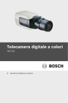
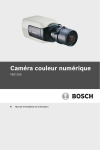
Digital Color Camera
VBC-255
en
Installation and Operation manual
Digital Color Camera
Table of Contents | en
3
Table of Contents
1
Safety
5
1.1
Safety precautions
5
1.2
Important safety instructions
6
1.3
Important notices
7
1.4
FCC & ICES compliance
8
1.5
UL certification
9
1.6
Bosch notices
10
2
Introduction
11
2.1
Features
11
2.2
Unpacking
11
3
Connections
12
3.1
Power connection
12
3.1.1
Low voltage cameras
12
3.1.2
High voltage cameras
13
3.2
Video connection
13
3.2.1
Composite video signal
13
3.2.2
Y/C output video signal
14
3.3
Lens mounting
15
3.4
Back focus adjustment
16
3.5
Mounting the camera
18
4
Configuration
19
4.1
Menus
19
4.1.1
Top level menus
19
4.1.2
Menu navigation
20
4.2
Main menu structure
21
4.2.1
Shutter/AGC submenu
22
4.2.2
Color submenu
23
4.3
Install menu structure
24
4.3.1
Lens Wizard submenu
25
Bosch Security Systems
Installation and Operation manual
AM18-Q0603 | v1.0 | 2011.04
4
en | Table of Contents
Digital Color Camera
5
Technical Data
27
5.1
Specifications
27
AM18-Q0603 | v1.0 | 2011.04
Installation and Operation manual
Bosch Security Systems
Digital Color Camera
Safety | en
1
Safety
1.1
Safety precautions
5
DANGER!
High risk: This symbol indicates an imminently hazardous
situation such as "Dangerous Voltage" inside the product.
If not avoided, this will result in an electrical shock, serious
bodily injury, or death.
WARNING!
Medium risk: Indicates a potentially hazardous situation.
If not avoided, this could result in minor or moderate bodily
injury.
CAUTION!
Low risk: Indicates a potentially hazardous situation.
If not avoided, this could result in property damage or risk of
damage to the unit.
Bosch Security Systems
Installation and Operation manual
AM18-Q0603 | v1.0 | 2011.04
6
en | Safety
1.2
Digital Color Camera
Important safety instructions
Read, follow, and retain for future reference all of the following
safety instructions. Heed all warnings on the unit and in the
operating instructions before operating the unit.
1.
Cleaning - Generally, using a dry cloth for cleaning is
sufficient but a moist, fluff-free cloth or leather shammy
may also be used. Do not use liquid cleaners or aerosol
cleaners.
2.
Heat Sources - Do not install the unit near any heat
sources such as radiators, heaters, stoves, or other
equipment (including amplifiers) that produce heat.
3.
Water - Never spill liquid of any kind on the unit.
4.
Lightning - Take precautions to protect the unit from
power and lightning surges.
5.
Controls adjustment - Adjust only those controls specified
in the operating instructions. Improper adjustment of
other controls may cause damage to the unit.
6.
Power sources - Operate the unit only from the type of
power source indicated on the label.
7.
Servicing - Unless qualified, do not attempt to service this
unit yourself. Refer all servicing to qualified service
personnel.
8.
Replacement parts - Use only replacement parts specified
by the manufacturer.
9.
Installation - Install in accordance with the manufacturer's
instructions and in accordance with applicable local codes.
10. Attachments, changes or modifications - Only use
attachments/accessories specified by the manufacturer.
Any change or modification of the equipment, not
expressly approved by Bosch, could void the warranty or,
in the case of an authorization agreement, authority to
operate the equipment.
AM18-Q0603 | v1.0 | 2011.04
Installation and Operation manual
Bosch Security Systems
Digital Color Camera
1.3
Safety | en
7
Important notices
Disposal - Your Bosch product was developed and
manufactured with high-quality material and components that
can be recycled and reused. This symbol means that
electronic and electrical appliances, which have reached the
end of their working life, must be collected and disposed of
separately from household waste material. Separate collecting
systems are usually in place for disused electronic and
electrical products. Please dispose of these units at an
environmentally compatible recycling facility, per European
Directive 2002/96/EC
WARNING!
Power disconnect for high voltage versions: A unit has power
supplied whenever the power cord is inserted into the power
source. The power cord plug is the main power disconnect for
the unit. For pluggable equipment, install the socket outlet near
the equipment so it is easily accessible.
WARNING!
All-pole power switch: Incorporate an all-pole power switch,
with a contact separation of at least 3 mm in each pole, into the
electrical installation of the building.
Bosch Security Systems
Installation and Operation manual
AM18-Q0603 | v1.0 | 2011.04
8
en | Safety
1.4
Digital Color Camera
FCC & ICES compliance
FCC & ICES Information
(U.S.A. and Canadian Models Only)
This equipment has been tested and found to comply with the
limits for a Class B digital device, pursuant to part 15 of the
FCC Rules. These limits are designed to provide reasonable
protection against harmful interference in a residential
installation. This equipment generates, uses, and can radiate
radio frequency energy and, if not installed and used in
accordance with the instructions, may cause harmful
interference to radio communications. However, there is no
guarantee that interference will not occur in a particular
installation. If this equipment does cause harmful interference
to radio or television reception, which can be determined by
turning the equipment off and on, the user is encouraged to try
to correct the interference by one or more of the following
measures:
–
reorient or relocate the receiving antenna;
–
increase the separation between the equipment and
receiver;
–
connect the equipment into an outlet on a circuit different
from that to which the receiver is connected;
–
consult the dealer or an experienced radio/TV technician
for help.
Intentional or unintentional modifications, not expressly
approved by the party responsible for compliance, shall not be
made. Any such modifications could void the user's authority to
operate the equipment. If necessary, the user should consult
the dealer or an experienced radio/television technician for
corrective action.
The user may find the following booklet, prepared by the
Federal Communications Commission, helpful: How to Identify
and Resolve Radio-TV Interference Problems. This booklet is
available from the U.S. Government Printing Office,
Washington, DC 20402, Stock No. 004-000-00345-4.
AM18-Q0603 | v1.0 | 2011.04
Installation and Operation manual
Bosch Security Systems
Digital Color Camera
1.5
Safety | en
9
UL certification
Disclaimer
Underwriter Laboratories Inc. ("UL") has not tested the
performance or reliability of the security or signaling aspects of
this product. UL has only tested fire, shock and/or casualty
hazards as outlined in UL's Standard(s) for Safety for Closed
Circuit Television Equipment, UL 2044. UL Certification does not
cover the performance or reliability of the security or signaling
aspects of this product.
UL MAKES NO REPRESENTATIONS, WARRANTIES, OR
CERTIFICATIONS WHATSOEVER REGARDING THE
PERFORMANCE OR RELIABILITY OF ANY SECURITY OR
SIGNALING RELATED FUNCTIONS OF THIS PRODUCT.
Disclaimer
Underwriter Laboratories Inc. ("UL") has not tested the
performance or reliability of the security or signaling aspects of
this product. UL has only tested fire, shock and/or casualty
hazards as outlined in UL's Standard(s) for Safety for Information
Technology Equipment, UL 60950-1. UL Certification does not
cover the performance or reliability of the security or signaling
aspects of this product.
UL MAKES NO REPRESENTATIONS, WARRANTIES, OR
CERTIFICATIONS WHATSOEVER REGARDING THE
PERFORMANCE OR RELIABILITY OF ANY SECURITY OR
SIGNALING-RELATED FUNCTIONS OF THIS PRODUCT.
Bosch Security Systems
Installation and Operation manual
AM18-Q0603 | v1.0 | 2011.04
10
en | Safety
1.6
Digital Color Camera
Bosch notices
Copyright
This manual is the intellectual property of Bosch Security
Systems and is protected by copyright. All rights reserved.
Trademarks
All hardware and software product names used in this
document are likely to be registered trademarks and must be
treated accordingly.
Note:
This manual has been compiled with great care and the
information it contains has been thoroughly verified. The text
was complete and correct at the time of printing. The ongoing
development of the products may mean that the content of the
user guide can change without notice. Bosch Security Systems
accepts no liability for damage resulting directly or indirectly
from faults, incompleteness or discrepancies between the user
guide and the product described.
More information
For more information please contact the nearest Bosch Security
Systems location or visit www.boschsecurity.com
AM18-Q0603 | v1.0 | 2011.04
Installation and Operation manual
Bosch Security Systems
Digital Color Camera
Introduction | en
2
Introduction
2.1
Features
11
The VBC-255 is a professional surveillance color camera that
incorporates 10-bit digital signal processing. The camera is easy
to install and ready to use, and offers good quality picture
performance.
Features include:
2.2
–
1/3-inch format CCD imager
–
Backlight compensation
–
Lens autodetection
–
Lens wizard for easy backfocus
Unpacking
Unpack carefully and handle the equipment with care.
The packaging contains:
–
Digital color camera
–
CCD protection cap (mounted on camera)
–
Spare lens connector (male)
–
These instructions
If equipment has been damaged during shipment, repack it in
the original packaging and notify the shipping agent or supplier.
WARNING!
Installation should only be performed by qualified service
personnel in accordance with the National Electrical Code or
applicable local codes.
CAUTION!
The camera module is a sensitive device and must be handled
carefully.
Bosch Security Systems
Installation and Operation manual
AM18-Q0603 | v1.0 | 2011.04
12
en | Connections
3
Digital Color Camera
Connections
CAUTION!
Before proceeding, disconnect the power from the power
supply cable. Ensure that the voltage of the unit matches the
voltage and type of the power supply being used.
3.1
Power connection
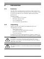
3.1.1
Low voltage cameras
VIDEO
12 VDC
24 VAC
10 mm
Figure 3.1
Low voltage power connection
Connect power from a 24 VAC or 12 VDC class 2 power supply
as follows:
–
Use AWG16 to 22 stranded wire; cut back 10 mm (0.4 in)
of insulation.
–
Push in the tabs and insert the wires.
Note
These connections are not polarity sensitive.
AM18-Q0603 | v1.0 | 2011.04
Installation and Operation manual
Bosch Security Systems
Digital Color Camera
3.1.2
Connections | en
13
High voltage cameras
VIDEO
Figure 3.2
High voltage power connection
Connect the power cable of a high voltage camera to a 230 VAC
power supply outlet.
3.2
Video connection
3.2.1
Composite video signal
VIDEO
Video BNC
Figure 3.3
Composite BNC connector
For a composite video output signal, connect the video coax
cable to the BNC connector of the camera.
Bosch Security Systems
Installation and Operation manual
AM18-Q0603 | v1.0 | 2011.04
14
en | Connections
3.2.2
Digital Color Camera
Y/C output video signal
Figure 3.4
Y/C connector
For a Y/C video output signal, connect the Y/C video cable to
the Y/C connector of the camera.
AM18-Q0603 | v1.0 | 2011.04
Installation and Operation manual
Bosch Security Systems
Digital Color Camera
3.3
Connections | en
15
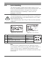
Lens mounting
The camera accepts C-mount and CS-mount lenses. DC-iris
lenses are recommended for the best picture performance. The
camera automatically detects the type of lens used and
optimizes performance accordingly. A spare male lens
connector is provided.
CAUTION!
To avoid damaging the CCD sensor when using a C-mount lens,
turn the green back-focus ring counterclockwise until it stops
before mounting the lens.
Lenses weighing more than 0.5 kg (1.1lbs) must be separately
supported.
Bosch
Bosch
Figure 3.5 Mounting a lens
Figure 3.6 Lens connector
Pin
Video iris lens
DC iris lens
1
Supply (11.5V ±0.5, 50mA max.)
Damp -
2
Not used
Damp +
3
Video signal 1Vpp 1kOhm
Drive +
4
Ground
Drive -
Note
If a short circuit is detected on the lens connector, the onscreen display (OSD) failure message LENS SHORT CIRCUIT is
shown. The lens circuit is automatically disabled to avoid
internal damage. Remove the lens connector and check the pin
connections.
Bosch Security Systems
Installation and Operation manual
AM18-Q0603 | v1.0 | 2011.04
16
en | Connections
3.4
Digital Color Camera
Back focus adjustment
To optimize picture sharpness in both bright and low-level
lighting, adjust the back focus. Use the camera's unique Lens
Wizard. This ensures that the object of interest always remains
in focus, even when focusing at the maximum lens iris opening.
–
When back focusing zoom lenses, ensure the object of
interest remains in focus throughout the entire zoom range
of the lens.
To adjust back focus:
1.
Open the slide door panel at the side of the camera.
Bos
ch
1.
Unlock the back focus locking button.
2.
Press and hold the center key for more than 1.5 seconds
until the Install menu appears.
3.
Select Wizard and move cursor to the Set Back Focus
Now item.
4.
Turn the back focus adjustment as required.
Bosch
5.
Lock the back focus locking button.
AM18-Q0603 | v1.0 | 2011.04
Installation and Operation manual
Bosch Security Systems
Digital Color Camera
Connections | en
17
Bosch
6.
Press and hold the center key for more than 1 second until
all the menus disappear.
7.
Close the side door panel.
Note:
To back focus a zoom lens, see the zoom lens installation guide.
Bosch Security Systems
Installation and Operation manual
AM18-Q0603 | v1.0 | 2011.04
18
en | Connections
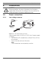
3.5
Digital Color Camera
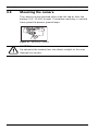
Mounting the camera
The camera can be mounted either from the top or from the
bottom (1/4" 20 UNC thread). The bottom mounting is isolated
from ground to prevent ground loops.
Figure 3.7
Mounting a camera
CAUTION!
Do not point the camera/lens into direct sunlight as this may
damage the sensors.
AM18-Q0603 | v1.0 | 2011.04
Installation and Operation manual
Bosch Security Systems
Digital Color Camera
4
Configuration | en
19
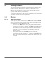
Configuration
The camera normally provides an optimal picture without the
need for further adjustments. However, advanced set-up
options are available in a menu system for getting the best
results under special circumstances.
The camera implements the changes immediately so that before
and after settings are easily compared.
4.1
4.1.1
Menus
Top level menus
There are two upper level menus: a Main menu and an Install
menu. The menus have functions that can be selected directly
or submenus for more detailed set-up.
–
To access the Main menu, press the menu/select button
(center) for less than 1 second. The Main menu appears on
the monitor. Select and set-up the picture enhancement
functions. If not satisfied with the changes, recall the
default values.
–
The camera also has an Install menu in which the
installation settings can be set. To access the Install menu,
press the menu/select button (center) for longer than 1.5
seconds.
Bosch Security Systems
Installation and Operation manual
AM18-Q0603 | v1.0 | 2011.04
20
en | Configuration
4.1.2
Digital Color Camera
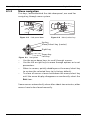
Menu navigation
Five keys, located behind the side door panel, are used for
navigating through menu system.
Bos
ch
Bosch
Figure 4.1 Side panel door
Figure 4.2 Menu/select key
Up key
Menu/Select key (center)
Right key
Figure 4.3
Navigation
Down key
Left key
–
Use the up or down keys to scroll through a menu.
–
Use the left or right keys to move through options or to set
parameters.
–
When in a menu, quickly double-press the menu/select key
–
To close all menus at once hold down the menu/select key
to restore the selected item to its factory default.
until the menu display disappears or continually select the
Exit item.
Some menus automatically close after about two minutes; other
menus have to be closed manually.
AM18-Q0603 | v1.0 | 2011.04
Installation and Operation manual
Bosch Security Systems
Digital Color Camera
4.2
Configuration | en
21
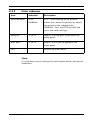
Main menu structure
Item
Selection
Description
Level
-15 to +15
Video level control: A positive value is
more useful for low-light conditions; a
negative value is more useful for very
bright conditions.
Shut/AGC
Submenu
Picture enhancement and performance
BLC
On, Off,
Set to On to enable Back Light
Compensation (BLC). When On, the
level is optimized at the center of the
screen. Parts outside the center may
be under- or over-exposed (this is
normal).
Color*
ATW
White balance and color rendition (not
AWB hold
available in NightSense mode)
Submenu
Sync
Internal
Internal - for free running camera
Line lock
operation.
Line lock - to lock to the AC power
supply
V-Phase
0 to 358°
Adjusts the vertical phase
(only available if sync = line lock).
Exit
Exit the menu
*Note:
If the camera is in NightSense mode, the color settings and
color menu are not accessible. NightSense must be Off to make
color adjustments.
Bosch Security Systems
Installation and Operation manual
AM18-Q0603 | v1.0 | 2011.04
22
en | Configuration
4.2.1
Digital Color Camera
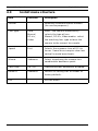
Shutter/AGC submenu
Item
Selection
Description
Shutter
AES, FL
AES (auto-shutter) - the camera
automatically sets the optimum shutter
speed.
FL - flickerless mode avoids
interference from light sources
(recommended for video-iris or DC-iris
lenses only).
AGC
On, Off
On - the camera automatically sets the
gain to the lowest possible value
needed to maintain a good picture.
Off - sets AGC off.
Autoblack
On, Off
Autoblack On automatically increases
the visibility of details even when
scene contrast is less than full-range
due to mist, fog, etc.
NightSense
Auto,
Nightsense extends the low-
Forced,
lightperformance of the camera. AUTO
Off
mode, the camera automatically inches
to monochrome in low-light conditions.
Forced mode, the picture remains a
high-sensitivity monochrome
image.Some active noise or white
spots may appear in the picture.
EXIT
AM18-Q0603 | v1.0 | 2011.04
Returns to main menu.
Installation and Operation manual
Bosch Security Systems
Digital Color Camera
4.2.2
Configuration | en
23
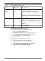
Color submenu
Item
Selection
Description
White balance
ATW,
ATW - Auto tracking white balance
AWBhold
allows the camera to constantly adjust
for optimal color reproduction.
AWBhold - Puts the ATW on hold and
saves the color settings.
Red gain*
-5 to +5
Adjusts the Red gain to optimize the
white point.
Blue gain*
-5 to +5
Adjusts the B gain to optimize the
white point.
EXIT
Returns to main menu.
*Note:
It is only necessary to change the white point offsets for special
conditions.
Bosch Security Systems
Installation and Operation manual
AM18-Q0603 | v1.0 | 2011.04
24
en | Configuration
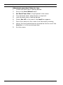
4.3
Item
Digital Color Camera
Install menu structure
Selection
Version
Description
Read-only firmware release number
(for service purposes).
Lens type
Auto,
Auto: - the camera automatically
Manual,
selects the type of lens.
DC-iris,
Manual, DC-iris, Video modes: select
Video
the matching lens type to force the
camera to the correct lens mode.
Speed
Fast
Selects the response time of DC-iris
lenses. Some lenses require slow lens
control to avoid overshoots.
Wizard
Submenu
Select to optimize the camera-lens
combination backfocus point.
Coax Com
On, Off
Communications enabled or disabled.
Defaults
Submenu
Returns all settings for all modes to
factory defaults
Exit
AM18-Q0603 | v1.0 | 2011.04
Exit the menu
Installation and Operation manual
Bosch Security Systems
Digital Color Camera
4.3.1
Configuration | en
25
Lens Wizard submenu
Item
Selection
Description
Set Backfocus
Select to fully open the iris. Follow the
now
instructions below for setting the
backfocus for your particular lens type.
After focusing the object of interest
remains in focus under bright and low
light conditions.
Set LVL
Only for video-iris lenses.
Adjust the level control on the lens to
center the level detector indicator (see
below).
EXIT
Exit the menu
Adjustment procedure DC-iris Lens
1.
Unlock the back focus locking button.
2.
Access the Lens Wizard menu.
3.
Set Back Focus Now is highlighted in the menu.
4.
Turn the back focus adjustment as required.
5.
Lock the back focus locking button.
6.
Exit the menu.
Adjustment procedure Manual-iris Lens
1.
Unlock the back focus locking button.
2.
Adjust the lens to the maximum lens opening.
3.
Turn the back focus adjustment as required.
4.
Lock the back focus locking button.
5.
Adjust lens opening to suit scene.
Bosch Security Systems
Installation and Operation manual
AM18-Q0603 | v1.0 | 2011.04
26
en | Configuration
Digital Color Camera
Adjustment procedure Video-iris Lens
1.
Unlock the back focus locking button.
2.
Access the Lens Wizard menu.
3.
Set Back Focus Now is highlighted in the menu.
4.
Turn the back focus adjustment as required.
5.
Lock the back focus locking button.
6.
Select Set LVL in the menu; the Level bar appears.
7.
Point the camera at the scene it will be mostly viewing.
8.
Adjust the level potentiometer located on the lens until the
Level bar is in the central position.
9.
Exit the menu.
AM18-Q0603 | v1.0 | 2011.04
Installation and Operation manual
Bosch Security Systems
Digital Color Camera
Technical Data | en
5
Technical Data
5.1
Specifications
Type number
VBC255/11
VBC255/51
Rated supply
+12 VDC
230 VAC 50 Hz
voltage
24 VAC (50 Hz)
27
All versions
Imager
1/3-inch Interline CCD
Resolution
540 TVL
Standard
PAL
Active pixels
752 x 582
Minimum
<0.65 lux
illumination
<0.26 lux with NightSense
SNR
> 50 dB
Video output
1 Vpp, 75 Ohm
Synchroniza-
Internal, Line Lock selectable
tion
Shutter
AES (1/50 to 1/125000]) automatic, flickerless, Off
selectable
AGC
AGC On (0-21 dB) or Off (0 dB) selectable
Back Light
One area, center-weighted
Compensation
(BLC)
White Balance
ATW, AWBhold (2500 to 9000K)
Lens mount
C and CScompatible
ALC lens
Video or DC iris auto detect
Power
<4 W
consumption
Dimensions
58 x 66 x 122 mm (2.28 x 2.60 x 4.80 in) without lens
(H x W L)
Weight
Bosch Security Systems
450 g (0.99 lb) without lens
Installation and Operation manual
AM18-Q0603 | v1.0 | 2011.04
28
en | Technical Data
Tripod mount
Digital Color Camera
Two 1/4" 20 UNC - isolated (bottom) and non-isolated
(top)
Operating
-20 °C to +50 °C (-4 °F to +122 °F)
temperature
Controls
OSD with softkey operation
AM18-Q0603 | v1.0 | 2011.04
Installation and Operation manual
Bosch Security Systems
Bosch Security Systems
www.boschsecurity.com
© Bosch Security Systems, 2011