1
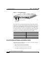
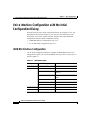
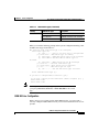
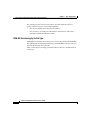
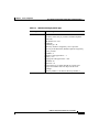
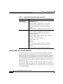
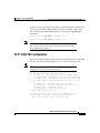
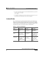
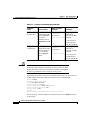
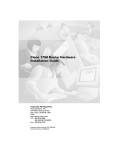
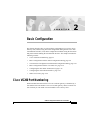
C H A P T E R
2
Basic Configuration
This chapter describes how to perform basic configuration of your Cisco Voice
Gateway 200 (VG200) using the initial configuration dialog and the Cisco IOS
command line interface (CLI). Basic configuration includes setting the host name
and password and enabling the Fast Ethernet interface. This chapter includes the
following sections:
•
Cisco VG200 Port Numbering, page 2-1
•
Basic Configuration with the Initial Configuration Dialog, page 2-4
•
Voice Interface Configuration with the Intial Configuration Dialog, page 2-10
•
Basic Configuration with the Cisco IOS CLI, page 2-16
•
Configuring the Host Name and Password, page 2-19
•
Configuring the Fast Ethernet Interface, page 2-22
•
Where to Go Next, page 2-24
Cisco VG200 Port Numbering
Each individual network interface on a Cisco VG200 gateway is identified by a
slot number and a unit number. The Cisco VG200 gateway chassis contains one
slot in which you can install a network module. This is always slot 1.
Software Configuration Guide for the Cisco VG200
78-10322-02
2-1
Chapter 2
Basic Configuration
Cisco VG200 Port Numbering
Figure 2-1
Cisco VG200 Analog Ports
SERIAL 1
100-240V– 1A
50/60 Hz 47 W
SERIAL 1
WIC
CONN 2A/S
CONN
SEE MANUAL BEFORE INSTALLATION
SERIAL 0
WIC
CONN 2A/S
CONN
CONN
SEE MANUAL BEFORE INSTALLATION
WIC
CONN 2A/S
SERIAL 0
CONN
SEE MANUAL BEFORE INSTALLATION
CONN
WIC
2T
SEE MANUAL BEFORE INSTALLATION
W1
W0
LINK ETHERNET 0 ACT
1/1/0
AUX
1/0/1
1/0/0
38135
1/1/1
CONSOLE
Slot=1/VIC=0/Port=0
FXS/FX0 Ports
Slot 1 contains the voice network module, which can support analog or digital
connections to the Public Switched Telephone Network (PSTN), and which can
hold one or two voice interface cards (VIC). Each VIC, in turn, can provide one
or two ports. During configuration, you refer to each voice port by its numeric
order, starting with zero. Note that the physical ports on a Cisco VG200 gateway
are numbered from right to left, with 1/0/0 identifying the right port on the right
VIC, while 1/1/1 is the left port on the left VIC. The following table lists the
identifiers for each port that can be configured on the Cisco VG200.
Interface type
Port numbers (from right to left)
Analog Voice/Fax (FXS, FX0, E&M)
1/0/0, 1/0/1, 1/1/0, 1/1/1
BRI Voice/Fax
1/0/0, 1/1/0
E1/T1 Voice Trunk
1/0, 1/1
Channelized E1/T1 ISDN PRI
1/0, 1/1
Voice/Fax Network Modules and Interface Cards
The analog voice network module and voice interface cards available at this time
for the Cisco VG200 are as follows:
•
NM1V One-Slot Voice/Fax Network Module
•
NM2V Two-Slot Voice/Fax Network Module
•
VIC-1FXS One-Port Voice/Fax Interface Card—FXS
•
VIC-2FXS Two-Port Voice/Fax Interface Card—FXS
Software Configuration Guide for the Cisco VG200
2-2
78-10322-02
Chapter 2
Basic Configuration
Cisco VG200 Port Numbering
•
VIC-1FXO One-Port Voice/Fax Interface Card—FXO
•
VIC-2FXO One-Port Voice/Fax Interface Card—FXO
•
VIC-1E/M One-Port Voice/Fax Interface Card—E&M
•
VIC-2E/M Two-Port Voice/Fax Interface Card—E&M
•
VIC-1BRI-S/T-TE One-Port BRI Voice/Fax Interface Card
•
VIC-2BRI-S/T-TE Two-Port BRI Voice/Fax Interface Card
Digital T1/E1 Voice Trunk Modules and Interface Cards
The T1/E1 voice trunk modules and voice interface cards available at this time for
the Cisco VG200 are as follows:
•
VWIC-1MFT-T1 One-Port RJ-48 Multiflex Trunk—T1
•
VWIC-2MFT-T1 Two-Port RJ-48 Multiflex Trunk—T1
•
VWIC-2MFT-T1-D1 Two-Port RJ-48 Multiflex Trunk—T1 with Drop &
Insert support
•
VWIC-1MFT-E1 One-Port RJ-48 Multiflex Trunk—E1
•
VWIC-2MFT-E1 Two-Port RJ-48 Multiflex Trunk—E1
•
VWIC-2MFT-E1-D1 Two-Port RJ-48 Multiflex Trunk—E1 with Drop &
Insert support
•
NM-HDV-1T1-24 Single-Port 24-Channel T1 Voice/Fax Network Module
•
NM-HDV-1T1-24E Single-Port 24-Enhanced Channel T1 Voice/Fax
Network Module
•
NM-HDV-2T1-48 Single-Port 48-Channel T1 Voice/Fax Network Module
•
NM-HDV-1E1-30 Single-Port 30-Channel E1 Voice/Fax Network Module
•
NM-HDV-1E1-30E Single-Port 30-Enhanced Channel E1 Voice/Fax
Network Module
•
NM-HDV-2E1-60 Single-Port 60-Channel E1 Voice/Fax Network Module
Software Configuration Guide for the Cisco VG200
78-10322-02
2-3
Chapter 2
Basic Configuration
Basic Configuration with the Initial Configuration Dialog
Channelized E1/T1 ISDN PRI Network Modules
The T1/E1 channelized T1 ISDN PRI network modules available at this time for
the Cisco VG200 are as follows:
•
NM-1CT1 1-Port Channelized T1/ISDN PRI Network Module
•
NM-1CT1-CSU 1-Port Channelized T1/ISDN PRI CSU Network Module
•
NM-2CT1 2-Port Channelized T1/ISDN PRI Network Module
•
NM-2CT1-CSU 2-Port Channelized T1/ISDN PRI CSU Network Module
•
NM-1CE1B 1-Port Channelized E1/ISDN PRI Balanced Network Module
•
NM-1CE1U 1-Port Channelized E1/ISDN PRI Unbalanced Network Module
•
NM-2CE1B 2-Port Channelized E1/ISDN PRI Balanced Network Module
•
NM-2CE1U 2-Port Channelized E1/ISDN PRI Unbalanced Network Module
Basic Configuration with the Initial Configuration
Dialog
The initial configuration dialog provides prompts to help you configure basic
information about your Cisco VG200 gateway. The following sections describe
the way to use the intial configuration dialog to configure the following
information:
•
Host name
•
Passwords
•
Ethernet interface configuration
The initial configuration dialog displays these prompts in your PC terminal
emulation program window. Before running the initial configuration dialog,
configure your PC terminal emulation program for 9600 baud, 8 data bits, no
parity, and 1 stop bit.
You can also complete the following configuration steps by entering the
appropriate command-line interface(CLI) commands, as described in the “Basic
Configuration with the Cisco IOS CLI” section on page 2-16. Perform the
following steps to complete basic configuration of a Cisco VG200 gateway, using
the initial configuration dialog:
Software Configuration Guide for the Cisco VG200
2-4
78-10322-02
Chapter 2
Basic Configuration
Basic Configuration with the Initial Configuration Dialog
Step 1
Power on the gateway. The power switch is on the rear panel of the gateway, at the
lower right corner, near the power cord.
Messages will begin to appear in your terminal emulation program window.
Caution
Do not press any keys on the keyboard until the messages stop. Any
keys pressed during this time are interpreted as the first command
entered when the messages stop, which might cause the gateway to
power off and start over. It takes a few minutes for the messages to
stop.
Note
If you make a mistake while using the initial configuration
dialog, you can exit and run the facility again. Press Ctrl-c,
and enter setup at the enable mode prompt (VG200 #).
Software Configuration Guide for the Cisco VG200
78-10322-02
2-5
Chapter 2
Basic Configuration
Basic Configuration with the Initial Configuration Dialog
The messages look similar to the following:
######################################################################
######################################################################
############################################################## [OK]
Restricted Rights Legend
Use, duplication, or disclosure by the Government is
subject to restrictions as set forth in subparagraph
(c) of the Commercial Computer Software - Restricted
Rights clause at FAR sec. 52.227-19 and subparagraph
(c) (1) (ii) of the Rights in Technical Data and Computer
Software clause at DFARS sec. 252.227-7013.
Cisco Systems, Inc.
170 West Tasman Drive
San Jose, California 95134-1706
Cisco Internetwork Operating System Software
IOS (tm) VG200 Software (VG200-I6S-M), Experimental Version
12.0(20000117:081249) [sfry-viola_eft2 116]
Copyright (c) 1986-2000 by Cisco Systems, Inc.
Compiled Fri 28-Jan-00 22:18 by sfry
Image text-base: 0x80008088, data-base: 0x8066E970
cisco VG200 (MPC860) processor (revision 0x102) with 22528K/2048K
bytes of memory.
Processor board ID JAB034202S3 (0)
M860 processor: part number 0, mask 49
1 FastEthernet/IEEE 802.3 interface(s)
2 Voice FXS interface(s)
32K bytes of non-volatile configuration memory.
8192K bytes of processor board System flash (Read/Write)
Step 2
When the following message appears, enter yes to begin the initial configuration
dialog:
Would you like to enter the initial configuration dialog? [yes/no]:
Note
If you enter n (for no) in response to this message, you are
prompted to terminate the initial configuration dialog. If you
choose to terminate, you enter the Cisco IOS software
command-line interface without running the configuration
dialog.
Software Configuration Guide for the Cisco VG200
2-6
78-10322-02
Chapter 2
Basic Configuration
Basic Configuration with the Initial Configuration Dialog
Step 3
When the following message appears, enter yes to perform basic management
setup:
Would you like to enter basic management setup? [yes/no]: yes
Step 4
Enter the host name for the VG200, as in the following example:
Configuring global parameters:
Enter host name [Router]: VG200
You must make sure the same entry is used when configuring the Cisco VG200
gateway on Cisco CallManager.
Step 5
When you see the following prompt, enter an enable secret password:
Enter enable secret: xxxx
The enable secret is a password used to protect access to privileged
EXEC and configuration modes. This password, after entered, becomes
encrypted in the configuration.
Step 6
When you see the following prompt, enter an enable password that is different
from the enable secret password.
Enter enable password: guessme
The enable password is used when you do not specify an enable secret
password, with some older software versions, and some boot images.
Note
Step 7
The enable password is not encrypted (less secure) and can
be seen when viewing the configuration.
Enter the virtual terminal password, which prevents unauthenticated access to the
gateway through ports other than the console port.
Enter virtual terminal password: guessagain
The virtual terminal password is used to protect access to the gateway
over a network interface.
Software Configuration Guide for the Cisco VG200
78-10322-02
2-7
Chapter 2
Basic Configuration
Basic Configuration with the Initial Configuration Dialog
Step 8
When you see the following prompt, identify the Fast Ethernet interface, which
you must configure to use the VG200.
Current interface summary
Any interface listed with OK? value "NO" does not have a valid
configuration
Interface
FastEthernet0/0
IP-Address
unassigned
OK? Method Status
NO unset up
Protocol
up
Enter interface name used to connect to the
management network from the above interface summary: FastEthernet0/0
d dialing? [no]:
Step 9
Configure the Fast Ethernet interface.
When you see the following prompts, enter the selections shown below, and then
enter the IP address for the gateway on the Ethernet LAN.
Configuring interface parameters:
Do you want to configure FastEthernet0/0 interface [yes]:
Use the 100 Base-TX (RJ-45) connector? [yes]:
Operate in full-duplex mode? [no]:
Configure IP on this interface? [no]: yes
IP addresss for this interface: 192.168.100.1
Software Configuration Guide for the Cisco VG200
2-8
78-10322-02
Chapter 2
Basic Configuration
Basic Configuration with the Initial Configuration Dialog
Step 10
Save the configuration, as follows:
The following configuration command script was created:
hostname vg200
enable secret 5 $1$6F..$Lc8rqF6Nnos33ARvs9Uu7/
enable password cisco
line vty 0 4
password lab
snmp-server community public
!
no ip routing
!
interface FastEthernet0/0
no shutdown
full-duplex
ip address 192.168.100.1 255.255.255.0
!
end
:
Use this configuration? [yes/no]: yes
If you answer no, the configuration information you entered is not saved, and the
system displays the gateway enable prompt (VG200 #). You can then enter setup
to return to the initial configuration dialog.
If you answer yes, the configuration is saved and you are returned to the EXEC
prompt (for example, VG200>).
Building configuration...
Use the enabled mode 'configure' command to modify this configuration.
Step 11
When the messages stop displaying on your screen, press Return to get the EXEC
prompt (for example, VG200>).
Press RETURN to get started!
%LINK-3-UPDOWN: Interface FastEthernet0/0, changed state to up
...
The VG200> prompt indicates that you are now at the CLI.
Software Configuration Guide for the Cisco VG200
78-10322-02
2-9
Chapter 2
Basic Configuration
Voice Interface Configuration with the Intial Configuration Dialog
Voice Interface Configuration with the Intial
Configuration Dialog
From this point on in the initial configuration dialog, the prompts you see vary
depending on the network modules in your gateway. The following sections
describe the steps for the optional interface modules that require additional
configuration using the intitial configuration dialog.
•
ISDN BRI Interface Configuration, page 2-10
•
E1/T1 ISDN PRI Configuration, page 2-15
ISDN BRI Interface Configuration
Use the initial configuration dialog to configure an ISDN BRI interface. This
configuration requires you to enter the ISDN switch type. These switch types are
shown in Table 2-1.
Table 2-1
ISDN Switch Types
Country
ISDN Switch Type
DescrIption
Australia
basic-ts013
Australian TS013 switches
Europe
basic-1tr6
German 1TR6 ISDN switches
basic-nwnet3
Norwegian NET3 ISDN switches
(phase 1)
basic-net3
NET3 ISDN switches (UK and
others)
basic-net5
NET5 switches (UK and others)
vn2
French VN2 ISDN switches
vn3
French VN3 ISDN switches
Japan
ntt
Japanese NTT ISDN switches
New Zealand
basic-nznet3
New Zealand NET3 switches
Software Configuration Guide for the Cisco VG200
2-10
78-10322-02
Chapter 2
Basic Configuration
Voice Interface Configuration with the Intial Configuration Dialog
Table 2-1
ISDN Switch Types (continued)
Country
ISDN Switch Type
North America basic-5ess
DescrIption
AT&T basic rate switches
basic-dms100
NT DMS-100 basic rate switches
basic-ni1
National ISDN-1 switches
When you reach the following prompt on the System Configuration Dialog, enter
an ISDN switch type from Table 2-1:
BRI interface needs isdn switch-type to be configured
Valid switch types are:
[0] none..........Only if you don't want to configure BRI.
[1] basic-1tr6....1TR6 switch type for Germany
[2] basic-5ess....AT&T 5ESS switch type for the US/Canada
[3] basic-dms100..Northern DMS-100 switch type for
US/Canada
[4] basic-net3....NET3 switch type for UK and Europe
[5] basic-ni......National ISDN switch type
[6] basic-ts013...TS013 switch type for Australia
[7] ntt...........NTT switch type for Japan
[8] vn3...........VN3 and VN4 switch types for France
Choose ISDN BRI Switch Type [2]:
Do you want to configure BRI0/0 interface? [yes]:
Do you have a service profile identifiers (SPIDs) assigned? [no]: y
Enter SPID1: 12345
Enter SPID2: 12345
Note
The setup command facility only prompts for the SPID number if
you specify basic-5ess, basic-ni1, or basic-dms100 for the switch
type.
ISDN BRI Line Configuration
Before using a Cisco VG200 with an ISDN BRI interface, you must order a
correctly configured ISDN BRI line from your local telecommunications service
provider.
Software Configuration Guide for the Cisco VG200
78-10322-02
2-11
Chapter 2
Basic Configuration
Voice Interface Configuration with the Intial Configuration Dialog
The ordering process varies from provider to provider and from country to
country. However, here are some general guidelines:
•
Ask for two channels to be called by one number.
•
Ask for delivery of calling line identification, also known as caller ID or
Automatic Number Identification (ANI).
ISDN BRI Provisioning by Switch Type
ISDN BRI provisioning refers to the types of services provided by the ISDN BRI
line. Although provisioning is performed by your ISDN BRI service provider, you
must tell the provider what you want.
Table 2-2 lists the provisioning you should order for the Cisco VG200 based on
switch type.
Software Configuration Guide for the Cisco VG200
2-12
78-10322-02
Chapter 2
Basic Configuration
Voice Interface Configuration with the Intial Configuration Dialog
Table 2-2
ISDN Provisioning by Switch Type
Switch Type
Provisioning
5ESS Custom BRI
For voice
(Use these values only if you have an ISDN telephone
connected.)
2 B channels for voice
MultiPoint
Terminal type = D
2 directory numbers assigned by service provider
2 service profile identifiers (SPIDs) required, assigned by
service provider
MTERM = 2
Number of call appearances = 1
Display = No
Ringing/idle call appearances = idle
Autohold= no
Onetouch = no
Request delivery of calling line ID on Centrex lines
Set speed for ISDN calls to 56 kbps outside local
exchange
Directory number 1 can hunt to directory number 2
Software Configuration Guide for the Cisco VG200
78-10322-02
2-13
Chapter 2
Basic Configuration
Voice Interface Configuration with the Intial Configuration Dialog
Table 2-2
ISDN Provisioning by Switch Type (continued)
Switch Type
Provisioning
5ESS National
ISDN (NI-1) BRI
Terminal type = A
2 B channels for voice
2 directory numbers assigned by service provider
2 SPIDs required; assigned by service provider
Set speed for ISDN calls to 56 kbps outside local
exchange
Directory number 1 can hunt to directory number 2
DMS-100 BRI
2 B channels for voice
2 directory numbers assigned by service provider
2 SPIDs required; assigned by service provider
Functional signaling
Dynamic terminal endpoint identifier (TEI) assignment
Maximum number of keys = 64
Release key = no, or key number = no
Ringing indicator = no
EKTS = no
PVC = 2
Request delivery of calling line ID on Centrex lines
Set speed for ISDN calls to 56 kbps outside local
exchange
Directory number 1 can hunt to directory number 2
Defining ISDN Service Profile Identifiers
Some service providers assign service profile identifiers (SPIDs) to define the
services subscribed to by an ISDN device. If your service provider requires
SPIDs, your ISDN device cannot place or receive calls until it sends a valid SPID
to the service provider when initializing the connection. A SPID is usually a
seven-digit telephone number plus some optional numbers, but service providers
may use different numbering schemes. SPIDs have significance at the local access
ISDN interface only.
Currently, only DMS-100 and NI-1 switch types require SPIDs. Two SPIDs are
assigned for the DMS-100 switch type, one for each B channel. The AT&T 5ESS
switch type may support SPIDs, but Cisco recommends that you set up that ISDN
service without SPIDs.
Software Configuration Guide for the Cisco VG200
2-14
78-10322-02
Chapter 2
Basic Configuration
Voice Interface Configuration with the Intial Configuration Dialog
If your service provider assigns you SPIDs, you must define these SPIDs on the
Cisco VG200. To define SPIDs and the local directory number (LDN) on the
Cisco VG200 for both ISDN BRI B channels, use the following isdn spid
commands:
VG200(config-if)# isdn spid1 spid-number [ldn]
VG200(config-if)# isdn spid2 spid-number [ldn]
Note
Although the LDN is an optional parameter in the command, you
may need to enter it so the Cisco VG200 can answer calls made to
the second directory number.
E1/T1 ISDN PRI Configuration
This section contains a sample configuration for the channelized E1/T1 ISDN PRI
interface. Enter the values appropriate for your Cisco VG200 and network.
Note
The messages you see will vary depending on the hardware
configuration of your Cisco VG200 gateway.
The following ISDN switch types are available:
[0] none............If you do not want to configure ISDN
[1] primary-4ess....AT&T 4ESS switch type for US and Canada
[2] primary-5ess....AT&T 5ESS switch type for US and Canada
[3] primary-dms100..Northern Telecom switch type for US and
Canada
[4] primary-net5....European switch type for NET5
[5] primary-ni......National ISDN Switch type for the U.S
[6] primary-ntt.....Japan switch type
[7] primary-ts014...Australian switch type
Choose ISDN PRI Switch Type [2]:
Configuring controller T1 1/0 in pri or channelized mode
Do you want to configure this interface controller? [no]:
Will you be using PRI on this controller? [yes]:
Software Configuration Guide for the Cisco VG200
78-10322-02
2-15
Chapter 2
Basic Configuration
Basic Configuration with the Cisco IOS CLI
The following is an example of a E1/T1 PRI mode configuration using the setup
command facility:
The following framing types are available:
esf | sf
Enter the framing type [esf]:
The following linecode types are available:
ami | b8zs
Enter the line code type [b8zs]:
Enter number of time slots [24]:
Do you want to configure Serial1/0:23 interface? [yes]:
Basic Configuration with the Cisco IOS CLI
The Cisco VG200 runs the Cisco IOS Release 12.1(1)XE, which includes
specialized adaptations for Voice over IP (VoIP) and Media Gateway Control
Protocol (MGCP). If you are familiar with other versions of the Cisco IOS, you
will find configuring the Cisco VG200 gateway straightforward because you will
use the Cisco IOS CLI, with which you are familiar.
If you have never used the Cisco IOS CLI, you should still be able to perform the
configuration required using the instructions and examples provided in this guide.
To help get you started, this section provides a brief overview of some of the main
features of the CLI. For further information, refer to the Cisco IOS configuration
guides and command references for details about specific commands.
Getting Help
Use the question mark (?) and arrow keys to help you enter commands, as follows:
•
For a list of available commands, enter a question mark, for example:
VG200> ?
•
To complete a command, enter a few known characters followed by a question
mark (with no space), for example:
VG200> s?
Software Configuration Guide for the Cisco VG200
2-16
78-10322-02
Chapter 2
Basic Configuration
Basic Configuration with the Cisco IOS CLI
•
For a list of command variables, enter the command followed by a space and
a question mark, for example:
VG200> show ?
•
To redisplay a command you previously entered, press the up arrow key. You
can continue to press the up arrow key for more commands.
Command Modes
The Cisco IOS interface is divided into different modes. Each command mode
permits you to configure different components on your gateway. The commands
available at any given time depend on which mode you are currently in. Entering
a question mark (?) at the prompt displays a list of commands available for each
command mode. Table 2-1 lists the most common command modes.
Table 2-3
Common Command Modes
Command
Mode
Access Method
Gateway Prompt
Displayed
User EXEC
Log in.
hostname>
The default is
Exit Method
Use the logout
command.
router>
Privileged
EXEC
Global
configuration
From user EXEC
mode, enter the
enable command.
hostname#
The default is
router#
From the privileged hostname
EXEC mode, enter (config)#
The default is
the configure
terminal command. router (config)#
To exit to user
EXEC mode, use
the disable, exit, or
logout command.
To exit to privileged
EXEC mode, use
the exit or end
command, or press
Ctrl-Z.
Software Configuration Guide for the Cisco VG200
78-10322-02
2-17
Chapter 2
Basic Configuration
Basic Configuration with the Cisco IOS CLI
Table 2-3
Common Command Modes (continued)
Command
Mode
Interface
configuration
Dial-peer
configuration
Timesaver
Access Method
Gateway Prompt
Displayed
Exit Method
hostname
From the global
configuration mode, (config-if)#
enter the interface The default is
router (config-if)#
type number
command, such as
FastEthernet serial
1/0.
To exit to global
configuration
mode, use the exit
command.
hostname(configFrom the global
configuration mode, dial-peer)
The default is
enter the dial-peer
router
voice command,
(config-dial-peer)#
such as dial-peer
voice 1.
To exit to global
configuration
mode, use the exit
command.
To exit directly to
privileged EXEC
mode, press Ctrl-Z.
To exit directly to
privileged EXEC
mode, press Ctrl-Z.
Each command mode restricts you to a subset of commands. If you
are having trouble entering a command, check the prompt, and enter
the question mark (?) for a list of available commands. You might be
in the wrong command mode or using the wrong syntax.
In the following example, which uses the default prompt (router>), notice how the
prompt changes after each command to indicate a new command mode:
router> enable
Password: <enable password>
router#configure terminal
router(config-if)# line 0
router(config-line)# controller t1 1/0
router(config-controller)# exit
router(config)# exit
router#
%SYS-5-CONFIG_I: Configured from console by console
The last message is normal and does not indicate an error. Press Return to return
to the prompt.
Software Configuration Guide for the Cisco VG200
2-18
78-10322-02
Chapter 2
Basic Configuration
Configuring the Host Name and Password
Note
You can press Ctrl-Z in any mode to immediately return to
privileged EXEC mode (router#), instead of entering exit, which
returns you to the previous mode.
Disabling a Command or Feature
If you want to undo a command you entered or disable a feature, enter the
keyword no before most commands; for example, no mgcp.
Saving Configuration Changes
You need to enter the copy running-config startup-config command to save your
configuration changes to nonvolatile random-access memory (NVRAM), so the
changes are not lost if there is a system reload or power outage. For example:
router# copy running-config startup-config
Building configuration...
Note
It might take a minute or two to save the configuration to NVRAM.
After the configuration has been saved, the privileged EXEC mode
prompt (router#) reappears.
Configuring the Host Name and Password
Configuring a host name allows you to distinguish multiple Cisco gateways from
each other. Setting an encrypted password allows you to prevent unauthorized
configuration changes.
You might want to use CLI commands if you have already run the initial
configuration dialog and you want to change your gateway configuration. This
section describes how to use CLI commands to configure the host name for the
Cisco VG200 gateway and to set or change an encrypted password.
Before you begin configuring the interface, make sure you do the following:
Software Configuration Guide for the Cisco VG200
78-10322-02
2-19
Chapter 2
Basic Configuration
Configuring the Host Name and Password
•
Connect a terminal to the console port on the gateway.
•
Power on the gateway.
•
Wait for the Cisco IOS banner and other information messages to finish
displaying.
Perform the following steps to configure the host name and password using the
Cisco IOS CLI:
Step 1
Enter enable mode by entering the following command from the initial gateway
prompt:
router> enable
Password: <password>
router#
You have entered enable mode when the prompt changes to router#.
Step 2
Enter global configuration mode by entering the following command from the
EXEC mode prompt:
router# configure terminal
Enter configuration commands, one per line. End with CNTL/Z.
router(config)#
You have entered global configuration mode when the prompt changes to
router(config)#.
Step 3
Change the name of the gateway to a meaningful name by entering the following
command from the EXEC mode prompt:
router(config)# hostname yourhostname
Replace yourhostname with the name you want to use to identify your gateway.
This must match the domain name entry you use for configuring the Cisco VG200
gateway in Cisco CallManager Administrator.
In this and subsequent examples in this document, the host name VG200 is used.
Step 4
Enter a secret password for privileged EXEC mode by entering the following
command from the EXEC mode prompt:
VG200(config)# enable secret <password>
Replace <password> with a password that will control access to privileged EXEC
mode. When a user enters enable at the EXEC prompt (for example, VG200>),
they must enter this password to gain access to configuration mode.
Software Configuration Guide for the Cisco VG200
2-20
78-10322-02
Chapter 2
Basic Configuration
Configuring the Host Name and Password
Step 5
Enter line configuration mode by entering the following command from the
EXEC mode prompt:
VG200(config)# line con 0
When you enter line configuration mode, the prompt changes to
router(config-line)#.
Step 6
Complete the configuration by entering the following command from line
configuration mode:
VG200(config-line)# exec-timeout 0 0
This command prevents the gateway’s EXEC facility from timing out if you do
not enter any information on the console screen for an extended period.
Step 7
Exit back to global configuration mode by entering the following command from
line configuration mode:
VG200(config-line)# exit
VG200(config)#
Step 8
Verify that you configured the correct host name and password by entering the
following command from the global configuration prompt:
VG200(config)# show config
Using 1888 out of 126968 bytes
!
version XX.X
.
.
.
!
hostname VG200
!
enable secret 5 $1$60L4$X2JYOwoDc0.kqa1loO/w8/
.
Tips
Step 9
Troubleshooting: If you are having trouble, make sure that caps lock
is off and that you have entered the correct passwords. Passwords are
case sensitive.
Save the configuration by entering the following command from enable mode:
VG200# copy running-config startup-config
Software Configuration Guide for the Cisco VG200
78-10322-02
2-21
Chapter 2
Basic Configuration
Configuring the Fast Ethernet Interface
This saves the configuration changes to NVRAM so that they are not lost during
resets, power cycles, or power outages.
Configuring the Fast Ethernet Interface
You can use the initial configuration dialog, as described earlier in this chapter, to
configure the Fast Ethernet interface on your Cisco VG200 gateway. Otherwise,
you can configure the Ethernet interface by entering CLI commands at the
gateway prompt, as shown in the following steps.
Step 1
Enter enable mode, as follows:
VG200 > enable
Password: <password>
VG200#
You have entered enable mode when the prompt changes to VG200#.
Step 2
Enter global configuration mode by entering the following command from the
EXEC mode prompt:
VG200# configure terminal
Enter configuration commands, one per line. End with CNTL/Z.
VG200(config)#
You have entered global configuration mode when the prompt changes to
VG200(config)#.
Step 3
Enter interface configuration mode by entering the following command from the
global configuration prompt:
VG200(config)# interface FastEthernet0/0
You have entered interface configuration mode when the prompt changes to
VG200(config-if)#.
Step 4
Assign an IP address and subnet mask to the interface by entering the following
command from the interface configuration prompt:
VG200(config-if)# ip address ipaddress subnetmask
Software Configuration Guide for the Cisco VG200
2-22
78-10322-02
Chapter 2
Basic Configuration
Configuring the Fast Ethernet Interface
Replace ipaddress with the IP address of the Fast Ethernet interface in dotted
decimal format. Replace subnetmask with the subnet mask in use on the
subnetwork connected to the Fast Ethernet interface.
Step 5
Complete the Fast Ethernet configuration by entering the following commands
from the interface configuration prompt:
VG200(config-if)# no ip directed-broadcast
VG200(config-if)# duplex auto
VG200(config-if)# speed auto
Step 6
Exit back to global configuration mode by entering the following commands from
the interface configuration prompt:
VG200(config-if)# exit
Step 7
Complete the configuration by entering the following commands from the global
configuration prompt:
VG200(config)#
VG200(config)#
VG200(config)#
VG200(config)#
ip
ip
ip
no
default-gateway routeripaddress
classless
route 0.0.0.0 0.0.0.0 FastEthernet0/0
ip http server
Replace routeripaddress with the IP address of the router that will be used to
connect the subnetwork connected to the Cisco VG200 gateway to other
subnetworks.
Step 8
Return to enable mode by entering the following command from the global
configuration prompt:
VG200(config)# Ctrl-z
Step 9
Save the configuration by entering the following command from enable mode:
VG200# copy running-config startup-config
This saves the configuration changes to NVRAM so that they are not lost during
resets, power cycles, or power outages.
Software Configuration Guide for the Cisco VG200
78-10322-02
2-23
Chapter 2
Basic Configuration
Where to Go Next
Where to Go Next
At this point you can proceed to the following:
•
The Cisco IOS software configuration guide and command reference
publications for more advanced configuration topics. These publications are
available on the Documentation CD-ROM that came with your gateway, on
the World Wide Web from Cisco’s home page, or you can order printed
copies.
•
For troubleshooting information, refer to the System Error Messages and
Debug Command Reference publications.
•
Chapter 3, “Configuring Voice over IP,” to configure the specific voice ports
and other parameters required to enable VoIP connections in your network.
Software Configuration Guide for the Cisco VG200
2-24
78-10322-02