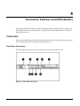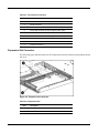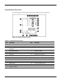
1
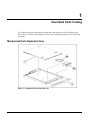
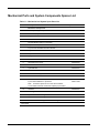
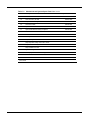
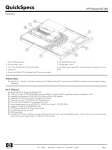
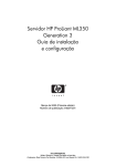
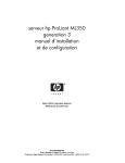
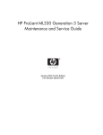
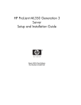
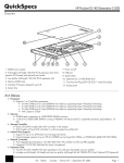
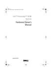
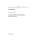
HP ProLiant DL140 Server Maintenance and Service Guide November 2003 (First Edition) Part Number 349117-001 2003 Hewlett-Packard Development Company, L.P. Microsoft® and Windows NT® are U.S. registered trademarks of Microsoft Corporation. Intel® and Pentium® are U.S. registered trademarks of Intel Corporation. Hewlett-Packard Company shall not be liable for technical or editorial errors or omissions contained herein. The information in this document is provided “as is” without warranty of any kind and is subject to change without notice. The warranties for HP products are set forth in the express limited warranty statements accompanying such products. Nothing herein should be construed as constituting an additional warranty. HP ProLiant DL140 Server Maintenance and Service Guide November 2003 (First Edition) Part Number 349117-001 Contents About This Guide ..................................................................................................................iv Audience Assumptions....................................................................................................iv Technician Notes.............................................................................................................iv Where to Go for Additional Help...................................................................................... v IPMI Event Log................................................................................................................ v Telephone Numbers........................................................................................................ v Illustrated Parts Catalog ....................................................................................................... 1 Mechanical Parts Exploded View .................................................................................... 1 System Components Exploded View .............................................................................. 2 Mechanical Parts and System Components Spares List................................................. 3 Removal and Replacement Procedures ............................................................................... 5 Electrostatic Discharge Information................................................................................. 5 Symbols on Equipment ................................................................................................... 6 Rack Warnings ................................................................................................................ 6 Server Warnings and Precautions................................................................................... 7 Removal and Replacement Procedures.......................................................................... 7 Powering Down the Server.............................................................................................. 8 Top Cover ....................................................................................................................... 9 Optical CD-ROM Drive Assembly.................................................................................. 11 Hard Drive Overview ..................................................................................................... 12 Guidelines for Installing ATA Hard Drives ..................................................................... 12 Hard Drive Identification Numbers................................................................................. 13 Hard Drives ................................................................................................................... 14 Power Switch Board ...................................................................................................... 16 PCI Riser Board Assembly............................................................................................ 17 Expansion Board ........................................................................................................... 18 Fan Bracket ................................................................................................................... 19 Fans .............................................................................................................................. 21 Cables ........................................................................................................................... 22 ATA Hard Drive Cables ................................................................................................. 22 Optical CD-ROM Drive Assembly Cable ....................................................................... 23 Front USB Cable ........................................................................................................... 24 HP ProLiant DL140 Server Maintenance and Service Guide ii Power Supply ................................................................................................................ 25 Battery........................................................................................................................... 27 Memory Modules........................................................................................................... 29 Processor ...................................................................................................................... 32 System Board................................................................................................................ 34 Diagnostic Tools ................................................................................................................. 35 Diagnostic Tools Utility Overview .................................................................................. 35 Connectors, Switches, and LED Indicators......................................................................... 36 Connectors .................................................................................................................... 36 Rear Panel Connectors ................................................................................................. 36 Expansion Slot Connector............................................................................................. 37 System Board Connectors ............................................................................................ 38 System Switches ........................................................................................................... 39 System Configuration Switch (SW1) ............................................................................. 40 LED Indicators............................................................................................................... 40 Front Panel LED Indicators ........................................................................................... 40 Rear Panel LED Indicators ............................................................................................ 42 Internal LED Indicator.................................................................................................... 43 IPMI Event Log Code List.............................................................................................. 44 Specifications ..................................................................................................................... 47 System Unit ................................................................................................................... 48 Power Supply ................................................................................................................ 49 Memory ......................................................................................................................... 49 Optical CD-ROM Drive .................................................................................................. 50 Integrated Ultra ATA/100 Controller .............................................................................. 51 Optional Hard Drives ..................................................................................................... 51 ATA Hard Drives ........................................................................................................... 51 Integrated NC7760 Gigabit Server Auto-Switching Network Interface Controller (NIC) 52 HP ProLiant DL140 Server Maintenance and Service Guide iii About This Guide This maintenance and service guide can be used for reference when servicing an HP ProLiant DL140 server. WARNING: To reduce the risk of personal injury from electric shock and hazardous energy levels, only authorized service technicians should attempt to repair this equipment. Improper repairs can create conditions that are hazardous. Audience Assumptions This guide is for service technicians. HP assumes you are qualified in the servicing of computer equipment, trained in recognizing hazards in products with hazardous energy levels, and familiar with weight and stability precautions for rack installations. Technician Notes WARNING: Only authorized technicians trained by HP should attempt to repair this equipment. All troubleshooting and repair procedures are detailed to allow only subassembly/module-level repair. Because of the complexity of the individual boards and subassemblies, no one should attempt to make repairs at the component level or to make modifications to any printed wiring board. Improper repairs can create a safety hazard. WARNING: To reduce the risk of personal injury from electric shock and hazardous energy levels, do not exceed the level of repairs specified in these procedures. Because of the complexity of the individual boards and subassemblies, do not attempt to make repairs at the component level or to make modifications to any printed wiring board. Improper repairs can create conditions that are hazardous. WARNING: To reduce the risk of electric shock or damage to the equipment: • Disconnect power from the system by unplugging all power cords from the power supplies. • Do not disable the power cord grounding plug. The grounding plug is an important safety feature. • Plug the power cord into a grounded (earthed) electrical outlet that is easily accessible at all times. HP ProLiant DL140 Server Maintenance and Service Guide iv CAUTION: To properly ventilate the system, you must provide at least 7.6 cm (3.0 in) of clearance at the front and back of the server. CAUTION: The computer is designed to be electrically grounded (earthed). To ensure proper operation, plug the AC power cord into a properly grounded AC outlet only. NOTE: Any indications of component replacement or printed wiring board modifications may void any warranty. Where to Go for Additional Help In addition to this guide, the following information sources are available • Service Parts Information (SPI) • Service training guides • Service advisories and bulletins • OARS (Onsite Agents Reference Set) IPMI Event Log The server includes an integrated, nonvolatile management log that contains fault and management information. The contents of the IPMI Event Log can be viewed through BIOS Setup. Telephone Numbers For the name of the nearest HP authorized reseller: • In the United States, call 1-800-345-1518. • In Canada, call 1-800-263-5868. For HP technical support: • In the United States and Canada, call 1-800-652-6672. • Outside the United States and Canada, refer to www.hp.com HP ProLiant DL140 Server Maintenance and Service Guide v 1 Illustrated Parts Catalog This chapter provides the illustrated parts breakdown and spare parts list for the HP ProLiant DL140 server. The table in this chapter provides names and ordering numbers for all referenced spare parts. Mechanical Parts Exploded View Figure 1-1: Mechanical parts exploded view HP ProLiant DL140 Server Maintenance and Service Guide 1 System Components Exploded View Figure 1-2: System components exploded view HP ProLiant DL140 Server Maintenance and Service Guide 2 Mechanical Parts and System Components Spares List Table 1-1: Mechanical and System Spare Parts List Item Description Spare Part Number Mechanical Components 1 Access panel (top cover) 348801-001 2 Front Bezel, Mylar and screws 348797-001 3 Single Fan 348795-001 4 Hardware and Plastics Kits 348798-001 4a) HDD Bracket (Drive not included) 4b) CD Bracket (CD-ROM Drive not included) 4c) Processor Heatsink Retention Module* 4d) Cable Tie Downs* 4e) Fan Bracket 4f) System Board Screws* Power 5 325-Watt power supply 348796-001 Boards 6 System Board 348790-001 7 Power Switch Board with cable 348791-001 8 PCI Riser Assembly with bracket 348792-001 Processor 9 a) 2.4-GHz Intel® Xeon™ processor b) 3.2-GHz Intel® Xeon™ processor Note: Processor spares do not come with a heatsink. A new heatsink must be used when replacing a processor. 288599-204 336417-002 10 Heatsink 348789-001 Memory 11 12 a) PC2100 DDR ECC Registered DIMM 512-MB* 261584-041 b) PC2100 DDR ECC Registered DIMM 1-GB* 261585-041 CD-ROM drive assembly (CD-ROM Drive only) 228508-001 * Not shown continued HP ProLiant DL140 Server Maintenance and Service Guide 3 Table 1-1: Item Mechanical and System Spare Parts List continued Description Spare Part Number Hardware 13 ATA hard drive, 80 GB 294934-004 14 Replacement battery, 3-V lithium 166899-001 15 Hard drive cable 348799-001 16 Optical CD-ROM cable 348799-001 17 Optical CD-ROM assembly backplane 348799-001 18 Front USB cable 348800-001 19 Return kit* 349586-001 20 Country kit* 349411-001 20a) Startup, Documentation and Utilities CD 20b) Important Safety Information Guide 20c) Limited Warranty and Material Limitations 20d) Installation Poster Option Kit Spares 21 Third-party cabinet rack-mounting kit* 177854-001 22 Fixed Rails* 353314-001 23 Telco Rails* 353359-001 * Not shown HP ProLiant DL140 Server Maintenance and Service Guide 4 2 Removal and Replacement Procedures This chapter provides subassembly and module-level removal and replacement procedures for HP ProLiant DL140 servers. After completing all necessary removal and replacement procedures, run the diagnostics program to verify that all components operate properly. The following references, diagnostic programs and tools may be used: • Startup, Documentation and Utilities CD • BIOS Setup Utility and IPMI Event Log • Diagnostics software Electrostatic Discharge Information An electrostatic discharge (ESD) can damage static-sensitive devices or microcircuitry. Proper packaging and grounding techniques are required to prevent damage. To prevent damage due to ESD, observe the following precautions: • Transport products in static-safe containers such as conductive tubes, bags, or boxes. • Keep electrostatic-sensitive parts in their containers until they arrive at static-free stations. • Cover workstations with approved static-dissipating material. Use a wrist strap connected to the work surface as well as properly grounded tools and equipment. • Keep the work area free of nonconductive materials such as ordinary plastic assembly aids and foam packing. • Ensure proper grounding before touching a static-sensitive component or assembly. • Avoid touching pins, leads, or circuitry. • Always place drives with the Printed Circuit Board (PCB) assembly-side down. • Use conductive field service tools. HP ProLiant DL140 Server Maintenance and Service Guide 5 Symbols on Equipment Any surface or area of the equipment marked with these symbols indicates the presence of a hot surface or hot component. WARNING: To reduce the risk of injury from a hot component, allow the surface to cool before touching it. To reduce the risk of injury from electric shock hazards, do not open this enclosure. WARNING: Any surface or area of the equipment marked with these symbols indicates the presence of electric shock hazards. The enclosed area contains no operator-serviceable parts. This symbol indicates the presence of electric shock hazards. The enclosed area contains no user or field-serviceable parts. Do not open for any reason. WARNING: To reduce the risk of injury from electric shock hazards, do not open this enclosure. Any RJ-45 receptacle marked with these symbols indicates a network interface connection. WARNING: To reduce the risk of electric shock, fire, or damage to the equipment, do not plug telephone or telecommunications connectors into this receptacle. This label or equivalent is located on the surface of the CD-ROM or DVD-ROM drive. This label indicates that the product is classified as a Class 1 Laser Product. Rack Warnings WARNING: To reduce the risk of personal injury or damage to equipment, always ensure that the rack is adequately stabilized before extending a component outside the rack. A rack may become unstable if more than one component is extended for any reason. Extend only one component at a time. WARNING: To reduce the risk of personal injury or damage to the equipment, be sure that: • The leveling jacks are extended to the floor. • The full weight of the rack rests on the leveling jacks. • The stabilizers are attached to the rack, if it is a single rack installation. • The racks are coupled together in multiple rack installations. WARNING: When installing the server in a telco rack, make certain that the rack frame is adequately secured to the building structure at the top and bottom. WARNING: To reduce the risk of personal injury or damage to the equipment, at least two people are needed to safely unload the rack from the pallet. An empty 42U rack weighs 115 kg (253 lb), is over 2.1 m (7 ft) tall, and may become unstable when being moved on its casters. Do not stand in front of the rack as it rolls down the ramp from the pallet. Handle the rack from both sides. HP ProLiant DL140 Server Maintenance and Service Guide 6 Server Warnings and Precautions WARNING: To reduce the risk of personal injury from hot surfaces, allow the hot-plug drives and the internal system components to cool before touching them. WARNING: To reduce the risk of electric shock or damage to the equipment: • Do not disable the power cord grounding plug. The grounding plug is an important safety feature. • Plug the power cord into a grounded (earthed) electrical outlet that is easily accessible at all times. • Unplug the power cord from the power supply to disconnect power to the equipment. CAUTION: Protect the server from power fluctuations and temporary interruptions with a regulating uninterruptible power supply (UPS). This device protects the hardware from damage caused by power surges and voltage spikes and keeps the system in operation during a power failure. CAUTION: The server must always be operated with the system top cover closed. Proper cooling is not achieved if the system top cover is removed. Removal and Replacement Procedures This chapter discusses preparing the server for servicing and provides step-by-step instructions for the removal or replacement of the: • Top cover • Optical device assembly • Bezel/Mylar/Bezel screws • ATA Hard drives • Optical device assembly backplane • PCI riser board assembly • Expansion board • PCI card guide • Fan bracket with system fans • Cables — ATA cables — Optical CD-ROM device assembly cable — USB Cables • Power supply • Battery • • • Memory modules Processor System board HP ProLiant DL140 Server Maintenance and Service Guide 7 Powering Down the Server The server does not completely power down when the front panel power button is pressed. The button toggles server power between On and Standby. In Standby, the server removes power from most electronics and drives, portions of the power supply and some internal circuitry remain active. To completely remove all power from the system, disconnect the power cord from the server. WARNING: To reduce the risk of injury from electric shock, remove the power cord to completely disconnect power from the system. WARNING: To reduce the risk of personal injury or damage to the equipment, be sure that only one component is extended at a time. A rack may become unstable if more than one component is extended for any reason. WARNING: Because the rack allows you to stack computer components in a vertical rather than a horizontal plane, you must take precautions to provide for rack stability and safety to protect both personnel and property. Heed all cautions and warnings throughout the installation instructions that come with the server. WARNING: To reduce the risk of personal injury or damage to the equipment, place the server on a sturdy table or workbench whenever it is removed from the rack for device accessibility. Refer to the HP ProLiant DL140 Server Setup and Installation Guide for further information on working with racks. CAUTION: Moving the Power On/Off switch to the Off position does not completely remove system power. Some portions of the power supply and some internal circuitry remain active. Disconnect all power cords from the server to remove all power from the system. CAUTION: Electrostatic discharge (ESD) can damage electronic components. Be sure you are properly grounded before beginning any installation procedure. For more information, see “Electrostatic Discharge Information” in this chapter. To power down the server: 1. Press the power button to toggle the server to standby. The power LED on the power button changes from green to off. 2. Listen for the fan noise to stop to indicate that the server is powered down. 3. Disconnect the power cord first from the AC outlet and then from the server. 4. Disconnect all remaining cables on the server rear panel, including cables extending from external connectors on expansion boards. 5. Remove the server from the rack and position it securely on a workbench or other solid surface for stability and safety. HP ProLiant DL140 Server Maintenance and Service Guide 8 Top Cover To access the system board, processor, memory modules, expansion slot, and other internal components, remove the top cover. Observe the following warnings and cautions. WARNING: The front panel Power On/Off switch does not completely shut off all system power. Portions of the power supply and some internal circuitry remain active until AC power is removed. WARNING: To reduce the risk of personal injury from hot surfaces, allow the internal system components to cool before touching them. CAUTION: Before removing the server top cover, be sure that the server is powered down and that the power cord is disconnected from the server or the electrical outlet. CAUTION: To avoid the risk of damage to the system or expansion boards, remove all power cords before installing or removing expansion boards. When the Power On/Off switch is in the Off position, auxiliary power is still connected to the PCI expansion slot and may damage the card. CAUTION: Electrostatic discharge can damage electronic components. Ensure proper grounding before beginning any installation procedure. HP ProLiant DL140 Server Maintenance and Service Guide 9 To remove the top cover: 1. Power down the server. See “Powering Down the Server” in this chapter. 2. Loosen rear thumbscrew. 3. Slide the top cover approximately 1.25 cm (0.5 in) toward the rear of the unit and lift the panel to remove it (1). Figure 2-1: Removing the top cover To replace the top cover, reverse steps 1 through 3. HP ProLiant DL140 Server Maintenance and Service Guide 10 Optical CD-ROM Drive Assembly To remove the Optical CD-ROM drive assembly: 1. Power down the server. See “Powering Down the Server” in this chapter. 2. Remove the top cover. See “Top Cover” in this chapter. 3. Remove the CD-ROM cable and power cable (1). 4. Press in and hold the CD-ROM latch (2) 5. Slide the tray toward the rear of the server until the USB connectors are visible (3). 6. Lift the CD-ROM tray out of the server (4). Figure 2-2: Remove the option CD-ROM drive assembly To replace the assembly, reverse steps 1 through 6. NOTE: See the HP ProLiant Server Setup and Installation Guide for instructions on installing the optional CD-ROM drive. NOTE: If the CD-ROM drive must be replaced due to failure, the Optical CD-ROM Drive backplane must be removed from the failed drive and installed on the replacement. See Chapter 1 for illustrations. HP ProLiant DL140 Server Maintenance and Service Guide 11 Hard Drive Overview The server contains two drive bays for ATA hard drives. There are two ATA channels. One channel is dedicated to the hard drives and the other to the CDROM. The server ships standard with two 1-inch drive trays for use with two 1-inch ATA hard drives. The following sections provide general guidelines and installation procedures for installing or upgrading hard drives. Guidelines for Installing ATA Hard Drives When installing ATA hard drives in the server, observe the following general guidelines: • Populate hard drive bays starting with the lowest ATA device number. Device 0 serves as the primary boot drive. • Set the jumpers on both ATA drives to Cable-Select mode. • Do not add more than two ATA drives in the HP ProLiant DL140 server. IMPORTANT: ATA hard drives must be configured to the Cable-Select mode. NOTE: ATA drives are set to Cable-Select mode by default. NOTE: Refer to the documentation shipped with the hard drive to determine how to set the jumpers on the ATA hard drives to Cable-Select mode, if they are not already set in Cable-Select mode. HP ProLiant DL140 Server Maintenance and Service Guide 12 Hard Drive Identification Numbers The servers include two 1-inch hard drive trays. Hard drives installed in the server are labeled as Device 0 and Device 1 in the following illustration for clarification. IMPORTANT: Always populate hard drive bays starting with the lowest ATA device number. Figure 2-3: ATA device numbers HP ProLiant DL140 Server Maintenance and Service Guide 13 Hard Drives To remove a hard drive from the hard drive bay: 1. Power down the server. See “Powering Down the Server” in this chapter. 2. Remove the top cover. See “Top Cover” in this chapter. 3. Disconnect the ATA cables from hard drives (1,2). Figure 2-4: Disconnecting the cables from the ATA hard drives 4. Disconnect the power cables from the hard drives. Figure 2-5: Disconnecting the hard drive power cables HP ProLiant DL140 Server Maintenance and Service Guide 14 5. Remove the hard drive and hard drive tray: a. Remove the screw that secures the hard drive tray to the chassis (1). b. Slide the tray toward the rear of the server and lift the tray out of the chassis (2). Figure 2-6: Removing the hard drive tray from the chassis 6. Remove the four screws that secure the hard drive to the hard drive tray (1). 7. Remove the hard drive from the hard drive tray (2). Figure 2-7: Removing the hard drive from a hard drive tray Reverse steps 1 through 7 to replace the hard drive. HP ProLiant DL140 Server Maintenance and Service Guide 15 Power Switch Board To remove the Power Switch Board: 1. Power down the server. See “Powering Down the Server” in this chapter. 2. Remove the top cover. See “Top Cover” in this chapter. 3. Remove the cable attached to the Power Switch Board. 4. Remove the two screws (1) and slide the Power Switch Board toward the rear of the server (2) and lift to remove the board. IMPORTANT: Remove the Power Switch Board carefully to avoid damaging the LEDs. Figure 2-8: Removing the Power Switch Board Reverse steps 1 through 4 to replace the Power Switch Board. HP ProLiant DL140 Server Maintenance and Service Guide 16 PCI Riser Board Assembly To remove the PCI riser board assembly: 1. Power down the server. See “Powering Down the Server” in this chapter. 2. Remove the top cover. See “Top Cover” in this chapter. 3. Disconnect any cables connecting an existing expansion board to the system board. 4. Lift and remove the assembly from the server chassis (1). Figure 2-9: Removing the PCI riser board CAUTION: When removing the PCI riser board assembly, avoid damage to the system cables When replacing an expansion board, refer to “Expansion Board” following this procedure. IMPORTANT: Do not replace the PCI riser board assembly in the chassis unless all installation and cabling procedures are complete. Reverse steps 1 through 5 to replace the PCI riser board assembly, ensuring that the assembly seats properly in the retainers on the rear of the chassis and the guides located on the fan bracket. HP ProLiant DL140 Server Maintenance and Service Guide 17 Expansion Board To remove an expansion board: CAUTION: To avoid the risk of damage to the system or expansion boards, remove all power cords before installing or removing an expansion board. When the front panel power switch is off, auxiliary power is still connected to the PCI expansion slot and may damage the card. 1. Power down the server. See “Powering Down the Server” in this chapter. 2. Remove the top cover. See “Top Cover” in this chapter. 3. Disconnect all cables from the expansion board. 4. Remove the PCI riser board assembly. See “PCI Riser Board Assembly” in this chapter. 5. Remove the PCI riser Board assembly screw(1) 6. Apply even pressure to pull the expansion board out of its socket in the PCI riser board assembly (2). Figure 2-10: Removing an expansion board from the PCI riser board assembly Reverse steps 1 through 6 to replace an expansion board. Use the PCI card guide on the assembly to position the board in the socket. IMPORTANT: Ensure that the expansion board is seated securely in the expansion slot before replacing the PCI riser board assembly and access panel. HP ProLiant DL140 Server Maintenance and Service Guide 18 Fan Bracket To remove the fan bracket: 1. Power down the server. See “Powering Down the Server” in this chapter. 2. Remove the top cover. See “Top Cover” in this chapter. 3. Remove the PCI riser board assembly. See “PCI Riser Board Assembly” in this chapter. WARNING: To reduce the risk of personal injury from hot surfaces, allow the internal system components to cool before touching them. 4. Disconnect the fan bracket fan cables (1~5) from the fan connectors on the system board. Figure 2-11: Disconnecting the fan bracket power cables (processor heatsinks removed for clarity) HP ProLiant DL140 Server Maintenance and Service Guide 19 5. Loosen the fan bracket thumbscrew (1). 6. Push the fan bracket toward the power supply side of the chassis to clear the alignment tab and lift fan bracket out (2). Figure 2-12: Unlocking the fan bracket and clearing the fan bracket alignment tab Reverse steps 1 through 6 to replace the fan bracket. IMPORTANT: See Server Access Panel Label or System Board Connecter section later in this manual for correct fan cable connections. CAUTION: When installing fan bracket assembly, avoid damage to the power supply and fan cables HP ProLiant DL140 Server Maintenance and Service Guide 20 Fans The server contains five system fans. The fans are located on the fan bracket. Use the following figure and table to locate the system fans. Figure 2-13: Locating the system fans NOTE: Fans are spared and replaced individually. spare. Each fan listed in table 2-1 is a separate Table 2-1: System Fans Item Component 1 Fan 1 2 Fan 2 3 Fan 3 4 Fan 4 5 Fan 5 HP ProLiant DL140 Server Maintenance and Service Guide 21 Cables The following sections of this guide contain removal and replacement procedures for the standard cables that ship with the server: • ATA/100 cables • Optical CD-Rom Drive Assembly cable. • Front USB cables. ATA Hard Drive Cables To remove the ATA cables: 1. Power down the server. See “Powering Down the Server” in this chapter. 2. Remove the top cover. See “Top Cover” in this chapter. 3. Remove the PCI riser board assembly. See “PCI Riser Board Assembly” in this chapter. 4. Remove the fan bracket. See “Fan Bracket” in this chapter. 5. Disconnect the ATA hard drive cable from the primary ATA controller (1) and hard drive connector (2, 3). Figure 2-14: Disconnecting the ATA cables Reverse steps 1 through 5 to replace the ATA cables. HP ProLiant DL140 Server Maintenance and Service Guide 22 Optical CD-ROM Drive Assembly Cable To remove the optical CD-ROM drive assembly cable: 1. Power down the server. See “Powering Down the Server” in this chapter. 2. Remove the top cover. See “Top Cover” in this chapter. 3. Remove the PCI riser board assembly. See “PCI Riser Board Assembly” in this chapter. 4. Remove the fan bracket. See “Fan Bracket” in this chapter. 5. Disconnect the optical CD-ROM drive assembly cable from the optical device assembly backplane (1). 6. Disconnect the optical CD-ROM drive assembly cable from the system board (2). Figure 2-15: Disconnecting the optical device assembly cable Reverse steps 1 through 6 to replace the optical device assembly cable. HP ProLiant DL140 Server Maintenance and Service Guide 23 Front USB Cable To remove the Front USB cable: 1. Power down the server. See “Powering Down the Server” in this chapter. 2. Remove the top cover. See “Top Cover” in this chapter. 3. Remove the PCI riser board assembly. See “PCI Riser Board Assembly” in this chapter. 4. Remove the fan bracket. See “Fan Bracket” in this chapter. 5. Remove the optical CD-ROM drive assembly; see “Optical CD-ROM Drive Assembly” in this chapter. 6. Remove the hard drive tray(s), See “Hard Drive” in this chapter. 7. Disconnect the USB cable from the system board (1). Remove the USB Cable from the front of the chassis (2) using a flat blade screwdriver to depress plastic tabs (top and bottom of connecters). NOTE: The top tabs can be accessed once the CD-ROM Drive assembly is removed. The bottom tabs can be accessed from the bottom of the server. Figure 2-16: Remove the front USB cable. Reverse steps 1 through 7 to replace the optical device assembly cable. HP ProLiant DL140 Server Maintenance and Service Guide 24 Power Supply To remove the power supply: 1. Power down the server. See “Powering Down the Server” in this chapter. 2. Remove the top cover. See “Top Cover” in this chapter. 3. Remove the PCI riser board assembly. See “PCI Riser Board Assembly” in this chapter. 4. Remove the fan bracket. See “Fan Bracket” in this chapter. 5. Disconnect the hard drive power cables from the hard drives (1). 6. Disconnect the optical CD-ROM drive assembly power cable from the optical CD-ROM drive assembly (2). 7. Disconnect the AUX power supply cable (3) and System power supply cable (4) from the power supply connector on the system board by pressing the locking tab on the side of the connector and pulling upwards. 8. Remove the four power supply screws that secure the power supply unit to the chassis (5), (6). 9. Slide the power supply away from the back of the chassis and lift it from the server (7). HP ProLiant DL140 Server Maintenance and Service Guide 25 Figure 2-17: Removing the power supply Reverse steps 1 through 9 to replace the power supply. HP ProLiant DL140 Server Maintenance and Service Guide 26 Battery If the server no longer automatically displays the correct date and time, check the battery that provides power to the real-time clock. If necessary, replace a used battery with a CR2032 lithium battery. Under normal use, battery life is at least 5 years. WARNING: This server contains either an internal lithium manganese dioxide, or a vanadium pent oxide battery. There is a risk of fire and burns if the battery pack is not handled properly. To reduce the risk of personal injury: • Do not attempt to recharge. • Do not expose to temperatures higher than 60°C (140°F). • Do not disassemble, crush, puncture, short external contacts, or dispose of in fire or water. • Replace only with the spare designated for this product. CAUTION: Loss of BIOS settings occurs when the battery is removed. BIOS settings must be reconfigured whenever the battery is replaced. CAUTION: Batteries, battery packs, and accumulators should not be disposed of together with general household waste. Use the public collection system or return used batteries to your authorized partners or their agents for proper recycling and disposal. HP ProLiant DL140 Server Maintenance and Service Guide 27 To remove the battery: 1. Power down the server. See “Powering Down the Server” in this chapter. 2. Remove the top cover. See “Top Cover” in this chapter. 3. Locate the battery on the system board (1). Figure 2-18: Locating and removing the system battery 4. If necessary, remove the PCI riser board assembly to access the battery location. See “PCI Riser Board Assembly” in this chapter. 5. Press the battery release lever away from the battery (2). 6. Lift the battery on the lever side and pull it out of the holder (3). IMPORTANT: Do not bend the retaining clip during battery replacement. For proper operation, the clip must maintain a position of contact with the battery. Reverse steps 1 through 6 to replace the battery, ensuring that the new battery is installed with the positive side up. HP ProLiant DL140 Server Maintenance and Service Guide 28 Memory Modules The server supports up to four PC2100 DDR ECC registered SDRAM DIMMs installed in four sockets on the system board. NOTE: Populate the DIMM sockets in descending sequential order, starting with DIMM socket 4. Figure 2-19: Identifying DIMM sockets on the system board Table 2-2: DIMM Socket Identification Item Description 1 DIMM socket 1 2 DIMM socket 2 3 DIMM socket 3 4 DIMM socket 4 HP ProLiant DL140 Server Maintenance and Service Guide 29 Observe the following guidelines when installing additional memory: • DIMMs must be industry-standard, 512-MB, or 1-GB, 3-cm (1.2-in), 184-pin PC2100, 266-MHz DDR ECC memory DIMMs. The DDR memory DIMMs must support CAS Latency 2, where CL=2 or greater. They must also contain the mandatory Joint Electronic Device Engineering Council (JEDEC) Serial Presence Detect (SPD) information. • DIMMs installed in the server must be registered DDR, 2.5 volts and 64-bits wide. • Do not mix ECC and non-ECC DIMMs or DIMMs of different speeds. If different types of DIMMs are mixed, the system will not function properly. IMPORTANT: A DIMM can be installed only one way. Be sure to match the key slots on the module with the tabs on the memory slot. Push the module down into the slot until it is fully inserted and properly seated. The system will not recognize improperly aligned or seated DIMMs. To replace a DIMM from the system board: 1. Power down the server. See “Powering Down the Server” in this chapter. CAUTION: ESD can damage electronic components. Ensure that you are properly grounded before beginning any installation procedure. Refer to “Electrostatic Discharge Information” in this chapter. 2. Remove the top cover. See “Top Cover” in this chapter. 3. Press both memory module socket latches outward (1). This action releases the module and partially lifts it out of the socket. 4. Lift out the memory module (2). Figure 2-20: Removing a DIMM from a DIMM socket 5. Align the key slot in the bottom edge of the DIMM with the tab in the expansion socket. HP ProLiant DL140 Server Maintenance and Service Guide 30 6. To install a DIMM, gently push the DIMM into the socket on the system board (1). As the DIMM enters the socket and is properly seated, the latches close (2). Figure 2-21: Installing a DIMM in a DIMM socket CAUTION: Use only HP supplied DIMMs. DIMMs from other sources can adversely affect data integrity. 7. Press down firmly on the DIMM while pushing the latches inward until the latches snap into place. HP ProLiant DL140 Server Maintenance and Service Guide 31 Processor CAUTION: Always use a new heatsink when replacing processors. Failure to use new components can cause damage to the processor. To remove the processor: 1. Power down the server. See “Powering Down the Server” in this chapter. 2. Remove the top cover. See “Top Cover” in this chapter. 3. Locate the processor on the system board. Figure 2-22: Locating the processor on the system board WARNING: To reduce the risk of personal injury from hot surfaces, allow the internal system components to cool before touching them. CAUTION: Processor socket 1 must be populated at all times. Failure to replace the processor results in the system failing to boot and halting during POST. This error prevents the system from functioning properly. HP ProLiant DL140 Server Maintenance and Service Guide 32 4. Disengage the retaining clips on each side of the heatsink (1). 5. Remove the heatsink from the top of the processor (2). Figure 2-23: Disengaging the heatsink retaining clips (one on each side) and removing the heatsink (both retaining clips disengaged) 6. Lift the processor locking lever (1) and lift the processor from the socket (2). Figure 2-24: Removing the processor from the system board Reverse steps 1 through 6 to reinstall the processor and heatsink. CAUTION: Always use a new heatsink when replacing processors. Failure to use new components may result in damage to the processor. HP ProLiant DL140 Server Maintenance and Service Guide 33 System Board To remove the system board: 1. Power down the server. See “Powering Down the Server” in this chapter. 2. Remove the top cover. See “Top Cover” in this chapter. 3. Remove the PCI riser board assembly. See “PCI Riser Board Assembly” in this chapter. 4. Disconnect the fan cables 1 through 5. See “Fans” in this chapter. 5. Remove any DIMMs. See “Memory Modules” in this chapter. 6. Remove the fan bracket. See “Fan Bracket” in this chapter. 7. Disconnect the power supply from the system board. See “Power Supply” in this chapter. 8. Disconnect the optical CD-ROM drive assembly cable from the system board. See “Optical CD-ROM Drive Assembly Cable” in this chapter. 9. Disconnect the ATA drive cables from the hard drives. See “Hard Drives” in this chapter. 10. Remove the processor(s). See “Processor” in this chapter. CAUTION: Always use a new heatsink when replacing processors on the system. Failure to use new components may result in damage to the processor. See “Processor” in this chapter. 11. Remove 8 heatsink retention module screws and heatsink retention module 4 (1). 12. Remove all screws that secure the system board to the chassis (2). 13. Slide the system board toward the front of the chassis, ensuring that the board unseats from all the alignment keys, and lift the board up and away from the keys (3). Figure 2-25: Removing the system board Reverse steps 1 through 13 to replace the system board. HP ProLiant DL140 Server Maintenance and Service Guide 34 3 Diagnostic Tools This chapter provides an overview of the software and firmware diagnostic tools available for HP ProLiant DL140 servers. Diagnostic Tools Utility Overview The following utilities assist in diagnosing problems, testing hardware, and monitoring and managing server operations. Table 3-1: Diagnostic Tools Tool What it is How to run it User Diagnostics A tool to assist testing and/or verifying operation of hardware. If problems are found, the diagnostics package isolates failures down to the replaceable part, whenever possible. Diagnostics and utilities must be accessed when a system configuration error is detected during Power-On Self-Test (POST). Check the www.hp.com website for the most recent version of the HP ProLiant DL140 User Diagnostics. IPMI Event Log A log of system events such as system failures or nonfatal error conditions. View events in the IPMI event log from the BIOS setup. BIOS Setup A utility used to report memory, processor, and system settings. Stores settings information in nonvolatile memory. Run BIOS Setup directly by pressing the DEL key during POST. ROM Upgrade Utility A utility that upgrades the current system ROM. Run this utility from the ROM Upgrade Utility after powering up the system unit. Check the www.hp.com website for the most recent version of the HP ProLiant DL140 ROM. BMC Management Upgrade Utility A utility that upgrades the current system management firmware. Run this utility from the BMC Upgrade Utility after powering up the system unit. Check the www.hp.com website for the most recent version of the HP ProLiant DL140 management firmware. HP ProLiant DL140 Server Maintenance and Service Guide 35 4 Connectors, Switches, and LED Indicators This chapter contains illustrations and tables identifying and describing connectors, switches, and LED indicator locations on the front panel, rear panel, system board, and hard drives for the HP ProLiant DL140 server. Connectors This section contains figures and tables showing connector locations on the front panel, rear panel, PCI riser board assembly, and the system board of the server. Rear Panel Connectors The following figure and table show the connectors on the rear panel of the server. Figure 4-1: Rear panel connectors HP ProLiant DL140 Server Maintenance and Service Guide 36 Table 4-1: Rear Panel Connectors Item Description 1 Power connector 2 Mouse connector 3 Dual USB connector 4 RJ-45 GbE connector for NIC 2 (supports WOL, PXE) 5 Expansion slot 6 RJ-45 GbE connector for NIC 1 (supports WOL, PXE) 7 Video connector 8 Serial connector 9 Keyboard connector Expansion Slot Connector The following figure and table shows the PCI expansion board slot connector and expansion board slot cover. Figure 4-2: Expansion slot connector Table 4-2: Expansion Slot Item Description 1 Expansion board slot cover 2 64-bit 133-MHz PCI-X slot HP ProLiant DL140 Server Maintenance and Service Guide 37 System Board Connectors The following figure and table show system board connectors on the system board. Figure 4-3: System board connectors Table 4-3: System Board Connectors Item Description Item Description 1 PCI Riser Card Connector 14 AUX Power Connector 2 System Configuration Switch (SW1) 15 System Fan 1 Connecter 3 RJ-45 GbE connectors for NIC 1 (bottom) and NIC 2 (top) 16 System Fan 2 Connecter 4 Rear USB Connectors 17 Processor 2 socket 5 VGA Connector 18 System Fan 3 Connecter 6 Serial Port 19 System Fan 4 Connecter 7 Keyboard (Bottom) and Mouse (Top) connectors 20 CD-ROM IDE Connector 8 DIMM socket 1 21 System Fan 5 Connecter 9 DIMM socket 2 22 ATA Hard Drive Connector 10 DIMM socket 3 23 Power Switch Board connecter 11 DIMM socket 4 24 Front Panel USB Connector 12 Power Connector 25 System Battery 13 Processor 1 socket HP ProLiant DL140 Server Maintenance and Service Guide 38 System Switches The server has a switch bank (SW1) for system configuration Refer to the labels on the inside of the server top cover or to the following sections for the proper switch settings. The following figure and table show the location of the system switch. Figure 4-4 : System switches Table 4-4: System Switches Item 1 Description System configuration switch (SW1) HP ProLiant DL140 Server Maintenance and Service Guide 39 System Configuration Switch (SW1) The system configuration switch (SW1) is a four-position switch used for system configuration. Refer to the labels attached to the inside of the server top cover for proper system configuration settings. The following table shows the shipping system configuration switch settings of SW1. Table 4-5: System Configuration Switch (SW1) Settings Position S1 Function Default Description PASSWORD CLEAR OFF ON = PASSWORD CLEAR OFF = NORMAL S2 CMOS CLEAR OFF ON = CMOS CLEAR OFF = NORMAL S3 RECOVERY MODE OFF ON = RECOVERY MODE OFF = NORMAL S4 CONFIGURATION LOCK OFF ON = CONFIGURATION LOCK OFF = NORMAL NOTE: “On” activates the function. LED Indicators This section contains illustrations and descriptions for the following internal and external server LEDs: • Front panel • Rear panel • System board Front Panel LED Indicators Front panel status LEDs allow constant monitoring of basic system functions while the server is operating. HP ProLiant DL140 Server Maintenance and Service Guide 40 Figure 4-5: Front panel LEDs Table 4-6: Front Panel LEDs Item LED Description Status 1 Optical CD-ROM drive activity 2 Power On/Off Button 3 NIC 2 link/activity 4 NIC 1 link/activity 5 Server Status 6 Hard drive activity On = Activity Off = No activity Green = System has AC power and is turned on. Off = Standby mode or System is not powered on. Blinking Green = Hibernate. On (Green) = Link Off = No Link Blinking Green = Activity On (Green) = Link Off = No Link Blinking Green = Activity Off = Good Red = Critical Error as following: • At least one fan failure • At least one processor failure • At least one of the temperature sensors reached critical temperature • At least one processor VRM failure • At least one memory module exceeds the max single bit error rate Blinking Green = Activity Off = No Activity HP ProLiant DL140 Server Maintenance and Service Guide 41 Rear Panel LED Indicators The server rear panel contains two LEDs that allow monitoring of network activity and server identification. Figure 4-6: Rear panel LEDs Table 4-7: Rear Panel LEDs Item Description Status 1 NIC 1 link/activity On (Green) = Link Off = No link Blinking Amber = Activity 2 NIC 2 link/activity On (Green) = Link Off = No link Blinking Amber = Activity HP ProLiant DL140 Server Maintenance and Service Guide 42 Internal LED Indicator The system board contains an internal power status LED for use during troubleshooting operations. When the LED is illuminated, adequate power is available to the system from the power supply. If the LED is not illuminated, either the power cord is not connected or the power supply has failed. Figure 4-7: Power status LEDs Table 4-8: Power status LED Item Description Location 1 AC Power CR10 On = Activity Off = No activity 2 Multi bit error CR15 On = Activity Off = No activity 3 Single bit error CR17 On = Activity Off = No activity HP ProLiant DL140 Server Maintenance and Service Guide 43 IPMI Event Log Code List The IPMI Event Log Code List can be used in conjunction with the IPMI Event log found in the BIOS setup to assist in troubleshooting of the unit. Fan Discrete Event/Reading class. Sensor numbers are from 01h to 05h. Error Type* * See IPMI event log description details. Memory Discrete Event /Reading class. Sensor number is 06h. Error Type Data1 Data2 Data3 Correctable ECC 00h FFh FFh Uncorrectable ECC 01h FFh FFh Processor Discrete Event /Reading class. Sensor numbers are from 07h to 08h. Error Type Data1 Data2 Data3 IERR 00h FFh FFh Presence detected 07h FFh FFh Data1 Data2 Data3 01h FFh FFh Voltage Discrete Event /Reading class. Sensor number is 09h. Error Type VRM Failure asserted Threshold Event /Reading class. Sensor numbers are from 0Eh to 12h. Error Type Data1 Data2 Data3 Voltage Over Err 59h (Read Value) (Threshold Value) Voltage Over Warn 57h (Read Value) (Threshold Value) Voltage Low Err 52h (Read Value) (Threshold Value) Voltage Low Warn 50h (Read Value) (Threshold Value) HP ProLiant DL140 Server Maintenance and Service Guide 44 Temperature Discrete Event /Reading class. Sensor number is 0Ch. Error Type Thermal Trip State asserted Data1 Data2 Data3 01h FFh FFh Threshold Event /Reading class. Sensor numbers are 0Ah, 0Bh and 0Dh. Error Type Data1 Data2 Data3 Thermal Trip State asserted 01h FFh FFh Upper Critical 59h (Read Value) (Threshold Value) Upper Non-critical 57h (Read Value) (Threshold Value) System Firmware Error Type Data1 Data2 Data3 CMOS_MEMORY_SIZE_ERR E0h 00h 01h PASSWORD_CHECK_ERR PASSWORD_CHECK_ERR _NON_CRITICAL CMOS_BATTERY_ERR E0h 00h 02h E0h 00h 03h E0h 00h 04h System Firmware Error Unspecified CMOS_DIAG_STS_ERR E0h 00h 05h CMOS_CHECKSUM_ERR E0h 00h 06h CMOS_DATE_TIME_ERR E0h 00h 07h PMM_MEM_ALLOC_ERR E0h 00h 08h SEGMENT_REG_ERR E0h 00h 09h ADM_MODULE_ERR E0h 00h 0Ah LANGUAGE_MODULE_ERR E0h 00h 0Bh E0h 02h 01h HDD_0_ERR E0h 03h 01h HDD_1_ERR E0h 03h 02h HDD_2_ERR E0h 03h 03h HDD_3_ERR E0h 03h 04h ATAPI_0_ERR E0h 03h 05h ATAPI_1_ERR E0h 03h 06h ATAPI_2_ERR E0h 03h 07h ATAPI_3_ERR E0h 03h 08h ATA_SMART_FEATURE_ERR E0h 03h 09h E0h 04h 01h No usable system memory Unrecoverable hard-disk/ATAPI/IDE device failure Unrecoverable system-board failure REFRESH_TIMER_ERR. HP ProLiant DL140 Server Maintenance and Service Guide 45 Error Type Data1 Data2 Data3 DMAC_PAGE_REG_ERR E0h 04h 02h DMAC1_CH_REG_ERR E0h 04h 03h DMAC2_CH_REG_ERR E0h 04h 04h TIMER_COUNT_RW_ERR E0h 04h 05h KBC_BAT_TEST_ERR E0h 07h 01h INSERT_FUNC_KEY_ERR E0h 07h 02h KBD_LOCK_ERR E0h 07h 03h KBC_INTERFACE_ERR E0h 07h 04h NO_KBD_ERR E0h 07h 05h DISPLAY_MEMORY_ERR E0h 0Ah 01h CMOS_DISPLAY_ERR E0h 0Ah 02h Option ROM initialization C0h 08h FFh Video initialization C0h 09h FFh Keyboard controller initialization C0h 0Ch FFh Keyboard test C0h 17h FFh Data1 Data2 Unrecoverable PS/2 or USB keyboard failure No video device detected System Firmware Progress Watchdog Timer Error Type Hard Reset C1h Data3 xxh 2 FFh FFh FFh Power Down C2h xxh 2 Power Cycle C3h xxh 2 Note 1: FFh indicates an unspecified value. Note 2: 7:4 interrupt type 0h = none 1h = SMI 2h = NMI 3h = Messaging Interrupt Fh = unspecified all other = reserved 3:0 timer use at expiration: 0h = reserved 1h = BIOS FRB2 2h = BIOS/POST 3h = OS Load 4h = SMS/OS 5h = OEM Fh = unspecified all other = reserved HP ProLiant DL140 Server Maintenance and Service Guide 46 5 Specifications This chapter provides operating and performance specifications for HP ProLiant DL140 server components and optional hardware, including: • System unit • Power supply • Memory • Optical CD-ROM drive Assembly • Integrated Ultra ATA/100 controller • Optional ATA hard drives • Integrated Dual Broadcom 10/100/1000 NICs (Wake on LAN and PXE capable) HP ProLiant DL140 Server Maintenance and Service Guide 47 System Unit Table 5-1: System Unit Specifications Item Description Height 4.37 cm (1.72 in) Depth 60.22 cm (23.7 in) Width 43.0 cm (16.9 in) Weight (maximum) 11.00 kg (24.2 lb) U.S. and international input voltage requirements Rated input voltage 100 VAC to 240 VAC Rated input frequency 50 Hz to 60 Hz Rated input current 4.5A (100-120 V) / 2.5A (200-240 V) Rated input power 440 W BTUs per hour Temperature range 1509 1 Operating 10°C to 35°C (50°F to 93°F) Shipping -40°C to 60°C (-40°F to 140°F) 2 Relative humidity (non-condensing) Operating 10% to 90% Non-operating 10% to 95% Maximum wet-bulb temperature 28°C (82.4°F) 1 Operating temperature has an altitude derating of 1°C per 308.4 M (1.8°F per 1000 ft). No direct sunlight. 2 Storage maximum humidity of 95 percent based on maximum temperature of 45°C (113°F). Altitude minimum for storage is 70 KPa. HP ProLiant DL140 Server Maintenance and Service Guide 48 Power Supply Table 5-2: Power Supply Specifications Item Description Input characteristics Rated input voltage 100 VAC to 240 VAC Rated input line 110VAC / 220 VAC Frequency range 50 to 60 Hz Rated input power 440 W Rated input current 4.5 A (100 V) to 2.1 A (240 V) Output characteristics Steady state power 325 W Maximum peak power 422 W for 15 seconds. Ambient temperature range Operating 10°C to 48°C (50°F to 118°F) Non-operating -40°C to 70°C (-40°F to 158°F) Relative humidity (non-condensing) Operating 5% to 85% Non-operating 5% to 95% Dielectric voltage withstand Input to output 1800 VAC/second Input to ground 1800 VAC/second Maximum wet-bulb temperature 28°C (82.4°F) Memory Table 5-3: SDRAM DIMM Specifications Item Description Size 512 MB and 1GB Speed 266 MHz Width 64 bits Type PC2100 ECC registered DDR SDRAM DIMMs Note: DIMMs must be industry-standard 184-pin PC2100 DDR DIMMs. The DDR DIMMs must support CAS Latency 2, or greater. They must also contain the mandatory Joint Electronic Device Engineering Council (JEDEC) Serial Presence Detect (SPD). Use HP supplied DIMMs only. HP ProLiant DL140 Server Maintenance and Service Guide 49 Optical CD-ROM Drive Table 5-4: Optical CD-ROM Drive Specifications Item Description Applicable disk formats CD-DA, CD-ROM (mode 1 and 2); CD-XA (mode 2, Form 1 and 2), CD-1 Ready; CD-Extra; Video CD, Photo CD (single and multiple session) Capacity 550 MB (mode 1, 12 cm) 640 MB (mode 2, 12 cm) Block size 2638, 2352 bytes (mode 0); 2352, 2340, 2336, 2048 bytes (mode 1); 2352, 2340, 2336, 2048, bytes (mode 2) Dimensions (Bezel Included) Height 1.27 cm (0.5 in) Depth 13.17 cm (5.39 in) Width 13.26 cm (5.22 in) Weight <340 g (<11.98 oz) Data transfer rate Sustained 150 KBps (sustained 1X) 3.6 Mbytes/s (sustained, 24X Outer Diameter) Burst 16.6 Mbytes/s (burst) Access times (typical) Full stroke 300 ms (average) Random 140 ms (average) Disc diameter 12 cm, 8 cm (4.7 in, 3.15 in) Disc thickness 0.12 cm Track pitch 1.6 µm Cache/buffer 128 KB Startup time <10s Stop time <4s (single); <30s (multi-session) Laser parameters Type Semiconductor Laser Wave length 795nm Output power <0.25 mW Operating conditions Temperature 5° to 55°C (41° to 131°F) Humidity 10% to 80% HP ProLiant DL140 Server Maintenance and Service Guide 50 Integrated Ultra ATA/100 Controller Table 5-5: Ultra ATA/100 Controller Specifications Item Description Simultaneous drive transfer channels 2 channels Transfer rate synchronous (Max) 100 MBps Data transfer method 32-bit PCI bus master Drive support Ultra ATA, EIDE & Fast ATA-2 PCI bus transfer rate (maximum) 266 MBps Data transfer modes UDMA Modes 5/4/3/2/1/0, DMA Modes 2/1/0, PIO Modes 4/3/2/1/0 Protocol ATA/100 compatible Feature CRC (Cyclical Redundancy Check) Buffer size 128 byte Optional Hard Drives ATA Hard Drives Table 5-6: ATA Hard Drive Specifications 80 GB Formatted capacity 80,026 MB Height Third, 2.54 cm (1.0 in) Size 8.89 cm (3.5 in) Interface ATA/100 Transfer rate synchronous (max) Single track 100 MBps 0.8 ms Average 9.0 ms Full stroke 17.0 ms Rotational speed 7,200 rpm Bytes/sector 512 Logical blocks 160,086,528 Operating temperature Celsius 5° to 55° Fahrenheit 41° to 131° HP ProLiant DL140 Server Maintenance and Service Guide 51 Integrated Broadcom 10/100/1000 Gigabit Server Auto-Switching Network Interface Controller (NIC) Table 5-7: Integrated Broadcom 10/100/1000 Gigabit Server Auto-Switching Network Interface Controller (NIC) Specifications (WOL and PXE capable) Item Description Network interface 10Base-T/100Base-TX/1000Base-T Ethernet Compatibility IEEE 802.3 Data transfer method 64-bit, 133MHz PCI(X)1.0 Network transfer rate 10/100/1000 Mbps Connector RJ-45 I/O address and interrupt Plug and Play PCI Emissions standards FCC class B HP ProLiant DL140 Server Maintenance and Service Guide 52