1
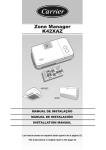
Zone Manager
40KMC------301
40KMQ------301
40QNC------3
40QNQ------3
INSTALLATION MANUAL
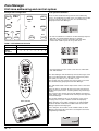
Zone Manager
This control system only operates with indoor units of the following models:
40KMC------301 and 40KMQ------301 Cassette, 40QNC------3 and 40QNQ------3 Hiwall
For installation instructions of this unit, refer to the relevant manuals.
Contents
Page
General information ....................................................................................
2
Characteristics ............................................................................................
2
Choosing the installation site ......................................................................
3
Installation ..................................................................................................
4
Electrical connections .................................................................................
5/6
Configuration ..............................................................................................
7/12
Unit zone addressing .................................................................................. 13/14
Test System ................................................................................................
14
Smart Start function ....................................................................................
15
Trouble Shooting ........................................................................................
16
ENGLISH
Installation manual
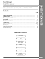
Installation Flow Chart
Read manual
Install
Zone Manager
Wire Zone Manager
and unit network
Configure
Zone Manager
Address unit by zone
Test System
Operate
Zone Manager
GB - 1
Zone Manager
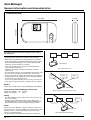
General information and characteristics
Dimensions (mm)
7-1/2" (190,5)
4-1/2" (107,9)
1-1/2"(39)
IMPORTANT:
Read this instruction manual thoroughly before starting
the installation.
• For trouble-free installation, which should be carried out by a
qualified installer, follow the installation chart sequence.
• Follow all current national safety code requirements. In particular
ensure that a properly sized and connected ground wire is in place.
• After installation thoroughly test the system operation and
explain all system functions to the owner.
• Leave this manual with the owner for consultation during
future periodic maintenance.
• Dispose of packaging material in accordance with local
requirements.
• The manufacturer denies any responsibility and warranty shall
be void if these installation instructions are not observed.
• Inspect equipment for damage due to improper transportation
or handling: file an immediate claim with the shipping company.
Do not install or use damaged units.
• In case of any malfunctioning turn the unit off, disconnect the
mains power supply and contact a qualified service engineer.
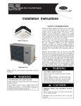
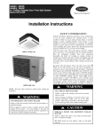
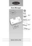
Unit 1
Unit 2
Unit 3
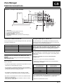
Zone Manager
Correct layout Daisy chain
Unit 2
Unit 1
Unit 3
Models
There is only 1 model, which is easily configurable for all installations.
Zone Manager
Products that the Zone Manager can Interface
Incorrect layout must not be used Start Layout
40KMC and 40KMQ------301 Cassette,
40QNC and 40QNQ------3
Hiwall.
Wiring
• The Zone Manager can be connected to one unit (that is the
first in the network).
• Each unit must be connected one after the other (daisy chain).
• If the Zone Manager is to use its room sensor the controller has to
be located in the same area as the addressed unit(s) number 1.
Unit 1
Unit 2
Unit 3
Power
Note that the Zone Manager requires no batteries and is not
"power stealing". It requires 12 VDC to be connected for proper
operation, which is easily obtained from any of the unit by
means of an auxiliary board.
The Zone Manager will not operate without this connection.
GB - 2
Zone Manager
Not recommended TEE connection
Unit 4
Zone Manager
Choosing the installation site
ENGLISH
5' (1,5 m)
Minimum clearances
The Zone Manager Location
The Zone Manager can be located anywhere.
However, if the installation requires the systems in the location
in zone 1 to use the Air Sensor on the Zone Manager; then, the
controller should be mounted:
• Approximately 5 feet (1.5 m) from floor.
• In the same area where the units from group are located,
preferably on an inside partitioning wall.
• On a section of wall without pipes or duct work.
If the air sensor on the Zone Manager has been selected, it
should NOT be mounted:
• Close to a window, on an outside wall, or next to a door
leading to the outside.
• Exposed to direct light or heat from a lamp, sun, fireplace, or
other temperature-radiating object which may cause a false
reading.
• Close to or in direct airflow of a heating or cooling supply.
• In areas with poor air circulation, such as behind a door or in
an alcove.
GB - 3
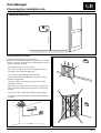
Zone Manager
Installation
Zone Manager
Zone Manager
ZONE 1
ZONE 1
ZONE ..
ZONE ..
ZONE 8
ZONE 8
Considerations
•
•
•
•
Maximum of 150 feet (500 m) of total network wiring.
Maximum of 32 units allowed on a system.
Maximum number of zones 8.
Only zone 1 can use the room sensor located on the Zone Manager.
Network wiring must be daisy chained.
CAUTION:
Star configuration can cause improper operation of the
Zone Manager.
1/4" (6 mm) of extra wire [strip no more than 1/4" (6 mm) of
insulation from each wire to prevent adjacent wires from
shorting together when connected].
• Match and connect equipment wires to proper terminals in the
connector block (See section "Electrical connections").
Both power and communication wires must be connected
correctly for proper Zone Manager operation.
• Push any excess wire into the wall and against mounting base.
If the air sensor is being used on the Zone Manager, seal
hole in wall to prevent air leaks.
Leaks can affect sensor operation.
• Close the Zone Manager assembly making sure pins on back
of circuit board align with sockets in connector.
Mounting
WARNING:
Before installing the Zone Manager, turn off all power to
the unit that will supply power to the Zone Manager.
Electrical shock can cause personal injury or death.
• Turn off all power to the unit.
Mounting
Mounting screws
Connection cables
Holes
• Open the Zone Manager rear door (mounting base) to expose
mounting holes.
The base can be removed to simplify mounting (snap apart
carefully at hinge to separate mounting base from remainder
of the Zone Manager).
• Route the Zone Manager wires through the large hole in the
mounting base.
Level mounting base against wall (for aesthetic value only the
Zone Manager need not be level for proper operation) and
mark the wall through the 2 mounting holes.
• Drill two 3/16" (5 mm) mounting holes in wall where marked.
• Secure mounting base to wall with 2 screws and anchors
provided (additional anchoring holes available for more
secure mounting if needed), making sure all wires extend
through hole in mounting base.
• Adjust length and routing of each wire to reach the proper
terminal in the connector block on the mounting base, with
GB - 4
Zone Manager
Electrical connections
ENGLISH
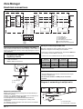
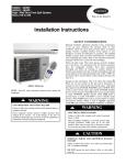
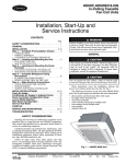
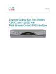
Diagram 1: wiring for Zone manager
WHITE
A
GREY
C
BLUE
B
RED
12 V
BLACK
GND
1
GND
+12V
-RS485B
+RS485A
C
6
Main board
Communication board (supplied with the kit)
5-cable wiring (supplied with the kit)
Auxiliary terminal block (supplied with the kit)
Wiring by the installer
Zone Manager terminal block (mounted on the Zone Manager)
Indoor unit
Installation of the kit into the unit
Wiring Zone Manager to master unit
For the connection of the Zone Manager to the unit, you need
to install the following kit:
The Zone Manager has the ability to control up to 32 units.
To insure the correct operation of this system the wiring must
be installed using the following guidelines.
Unit type
Kit part number
40 KMC------301
33MC9004
40 KMQ------301
33MC9004
40 QNC------3
33MC9004
40 QNC------3
33MC9004
CAUTION:
Improper wiring or installation may damage the Zone
Manager.
Check to make sure wiring is correct before proceeding
with turning on unit.
Please note that:
• A communication board is required for all products that are
networked to a Zone Manager system.
• The kit includes a communication board, a pre-assembled
5-cable wiring connected to a 6-way connector and to a 5-way
terminal block and one installation manual.
• The auxiliary terminal block (5 poles) must be secured
according to the 33MC9004 wiring kit installation manual.
• By means of the J8 connector, connect the communication
board to the main board.
In the case of troubles during installation, remove the main
board from the control box.
WARNING:
Before connecting any wiring to the Zone Manager , turn
off all power to the unit that will supply power to the Zone
Manager. Electrical shock can cause personal injury or
death.
The Zone Manager is connected to the master unit using the
following instructions. Refer to Diagram 1 when making these
connections.
AUXILIARY TERMINAL BLOCK AND ZONE MANAGER
CONNECTION
• Loosen the screws of the auxiliary terminal block.
• Connect the auxiliary terminal block to the Zone Manager
terminal block as follows:
Auxiliary terminal
block terminals
Zone Manager
terminal block
+12V Red
+12V
GND Black
GND
A White
+R5485A
C Grey
C
B Blue
-R5485B
Use a standard 18AWG solid thermostat wire. The communication
cable needs to be 3 wires surrounded with a shielded cable.
• Tighten the terminal block screws.
GB - 5
Zone Manager
Electrical connections
Diagram 2: multiple units in a network configuration
WHITE
A
A
A
GREY
C
C
C
BLUE
B
B
B
RED
12V
12V
12V
BLACK
GND
GND
GND
GND
+12V
C
-RS485B
+RS485A
NOTE: The cable shield of the zone manager communication
cable must be earthed from the air conditioner side (indoor
unit); insulate the latter from the zone manager side in order to
prevent any accidental contact, which might damage the device
(Zone Manager).
Wiring Materials required
(supplied by installer)
• 1 small screwdriver
• 18AWG solid thermostat wire
First indoor unit
Second indoor unit
Third indoor unit
Zone Manager terminal block
Communication board
To the other main terminal boards
Wiring for networking multiple units
Materials required for wiring multiple units into a network.
Reference Diagram 2 when doing this installation.
• Loosen the screws on terminals A, C , B, 12V and GND from
the auxiliary terminal block in all units.
• Connect the first terminal block to the other terminal block:
2nd Auxiliary
3rd Auxiliary
1 st Auxiliary
terminal block terminal block terminal block
A
A
A
_
_
_
C
C
C
_
B
B
B
_
• Tighten all the screws.
CAUTION:
• The Zone Manager must only be connected to one single
auxiliary terminal block.
• Do not tie the shield to a GND post at more than 1
location.
Zone Manager
Unit
Diagram 3: networking of multiple units
UNIT 1
UNIT 2
UNIT 3
UNIT ....
Networking multiple units
Multiple units can be connected together and controlled by a
single Zone Manager.
Diagram 3 is a block diagram of multiple units networked into
a system controlled by 1 Zone Manager.
To accomplish this the communication boards from the
networked units must be wired together in a daisy chain
configuration.
The following section describes how to do the wire installation
for a networked system.
GB - 6
Zone Manager
Power connection
Communication connections
Zone Manager
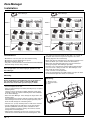
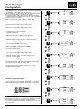
Configuration
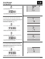
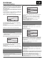
Configuration options are intended to be selected at installation
and normally are not modified by the end user.
These options are not discussed in the end user’s manual and
therefore must be made as part of the installation.
A special procedure allows entry into the configuration mode.
The Zone Manager will automatically exit this mode if no button
is pressed within 20 seconds.
While in configuration mode, 9 choices can be made:
• Fahrenheit (F) or Celsius (C) (Default: Celsius).
ENGLISH
1-
"SET TIME"
F
C
"SET TIME"
On
OF
"SET TIME"
H
C
up
down
up
down
2-
up
down
up
• Room Air Override ON or OFF (Default: OFF).
• Cooling only (C) or Heat Pump (H)
(Default: Heat Pump).
down
3-
• Auto Mode Setback Deadband: Value Adjustment.
up
down
up
down
• Number of Zone Installed (Default 1): Value Adjustment.
• Smart Start ON or OFF (Default: ON).
up
4-
• Military Time (ON) or Standard Time (OFF)
(Default: Standard Time).
"SET TIME"
5....16
"SET TIME"
1....8
down
up
down
• Local unit override ON or OFF (Default: OFF).
• Ability to not allow mode or schedule changes: Lock
(Default : UL, Unlocked)
up
5-
down
up
down
In configuration mode ON is represented by the display "On"
and OFF is represented by the display "OF."
An explanation for each of these and how to enter the
configuration mode follows.
6-
"SET TIME"
On
OF
"SET TIME"
On
OF
"SET TIME"
On
OF
up
down
up
down
To enter configuration mode
7-
Press and hold the " FAN" button for approximately 5 seconds
until the normal display disappears and reads "1-" and either
"C" or "F". You are now in the configuration mode.
up
down
up
down
8-
up
down
up
down
NOTE:
If no button is pressed for 20 seconds, the Zone Manager will
exit configuration mode and resume normal operation.
To re-enter configuration mode, "FAN" button must be pressed
and held again.
9-
"SET TIME"
Lo
UL
up
down
GB - 7
Zone Manager
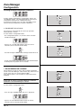
Configuration
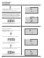
To change multiple configuration parameters:
To make another modification to configuration, depress the
"SET TIME/ TEMP" button. This will toggle between selecting the
Configuration Option and the Configuration Value.
To change the selection, press the "up" and "down" arrows
until the desired configuration selection is displayed.
1- FAHRENHEIT OR CELSIUS
Select between Fahrenheit (F) or Celsius (C) operation.
Factory default is Celsius.
To select while in configuration mode:
• The Configuration Option ("1-") and the current selection
should be displayed.
• Depress the "SET TIME/ TEMP" button to alter the current
selection (current selection will now blink).
up
down
• Use either the "up" or "down" button to change between "F" or "C".
• To end configuration, either depress the "END
or do not press any buttons for 20 seconds.
PROGRAM"
button
2- ROOM THERMISTOR OVERRIDE
Select whether the units in zone 1 will use room temperature
sensor in the Zone Manager " ON"or whether they will use the air
sensor at the units "OF ". Factory default is OFF.
If the chosen option is "ON" the room air temperature will be
displayed.
CAUTION:
If the room air sensor on the Zone Manager is selected,
installation of the Zone Manager is critical.
To select while in configuration mode:
up
down
• Press the "up" or "down" button until "2-" is displayed.
• Depress the "SET TIME/ TEMP" button to alter the current
selection (current selection will now blink).
GB - 8
Zone Manager
Configuration
ENGLISH
up
down
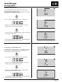
• Use either the "up" or "down" button to change between "OF"
(OFF) and "On" (ON).
• To end configuration, either depress the "END
or do not push any buttons for 20 seconds.
PROGRAM"
button
3- COOLING ONLY OR HEAT PUMP: SELECTION
Select whether the system is a cooling only or Heat Pump system.
If there is a combination of cooling only and heat pump units on
the system, then Heat Pump must be selected.
Factory default is Heat Pump.
To select when in configuration mode:
up
down
• Press the "up" or "down" button until "3-" is displayed.
• Depress the "SET TIME/TEMP" button to change the current
selection (current selection will now blink).
up
down
• Use either the "up" or "down" button to change between "H"
(Heat Pump) and "C" (Cooling only).
• To end configuration, either depress the "END
do not push any buttons for 20 seconds.
PROGRAM"
button
4 - AUTO MODE SETBACK DEADBAND: ADJUSTMENT
Select the number of degrees to setback the heating and cooling
setpoints while a unit is in auto mode during a setback period.
Factory default is 9°C (or 18°F).
To select when in configuration mode:
up
down
• Press the "up" or "down" button until "4-" is displayed.
• Depress the "SET TIME/TEMP" button to change the current
selection (current selection will now blink).
GB - 9
Zone Manager
Configuration
up
down
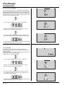
• Use either the "up" or "down" button to change the current
number of degrees to setback.
(Allowable selections are 4 to 18°C or 8 to 36°F).
NOTE:
The scale of the temperature is dependent up on the currently
configured scale. If the configuration item "1-" is set to "F" and
configuration item "4-" has a value of 16, then an Auto Mode
Setback Deadband of 16°F will be used. If the configuration
item "1-" is set to "C" and configuration item "4-" has a value of
16, then an Auto Mode Setback Deadband of 16°C will be
used.
• To end configuration, either depress the "END
or do not push any buttons for 20 seconds.
PROGRAM"
button
5- ZONE CONFIGURATION
This adjustment controls the number of zones on the system.
Factory default is 1 zone.
To adjust when in configuration mode:
up
down
• Press the "up" or "down" button until "5-" is displayed.
• Depress the "SET TIME/ TEMP" button to change the current
selection (current selection will now blink).
up
down
• Use either the "up" or "down" button to change the number of
zones installed, allowable selection are 1- 8 zones.
• To end configuration, either depress the "END
or do not push any buttons for 20 seconds.
GB - 10
PROGRAM"
button
Zone Manager
Configuration
ENGLISH
6- SMART START ACTIVE
This selection allows you to select whether Smart Start is
active or not. Factory default is "On".
See Algorithm Descriptions for an explanation of Smart Start.
To adjust when in configuration mode:
up
down
• Press the "up" or "down" button until "6-" is displayed.
• Depress the "SET TIME/ TEMP" button to change the current
selection (current selection will now blink).
up
down
• Use either the "up" or "down" button to change your selection
to "On" (ON) or "OF" (OFF).
• To end configuration, either depress the "END
or do not push any buttons for 20 seconds.
PROGRAM"
button
7- MILITARY OR STANDARD TIME
This adjustment controls whether time is displayed in military
(24-hour clock) or standard format (12-hour AM/PM clock).
Factory default is "On" for military time.
up
down
• Press the "up" or "down" button until "7-" is displayed.
• Depress the "SET TIME/ TEMP" button to change the current
selection (current selection will now blink).
up
down
• Use either the "up" or "down" button to change to "On"
(military time) or "OF" (standard time).
• To end configuration, either depress the "END
or do not push any buttons for 20 seconds.
PROGRAM"
button
GB - 11
Zone Manager
Configuration
8- LOCAL UNIT OVERRIDE
If Local Unit Override is active, certain information (operating
mode, desired temperature, fanspeed, louver setting) from the
Zone Manager will be ignored by a unit that has recently been
locally controlled.The unit will control to the local settings for at
least one hour using a local user interface. Factory default is "OF".
To adjust when in configuration mode:
up
down
• Press the "up" or "down" button until "8-" is displayed.
• Depress the "SET TIME/TEMP" button to change the current
selection (current selection will now blink).
up
down
• Use either the "up" or "down" button to change to "On" for active
Local Unit Override or "OF" for disabled Local Unit override.
• To end configuration, either depress the " END
or do not push any buttons for 20 seconds.
PROGRAM"
button
9- LOCK MODE
If this option is active (Lo) after 4 minutes the installer exits
installation mode, the operator will not be able to change mode or
program schedule.
If the operator press the "MODE" or " PROGRAM" button "Lo:c" will
be displayed. Default is unlocked (UL ).
To adjust when in configuration mode:
up
down
• Press the "up" or "down" button until "9-" is displayed.
• Depress the "SET TIME/ TEMP" button to change the current
selection (current selection will now blink).
up
down
• Use either the "up" or "down" button to change to "LO" to
Lock mode and program schedule or "U L" to allow the end
user modify these parameters.
• To end configuration, either depress the " END
or do not push any buttons for 20 seconds.
GB - 12
PROGRAM"
button
Zone Manager
Unit zone addressing
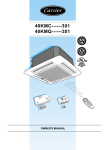
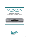
Unit zone addressing
The units must have their communications address changed to the
zone number they will occupy.
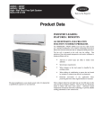
Figure shows an example using 9 units and 4 zones.
For this example, the values shown in Table 1 page 14 should
be used.
For this example, units B, C, E, H, and I will occupy Zone 4.
Therefore their communications addresses should be
configured to address 4.
The numbering of the zones must begin with Zone 1.
Any further zones must be added in a sequential order.
For example, configuring the zones 1, 2, 3, and 5 will result in
improper operation.
(Fault code C4 would be seen).
ENGLISH
Configuring the communication address using the
Room Controller
Configuring the electronic main board
The instructions below refer to the unit configuration shown in the
drawing on the next page.
• Each unit must have its own address (“21” in the room
controller menu) which will be different from the others.
The example shows 9 units, so 9 different addresses will have
to be configured.
• Suppose you want to configure units A and D in room
(zone) 1.
Keeping the Room controller OFF, press the “UP” and “DOWN”
buttons simultaneously for at least 5 seconds
Configuring the communication address using the
IR remote
The instructions below refer to the unit configuration shown in
the drawing on the next page.
• Each unit must have its own address
("UAdr" in the IR remote control menu) which will be different
from the others. The example shows 9 units, so 9 different
addresses will have to be configured.
• Suppose you want to configure units A and D in room (zone)
1. Keeping the IR remote control OFF, press the keys mode
and louver
simultaneously for at least 5 seconds to
access to the configuration menus.
and
Use "MODE" button to select item "UAdr" and then use
buttons to select address "1".
button to send a message to unit "A".
Now press louver
A "beep" confirms the address reception.
Make sure one same address is not sent to the other units.
button to select address "2" and by means of louver
• Press
button send the message to unit "D".
button again to select item " ZONE".
Press mode
and
buttons to select zone "1".
Use
button to send the message to unit
Press louver
"A" and "D".
Configuration of unit "F" is made as follows:
button to select
• If " ZONE" menu is still active, press
zone "2".
button to send the message to unit "F".
Press louver
A "beep" confirms message reception.
If more than 30 seconds have passed from configuration of unit
"D" , the IR remote control exits from the configuration menu
automatically.
If so, go back to the menu as previously described.
button scroll all menus and select
• By means of mode
item "UAdr".
button to select address "3".
Use
Press louver
button to send the message to unit "F.
A "beep" confirms message reception.
up
down
to access to the configuration menu.
After 5 seconds, “20” will be displayed. Press “UP” button to select
item “21”.
Now press “MODE” button to display this item value.
To change this value, press “UP” or “DOWN” button and select
address “1” and then press “FAN” button to send the message to
the unit.
Only the value currently displayed will be sent to the unit.
For zone configuration, display item “22”, press “MODE” button and
finally “UP” button.
Press “MODE” button to select this item value.
To change this value, press “UP” or “DOWN” button and select
address “1” and then press “FAN” button to send the message to
the unit.
Only the value currently displayed will be sent to the unit.
• Use the CRC connected to unit “D” to repeat the abovementioned operations:
set “2” in item “21” and “1” in item “22”..
• Use the CRC connected to unit “F” to repeat the abovementioned operations:
set “3” in item “21” and “2” in item “22”.
For the other units, follow the instructions above and the values
shown in table 1.
After 10 seconds, the controller exits from the configuration unit
automatically without sending any message.
NOTE:
If units are grouped to one Room Controller, all units will end up
having the same configuration value.
GB - 13
Zone Manager
Unit zone addressing and control system
Example unit configuration
Unit A
UAdr=1/2
ZONE=1
U=1
Test System Installation
Unit B
Unit C
U=5
Z=4
U=6
Unit D
U=2
To assist with installation wiring and unit zone addressing
issues, an installation test mode exists, that allows the installer
to easily verify that all units, by zone, are communicating
properly with the Zone Manager.
Unit E
U=7
U=4
Z=3
U=3
Z=2
U=9
Unit F
Unit G
Unit H
U=8
Unit I
• To enter installation test mode on the Zone Manager, depress
and hold the " LOUVER" button down for 5 seconds.
When test mode is entered, the display will show zone
number and " CONF" in place of the system clock.
Table 1: CCN addresses for units
Unit
Zone or item 22
Unit address
(UAdr)
or item 21
A
1
B
4
C
4
D
1
E
4
F
2
G
3
H
4
I
4
1
5
6
2
7
3
4
9
8
Remote control
A
A
1
B
2
F
AM
PM
• The only buttons that are active at this time are " NEXT
and " END PROGRAM".
ZONE"
The Zone Manager will continuously send out messages to the
units in the displayed zone, telling them to flash their protect
LED (RED) at a rate of 1 sec on and 1 sec off.
The installer can now visually verify that the units in the zone
are communicating properly with the Zone Manager.
The " NEXT ZONE" button can be depressed to select a new zone
to test.
Once the zone is changed, all units in the new zone will start
blinking their protect LEDs, assuming addressing and wiring is
correct.
The previous zone will time out and stop blinking their protect
LEDs (RED), after 10 seconds of not receiving a message from
the Zone Manager.
Room Controller
The installer should run this test on all zones in the system,
verifying that every unit is addressed and wired properly.
When complete, the installer can depress the " END PROGRAM"
button to disable Installation Test Mode and have the Zone
Manager operate normally again.
Once complete, the installer can be confident that the Zone
Manager will control all of the zones, based upon each zones
programming information.
GB - 14
Zone Manager
Smart Start function
ENGLISH
The purpose of Smart Start is so that the room temperature is
at the desired temperature by the time the "ON" period starts.
Smart Start is only valid if the period transition is from " OFF"
to "ON" in " HEAT ", "COOL", or " AUTO" modes; or a "Setback" to
"ON" period in " AUTO".
If the Zone Manager has been configured for Smart Start then
the following applies, otherwise period transitions will occur on
time boundaries.
OFF to ON period if the operating mode is Auto
95
86
77
68
If the Zone Manager is currently operating in an "OFF" period
and the next period is an "ON" period, the following will occur
1.5 hours before the next period is entered.
"OFF" to "ON" period if the operating mode is Heat
59
12:00 AM
6:30 AM
8:00 AM
4:00 PM
68
1.5 hours before the "ON" period starts, the unit will turn on in
Auto mode.
The unit will control the room air temperature to the "ON"
periods setpoint plus or minus the Auto Mode Deadband
divided by two.
The controlling setpoints will then ramp towards the "ON"
periods setpoint plus or minus 4 ˚F.
59
EXAMPLE OF SMART START FOR AUTO MODE:
Auto Mode Deadband = 18 ° F
86
77
12:00 AM
6:30 AM
8:00 AM
4:00 PM
TIME
If the operating mode is "HEAT", 1.5 hours before the "ON" period
starts, the unit will turn on in Heat mode.
The unit will control the room air temperature to the "ON" periods set
point minus 9˚ F
The controlling set point will then ramp to the "ON" periods set point.
SETPOINT
TYPE OF PERIOD
77° F
ON
12:00 am
OFF
8:00 am
EXAMPLE OF SMART START FOR HEATING MODE:
• The unit is off from 12:00 am to 6:30 pm.
• The Heat setpoint ramps from 68˚ F to 73° F from 6:30 am
until 8:00 am.
• The Cool setpoint ramps from 86° F to 81° F from 6:30 am
until 8:00 am.
TIME
Setback to ON period
SETPOINT
12:00 am
TYPE OF PERIOD
95
OFF
77° F
8:00 am
ON
86
77
• Unit is off from 12:00 am until 6:30 am.
• The setpoint ramps from 68° F to 77° F from 6:30 am until 8:00 am
• The setpoint remains at 77 ° F until the next period or the user
modifies the setpoint.
68
59
12:00 AM
OFF to ON period if the operating mode is Cool
86
77
4:00 PM
EXAMPLE OF SMART START FOR AUTO MODE:
Auto Mode Deadband = 18˚ F
68
12:00 AM
6:30 AM
8:00 AM
4:00 PM
If the operating mode is "COOL", 1.5 hours before the "ON" period
starts, the unit will turn on in "COOL" mode.
The unit will control the room air temperature to the "ON" periods
setpoint plus 9˚ F.
The controlling setpoint will then ramp to the "ON" periods setpoint.
EXAMPLE OF SMART START FOR COOLING MODE:
SETPOINT
12:00 am
8:00 am
8:00 AM
If the Zone Manager is currently operating in a Setback period
and the next period is an "ON" period and the setpoint in the
Setback period is the same as the setpoint in the "ON" period,
the unit will ramp the same as going from an "OFF" period to
an "ON" period.
95
TIME
6:30 AM
TYPE OF PERIOD
OFF
77° F
ON
• Unit is off from 12:00 am until 6:30 am.
• The setpoint ramps from 86° F to 77° F from 6:30 am until 8:00 am
• The setpoint remains at 77 ° F until the next period or the user
modifies the setpoint.
TIME
SETPOINT
TYPE OF PERIOD
12:00 am
77° F
SETBACK
8:00 am
77° F
ON
• The Heat setpoint is 68˚ F and the Cool setpoint is 86 ° F from
12:00 am to 6:30 pm.
• The Heat setpoint ramps from 68˚ F to 73 ° F from 6:30 am
until 8:00 am.
• The Cool setpoint ramps from 86° F to 81° F from 6:30 am
until 8:00 am.
If the Zone Manager is currently operating in a Setback period and
the next period is an "ON" period with a different setpoint, the
following will occur 1.5 hours before the next period is entered.
1.5 hours before the "ON" period starts Smart Start is
activated. The unit will control the room air temperature to the
Setback periods setpoint plus or minus the Auto Mode
Deadband divided by two and ramp towards the "ON" periods
setpoint plus or minus 4 ˚F.
GB - 15
Zone Manager
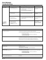
Trouble Shooting
Symptom
No LCD display
Possible Cause
1) mis-wiring of the 12 volt
power to Zone Manager control.
Things to check
1) Verify that +12 v and Gnd are connected to the
proper terrminals of the Zone Manager control and
the COM board. Reference Installlation wiring section
for correct connections
Solution
After disconnecting the power,
correct the wiring problem and
re-cycle power.
2) Check pin connections of Zone Manager to base
plate terminal block while closing the plastic.
+12 volts applied
to CZM at the
correct terminals
and still does not
operate
2) Power not online
1) Check that the units main power is connected. The
main control board should be operating normally
After verifing the wiring to the
Zone Manager control, re-cycle
the unit power.
3) No 12 volts on +12
and GND of terminal block.. .
1) Check the installation of the COM board. Check to
see that the 9 pin connection of the COM board to
main board is correct.
After disconnecting the power,
correct the wiring problem and
re-cycle power.
Verify wiring did not damage
the Zone Manager.
1) Make sure the cable
connections are correct
Change the Zone Manager
control and re-cycle power.
2) The Zone Manager control
is damaged.
System errors
System does not Heat/Cool
1) If diagnostic code is displayed, check diagnostic trouble shooting table.
2) Put the zone manager into "Installation Test" mode and check unit’s LED to blink rapidly.
If the unit’s LED does not blink:
1) Configure unit for the proper zone and re-try "Installation Test".
2) Check communication wiring.
3) Check prime board installation.
3) Select Heat/Cool mode. Adjust the set point so that there is a real heating or cooling request.
Wait for unit’s time guard to expire. If unit does not operate, check unit for errors.
If unit does operate, Check the Zone Managers programming for scheduling errors.
Diagnostic errors
Displayed error "A2"
Temperature sensor error!
Check temperature sensor for damage.
If recycling power does not clear display, replace the Zone Manager.
Displayed error "Cx"
Where x is a number identifying a zone.
Communication error with unit(s) in zone (x)!
1) Put the zone manager into "Installation Test" mode and check unit(s) LED to blink rapidly.
If the units LED does not blink:
1) Configure unit for the proper zone and re-try "COMM" mode.
2) Check communication wiring
3) Check prime board installation.
Displayed error "Fx"
Where x is a number identifying a zone.
Unit(s) in zone (x) has recorded a failure! 1) go to the unit(s) in zone (x) and determine the cause
of the failure.
GB - 16
L010127H14 - 0406
Via R. Sanzio, 9 - 20058 Villasanta (MI) Italy - Tel. 039/3636.1
The manufacturer reserves the right to change any product specifications without notice.
April, 2006.
Printed in Italy