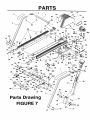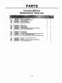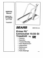
1
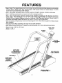
SERVICE
Manual
Model No.:
374.288450
(21-7119)
Treadmill
MADE IN U.S.A.
Prime Fit_"
Concourse 10.55 GI
Treadmill
• Features
by p_p"
• Operation
• Trouble-Shooting
• Parts Replacement
• Adjustments
• Maintenance
• Parts List
• Parts Drawings
08-93
TABLE OF CONTENTS
FEATURES
OPERATION
....................................................
3
...................................................
4
Grounding Instructions ...........................................
Treadmill Operation ..............................................
Incline Adjustment ...............................................
Fitness Computer Operation ......................................
4
4
4
6
Using The Pulse Pickup ..........................................
Operation Trouble-shooting .......................................
7
8
SYSTEM TROUBLE-SHOOTING
..................................
Console .......................................................
Interface Board ................................................
Motor Controller ................................................
9
9
9
9
Motor .........................................................
Speed Control System Trouble-shooting .............................
Speed Control System Wiring Diagram ..............................
9
11
12
PARTS REPLACEMENT
.........................................
Drive Belt, Front Roller, Treadbelt, Treadboard, and rear Roller Replacement
Motor/and
or Flywheel Pulley Replacement .........................
Motor Controller Replacement .....................................
Interface Board Replacement ......................................
Reed Switch Replacement ........................................
13
13
14
14
14
14
Reset Switch Replacement ........................................
Console, Fitness Computer, and / or Power Switch Replacement
Wiring Harness Replacement
.....................................
Incline Lever Replacement ........................................
Gas Cylinder Replacement ........................................
15
15
15
16
16
..........
ADJUSTMENTS
................................................
Treadbelt Adjustment ............................................
Reed Switch Adjustment .........................................
Gas Cylinder Adjustment .........................................
17
17
17
17
MAINTENANCE
18
PARTS
................................................
LIST
Treadmill ......................................................
Console .......................................................
PARTS
19, 20
22
DRAWINGS
Treadmill ......................................................
Console .......................................................
21
23
2
FEATURES
• New Walk-Thru design features a more compact low profile footprint while offering more useable
running space. More track, less wasted space. 990 square inches of usable space; 10-15%
more than most extended profile designs.
• New
Hard Body extruded
frame provides
superior
strength;
• New
Soft Step cushioned
low impact deck with massaging
reduces
vibration
and noise.
effect.
• New Fast Track display features special visual graphics including a 1/4 mile trac and tacho
pulse graph. The extra large 2 1/2" x 4 3/4" LCD id fully programmable
and allows continuous
viewing of time, speed, distance, pulse and calories. Fast Trac also features Fitness Index, a
computer calculated index that allows the user to monitor their fitness level.
• Side mounted
and vibration.
• Includes
2 HP DC motor from G.E. featuring
Power Key (start/stop)
• Gas assist
for easy-to-use
the new Silent Mountsystem
to reduce noise
safe operation.
incline allows you to adjust the percent
grade for a more demanding
• Speed range of 0.5 to 10.0 mph.
• Made In U.S.A.
workout.
FAST TRAC
DISPLAY
POWER
KEY
CUSHIONED
DUAL
HANDRAILS
ADJUSTMENT
LEVER
SOFT STEP
CUSHIONED
LOW IMPACT DECK
(TREADBOARD)
SIDE MOUNTED
2 HP DC MOTOR
TREADBELT
HARDBODY
EXTRUDED
FRAME
(SIDERAILS)
FIGURE 1
OPERATION
• This TREADMILL is intended for home use only.
Be sure your TREADMILL is sitting on a level surface.
The TREADMILL should be plugged into a three prong (grounded) outiet in a 115/120 volt-60 Hz AC circuit separate
from all other appliances - see GROUNDING INSTRUCTIONS.
GROUNDING INSTRUCTIONS
This product must be grounded. If it should malfunction or breakdown, grounding provides a path of least resistance
for electric current to reduce the risk of electric shock. The plug must be plugged into an appropriate outlet that is
properly installed and grounded in accordance with all local codes and ordinances.
WARNING
-- Improper connection of the equipment-grounding
tor can result in a risk of electric shock.
conduc-
Check with a qualified electrician or serviceman if you are in doubt as to whether
the product is properly grounded. Do not modify the plug provided with the product
-- if.it will not fit the outlet, have a proper outlet installed by a qualified electrician.
GROUNDED
OUTLET
GROUNDED
PIN __
This product uses a nominal 120 volt circuit and has a grounding plug that looks
similar to the plug illustrated.
The
use adapter
of an extension
product is not recommended, but if an __,_pL
No plug
should be cord
usedwith
with this
this product.
extension cord is needed, use a short (less than ten feet), heavy gauge (14 gauge
or better) extension cord with a three prong (grounded) plug and receptacle.
TREADMILL
U
:G_ _
OPERATION
NOTE: Before operating your treadmill, become familiar with all operating parts and controls - their location and
function - see FIGURE 3.
To Operate
CA
UTION--To
avoid injury, hold onto HANDRAILS while mounting and dismounting TREADMILL.
Step 1. Place feet on SlDERAILS. Do notatand on TREADBELT. Securely attach POWER KEY CLIP to your
clothing. If you slip or fall while exercising, POWER KEY will pull out of CONSOLE, turning power off.
Step 2.
Insert POWER KEY fully into SLOT in CONSOLE, to turn treadmill's power "ON".
Step 3. Push SPEED CONTROL UP BUTTON to adjust treadmill to slowest speed (0.5 mph).
Step 4. Step onto TREADBELT and begin walking.
Step 5. Push SPEED CONTROL UP BUTTON until you reach your desired speed.
NOTE: The TREADMILL is capable of speeds from around "0.5" to "10" miles per hour. Due to manufacturer
tolerances, the upper and lower speed limits may vary by + or - 0.2 mph. The speed is read from the DISPLAY
in the CONSOLE.
To Stop
Push
SPEED
CONTROL
DOWN
BUTTON
to adjust treadmill to slowest speed (0.5 mph)
Step 1.
Step 2.
Hold onto HANDRAILS
and place feet on SIDERAILS.
Step 3.
Push STOP / PAUSE BUTTON.
Step 4.
Remove POWER KEY, to turn treadmill's power "OFF".
To Adjust Incline
CA
UTION--
RAISING
....
LOWERING
POWER KEY must be removed before incline adjustments are made.
Dismount the treadmill, pull up the INCLINE LEVER and release when the treadmill reaches the
desired incline angle.
- - - Mount the treadmill, pull up the INCLINE LEVER and release when the treadmill reaches the
desired incline angle.
4
OPERATION
FAST TRAC
FITNESS COMPUTER
SPEED CONTROL
UP/DOWN
BUTTONS
DISPLAY
\,,i
BUTTONS
SELECT
J
INCLINE
LEVER
STOP/PAUSE
BU1-FON
POWER
KEY
CONSOLE
\
POWER
FITNESS
INDEX
BUTTON
CLIP
KEY
_
OPERATOR'S
VIEW
of CONSOLE
HANDRAILS
TREADBELT
SlDERAILS
TREADBELT
ADJUSTMENT
SCREWS
FIGURE 2
5
OPERATION
FITNESS COMPUTER
The FITNESS COMPUTER is designed to provide five
functions displayed automatically, four programmable
functions and a fitness index function.
Automatically
Displayed Functions
1. TIME:
Counts up from 0:00.
2. SPEED:
Displays speed in miles per hour.
3. DISTANCE
a. MILES:
Counts up from 0 in total miles.
b. LAPS:
Counts up from 0 in total laps.
(1 lap = 114 mile)
4. CALORIES:
PULSE:
Counts up from 0.
KEY
Displays your heart rate.
Programmable
Functions
1. TIME:
Time can be preset from 0:00 to
99.00 in one minute increments.
2.
DISTANCE:
Distance can be preset from 0 miles
(0 laps) to 49 3/4 miles (199 laps) in
1/4 mile (1 lap) increments.
3. CALORIES:
Calories can be preset from O to 990
in 10 calorie increments.
4. PULSE
TARGET:
A pulse target can be preset from 90
to 180 in 1 beat per minute increments or "--" for pulse display only.
SELECT
BUTTON
FITNESS
INDEX
BUTTON
UP/DOWN
BUTTONS
The FITNESS INDEX button tracks your fitness level
with computer calculated fitness rating.
I
Insert POWER KEY. Functions will start counting when
the treadmill speed is greater than O mph.
• Refer to TRAINING CHART on page 15 in owner's
manual for your recommened PULSE TARGET.
• Refer to "USING THE PULSE EARCLIP" section and
attach eamlip as directed,
Press SELECT BUTrON until only display area of the
desired function to beprogramed (TIME,
DISTANCE or CALORIES) is displayed.
Press SELECT
Press UP or DOWN BUTTON until desired numberis
reached. Wait 4 seconds. When treadmill
speed is greater than 0 mph, desired pro_amed function (TIME,
DISTANCE or
LORIES) will start counting.
Press UP or DOWN BUTTON : until desired PULSE
TARGET
set point is
reached.
1 LAP
Ij
BUTTON: until "PULSE" appears in
pulse display area.
START I FINISH
POINT
10 Beats Per
Minute Below
Pulse Target
Set Point
10 Bests Per
Minute Above
Pulse Target
I
Pulse Target
!lllllillilW
,.LAP---j
m-- ,LAP
_
\_"
1/2 LAP
1 LAP = 1/4 MILE
6
v
/
PULSE
BELOW
TARGET ZONE
i
_
\_"
v
PULSE
WITHIN
TARGETZONE
/
/
\_
\_"
v
PULSE
ABOVE
TARGETZONE
/
/
OPERATION
The FITNESS INDEX button tracks your fitness level
with computer calculated fitness rating. The Fitness
Computer will calculate your fitness rating from 0 (Poor)
to 10 (Good).
Your level of fitness is determined by your pulse rate.
As you fitness level increases you will find that you will
need to walk or jog faster to stay in the pulse range you
have chosen. The FITNESS INDEX button gives you
feedback to your increasing fitness level.
NOTE: You must stay consistant in your workouts in
order to get an accurate and consistant fitness rating.
Refer to "USING THE PULSE EARCLIP" section and
attach earclip as directed.
After completing your workout, remain still with earclip
attached.
Press FITNESS
INDEX
DETAIL "A"
button. 0:60 will appear in
TIME display area. Time will
count down to 0:00 and Fitness Computer will calculate your fitness rating from
Oto 10.
-.
-..
EARCLIP
CABLE
/
\\
\
COLLAR
""
"\
Using The PULSE EARCLIP
/
/:/
CA UTION
STRAIN RELIEF CLIP
-- This pulse earclip is not a medical device. Readings may not always be accurate. Best
readings may be obtained in a still, relaxed position.
DETAIL "B"
IMPORTANT--
When exercising in a vigorous manner the erratic movement of the PULSE
EARCLIP or CABLE may cause the "P" to appear in the
PULSE window indicating incorrect pulse readings. Try
to keep the PULSE EARCLIP and CA BLE from unecessary movement when exercising.
/._- _-.
//
//
-, •
1. Insert EARCLIP PLUG into EARCLIP RECEPTACLE
on back of CONSOLE - see DETAIL "A".
2. Attach STRAIN RELIEF CLIP to your cellar or other
piece of clothing - see DETAIL "B".
]Y..Q.TJ_:
EARCLIP CABLE must not be aflowed to be
in a strain.
/_:
EARCLIP
3. Massage EARLOBE to increase circulation.
EARLOBE
4. Attach EARCLIP to EARLOBE in a vertical position see DETAIL "C".
DETAIL "C"
5. When exercise has been completed remove EARCLIP from earlobe and clip it to EARCLIP CABLE.
7
OPERATION
OPERATION
Treadmill Will Not Start.
1.
il.
TROUBLE-SHOOTING
Plug Into Three Prong (grounded)
115/120 Volt-60 Hz AC Outlet - See
Treadmill Grounding.
! Not Plugged In.
i2.[
3.
House Circuit Breaker
Tripped.
Treadmill Reset Switch
Tripped.
Reset Or Replace Fuse.
Reset Treadmill Reset Switch.
4.
Unit Plugged Into Insufficient
Extension Cord.
Plug Directly Into Wall Outlet Or
Use Short (less Than Ten Feet),
Heavy Gauge (t4 Gauge Or Better)
Extension Cord.
5.
Inadequate Voltage At Outlet.
Have Qualified Electrician Check
Voltage.
Treadbelt Does Not Run In
Center Of Roller.
1.
Treadbelt Tension Not Even
Across The Treadbelt.
See - "Treadbelt Adjustment" on
page 17.
3.
Treadbelt Slips While In Use.
1.
Treadbelt Tension Too Light.
See - "Treadbelt Adjustment" on
page 17.
4.
Treadbelt Hesitates When
Stepped On.
1.
Insufficient Lubricant On
Treadbelt.
See "Maintenance"
5.
Treadmill Makes "Rumbling"
Noise.
1.
Treadbelt Tensioned Too
High.
Loosen Treadbelt Ad ustment Bolts
Till Noise Ceases But Treadbe t
Does Not Slip While In Use.
Treadmill Makes "whining"
Noise.
1.
Walking Too Close To The
Edge Of Treadbelt.
Bring Stride Back Towards Center
Of Treadbelt.
7.
Treadmill Is Difficult To Roll.
1.
Treadmill On Thick Carpeting.
Move To Hard Surface Or Low Cut
Carpeting.
8.
Black Particles Collecting
Under Treadmill.
1.
Drive Belt Is Breaking In.
Vacuum Under Treadmill
Periodically
2.
6.
on page 18.
9.
No Display On Fitness
Computer in Console.
1.
Treadmill Not Plugged In
And Power Key Not Inserted
Into Console.
Plug Into Three Prong (grounded)
115/120 Volt-60 Hz AC Outlet - See
Treadmill Grounding. Insert Power
Key. Adjust Treadbelt Speed
greater than 0 mph.
10.
Fitness Computer Does Not
Display Speed Or Distance.
1.
Reed Switch Not Aligned
Properly.
See -"Reed Switch Adjustment" on
page 17.
11.
Fitness Computer Shuts Off.
1.
Magnet Damaged Or Missing
From Pulley on t-ront Roller.
Replace Magnet.
2.
Reed Switch Not Working
Properly.
Fitness Computer Not
Working Properly.
Replace Reed Switch.
! 3.
[
12.
No Pulse Displayed On
Fitness Computer.
21
Into Console.
Pulse Earclip Not Plugged
Pulse Earclip Not Properly
Attached To Earlobe.
3.
Pulse Earclip In Direct
Sunlight
4.
Pulse Earclip Is Moving
Around Too Much.
i 3. I Replace Fitness Computer.
rt 1. ! Plug Pulse Earclip Into Back of
i Console.
2.
Circulation And Reattach Pulse
Massage Earlobe To Increase
Earclip.- See "Using The Pulse
Earclip
3. I Place
Earclip"Pulse
On Page
7. On Earlobe
.
I Away From Direct Sunlight.
I 4. Use Strain Relief Clip And Try Not
I
To
Move "B"
Head
DETAIL
On Erratically
Page 7. - See
IF OTHER PROBLEMS ARE ENCOUNTERED OR ANY PROBLEMS CAN NOT BE CORRECTED,
CALL OUR SERVICE DEPARTMENT TOLL FREE AT 1-800-473-7247.
8
PLEASE
TROUBLESHOOTING
Console and Motor System
Four components make up the console and motor system; FAST TRAC FITNESS COMPUTER, mounted on the
console, INTERFACE BOARD, mounted on the bottom motor cover, MOTOR CONTROLLER and MOTOR mounted
to the front right rail.
Console
The CONSOLE contains the FAST TRAC FITNESS COMPUTER which controls the speed and elevation of the
treadmill. It also displays time, speed, distance (miles and laps), calories, and pulse.
The time will display from 0:00 to 99:00 in one minute increments. The speed will read between .5 and 10.0 at .1 MPH.
The distance is indicated in miles (0 to 49 3/4) and laps (0 to 199). The calories will be displayed from 0 to 990 in 10
calorie increments.The pulse displays your heart rate from 90 to 180 in 1 beat per minute increments. The time,
distance, calories, and pulse desired can be programmed into the fitness computer.
Interface
Board
The interface board is an electronic circuit board mounted to the bottom motor cover- see FIGURE 3. With the treadmill
plugged in and the power key inserted the DC voltage from PI to N on the interface board should be 13.6 VDC. The
voltage from P2 to N will vary with the speed;
0
MPH - 0 VDC
.5
MPH - .68 VDC
10.0 MPH - 12.3 VDC
The voltage across the capacitor, Cl, should be 9.56 VDC. When the treadmill is running at .5 MPH the motor should
maintain 250 RPM, at 10.0 MPH the motor should maintain 5200 RPM.
Motor Controller
The motor controller is an electronic circuit board mounted to the right rail in front of the motor - see FIGURE 4. From
a grounded wall outlet the motor controller receives 120 VAC and converts it to variable DC 0 to 90 V. The monitor
and interface board adjust the output of the motor controller from 0 to 90 volts. The motor controller senses the motor
speed by the tachometer. The tachometer on the motor tells the motor controller its speed. If a load is placed on the
treadbelt the motor controller compares the set point of the speed control to the tachometer and makes adjustments
to the DC output voltage to the motor keeping the treadbelt running at a fixed speed. For example, the output voltage
will be 9.5 volts at .5 MPH, as a person steps on the treadbelt the output voltage increases to compensate for the
extra motor loading, keeping the treadbelt running at .5 MPH.
Motor
This treadmill uses a 2 HP DC motor - see FIGURE 5. When the voltage to a DC motor is changed the speed will
vary accordingly. The motor receives 0-90 VDC from the motor controller. The voltage from M1 to M2 while the treadmill
is running at 10.0 MPH should not exceed 90 VDC and the should be turning at 5200 RPM. The motor has an integral
tachometer which tells the motor controller the motor's speed. The tachometer consists of a coil of wire inside a plastic
housing. A permanent magnet mounted to the motor, behind the fan, rotates inside the tachometer coil generating a
low voltage, proportional to the motor speed.
.66 VAC - 250 RPM
9.40 VAC - 5200 RPM
The tachometer coil should be 300 ohms 25 ohms.
Note: The tachometer can be measured with an ohmmeter only when disconnected from the motor controller.
The winding resistance should be very low, approximately 1 ohm. Test each winding in the armature (the rotating part
inside the motor) by slowly rotating the motor shaft 1 complete revolution. All windings should be less than 2 ohms.
Note: The windings of the motor can be measured with an ohmmeter only when disconnected from the motor
controller.
9
TROUBLESHOOTING
INTERFACE
BOARD
\
MOTOR
CONTROLLER
FIGURE 4
FIGURE 3
2 HP DC
MOTOR
SHAFT
FAN
r
TACHOMETER
WIRESTO
CONTROLLER
,' TACHOMETER
POWER WIRES
TO M1 AND M2 ON
MOTOR CONTROLLER
GROUND WIRE
(GREEN)
TO FRAME
FIGURE 5
10
TROUBLESHOOTING
SPEED CONTROL
EB-O-B-LEM
1.
SYSTEM
TROUBLE-SHOOTING
:
Treadmill Will Not Start.
1.
Verify Wall Outlet Has
Proper Voltage.
1, ' Reset Circuit Breaker or Replace
Fuse.
2. i Verify Wall Outlet Is Properly
Grounded.
,_2. i Ground Walt Outlet.
i
3. i Check Reset Switch.
i 3. i Replace Reset Switch.
Check On/Off Switch. Verify
Power Key Activates On/Off
Switch.
2.
3.
Replace On/Off Switch.
5.
Verify Motor Controller Has
120 VAC, Line To Neutral
And Line To Frame.
5.
Reset Reset Switch and Insert
Power Key Fully•
6,
Check For Open Tachometer
Circuit
6.
Replace Motor.
120 VAC Not Present at
Motor Controller.
Remove Wall Plug From
Wall Outlet. Check Continuity
From Line Terminal of Plug
To Line Terminal Of Motor
Controller. Check Continuity
i Of Neutral Terminal of Plug
To Neutral Terminal of Motor
I Controller.
120 VAC at Motor Controller,
But Motor Does Not Run.
1.
I Terminals
Check Voltage
On M2.
Motor
M1 And
•
i 17 VDC At Low Speed.
70 VDC At High Speed.
I
Repair Or Replace Loose Wiring /
Wire Terminals. Repair Or Replace
Reset Switch / On/Off Switch.
I, 1. ' Check Motor Wiring.
Replace Motor.
i
I
i
2.
i2. '_Check For Open Tachometer
Replace Motor.
i Circuit
j3• j
4.
Motor Runs Extremely Fast
(Greater Than 90 VDC, M1
To M2).
[1.
J
12.
3.
Replace Motor Control Board.
Motor Controller Bad.
1.
Replace Motor Controller
Capactor Damaged On
Interface Board
1. i Replace Interface Board
Reed Switch gives no
reading.
1
a. Align Reed Switch.
• '=b. Replace Reed Switch
Shorted
Triac OnMotor
Control Board.
Flickering Monitor
i 1.
I
7.
No Distance Indicated
! 1.
i
No High Speed / Low Speed
Works
Replace Tachometer Magnet
/Replace Fan.
Check For Damaged /
1.
P
2.
Cheek
For Missing
Tachometer
Magnet /
_ Missing Fan.
I
8.
i
l
6.
Tighten Fan.
I
! 1. x Replace Motor.
i Tachometer.
Check For Shorted
! 3.
Treadmill Has No Safety
Start.
i 3.
r
I
l
5°
Check For Loose Fan.
! 1. j Belt Tension Incorrect.
r
[ 2. i Lubrication Incorrect
! 3. _ Check P2 To N On Interface
! Board (12.3 VDC At Max
I
'1 Speed).
14. _
1 70 Volts From M1 To M2 At
I Max Speed.
'
i a.) Voltage OK
!
b.) Voltage Bad
11
l
I 1. } Adjust Belt Tension.
2. a.) Add Lubrication If Feels Dry.
b.) Wipe Down If Dripping Wet.
3.
: 4.
Replace Interface Board.
a) Replace Motor
b.) Replace Motor Controller
TROUBLESHOOTING
SPEED CONTROL SYSTEM TROUBLE-SHOOTING
,
9.
Console On But Won't Start.
Set Speed To 6.0 MPH To
Diagnos Cause.
.
Volts From M1 to M2.
£._.BBE.C_T_IQN
t.
_:/Voltag
VoltageeOK
Bad
2.
cont.
a.) Replace Motor
lb.) Check Interface Board P2 - N
P2 - N Voltage Between 0.6
and 13.0.
2.
b)a?CheckReplacep1M°t°rto
N Controller
_:}G
Badood
3.
P1 To N Voltage 13.6.
_:I
Good
Bad
a.) Replace Interface Board.
b.) Replace Motor Controller.
CONSOLE
]
POWER SWITCH
FAST TRAC DISPLAY
FITNESS
COMPUTER
NO ¢_t_CTl(_l
(OP'f tONaL "f_])-'_
CIRCUIT
BREAKER
INTERFACE
BOARD
(TLP2)
_.
16 AVG
I
PLUG
BROWN
SPEED CONTROL
SYSTEM WIRING
FIGURE 6
12
DIAGRAM
PARTS REPLACEMENT
PARTS REMOVAL AND REPLACEMENT
DANGER:
Unplug
the TREADMILL
from the outlet to reduce the risk of an electric shock.
Drive Belt (36), Front Roller (13), Treadbelt
Roller (14) Replacement
(12), Treadboard
(11), And/or Rear
Step 1. Remove MOTOR COVER (43).
Step 2. Elevate FRONT end of TREADMILL
using INCLINE LEVER (46e) on CONSOLE (46)
Step 3. Remove two BOLTS (55) attaching LEFT HANDRAIL to LEFT SIDERAIL (9).
Step 4. Remove REAR ROLLER ADJUSTMENT BOLTS (58), REAR END CAPS (15 RIGHT & 16 LEFT), and
REAR GUARDS (18 RIGHT & 19 LEFT).
Step 5. Loosen LOCKNUT (69) on J-BOLT (53) to release DRIVE BELT (36) tension.
Step 6. Remove LOCKNUT (69) and BOLT (59) holding GAS CYLINDER (26) to INCLINE ASSEMBLY
Step 7. Remove INCLINE ASSEMBLY
(22).
(22).
Step 8. Remove four BOLTS (55) attaching
INCLINE BRACE.
INCLINE BRACE(21) to SIDERAILS (9 LEFT & 10 RIGHT). Remove
Step 9. Remove REAR BOLTS (55) holding INCLINE PIVOT BRACKETS (30) to SIDERAILS (9 LEFT & 10 RIGHT).
NOTE: The INCLINE PIVOT BRACKET does not need to be removed, just the REAR BOLTS.
Step 10. Remove BOLTS (56) attaching TREADBOARD
to SIDERAILS (9 LEFT & 10 RIGHT).
Step 11. Remove the FRONT two SCREWS (46) from BOTTOM MOTOR COVER(44) / PULLEY COVER (45) and
remove PULLEY COVER.
Step 12. Remove BOLTS (56) from FRONT ROLLER (13).
Step 13. Remove LEFT SIDERAIL (9).
_LO_TJ_:
Slide LEFT RAIL off TREADBOARD.
Step 14. To replace the FRONT ROLLER (13), remove FRONT ROLLER and replace. Make sure DRIVE BELT is
on before reassembling.
JY_Q.T_E:
It is not necessary to remove REAR ROLLER, TREADBOARD, or TREADBELT.
Step 15. To replace DRIVE BELT (36), remove FRONT ROLLER (13) and DRIVE BELT (36). Replace DRIVE BELT
and reinstall FRONT ROLLER.
blO_T_.E:
It is not necessary to remove REAR ROLLER, TREADBEL T, or TREADBOARD.
Step 16. To replace TREADBELT (12), slide old TREADBELT off TREADBOARD (11). Replace with new TREADBELT.
It is not necessary to remove TREADBOARD from RIGHT RAIL, or the FRONT and REAR
ROLLERS.
Step 17. To replace TREADBOARD (11), remove the FRONT ROLLER (13), REAR ROLLER (14), and TREADBELT
(12). Separate the TREADBOARD and RIGHT SIDERAIL (10). Replace TREADBOARD.
NOTE: Make sure the BELT GUIDE BRACKETS are installed on the TREADBOARD.
Step 18. To replace REAR ROLLER (14), remove REAR ROLLER and replace.
]Y..O_.T_:
It is not necessary to remove FRONT ROLLER (13), TREADBEL T (12) or TREADBOARD
(11 ).
Step 19. Reassembe in reverse order: make sure J-BOLT (53) has been tightened and retention the TREADBELT
(12) - see "ADJUSTMENTS" section for proper method of tensioning TREADBELT.
bL(2T_E:When reassembling, make sure the FRONT ROLLER (13) and REAR ROLLER (14) are fined up
with the TREADBOARD (11) slot in theLEFT S/DERAIL before installing LEFT S/DERAIL. Also,
make sure the DRIVE BELT (36) is on the FRONT ROLLER (13).
13
PARTS REPLACEMENT
Motor (35b) And Or Flywheel
Pulley (35c) Replacement
Step 1. Remove MOTOR COVER (43).
Step 2. Loosen LOCKNUT(69)
on J-BOLT (53) to remove DRIVE BELT (36) from FLYWHEEL PULLEY (35c).
Step 3. To replace the FLYWHEEL PULLEY (35c), remove FLYWHEEL PULLEY from MOTOR (35c) by holding
the motor shaft with a STANDARD screw driver and turning the flywheel clockwise. Install new Flywheel
Pulley On Motor
Step 4. Remove Motor wires from MOTOR CONTROLLER
Step 5. Remove two MOUNTING
(42) and GREEN wire on RIGHT SIDERAIL (10).
STRAPS (35d) attaching MOTOR (35b) to MOTOR MOUNT (35a).
Step 6. Remove MOTOR (35b) with FLYWHEEL PULLEY (35c).
Step 7. Reattach MOTOR (35b) and FLYWHEEL PULLEY (35c) in reverse order usingSPEED CONTROL SYSTEM
WIRING DIAGRAM - see page 12 to assure proper wiring. Make sure the GROUND WIRES (GREEN) are
attached to the RIGHT SIDERAIL (10) and LOCKWASHER (62) is against the SIDERAIL.
Motor Controller
(42) Replacement
Step 1. Remove MOTOR COVER (43).
Step 2. Remove wires, one at a time to assure proper attachment, and install onto new MOTOR CONTROLLER
(42). Refer to SPEED CONTROL SYSTEM WIRING DIAGRAM - see page 12 to assure proper wiring.
Step 3. Remove two SCREWS (64) attaching MOTOR CONTROLLER
Step 4. Reattach MOTOR CONTROLLER
(42) to RIGHT SIDERAIL (10).
(42) to RIGHT SIDERAIL (10) with two SCREWS (64).
Step 5. Reattach MOTOR COVER (43).
Interface
Board (73) Replacement
Step 1. Remove MOTOR COVER (43).
Step 2. Remove wires, one at a time to assure proper attachment, and install onto new INTERFACE BOARD (73).
Refer to SPEED CONTROL SYSTEM WIRING DIAGRAM - see page 12 to assure proper wiring.
Step 3. Remove CIRCUIT
COVER (44).
BOARD SUPPORTS
Step 4. Attach new INTERFACE
PORTS (54).
(54) attaching INTERFACE
BOARD (73) to BO]-rOM
MOTOR
BOARD (73) to BOTTOM MOTOR COVER (44) using CIRCUIT BOARD SUP-
Step 5. Reattach MOTOR COVER (43).
Reed Switch (23) Replacement
Step 1. Remove MOTOR COVER (43).
Step 2. Remove SCREW (64) attaching REED SWITCH (23) to RIGHT SIDERAIL (10).
Step 3. Unplug CONNECTOR
END of REED SWITCH (23) from INTERFACE BOARD (73).
Step 4. Route new REED SWITCH (23) wire in same location as old REED SWITCH wire.
Step 5. Install REED SWITCH (23) to RIGHT SIDERAIL (10) with SCREW (64) and TOOTH LOCKWASHER (62).
NOTE: Make sure TOOTH LOCKWASHER is on SIDERAIL side.
Step 6. Plug CONNECTER
END of REED SWITCH (23) into INTERFACE BOARD (73).
Step 7. Adjust REED SWITCH (23) - see "ADJUSTMENT" section for proper method of adjusting REED SWITCH.
Step 8. Reattach MOTOR COVER.
14
PARTS REPLACEMENT
Reset Switch
(33) Replacement
Step 1. Remove MOTOR COVER (43).
Step 2. Remove wires from RESET SWITCH (33), one at a time to ensure proper attachment and install on new
RESET SWITCH. Refer to SPEED CONTROL SYSTEM WIRING DIAGRAM on page 12 if necessary.
Step 3. Remove RESET SWITCH (33) from POWER CORD BRACKET (31).
Step 4. Reinsert RESET SWITCH (33) into POWER CORD BRACKET (31) and attach MOTOR COVER (43).
Console
(46), Fitness Computer
(46a), And/Or Power Switch Replacement
Step 1. Remove CONSOLE attaching SCREWS (63).
Step 2. Slip CONSOLE (46) out of CONSOLE TUBE (40).
Step 3. Remove four SCREWS(46o) and one SCREW (46m) attaching FITNESS COMPUTER (46a) to CONSOLE
BOTTOM (46b).
Step 4. To replace FITNESS COMPUTER (46a), unplug FITNESS COMPUTER
(46g) and plug in new FITNESS COMPUTER.
NOTE: Rep/ace any monitor casing needed.
(46a) from WIRING HARNESS
Step 5. To replace POWER SWITCH (46k), remove wires from POWER SWITCH and attaching SCREW (461),
snap POWER SWITCH out of the CONSOLE BOI-rOM (46b) and replace with new POWER SWITCH.
Step 6. Reassembly
Wiring Harness
in reverse order - see SPEED CONTROL SYSTEM WIRING DIAGRAM if necessary.
(46g) Replacement
Step 1. Remove MOTOR COVER (43).
Step 2. Remove CONSOLE (46) - see CONSOLEAND/OR POWER SWITCH REPLACEMENT.
NOTE: Steps 2 through 6 required for UPPER WIRING HARNESS replacement.
Step 3. Remove BLACK wires from INTERFACE BOARD (73).
Step 4. Remove BROWN wire from RESET SWITCH (31).
Step 5.
Remove LARGE CONNECTOR
from INTERFACE BOARD(73),
Step 6. Pull UPPER WIRING HARNESS (64g) from CONSOLE TUBE (40).
Step 7. Remove SMALL CONNECTOR from INTERFACE BOARD (73).
Steps 7 through 12 required for LOWER WIRING HARNESS replacement.
Step 8. Remove GRAY and BLUE wire from MOTOR CONTROLLER
(42).
Step 9. Remove REED SWITCH (23) - see REED SWITCH REPLACEMENT.
Step 10. Remove WHITE wires from INTERFACE BOARD (73).
Step 11. Remove WHITE wire from MOTOR CONTROLLER
(42).
Step 12. Remove LOWER WIRING HARNESS.
Step 13. Replace WIRING HARNESSES and reinstall in reverse order. Refer to SPEED CONTROL
WIRING DIAGRAM to assure proper wiring.
15
SYSTEM
PARTS REPLACEMENT
Incline Lever (46e) Replacement
Step 1. Remove two SCREWS (63) at top of CONSOLE TUBE (40).
Step 2. Remove one SCREW (460) on lower rear side of CONSOLE BOTTOM (46b).
Step 3. Pull CONSOLE (46) from CONSOLE TUBE (40) and remove two SCREWS (46n) and remove LOWER
CONTROL PANEL (46d) from CONSOLE BOTTOM (46b).
Step 4. Reinsert CONSOLE (46) into CONSOLE TUBE (40) for convenience.
Step 5. Remove two SCREWS (46n) attaching INCLINE BRACKET (46f) to back side of LOWER CONTROL PANEL
(46d).
Step 6. Remove INCLINE LEVER (46e) from PIVOT SLOTS in back side of LOWER CONTROL PANEL (46d).
Step 7. Detach INCLINE LEVER (46e) from INCLINE CABLE (46j) by sliding CABLE END of INCLINE CABLE into
upper hole in INCLINE LEVER and pulling through.
Step 8. Reassemble CONSOLE (46) using REPLACEMENT
in reverse order.
INCLINE LEVER (46e) by following steps 1 through 8
Gas Cylinder (26) Replacement
Step 1. Hold INNER
ACTIVATING
CABLE of INCLINE CABLE (46j) at GAS CYLINDER (26) with pliers. Press down on
LEVER and disconnect INNER CABLE from ACTIVATING LEVER.
Step 2. Pull OUTER CABLE of INCLINE CABLE (46j) straight up with pliers to disconnect INCLINE CABLE from
ACTIVATING LEVER.
Step 3. Remove front BOLT (59) and LOCKNUT (69) attaching GAS CYLINDER (26) to INCLINE FRAME (22).
Step 4. Remove rear BOLT (60) and LOCKNUT (69) attaching GAS CYLINDER (26) to INCLINE BRACE (21).
Step 5. Replace GAS CYLINDER (26) in reverse order.
INNER
CABLE
END OF THREADED SHAFT TO
BE FLUSH WITH FLAT SURFACE
OF ACTUATING LEVER AS
I o _
SHOWN.
_E
INCLINE
ABL
OUTER
CABLE
ACTUATING
LEVER
46J
PIVOT
BRACKET
GAS CYLINDER
ASSEMBLY
16
ADJUSTMENTS
Treadbelt
Adjustment
The TREADBELT (12) has been factory pre-adjusted. However,
ifthe TREADBELT shifts
to one side or the other, follow these steps to readjust it - see FIGURE 2. Adjust
TREADBELT ADJUSTMENT SCREW (56) by using the ALLEN WRENCH (70) provided.
ALLEN WRENCH
Step 1. If TREADBELT has moved to right,tighten right TREADBELT ADJUSTMENT SCREW 1/2 turn using ALLEN
WRENCH, while TREADMILL is running and no one is on it. The TREADBELT should move towards left.
Step 2. Let TREADMILL
run several turns of TREADBELT and note any sideways movement.
Step 3. If only a small amount of change occurred, loosen left TREADBELT ADJUSTMENT SCREW 1/2 turn using
ALLEN WRENCH.
Step 4. Repeat step 2.
Step 5. Repeat steps 1 through 4 until TREADBELT is centered and remains there during use. If TREADBELT has
moved to LEFT, follow steps 1-4 but start with LEFT side.
NOTE: ff TREADBEL T is slipping it will be necessary to tighten both TREADBEL T ADJUSTMENT SCREW
until slipping has stopped. It may then be necessary to repeat steps 1 through 4 for alignment.
_D_L_L_'.
DO NOT OVERTIGHTEN TREADBEL 7".Overtightening is denoted by curling of
the edges of the TREADBEL T.
Reed Switch Adjustment
If the CONSOLE (46) does not display SPEED or DISTANCE the REED
SWITCH (23) and MAGNET on the FRONT ROLLER (13) may be misaligned see FIGURE 7. Follow these steps to check and realign it:
Step 1. _L__Unplug
FRONT
ROLLER
MAGNET
/
118"
I
the TREADMILL to reduce the risk of an
WIRE
electric shock.
F
Step 2, Remove MOTOR COVER (43) - see FIGURE 7.
Step 3. Check spacing and alignment between MAGNET on right side of
FRONT ROLLER (13) and REED SWITCH (23) on the RIGHT SIDERAIL (10) - see DETAIL. The spacing must be 1/8" and the edge of
the REED SWITCH must be aligned with the center of the MAGNET.
Loosen SCREW (64) and move REED SWITCH. Then Retighten
SCREW.
NOTE: 1/8" is equal to the thickness of two pennies.
Step 4. Reattach MOTOR COVER (43) - see FIGURE 7.
Step 5. Plug-in the TREADMILL
SOLE.
0
REED/J
SWITCH
RIGHT
SlDERAIL
_----
/
DETAIL
and check SPEED or DISTANCE on CON-
Gas Cylinder Adjustment
Step 1. Remove front BOLT (59) and LOCKNUT (69) attaching GAS CYLINDER (26) to INCLINE FRAME (22).
Step 2. Loosen JAM NUT on GAS CYLINDER (26) holding ACTUATING LEVER to PIVOT BRACKET.
Step 3. Rotate GAS CYLINDER
(26) 360 ° clockwise.
Step 4. Tighten JAM NUT on GAS CYLINDER (26) to hold ACTUATING LEVER to PIVOT BRACKET.
Step 5. Reattach GAS CYLINDER (26) to INCLINE FRAME (22) using BOLT (59) and LOCKNUT (69).
Step 6. Test unit for proper incline operation. If unit does not raise and lower properly repeat Steps 1-5.
17
MAINTENANCE
Your CONCOURSE TREADMILL should require little actual maintenance other than periodically applying LUBRICANT under the TREADBELT. Adequate lubrication of the TREADBOARD surface under the TREADBELT will
ensure superior performance and extend its life expectancy.
How To Check TREADBELT
For Proper Lubrication:
1.
Lift one side of TREADBELT
and feel the top surface of the TREADBOARD.
2.
If the surface is wet (slick) to the touch, then no further lubrication is required.
3.
If the surface is dry to the touch, apply one packet of LUBRICANT.
How to apply LUBRICANT:
1.
Lift one side of the TREADBELT.
2.
Pour one entire LUBRICANT
BOARD.
3.
Walk on TREADMILL
packet under the center of the TREADBELT
on the top surface of the TREAD-
at slow speed for 3 to 5 minutes to evenly distribute LUBRICANT.
NOTE: Do not over-lubricate TREADBOARD. Excess LUBRICANT may come out from underthe
excess LUBRICANT on the TREADBOARD should be wiped off.
TREADBEL T. Any
Lubrication Schedule:
If the TREADMILL is used at low speeds, the TREADBELT will not need to be lubricated as frequently; while high
speed use may require more frequent lubrication. If the TREADBELT does not maintain speed during use or hesitates,
lubrication may be required. The following lubrication schedule is only a guideline based on average TREADMILL
use:
1.
After the first 25 hours of use (2-3 months), apply one LUBRICANT packet.
2.
Every 50 hours of use (5-8 months), apply an additional LUBRICANT packet.
Two LUBRICANT packets are included with the TREADMILL.
ten, using the form below.
LUBRICANT
Additional LUBRICANT can be ordered in packs of
ORDER FORM
10 packets - 1/3oz ea.
NAME:
MAIL TO:
Diversified Products Corporation
P.O. Box 100
Openka, AI 36803
Attn.: Customer Service
ADDRESS:
Include check or money order for $9.95. Checks should be made out to Diversified Products.
AMOUNT ENCLOSED:
18
PARTS
Replacement Parts List
1
2
3
4
5
04043200
04043500
30464216
31294116
38375316
Handrail
Handrail Bracket
Irail
1
1
1
1
1
6
7
8
9
10
09169300
30464516
31294216
34026910
34026810
Elbow Connector
Front Handrail
Front Handrail Bracket
Left Siderail.
Right Siderail
1
1
1
1
1
11
12
13
14
15
39378500
09172300
39393700
39386200
09168800
Treadboard
Tread Belt
Front Roller
Rear Roller
Left Rear End Cap
1
1
1
1
1
16
17
18
19
20
09168900
09169000
09169100
09170200
31292710
Right Rear End Cap
Left Front End Cap
Left Rear Guard
Right Rear & Left Front Guard
SQuareWasher
1
1
1
2
2
21
22
22a
22b
22c
38356816
39405300
38373816
09076600
31184500
Incline Brace
Incline (Assembly)
Incline Frame
Wheel
Rod
1
1
1
2
1
22d
22e
22f
25018900
39152200
25014600
34029910
21027700
5/16" Pushnut
Roller
5/16" Locknut
Incline Rail
#10 x 5/8" Long Machine Screw
2
2
2
2
4
22i
23
24
25
26
25026000
37046100
62444100
34027810
39388300
t10 Capnut
:leed Switch
Operation Decal
Incline Rail
Gas Cylinder w/Pivot Bracket
4
1
1
2
1
27
28
28a
28b
29
39152200
39393800
38358716
02064000
31299710
=loller
=oot (Assembly)
=oot
Foot Cap
Spacer Plate
2
2
2
2
2
30
31
32
33
34
31299616
31291816
39368900
37024500
39379900
Incline Pivot Bracket
Power Cord Bracket
Power Cord
Reset Switch 10 amp
Motor Mount Bracket (Assembly)
2
1
1
1
1
34a
34b
35
35a
35b
31292510
20016000
39379300
38356510
37041200
Motor
#10 x
Motor
Motor
Motor
1
2
1
1
1
Mount Bracket
1/2" Sheet Metal Screws
/ Motor Mount (Assembly)
Mount
19
PARTS
Replacement
Parts List cont.
35c
35d
36
37
38
33021010
39195600
09175300
31292616
31291710
Flywheel
Mounting Strap
Drive Belt
Console Tube Bracket
Support Bracket
1
2
1
1
1
39
40
41
42
43
31292410
30464116
62447600
37043200
09165100
Bracket
Console Tube
Console Tube Label
Controller 10 amp
Motor Cover
1
1
1
1
1
44
45
46
47
48
31295416
09177200
39394000
09179500
09169400
uottom Motor (..;over
Pulley Cover
Console (Assembly)
Grommet
Flanged Bushing
1
1
1
2
1
49
5O
51
52
53
37040100
29452200
29447200
29449800
23020800
Strain Relief Bushing
Spdng
"U" Clip
S" Clip
"J" Bolt"
1
1
1
1
1
54
55
56
57
58
09177400
23021000
23020900
23021100
22026700
Circuit Board Support
1/4" x 3/4" Long Flex Washer Head Screw
1/4" x 1 1/2" Long Hex Washer Head Screw
1/4" x 2 112"Long Hex Washer Head Screw
1/4" x 3" Long Button Socket Head Cap Screw
4
22
8
4
2
59
6O
61
62
63
22020000
22018100
22027300
26009700
20016000
5/16" x 1 1/4" Long Hex Head Bolt
5/16. x 2_ Long Hex Head Bolt
5/16 x 4 Long Hex Head Bolt
#10 Internal / External Tooth Lockwasher
#10 x 1/2" Long Sheet Metal Screw
1
1
1
1
8
64
65
66
67
68
20022100
20022900
20022200
26018700
26000400
#10 x 5/8" Long Washer Head Sheet Metal Screw (Black)
#10 x 5/8" Long Washer Head Sheet Metal Screw (Green
#10 x 1" Long Washer Head Sheet Metal Screw
1/4 Flat Washer
5/16" Flat Washer
28
1
4
2
2
69
70
71
72
73
25014600
29192500
37039700
62447400
37042800
5116" Locknut
3116" Allen Wrench
Pulse Eamlip w/Strain Relief Clip
Power Disconnect Label
PCB Interface
4
1
1
1
1
74
75
25024200
60111600
5/16" Capnut
Owner's Manual
2
1
20
PARTS
43
2
72
64
7
s4 36
63
-/
35c
63
17
52
12
64
19
64
65
13
35
35a
23
55
35d
49
57
64
42
69
/
/
48
55
34b
58
45
71
64
1
29
63
24
25
22e
22i
22b
22f --_
69
55
I
55
22f
26
63
3O
4O
41
22e
55
'\
66 i
25
27
29
Parts Drawing
FIGURE 7
64
69
61
J
21
55
PARTS
Console (M5410)
Replacement Parts List
46
46a
46b
46c
46d
39394000
37046200
09170300
09174400
09174800
46e
46f
46i
09146100
09145600
39394100
39380000
62445600
461
46m
46n
29452018
37036400
21026600
21027400
20022100
460
46p
46q
46r
2O020000
25022800
26013000
62443300
; Console (Assembly)
Fitness Computer (M5410)
! Console Bottom
Upper Control Panel
Lower Control Panel Incline Lever
Incline Bracket
Wiring Harness
Power Key w/Cord & Belt Clip (Assembly)
Control Panel Decal Sheet
_ Incline Cable
On/Off Switch
#4 x 7/8" Long Hex Washer Head Machine Screw
#4 x 3/8" Long Machine Screw
#10 x 5/8 Long Washer Head Sheet Metal Screw
#8 x 1/2" Long Sheet Metal Screw
#4 Nut
#4 Internal / External Tooth Lock Washer
Trouble-Shooting Label
22
1
1
1
1
1
1
1
1
1
1
1
1
1
1
4
5
1
1
1
PARTS
46c
Console
(M5410)
Parts
Drawing
46h
46i
46e
46a
46i
FITNESS
COMPUTER
CONNECTOR
46n
I
461
46d "
46k
46q
46f
_
460
46j
46p
46n
46g
FITNESS
COMPUTER
CABLE
FIGURE 8
46b
23
460
PARTS
REPLACEMENT
PARTS
For answers to questions not covered in this service manual, please contact our customer service
! department at the following address or telephone number.
In the United States,
call:
1-800-633-5730
or write to:
Diversified Products Corporation
P.O. Box 100
Opelika, AL 36801
Attn.: Customer Service - Parts
24