1
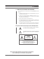
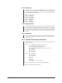
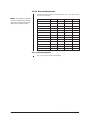
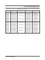
DRD08/DRD14 Series
Receiver/Drivers for
Intercept® Series
Domes
Installation/
Operation Manual
C466M-E (6/99)
Pelco • 3500 Pelco Way, Clovis • CA 93612-5699 USA • www.pelco.com
In North America and Canada: Tel (800) 289-9100 or FAX (800) 289-9150
International Customers: Tel (1-559) 292-1981 or FAX (1-559) 348-1120
CONTENTS
Section
Page
1.0 GENERAL .................................................................................................. 5
1.1 IMPORTANT SAFEGUARDS AND WARNINGS ............................... 5
2.0 DESCRIPTION .......................................................................................... 6
2.1 MODELS ............................................................................................ 6
3.0 INSTALLATION .......................................................................................... 8
3.1 ADJUSTMENTS ................................................................................ 8
3.1.1 CPU Board .............................................................................. 8
3.1.2 AC Power Supply Board PCB8500130 ................................... 8
3.1.3 DC Power Supply Board PCB8500140 .................................. 8
4.0 OPERATION ............................................................................................. 16
4.1 SCAN OPERATION .......................................................................... 16
4.2 PTZ (PAN/TILT AND LENS) CONTROLS ........................................ 16
4.3 PRESET FUNCTIONS ...................................................................... 17
4.4 FLIP FUNCTION ............................................................................... 17
4.5 ZONES ............................................................................................. 17
4.6 PATTERNS ....................................................................................... 18
4.7 CLEAR VIDEO SCREEN .................................................................. 18
4.8 RESET .............................................................................................. 18
5.0 FIRMWARE ............................................................................................... 19
5.1 COAXITRON CONTROL COMMAND .............................................. 19
5.1.1 PTZ (Pan/Tilt and Lens) Commands ..................................... 19
5.1.2 Extended Commands ............................................................ 20
5.2 AMERICAN DYNAMICS
AD2083 TYPE RS-422 CONTROL COMMAND ............................... 20
5.2.1 Protocol .................................................................................. 20
5.2.2 Addressing ............................................................................. 21
5.2.3 PTZ (Pan/Tilt and Lens) Commands ..................................... 21
5.2.4 Extended Commands ............................................................ 22
5.3 PELCO “P” TYPE RS-422 CONTROL .............................................. 22
5.3.1 Protocol .................................................................................. 22
5.3.2 Addressing ............................................................................. 23
5.3.3 Receiver Cards ...................................................................... 23
5.3.4 Commands ............................................................................ 23
5.3.4.1 PTZ (Pan/Tilt and Zoom) Commands ...................... 23
5.3.4.2 Extended Commands .............................................. 24
5.3.5 Acknowledgment ................................................................... 24
6.0 CIRCUIT BOARD PARTS LIST ................................................................ 25
7.0 SPECIFICATIONS .................................................................................... 26
7.1 REGULATORY NOTICES ................................................................. 27
8.0 WARRANTY AND RETURN INFORMATION ........................................... 28
2
Pelco Manual C466M-E (6/99)
LIST OF ILLUSTRATIONS
Figure
1
2
3
4
Page
PC Board Locations ........................................................................... 8
CPU Board ......................................................................................... 9
R26/R27 Adjustment Location ........................................................... 9
Receiver/Driver Reset Button Location ............................................. 18
LIST OF TABLES
Table
A
B
C
Page
Switch Settings for SW1 - D-Type Control ........................................ 10
Switch Settings for SW1 - P-Type Control ........................................ 15
Circuit Board Parts List ..................................................................... 25
REVISION HISTORY
Manual #
Pelco Manual C466M-E (6/99)
Date
Comments
C466M
9/93
Original Manual
C466M
9/94
Rev. A. Manual updated to include “P” version control
type, as well as the elimination of “B, C, E, and F”
control type information as per the following ECO
numbers: 94-27, 94-102, 94-118, 94-309, 94-348.
Manual converted to new layout design.
C466M-B
1/95
Rev. B. Manual revised to include additional address
and baud rate setting information, as well as updated
extended features and operation information as per the
following ECO numbers: 94-346, 94-347.
C466M-C
5/95
Rev. C. Manual updated to include additional Scan
Mode information as per ECO# 94-567.
C466M-D
7/95
Rev. D. Manual updated to include corrected information
on “D” and “P” version address switch settings (Figures
3 and 7).
C466M-E
1/98
Revised manual to reduce the number of models, to
modify installation instructions, and to incorporate
adden-dum of Feb. 13, 1996. Changed manual to new
format and manual pagination.
6/99
Revised manual to include applicable certifications.
Revised Section 5.3.4.1, Word Three, B1 and B0
functions.
3
(This page intentionally left blank.)
4
Pelco Manual C466M-E (6/99)
1.0 GENERAL
1.1 IMPORTANT SAFEGUARDS AND WARNINGS
Prior to installation and use of this product, the following WARNINGS should be
observed.
1.
Installation and servicing should only be done by Qualified Service Personnel
and conform to all Local codes.
2.
Unless the unit is specifically marked as a NEMA Type 3, 3R 3S, 4, 4X, 6, or
6P enclosure, it is designed for indoor use only and it must not be installed
where exposed to rain and moisture.
3.
Only use replacement parts recommended by Pelco.
4.
After replacement/repair of this unit’s electrical components, conduct a resistance measurement between line and exposed parts to verify the exposed
parts have not been connected to line circuitry.
5.
The installation method and materials should be capable of supporting four
(4) times the weight of the enclosure, pan/tilt, camera and lens combination.
The product and/or manual may bear the following marks:
This symbol indicates that dangerous voltage constituting a
risk of electric shock is present within this unit.
This symbol indicates that there are important operating and
maintenance instructions in the literature accompanying this
unit.
CAUTION:
RISK OF
ELECTRIC SHOCK.
DO NOT OPEN.
CAUTION:
TO REDUCE THE RISK OF ELECTRICAL SHOCK,
DO NOT REMOVE COVER. NO USERSERVICEABLE PARTS INSIDE. REFER SERVICING
TO QUALIFIED SERVICE PERSONNEL.
Please thoroughly familiarize yourself with the information
in this manual prior to installation and operation.
Pelco Manual C466M-E (6/99)
5
2.0 DESCRIPTION
The DRD08 Series of receiver/drivers is part of the IDS08 Intercept® Series of domes.
The IDS08 Series is an integral system that includes a back box (BB08), dome
drive (DD08), dome receiver/driver (DRD08), and imager/optics package (IOP08).
This manual covers the DRD08 Series of receiver/drivers. For installation and operation instructions for the back box, refer to manual C456M-D; for the dome drive,
refer to C416M-C; and for the imager/optics package, refer to C1441M-C.
The DRD14 Series of receiver/drivers is part of the IDS14 Series of domes. The
IDS14 Series is an integral system that includes a back box (BB14), dome drive
(DD14), and dome receiver/driver (DRD14). This manual covers the DRD14 Series
of receiver/drivers. For installation and operation instructions for the back box, refer
to manual C454M-C, and the the dome drive, refer to manual C458M-B.
2.1 MODELS
NOTE: The DRD (dome receiver/
driver) is not a field installable option; if it is to be used it must be
ordered on the original factory order of the Dome Drive.
6
DRD08A11
Receiver/driver for 8" Intercept® dome series. Basic receiver for
fixed-speed dome drive. Coaxitron® control.
DRD14A11
Same as DRD08A11 except for use with 14" Intercept® dome
series.
DRD14A12
Receiver/driver for 14" Intercept® dome series. Basic receiver
for variable-speed dome drive. Coaxitron® control.
DRD08A21
Receiver/driver for 8" Intercept® dome series. Enhanced receiver with preset positioning, zones, and patterns. For use with
fixed-speed dome drive. Coaxitron® control.
DRD14A21
Same as DRD08A21 except for use with 14" Intercept® dome
series.
DRD08A22
Receiver/driver for 8" Intercept® dome series. Enhanced receiver with preset positioning, zones, and patterns. For use with
variable-speed dome drive. Coaxitron® control.
DRD14A22
Same as DRD08A22 except for use with 14" Intercept® dome
series.
DRD08D11
Receiver/driver for 8" Intercept® dome series. Basic receiver for
fixed-speed dome drive. D-type control: RS-422 compatible
with Pelco’s MPT9500, CM6700 and CM8500 controllers or
with American Dynamics controllers using the AD2083 Translator.
DRD14D11
Same as DRD08D11 except for use with 14" Intercept® dome
series.
DRD14D12
Receiver/driver for 8" Intercept® dome series. Basic receiver for
variable-speed dome drive. D-type control: RS-422 compatible
with Pelco’s MPT9500, CM6700 and CM8500 controllers or
with American Dynamics controllers using the AD2083 Translator.
DRD08D21
Receiver/driver for 8" Intercept® dome series. Enhanced receiver with preset positioning, zones, and patterns. For use with
fixed-speed dome drive. D-type control: RS-422 compatible with
Pelco’s MPT9500, CM6700 and CM8500 controllers or with
American Dynamics controllers using the AD2083 Translator.
DRD14D21
Same as DRD08D21 except for use with 14" Intercept® dome
series.
Pelco Manual C466M-E (6/99)
Pelco Manual C466M-E (6/99)
DRD08D22
Receiver/driver for 8" Intercept® dome series. Enhanced receiver with preset positioning, zones, and patterns. For use with
variable-speed dome drive. D-type control: RS-422 compatible
with Pelco’s MPT9500, CM6700 and CM8500 controllers or
with American Dynamics controllers using the AD2083 Translator.
DRD14D22
Same as DRD08D22 except for use with 14" Intercept® dome
series.
DRD08P11
Receiver/driver for 8" Intercept® dome series. Basic receiver for
fixed-speed dome drive. P-type control: RS-422 compatible
with Pelco’s CM6700 and CM9750/CM9760 control systems.
DRD14P11
Same as DRD08P11 except for use with 14" Intercept® dome
series.
DRD14P12
Receiver/driver for 8" Intercept® dome series. Basic receiver for
variable-speed dome drive. P-type control: RS-422 compatible
with Pelco’s CM6700 and CM9750/CM9760 control systems.
DRD08P21
Receiver/driver for 8" Intercept® dome series. Enhanced receiver with preset positioning, zones, and patterns. For use with
fixed-speed dome drive. P-type control: RS-422 compatible
with Pelco’s CM6700 and CM9750/CM9760 control systems.
DRD14P21
Same as DRD08P21 except for use with 14" Intercept® dome
series.
DRD08P22
Receiver/driver for 8" Intercept® dome series. Enhanced receiver with preset positioning, zones, and patterns. For use with
variable-speed dome drive. P-type control: RS-422 compatible
with Pelco’s CM6700 and CM9750/CM9760 control systems.
DRD14P22
Same as DRD08P22 except for use with 14" Intercept® dome
series.
7
3.0 INSTALLATION
Installation of the Dome Receiver/Driver (DRD) into the DD08 or DD14 Dome Drive
is accomplished at the factory. This is not a field installable option.
3.1 ADJUSTMENTS
Although the DRD has been adjusted and set at the factory, some settings can and
may require field adjusting.
3.1.1 CPU Board
1.
JP3 is set at the factory in the RS-485 (422) position. Leave it in this position.
2.
JP5 and JP6 are both set in the UNTERM (unterminated) position. If the receiver
is using RS-422 and is the last physical receiver in the chain, then the setting
must be moved to the TERM (terminating) position (refer to Figures 1 and 2).
3.
JP1 and JP2 are used to decode the EPROM. They are factory set JP1 pin
2 to JP1 pin 3 and JP2 pin 1 to JP2 pin 2. DO NOT ALTER.
4.
SW1 receiver address switch is for those units whose firmware supports either
D- or P-type protocol. Refer to Figures 1 and 2 for the switch location. Refer to Table
A to set the receiver address for units that use D-type protocol. Refer to Table B
to set the receiver address and baud for units that use P-type protocol.
3.1.2 AC Power Supply Board PCB8500130
R26
20k ohm potentiometer sets the lens voltage. It is set at the
factory at 10 volts. Refer to Figures 1 and 3. Refer to Section 4.2
for more information.
3.1.3 DC Power Supply Board PCB8500140
R27
20k ohm potentiometer sets the lens voltage. It is set at the
factory at 10 volts. Refer to Figures 1 and 3. Refer to Section 4.2
for more information.
POWER SUPPLY BOARD
CPU BOARD
VIDEO BOARD
(COAXITRON® MODELS ONLY)
Figure 1. PC Board Locations
8
Pelco Manual C466M-E (6/99)
JP2
JP3
JP1
JP5 and JP6
RESET
SWITCH
JP5
TERMINATED
UNTERMINATED
JP6
SW1
ON
1 2 3 4 5 6 7 8
MADE IN USA
PCB8500110D
Figure 2. CPU Board
R26/R27
ADJUSTMENT
Figure 3. R26/R27 Adjustment Location
Pelco Manual C466M-E (6/99)
9
Table A. Switch Settings for SW1 - D-Type Control
NOTES: For Coaxitron® controls, SW1 is not used.
For P-type control systems, refer to Table B.
Receiver Address
1
2
3
4
5
6
7
8
9
10
11
12
13
14
15
16
17
18
19
20
21
22
23
24
25
26
26
28
29
30
31
32
33
34
35
36
37
38
39
40
41
42
43
44
45
46
47
48
SW1-1
SW1-2
SW1-3
Switch Setting
SW1-4
SW1-5
SW1-6
SW1-7
SW1-8
OFF
ON
OFF
ON
OFF
ON
OFF
ON
OFF
ON
OFF
ON
OFF
ON
OFF
ON
OFF
ON
OFF
ON
OFF
ON
OFF
ON
OFF
ON
OFF
ON
OFF
ON
OFF
ON
OFF
ON
OFF
ON
OFF
ON
OFF
ON
OFF
ON
OFF
ON
OFF
ON
OFF
ON
ON
OFF
OFF
ON
ON
OFF
OFF
ON
ON
OFF
OFF
ON
ON
OFF
OFF
ON
ON
OFF
OFF
ON
ON
OFF
OFF
ON
ON
OFF
OFF
ON
ON
OFF
OFF
ON
ON
OFF
OFF
ON
ON
OFF
OFF
ON
ON
OFF
OFF
ON
ON
OFF
OFF
ON
ON
ON
ON
OFF
OFF
OFF
OFF
ON
ON
ON
ON
OFF
OFF
OFF
OFF
ON
ON
ON
ON
OFF
OFF
OFF
OFF
ON
ON
ON
ON
OFF
OFF
OFF
OFF
ON
ON
ON
ON
OFF
OFF
OFF
OFF
ON
ON
ON
ON
OFF
OFF
OFF
OFF
ON
ON
ON
ON
ON
ON
ON
ON
OFF
OFF
OFF
OFF
OFF
OFF
OFF
OFF
ON
ON
ON
ON
ON
ON
ON
ON
OFF
OFF
OFF
OFF
OFF
OFF
OFF
OFF
ON
ON
ON
ON
ON
ON
ON
ON
OFF
OFF
OFF
OFF
OFF
OFF
OFF
OFF
ON
ON
ON
ON
ON
ON
ON
ON
ON
ON
ON
ON
ON
ON
ON
ON
ON
ON
ON
ON
ON
ON
ON
ON
ON
ON
ON
ON
ON
ON
ON
ON
OFF
OFF
OFF
OFF
OFF
OFF
OFF
OFF
OFF
OFF
OFF
OFF
OFF
OFF
OFF
OFF
OFF
ON
ON
ON
ON
ON
ON
ON
ON
ON
ON
ON
ON
ON
ON
ON
ON
ON
ON
ON
ON
ON
ON
ON
ON
ON
ON
ON
ON
ON
ON
ON
ON
ON
ON
ON
ON
ON
ON
ON
ON
ON
ON
ON
ON
ON
ON
ON
ON
ON
ON
ON
ON
ON
ON
ON
ON
ON
ON
ON
ON
ON
ON
ON
ON
ON
ON
ON
ON
ON
ON
ON
ON
ON
ON
ON
ON
ON
ON
ON
ON
ON
ON
ON
ON
ON
ON
ON
ON
ON
ON
ON
ON
ON
ON
ON
ON
ON
ON
ON
ON
ON
ON
ON
ON
ON
ON
ON
ON
ON
ON
ON
OFF
OFF
OFF
OFF
OFF
OFF
OFF
OFF
OFF
OFF
OFF
OFF
OFF
OFF
OFF
OFF
ON
ON
ON
ON
ON
ON
ON
ON
ON
ON
ON
ON
ON
ON
ON
ON
OFF
Continued on next page
10
Pelco Manual C466M-E (6/99)
Table A Switch Settings for SW1 - D-Type Control (continued)
Receiver Address
49
50
51
52
53
54
55
56
57
58
59
60
61
62
63
64
65
66
67
68
69
70
71
72
73
74
75
76
77
78
79
80
81
82
83
84
85
86
87
88
89
90
91
92
93
94
95
96
97
98
99
100
SW1-1
SW1-2
SW1-3
Switch Setting
SW1-4
SW1-5
SW1-6
SW1-7
SW1-8
OFF
ON
OFF
ON
OFF
ON
OFF
ON
OFF
ON
OFF
ON
OFF
ON
OFF
ON
OFF
ON
OFF
ON
OFF
ON
OFF
ON
OFF
ON
OFF
ON
OFF
ON
OFF
ON
OFF
ON
OFF
ON
OFF
ON
OFF
ON
OFF
ON
OFF
ON
OFF
ON
OFF
ON
OFF
ON
OFF
ON
ON
OFF
OFF
ON
ON
OFF
OFF
ON
ON
OFF
OFF
ON
ON
OFF
OFF
ON
ON
OFF
OFF
ON
ON
OFF
OFF
ON
ON
OFF
OFF
ON
ON
OFF
OFF
ON
ON
OFF
OFF
ON
ON
OFF
OFF
ON
ON
OFF
OFF
ON
ON
OFF
OFF
ON
ON
OFF
OFF
ON
ON
ON
ON
OFF
OFF
OFF
OFF
ON
ON
ON
ON
OFF
OFF
OFF
OFF
ON
ON
ON
ON
OFF
OFF
OFF
OFF
ON
ON
ON
ON
OFF
OFF
OFF
OFF
ON
ON
ON
ON
OFF
OFF
OFF
OFF
ON
ON
ON
ON
OFF
OFF
OFF
OFF
ON
ON
ON
ON
OFF
ON
ON
ON
ON
ON
ON
ON
OFF
OFF
OFF
OFF
OFF
OFF
OFF
OFF
ON
ON
ON
ON
ON
ON
ON
ON
OFF
OFF
OFF
OFF
OFF
OFF
OFF
OFF
ON
ON
ON
ON
ON
ON
ON
ON
OFF
OFF
OFF
OFF
OFF
OFF
OFF
OFF
ON
ON
ON
ON
ON
OFF
OFF
OFF
OFF
OFF
OFF
OFF
OFF
OFF
OFF
OFF
OFF
OFF
OFF
OFF
ON
ON
ON
ON
ON
ON
ON
ON
ON
ON
ON
ON
ON
ON
ON
ON
ON
ON
ON
ON
ON
ON
ON
ON
ON
ON
ON
ON
ON
ON
ON
ON
OFF
OFF
OFF
OFF
OFF
ON
ON
ON
ON
ON
ON
ON
ON
ON
ON
ON
ON
ON
ON
ON
OFF
OFF
OFF
OFF
OFF
OFF
OFF
OFF
OFF
OFF
OFF
OFF
OFF
OFF
OFF
OFF
OFF
OFF
OFF
OFF
OFF
OFF
OFF
OFF
OFF
OFF
OFF
OFF
OFF
OFF
OFF
OFF
OFF
OFF
OFF
OFF
OFF
ON
ON
ON
ON
ON
ON
ON
ON
ON
ON
ON
ON
ON
ON
ON
ON
ON
ON
ON
ON
ON
ON
ON
ON
ON
ON
ON
ON
ON
ON
ON
ON
ON
ON
ON
ON
ON
ON
ON
ON
ON
ON
ON
ON
ON
ON
ON
ON
ON
ON
ON
ON
OFF
OFF
OFF
OFF
OFF
OFF
OFF
OFF
OFF
OFF
OFF
OFF
OFF
OFF
OFF
ON
ON
ON
ON
ON
ON
ON
ON
ON
ON
ON
ON
ON
ON
ON
ON
OFF
OFF
OFF
OFF
OFF
OFF
OFF
OFF
OFF
OFF
OFF
OFF
OFF
OFF
OFF
OFF
ON
ON
ON
ON
ON
Continued on next page
Pelco Manual C466M-E (6/99)
11
Table A Switch Settings for SW1 - D-Type Control (continued)
Receiver Address
101
102
103
104
105
106
107
108
109
110
111
112
113
114
115
116
117
118
119
120
121
122
123
124
125
126
127
128
129
130
131
132
133
134
135
136
137
138
139
140
141
142
143
144
145
146
147
148
149
150
151
152
SW1-1
SW1-2
SW1-3
Switch Setting
SW1-4
SW1-5
SW1-6
SW1-7
SW1-8
OFF
ON
OFF
ON
OFF
ON
OFF
ON
OFF
ON
OFF
ON
OFF
ON
OFF
ON
OFF
ON
OFF
ON
OFF
ON
OFF
ON
OFF
ON
OFF
ON
OFF
ON
OFF
ON
OFF
ON
OFF
ON
OFF
ON
OFF
ON
OFF
ON
OFF
ON
OFF
ON
OFF
ON
OFF
ON
OFF
ON
ON
OFF
OFF
ON
ON
OFF
OFF
ON
ON
OFF
OFF
ON
ON
OFF
OFF
ON
ON
OFF
OFF
ON
ON
OFF
OFF
ON
ON
OFF
OFF
ON
ON
OFF
OFF
ON
ON
OFF
OFF
ON
ON
OFF
OFF
ON
ON
OFF
OFF
ON
ON
OFF
OFF
ON
ON
OFF
OFF
ON
OFF
OFF
OFF
ON
ON
ON
ON
OFF
OFF
OFF
OFF
ON
ON
ON
ON
OFF
OFF
OFF
OFF
ON
ON
ON
ON
OFF
OFF
OFF
OFF
ON
ON
ON
ON
OFF
OFF
OFF
OFF
ON
ON
ON
ON
OFF
OFF
OFF
OFF
ON
ON
ON
ON
OFF
OFF
OFF
OFF
ON
ON
ON
ON
OFF
OFF
OFF
OFF
OFF
OFF
OFF
OFF
ON
ON
ON
ON
ON
ON
ON
ON
OFF
OFF
OFF
OFF
OFF
OFF
OFF
OFF
ON
ON
ON
ON
ON
ON
ON
ON
OFF
OFF
OFF
OFF
OFF
OFF
OFF
OFF
ON
ON
ON
ON
ON
ON
ON
ON
OFF
OFF
OFF
OFF
OFF
OFF
OFF
OFF
OFF
OFF
OFF
OFF
OFF
OFF
OFF
OFF
OFF
OFF
OFF
OFF
OFF
OFF
OFF
OFF
OFF
OFF
OFF
OFF
ON
ON
ON
ON
ON
ON
ON
ON
ON
ON
ON
ON
ON
ON
ON
ON
ON
ON
ON
ON
ON
ON
ON
ON
ON
OFF
OFF
OFF
OFF
OFF
OFF
OFF
OFF
OFF
OFF
OFF
OFF
OFF
OFF
OFF
OFF
OFF
OFF
OFF
OFF
OFF
OFF
OFF
OFF
OFF
OFF
OFF
ON
ON
ON
ON
ON
ON
ON
ON
ON
ON
ON
ON
ON
ON
ON
ON
ON
ON
ON
ON
ON
ON
ON
ON
ON
ON
ON
ON
ON
ON
ON
ON
ON
ON
ON
ON
ON
ON
ON
ON
ON
ON
ON
ON
ON
ON
ON
ON
ON
ON
ON
ON
OFF
OFF
OFF
OFF
OFF
OFF
OFF
OFF
OFF
OFF
OFF
OFF
OFF
OFF
OFF
OFF
OFF
OFF
OFF
OFF
OFF
OFF
OFF
OFF
OFF
ON
ON
ON
ON
ON
ON
ON
ON
ON
ON
ON
OFF
OFF
OFF
OFF
OFF
OFF
OFF
OFF
OFF
OFF
OFF
OFF
OFF
OFF
OFF
OFF
ON
ON
ON
ON
ON
ON
ON
ON
ON
ON
ON
ON
ON
ON
ON
ON
OFF
OFF
OFF
OFF
OFF
OFF
OFF
OFF
OFF
Continued on next page
12
Pelco Manual C466M-E (6/99)
Table A Switch Settings for SW1 - D-Type Control (continued)
Receiver Address
153
154
155
156
157
158
159
160
161
162
163
164
165
166
167
168
169
170
171
172
173
174
175
176
177
178
179
180
181
182
183
184
185
186
187
188
189
190
191
192
193
194
195
196
197
198
199
200
201
202
203
204
SW1-1
SW1-2
SW1-3
Switch Setting
SW1-4
SW1-5
SW1-6
SW1-7
SW1-8
OFF
ON
OFF
ON
OFF
ON
OFF
ON
OFF
ON
OFF
ON
OFF
ON
OFF
ON
OFF
ON
OFF
ON
OFF
ON
OFF
ON
OFF
ON
OFF
ON
OFF
ON
OFF
ON
OFF
ON
OFF
ON
OFF
ON
OFF
ON
OFF
ON
OFF
ON
OFF
ON
OFF
ON
OFF
ON
OFF
ON
ON
OFF
OFF
ON
ON
OFF
OFF
ON
ON
OFF
OFF
ON
ON
OFF
OFF
ON
ON
OFF
OFF
ON
ON
OFF
OFF
ON
ON
OFF
OFF
ON
ON
OFF
OFF
ON
ON
OFF
OFF
ON
ON
OFF
OFF
ON
ON
OFF
OFF
ON
ON
OFF
OFF
ON
ON
OFF
OFF
ON
ON
ON
ON
OFF
OFF
OFF
OFF
ON
ON
ON
ON
OFF
OFF
OFF
OFF
ON
ON
ON
ON
OFF
OFF
OFF
OFF
ON
ON
ON
ON
OFF
OFF
OFF
OFF
ON
ON
ON
ON
OFF
OFF
OFF
OFF
ON
ON
ON
ON
OFF
OFF
OFF
OFF
ON
ON
ON
ON
OFF
OFF
OFF
OFF
OFF
OFF
OFF
OFF
ON
ON
ON
ON
ON
ON
ON
ON
OFF
OFF
OFF
OFF
OFF
OFF
OFF
OFF
ON
ON
ON
ON
ON
ON
ON
ON
OFF
OFF
OFF
OFF
OFF
OFF
OFF
OFF
ON
ON
ON
ON
ON
ON
ON
ON
OFF
OFF
OFF
OFF
OFF
ON
ON
ON
ON
ON
ON
ON
OFF
OFF
OFF
OFF
OFF
OFF
OFF
OFF
OFF
OFF
OFF
OFF
OFF
OFF
OFF
OFF
OFF
OFF
OFF
OFF
OFF
OFF
OFF
OFF
OFF
OFF
OFF
OFF
OFF
OFF
OFF
OFF
ON
ON
ON
ON
ON
ON
ON
ON
ON
ON
ON
ON
ON
ON
ON
ON
ON
ON
ON
ON
ON
ON
ON
ON
ON
ON
ON
ON
ON
ON
ON
ON
ON
ON
ON
ON
ON
ON
ON
ON
ON
ON
ON
ON
ON
ON
ON
ON
ON
ON
ON
ON
OFF
OFF
OFF
OFF
OFF
OFF
OFF
OFF
OFF
OFF
OFF
OFF
OFF
OFF
OFF
OFF
OFF
OFF
OFF
OFF
OFF
OFF
OFF
OFF
OFF
OFF
OFF
OFF
OFF
OFF
OFF
OFF
OFF
OFF
OFF
OFF
OFF
OFF
OFF
OFF
OFF
OFF
OFF
OFF
OFF
OFF
OFF
OFF
OFF
OFF
OFF
OFF
OFF
OFF
OFF
OFF
OFF
OFF
OFF
OFF
OFF
OFF
OFF
OFF
OFF
OFF
OFF
OFF
OFF
OFF
OFF
OFF
ON
ON
ON
ON
ON
ON
ON
ON
ON
ON
ON
ON
ON
ON
ON
ON
OFF
OFF
OFF
OFF
OFF
OFF
OFF
OFF
OFF
OFF
OFF
OFF
OFF
OFF
OFF
OFF
ON
ON
ON
ON
ON
ON
ON
ON
ON
ON
ON
ON
ON
Continued on next page
Pelco Manual C466M-E (6/99)
13
Table A Switch Settings for SW1 - D-Type Control (continued)
Receiver Address
205
206
207
208
209
210
211
212
213
214
215
216
217
218
219
220
221
222
223
224
225
226
227
228
229
230
231
232
233
234
235
236
237
238
239
240
241
242
243
244
245
246
247
248
249
250
251
252
253
254
14
SW1-1
SW1-2
SW1-3
Switch Setting
SW1-4
SW1-5
SW1-6
SW1-7
SW1-8
OFF
ON
OFF
ON
OFF
ON
OFF
ON
OFF
ON
OFF
ON
OFF
ON
OFF
ON
OFF
ON
OFF
ON
OFF
ON
OFF
ON
OFF
ON
OFF
ON
OFF
ON
OFF
ON
OFF
ON
OFF
ON
OFF
ON
OFF
ON
OFF
ON
OFF
ON
OFF
ON
OFF
ON
OFF
ON
ON
OFF
OFF
ON
ON
OFF
OFF
ON
ON
OFF
OFF
ON
ON
OFF
OFF
ON
ON
OFF
OFF
ON
ON
OFF
OFF
ON
ON
OFF
OFF
ON
ON
OFF
OFF
ON
ON
OFF
OFF
ON
ON
OFF
OFF
ON
ON
OFF
OFF
ON
ON
OFF
OFF
ON
ON
OFF
OFF
OFF
OFF
ON
ON
ON
ON
OFF
OFF
OFF
OFF
ON
ON
ON
ON
OFF
OFF
OFF
OFF
ON
ON
ON
ON
OFF
OFF
OFF
OFF
ON
ON
ON
ON
OFF
OFF
OFF
OFF
ON
ON
ON
ON
OFF
OFF
OFF
OFF
ON
ON
ON
ON
OFF
OFF
OFF
OFF
OFF
OFF
ON
ON
ON
ON
ON
ON
ON
ON
OFF
OFF
OFF
OFF
OFF
OFF
OFF
OFF
ON
ON
ON
ON
ON
ON
ON
ON
OFF
OFF
OFF
OFF
OFF
OFF
OFF
OFF
ON
ON
ON
ON
ON
ON
ON
ON
OFF
OFF
OFF
OFF
OFF
OFF
OFF
ON
ON
ON
ON
ON
ON
ON
ON
ON
ON
ON
ON
ON
ON
ON
ON
ON
ON
ON
OFF
OFF
OFF
OFF
OFF
OFF
OFF
OFF
OFF
OFF
OFF
OFF
OFF
OFF
OFF
OFF
OFF
OFF
OFF
OFF
OFF
OFF
OFF
OFF
OFF
OFF
OFF
OFF
OFF
OFF
OFF
OFF
OFF
OFF
OFF
OFF
OFF
OFF
OFF
OFF
OFF
OFF
OFF
OFF
OFF
OFF
OFF
OFF
OFF
OFF
OFF
OFF
OFF
OFF
OFF
OFF
OFF
OFF
OFF
OFF
OFF
OFF
OFF
OFF
OFF
OFF
OFF
OFF
OFF
OFF
OFF
OFF
OFF
OFF
OFF
OFF
OFF
OFF
OFF
OFF
OFF
OFF
OFF
OFF
OFF
OFF
OFF
OFF
OFF
OFF
OFF
OFF
OFF
OFF
OFF
OFF
OFF
OFF
OFF
OFF
OFF
OFF
OFF
OFF
OFF
OFF
OFF
OFF
OFF
OFF
OFF
OFF
OFF
OFF
OFF
OFF
OFF
OFF
OFF
OFF
OFF
OFF
OFF
OFF
OFF
OFF
OFF
OFF
OFF
OFF
OFF
ON
ON
ON
OFF
OFF
OFF
OFF
OFF
OFF
OFF
OFF
OFF
OFF
OFF
OFF
OFF
OFF
OFF
OFF
ON
ON
ON
ON
ON
ON
ON
ON
ON
ON
ON
ON
ON
ON
ON
ON
OFF
OFF
OFF
OFF
OFF
OFF
OFF
OFF
OFF
OFF
OFF
OFF
OFF
OFF
OFF
Pelco Manual C466M-E (6/99)
Table B. Switch Settings for SW1 - P-Type Control
NOTES: For Coaxitron® controls, SW1 is not used.
For D-type control systems, refer to Table A.
Receiver Address
1
2
3
4
5
6
7
8
9
10
11
12
13
14
15
16
17
18
19
20
21
22
23
24
25
26
27
28
29
30
31
32
SW1-1
SW1-2
ON
OFF
ON
OFF
ON
OFF
ON
OFF
ON
OFF
ON
OFF
ON
OFF
ON
OFF
ON
OFF
ON
OFF
ON
OFF
ON
OFF
ON
OFF
ON
OFF
ON
OFF
ON
OFF
ON
ON
OFF
OFF
ON
ON
OFF
OFF
ON
ON
OFF
OFF
ON
ON
OFF
OFF
ON
ON
OFF
OFF
ON
ON
OFF
OFF
ON
ON
OFF
OFF
ON
ON
OFF
OFF
Baud
SW1-6
9600
4800
2400
Pelco Manual C466M-E (6/99)
OFF
ON
ON
Switch Setting
SW1-3
ON
ON
ON
ON
OFF
OFF
OFF
OFF
ON
ON
ON
ON
OFF
OFF
OFF
OFF
ON
ON
ON
ON
OFF
OFF
OFF
OFF
ON
ON
ON
ON
OFF
OFF
OFF
OFF
Switch Setting
SW1-7
ON
OFF
ON
SW1-4
SW1-5
ON
ON
ON
ON
ON
ON
ON
ON
OFF
OFF
OFF
OFF
OFF
OFF
OFF
OFF
ON
ON
ON
ON
ON
ON
ON
ON
OFF
OFF
OFF
OFF
OFF
OFF
OFF
OFF
ON
ON
ON
ON
ON
ON
ON
ON
ON
ON
ON
ON
ON
ON
ON
ON
OFF
OFF
OFF
OFF
OFF
OFF
OFF
OFF
OFF
OFF
OFF
OFF
OFF
OFF
OFF
OFF
SW1-8
ON
ON
OFF
15
4.0 OPERATION
Upon applying power, the unit starts a configuration routine after 15 seconds.
4.1 SCAN OPERATION
Three (3) different scan mode options are offered and can be selected according to
operator preference:
Auto Scan; (AUX 2), continuous panning, with a 5-second stop on limits.
Random Scan; (AUX 3) random operation.
Frame Scan; (AUX 4) with 5 seconds of travel followed by 5 seconds of stop.
To select a scan mode (at the system controller), select the appropriate AUX button, then select scan.
4.2 PTZ (PAN/TILT AND LENS) CONTROLS
16
1.
The DRD08**2 pan mechanism under standard operator control will move at less
than one (1) degree per second and as fast as 40 degrees per second. In the
preset or turbo mode, the unit will pan at greater than 200 degrees per second.
2.
The DRD14**2 pan mechanism under standard operator control will move at less
than one (1) degree per second and as fast as 20 degrees per second. In the
preset or turbo mode, the unit will pan at greater than 100 degrees per second.
3.
The DRD08**2 tilt mechanism under standard operator control will move at
less than one (1) degree per second and as fast as 40 degrees per second. In
preset mode, the unit will tilt at 90 degrees per second.
4.
The DRD14**2 tilt mechanism under standard operator control will move at
less than one (1) degree per second and as fast as 40 degrees per second. In
preset mode, the unit will tilt at 45 degrees per second.
5.
The DRD***2* lens functions are dependent on the lens used. The lens voltage can be set as described in section 3.1.2 or 3.1.3, depending on which is
applicable. This voltage will set the highest speed at which the lens can move.
For slower speeds the DRD can be programmed by the controller for 3/4 and
1/2 of this speed as described in the firmware section of this manual.
Pelco Manual C466M-E (6/99)
4.3 PRESET FUNCTIONS
NOTE: Preset commands are
only in the 32-bit format.
NOTE: If the DRD is commanded
1.
The DRD***2* units are capable of 32 complete preset scenes. On DRD**A2*
models, each preset can have a 20-character label. To set a preset, first enter
the label then program the position.
2.
Once programmed, the DRD***2* can be commanded to the preset. Resolution of the pan and tilt position is 1/2 degree.
3.
There are two (2) additional presets that can be programmed; they are preset 33 “FLIP” command which will pan the dome drive 180 degrees from the
position it is at, and preset 34 “PAN ZERO” which will direct the dome drive
to the factory determined zero reference point.
to an undefined preset, erratic operation will result.
The following applies to dome firmware revision PRG08A21U3-R2.2 and higher
for DRD08A21 and DRD14A21 dome receiver/driver types.
With pan limit stops installed, and when calling preset 34, the dome will move to the
PAN ZERO position. After arriving at this position, the dome may bounce or jitter
back and forth in half-degree increments around the zero position. If left undisturbed, the unit will continue this action until the 60-second time out has been
reached. Control of the dome can be resumed at any time by sending a command.
Preset 34 is used in this application to set a zone across the zero position. To accomplish this in light of the above mentioned problem, follow the procedure outlined below.
1.
Send the dome to preset 34.
2.
When the dome arrives at the PAN ZERO position and begins to jitter, abort the
preset call by actuating a lens function. The dome should now be positioned at
the correct position, and the procedure in Section 4.5, ZONES, can be followed.
4.4 FLIP FUNCTION
The flip feature will move the pan position 180 degrees.
4.5 ZONES
NOTE: Zone scan must be OFF
1.
The DRD**A2* units are capable of 8 zones, each with a 20-character label.
To set a zone, first move the unit to the left-most zone point, enter the label,
then set the zone start point.
2.
Next move the unit to the right to the second position and program the zone
end point. The zone priority is from zone 8 to zone 1 with zone 8 having the
highest priority. This means if two zones overlap, the one with the highest
priority will be displayed.
to program zones.
Programming the
DRD**A21 across the factory determined zero point will require
splitting the zone in two, using the
zero point as the end of one of the
zones and the beginning of the
other zone.
NOTE:
Pelco Manual C466M-E (6/99)
17
4.6 PATTERNS
1.
The DRD***2* units are capable of one 60-second pattern. This pattern can
consist of any standard pan/tilt or lens command. Presets, flip and turbo are
not allowed in a pattern. Zone scan can be enabled while running a pattern.
2.
To program a pattern first move the pan/tilt and adjust the lens to the starting
point desired. Engage the Pattern Programming command. The message
“PROGRAMMING PATTERN” will be displayed. After this, any movement for
the next 60 seconds will be remembered by the DRD. To create a pattern that
plays back only once, continue programming until the message is removed.
To create a pattern that repeats you must terminate the program before the
time-out occurs and the DRD removes the message.
3.
To play back a pattern, engage the Run Pattern command. The unit will move
to the defined starting position and display the message “RUNNING PATTERN”.
Any subsequent command will terminate the pattern.
4.7 CLEAR VIDEO SCREEN
To clear the video display of any text supplied by the DRD, engage the Clear Video
Text command.
4.8 RESET
On all units except the DRD***11 models, there is a reset switch on the CPU board
(refer to Figure 4). If the dome drive stops working, try resetting it by pushing the
reset switch for 10 seconds. In about 15 seconds, if the unit is working, it will begin
to move and go through its start-up routine. You may also be able to issue a reset
command from your controller; check the documentation for your controller.
RESET BUTTON
Figure 4. Receiver/Driver Reset Button Location
18
Pelco Manual C466M-E (6/99)
5.0 FIRMWARE
5.1 COAXITRON CONTROL COMMAND
This section describes the protocol used to send commands to the receivers via
Coaxitron.
The hardware interface is a 32-bit PWM (pulse width modulated) signal, wherein a
one microsecond pulse is considered a zero and a two microsecond pulse is considered a one. There will be a minimum one (1) microsecond off space between
pulses. Line 18 will contain Bytes 1 and 2, line 19 will contain Bytes 3 and 4.
Commands are divided into two (2) categories. The first is referred to as PTZ (pan
and tilt and lens) commands; the second category is Extended commands.
5.1.1 PTZ (Pan/Tilt and Lens) Commands
All PTZ (pan/tilt and lens) commands will always have B0 of Byte 2 set to zero. The
remainder of the format is as follows:
Byte 1:
B7 — Camera on, auto scan
B6 — Coaxitron usage only
B5 — Coaxitron usage only
B4 — Auto scan, manual scan
B3 — Camera on, camera off
B2 — Iris close
B1 — Iris open
B0 — Focus near
Byte 2:
B7 — Focus far
B6 — Zoom wide
B5 — Zoom tele
B4 — Down
B3 — Up
B2 — Left
B1 — Right
B0 — always zero for a PTZ command
Byte 3:
Pan speed with values 0 to 0x3F and 0xFF (pan turbo)
Byte 4:
Tilt speed with values 0 to 0x3F
Examples:
Pelco Manual C466M-E (6/99)
Left, half Speed
Left, Turbo Speed
Stop
00 04 1F 00
00 04 FF 00
00 00 00 00
19
5.1.2 Extended Commands
Extended commands will always have B0 of Byte 2 set to one. The following numbers are in hexadecimal format:
Command
Byte 1
Byte 2
Byte 3
Byte 4
Set preset XX
00
03
00
01 to 20
Clear preset XX
00
05
00
01 to 20
Go to preset XX
00
07
00
01 to 20
80 FLIP preset
00
07
00
21
Set aux XX
00
09
00
01 to 08
Clear aux XX
00
0B
00
01 to 08
Remote Reset
00
0F
00
00
Program zone XX
starting point
00
11
00
01 to 08
Program zone XX
ending point
00
13
00
01 to 08
Write character YY
to screen position XX
00
15
0 to 27
YY
Clear screen
00
17
00
00
Zone Scan On
00
1B
00
00
Zone Scan Off
00
1D
00
00
Pattern Start Point
00
1F
00
00
Pattern Stop Point
00
21
00
00
Run Pattern
00
23
00
00
Lens Speed
00
25
00
00 to 03
5.2 AMERICAN DYNAMICS
AD2083 TYPE RS-422 CONTROL COMMAND
5.2.1 Protocol
1.
2.
The following describes the protocol used to send commands to the receivers
via RS-422.
a.
The hardware interface is four-wire RS-422, where one pair is used to
issue commands to the receiver and one pair is used to receive responses
from the receiver.
b.
The protocol: one start bit, eight bits data, and one stop bit at 2400 baud.
The message format is 7 of these 10-bit words. Word one is the sync and is set
to 0xFF, word two is the receiver address, words three and four are referred to
as commands, words five and six as data, and word seven is the check sum.
Commands are divided into two categories. The first is referred to as PTZ (pan and
tilt and lens) commands, the second category is Extended commands.
20
Pelco Manual C466M-E (6/99)
5.2.2 Addressing
The address is set on the CPU board PCB8500110. The switch is labeled SW1.
Setting the switch in the “ON” position represents a zero. Refer to Table A.
NOTE: Do not use addresses 0 or
255.
SW1.1
SW1.2
SW1.3
SW1.4
SW1.5
SW1.6
SW1.7
SW1.8
Address Bit 0
Address Bit 1
Address Bit 2
Address Bit 3
Address Bit 4
Address Bit 5
Address Bit 6
Address Bit 7
5.2.3 PTZ (Pan/Tilt and Lens) Commands
All PTZ (pan/tilt and lens) commands will always have B0 of word 4 set to zero. The
remainder of the format is as follows:
Word 3:
B7 — Camera on, auto scan
B6 — Coaxitron usage only
B5 — Coaxitron usage only
B4 — Auto scan, manual scan
B3 — Camera on, camera off
B2 — Iris close
B1 — Iris open
B0 — Focus near
Word 4:
B7 — Focus far
B6 — Zoom wide
B5 — Zoom tele
B4 — Down
B3 — Up
B2 — Left
B1 — Right
B0 — Always zero for a PTZ command
Word 5:
Pan speed with values 0 to 0x3F and 0x40 (pan turbo)
Word 6:
Tilt speed with values 0 to 0x3F
The following examples are for Words 3, 4, 5 and 6:
Left, Half Speed
Left, Turbo Speed
Stop
Pelco Manual C466M-E (6/99)
00 04 1F 00
00 04 40 00
00 00 00 00
21
5.2.4 Extended Commands
Extended commands will always have B0 of Word 4 set to one. The following numbers are in hexadecimal format:
Word 3
Word 4
Word 5
Word 6
Set preset XX
Command
00
03
00
01 to 20
Clear preset XX
00
05
00
01 to 20
Go to preset XX
00
07
00
01 to 20
180 FLIP preset
00
07
00
21
Zero pan position
00
07
00
22
Set aux XX
00
09
00
01 to 08
Clear aux XX
00
0B
00
01 to 08
Remote Reset
00
0F
00
00
Clear screen
00
17
00
00
Pattern Start Point
00
1F
00
00
Pattern Stop Point
00
21
00
00
Run Pattern
00
23
00
00
Lens Speed
00
25
00
00 to 03
The four word response format is: word one is the sync 0xFF, word 2 is the receiver
address, word 3 is the alarm information, and word 4 is a return check sum (which
is the transmitted check sum added to the alarm information).
5.3 PELCO “P” TYPE RS-422 CONTROL
5.3.1 Protocol
This section describes the protocol used to send commands to the receivers via
RS-422. The hardware interface is four-wire RS-422, where one pair is used to
issue commands to the receiver. The protocol is one start bit, eight bits data, and
one stop bit at 9600, 4800 or 2400 baud. The message format is 8 of these 10-bit
words with the following format:
WORD 1 — STX (0XA0)
WORD 2 — ADD (0 to 0X1F)
WORD 3 — Data as described below
WORD 4 — Data as described below
WORD 5 — Data as described below
WORD 6 — Data as described below
WORD 7 — ETX (0XAF)
WORD 8 — CRC
22
Pelco Manual C466M-E (6/99)
5.3.2 Addressing
The address is set on the CPU board PCB8500110. The switch is labeled SW1.
Setting the switch in the “ON” position represents a zero. The first five positions set
the receiver address (1 through 5) from a range of 0 to 31. The last three (6 through 8)
set the baud rate. Refer to Table B.
SW1.1 — Address Bit 0
SW1.2 — Address Bit 1
SW1.3 — Address Bit 2
SW1.4 — Address Bit 3
SW1.5 — Address Bit 4
SW1.6 — 9600 Baud
SW1.7 — 4800 Baud
SW1.8 — 2400 Baud
5.3.3 Receiver Cards
The RS-422 style Intercept® receivers use only two of the three receiver cards.
There must be a power supply (either AC or DC) and a CPU card. The video card is
not used. Therefore the camera video output is connected directly to the slip ring.
This eliminates the dome’s ability to superimpose text on the video. This eliminates
any label and zone feature. If these features are needed additional firmware will be
needed.
5.3.4 Commands
Commands are divided into two (2) categories. The first is referred to as PTZ commands. The second category is Extended commands. The paragraphs below describe their functions.
5.3.4.1 PTZ (Pan/Tilt and Zoom) Commands
PTZ commands will always have B0 of word 4 set to zero. The remainder of the
format is as follows.
Pelco Manual C466M-E (6/99)
Word 3
B7 — Always Zero (was camera on, auto scan)
B6 — Camera On (was Coaxitron usage only)
B5 — Auto Scan On (was Coaxitron only)
B4 — Camera On, Camera Off (was auto scan, manual scan)
B3 — Iris Close
B2 — Iris Open
B1 — Focus Near
B0 — Focus Far
Word 4
B7 — Always Zero
B6 — Zoom Wide
B5 — Zoom Tele
B4 — Down
B3 — Up
B2 — Left
B1 — Right
B0 — Always Zero for PTZ command
Word 5
Pan speed with values 0 to 0x3F and 0xx40 (Pan Turbo)
Word 6
Tilt speed with values 0 to 0x3F
23
5.3.4.2 Extended Commands
Extended commands will always have B0 of Word 4 set to 1. The numbers below
are in hexadecimal format.
NOTE: The extended commands
above are available at the receiver;
make sure commands can be initiated by the controlling system.
Command
Word 3
Word 4
Word 5
Word 6
Set preset XX
00
03
00
01 to 20
Clear preset XX
00
05
00
01 to 20
Go to preset XX
00
07
00
01 to 20
180 Flip preset
00
07
00
21
Zero pan position
00
07
00
22
Set aux XX
00
09
00
01 to 08
Clear aux XX
00
0B
00
01 to 08
Remote Reset
00
0F
00
00
Pat. Start Point
00
1F
00
00
Pat. Stop Point
00
21
00
00
Run Pattern
00
23
00
00
Zoom Lens speed
00
25
00
00 to 03
Focus Lens speed
00
27
00
00 to 03
5.3.5 Acknowledgment
The receiver will respond with an ACK (0XA2).
24
Pelco Manual C466M-E (6/99)
6.0 CIRCUIT BOARD PARTS LIST
Table C. Circuit Board Parts List
Model
CPU Board
Video Board
Power Board
Backplane
DRD08A11
DRD08D11
DRD08P11
DRD08A21
DRD08D21
DRD08P21
DRD08A22
DRD08D22
DRD08P22
CPU08A11ASSY
CPU08D11ASSY
CPU08P11ASSY
CPU08A21ASSY
CPU08D21ASSY
CPU08P21ASSY
CPU08A22ASSY
CPU08D22ASSY
CPU08P22ASSY
PCB8500101ASSY
PCB8500130ASSY
PCB8500130ASSY
PCB8500130ASSY
PCB8500130ASSY
PCB8500130ASSY
PCB8500130ASSY
PCB8500140ASSY
PCB8500140ASSY
PCB8500140ASSY
PCB8500150ASSY
PCB8500151ASSY
PCB8500151ASSY
PCB8500150ASSY
PCB8500151ASSY
PCB8500151ASSY
PCB8500150ASSY
PCB8500151ASSY
PCB8500151ASSY
DRD14A11
DRD14D11
DRD14P11
DRD14A12
DRD14D12
DRD14P12
DRD14A21
DRD14D21
DRD14P21
DRD14A22
DRD14D22
DRD14P22
CPU14A11ASSY
CPU14D11ASSY
CPU14P11ASSY
CPU14A12ASSY
CPU14D12ASSY
CPU14P12ASSY
CPU14A21ASSY
CPU14D21ASSY
CPU14P21ASSY
CPU14A22ASSY
CPU14D22ASSY
CPU14P22ASSY
PCB8500101ASSY
PCB8500130ASSY
PCB8500130ASSY
PCB8500130ASSY
PCB8500140ASSY
PCB8500140ASSY
PCB8500140ASSY
PCB8500130ASSY
PCB8500130ASSY
PCB8500130ASSY
PCB8500140ASSY
PCB8500140ASSY
PCB8500140ASSY
PCB8500150ASSY
PCB8500151ASSY
PCB8500151ASSY
PCB8500150ASSY
PCB8500151ASSY
PCB8500151ASSY
PCB8500150ASSY
PCB8500151ASSY
PCB8500151ASSY
PCB8500150ASSY
PCB8500151ASSY
PCB8500151ASSY
Pelco Manual C466M-E (6/99)
PCB8500100ASSY
PCB8500100ASSY
PCB8500101ASSY
PCB8500100ASSY
PCB8500100ASSY
25
7.0 SPECIFICATIONS
Input Voltage:
Maximum
Input Power
AC Motor
Dome Drive:
DC Stepper
Motor Dome
Drive:
24 VAC, 60 Hz, ±10% at the drive
Pan — 7.5 vA
Tilt — 7.5 vA
Idle — 2.5 vA
Pan
— 32 vA
Tilt
— 32 vA
Pan/Tilt — 48 vA
Idle
— 15 vA
Camera Output
Voltage:
24 VAC
Lens Output
Voltage:
9 to 12 VDC (Bi-polar)
Video Input
Level:
0.5 to 1.5 volts peak to peak
Video Input
Format:
NTSC or EIA
Video Bandwidth:
10 MHz
Baud Rate:
1 MHz
(Design and product specifications subject to change without notice.)
This equipment contains electrical or electronic components that must be recycled properly to comply with Directive 2002/96/EC of the European Union
regarding the disposal of waste electrical and electronic equipment (WEEE). Contact your local dealer for procedures for recycling this equipment.
26
Pelco Manual C466M-E (6/99)
7.1 REGULATORY NOTICES
NOTE: This equipment has been tested and found to comply with the limits of a
Class A digital device, pursuant to part 15 of the FCC rules. These limits are
designed to provide reasonable protection against harmful interference when the
equipment is operated in a commercial environment. This equipment generates,
uses, and can radiate radio frequency energy and, if not installed and used in
accordance with the instruction manual, may cause harmful interference to radio
communications. Operation of this equipment in a residential area is likely to cause
harmful interference in which case the user will be required to correct the interference at his own expense.
Pelco Manual C466M-E (6/99)
27
8.0 WARRANTY AND RETURN INFORMATION
WARRANTY
Pelco will repair or replace, without charge, any merchandise proved defective in material or
workmanship for a period of one year after the date of shipment.
Exceptions to this warranty are as noted below:
• Five years on FT/FR8000 Series fiber optic products.
• Three years on Genex® Series products (multiplexers, server, and keyboard).
• Three years on Camclosure® and fixed camera models, except the CC3701H-2, CC3701H-2X,
CC3751H-2, CC3651H-2X, MC3651H-2, and MC3651H-2X camera models, which have a fiveyear warranty.
• Two years on standard motorized or fixed focal length lenses.
• Two years on Legacy®, CM6700/CM6800/CM9700 Series matrix, and DF5/DF8 Series fixed
dome products.
• Two years on Spectra®, Esprit®, ExSite™, and PS20 scanners, including when used in
continuous motion applications.
• Two years on Esprit® and WW5700 Series window wiper (excluding wiper blades).
• Eighteen months on DX Series digital video recorders, NVR300 Series network video
recorders, and Endura ™ Series distributed network-based video products.
• One year (except video heads) on video cassette recorders (VCRs). Video heads will be
covered for a period of six months.
• Six months on all pan and tilts, scanners or preset lenses used in continuous motion applications
(that is, preset scan, tour and auto scan modes).
Pelco will warrant all replacement parts and repairs for 90 days from the date of Pelco shipment.
All goods requiring warranty repair shall be sent freight prepaid to Pelco, Clovis, California. Repairs
made necessary by reason of misuse, alteration, normal wear, or accident are not covered under
this warranty.
Pelco assumes no risk and shall be subject to no liability for damages or loss resulting from the
specific use or application made of the Products. Pelco’s liability for any claim, whether based on
breach of contract, negligence, infringement of any rights of any party or product liability, relating
to the Products shall not exceed the price paid by the Dealer to Pelco for such Products. In no event
will Pelco be liable for any special, incidental or consequential damages (including loss of use, loss
of profit and claims of third parties) however caused, whether by the negligence of Pelco or
otherwise.
The above warranty provides the Dealer with specific legal rights. The Dealer may also have
additional rights, which are subject to variation from state to state.
If a warranty repair is required, the Dealer must contact Pelco at (800) 289-9100 or (559) 292-1981
to obtain a Repair Authorization number (RA), and provide the following information:
1. Model and serial number
2. Date of shipment, P.O. number, Sales Order number, or Pelco invoice number
3. Details of the defect or problem
If there is a dispute regarding the warranty of a product which does not fall under the warranty
conditions stated above, please include a written explanation with the product when returned.
Method of return shipment shall be the same or equal to the method by which the item was received
by Pelco.
RETURNS
Pelco, the Pelco logo, Camclosure, Esprit,
Genex, Legacy, and Spectra are registered
trademarks of Pelco.
Endura and ExSite are trademarks of Pelco.
© Copyright 1999, Pelco. All rights reserved.
28
In order to expedite parts returned to the factory for repair or credit, please call the factory at (800)
289-9100 or (559) 292-1981 to obtain an authorization number (CA number if returned for credit,
and RA number if returned for repair).
All merchandise returned for credit may be subject to a 20% restocking and refurbishing charge.
Goods returned for repair or credit should be clearly identified with the assigned CA or RA number
and freight should be prepaid. Ship to the appropriate address below.
If you are located within the continental U.S., Alaska, Hawaii or Puerto Rico, send goods to:
Service Department
Pelco
3500 Pelco Way
Clovis, CA 93612-5699
If you are located outside the continental U.S., Alaska, Hawaii or Puerto Rico and are instructed
to return goods to the USA, you may do one of the following:
If the goods are to be sent by a COURIER SERVICE, send the goods to:
Pelco
3500 Pelco Way
Clovis, CA 93612-5699 USA
If the goods are to be sent by a FREIGHT FORWARDER, send the goods to:
Pelco c/o Expeditors
473 Eccles Avenue
South San Francisco, CA 94080 USA
Phone: 650-737-1700
Fax: 650-737-0933
Pelco Manual C466M-E (6/99)