1
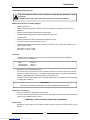
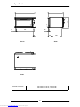
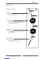
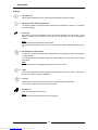
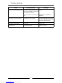
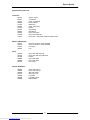
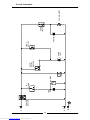
INSTALLATION / OPERATION
MANUAL
E26 CONVECTION OVEN
F23303-6
Downloaded from www.Manualslib.com manuals search engine
MANUFACTURED BY
Moffat Limited
P O Box 10-001
Christchurch
New Zealand
Ph:
(03) 3891-007
Fax:
(03) 3891-276
WORLD-WIDE BRANCHES
UNITED KINGDOM
Blue Seal
Units 6-7, Mount Street Business Park
Mount Street, Nechells
Birmingham B7 5 QU
Ph:
(121) 327-5575
Fax:
(121) 327-9711
UNITED STATES
Moffat Inc
3765 Champion Blvd
Winston-Salem
North Carolina 27115
Ph:
(336) 661 0257
Fax:
(336) 661 9546
CANADA
Lessard Agencies Ltd
P O Box 97
Stn D Toronto
Ontario M6P3J5
Ph:
(416) 766-2764
Fax:
(416) 760-0394
NEW ZEALAND
Christchurch
Moffat Limited
P O Box 10-001
16 Osborne Street
Christchurch
Ph:
(03) 3891-007
Fax:
(03) 3891-276
Auckland
Moffat Limited
4 Waipuna Road
Mt Wellington
Auckland
Ph:
(09) 574-3150
Fax:
(09) 574-3159
AUSTRALIA
Victoria
Moffat Pty Limited
740 Springvale Road
Mulgrave, Melbourne
Victoria 3171
Ph:
(03) 9518-3888
Fax:
(03) 9518-3838
New South Wales
Moffat Pty Limited
8/142 James Ruse Drive, Rose Hill
P O Box 913, Smithfield
Sydney, N.S.W. 2142
Ph:
(02) 8833 4111
Fax:
(02) 8833 4133
Western Australia
Moffat Pty Limited
P O Box 689
Joondalup Business Centre
WA 6027
Ph:
(09) 305-8855
Fax:
(09) 308-8838
Queensland
Moffat Pty Limited
30 Prosperity Place
Geebung, Brisbane
Queensland 4034
Ph:
(07) 3215-9155
Fax
(07) 3215-9170
Downloaded from www.Manualslib.com manuals search engine
South Australia
Moffat Pty Limited
28 Greenhill Road
Wayville
South Australia 5034
Ph:
(08) 8274 2116
Fax:
(08) 8274 2129
Contents
Introduction ....................................................................................................... 2
Installation ......................................................................................................... 3
Before Connection
Location
Electrical Connection
Before Use
Specifications .................................................................................................... 4
Operation ........................................................................................................... 5
Description of Controls
Baking
Cleaning ............................................................................................................. 7
Trouble Shooting............................................................................................... 8
Spare Parts ........................................................................................................ 9
Circuit Schematic ............................................................................................ 10
Date Purchased ................................................................ Serial No ..........................................................
Dealer ...........................................................................................................................................................
Service Agent................................................................................................................................................
1
Downloaded from www.Manualslib.com manuals search engine
Introduction
We are confident that you will be delighted with your TURBOFAN OVEN, and it will become a most valued
appliance in your commercial kitchen.
A new oven can seem very complex and confusing at first glance. To ensure you receive the utmost
benefit from your new Turbofan, there are two important things you can do.
Firstly
Please read the instruction book carefully and follow the directions given. The time taken will be well
spent.
Secondly
If you are unsure of any aspect of the installation, instructions or performance of your oven, contact your
E26 dealer promptly. In many cases a phone call could answer your question.
2
Downloaded from www.Manualslib.com manuals search engine
Installation
Installation Requirements
It is most important that this oven is installed correctly and that operation is correct
before use.
Installation shall comply with local electrical, health and safety requirements.
Before Connection to Power Supply
•
Remove all packing.
•
Check equipment and parts for damage. Report any damage immediately to the carrier and
distributor.
•
Remove protective plastic coating from the side panels.
•
Check that the following parts have been supplied with your oven:
2 x Oven racks
•
Report any deficiencies to the distributor who supplied the oven.
•
The oven’s feet should be pre-fitted to the oven.
•
Check that the available power supply is correct to that shown on the rating plate located on the
right -hand side panel.
240 Volts A.C. 50 Hz, 2.4 kW
220 Volts A.C. 50 Hz, 2.4 kW
Location
•
To ensure correct ventilation for the motor and controls the following minimum installation
clearances are to be adhered to:
Rear
Left-hand side
Right-hand side
25mm / 1”
25mm / 1”
25mm / 1”
•
Position the oven in its working position.
•
Use a spirit level to ensure oven is level from side to side and front to back. (If this is not carried
out, uneven cooking could occur). The feet/legs used with bench/floor mounting or provided with
stands are adjustable and will require adjusting in levelling the unit.
•
The unit should be positioned such that the operating panel and oven shelves are easily reachable
for loading and unloading.
Important:
THE VENT LOCATED ON THE OVEN TOP MUST NEVER BE OBSTRUCTED.
Electrical Connection
•
Ensure unit is fitted with appropriate cord and plug.
•
To access the electrical connection terminal block, grounding lug (marked with green), and strain
relief, remove the back panel (4 screws).
WARNING - THIS APPLIANCE MUST BE GROUNDED
Before Use
•
Operate the oven for about 1 hour at 200°C (400°F) to remove any fumes or odours which may be
present.
3
Downloaded from www.Manualslib.com manuals search engine
Specifications
668
430
885
1
E
1
791
47
E
45
120
179
Front
395
Side
1
E
Plan
Electrical Connection
240 Volts A.C. 50 Hz, 10A, 2.4 kW
220 Volts A.C. 50 Hz, 11A, 2.4 kW
4
Downloaded from www.Manualslib.com manuals search engine
Operation
Operation Guide
Description of Controls
26
Power
Depress to switch power on or off (switch
illuminates when power is on).
°C
50
Thermostat
250
Temperature range 50 - 250°C (120 - 480°F).
Indicator illuminates when the elements are cycling
ON to maintain set temperature.
100
200
150
0
60
5
Bake Timer
1 Hour bake timer.
(Indicator illuminates when “time up” (0) reached,
and buzzer sounds).
10
50
15
40
20
30
Light Switch
Push switch to activate light.
(Light illuminates while button depressed).
5
Downloaded from www.Manualslib.com manuals search engine
Operation
Baking
1. Turn power on
Power switch illuminates when it is depressed and latched in the down position.
2. Set thermostat to desired temperature
The heating indicator light will illuminate whenever the elements are cycling on to maintain
the set temperature.
3. Load oven
Once the oven is up the temperature, open the door and load the oven with product. Avoid
delays in loading the oven with the door open as this will delay the oven’s temperature
recovery.
Note:
The oven light will illuminate with the door open.
The oven’s fan will remain on when the door is opened, as will the heating element (if cycling
on).
4. Set bake timer to desired time
To set timer, turn knob clockwise to the required time. At any stage, the time can be adjusted
in either direction.
For settings less than 10 minutes, first set to greater setting, then turn down to the required
time period.
Note:
This 60 minute timer is completely independent of the oven control.
5. Light
To view the product while baking, depress the light switch on the control panel. The light will
stay on only while the switch is depressed.
6. Time up.
When the timer reaches 0 minutes the buzzer sounds and indicator illuminates.
To cancel the buzzer turn the timer to the off position.
7. Unload oven
Open the door and unload the oven .
Note:
The oven light will illuminate when the door is opened
6
Downloaded from www.Manualslib.com manuals search engine
Cleaning
Cleaning Guidelines
Caution:
ALWAYS TURN OFF THE POWER SUPPLY BEFORE CLEANING.
THIS UNIT IS NOT WATER PROOF.
DO NOT USE WATER JET SPRAY TO CLEAN INTERIOR OR EXTERIOR OF THIS UNIT.
Exterior
Clean with a good quality stainless steel cleaning compound. Harsh abrasive cleaners may damage
the surface.
Interior
Ensure that the oven chamber is cool. Do not use wire brushes, steel wool or other abrasive materials.
Clean the oven regularly with a good quality oven cleaner. Take care not to damage the fan or the
tube at the right side of the oven which controls the thermostat.
Bottom Baffle
To remove, lift up the tray at the front and pull forward out of the oven.
Oven Racks
To remove, slide out to the stop position, raise the front edge up, and lift out.
Side Racks
Loosen the thumbscrew at the rear of each side rack. Undo and remove the thumbscrew at the front
of each side rack. Remove side racks. To replace, engage rack on rear thumbscrew, and refit
thumbscrews at front. Tighten at front and rear.
Fan Baffle
To remove, undo thumbscrew (anti-clockwise rotation) at top of baffle and remove. Lift baffle out from
rear of oven by tilting forward while lifting out of location studs at baffle base. Replace in reverse order.
Oven Seals
To remove, hold at their centre point and pull forward until they unclip. Remove side seals first, then
top and bottom. The seals may be washed in the sink, but take care not to cut or damage them.
To replace, have the lip facing the oven opening. Fit the top and bottom seals first, then the side
seals.
Oven Door Glass
Clean with conventional glass cleaners
7
Downloaded from www.Manualslib.com manuals search engine
Trouble-shooting
Fault
Possible Cause
Remedy
The oven does not operate / start. The mains isolating switch on the Turn on.
wall, circuit breaker or fuses are
“off” at the power board.
The power switch on the oven is Depress switch. Switch will
off.
illuminate.
Bake timer does not time down.
Bake timer not set correctly.
For settings less than 10 minutes,
first set to greater setting then
turn back to desired setting.
Oven light not illuminating.
Blown bulb.
Replace bulb.
Slow recovery
Overloading of oven
Reduce batch size
8
Downloaded from www.Manualslib.com manuals search engine
Spare parts
Replacement part list
Controls
021473
023211
021472
020849
011760
020823
011794
021474
003004
003002
013520
013521
Switch - power
Thermostat
Knob - thermostat
Neon indicator
Bake timer
Knob - bake timer
Buzzer
Light switch
Microswitch
Oven lamp glass
Oven lamp assembly
Oven lamp - 240V 40W miniature Edison screw
Motor & Elements
023371
023372
013431
022042
Oven fan element—240V (2400W)
Oven fan element—220V (2400W)
Fan motor
Fan
023099
023192
021468
023064
023065
023218
Oven door seal strip side
Oven door seal strip top/bottom
Handle
Door outer glass
Door inner glass
Door hinge
Door
Racks & Baffles
024835
024836
023068
023273
023382
023068
004869
Oven side rack LH
Oven side rack RH
Side rack screw
Wire oven rack
Fan baffle
Fan baffle screw
Bottom baffle
9
Downloaded from www.Manualslib.com manuals search engine
Downloaded from www.Manualslib.com manuals search engine
10
E
L2
L1
2
4
1
3
N
POWER
SWITCH
Ø
TIME
UP
2
1
3
B
1Hr
TIMER
BUZZER
FAN
NO
NC
DOOR
MICRO
SWITCH
OVEN
LIGHT
HEATING
LIGHT
SWITCH
OVEN
T/STAT
1
P
FAN ELEMENT
Circuit schematic
11
12
Downloaded from www.Manualslib.com manuals search engine
13
14
Downloaded from www.Manualslib.com manuals search engine