1
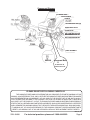
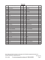
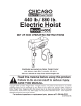
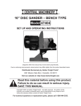
AIR COMPRESSOR
2 HP - 8 GALLON
40400
ASSEMBLY & OPERATING INSTRUCTIONS
Diagrams within this manual may not be drawn proportionally.
Due to continuing improvements, actual product may differ slightly from the product described herein.
Distributed exclusively by Harbor Freight Tools®.
3491 Mission Oaks Blvd., Camarillo, CA 93011
Visit our website at: http://www.harborfreight.com
Read this material before using this product.
Failure to do so can result in serious injury.
Save this manual.
Copyright© 1999 by Harbor Freight Tools®. All rights reserved. No portion of this manual
or any artwork contained herein may be reproduced in any shape or form without the
express written consent of Harbor Freight Tools.
For technical questions or replacement parts, please call 1-800-444-3353.
Rev 01h, 09c
Specifications
Motor
Air Tank
Pump Type
Max. Working Pressure
Air Flow
Press Switch
Materials
Piston Diameter
Cylinder Honing
Overall Dimensions
Outlet Fittings
Single Phase, 120 V~, 60 Hz, 15.5 A, 3,360 RPM
8 Gallon
Single Stage
115 PSI
6 SCFM at 40 PSI, 5 SCFM at 90 PSI,
4.2 SCFM at 115 PSI
70 PSI
Cast Iron Piston and Connecting Rod
Cast Aluminum Crankcase
1.886”
45° Crosshatch
26” x 11-3/4” x 27”
1/4” – 18 NPT
SAVE THIS MANUAL
You will need this manual for the safety warnings and precautions, assembly, operating, inspection,
maintenance and cleaning procedures, parts list and assembly diagram. Keep your invoice with this manual.
Write the invoice number on the inside of the front cover. Keep this manual and invoice in a safe and dry place
for future reference.
GENERAL SAFETY WARNINGS AND PRECAUTIONS
1.
KEEP WORK AREA CLEAN AND DRY. Cluttered, damp, or wet work areas invite injuries.
2.
KEEP CHILDREN AWAY FROM WORK AREA.
Do not allow children to handle this product.
8.
INDUSTRIAL APPLICATIONS MUST FOLLOW OSHA REQUIREMENTS.
3.
STORE IDLE EQUIPMENT. When not in use,
tools and equipment should be stored in a dry
location to inhibit rust. Always lock up tools and
equipment, and keep out of reach of children.
9.
STAY ALERT. Watch what you are doing at all
times. Use common sense. Do not use this
product when you are tired or distracted from
the job at hand.
4.
DO NOT USE THIS PRODUCT IF UNDER
THE INFLUENCE OF ALCOHOL OR DRUGS.
Read warning labels on prescriptions to determine if your judgement or reflexes are impaired
while taking drugs. If there is any doubt, do not
attempt to use this product.
10.
5.
USE EYE AND HAND PROTECTION. Wear
ANSI-approved safety impact goggles and
heavy-duty work gloves when using this product.
CHECK FOR DAMAGED PARTS. Before
using this product, carefully check that it will
operate properly and perform its intended function. Check for damaged parts and any other
conditions that may affect the operation of this
product. Replace or repair damaged or worn
parts immediately.
11.
REPLACEMENT PARTS AND ACCESSORIES: When servicing, use only identical
replacement parts. Only use accessories
intended for use with this product. Approved
accessories are available from Harbor Freight
Tools.
12.
MAINTAIN THIS PRODUCT WITH CARE.
Keep this product clean and dry for better and
safer performance.
6.
7.
DRESS SAFELY. Do not wear loose clothing or jewelry, as they can become caught in
moving parts. Wear a protective hair covering
to prevent long hair from becoming caught in
moving parts. If wearing a long-sleeve shirt,
roll sleeves up above elbows.
and balance at all times to prevent tripping,
falling, back injury, etcetera.
DO NOT OVERREACH. Keep proper footing
REV 01j; 03h; 09c
SKU 40400
For technical questions, please call 1-800-444-3353.
Page 2
13.
14.
15.
MAINTENANCE: For your safety, service and
maintenance should be performed regularly by
a qualified technician.
USE THE RIGHT TOOL FOR THE JOB. Do
not attempt to force a small tool or attachment
to do the work of a larger industrial tool. There
are certain applications for which this tool was
designed. It will do the job better and more
safely at the rate for which it was intended. Do
not modify this tool, and do not use this tool for
a purpose for which it was not intended.
WARNING: Make sure to fill the Air Compressor with a premium quality, 30-weight,
non-detergent oil before each use. Running
the Air Compressor with no oil or low oil will
cause damage to the equipment. Note: The oil
reservoir has an optimal capacity of 30 ounces
of oil.
16.
WHEN CHECKING THE OIL LEVEL: Make
sure to unscrew (do not pull) the Dip Stick
out.
17.
MAKE SURE ALL TOOLS AND EQUIPMENT
USED WITH THE AIR COMPRESSOR ARE
RATED TO THE APPROPRIATE CAPACITY.
Do not use any tool or equipment that does not
operate at the regulator setting being used.
18.
DRAIN AIR COMPRESSOR EVERY DAY. Do
not allow moisture to build up inside the Air
Compressor.
(See “INSPECTION, MAINTENANCE, AND
CLEANING” section of this manual.)
19.
MAINTAIN A SAFE WORKING ENVIRONMENT. Keep the work area well lit. Make sure
there is adequate surrounding workspace. Do
not use the Air Compressor in areas near flammable chemicals, dusts, and vapors.
20.
AVOID INJURY: Never direct the air stream at
people or animals.
21.
DO NOT ALTER OR REMOVE THE FACTORY
SEALED PRESSURE RELEASE VALVE.
22.
To reduce the risk of fire or explosion, never spray flammable liquids
in a confined area. Do not smoke while
spraying. Do not spray where sparks or flames
are present. Keep compressor as far from
SKU 40400
spray area as possible.
22.
DO NOT OPEN THE WATER DRAIN VALVE
SO THAT MORE THAN FOUR THREADS ARE
SHOWING.
23.
An extension cord must never be
used with this item. Connecting this
item to an outlet through an extension
cord may cause electrical damage
to the motor and could present a fire
hazard.
24.
THIS COMPRESSOR MAY REQUIRE A
DEDICATED ELECTRICAL CIRCUIT AS THE
AMPERAGE DRAW UNDER FULL LOAD
COMBINED WITH USE OF ANY OTHER ITEM
MAY OVERLOAD YOUR CIRCUIT.
25.
The brass components of this product contain
lead, a chemical known to the State of California to cause birth defects (or other reproductive
harm). (California Health & Safety code §
25249.5, et seq.)
26.
WARNING: People with pacemakers should
consult their physician(s) before using this
product. Operation of electrical equipment in
close proximity to a heart pacemaker could
cause interference to or failure of the pacemaker.
27.
Never weld on the air tank of this Compressor. Welding of the tank could affect tank
strength and result in an extremely hazardous
condition.
28.
To decrease the potential for electric shock,
never use this Compressor outdoors when
it is raining, and never use the Compressor
on a wet surface.
29.
Not suitable for breathing air supply purposes.
30.
WARNING: The warnings, precautions, and
instructions discussed in this manual cannot
cover all possible conditions and situations that
may occur. The operator must understand that
common sense and caution are factors, which
cannot be built into this product, but must be
supplied by the operator.
For technical questions, please call 1-800-444-3353.
Page 3
Unpacking
When unpacking, check to make sure all parts are included. Refer to the Assembly Drawing and Parts
List at the end of this manual. If any parts are missing or broken, please call Harbor Freight Tools at the number
on the cover of this manual as soon as possible.
Note: There is a square black plastic shipping insert that is placed between the Shroud and the Cylinder
Head. You must remove it before turning on the compressor. See Assembly Diagram page 8.
Assembly
The Wheels need to be assembled to the Air Compressor. Insert the Axle (54) through one of the Wheels
(55). With these two assembled together, insert Axle (54) through the bracket on the bottom of the Tank Assembly
(50). Slide on Washer (56) and the Lock Washer (57) and tighten with the Nut (58). Once assembled, roll the
Air Compressor to test the operation of the wheels. Periodically check to insure that wheel and axle hardware
is secure. Next connect the Rubber Foot (52) to the compressor. Secure it using Bolt (51), Washer (60), and Nut
(61). See Assembly Diagram page 8.
Before Operation Check
To assist you with operation, please refer to the Assembly Diagram and Parts List located on pages 6, 7 and
8.
Warning: Fill with compressor oil before using;
running with NO OIL or LOW OIL voids warranty.
Checking the Oil
Make certain to add compressor oil prior to operation. The Oil Fill Plug and Oil Sight is shown on the
illustration on page 6. Only use a good quality, 30-weight, non-detergent compressor oil.
Change the oil after every 500 hours of operation.
1.
By checking the level of fluid in the Oil Sight (20), you will be able to determine the oil level. The oil
level should be even with the dot in the center of the Oil Sight (20). If low, add oil until it is at the proper
level.
2.
Oil is added by removing the Oil Plug (14) and, using a funnel to avoid spills, adding oil to the Compressor.
After Oil is added, replace the Oil Plug.
Operation
1.
Plug the power cord into an electrical outlet with a grounding prong.
2.
Pull up on the Power switch to turn on (see illustration on page 6). Push down on the switch to turn the
compressor off.
3.
Allow the tank to fill to 80 PSI before using. With the Air Compressor on, its operation is automatic and
under the control of the internal pressure switch.
Warning: Do not remove the factory sealed Air Control Valve (see illustration on page 6); removal of
this valve voids warranty.
Hose Connections
1.
Close the Air Control Valve (turn to right or left).
2.
Connect the high pressure air hose to the air outlet. The outlet is 1/4” NPT. Note: For easy connection
or removal, a quick coupler (not included) should be installed on the end of the outlet.
3.
Turn the Air Control Valve to the middle position to allow the air to pass.
SKU 40400
For technical questions, please call 1-800-444-3353.
REV 06c, 07h
Page 4
Operation (continued)
WARNING! The automatic Pressure Switch (46) is factory set. It should only be adjusted to have the
original settings restored and this should only be done by a qualified technician. Adjustments made
by unqualified personnel or adjusting the pressure valve to other settings will void the warranty
and may cause damage to the compressor or PERSONAL INJURY.
The Safety Valve
The Safety Valve (see illustration on page 6 for location) is used as a backup to help prevent the tank
from exceeding its maximum safe pressure. Check before each use as follows: Pull on the Safety Valve ring to
release pressure; the valve is spring-loaded and has resistance, but it should move without sticking.
Empty Air and Condensation
The Petcock (53) release valve is located underneath the Tank Assembly (50). It must be used daily to
release all trapped air and moisture through this valve. It will also get rid of any condensation that may cause
tank corrosion.
Warning: Do not open the Petcock (53) so that more than four threads are showing.
1.
Push down on the Power switch to turn the compressor off.
2.
Unscrew the Petcock (53) two to three turns only.
3.
When all pressure is released, close the Petcock (53) again.
NOTE: If the Compressor suddenly shuts off, check and reset the unit’s
Overload Protection (59). Ensure that an extension cord is not being used.
REV 06a
SKU 40400
For technical questions, please call 1-800-444-3353.
Page 5
Component Diagram
SHROUD
CYLINDER HEAD
FILTER SCREW
HANDLE
AIR PRESSURE SWITCH
REGULATED VALVE
DRAIN VALVE
AIR Control Valve
AIR PRESSURE METER
AIR PRESSURE METER
Safety Valve
TANK ASSEMBLY
Hex Head Bolt
11
To drain the oil
remove this bolt.
PLEASE READ THE FOLLOWING CAREFULLY
THE MANUFACTURER AND/OR DISTRIBUTOR HAS PROVIDED THE PARTS DIAGRAM IN THIS
MANUAL AS A REFERENCE TOOL ONLY. NEITHER THE MANUFACTURER NOR DISTRIBUTOR MAKES
ANY REPRESENTATION OR WARRANTY OF ANY KIND TO THE BUYER THAT HE OR SHE IS QUALIFIED TO MAKE ANY REPAIRS TO THE PRODUCT OR THAT HE OR SHE IS QUALIFIED TO REPLACE
ANY PARTS OF THE PRODUCT. IN FACT, THE MANUFACTURER AND/OR DISTRIBUTOR EXPRESSLY
STATES THAT ALL REPAIRS AND PARTS REPLACEMENTS SHOULD BE UNDERTAKEN BY CERTIFIED
AND LICENSED TECHNICIANS AND NOT BY THE BUYER. THE BUYER ASSUMES ALL RISK AND LIABILITY ARISING OUT OF HIS OR HER REPAIRS TO THE ORIGINAL PRODUCT OR REPLACEMENT PARTS
THERETO, OR ARISING OUT OF HIS OR HER INSTALLATION OF REPLACEMENT PARTS THERETO.
REV 06c, 09c
SKU 40400
For technical questions, please call 1-800-444-3353.
Page 6
Parts List
Part
1
2
3
4
5
6
7
8, 8-1
8-2
9
10
11
12
13
14
15
16
17
18
19
20
21
22
23
24
25
26
27
28
29
30
Description
Qty
Part
Description
Qty
Socket Screw
4
30
Capacitor
1
Cylinder Head
Cylinder Head Gasket
Valve
Cylinder Gasket
Cylinder
Gasket
Compression Ring
Piston
Wrist Pin Piston
Piston
Hex Head Nut
Crossed Screw
Handle
Oil Retainer
Connecting Rod
Gasket Crankcase
Hex Head Bolt
End Cover Assembly
Washer
Oil Sight
Stem Ring
Washer
Crankshaft Cone Assy
Inner Hex Head Bolt
Crank Case
Cross-head Self-tapping Screw
Motor Drive
Nut
Washer
Capacitor
1
1
1
1
1
1
2
1
1
1
1
4
1
1
1
1
6
1
1
1
1
1
1
1
1
1
1
1
1
1
31
32
33
34
35
36
37
38
39
40
41
42
43
44
45
46
47
48
49
50
51
52
53
54
55
56
57
58
59
60
Back Cover
Forced Air Fan
Stem Ring
Shroud
Stem Ring
Pin
Strip Valve
Filter/Filter Screw
Elbow, 90°
Drain Tube
Check Valve
Tube
Drain Valve
Regulated Valve
Outlet
Air Pressure Switch
Air Pressure Meter
Air Pressure Meter
Safety Valve
Tank Assy
Bolt
Rubber Foot
Petcock
Axle
Wheel
Washer
Lock Washer
Nut
Overload Protection
Washer
1
1
1
1
2
2
1
1
1
1
1
1
1
1
1
1
1
1
1
1
1
1
1
2
2
2
2
2
1
1
61
Nut
1
Note: Some parts listed and shown on this page are for illustration purposed only and are not
available individually as replacement parts.
REV 06a; 07h; 09c
SKU 40400
For technical questions, please call 1-800-444-3353.
Page 7
Assembly Diagram
60
61
SKU 40400
For technical questions, please call 1-800-444-3353.
REV 06a; 07h
Page 8
Limited 1 Year warranty
Harbor Freight Tools Co. makes every effort to assure that its products meet high quality and durability
standards, and warrants to the original purchaser that this product is free from defects in materials and
workmanship for the period of one year from the date of purchase (90 days if used by a professional contractor
or if used as rental equipment). This warranty does not apply to damage due directly or indirectly, to misuse,
abuse, negligence or accidents, repairs or alterations outside our facilities, normal wear and tear, or to lack of
maintenance. We shall in no event be liable for death, injuries to persons or property, or for incidental, contingent,
special or consequential damages arising from the use of our product. Some states do not allow the exclusion or
limitation of incidental or consequential damages, so the above limitation of exclusion may not apply to you. This
warranty is expressly in lieu of all other warranties, express or implied, including
the warranties of merchantability and fitness.
To take advantage of this warranty, the product or part must be returned to us with transportation charges
prepaid. Proof of purchase date and an explanation of the complaint must accompany the merchandise. If our
inspection verifies the defect, we will either repair or replace the product at our election or we may elect to refund
the purchase price if we cannot readily and quickly provide you with a replacement. We will return repaired
products at our expense, but if we determine there is no defect, or that the defect resulted from causes not within
the scope of our warranty, then you must bear the cost of returning the product.
This warranty gives you specific legal rights and you may also have other rights which vary from state
to state.
3491 Mission Oaks Blvd. • PO Box 6009 • Camarillo, CA 93011 • (800) 444-3353
REV 09c
SKU 40400
For technical questions, please call 1-800-444-3353.
Page 9