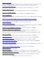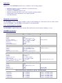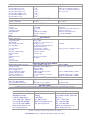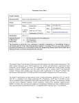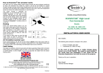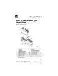
1
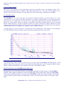
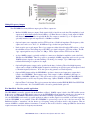
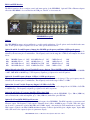
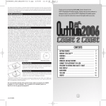
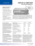
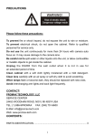
GPS10RBN - 10 MHz, GPS Disciplined
Rubidium Frequency Standard
Key Features
•
•
•
•
•
Completely self-contained unit. No extra P.C
needed. Full information available via LCD.
Rubidium Oscillator locked to GPS satellite signal.
Accuracy to parts in 10-13 (Stratum 1 performance)
Free run mode. Rubidium still gives an accurate
output without a GPS satellite signal (Stratum 1)
Two 1 pps time outputs. Typical error < 20 ns
compared to UTC. Jitter < 300 ps
Low Phase Noise, e.g. -133 dBc/Hz at 10Hz
•
•
•
•
•
•
•
Multiple 10 MHz Outputs plus other outputs
Windows software with full control and monitoring of
the GPS10RBN via RS232, USB, Ethernet or the web.
19” 2U high rack mountable case (GPS10RBN) or
bench mount unit (GPS10R)
Very Low Microphonics
Many options. See list of options in this brochure.
Custom built options available upon request
High quality design
General Description
The GPS10RBN is a 10 MHz, GPS disciplined, rubidium frequency standard. It combines the short-term stability of an
atomic rubidium oscillator with the long-term stability and traceability of the Global Positioning Service (GPS) set of
satellites. The GPS10RBN achieves short and long-term frequency accuracy of parts in 10-13. Thus the GPS10RBN
exceeds the requirements of a Stratum 1 level frequency standard.
Options for the GPS10RBN include 5, 10 or 15 isolated sinewave outputs, an antenna amplifier or fiber optic GPS link,
enabling the antenna to be placed up to 1 km from the GPS10RBN, various fixed high frequency outputs, alarm relay
outputs, redundancy, battery backup supply, time code outputs and a variable frequency output.
Rubidium for the price of an OXCO Oscillator
The GPS10RBN incorporates an atomic rubidium oscillator as the main frequency reference, but costs the same as some
competitive units that use less accurate crystal oscillators. The rubidium used in the GPS10RBN is 30 times more stable
than any OXCO available. Therefore the GPS10RBN achieves a frequency stability of typically 7 x 10-13 in 1000 sec.
Frequency Standards that use a crystal oscillator as the main reference can only achieve this stability when measurements
are averaged over one week or one month. This enables the GPS10RBN to be used as a frequency reference for
GPS10RBN Brochure. © Precision Test Systems Ltd 1997 - 2011
frequency counters etc and measurements can be made in seconds, not days or weeks as is the case for crystal oscillator
based units.
Accurate Timing Outputs
There are two 1 pps (pulse per second) outputs that are derived from the GPS receiver or the rubidium oscillator. The 1
pps signal from the GPS receiver is aligned to UTC with less than 20 ns error. The 1 pps from the rubidium is also
aligned to UTC but has the advantage of less than 300 ps jitter. Most other frequency standards quote 50-100 ns.
Very Low Phase Noise
The GPS10RBN is one of the lowest phase noise frequency standards available, at any price! Phase noise is often
overlooked, but is one of the most important specifications of a frequency standard. Many of today's high performance
signal generators, for example, have very low phase noise outputs. These signal generators have their own internal, low
phase noise, crystal oscillator. However, if this type of instrument is used with an external frequency source, it is essential
that the external frequency source has an equally low phase noise output as the internal oscillator. Otherwise the signal
generators phase noise may be impaired. Of course it's not only signal generators that could suffer, but also any other type
of instrument that relies on a low phase noise frequency source, to operate correctly.
A typically phase noise plot is shown below. The blue line is the specification line. The black line is the actual phase
noise. The light blue are the line frequency spurs typical with any measurement that is AC powered.
Keyboard Control and LCD Display
A 16-way keyboard is used to interface to three microprocessors that control the GPS10RBN. The LCD display's over 50
different menus. These menus show all the relevant information including time, position (longitude, latitude, height),
number of satellite tracked, health of each satellite and the status of the rubidium oscillator.
Allan Deviation Plot of the GPS10RBN and the GPS signal
The diagram below shows the Allan deviation of a typical GPS signal (pink), the Allan deviation of the GPS10RBN's
rubidium oscillator when free running (not locked to the GPS signal) (yellow) and the actual output of the GPS10RBN
when locked to the GPS signal (blue). As can be seen, the GPS10RBN combines the short-term stability of the rubidium
oscillator with the long-term stability of the GPS signal to achieve short and long term stability of its frequency output
signal.
GPS10RBN Brochure. © Precision Test Systems Ltd 1997 - 2011
Multiple Frequency Outputs
The GPS10RBN has many different output options. These outputs are:
•
Buffered 10 MHz sinewave outputs. Each output is fully isolated from each other. The amplitude of each
output can be individually adjusted from 0 dBm to +13 dBm. Reverse isolation of each output is 130 dB
and channel to channel isolation is typically 90 dB. Five outputs as standard. Up to 15 outputs can be
optionally installed. Optional output level to +20 dBm is available.
•
Optional square wave output that can drive TTL levels into a 50 Ω load impedance. The frequency of the
square wave can be set to 10, 5, 2, 1, 0.1 MHz and 1 pps via the front panel keyboard.
•
Dual one pulse per second outputs. These 1 pps outputs are either derived from the GPS receiver, or from
the rubidium receiver. The leading edge of the GPS 1 pps signal is aligned to UTC time ± 20 ns. The Rb
1 pps output signal has very low jitter of < 300 ps. These outputs can drive TTL levels into 50 Ω.
•
A slave 10 MHz output is optionally available to connect more distribution amplifiers, such as the DA1100-10 to the GPS10RBN. Thus it is possible to get multiple 10 MHz outputs that can be used to provide
10 MHz reference signals to an entire building or workshop, for example. Up to 1000 outputs can be
realized all delivering a low phase noise output.
•
Optional high frequency outputs can be specified at the time of ordering. These fixed high frequency
outputs can be as high at 10 GHz (higher frequencies available upon special request) and are phase locked
to the main frequency reference. Note: this option only generates one fixed frequency.
•
Optional DDS Output enables the GPS10RBN to produce a sinewave and squarewave output that is
locked to the GPS10RBN. The frequency range of this output is 1 µHz to 80 MHz (1 µHz steps) or
10µHz to 1640 MHz (10 µHz steps). This option can be used to generate the popular 2048 kHz and 13
MHz frequencies as well as any frequency in the range 1 µHz to 80 MHz or 10 µHz to 1640 MHz.
•
Optional Time Code Output. This option generates the industry standard IRIG-B, IRIG-E and ESE-TC90
time code formats. Also a 48 bit BCD time code can be generated with option 16.
Free Run Mode. Ideal for portable applications
The GPS10RBN is normally operated with the Rubidium oscillator's 10 MHz output, locked to the GPS satellite system.
In the event of a failure of the GPS signal for any reason, the GPS10RBN will automatically switch over to free run mode.
In this mode, the GPS10RBN's Rubidium Oscillator still achieves Stratum 1 performance over a 72 hour period.
Also the GPS10RBN can be used for portable applications where a satellite signal is not available, or the time required to
lock the GPS10RBN is not available. When the GPS10RBN is powered up it can be set to the free run mode. The
Rubidium Oscillator "remembers" the last known good frequency setting and adjusts itself to this frequency. Thus an
accurate 10 MHz is available within a few minutes of switch on. This mode is ideal for setting up GSM base stations that
require an accurate time base for frequency measurement.
GPS10RBN Brochure. © Precision Test Systems Ltd 1997 - 2011
RS232 and USB Interface
The RS232 interface allows complete control and interrogation of the GPS10RBN. Optional USB or Ethernet adapters
allows the GPS10RBN to be controlled via the USB port of the PC or from a network.
GPS10RBN Rear panel
Options
The GPS10RBN has many options enabling it to work in varied applications. Not all options can be installed at the same
time. Some options require a separate case. Some of the options are listed below:
Option 01 and 02: Second Frequency Output, 0 to 500 MHz spot frequency and 500 to 1 GHz spot frequency
This option gives a second frequency output. The frequency is fixed and cannot be changed. The spot frequency must be
advised by the customer prior to manufacture. The frequency can be in the range 0 to 1 GHz. Some examples are shown
below:
01A
01B
01C
01D
500 MHz Square x 1
100 MHz Sine x 1
10.23 MHz Sine x5
10.24 MHz Sine x 1
01E
01F
01G
01H
10.24 MHz Sine x 5
8.0 MHz Sine x 5
100 MHz Sine ULN
16 MHz Sine ULN
01J
01K
01L
01M
5 MHz Sine x 5
1 MHz Sine x 5
100 kHz Sine x 5
5 MHz x 5 LN
01N
01P
01Q
01R
Option 02Aand option 02B. : Second Variable Frequency Output, 780 to 820 MHz or 800 to 1200 MHz.
This option gives a second frequency output. The frequency is variable and can be changed from 780 MHz to 820 MHz
or 800 - 1200 MHz in 100 kHz steps. The frequency output has good phase noise and low spurious.
Option 03: Second Frequency Output, 1 GHz to 3.2 GHz spot frequency
This option gives a second frequency output. The frequency is fixed and cannot be changed. The spot frequency must be
advised by the customer prior to manufacture. The frequency can be in the range 1 GHz to 3.2 GHz.
Option 03A: Second Variable Frequency Output, 2.25 GHz to 2.65 GHz
This option gives a second frequency output. The frequency is variable and can be changed from 2.25 GHz to 2.65 GHz
in 100 kHz steps. The frequency output has good phase noise and low spurious.
Option 04 and Option 35: Antenna Amplifier /Fiber Optic Link
These options can be used to extend the range between the GPS antenna and the GPS10RBN. Up to 300 m (1000 feet)
can be realized with a cable and amplifier, up to 1 km (3200 feet) with a fiber optic GPS link.
Option 05, 05A and 05B: DDS Signal Generator
Option 05 adds a DDS (direct digital synthesis) signal output to the GPS10RBN. The DDS output has a squarewave and
sinewave output. The frequency of this output is adjustable from 1 µHz to 80 MHz in steps of 1 µHz. Thus, this option
can be used to generate the popular 2048 kHz and 13 MHz outputs, often needed in Telecommunication systems. The
DDS output is locked to the main 10 MHz rubidium frequency oscillator. Option 05A gives a higher output. Option 05B
adds a Sine and Cosine outputs (in place of squarewave output).
GPS10RBN Brochure. © Precision Test Systems Ltd 1997 - 2011
Option 06: RS232 Cable
The RS232 cable connects the GPS10RBN to a PC enabling control and interrogation of the GPS10RBN by the PC.
Option 07, 07A and 07B: Alarm Relay/TTL Output
This option adds an alarm output. Option 07 and 07A add a dual changeover relay that is activated in the event of an
alarm. Each relay contact is rated at 30 VDC and 1 Amp (5A for Option 07A). Option 07B is a TTL output signal only.
Option 08: Redundancy
Option 08 adds redundancy. With this option, two GPS10RBN’s can be configured into a redundancy set-up with five
main 10 MHz outputs (up to 15 outputs optionally available). Normally one unit will supply the 10 MHz outputs (locked
to the GPS satellite). In the event of failure of this unit, the 10 MHz outputs will be automatically switched to the second
GPS10RBN unit. The second GPS10RBN unit will then supply the 10 MHz outputs, locked to the GPS system. Even if
both GPS antennas are disconnected, and one unit completely fails, there will still be a 10 MHz from the second unit
running from the rubidium oscillator. Both units are identical; there is no master or slave. Simply, whatever unit is
healthy will supply the 10 MHz output. System status is available via the RS232 interface. This option is ideal for
applications that require extra security. Extra 10 MHz outputs can be added if required.
Option 09: IRIG-B Output
This option gives the industry standard IRIG-B or IRIG-E time code output. The output can be internally set to give an
AM modulated signal or TTL output.
Option 11: Clock / Date Display Unit
Option 11 provides a remote Clock / Date display. The display consists of a 6 digit 25 mm high digital LED display that
can be read from a distance of 10 meters. The display can be located remotely from the GPS10RBN. The display
requires a cable connection from the GPS10RBN although a wireless unit is available on special order.
Option 12: Additional sinewave outputs
The GPS10RBN has five isolated 10 MHz sinewave outputs. Option 12 adds a further five making ten in total. Option
12C adds a further ten, making fifteen in total.
Option 12A: 10.23 MHz Outputs
This option changes the five sinewave outputs to 10.23 MHz. A rear panel input connector allows the DDS option (option
05) to generate 10.230 MHz and be available on these five isolated outputs.
Option 13: Mute Sinewave Outputs in the event of an alarm
This option disables all the sinewave outputs in the event of an alarm or error.
Option 14: Service manual. The service manual has service information and realignment procedures.
Option 15: Windows Software
This windows software operates on Windows 2000/XP/Vista. It allows all the main parameters of the GPS10RBN to be
monitored and recorded by the PC.
Option 16: BCD Time Code Output
This option gives a 48 bit BCD time code output. The time output is in the format HH:MM:SS.sssssss. The fractional
seconds have a resolution of 100 ns. The output is updated every 100 ns and is accurate to UTC to within 200 ns.
Option 17: DDS Generator 0 to 400 MHz
This option adds a DDS generator that can operate from 0 to 400 MHz in 0.1 Hz steps.
Option 18: Ethernet Port
This option adds an Ethernet port. This allows the GPS10RBN to be controlled and monitored via an Ethernet network or
internet.
GPS10RBN Brochure. © Precision Test Systems Ltd 1997 - 2011
Option 19: +24VDC Input
This option allows the GPS10RBN to be externally powered by a +24 VDC supply at 5 amps. In the event of AC power
being lost, the GPS10RBN will instantly switch over to the external +24 VDC supply (supply not included).
Option 20: 2.048 MHz G703:10 output
This option gives the popular 2.048 MHz output. The output is a squarewave with amplitude of ± 1.2 V in 75 Ω
Option 21: Lightening Protection
This option adds lightening protection to the antenna input. The protection is placed close to the GPS antenna.
Option 22: 0 to 1640 MHz DDS Output
This option adds a DDS output. The output can be set anywhere from 0 to 1640 MHz in 10 µHz steps.
Option 23: GSM Interface
This option enables the GPS10RBN to send a SMS (short message service) or text to ten GSM mobile phones in the event
of an error.
Option 24: Frequency Change to 5 MHz (also requires option 12 additional 5 outputs to be installed)
This option changes all sinewave outputs to 5 MHz instead of 10 MHz. A 10 MHz output is still available.
Option 25: USB Adapter. Allows GPS10RBN to be controlled from a USB port of a PC.
Option 26: Low Phase Noise Option
This option gives a low phase noise output. Normally the frequency is 10 MHz, but any frequency from 1 to 100 MHz
can be supplied. This output is phase locked to the main rubidium output.
Option 28: Control of GPS10RBN over the internet: Ideal for remote monitoring of the GPS10RBN.
Option 30, 30A, 30B: Squarewave and Pulse Outputs
Opt 30: Squarewave Output. Gives a TTL output switchable in frequency to 10, 5, 2, 1, 0.1 MHz and 1 pps.
Opt 30A: 5 x squarewave outputs at 1 MHz (other frequencies available)
Opt 30B: Pulse Output. 5 x pulse outputs, each can be individually set to 1 PPS, 10 PPS, 100 PPS, 1k PPS or 10k PPS
Option 32: Slave Output.
Adds a slave 10 MHz output. This can be used to connect further distribution amplifiers to the GPS10RBN.
Option 33: Carrying Case. A plastic carrying case with foam insert is used to carry and protect the GPS10RBN
Option 34: High Power Outputs. The 10 MHz output levels are increased to a maximum of +20 dBm.
Option 35: Fiber Optic Link for Antenna: Allows GPS Antenna to be located up to 1 km away from GPS10RBN.
Option 36: Fiber Optic 10 MHz Output
This option adds a fiber optic output together with a fiber optic receiver. This allows the 10 MHz output to be routed over
very long distances using fiber optic cable.
Option 37: Guaranteed Phase Noise Specifications: Phase noise plots of every output included.
Option 38: NTP Server: NTP Server Output
Option 39: 2nd RS232 Port: A second RS232 port to be used with various options, freeing up original interface.
Option 40A and 40 B External Locking Inputs: Allows GPS10RBN to be locked to external 10 MHz or 1 pps signals
Option 42: Different Connectors: The standard BNC connectors can be replaced with TNC, SMA or other types
GPS10RBN Brochure. © Precision Test Systems Ltd 1997 - 2011
Applications
Applications of the GPS10RBN include, but are not limited to, the following examples:
•
•
•
•
•
•
Reference frequency source in a calibration or standards laboratory
Portable frequency standard
Calibration of GSM Base Station Clocks
Reference Frequency and Time source for the electricity generating industry
Synchronizing of telecommunication and computer networks
Space Measurements.
High Quality of Construction
The GPS10RBN is made to the highest standards. A purpose built aluminum 19” rack mount case houses all the circuits
inside the GPS10RBN. The GPS10RBN is CE marked for sale within the EEC.
Active Antenna Supplied as Standard
The GPS10RBN is supplied with an active antenna. This small unit can be easily fitted to buildings, roofs etc.
GPS10RBN Specifications
Specification
10 MHz Outputs
Description
Connector
Frequency
Accuracy
Signal Type / Amplitude
Harmonic Distortion / Spurious
Return Loss
Reverse Isolation
Channel to Channel Isolation
Rear panel BNC socket
10 MHz
Refer to Allan Deviation section
Sine wave @ 0 dBm to + 13 dBm
-30 dBc / - 120 dBc (> 0.5 MHz)
> 23 dB @ 10 MHz
> 130 dB
> 90 dB
Remarks
Internally adjustable
Squarewave Output (Option 30 required)
Connector
Frequency
Accuracy
Signal Type
Amplitude (open circuit / 50 ohm)
Rear panel BNC socket
10, 5, 2, 1, 0.1 MHz and 1 pps
Refer to Allan Deviation section
Square wave
0 to 5 V / 2.7 V , TTL Compatible
Connector
Frequency
Signal Type
Amplitude (open circuit)
Amplitude (50 ohm)
Accuracy to UTC time (GPS 1 pps output)
Jitter of Rubidium Osc. 1 pps output
Rear panel BNC socket
1 pulse per second
Pulse Output
0 to 5 V, TTL Compatible
0 to > 2.5 V, TTL Compatible
< 20 ns (6 sigma)
< 300 ps
Connector
Frequency
Accuracy
Signal Type
Amplitude
Harmonic Distortion
Rear panel BNC socket
10 MHz
Refer to Allan Deviation section
Sine wave
> 3 dBm
- 20 dBc
Selectable by keyboard
1 PPS Outputs
After cable delays taken into account
Slave Output (Option 32 required)
Fixed level output
Typically -40 dBc
Phase Noise Response (Guaranteed / Typical). 10 MHz Outputs
At 1 Hz Offset
At 10 Hz Offset
At 100 Hz Offset
At 1 kHz Offset
At 10 kHz Offset
At 100 kHz Offset
-90 / -95 dBc/Hz
-130 / -134 dBc/Hz
-150 / -152 dBc/Hz
-155 / -159 dBc/Hz
-158 / -161 dBc/Hz
-158 / -161 dBc/Hz
Optional to -105 dBc/Hz available
Optional to -140 dBc/Hz available
Optional to -157 dBc/Hz available
Optional to -165 dBc/Hz available
Optional to -168 dBc/Hz available
Optional to -168 dBc/Hz available
GPS10RBN Brochure. © Precision Test Systems Ltd 1997 - 2011
Allan Deviation when locked to GPS Satellites (typical)
< 2 x 10-11
< 1 x 10-11
< 2 x 10-12
< 7 x 10-13
< 6 x 10-13
< 7 x 10-13
< 2 x 10-13
Observation Time 1 seconds
Observation Time 10 seconds
Observation Time 100 seconds
Observation Time 1000 seconds
Observation Time 10000 seconds
Observation Time 100000 seconds
Observation Time 1 week
GPS10RBN in full lock for > 1 week. > 3
satellites in view. Ambient temperature
0 °C to +50 °C. Temperature change less
than 3 °C per hour
Rubidium Drift when GPS10RBN NOT Locked to GPS Satellites
Drift due to aging
Drift due to temperature
< 5 x 10-11 per month
< 5 x 10-11
Number of Channels
Frequency
Acquisition Time
Positioning Accuracy
Jamming Immunity
Antenna
Datum
12 parallel
1575.42 MHz
< 50 s typical
< 25 m
-79 dBm @ 1575.42 MHz
Active micro strip patch
WGS-84
Operating Temperature
Storage Temperature
Magnetic Field
AC Power Inlet with switch
AC Voltage Range
0 °C to +50 °C
-20 °C to +60°C
< 2 x 10E-10 for 1 Gauss field reverse
IEC320 power cord
100 - 240 VAC (usable 90-260 VAC)
100 watts max (warm up)
50 watts typical (operating)
3.15A, 250 VAC slow blow type
482.6 mm x 323 mm
88 mm and 7 kg
After 30 days operation
0 °C to +50 °C
GPS Receiver
Simultaneous operation
L1 Frequency
With current position / time data. No SA
1 sigma, pos hold mode
Measured at active antenna input
Powered by GPS10RBN
Miscellaneous
Power consumption
Fuse rating
Dimensions Width x Depth
Height and weight
Weight
Supplied Accessories
Antenna
Power cord
Instruction manual
Rear Panel
Warm up period is < 10 minutes at +20 °C
Active type, 5V @ 20 mA
IEC320 type
Option 05: DDS Generator Output
Overall Frequency Range / Step Size
Frequency Accuracy
Sinewave Frequency Range
Sinewave Output level
Spurious and Harmonic Output
Squarewave Frequency Range
Squarewave Output Level
Allan deviation (100 second)
1 µHz to 80 MHz in 1 µHz steps
± 300 µHz plus main 10 MHz error
10 kHz to 80 MHz
> 0 dBm into 50 Ω
-40 dBc and -20 dBc respectively
1 µHz to 80 MHz
0V to 3V nominal into open circuit
2.5 x 10⁻¹²
Usable to 90 MHz
Subject to jitter specification
Option > +10 dBm available (opt 05A)
Use 50 ohm termination above 1 MHz
> 0 dBm into 50 Ω (10 kHz – 80 MHz)
Output 09: IRIG Time Code Output
Output types
Mark – Space Ratio (IRIG-B)
Output type (IRIG-B) / Impedance
IRIG-B or IRIG-E or ESE TC-90
3.3 to 1
TTL or AM. 2.7 V p-p / 600 Ω
Internally selectable
Internally selectable
All other options
Consult Precision Test Systems for further details of other options. Not all options can be fitted at the same time.
Head Office - UK
Precision Test Systems LTD
40 Holkham Avenue,
South Woodham Ferrers
Essex, CM3 7AU, England
Tel: +44 (0) 870 368 9608
Fax: +44 (0) 1245 330030
Email: [email protected]
Web: www.ptsyst.com
South Africa
Precision Test Systems cc
Gauteng
South Africa
Fax: 08651 58198
Email: [email protected]
Web: www.ptsyst.com
USA
Precision Test Systems
14781 Memorial Dr, Suite # 981
Houston
Texas, 77079, USA
Tel: 1 888 876 4804
Fax: 1 832 201 6564
Email: [email protected]
Web: www.ptsyst.com
Specifications and features subject to change without notice (290311)
GPS10RBN Brochure. © Precision Test Systems Ltd 1997 - 2011