1
Lighting Control Console
Operations Manual
Version 2.0
C o p y r i g h t © 2 0 1 3 E le c tr o n i c T h e a t r e C o n t r o l s , I n c .
All Rights reserved.
P r o d u c t in f o r m a t i on a n d s p e c i f i c a t i o n s s u bj e c t t o c h a n g e .
P a r t N um b e r : 4 3 1 0 M 1 2 1 0 - 2 . 0 0 R e v A
R e le a s ed : 2 0 1 3 - 0 3
ET C ®, E o s ™ ,E o s T i ™ , G i o ®, I o n ®, E l e m en t ™ , E m p h a s i s ®, E x p r e s s io n ®, In s i g h t ™ , I m a g i n e ™ ,
F o c u s ™ , E x p r e s s ™ , U n i s o n ®, O b s e s s i o n ® II , E T C N e t 2 ™ , E D M X ™ , R e v o l u t i o n ® a n d S e n s o r + ®,
a r e e i t h e r r e g is te r e d tr a d e m a r k s o r t r a d e m a r k s o f E l e c t r o n i c T h e a tr e C o n t r o l s , I n c . i n t h e
U n i t e d S t a t e s a n d o t h e r c ou n t r i e s .
E T C p e r m i ts t h e r e p r o d u c t i o n o f m a t e r i a l s i n t h i s m a n u a l o n l y f o r n o n - c o m me r c i a l p u r p o s e s .
A l l o t h e r r i g ht s a r e r e s e r v e d b y E T C .
E T C i n t e n d s t hi s d o c u m e n t , w h e t h e r p r i n te d o r e l e c t r o n i c , t o b e p r o v i d e d i n i t s e n t i r e ty .
Table of Contents
Introduction . . . . . . . . . . . . . . . . . . . . . . . . . . 1
Using this Manual . . . . . . . . . . . . . . . . . . . . . . . . . . . . . . . . . . . . . . . .2
Register Your Ion . . . . . . . . . . . . . . . . . . . . . . . . . . . . . . . . . . . . . . . .3
Help from ETC Technical Services . . . . . . . . . . . . . . . . . . . . . . . . . .3
Important Concepts . . . . . . . . . . . . . . . . . . . . . . . . . . . . . . . . . . . . . .4
Channel = Fixture . . . . . . . . . . . . . . . . . . . . . . . . . . . . . . . . . . . .4
Output . . . . . . . . . . . . . . . . . . . . . . . . . . . . . . . . . . . . . . . . . . . . .4
Record Target . . . . . . . . . . . . . . . . . . . . . . . . . . . . . . . . . . . . . . .4
Move Instruction . . . . . . . . . . . . . . . . . . . . . . . . . . . . . . . . . . . . .4
Manual Data . . . . . . . . . . . . . . . . . . . . . . . . . . . . . . . . . . . . . . . .4
Syntax Structure . . . . . . . . . . . . . . . . . . . . . . . . . . . . . . . . . . . . .4
Parameters and Parameter Categories . . . . . . . . . . . . . . . . . . . .5
Tracking vs. Cue Only . . . . . . . . . . . . . . . . . . . . . . . . . . . . . . . . .5
Move Fade. . . . . . . . . . . . . . . . . . . . . . . . . . . . . . . . . . . . . . . . . .6
Block vs. Assert . . . . . . . . . . . . . . . . . . . . . . . . . . . . . . . . . . . . . .6
Live and Blind . . . . . . . . . . . . . . . . . . . . . . . . . . . . . . . . . . . . . . .7
HTP vs. LTP . . . . . . . . . . . . . . . . . . . . . . . . . . . . . . . . . . . . . . . .7
Other Reference Materials . . . . . . . . . . . . . . . . . . . . . . . . . . . . . . . . .8
Help System . . . . . . . . . . . . . . . . . . . . . . . . . . . . . . . . . . . . . . . .8
Online Eos Family (Eos Ti, Eos, Gio and Ion) User Forums . . . .8
Chapter 1
System Overview . . . . . . . . . . . . . . . . . . . . . 9
System Components . . . . . . . . . . . . . . . . . . . . . . . . . . . . . . . . . . . .10
Console . . . . . . . . . . . . . . . . . . . . . . . . . . . . . . . . . . . . . . . . . . .10
Remote Processor Unit (RPU). . . . . . . . . . . . . . . . . . . . . . . . . .10
Remote Video Interface (RVI) . . . . . . . . . . . . . . . . . . . . . . . . . .10
Radio Focus Remote (RFR) . . . . . . . . . . . . . . . . . . . . . . . . . . .10
iRFR and aRFR . . . . . . . . . . . . . . . . . . . . . . . . . . . . . . . . . . . . .10
Gateways. . . . . . . . . . . . . . . . . . . . . . . . . . . . . . . . . . . . . . . . . .11
Console Geography . . . . . . . . . . . . . . . . . . . . . . . . . . . . . . . . . . . . .12
Terminology . . . . . . . . . . . . . . . . . . . . . . . . . . . . . . . . . . . . . . . .13
Littlites® . . . . . . . . . . . . . . . . . . . . . . . . . . . . . . . . . . . . . . . . . . . . . . . . . . . . . 14
Cleaning Ion. . . . . . . . . . . . . . . . . . . . . . . . . . . . . . . . . . . . . . . .14
Outputting DMX . . . . . . . . . . . . . . . . . . . . . . . . . . . . . . . . . . . . .14
Console Capacities . . . . . . . . . . . . . . . . . . . . . . . . . . . . . . . . . . . . .15
Output Parameters . . . . . . . . . . . . . . . . . . . . . . . . . . . . . . . . . .15
Channel Counts . . . . . . . . . . . . . . . . . . . . . . . . . . . . . . . . . . . . .15
Cues and Cue Lists . . . . . . . . . . . . . . . . . . . . . . . . . . . . . . . . . .15
Record Targets . . . . . . . . . . . . . . . . . . . . . . . . . . . . . . . . . . . . .15
Faders . . . . . . . . . . . . . . . . . . . . . . . . . . . . . . . . . . . . . . . . . . . .15
1
Chapter 2
System Basics . . . . . . . . . . . . . . . . . . . . . . 17
Setting Up the Hardware . . . . . . . . . . . . . . . . . . . . . . . . . . . . . . . . .18
Power . . . . . . . . . . . . . . . . . . . . . . . . . . . . . . . . . . . . . . . . . . . . . . . .19
Power Up the Console. . . . . . . . . . . . . . . . . . . . . . . . . . . . . . . .19
Power Down the Console . . . . . . . . . . . . . . . . . . . . . . . . . . . . .19
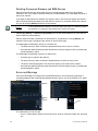
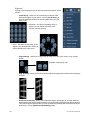
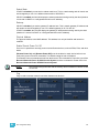
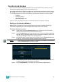
Your First Interaction . . . . . . . . . . . . . . . . . . . . . . . . . . . . . . . . . . . .20
Single Monitor Configuration . . . . . . . . . . . . . . . . . . . . . . . . . . .20
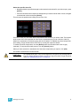
Dual Monitor Configuration . . . . . . . . . . . . . . . . . . . . . . . . . . . .21
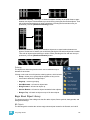
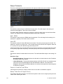
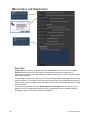
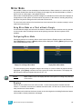
The Central Information Area (CIA) . . . . . . . . . . . . . . . . . . . . . . . . .22
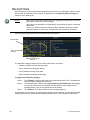
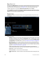
Parameter Display . . . . . . . . . . . . . . . . . . . . . . . . . . . . . . . . . . .22
Browser . . . . . . . . . . . . . . . . . . . . . . . . . . . . . . . . . . . . . . . . . . .22
Collapse/Expand the CIA. . . . . . . . . . . . . . . . . . . . . . . . . . . . . .22
Lock the CIA . . . . . . . . . . . . . . . . . . . . . . . . . . . . . . . . . . . . . . .23
Favorite CIA Display . . . . . . . . . . . . . . . . . . . . . . . . . . . . . . . . .23
Locking the Facepanel. . . . . . . . . . . . . . . . . . . . . . . . . . . . . . . .23
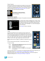
Using the Browser . . . . . . . . . . . . . . . . . . . . . . . . . . . . . . . . . . . . . .24
Virtual Keyboard . . . . . . . . . . . . . . . . . . . . . . . . . . . . . . . . . . . .24
Fader Module. . . . . . . . . . . . . . . . . . . . . . . . . . . . . . . . . . . . . . .25
Using Direct Selects . . . . . . . . . . . . . . . . . . . . . . . . . . . . . . . . .25
Direct Selects in Flexi Mode . . . . . . . . . . . . . . . . . . . . . . . . . . .26
Clear Functions . . . . . . . . . . . . . . . . . . . . . . . . . . . . . . . . . . . . .27
Display Control and Navigation . . . . . . . . . . . . . . . . . . . . . . . . . . . .28
Opening and Closing Displays. . . . . . . . . . . . . . . . . . . . . . . . . .28
Selecting Displays . . . . . . . . . . . . . . . . . . . . . . . . . . . . . . . . . . .29
Moving Displays. . . . . . . . . . . . . . . . . . . . . . . . . . . . . . . . . . . . .29
Scrolling within a Display . . . . . . . . . . . . . . . . . . . . . . . . . . . . . .29
Expanding Displays . . . . . . . . . . . . . . . . . . . . . . . . . . . . . . . . . .30
Zooming Displays . . . . . . . . . . . . . . . . . . . . . . . . . . . . . . . . . . .30
Graphical User Interface (GUI) Display Conventions . . . . . . . . . . . .31
Indicators in the Live/Blind Display . . . . . . . . . . . . . . . . . . . . . .31
[Data] Key . . . . . . . . . . . . . . . . . . . . . . . . . . . . . . . . . . . . . . . . .35
[Time] Key . . . . . . . . . . . . . . . . . . . . . . . . . . . . . . . . . . . . . . . . .35
[Label] Key. . . . . . . . . . . . . . . . . . . . . . . . . . . . . . . . . . . . . . . . .35
Using Flexichannel . . . . . . . . . . . . . . . . . . . . . . . . . . . . . . . . . .36
Indicators in the Playback Status Display . . . . . . . . . . . . . . . . .37
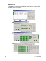
Using [Format] . . . . . . . . . . . . . . . . . . . . . . . . . . . . . . . . . . . . . . . . .39
Encoders . . . . . . . . . . . . . . . . . . . . . . . . . . . . . . . . . . . . . . . . . . . . .45
Encoder Navigation . . . . . . . . . . . . . . . . . . . . . . . . . . . . . . . . . .45
Locking the Encoders . . . . . . . . . . . . . . . . . . . . . . . . . . . . . . . .45
Encoders in Blind. . . . . . . . . . . . . . . . . . . . . . . . . . . . . . . . . . . .45
Flexi Encoders . . . . . . . . . . . . . . . . . . . . . . . . . . . . . . . . . . . . . .45
Moving Light Controls. . . . . . . . . . . . . . . . . . . . . . . . . . . . . . . . . . . .46
ML Controls . . . . . . . . . . . . . . . . . . . . . . . . . . . . . . . . . . . . . . . .46
Using Softkeys . . . . . . . . . . . . . . . . . . . . . . . . . . . . . . . . . . . . . . . . .47
Context Sensitive Softkeys . . . . . . . . . . . . . . . . . . . . . . . . . . . .47
Changing Softkey Pages . . . . . . . . . . . . . . . . . . . . . . . . . . . . . .47
2
Ion Operations Manual
Chapter 3
Managing Show Files . . . . . . . . . . . . . . . . . 49
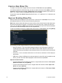
Create a New Show File. . . . . . . . . . . . . . . . . . . . . . . . . . . . . . . . . .50
Open an Existing Show File . . . . . . . . . . . . . . . . . . . . . . . . . . . . . . .50
Selective Partial Show Opening . . . . . . . . . . . . . . . . . . . . . . . .52
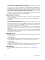
Merging Show Files . . . . . . . . . . . . . . . . . . . . . . . . . . . . . . . . . . . . .54
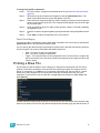
Printing a Show File . . . . . . . . . . . . . . . . . . . . . . . . . . . . . . . . . . . . .55
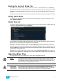
Saving the Current Show File. . . . . . . . . . . . . . . . . . . . . . . . . . . . . .57
Using Quick Save . . . . . . . . . . . . . . . . . . . . . . . . . . . . . . . . . . . . . . .57
Using Save As . . . . . . . . . . . . . . . . . . . . . . . . . . . . . . . . . . . . . . . . .57
Importing Show Files . . . . . . . . . . . . . . . . . . . . . . . . . . . . . . . . . . . .57
Exporting a Show File . . . . . . . . . . . . . . . . . . . . . . . . . . . . . . . . . . .58
Deleting a File . . . . . . . . . . . . . . . . . . . . . . . . . . . . . . . . . . . . . . . . .58
File Manager . . . . . . . . . . . . . . . . . . . . . . . . . . . . . . . . . . . . . . . . . .58
Chapter 4
Patch. . . . . . . . . . . . . . . . . . . . . . . . . . . . . . 59
About Patch . . . . . . . . . . . . . . . . . . . . . . . . . . . . . . . . . . . . . . . . . . .60
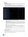
Displays . . . . . . . . . . . . . . . . . . . . . . . . . . . . . . . . . . . . . . . . . . . . . .61
Flexichannel Views in Patch . . . . . . . . . . . . . . . . . . . . . . . . . . .62
Labeling . . . . . . . . . . . . . . . . . . . . . . . . . . . . . . . . . . . . . . . . . . .62
Patching Conventional Fixtures . . . . . . . . . . . . . . . . . . . . . . . . . . . .63
Patching By Channel . . . . . . . . . . . . . . . . . . . . . . . . . . . . . . . . .63
Range Patching . . . . . . . . . . . . . . . . . . . . . . . . . . . . . . . . . . . . .63
Patching By Address . . . . . . . . . . . . . . . . . . . . . . . . . . . . . . . . .63
Using Output Address vs Port/Offset. . . . . . . . . . . . . . . . . . . . .64
Replace . . . . . . . . . . . . . . . . . . . . . . . . . . . . . . . . . . . . . . . . . . .64
Helpful Hints . . . . . . . . . . . . . . . . . . . . . . . . . . . . . . . . . . . . . . .64
{Address} [n] [/] . . . . . . . . . . . . . . . . . . . . . . . . . . . . . . . . . . . . .64
Dimmer Doubling . . . . . . . . . . . . . . . . . . . . . . . . . . . . . . . . . . . .65
Moving and Copying Channels . . . . . . . . . . . . . . . . . . . . . . . . .65
Swapping Channels. . . . . . . . . . . . . . . . . . . . . . . . . . . . . . . . . .66
Unpatch a Channel . . . . . . . . . . . . . . . . . . . . . . . . . . . . . . . . . .66
Deleting Channels . . . . . . . . . . . . . . . . . . . . . . . . . . . . . . . . . . .66
Using {Offset} in Patch. . . . . . . . . . . . . . . . . . . . . . . . . . . . . . . .67
Creating multi-part and compound channels . . . . . . . . . . . . . . .67
Using the Scroller/Wheel Picker and Editor . . . . . . . . . . . . . . . . . . .68
Using the Picker. . . . . . . . . . . . . . . . . . . . . . . . . . . . . . . . . . . . .68
Using the Editor . . . . . . . . . . . . . . . . . . . . . . . . . . . . . . . . . . . . .69
Calibrating a Scroller Using the Encoders . . . . . . . . . . . . . . . . .72
Calibrating a Scroller Using the ML Display . . . . . . . . . . . . . . .74
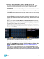
Patching Moving Lights, LEDs, and Accessories . . . . . . . . . . . . . . .75
Display Pages in Patch . . . . . . . . . . . . . . . . . . . . . . . . . . . . . . . . . .76
{Patch} Display and Settings . . . . . . . . . . . . . . . . . . . . . . . . . . .76
{Attribute} Display and Settings . . . . . . . . . . . . . . . . . . . . . . . . .78
3
{Database} Display and Settings . . . . . . . . . . . . . . . . . . . . . . . .80
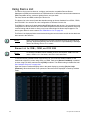
Using Device List . . . . . . . . . . . . . . . . . . . . . . . . . . . . . . . . . . . . . . .82
Dimmer List for CEM+, CEM3, and FDX 2000 . . . . . . . . . . . . .82
RDM Device List . . . . . . . . . . . . . . . . . . . . . . . . . . . . . . . . . . . .84
Patching Discovered Dimmers and RDM Devices . . . . . . . . . .86
Errors and Warnings . . . . . . . . . . . . . . . . . . . . . . . . . . . . . . . . .86
Detaching Devices. . . . . . . . . . . . . . . . . . . . . . . . . . . . . . . . . . .87
Clearing the Patch . . . . . . . . . . . . . . . . . . . . . . . . . . . . . . . . . . . . . .87
Reset Patch . . . . . . . . . . . . . . . . . . . . . . . . . . . . . . . . . . . . . . . .87
Fixture Creator . . . . . . . . . . . . . . . . . . . . . . . . . . . . . . . . . . . . . . . . .88
Creating a New Fixture . . . . . . . . . . . . . . . . . . . . . . . . . . . . . . .88
Copying a Fixture. . . . . . . . . . . . . . . . . . . . . . . . . . . . . . . . . . . .92
Merging Custom Fixtures into a New Show File . . . . . . . . . . . .92
Importing a Custom Fixture . . . . . . . . . . . . . . . . . . . . . . . . . . . .92
Update Library . . . . . . . . . . . . . . . . . . . . . . . . . . . . . . . . . . . . . .92
Snap Parameters. . . . . . . . . . . . . . . . . . . . . . . . . . . . . . . . . . . .93
Chapter 5
Setup . . . . . . . . . . . . . . . . . . . . . . . . . . . . . 95
Opening Setup . . . . . . . . . . . . . . . . . . . . . . . . . . . . . . . . . . . . . . . . .96
Show . . . . . . . . . . . . . . . . . . . . . . . . . . . . . . . . . . . . . . . . . . . . .96
Desk. . . . . . . . . . . . . . . . . . . . . . . . . . . . . . . . . . . . . . . . . . . . .103
Chapter 6
Basic Manual Control . . . . . . . . . . . . . . . . 111
Selecting Channels . . . . . . . . . . . . . . . . . . . . . . . . . . . . . . . . . . . .112
Select Channels From the Keypad . . . . . . . . . . . . . . . . . . . . .112
Selecting Channels from Faders . . . . . . . . . . . . . . . . . . . . . . .112
Using Groups as a Channel Collector . . . . . . . . . . . . . . . . . . .112
Offset . . . . . . . . . . . . . . . . . . . . . . . . . . . . . . . . . . . . . . . . . . . .113
Setting Intensity . . . . . . . . . . . . . . . . . . . . . . . . . . . . . . . . . . . . . . .114
Level Wheel . . . . . . . . . . . . . . . . . . . . . . . . . . . . . . . . . . . . . . .114
Manual Control of Non-intensity Parameters (NPs) . . . . . . . . . . . .115
Parameter Display . . . . . . . . . . . . . . . . . . . . . . . . . . . . . . . . . .115
Setting Parameters with the Keypad . . . . . . . . . . . . . . . . . . . .116
Adjusting Parameters Using + and - . . . . . . . . . . . . . . . . . . . .116
Setting Non-intensity Parameters with the Encoders . . . . . . .116
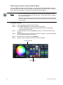
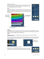
Using the Color Picker . . . . . . . . . . . . . . . . . . . . . . . . . . . . . . .121
Home . . . . . . . . . . . . . . . . . . . . . . . . . . . . . . . . . . . . . . . . . . . . . . .123
Select Last . . . . . . . . . . . . . . . . . . . . . . . . . . . . . . . . . . . . . . . . . . .123
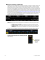
Multiple Intensity Channels . . . . . . . . . . . . . . . . . . . . . . . . . . . . . .124
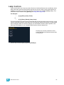
Lamp Controls . . . . . . . . . . . . . . . . . . . . . . . . . . . . . . . . . . . . . . . .125
Using +% and -% . . . . . . . . . . . . . . . . . . . . . . . . . . . . . . . . . . . . . .126
Channel Intensity . . . . . . . . . . . . . . . . . . . . . . . . . . . . . . . . . . .126
Non-intensity Parameters . . . . . . . . . . . . . . . . . . . . . . . . . . . .126
Remainder Dim . . . . . . . . . . . . . . . . . . . . . . . . . . . . . . . . . . . . . . .127
Highlight and Lowlight . . . . . . . . . . . . . . . . . . . . . . . . . . . . . . . . . .128
4
Ion Operations Manual
Lowlight Preset . . . . . . . . . . . . . . . . . . . . . . . . . . . . . . . . . . . .128
Temporary Highlight Level. . . . . . . . . . . . . . . . . . . . . . . . . . . .129
Highlight/Lowlight Rem Dim. . . . . . . . . . . . . . . . . . . . . . . . . . .129
Sneak . . . . . . . . . . . . . . . . . . . . . . . . . . . . . . . . . . . . . . . . . . . . . . .130
Flip . . . . . . . . . . . . . . . . . . . . . . . . . . . . . . . . . . . . . . . . . . . . . . . . .131
Channel Check . . . . . . . . . . . . . . . . . . . . . . . . . . . . . . . . . . . . . . . .131
Address at Level. . . . . . . . . . . . . . . . . . . . . . . . . . . . . . . . . . . . . . .131
Address Check . . . . . . . . . . . . . . . . . . . . . . . . . . . . . . . . . . . . . . . .131
Flash. . . . . . . . . . . . . . . . . . . . . . . . . . . . . . . . . . . . . . . . . . . . . . . .132
Flash On & Flash Off . . . . . . . . . . . . . . . . . . . . . . . . . . . . . . . .132
Using {Move To}. . . . . . . . . . . . . . . . . . . . . . . . . . . . . . . . . . . . . . .132
Chapter 7
Using Groups . . . . . . . . . . . . . . . . . . . . . . 133
Recording Groups Live. . . . . . . . . . . . . . . . . . . . . . . . . . . . . . . . . .134
Ordered Channels . . . . . . . . . . . . . . . . . . . . . . . . . . . . . . . . . .134
Offset . . . . . . . . . . . . . . . . . . . . . . . . . . . . . . . . . . . . . . . . . . . .135
Editing and Updating Groups in Live . . . . . . . . . . . . . . . . . . . .135
Selecting Groups . . . . . . . . . . . . . . . . . . . . . . . . . . . . . . . . . . . . . .135
Deleting Groups. . . . . . . . . . . . . . . . . . . . . . . . . . . . . . . . . . . .135
Group List. . . . . . . . . . . . . . . . . . . . . . . . . . . . . . . . . . . . . . . . . . . .136
Open the Group List . . . . . . . . . . . . . . . . . . . . . . . . . . . . . . . .136
Ordered View and Numeric View. . . . . . . . . . . . . . . . . . . . . . .136
Editing Groups from the Group List . . . . . . . . . . . . . . . . . . . . .136
Using Groups as a Channel Collector . . . . . . . . . . . . . . . . . . .137
Chapter 8
Storing and Using Palettes . . . . . . . . . . . . 139
About Palettes . . . . . . . . . . . . . . . . . . . . . . . . . . . . . . . . . . . . . . . .140
Palette Types . . . . . . . . . . . . . . . . . . . . . . . . . . . . . . . . . . . . . . . . .140
Intensity Palettes . . . . . . . . . . . . . . . . . . . . . . . . . . . . . . . . . . .140
Focus Palettes . . . . . . . . . . . . . . . . . . . . . . . . . . . . . . . . . . . . .140
Color Palettes . . . . . . . . . . . . . . . . . . . . . . . . . . . . . . . . . . . . .140
Beam Palettes . . . . . . . . . . . . . . . . . . . . . . . . . . . . . . . . . . . . .140
Palette Options . . . . . . . . . . . . . . . . . . . . . . . . . . . . . . . . . . . . . . . .140
{By Type} . . . . . . . . . . . . . . . . . . . . . . . . . . . . . . . . . . . . . . . . .140
{Absolute} . . . . . . . . . . . . . . . . . . . . . . . . . . . . . . . . . . . . . . . .140
{Locked}. . . . . . . . . . . . . . . . . . . . . . . . . . . . . . . . . . . . . . . . . .141
Storing Palettes Live . . . . . . . . . . . . . . . . . . . . . . . . . . . . . . . . . . .142
Storing Palettes with [Record] . . . . . . . . . . . . . . . . . . . . . . . . .142
Storing Palettes with [Record Only] . . . . . . . . . . . . . . . . . . . . .143
Using Filters with Palettes . . . . . . . . . . . . . . . . . . . . . . . . . . . .144
Recalling Palettes. . . . . . . . . . . . . . . . . . . . . . . . . . . . . . . . . . . . . .145
Editing Palettes Live . . . . . . . . . . . . . . . . . . . . . . . . . . . . . . . . . . . .146
Rerecord . . . . . . . . . . . . . . . . . . . . . . . . . . . . . . . . . . . . . . . . .146
5
Update . . . . . . . . . . . . . . . . . . . . . . . . . . . . . . . . . . . . . . . . . . .146
Editing Palettes in Blind . . . . . . . . . . . . . . . . . . . . . . . . . . . . . . . . .147
Entering Blind Palette from Live . . . . . . . . . . . . . . . . . . . . . . .147
Editing in Blind . . . . . . . . . . . . . . . . . . . . . . . . . . . . . . . . . . . . .147
Editing Palettes in Spreadsheet View . . . . . . . . . . . . . . . . . . .148
Editing Palettes in List View. . . . . . . . . . . . . . . . . . . . . . . . . . .148
Deleting Palettes . . . . . . . . . . . . . . . . . . . . . . . . . . . . . . . . . . .149
Removing Channels from a Palette . . . . . . . . . . . . . . . . . . . . .149
Using By Type Palettes . . . . . . . . . . . . . . . . . . . . . . . . . . . . . . . . .150
Storing a By Type Palette . . . . . . . . . . . . . . . . . . . . . . . . . . . .150
Editing By Type Palettes in Blind. . . . . . . . . . . . . . . . . . . . . . .150
Updating By Type Palettes . . . . . . . . . . . . . . . . . . . . . . . . . . .150
Chapter 9
Storing and Using Presets . . . . . . . . . . . . 151
Storing Presets Live . . . . . . . . . . . . . . . . . . . . . . . . . . . . . . . . . . . .152
Storing Presets Using [Record] . . . . . . . . . . . . . . . . . . . . . . . .152
Storing Presets using [Record Only] . . . . . . . . . . . . . . . . . . . .153
Preset Options . . . . . . . . . . . . . . . . . . . . . . . . . . . . . . . . . . . . .153
Recalling Presets . . . . . . . . . . . . . . . . . . . . . . . . . . . . . . . . . . . . . .154
Editing Presets Live . . . . . . . . . . . . . . . . . . . . . . . . . . . . . . . . . . . .155
Rerecord . . . . . . . . . . . . . . . . . . . . . . . . . . . . . . . . . . . . . . . . .155
Update . . . . . . . . . . . . . . . . . . . . . . . . . . . . . . . . . . . . . . . . . . .155
Using the Preset List . . . . . . . . . . . . . . . . . . . . . . . . . . . . . . . . . . .156
Opening the Preset List . . . . . . . . . . . . . . . . . . . . . . . . . . . . . .156
Editing Presets in Blind . . . . . . . . . . . . . . . . . . . . . . . . . . . . . . . . .157
Editing in Table View . . . . . . . . . . . . . . . . . . . . . . . . . . . . . . . .157
Editing in Spreadsheet View . . . . . . . . . . . . . . . . . . . . . . . . . .158
Deleting Presets . . . . . . . . . . . . . . . . . . . . . . . . . . . . . . . . . . .158
Removing Channels from a Preset . . . . . . . . . . . . . . . . . . . . .158
Chapter 10
Using Fan . . . . . . . . . . . . . . . . . . . . . . . . . 159
About Fan . . . . . . . . . . . . . . . . . . . . . . . . . . . . . . . . . . . . . . . . . . . .160
Fanning Parameter Data . . . . . . . . . . . . . . . . . . . . . . . . . . . . .160
Fan From the Command Line . . . . . . . . . . . . . . . . . . . . . . . . .160
Fanning References . . . . . . . . . . . . . . . . . . . . . . . . . . . . . . . .161
Fanning Timing and Delays . . . . . . . . . . . . . . . . . . . . . . . . . . .161
Chapter 11
Working with a Single Cue List . . . . . . . . . 163
Basic Cueing . . . . . . . . . . . . . . . . . . . . . . . . . . . . . . . . . . . . . . . . .164
Cue Numbering . . . . . . . . . . . . . . . . . . . . . . . . . . . . . . . . . . . .164
Recording Cues in Live . . . . . . . . . . . . . . . . . . . . . . . . . . . . . . . . .165
Using Record . . . . . . . . . . . . . . . . . . . . . . . . . . . . . . . . . . . . . .165
Using Record Only. . . . . . . . . . . . . . . . . . . . . . . . . . . . . . . . . .166
Using Selective Store . . . . . . . . . . . . . . . . . . . . . . . . . . . . . . .167
6
Ion Operations Manual
Using [Cue Only / Track] . . . . . . . . . . . . . . . . . . . . . . . . . . . . .168
Timing. . . . . . . . . . . . . . . . . . . . . . . . . . . . . . . . . . . . . . . . . . . . . . .169
Setting Cue Level Timing. . . . . . . . . . . . . . . . . . . . . . . . . . . . .169
Non-intensity Parameter Category Timing. . . . . . . . . . . . . . . .170
Delay Time. . . . . . . . . . . . . . . . . . . . . . . . . . . . . . . . . . . . . . . .171
[Time][/] . . . . . . . . . . . . . . . . . . . . . . . . . . . . . . . . . . . . . . . . . .171
Discrete Channel or Parameter Timing . . . . . . . . . . . . . . . . . .172
Assigning Cue Attributes . . . . . . . . . . . . . . . . . . . . . . . . . . . . .173
Clearing Cue Attributes . . . . . . . . . . . . . . . . . . . . . . . . . . . . . .175
Flags. . . . . . . . . . . . . . . . . . . . . . . . . . . . . . . . . . . . . . . . . . . . . . . .176
Block . . . . . . . . . . . . . . . . . . . . . . . . . . . . . . . . . . . . . . . . . . . .176
Assert. . . . . . . . . . . . . . . . . . . . . . . . . . . . . . . . . . . . . . . . . . . .177
AllFade. . . . . . . . . . . . . . . . . . . . . . . . . . . . . . . . . . . . . . . . . . .177
Mark. . . . . . . . . . . . . . . . . . . . . . . . . . . . . . . . . . . . . . . . . . . . .177
Preheat . . . . . . . . . . . . . . . . . . . . . . . . . . . . . . . . . . . . . . . . . .177
Using External Links . . . . . . . . . . . . . . . . . . . . . . . . . . . . . . . .178
Modifying Cues Live . . . . . . . . . . . . . . . . . . . . . . . . . . . . . . . . . . . .179
Using [At] [Enter] . . . . . . . . . . . . . . . . . . . . . . . . . . . . . . . . . . .179
Using Record . . . . . . . . . . . . . . . . . . . . . . . . . . . . . . . . . . . . . .179
Using Record Only. . . . . . . . . . . . . . . . . . . . . . . . . . . . . . . . . .180
Record and Record Only [+] . . . . . . . . . . . . . . . . . . . . . . . . . .180
Move To. . . . . . . . . . . . . . . . . . . . . . . . . . . . . . . . . . . . . . . . . .180
[Update] . . . . . . . . . . . . . . . . . . . . . . . . . . . . . . . . . . . . . . . . . .181
Recording and Editing Cues from Blind . . . . . . . . . . . . . . . . . . . . .186
From Summary or Table Views . . . . . . . . . . . . . . . . . . . . . . . .187
From the Cue Spreadsheet . . . . . . . . . . . . . . . . . . . . . . . . . . .187
Using Encoders in Blind. . . . . . . . . . . . . . . . . . . . . . . . . . . . . .188
Deleting Cues . . . . . . . . . . . . . . . . . . . . . . . . . . . . . . . . . . . . . . . . .189
In Track Mode . . . . . . . . . . . . . . . . . . . . . . . . . . . . . . . . . . . . .189
In Cue Only Mode . . . . . . . . . . . . . . . . . . . . . . . . . . . . . . . . . .189
Chapter 12
Using Mark . . . . . . . . . . . . . . . . . . . . . . . . 191
AutoMark . . . . . . . . . . . . . . . . . . . . . . . . . . . . . . . . . . . . . . . . . . . .192
Conditions Triggering an AutoMark . . . . . . . . . . . . . . . . . . . . .192
Allowing a Live Move . . . . . . . . . . . . . . . . . . . . . . . . . . . . . . . .192
AutoMark and Timing. . . . . . . . . . . . . . . . . . . . . . . . . . . . . . . .192
Referenced Marks . . . . . . . . . . . . . . . . . . . . . . . . . . . . . . . . . . . . .193
Setting Referenced Mark Flags . . . . . . . . . . . . . . . . . . . . . . . .193
Applying Flags as Channels are Marked . . . . . . . . . . . . . . . . .194
Reference Marks and Timing. . . . . . . . . . . . . . . . . . . . . . . . . .197
Mark Time . . . . . . . . . . . . . . . . . . . . . . . . . . . . . . . . . . . . . . . .197
Chapter 13
Using Filters . . . . . . . . . . . . . . . . . . . . . . . 199
Record Filters . . . . . . . . . . . . . . . . . . . . . . . . . . . . . . . . . . . . . . . . .200
Partial Filters . . . . . . . . . . . . . . . . . . . . . . . . . . . . . . . . . . . . . .201
Removing Filters . . . . . . . . . . . . . . . . . . . . . . . . . . . . . . . . . . .201
Storing Data with Record Filters . . . . . . . . . . . . . . . . . . . . . . .201
7
Chapter 14
Working with Multiple Cue Lists . . . . . . . . 203
Recording to a New Cue List . . . . . . . . . . . . . . . . . . . . . . . . . . . . .204
Using Record . . . . . . . . . . . . . . . . . . . . . . . . . . . . . . . . . . . . . .204
Using Record Only. . . . . . . . . . . . . . . . . . . . . . . . . . . . . . . . . .204
Using Assert . . . . . . . . . . . . . . . . . . . . . . . . . . . . . . . . . . . . . .204
Using AllFade . . . . . . . . . . . . . . . . . . . . . . . . . . . . . . . . . . . . .206
Changing the Active Cue List . . . . . . . . . . . . . . . . . . . . . . . . .206
Using [Go To Cue] with Multiple Cue Lists . . . . . . . . . . . . . . . . . . .207
Using Go To Cue 0 . . . . . . . . . . . . . . . . . . . . . . . . . . . . . . . . .207
Using Go To Cue Out . . . . . . . . . . . . . . . . . . . . . . . . . . . . . . .207
Using the Cue List Index . . . . . . . . . . . . . . . . . . . . . . . . . . . . . . . .208
Open the Cue List Index . . . . . . . . . . . . . . . . . . . . . . . . . . . . .208
Chapter 15
Multipart Cues. . . . . . . . . . . . . . . . . . . . . . 211
About Multipart Cues . . . . . . . . . . . . . . . . . . . . . . . . . . . . . . . . . . .212
Record a Multipart Cue in Live . . . . . . . . . . . . . . . . . . . . . . . . . . . .212
Creating a New Multipart Cue in Live . . . . . . . . . . . . . . . . . . .212
Setting Multipart Cue Attributes . . . . . . . . . . . . . . . . . . . . . . . .213
Using Update in Live . . . . . . . . . . . . . . . . . . . . . . . . . . . . . . . .213
Storing a Multipart Cue in Blind . . . . . . . . . . . . . . . . . . . . . . . . . . .214
Changing a Single Part Cue to a Multipart Cue. . . . . . . . . . . .214
Changing a Multipart Cue to a Standard Cue . . . . . . . . . . . . .214
Deleting a Part from a Multipart Cue . . . . . . . . . . . . . . . . . . . .214
Chapter 16
Cue Playback . . . . . . . . . . . . . . . . . . . . . . 215
Introduction to Playback . . . . . . . . . . . . . . . . . . . . . . . . . . . . . . . . .216
Playback Controls . . . . . . . . . . . . . . . . . . . . . . . . . . . . . . . . . .216
Selected Cue . . . . . . . . . . . . . . . . . . . . . . . . . . . . . . . . . . . . . . . . .217
Live / Blind . . . . . . . . . . . . . . . . . . . . . . . . . . . . . . . . . . . . . . . .217
Out-of-Sequence Cues. . . . . . . . . . . . . . . . . . . . . . . . . . . . . . . . . .218
Go To Cue . . . . . . . . . . . . . . . . . . . . . . . . . . . . . . . . . . . . . . . .218
Slider Module . . . . . . . . . . . . . . . . . . . . . . . . . . . . . . . . . . . . . . . . .220
Assigning Faders . . . . . . . . . . . . . . . . . . . . . . . . . . . . . . . . . . .220
Changing Fader Pages . . . . . . . . . . . . . . . . . . . . . . . . . . . . . .220
Playback Fader Controls . . . . . . . . . . . . . . . . . . . . . . . . . . . . . . . .221
Go and Stop/Back . . . . . . . . . . . . . . . . . . . . . . . . . . . . . . . . . .221
Using Blackout. . . . . . . . . . . . . . . . . . . . . . . . . . . . . . . . . . . . .221
[Go To Cue] [0] . . . . . . . . . . . . . . . . . . . . . . . . . . . . . . . . . . . .221
Using Assert (Playback Button) . . . . . . . . . . . . . . . . . . . . . . . .224
Using Timing Disable. . . . . . . . . . . . . . . . . . . . . . . . . . . . . . . .224
Using Freeze . . . . . . . . . . . . . . . . . . . . . . . . . . . . . . . . . . . . . .224
Using Stop Effect . . . . . . . . . . . . . . . . . . . . . . . . . . . . . . . . . . .225
Releasing Content From a Fader . . . . . . . . . . . . . . . . . . . . . .225
Using Rate Override . . . . . . . . . . . . . . . . . . . . . . . . . . . . . . . .225
Manual Master Cue Lists . . . . . . . . . . . . . . . . . . . . . . . . . . . . . . . .226
8
Ion Operations Manual
Chapter 17
Advanced Manual Control. . . . . . . . . . . . . 227
Using [Copy To] . . . . . . . . . . . . . . . . . . . . . . . . . . . . . . . . . . . . . . .228
Using [Recall From] . . . . . . . . . . . . . . . . . . . . . . . . . . . . . . . . . . . .229
Using {Make Null}. . . . . . . . . . . . . . . . . . . . . . . . . . . . . . . . . . . . . .230
In Live . . . . . . . . . . . . . . . . . . . . . . . . . . . . . . . . . . . . . . . . . . .230
In Blind. . . . . . . . . . . . . . . . . . . . . . . . . . . . . . . . . . . . . . . . . . .230
Using {Make Manual} . . . . . . . . . . . . . . . . . . . . . . . . . . . . . . . . . . .231
Using {Make Absolute} . . . . . . . . . . . . . . . . . . . . . . . . . . . . . . . . . .231
Using {Query} . . . . . . . . . . . . . . . . . . . . . . . . . . . . . . . . . . . . . . . . .232
Using [Capture] . . . . . . . . . . . . . . . . . . . . . . . . . . . . . . . . . . . . . . .233
Using [Undo]. . . . . . . . . . . . . . . . . . . . . . . . . . . . . . . . . . . . . . . . . .234
Command History . . . . . . . . . . . . . . . . . . . . . . . . . . . . . . . . . .234
Chapter 18
Using Park . . . . . . . . . . . . . . . . . . . . . . . . 235
Using Park . . . . . . . . . . . . . . . . . . . . . . . . . . . . . . . . . . . . . . . . . . .236
Park Display. . . . . . . . . . . . . . . . . . . . . . . . . . . . . . . . . . . . . . .236
Parked Values in Live . . . . . . . . . . . . . . . . . . . . . . . . . . . . . . .236
Scaled Parked Values in Live . . . . . . . . . . . . . . . . . . . . . . . . .237
Parked Addresses in Live . . . . . . . . . . . . . . . . . . . . . . . . . . . .237
Park Values from the Park Display . . . . . . . . . . . . . . . . . . . . .238
Chapter 19
Creating and Using Effects . . . . . . . . . . . . 239
About Effects . . . . . . . . . . . . . . . . . . . . . . . . . . . . . . . . . . . . . . . . .240
The Effect List . . . . . . . . . . . . . . . . . . . . . . . . . . . . . . . . . . . . .240
Effects Editor . . . . . . . . . . . . . . . . . . . . . . . . . . . . . . . . . . . . . .241
Effect Status Display . . . . . . . . . . . . . . . . . . . . . . . . . . . . . . . .244
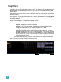
Step Effects . . . . . . . . . . . . . . . . . . . . . . . . . . . . . . . . . . . . . . . . . .245
Program a Step Effect . . . . . . . . . . . . . . . . . . . . . . . . . . . . . . .246
Absolute Effects . . . . . . . . . . . . . . . . . . . . . . . . . . . . . . . . . . . . . . .248
Program an Absolute Effect. . . . . . . . . . . . . . . . . . . . . . . . . . .249
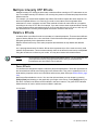
Multiple Intensity HTP Effects . . . . . . . . . . . . . . . . . . . . . . . . . . . .250
Relative Effects . . . . . . . . . . . . . . . . . . . . . . . . . . . . . . . . . . . . . . .250
Focus Effects . . . . . . . . . . . . . . . . . . . . . . . . . . . . . . . . . . . . . .250
Color Effects . . . . . . . . . . . . . . . . . . . . . . . . . . . . . . . . . . . . . .251
Linear Effects. . . . . . . . . . . . . . . . . . . . . . . . . . . . . . . . . . . . . .251
Define a Pattern Shape . . . . . . . . . . . . . . . . . . . . . . . . . . . . . .252
Program a New Relative Effect . . . . . . . . . . . . . . . . . . . . . . . .252
Apply an Existing Effect . . . . . . . . . . . . . . . . . . . . . . . . . . . . . . . . .253
Recording an Effect in a Cue. . . . . . . . . . . . . . . . . . . . . . . . . .253
Editing Effects Live . . . . . . . . . . . . . . . . . . . . . . . . . . . . . . . . .253
Stop an Effect . . . . . . . . . . . . . . . . . . . . . . . . . . . . . . . . . . . . .253
Deleting an Effect . . . . . . . . . . . . . . . . . . . . . . . . . . . . . . . . . .253
Effects on Submasters . . . . . . . . . . . . . . . . . . . . . . . . . . . . . . . . . .254
9
Configuring an Effect Submaster. . . . . . . . . . . . . . . . . . . . . . .254
Recording an Effect to a Submaster . . . . . . . . . . . . . . . . . . . .254
Running an Effect from a Submaster. . . . . . . . . . . . . . . . . . . .254
Delaying Effects . . . . . . . . . . . . . . . . . . . . . . . . . . . . . . . . . . . . . . .255
Chapter 20
Storing and Using Submasters . . . . . . . . . 257
About Submasters . . . . . . . . . . . . . . . . . . . . . . . . . . . . . . . . . . . . .258
Recording a Submaster . . . . . . . . . . . . . . . . . . . . . . . . . . . . . .258
Submaster Displays. . . . . . . . . . . . . . . . . . . . . . . . . . . . . . . . .259
Additive, Inhibitive, or Effectsub. . . . . . . . . . . . . . . . . . . . . . . .259
Proportional vs. Intensity Master . . . . . . . . . . . . . . . . . . . . . . .259
HTP vs. LTP . . . . . . . . . . . . . . . . . . . . . . . . . . . . . . . . . . . . . .260
Exclusive Submasters . . . . . . . . . . . . . . . . . . . . . . . . . . . . . . .260
Priority . . . . . . . . . . . . . . . . . . . . . . . . . . . . . . . . . . . . . . . . . . .260
Restore . . . . . . . . . . . . . . . . . . . . . . . . . . . . . . . . . . . . . . . . . .261
Submaster Background State . . . . . . . . . . . . . . . . . . . . . . . . .261
Changing Fader Pages . . . . . . . . . . . . . . . . . . . . . . . . . . . . . . . . .262
On Fader Wings. . . . . . . . . . . . . . . . . . . . . . . . . . . . . . . . . . . .262
On the Slider Module . . . . . . . . . . . . . . . . . . . . . . . . . . . . . . . .262
Loading Submasters . . . . . . . . . . . . . . . . . . . . . . . . . . . . . . . . . . .263
On Fader Wings. . . . . . . . . . . . . . . . . . . . . . . . . . . . . . . . . . . .263
On the Slider Module . . . . . . . . . . . . . . . . . . . . . . . . . . . . . . . .263
Updating a Submaster . . . . . . . . . . . . . . . . . . . . . . . . . . . . . . .264
Releasing Content From a Submaster . . . . . . . . . . . . . . . . . .264
Deleting a Submaster . . . . . . . . . . . . . . . . . . . . . . . . . . . . . . .264
Using Bump Button Timing With Submasters . . . . . . . . . . . . . . . .265
Controlling Subfades Manually . . . . . . . . . . . . . . . . . . . . . . . .265
Submaster List . . . . . . . . . . . . . . . . . . . . . . . . . . . . . . . . . . . . . . . .266
Editing Submasters . . . . . . . . . . . . . . . . . . . . . . . . . . . . . . . . .266
Chapter 21
Using About . . . . . . . . . . . . . . . . . . . . . . . 267
About [About] . . . . . . . . . . . . . . . . . . . . . . . . . . . . . . . . . . . . . . . . .268
[About] . . . . . . . . . . . . . . . . . . . . . . . . . . . . . . . . . . . . . . . . . . .269
About System . . . . . . . . . . . . . . . . . . . . . . . . . . . . . . . . . . . . .269
About Channel . . . . . . . . . . . . . . . . . . . . . . . . . . . . . . . . . . . . .270
About Address . . . . . . . . . . . . . . . . . . . . . . . . . . . . . . . . . . . . .272
About Cue . . . . . . . . . . . . . . . . . . . . . . . . . . . . . . . . . . . . . . . .275
About IFCB Palettes . . . . . . . . . . . . . . . . . . . . . . . . . . . . . . . .275
About Presets . . . . . . . . . . . . . . . . . . . . . . . . . . . . . . . . . . . . .275
About Groups. . . . . . . . . . . . . . . . . . . . . . . . . . . . . . . . . . . . . .275
About Curves . . . . . . . . . . . . . . . . . . . . . . . . . . . . . . . . . . . . . .276
About Effects . . . . . . . . . . . . . . . . . . . . . . . . . . . . . . . . . . . . . .276
Chapter 22
Storing and Using Curves . . . . . . . . . . . . . 277
About Curves . . . . . . . . . . . . . . . . . . . . . . . . . . . . . . . . . . . . . . . . .278
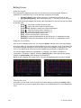
Creating and Editing Curves . . . . . . . . . . . . . . . . . . . . . . . . . . . . .279
10
Ion Operations Manual
Creating a Curve . . . . . . . . . . . . . . . . . . . . . . . . . . . . . . . . . . .279
Editing Curves . . . . . . . . . . . . . . . . . . . . . . . . . . . . . . . . . . . . .280
Applying a Curve . . . . . . . . . . . . . . . . . . . . . . . . . . . . . . . . . . . . . .281
To Channels In Patch . . . . . . . . . . . . . . . . . . . . . . . . . . . . . . .281
To Cues . . . . . . . . . . . . . . . . . . . . . . . . . . . . . . . . . . . . . . . . . .281
To Scroller Fans . . . . . . . . . . . . . . . . . . . . . . . . . . . . . . . . . . .281
Delete a Curve . . . . . . . . . . . . . . . . . . . . . . . . . . . . . . . . . . . . . . . .281
Chapter 23
Storing and Using Snapshots . . . . . . . . . . 283
About Snapshots . . . . . . . . . . . . . . . . . . . . . . . . . . . . . . . . . . . . . .284
Recording Snapshots . . . . . . . . . . . . . . . . . . . . . . . . . . . . . . . . . . .284
Recalling Snapshots. . . . . . . . . . . . . . . . . . . . . . . . . . . . . . . . . . . .285
Editing Snapshots . . . . . . . . . . . . . . . . . . . . . . . . . . . . . . . . . . . . .285
Deleting Snapshots . . . . . . . . . . . . . . . . . . . . . . . . . . . . . . . . .285
Chapter 24
Storing and Using Macros. . . . . . . . . . . . . 287
About Macros . . . . . . . . . . . . . . . . . . . . . . . . . . . . . . . . . . . . . . . . .288
Store a Macro from Live . . . . . . . . . . . . . . . . . . . . . . . . . . . . . . . . .288
Using the [Learn] key. . . . . . . . . . . . . . . . . . . . . . . . . . . . . . . .288
Macro Editor Display . . . . . . . . . . . . . . . . . . . . . . . . . . . . . . . . . . .290
Create a New Macro from the Display. . . . . . . . . . . . . . . . . . .292
Edit an Existing Macro . . . . . . . . . . . . . . . . . . . . . . . . . . . . . . .293
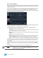
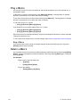
Play a Macro . . . . . . . . . . . . . . . . . . . . . . . . . . . . . . . . . . . . . . . . .294
Stop a Macro . . . . . . . . . . . . . . . . . . . . . . . . . . . . . . . . . . . . . .294
Delete a Macro . . . . . . . . . . . . . . . . . . . . . . . . . . . . . . . . . . . . . . . .294
Chapter 25
Using Magic Sheets . . . . . . . . . . . . . . . . . 295
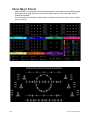
About Magic Sheets . . . . . . . . . . . . . . . . . . . . . . . . . . . . . . . . . . . .296
Magic Sheet Display. . . . . . . . . . . . . . . . . . . . . . . . . . . . . . . . . . . .297
Magic Sheet List . . . . . . . . . . . . . . . . . . . . . . . . . . . . . . . . . . .298
Display Tools . . . . . . . . . . . . . . . . . . . . . . . . . . . . . . . . . . . . . .298
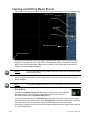
Navigating a Magic Sheet . . . . . . . . . . . . . . . . . . . . . . . . . . . . . . .299
Creating and Editing Magic Sheets . . . . . . . . . . . . . . . . . . . . . . . .300
Quick Save . . . . . . . . . . . . . . . . . . . . . . . . . . . . . . . . . . . . . . .300
Layout Tools . . . . . . . . . . . . . . . . . . . . . . . . . . . . . . . . . . . . . .301
Magic Sheet Object Library . . . . . . . . . . . . . . . . . . . . . . . . . . .303
MS Object Properties. . . . . . . . . . . . . . . . . . . . . . . . . . . . . . . .307
Editing Objects on the Magic Sheet. . . . . . . . . . . . . . . . . . . . .308
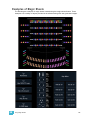
Examples of Magic Sheets . . . . . . . . . . . . . . . . . . . . . . . . . . . . . . .309
11
Chapter 26
Virtual Media Server . . . . . . . . . . . . . . . . . 311
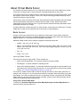
About Virtual Media Server . . . . . . . . . . . . . . . . . . . . . . . . . . . . . .312
Media Content . . . . . . . . . . . . . . . . . . . . . . . . . . . . . . . . . . . . .312
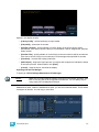
Patching the Virtual Media Server and Layers . . . . . . . . . . . .314
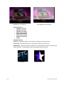
Creating a Pixel Map . . . . . . . . . . . . . . . . . . . . . . . . . . . . . . . .315
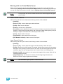
Working with the Virtual Media Server. . . . . . . . . . . . . . . . . . .317
Effect Layers . . . . . . . . . . . . . . . . . . . . . . . . . . . . . . . . . . . . . .322
Pixel Mapping in a Multi-Console System . . . . . . . . . . . . . . . . . . .324
Steps for Configuring a Multi-Console System . . . . . . . . . . . .324
Synchronizing Media Archives. . . . . . . . . . . . . . . . . . . . . . . . .325
Chapter 27
Multiple Users . . . . . . . . . . . . . . . . . . . . . . 327
About User ID . . . . . . . . . . . . . . . . . . . . . . . . . . . . . . . . . . . . . . . . .328
Assigning User ID . . . . . . . . . . . . . . . . . . . . . . . . . . . . . . . . . .328
Chapter 28
Using Partitioned Control . . . . . . . . . . . . . 329
About Partitioned Control . . . . . . . . . . . . . . . . . . . . . . . . . . . . . . . .330
How to Use Partitions . . . . . . . . . . . . . . . . . . . . . . . . . . . . . . .330
Setting Up Partitioned Control . . . . . . . . . . . . . . . . . . . . . . . . .330
Partition List . . . . . . . . . . . . . . . . . . . . . . . . . . . . . . . . . . . . . . .330
Creating New Partitions . . . . . . . . . . . . . . . . . . . . . . . . . . . . . .331
Deleting Partitions . . . . . . . . . . . . . . . . . . . . . . . . . . . . . . . . . .331
Using Partitions . . . . . . . . . . . . . . . . . . . . . . . . . . . . . . . . . . . . . . .332
Partitions in Playback . . . . . . . . . . . . . . . . . . . . . . . . . . . . . . .332
Flexichannel in Partitioned Control . . . . . . . . . . . . . . . . . . . . .332
Appendix A
Eos Configuration Utility . . . . . . . . . . . . . . 333
Overview . . . . . . . . . . . . . . . . . . . . . . . . . . . . . . . . . . . . . . . . . . . 333
What the Utility Does . . . . . . . . . . . . . . . . . . . . . . . . . . . . . . . . . . 333
Eos Configuration Utility Reference . . . . . . . . . . . . . . . . . . . . . . . 334
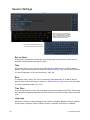
General Settings. . . . . . . . . . . . . . . . . . . . . . . . . . . . . . . . . . . . . . 336
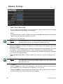
Network Settings . . . . . . . . . . . . . . . . . . . . . . . . . . . . . . . . . . . . . 340
Maintenance and Diagnostics . . . . . . . . . . . . . . . . . . . . . . . . . . . 346
Buttons . . . . . . . . . . . . . . . . . . . . . . . . . . . . . . . . . . . . . . . . . . . . . 351
Local I/O . . . . . . . . . . . . . . . . . . . . . . . . . . . . . . . . . . . . . . . . . . . . 351
RFR . . . . . . . . . . . . . . . . . . . . . . . . . . . . . . . . . . . . . . . . . . . . . . . 352
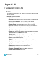
Appendix B
Facepanel Shortcuts . . . . . . . . . . . . . . . . . 353
Overview . . . . . . . . . . . . . . . . . . . . . . . . . . . . . . . . . . . . . . . . . . . 353
Facepanel and Displays . . . . . . . . . . . . . . . . . . . . . . . . . . . . . . . . 353
12
Ion Operations Manual
Operations . . . . . . . . . . . . . . . . . . . . . . . . . . . . . . . . . . . . . . . . . . 354
Appendix C
Multi-console and Synchronized Backup . 357
Overview . . . . . . . . . . . . . . . . . . . . . . . . . . . . . . . . . . . . . . . . . . . 357
Multi-console setup . . . . . . . . . . . . . . . . . . . . . . . . . . . . . . . . . . . 358
Synchronized Backup. . . . . . . . . . . . . . . . . . . . . . . . . . . . . . . . . . 361
Mirror Mode . . . . . . . . . . . . . . . . . . . . . . . . . . . . . . . . . . . . . . . . . 365
Appendix D
Using the RPU and RVI . . . . . . . . . . . . . . 367
RPU Overview . . . . . . . . . . . . . . . . . . . . . . . . . . . . . . . . . . . . . . . 367
Remote Processor Unit (RPU) . . . . . . . . . . . . . . . . . . . . . . . . . . . 368
Start Up . . . . . . . . . . . . . . . . . . . . . . . . . . . . . . . . . . . . . . . . . . . . 369
Software Configuration . . . . . . . . . . . . . . . . . . . . . . . . . . . . . . . . . 370
Basic Use Guidelines . . . . . . . . . . . . . . . . . . . . . . . . . . . . . . . . . . 371
Net3 Services . . . . . . . . . . . . . . . . . . . . . . . . . . . . . . . . . . . . .371
RVI3 and RVI Overview . . . . . . . . . . . . . . . . . . . . . . . . . . . . . . . . 372
Remote Video Interface 3 (RVI3) . . . . . . . . . . . . . . . . . . . . . . . . . 372
Remote Video Interface (RVI) . . . . . . . . . . . . . . . . . . . . . . . . . . . 373
Basic Use Guidelines for RVI3 and RVI . . . . . . . . . . . . . . . . . . . . 375
Appendix E
Remote Control. . . . . . . . . . . . . . . . . . . . . 377
Remotes Overview . . . . . . . . . . . . . . . . . . . . . . . . . . . . . . . . . . . . 377
Phone Remote. . . . . . . . . . . . . . . . . . . . . . . . . . . . . . . . . . . . .377
Radio Focus Remote (RFR) . . . . . . . . . . . . . . . . . . . . . . . . . .378
Console Section Mode . . . . . . . . . . . . . . . . . . . . . . . . . . . . . . . . . .379
Basic Use Guidelines . . . . . . . . . . . . . . . . . . . . . . . . . . . . . . . . . . 381
RFR Operation Modes . . . . . . . . . . . . . . . . . . . . . . . . . . . . . . . . . 383
Technical Specifications . . . . . . . . . . . . . . . . . . . . . . . . . . . . . . . . 387
iRFR. . . . . . . . . . . . . . . . . . . . . . . . . . . . . . . . . . . . . . . . . . . . .388
aRFR . . . . . . . . . . . . . . . . . . . . . . . . . . . . . . . . . . . . . . . . . . . .388
Appendix F
Universal Fader Wings . . . . . . . . . . . . . . . 389
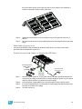
Overview . . . . . . . . . . . . . . . . . . . . . . . . . . . . . . . . . . . . . . . . . . . 389
1 x 20 Setup . . . . . . . . . . . . . . . . . . . . . . . . . . . . . . . . . . . . . . . . . 389
2 x 10 and 2 x 20 Setup . . . . . . . . . . . . . . . . . . . . . . . . . . . . . . . . 389
User Guidelines for Fader Wings . . . . . . . . . . . . . . . . . . . . . . . . . 392
13
14
Ion Operations Manual
Introduction
Welcome to the Ion Operations Manual. This manual is a comprehensive resource for users of the
Ion control system.
Note:
For information on using show control with your system, see the Eos Family Show
Control User Guide, which is available for download at www.etcconnect.com.
This chapter contains the following sections:
Introduction
•
Using this Manual . . . . . . . . . . . . . . . . . . . . . . . . . . . . . . . . . . .2
•
Register Your Ion . . . . . . . . . . . . . . . . . . . . . . . . . . . . . . . . . . . .3
•
Help from ETC Technical Services. . . . . . . . . . . . . . . . . . . . . .3
•
Important Concepts . . . . . . . . . . . . . . . . . . . . . . . . . . . . . . . . . .4
•
Other Reference Materials . . . . . . . . . . . . . . . . . . . . . . . . . . . .8
•
Online Eos Family (Eos Ti, Eos, Gio and Ion) User Forums .8
1
Using this Manual
In order to be specific about where features and commands are found, the following naming and
text conventions will be used:
•
Facepanel buttons are indicated in bold [brackets]. For example, [LIVE] or [Enter].
Optional keys are indicated in <angle brackets>, for example, <Cue> or <Sub>.
•
Browser menus, menu items, and commands you must perform are indicated in bold
text. For example: In the File menu, click Open. Or: Press [Record] [Preset] [Enter].
•
Alphanumeric keyboard buttons are indicated in all CAPS. For example, TAB or CTRL.
•
Keys which are intended to be pressed or held simultaneously are indicated with the
“and” symbol. For example, [Load] & [Timing Disable].
•
Softkeys and clickable buttons in the Central Information Area (CIA) are indicated in
bold {braces}. A note about <More SK> (more softkeys): this command is always
indicated as optional, and is only indicated once in an instruction regardless of how
many pages of softkeys exist. This is because there is no way to predict what softkey
page you are on at any given time. Press <More Softkeys> until you find the required
command.
•
References to other parts of the manual are indicated in italics. When viewing this
manual electronically, click on the reference to jump to that section of the manual.
Note:
Notes are helpful hints and information that is supplemental to the main text.
CAUTION:
A Caution statement indicates situations where there may be undefined or
unwanted consequences of an action, potential for data loss or an equipment
problem.
WARNING:
A Warning statement indicates situations where damage may occur, people may
be harmed, or there are serious or dangerous consequences of an action.
Please email comments about this manual to: [email protected]
2
Ion Operations Manual
Register Your Ion
Registering your Ion system with ETC ensures that you will be notified of software and library
updates, as well as any product advisories.
To register your console, you will need to enroll in “My ETC,” a personalized ETC Web site that
provides a more direct path of communication between you and ETC.
Register now at http://www.etcconnect.com/product.registration.asp.
Help from ETC Technical Services
If you are having difficulties, your most convenient resources are the references given in this user
manual. To search more widely, try the ETC Web site at www.etcconnect.com. If none of these
resources is sufficient, contact ETC Technical Services directly at one of the offices identified below.
Emergency service is available from all ETC offices outside of normal business hours.
When calling for assistance, please have the following information handy:
•
Console model and serial number (located on back panel)
•
Dimmer manufacturer and installation type
•
Other components in your system (Unison®, other control devices, etc.)
Americas
Electronic Theatre Controls Inc.
Technical Services Department
3031 Pleasant View Road
Middleton, WI 53562
800-775-4382 (USA, toll-free)
+1-608 831-4116
[email protected]
Asia
Electronic Theatre Controls Asia, Ltd.
Technical Services Department
Room 1801, 18/F
Tower 1, Phase 1 Enterprise Square
9 Sheung Yuet Road
Kowloon Bay, Kowloon, Hong Kong
+852 2799 1220
[email protected]
Introduction
United Kingdom
Electronic Theatre Controls Ltd.
Technical Services Department
26-28 Victoria Industrial Estate
Victoria Road,
London W3 6UU England
+44 (0)20 8896 1000
[email protected]
Germany
Electronic Theatre Controls GmbH
Technical Services Department
Ohmstrasse 3
83607 Holzkirchen, Germany
+49 (80 24) 47 00-0
[email protected]
3
Important Concepts
Before using Ion, you should read and familiarize yourself with the concepts defined below. You will
find that understanding these terms and concepts will improve your efficiency with Ion.
C h a n n e l = F i x tu r e
A fixture is defined as a group of related addresses that together control a device. An
examples of a fixture would be an ETC Revolution. This moving light contains 31
parameters that together allow you to perform various functions such as pan and tilt. Each
of these attributes is addressed by a different output.
Ion treats fixtures and channels as one and the same. Unlike former ETC consoles where
a fixture occupied one channel for each parameter, Ion assigns each fixture a single
channel number. Individual parameters are then associated with that channel as additional
lines of channel information.
Output
Outputs are the method by which level changes to channels are conveyed to attached
devices. These outputs are patched to channels. In its simplest form, an output is the data
signal sent from the console to turn on a light or modify a fixture parameter.
Record Target
A record target is any data location that you can store data using a [Record] or [Record
Only] command. Examples of record targets are cues, palettes, presets, and macros.
Move Instruction
A move instruction is any change to a parameter from its previous stored value. Any change
to a channel’s intensity is a move instruction. Any change to a channel’s pan or tilt is a move
instruction. Any change to a channel’s color mixing is a move instruction, and so on.
M a n ua l D a t a
Manual data is any value set for a channel via the command line. Manual data will remain
at its value until a move instruction is provided for it.
Syntax Structure
Most instructions can be entered into Ion through the command line. The Ion command line
expects instructions to be entered in a specific structure, or syntax.
Generally speaking, the order of syntax can be described as:
•
•
•
What are you trying to affect? (Channel, group)
What do you want it to do? (Change intensity, focus, pan and tilt)
What value do you want? (Intensity at full, Iris at 50)
Naturally other commands will be used in the course of programming your show, but most
other functions are modifiers of these three basic steps: modifying the channel(s) you are
are working with, determining what parameters of those channels you are impacting, and
what value you want them to assume. When working with record targets, the syntax is
similar.
Note:
4
Not all actions on Ion must be entered from the command line, although many will
result in a command line instruction. Other actions bypass the command line
entirely.
Ion Operations Manual
Enter
Since the command line can receive multiple edits and instructions at once, it is necessary
to let Ion know when you have completed your instruction in the command line. This is done
with the [Enter] key.
There are some commands which are self-terminating, and therefore do not require [Enter]
to be pressed. Some (but not all) of these commands are:
•
•
•
•
•
[Out]
[Shift] & [+]
[Shift] & [-]
[Full] [Full]
Actions from the direct selects
Parameters and Parameter Categories
Ion divides fixture parameters into four major parameter categories: Intensity, Focus, Color, and
Beam. These are the parameters in each category:
•
Intensity . . . . . . . . . . Intensity
•
Focus . . . . . . . . . . . . Pan and Tilt
•
Color . . . . . . . . . . . . . All color parameters (such as color wheel, CMY, scrollers, and
so on).
•
Beam . . . . . . . . . . . . Any parameter not covered in the other categories.
Tracking vs. Cue Only
Ion is, by default, a tracking console. This means two things. First, tracking relates to how
cue lists are created. Once data is in a cue list, it will remain a part of that cue list, at its
original setting, and track forward through subsequent cues, until a new instruction is
provided or until it is removed from the cue list using filters or null commands.
Secondly, tracking relates to how changes to cue data are handled. Unless otherwise
instructed by a Cue Only command, changes to a parameter in a cue will track forward
through the cue list until a move instruction (or block command) is encountered.
It is possible to change the default setting of Ion to “Cue Only”. This prevents changes from
tracking forward into subsequent cues, unless overridden with a track instruction.
Ion also has a [Cue Only/Track] button that allows you to record or update a cue as an
exception to the default setting. Therefore, if the console is set to Tracking, the button acts
as Cue Only. If console is set to Cue Only, it behaves as a Track button.
Introduction
5
Move Fade
Move Fade is a lighting control philosophy which determines how cues are played back. Ion
adheres to this philosophy.
In a Move Fade system, parameters do not change from their current setting until they are
provided a move instruction in a cue or are given a new instruction manually.
For example, in cue 1, channel 1 has been given an intensity value of 50%. This value does
not change until cue 20, where channel 1 is moved to 100%. Therefore, channel 1 has a
tracked intensity value of 50% in cues 2-19. If the user applies a manual intensity value of
25% while sitting in cue 5 (for example), that channel will stay at 25% until Cue 20 is
recalled - because 20 is the next cue in which channel 1 has a move instruction. The
original intensity of 50% will not be reapplied in subsequent cues unless specifically called
out by the cue or manually performed.
Cue List Ownership
Ion is capable of running multiple cue lists. In a multiple-cue-list console, cue list ownership
is an important concept. Cue list ownership is determined by the cue from which a channel
is currently receiving its value. In Live, a parameter is considered to be “owned” by a cue
list when it is receiving its current value from that cue list.
When alternating between cue lists in sequential playback, an active cue list does not
necessarily own a channel unless that list has provided the last move instruction for that
channel. For example, assume a channel is owned by cue list 1 and is at a tracked value.
If a cue from another cue list is executed and provides a move instruction for the channel
in the new cue, the channel is now owned by the second cue list. It will not return to cue list
1 until that cue list provides a move instruction for the channel.
Assert may be used to override this default behavior, allowing a cue list’s control over a
channel to resume, even when the channel’s data is tracked.
This rule is not followed when executing an out-of-sequence cue. An out-of-sequence cue
is any cue that is recalled via “Go To Cue”, a Link instruction, or manually changing the
pending cue. In general applications, the entire contents of the cue (both moves and tracks)
will be asserted on an out-of-sequence cue.
Block vs. Assert
In previous ETC consoles, placing a block instruction on a channel was a way to treat a
tracked value as a move instruction, both in editing and playback. In Ion, this behavior is
now split up. Blocked channel data is an editing convention only, and it prohibits tracked
instructions from modifying the associated data. Blocked data has no impact on playback;
the channels will continue to play back as though they were tracks. Assert is used to force
playback of a tracked/blocked value.
6
Ion Operations Manual
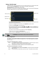
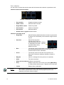
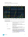
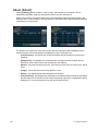
Live and Blind
Live and Blind are methods to view and edit data in your show files. When you press the
[Live] key, the screen will show you the live display. When you press [Blind], you will see
the blind display. In either case, you may use the [Format] key to alter how the data is
displayed (see Using [Format], page 39).
When in Live, the data displayed represents the data being sent from the console at that
moment. In other words, the parameter data that is “live” on stage. When you edit data in
live, those changes will become active and visible on stage as soon as the command line
is terminated.
When in Blind, the data displayed represents data from the record target you choose to
view (cues, presets, palettes, and so on). When you edit data in Blind, changes will not
automatically appear on stage, since the data you are modifying is not live. This is true even
if the record target you are modifying is active on stage. It is possible to play a cue in Live,
then switch to Blind and edit that cue in blind without affecting levels on stage. Edits in Blind
do not require a [Record] command to be stored. They are considered stored when the
command line is terminated. Any display that is not the Live display is considered Blind, and
the Blind LED will be illuminated. For example, if you open patch, the blue LED on [Blind]
will be lit to show that you are in a Blind display.
HTP vs. LTP
HTP (Highest-Takes-Precedence) and LTP (Latest-Takes-Precedence) are terms used to
define the output of a channel parameter that is receiving data from multiple sources. In
HTP, the highest level of all sources will be executed. In LTP, the most recent level received
will be executed. Cue lists and submasters can operate as HTP or LTP for intensity
parameters only. Non-intensity parameters (NPs) are always LTP. Submasters can operate
as HTP or LTP for intensity. The default is HTP. Ion’s default cue list setting for intensity is
LTP (see HTP/LTP, page 209). Ion’s default submaster setting for intensity is HTP.
HTP
HTP is only applicable to the intensity of a channel. HTP channels will output the level that
is the highest of all inputs. HTP channels are also referred to as “pile-on”, because as
control inputs are added (for example - you may bring up cues and multiple submasters that
all have the same channel recorded at various levels), the system calculates which input
has the highest level for that channel and outputs that level for the channel. As control
inputs are removed (you pull some of the submasters down to zero), the console will adjust
the channel level, if required, to the highest remaining level.
LTP
LTP is applicable to any parameter of any channel. LTP output is based on the most recent
move instruction issued to the channel parameter. Any new values sent to the channel will
supersede any previous values, regardless of the level supplied.
Ion determines the LTP value for a channel, which is overridden by any HTP input values
that are higher than the LTP instruction. This is then finally modified by manual control.
Introduction
7
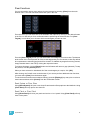
Other Reference Materials
Help System
A keyhelp system is also contained within your system. To access help, press and hold [Help] and
press any key to see:
•
•
•
Note:
the name of the key
a description of what the key enables you to do
syntax examples for using the key (if applicable)
Keyhelp is included on most tangible action buttons on your Ion console. This
includes most softkeys and clickable buttons as well as the traditional keys on the
keypad.
As with hard keys, the “press and hold [Help]” action can be also used with
softkeys and clickable buttons.
O n l i n e E os F a m i l y ( E o s T i , E o s , G i o a n d I o n ) U s e r F o r u m s
You are encouraged to visit and participate in the ETC Eos Family (Eos Ti, Eos, Gio and Ion) User
Forum, accessible from the ETC web site (www.etcconnect.com). This gives you access to an
online community of Eos, Eos Ti, Gio, and Ion users where you can read about other users’
experiences, suggestions, and questions regarding the product as well as submit your own.
To register for the ETC Family (Eos Ti, Eos, Gio and Ion) User Forum:
Step 1:
Step 2:
Step 3:
8
Go to ETC’s community web site (www.etcconnect.com/community). An introduction
page to the online community will open.
You may register for the forum using the “register” link in the introduction or by
clicking the “join” link in the upper right corner of the page.
Follow the registration instructions provided by the community page.
Ion Operations Manual
Chapter 1
System Overview
Inside this chapter you will find general descriptions of your Ion control console, how it fits into a
network control system, and the various areas of user interface.
This chapter contains the following sections:
1
•
System Components . . . . . . . . . . . . . . . . . . . . . . . . . . . . . . . .10
•
Console Geography. . . . . . . . . . . . . . . . . . . . . . . . . . . . . . . . .12
•
Cleaning Ion . . . . . . . . . . . . . . . . . . . . . . . . . . . . . . . . . . . . . . .14
•
Outputting DMX . . . . . . . . . . . . . . . . . . . . . . . . . . . . . . . . . . . .14
•
Console Capacities . . . . . . . . . . . . . . . . . . . . . . . . . . . . . . . . .15
System Overview
9
System Components
Console
Ion is designed from conception as a fully integrated controller for conventional lights and
multi-parameter devices (for example: moving lights, LEDs, color scrollers, gobo wheels). Attention
to detail across all areas of the system design and architecture allows you the utmost flexibility and
customization of use.
Ion allows designers and programmers to develop a mutual vocabulary for control. This
implementation of simple and uniform syntax for control provides a solid foundation for both
experienced and inexperienced users.
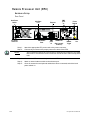
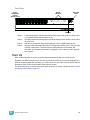
Remote Processor Unit (RPU)
The RPU can be used as the primary, backup processor for the system, a client, or for primary
playback in installations that do not require a facepanel after initial programming is completed.
For more information, see the appendix Remote Processor Unit (RPU), page 383.
Remote Video Interface (RVI)
The remote video interface allows remote interaction with the lighting control system. This can be
for display purposes only. Additionally, with a mouse and alphanumeric keyboard attached, the RVI
can be used as a remote programming station. The RVI provides supports for a maximum of two
DVI or SVGA monitors, 1280x1024 minimum resolution.
For more information, see the appendix Remote Video Interface (RVI), page 379.
Radio Focus Remote (RFR)
The RFR provides wireless control of key front panel functions.The base station for the RFR can be
networked into the system, or can connect to a console or remote device using the USB interface.
For more information, see the appendix Remote Control, page 377.
iRFR and aRFR
The iRFR and aRFR provide wireless control of key front panel functions.See “iRFR” on
page 388.See “aRFR” on page 388.
10
Ion Operations Manual
Gateways
Ion is part of a fully networked system capable of direct output of both ETCNet2 and Net3.
Gateways can be configured to listen to either ETCNet2 or Net3 and provide interface to devices in
the lighting system that do not accept network communication directly. Gateways are provided for
DMX/RDM output, show control input and output and analog input and output.
• Net3 to DMX/RDM gateways are provided with a maximum of four outputs, which can be
male, female, or terminal strip.
Note:
Net3 Gateways only support RDM when in Net3 mode.
• Show Control Gateway supports MIDI In/Thru and Out and SMPTE In.
• I/O Gateway supports 24 analog inputs, 16 SPDT contact closure outputs, and RS-232 serial
protocol.
1
System Overview
11
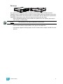
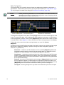
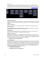
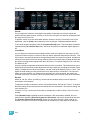
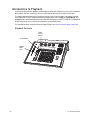
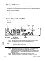
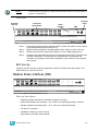
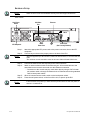
Console Geography
Below is a diagram of the Ion console with references made to specific areas of use. The terms and
names for each area and interface are used throughout this manual.
Parameter category/
Paged encoders
encoder page buttons
Power button
Softkeys
USB port
LCD screen
Blackout and
Grandmaster
Navigation keys
Playback
controls
Current Ion
Rear panel
Control
keypad
IEC receptacle
Level
wheel
Audio Ports
MIDI Out and In
(not currently
supported)
Remote
trigger
port
Phone
Remote
Port
Hard power switch
Original Ion
Rear panel
VGA port
IEC receptacle
DVI video
ports
USB
ports
Ethernet
port
Audio Ports
Hard power switch
VGA port
(blue)
12
(not currently USB
supported)
ports
Ethernet
port
DMX ports
1 and 2
MIDI Out and In
Remote
trigger
port
Phone
Remote
Port
Dual DVI video DMX ports
port (white)
1 and 2
Ion Operations Manual
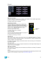
Terminology
Pow e r Button
The power button on the front of the console is used to power up or power down. A separate power
switch, located in the rear panel, can be used to disconnect power from the console’s internal
components.
WARNING:
Before servicing Ion, you must switch off the power on the rear panel and
disconnect the power cord completely.
US B Ports
One USB port is provided on the front of the console to connect any USB storage device. An
additional USB ports on the rear panel can be used to connect peripherals such as an
alphanumeric keyboard, pointing device, or touchscreen control for external monitors.
.
CAUTION:
The USB ports cannot be used for charging devices such as cell phones.
Encoders
Encoders and the LCD (see below) for control of non-intensity parameters are provided at the top
center of the console. The four encoders are pageable controls, which are populated on the LCD
with the parameters used in your show.
LCD
This display accompanies the CIA as an additional user interface. This LCD offers you softkeys,
encoder information, and an additional view of the command line.
Load
The load button is located above the fader pair at the bottom of the LCD and is used to load the
specified cue.
Control Keypad
The control keypad area is divided into three general sections including record targets, numeric
keypad and modifiers, and special function controls.
Level Wheel
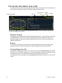
Adjusts intensity for selected channels. It also provides scrolling and zoom functions in various
modes.
Navigation Keypad
Used for quick access to the live and blind displays, format, paging, and navigation within displays.
Parameter Category/ Encoder Page Buttons
Parameter buttons are used to select parameter categories and change encoder pages. To post a
parameter category to the command line, use [Shift] & [Encoder Page Button].
IEEE Ethernet 802.3 Ethernet Port
Ethernet port for connection to a network switch, network gateways, and accessory devices.
1
System Overview
13
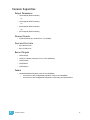
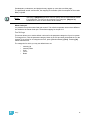
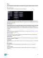
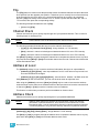
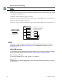
Littlites®
You may connect a Littlite to the side of your Ion console.
Littlite XLR 3-Pin Female Connector
2
1
3
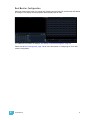
D i m m in g L i t t l it e s
Attached desk lamps can be dimmed either with the desk lamp control knob on the side of the
console, or from the software.
Desk lamp controls are found in Setup>Desk>Brightness Settings. The {Desk Lamp} slider has
a range of 0% (dimmest) to 100% (brightest). The default setting is 0%. The console will set the
desk lamp to this setting on startup of the application. See “{Brightness Settings}” on page 108.
The desk lamps can also be controlled by holding down [Displays] and rolling the level wheel.
Cleaning Ion
Should the exterior or LCD of your Ion require cleaning, you may gently wipe them with a
dampened (not dripping), non-abrasive paper towel or soft cloth.
If this does not clean the console sufficiently, you may apply some window cleaner (containing
ammonia is fine) to the cloth and repeat the process until clean.
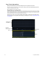
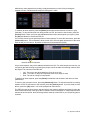
O u t p u t ti n g D M X
In order to output levels from Ion, you can either use the DMX ports on the back of the console, or
to output over a network, you may connect a Net3 gateway or Net2 node. If your devices receive
Net3 or ETCNet2 directly, no gateway or node is required.
Ion has two DMX ports. To output, connect one 5 pin XLR cable per port. The first port will default
to outputting the first universe of DMX, addresses 1-512, and the second port to the second
universe, outputting addresses 513-1024. See Local DMX Outputs, page 351 for information on
reconfiguring the DMX ports.
Nodes and gateways will function with Ion out of the box without previous configuration. However if
custom configuration is required, you will need to use either NCE (Network Configuration Editor) or
GCE (Gateway Configuration Editor). GCE is installed on Ion by default and can be accessed in
ECU>Settings>Maintenance>Gateway Configuration Editor (GCE). NCE can be installed on
the console or a Windows® PC for configuration.
For more information on Net3 gateways or Net2 nodes, see the product literature that accompanied
the hardware or download it from our website at www.etcconnect.com.
14
Ion Operations Manual
Console Capacities
Output Parameters
• 1,024 outputs (DMX channels)
-or• 1,536 outputs (DMX channels)
-or• 2,048 outputs (DMX channels)
-or• 3,072 outputs (DMX channels)
Channel Counts
• 10,000 channels (any number from 1 to 99,999)
Cues and Cue Lists
• Up to 999 cue lists
• Up to 10,000 cues
Record Targets
• 1,000 Groups
• 1,000 x 4 Palettes (Intensity, Focus, Color and Beam)
• 1,000 Presets
• 1,000 Effects
• 1,000 Macros
Faders
• 1 dedicated Master Playback, with Go and Stop/Back
• a maximum of 200 configurable playbacks, with Go and Stop/Back
• a maximum of 300 configurable submasters, with Bump and Assert/Select
1
System Overview
15
16
Ion Operations Manual
Chapter 2
System Basics
This chapter explains the base level procedures for setting up, navigating, and understanding how
to operate Ion.
This chapter contains the following sections:
2
System Basics
•
Setting Up the Hardware . . . . . . . . . . . . . . . . . . . . . . . . . . . . .18
•
Power . . . . . . . . . . . . . . . . . . . . . . . . . . . . . . . . . . . . . . . . . . . .19
•
Your First Interaction. . . . . . . . . . . . . . . . . . . . . . . . . . . . . . . .20
•
The Central Information Area (CIA) . . . . . . . . . . . . . . . . . . . .22
•
Using the Browser . . . . . . . . . . . . . . . . . . . . . . . . . . . . . . . . . .24
•
Display Control and Navigation . . . . . . . . . . . . . . . . . . . . . . .28
•
Graphical User Interface (GUI) Display Conventions . . . . . .31
•
Using [Format] . . . . . . . . . . . . . . . . . . . . . . . . . . . . . . . . . . . . .39
•
Using Flexichannel . . . . . . . . . . . . . . . . . . . . . . . . . . . . . . . . .36
•
Encoders . . . . . . . . . . . . . . . . . . . . . . . . . . . . . . . . . . . . . . . . .45
•
Moving Light Controls. . . . . . . . . . . . . . . . . . . . . . . . . . . . . . .46
•
Using Softkeys . . . . . . . . . . . . . . . . . . . . . . . . . . . . . . . . . . . . .47
17
Setting Up the Hardware
Follow these steps to prepare your Ion for use.
Step 1:
Step 2:
Note:
Step 3:
Step 4:
Step 5:
Step 6:
Place your console on a firm, level surface. Be sure to leave space for access to the
rear of the console. You will need to connect several items to the ports on the back.
Connect any monitors to the proper ports on the back of the console.
Ion supports up to 2 monitors, either 2 DVI -D monitors or 1 DVI-D and 1 VGA.
Connect the keyboard and mouse. Attach to the appropriate connector on the back of
the console.
If you will be connecting to an Eos Family network, connect the appropriate Ethernet
(CAT 5 or better) cable to the Ethernet port on the back of the console.
If you plan on using the DMX ports on the back of Ion to control your lighting system,
attach the appropriate DMX connector and cable to the desired port. These ports
default to output DMX universes one and two. Configuration is required to use any
other universe. For more information, see Local DMX Outputs, page 351 in the ECU
appendix.
Attach the appropriate IEC power cable for your location to the IEC connector on the
back of the console, just above the power switch.
Your console hardware is now ready to be powered up.
18
Ion Operations Manual
Power
Power Up the Console
Step 1:
Step 2:
Note:
Attach the appropriate power cable to the IEC connector on the rear of the console.
Press the I/O switch (I is “on”) next to the IEC connector on the rear of the console to
turn power on. This will provide power to all internal electronics.
You need to wait about 30 seconds between steps 2 and 3.
Step 3:
Note:
Press the power button, located in the top left corner of the console, above the USB
port. The button LED will illuminate blue to indicate the console is running. The
console will boot up into the Ion environment. The Ion system is now ready for use.
In the future, you may go straight to the welcome screen by adjusting a setting in
the ECU. See Open in Shell, page 337 in the ECU appendix.
P o w e r D o w n th e C o n s o l e
Step 1:
Step 2:
After saving your show (see below), in the browser menu select Power Off Device.
A dialogue box opens asking you to confirm.
Confirm this command by clicking {OK} in the dialog box. The console will power
down.
-OrStep 1:
Step 2:
2
Press the power button, located on the face panel. A dialogue box opens asking you
to confirm.
Confirm this command by pressing {OK} in the dialog box or by pressing the power
button again. The console will power down.
Note:
Ion is a persistent storage console. Therefore if you shut down your system
without saving the show file, you will return to the same place in your show when
you reboot.
Note:
The console will display an improper shutdown message on the next power up if
the console was not powered down from the browser menu or welcome screen.
System Basics
19
Your First Interaction
When you first start up Ion, you will immediately enter the Ion software environment.
Since Ion can be set up with one or two monitors, what you will first see depends partly upon the
number of monitors you are using.
Single Monitor Configuration
When using a single monitor, the top half of the initial display screen becomes the primary viewing
area for displayed information. Ion will first open with the live table display on the top (primary) half
of the screen and the CIA on the bottom half of the screen.
When the CIA is open, one line of the playback status display is visible above the double arrows.
You can view more of the playback status display by collapsing the CIA (see Collapse/Expand the
CIA, page 22).
Primary screen live display
Playback
Status Display
Command
line
Tabs
CIA
Initial View - Primary/CIA
20
Ion Operations Manual
D u a l M o n i to r C o n fi g u r a ti o n
When two monitors are used, one monitor will default to showing the CIA, and the other will default
to having the live display and the playback status display open on tabs.
For additional information on displays, see Display Control and Navigation, page 28.
Please see Monitor Arrangement, page 338 for more information on configuring Ion for a dual
monitor configuration.
2
System Basics
21
The Central Information Area (CIA)
The Central Information Area (CIA) is displayed on the lower portion of the screen. By default, the
CIA consists of two primary areas: the parameter display and the browser.
Favorite star
Parameter display
Browser
Double
arrows
CIA lock
Parameter category button labels
Parameter Display
This display shows the parameters available for patched channels. It is also where you can select
which parameters to view in live or blind, or select parameters for command line control. The
parameter display will dynamically change depending on the channel (fixture) selected and its
applicable parameters.
Browser
The browser is the interface for numerous functions including saving a show, opening a show,
changing settings, viewing record target lists, opening displays and many other functions.
Collapse/Expand the CIA
It is possible to collapse the CIA from view. To do this, you can click the double arrow icon centered
above the CIA. The CIA will collapse from view, exposing a larger viewing area of whatever display
is visible above the CIA. The double arrows will move to the bottom of the screen.
To expand the CIA into view again, click the double arrow at the bottom of the screen. The CIA will
reopen.
22
Ion Operations Manual
Lock the CIA
You can lock the CIA in place to prevent it from being collapsed.
To lock the CIA, click on the lock above the browser. The double arrow above the CIA will
disappear and the lock will “lock”.
To unlock the CIA, click the sunken lock again and the double arrows will reappear.
Favorite CIA Display
You can select a favorite default display for the CIA that will
show when [Displays] is pressed. The standard default display for the CIA is the Browser.
The favorite display will show a gold star icon at the top of the CIA by the double arrows & lock.
Displays that can be selected as a favorite, but are currently not, will show a grey star at the top of
the CIA. Click on the grey star to make that display your favorite. That display will now be the new
default display for the CIA. Displays that show up in the CIA but can not be the default display will
not show the star icon.
The following displays can be set as the favorite CIA default:
• About
• Browser (default)
• Color Picker
• Direct Selects
• Virtual Sliders
• Virtual Keypad
• ML Controls
• Encoder Information Screen
• Effects Status
Locking the Facepanel
It is possible to lock out the facepanel, which prevents any actions from the command line or CIA.
To lock out the facepanel, press [Shift] & [Escape]. To unlock the facepanel, press [Shift] &
[Escape] again.
Note:
2
System Basics
This will also lock any fader wings or USB connected peripherals.
23
Using the Browser
To use the browser, you must first draw focus to it by clicking anywhere in the browser area of the
CIA or by pressing the [Displays] key. If the browser is not visible, double pressing
[Displays]>Browser will always bring up the browser.
When focus is on the browser, the window border highlights in gold. The scroll lock LED illuminates
red and the paging keys will now control selection in the browser.
Selection bar
Menu arrows
Opened menu
Sub menus
Scroll bar
• Use the page arrow keys to move the selection bar up and down the list. You can also use the
level wheel to scroll through the list.
• When the bar highlights the desired menu, press [Page ] to open the menu.
• Continue pressing [Page ] to open submenus.
• Scroll to the item you wish to open using [Page ] or [Page ] and then press [Select]. You
may also click the item you wish to open and then press [Select]. You can also use the level
wheel to scroll in the browser.
• If you wish to close a submenu scroll to that item and press [Page ].
• To draw focus to the CIA press the [Displays] key.
• Additional presses of [Displays] will minimize or restore the CIA.
Note:
The [Select] key can be used to confirm a choice in the browser.
Virtual Keyboard
It is possible to open a virtual keyboard in the CIA which mimics the hard keys found on the actual
Eos keypad. The keypad will not match the facepanel on Ion. This virtual keyboard is accessible
from the browser.
To open the Virtual Keyboard on a monitor:
Step 1:
Step 2:
Go to Browser>Virtual Controls>Virtual Keyboard. A window will open in the CIA
displaying your monitor placement options for the keyboard.
Click the placement option in which you want the keyboard to appear.
To close the Virtual Keyboard on a monitor:
Step 1:
Step 2:
24
Go to Browser>Virtual Controls>Close Module. The placement screen will appear
again in the CIA.
Click the placement of the module you wish to close. The module will be removed.
Ion Operations Manual
Fader Module
If you prefer to have faders available to you, the monitors can be populated with virtual faders,
called fader modules.
To open the fader module on a monitor:
Step 1:
Step 2:
Go to Browser>Virtual Controls>Fader Module. A window will open in the CIA
displaying your monitor placement options for the module.
Click the placement option in the CIA in which you want the module to appear.
To close the fader module on a monitor:
Step 1:
Step 2:
Go to Browser>Virtual Controls>Close Module. The placement screen will appear
again in the CIA.
Click the placement of the module you wish to close. The module will be removed.
Using Direct Selects
Direct selects allow access to a number of controls, including a channel select display. If there are
more items than can be viewed at once, you may view subsequent pages by using the page buttons
({Page }, {Page }) by the direct selects.
Selecting Channels with Direct Selects
Channel direct selects are highlighted when selected. Channel selection is generally an additive
process, if channels 1-5 are selected, pressing {Channel 6} adds channel 6 to the selection,
leaving channels 1-5 also selected. Pressing {Channel 6} again will deselect the channel.
If you have labeled channels in patch, those labels will be displayed above the channel number
when viewing channels in the direct selects.
It is possible to double hit a channel button. This selects that channel and deselects any previously
selected channels.
• {Channel 1} - adds channel 1 to currently selected channels, if not currently selected.
• {Channel 1} {Channel 10} - adds channels 1 and 10 to currently selected channels.
• {Channel 1} {Channel 1} - selects channel 1, deselects all other channels.
• {Page } - pages direct selects down by one page.
• {Page } - pages direct selects up by one page.
Direct Selects
Ion gives you the option of opening direct select modules on the monitors.
To open the direct selects on a monitor:
Step 1:
Step 2:
Go to Browser>Virtual Controls>5 x 10 Direct Select Module. A window will open
in the CIA displaying your monitor placement options for the module.
Click the placement option in which you want the module to appear.
To close the direct selects on a monitor:
Step 1:
Step 2:
Go to Browser>Virtual Controls>Close Module. The placement screen will appear
again in the CIA.
Click the placement of the module you wish to close. The module will be removed.
For information on populating direct selects see Organizing the Direct Selects.
2
System Basics
25
Organizing the Direct Selects
You have considerable flexibility in how you organize the direct selects. They may be arranged to
display one of several different types of data.
To choose which information to view:
Step 1:
Click the {Select} button for any block of direct selects. You will be offered the
following choices to view: Channels, Groups, Intensity Palettes, Focus Palettes,
Color Palettes, Beam Palettes, Presets, Macros, Effects, and Snapshot.
Click the button for the data you wish to view and the associated direct selects will
populate with any recorded information of that type. If there is no recorded information
of that type the block of buttons will remain empty but will populate with data of that
type as associated record targets are stored.
You may also click {Select} again, without choosing any option, to return to the
previous state.
Step 2:
Step 3:
You can increase/decrease the size of any set of direct selects by pressing the {20/50} button,
which will change the display between one set of 50 buttons and two sets of 20 buttons. Or you may
press the {100} button to expand to a full set of 100 buttons. Press {100} again to switch back to the
previous view.
You may also press the {Expand} button (located beneath the {Select} button) to expand a set of
direct selects to full screen. Press {Expand} again to return the set to its previous size and
mapping. Century and Millennium buttons will display when direct selects are in expand mode.
When the direct selects are opened on a tab, two sets of direct selects will be displayed.
Direct Selects in Flexi Mode
Direct selects can be placed into a flexi mode, which will remove
empty tiles. When {Select} is pressed, the {Show Flexi} button
will display.
On
Off
Note:
A single empty direct select tile may remain if the adjacent direct select tiles are
not sequential. This is to allow an easy way to insert a new direct select between
the existing ones.
.
Show Flexi is Off
Show Flexi is On
26
Ion Operations Manual
Clear Functions
You can access the various clear options from the browser by selecting {Clear} from the main
browser menu. The clear functions window will open in the CIA.
From this menu you can select one of the available clear options by clicking on the desired button
in the CIA. Ion will ask you for a confirmation before performing the selected clear. For {Clear
Targets}, Ion will allow you to choose which record targets you want to clear.
From the {Clear Targets} screen you can select which record targets you wish to clear. The buttons
at the center of the CIA represent all of the record targets that you can choose to clear. By default
all components are selected (gray) and will be cleared. To withhold any targets from being cleared,
simply deselect them in the CIA by clicking the respective button.
To reselect all targets, click the {Reset} button and all buttons will return to gray (selected). To stop
the process, click the {Cancel} button.
When you have selected or deselected all of the record targets you require, click {OK}.
After clearing, the CIA will return to the browser. If you want to perform additional clear functions,
you must select {Clear} from the browser again.
To exit the clear functions screen without clearing, press the [Displays] key at any time or select a
clear button and then select {Cancel} from the confirmation screen.
Reset System vs Clear Show
Using {Reset System} will open a new show file and reset the Setup options to their defaults. Using
{Clear Show} will only open a new show file.
Reset Patch vs Clear Patch
Using {Reset Patch} will clear your patch and set it to a 1-to-1 patch. Using {Clear Patch} will only
clear out the patch.
2
System Basics
27
Display Control and Navigation
Opening and Closing Displays
The live/ blind display will always open as tab 1. The playback status display will always open as tab
2. Neither of these displays can be closed.
Other displays are numbered as they are opened. Tab numbering is useful for navigating to views.
Displays can be opened and closed in different ways, depending on the display. Many displays are
accessible from the browser, while other displays are accessible from the LCD softkeys. The blind
displays of record targets (also called “lists”) can be quickly accessed by double pressing the record
target button (for example, [Preset] [Preset] opens the preset list).
From the browser
Open and navigate the browser as described in Using the Browser, page 24. When you open a new
display (such as the cue list index, group list, or patch) and it is posted in a tab view, it will open on
monitor 2. If the display does not open as a tab view (such as “setup” or the browser) it will open in
the CIA.
Again, any time you wish to return to the browser, simply press [Displays] and then {Browser} and
it will be made available.
From the hardkeys
You can open list views of any record target by double-pressing the key for the desired record
target.
From the LCD softkeys
To open any displays accessible from the softkeys, press [Displays]. The softkeys will repaint to
display:
•
•
•
•
•
•
•
•
•
•
•
Effect Status
Color Picker
Patch
Setup
Browser
Magic Sheet
Command History
Curves
Pixel Maps
Show Control
Mirror
Any of these softkeys will open the associated display with a single press.
Closing Displays
To close any tab display, select the display by using the [Tab] key or other means of navigation.
When the desired display is active, press [Escape] to close it.
To close a display in the CIA, press the [Display] key and the browser will reappear.
To close all displays except for the live/blind display and the playback status display (tabs 1 and 2),
press [Shift] & [Tab].
28
Ion Operations Manual
Selecting Displays
When a display is selected, the screen is highlighted in a gold border and the display name (such
as “1. Live Channel”) will be in gold as well. When a display is not selected, there is no border and
the tab name is gray.
If a display is already open, it can be selected in the following ways:
• Press [Tab] to change focus from the currently selected tab to the tab immediately to the right.
If no tabs are to the right, the selection moves to the first tab on the left of all available monitors.
• Press [Tab] & [n], where “n” represents the tab number of the desired tab.
• Press [Live] or [Blind] to automatically bring live/blind into focus. If there are multiple
instances of live/blind, pressing [Shift] + [Live] / [Blind] brings the next live/blind tab into
focus.
• Double press a record target button (such as [Preset] or [Submaster]) to either open the
associated display or select it if it is already open.
Moving Displays
To move the active display from one monitor to another, press and hold the [Tab] key and use the
page arrow keys to move the display in the direction of the desired screen. One press of the left or
right page keys will move the display to the next screen in that direction. To move it back, press the
opposite arrow key.
Scrolling within a Display
By default the page keys will advance/retreat a display by one page per press. However, to scroll
through displays you may press the [Scroll Lock] key on the keypad. The LED on the button
illuminates red when in scroll lock mode.
Scroll lock is a toggle state. When scroll lock is first pressed:
• [Page ] - scrolls table, spreadsheet and channel views down,
• [Page ] - scrolls table, spreadsheet and channel views up,
• [Page ] - scrolls table and spreadsheet views right,
• [Page ] - scrolls table and spreadsheet views left.
2
System Basics
29
Expanding Displays
[Expand] allows a tab to be viewed across multiple external monitors.
To expand a display to an adjacent monitor, press [Expand] & [Page ] if in table views or
[Expand] & [Page ] if in either view.
To collapse an expanded view, press [Expand] & [Page ] if in table views or [Expand] & [Page
] if in summary views.
Note:
Please note that you must have two monitors attached to Ion to use the [Expand]
feature.
If the display you are expanding is at the right most position, the display will
expand onto the first (or left most) monitor.
Z o o m i ng D i s p l a y s
You may zoom in and out on displays. To do this, press and hold the [Format] button and scroll the
Level Wheel to alter the display. Scrolling the wheel up zooms in. Scrolling the wheel down zooms
out. Zooming the channel summary display when it is in 100 channel mode is not supported. You
can also zoom by holding down the left mouse button and rolling the scroll wheel on a mouse.
30
Ion Operations Manual
Graphical User Interface (GUI) Display Conventions
Ion relies on many traditional ETC indicators which you may be familiar with, as well as some new
ones. This section identifies the graphical and colorful conventions used in Ion to indicate
conditions to you.
Indicators in the Live/Blind Display
This is the live/blind summary view.
Note:
The color and text conventions described below apply regardless of the format of
live/blind being used (see Using [Format], page 39).
Channel Number
Straight line under
channel heading
Intensity data (I)
Effect data
No other parameter
categories
Wavy line under
channel heading
Intensity data (I)
Focus data (F)
Color data (C)
Beam data (B)
F, C, B icons
when collapsed
2
System Basics
Conventionals
Most of the channels in the above image are conventional
channels (intensity is the only available parameter).
Conventionals have a straight line beneath the channel
number. They also display only the top field, intensity, as
no other parameters are available on a conventional
channel.
Moving Lights or Multi-parameter Devices
Several channels in the image are moving lights
(possessing more parameters than just intensity).
Moving light channels have a wavy line beneath the
channel number as well as parameter category indicators
at the bottom of the channel.
This view also has additional data fields beneath intensity
(F, C, B). This information can be suppressed by pressing
and holding [Data] and any of the encoder paging keys
(Focus, Color, Image, Shutter, or Form). Doing so will
leave only the intensity field and FCB indicators at the
bottom of the channel.
31
Color indicators
Ion uses color to indicate the selection state and information about channel or parameter levels.
Channel numbers/channel headers
Selected
Unselected
Unpatched
Deleted
•
Gray number . . . . . . . . .Unpatched channel number.
•
White number . . . . . . . .Selected channel number.
•
Bright White number . .Channel is parked.
•
Gold number . . . . . . . . .Channel is captured.
•
Gold outline . . . . . . . . .Selected channel.
•
Number with no graphicDeleted channel.
Channel or parameter levels
Note:
32
•
Bright Red . . . . . . . . . . .Manual Data (any data that has been set but not yet stored to
an active cue or submaster) on all consoles using the same
user ID.
•
Dark Red . . . . . . . . . . . .Manual Data (any data
that has been set but not
yet stored to an active cue Different
or submaster) from other User ID
consoles that are using
different user IDs.
•
Blue . . . . . . . . . . . . . . . .The intensity value is higher than in the previous cue.
Non-intensity parameters (NPs) are in blue when any move
instruction has occurred. Unmarked.
•
Green . . . . . . . . . . . . . . .The intensity value is lower than in the previous cue.
Also used in reference marking to indicate a channel is
marked.
•
Magenta. . . . . . . . . . . . .Value is unchanged from the previous cue (tracked).
•
White . . . . . . . . . . . . . . .The value is blocked.
•
White with an underscore Value is auto-blocked.
•
Gray . . . . . . . . . . . . . . . .Default or the value is a null value (from either {Make Null}
or a filter). When nulled, a gray “n” appears next to the value.
•
Yellow . . . . . . . . . . . . . .Data set from a submaster.
When data is in transition (moving), it will appear in a lighter version of its color.
This includes up/down fades for intensity, non-intensity moves from cues,
submaster, and timed manual changes.
Ion Operations Manual
Text Indicators in live/blind
Please note examples of text indicators in the following graphic:
“B”
“Ph”
“R”
“_” (underscore)
“M”
“P”
“I”
“C”
“+”
“Pr”
“N”
“Q 10/4”
“A”
“CP2”
“t”
“MK”
Color conventions listed above apply to text indicators as well. Therefore red indicates a manual
value that must be stored.
Color conventions listed above apply to text indicators as well. Therefore red indicates a manual
value that must be stored.
2
•
_ . . . . . . . . . . . . . . . . . . .Underlined value (white) indicates a system-applied block
(also called an auto-block).
•
A. . . . . . . . . . . . . . . . . . .Indicates the channel or parameter is asserted.
•
B. . . . . . . . . . . . . . . . . . .Indicates the channel or parameter is manually blocked. This
block must be stored.
•
C. . . . . . . . . . . . . . . . . . .Captured Channel
•
I . . . . . . . . . . . . . . . . . . .Channel is controlled by an inhibitive submaster or
grandmaster. When displayed in the Block flag, “I” indicates
a cue level intensity block.
•
IP, CP, FP, BP . . . . . . . .Indicates that the value is referenced to a palette (Intensity,
Color, Focus, or Beam). This text is followed by a number,
indicating which palette is being referenced. This can be
substituted with the palette label if the “Show Reference
Label” setting is activated (see Show Reference Labels, page
107). Holding down [Shift] & [Label] will toggle between the
palette label and palette number.
System Basics
33
34
•
MK . . . . . . . . . . . . . . . . .Indicates the channel is marked for a later cue. The cue
number is indicated in the other categories (see “Q” below).
•
N. . . . . . . . . . . . . . . . . . .Indicates the value is null (from either {Make Null} or a filter).
•
P . . . . . . . . . . . . . . . . . . .Indicates the channel is parked.
•
Ph. . . . . . . . . . . . . . . . . .Indicates the channel is at a preheat level.
•
Pr . . . . . . . . . . . . . . . . . .Indicates that the value is referenced to a preset. This text is
followed by a number, indicating which preset is being
referenced. The preset label may also be shown if this setting
is enabled (see Show Reference Labels, page 107). Holding
down [Shift] & [Label] will toggle between the preset label
and preset number.
•
Q. . . . . . . . . . . . . . . . . . .Found in the non-intensity categories of a marked channel.
The “Q” is followed by a number indicating which cue the
mark is in preparation for.
•
t . . . . . . . . . . . . . . . . . . .The channel has discrete (parameter/category-specific)
timing.
•
+ . . . . . . . . . . . . . . . . . . .Found in place of parameter data in summary view. Indicates
that not all parameters in that category are at the same value.
This indicator is found only in the summary view or in table
views when the parameters are collapsed into a category
view.
•
! . . . . . . . . . . . . . . . . . . .Indicates an ACN, RDM, or dimmer error.
•
ND . . . . . . . . . . . . . . . . .Indicates that a channel has been patched as a non-dim
fixture type.
•
S . . . . . . . . . . . . . . . . . . .Indicates that a channel is stored to a shielded submaster.
•
R. . . . . . . . . . . . . . . . . . .Indicates a manual reference override. Manual changes have
been made that override a previously stored reference (such
as to a palette or preset). Once recorded, the reference will
be broken. If updated, the referenced target will be updated
as well, unless otherwise instructed.
•
M . . . . . . . . . . . . . . . . . .Indicates a mark is placed, but manual, and must be stored.
Is blue when stored.”m” indicates cue is not marking.
Ion Operations Manual
[Data] Key
Pressing and holding [Data] allows you to view the values behind any referenced or marked data.
[Data] exposes the next lower reference level. So if you view a palette reference and press [Data],
the absolute data will be displayed instead. If you are viewing a preset, absolute or palette data will
be displayed, depending on what is contained in the preset.
The [Data] key is also used in combination with the encoder paging keys to change the level of
detail in summary and views, and to select parameters to view in spreadsheet modes.
[Time] Key
Pressing [Shift] & [Time] allows you to view discrete timing data behind any channel parameter.
Keep [Time] held down to page. [Time] exposes channel or parameter specific timing for any
channels in the current cue. The first value is the delay time. If “--” is displayed, there is no delay.
The value to the right of the / is the transition time.
When the [Time] button is pressed on a terminated command line, the selected cue is always
displayed for time modification. To add discrete timing to channels on a terminated command line,
those channels must be reselected.The [Select Last] command can be helpful.See “Select Last”
on page 123.
[Label] Key
Pressing and holding [Shift] & [Label] toggles the view to show reference labels or numbers
depending on what display setting is being used. See “Show Reference Labels” on page 107.
2
System Basics
35
Using Flexichannel
Flexichannel (use of the [Flexi] key) allows you to view only channels meeting a certain criteria in
the live/blind display, therefore removing unwanted data from view. Flexichannel has several
available states which include allowing you to view:
• All channels
• All patched channels
• Manual channels
• All show channels (any channels that have data stored in a cue or submaster)
• Active channels (channels with intensity above zero or a move instruction)
• Selected channels
In flexi mode, any selected channels (including the last channel selection) are always included in
the view. Gaps in channel numbers are indicated by a vertical line between the channels where a
gap in numbering occurs.
To change flexi modes in the live/blind display, press [Flexi] to cycle through the views listed above.
When [Flexi] is held down, the softkeys change to represent all of the available flexi states. You can
select the desired flexi view from those keys.
[Next/Last] can be used to select the next or last channel in the current flexi mode.
[Thru] can be used to view only channels in the current flexi mode (except for selected channels
mode) as long as either the first or last channel in the [Thru] range is included in the current flexi
mode. To include channels not in the current flexi mode, [Thru] [Thru] can be used.
Flexichannel with Timing
You may also engage a “Channels with Timing” flexichannel state by pressing [Flexi] & [Time].
This will display all channels that have discrete timing in the current cue and will remove channels
without discrete timing from view.
You may still press [Shift] & [Time] to view the discrete time behind any parameter or category.
The display will remain in this state until you disengage it by pressing [Flexi] & [Time] again.
View Channels
You may select specific channels to appear in another flexichannel state called “View Channels”.
This state does not exist until you select channels to view. After view channels is activated, it will
appear in the rotation of flexichannel states when [Flexi] is pressed.
To select channels to view:
Step 1:
Step 2:
Step 3:
Select channels on the command line (do not press [Enter]).
Press and hold [Flexi].
Press {View Chans}. The “View Channels” flexi state will be created and the
channels you selected will be visible in it.
The channels you selected will be visible in this flexi state until you select other channels and press
{View Chans} again. At any time, you can access the last channels you defined for this state by
pressing [Flexi] until this state is visible.
To redefine the selected channels in the state, simply follow the steps above again.
36
Ion Operations Manual
Indicators in the Playback Status Display
Indicates the timing for a
category.
If blank, default time is
used and there is no move
instruction
Indicates that timing has
been applied but there is
no move instruction.
Sneak Counter
Color indicators
•
Gold . . . . . . . . . . . . . . . .Any item (cue, list, page) highlighted in gold indicates
“current”.
Outlined in gold indicates “selected”.
•
Red. . . . . . . . . . . . . . . . .Cue fade is in progress (cue list area)
T e x t in d i c a t o r s
2
•
+ (see cue 6) . . . . . . . . .Indicates that there is discrete timing within the associated
cue. Found in the cue display “Timing” area.
•
* (see cue 4) . . . . . . . . . .Indicates the cue has an allfade command. Found in the cue
display “Flags” area.
•
- . . . . . . . . . . . . . . . . . . .Indicates a dark move, a cue that has any non-intensity
parameters moving on channels whose intensity is at 0.
•
x . . . . . . . . . . . . . . . . . . .Indicates that a mark has been placed, but the mark is
broken.
•
A or a (see cues 3&4). . .Indicates an asserted cue. “A” indicates the entire cue is
asserted. “a” indicates a channel or parameter assert only.
Found in the cue display “Flags” area.
•
B or b (see cue 2&5) . . .Indicates a blocked cue. “B” indicates the entire cue is
blocked. “b” indicates a channel/parameter block only. Found
in the cue display “Flags” area.
•
D. . . . . . . . . . . . . . . . . . .AutoMark is disabled.
System Basics
37
•
F9 (see in cue 8) . . . . . .Indicates a follow time associated with the cue (in this case,
9 seconds). Found in the cue display.
•
H4 (see in cue 6) . . . . . .Indicates a hang time associated with the cue (in this case 4
seconds). Found in the cue display.
•
I . . . . . . . . . . . . . . . . . . .Indicates an intensity blocked cue. Found in the cue display
“Flags” area.
•
M or m . . . . . . . . . . . . . .Indicates a marked cue. “M” indicates an AutoMark or a
reference mark that is used by a subsequent cue. “m”
indicates a reference mark that is currently unused by any
subsequent cue (see Using Mark, page 191). Found in the
“Flags” area.
•
P (see in cue 3) . . . . . . .Indicates the cue will preheat. Found in the cue display
“Flags” area.
•
R (see in cue 8) . . . . . . .Indicates the source cue which refers back to an earlier mark
(see Referenced Marks, page 193).
•
E 1*(see in cue 2.5) . . . .Indicates a cue level effects override.
•
M1 (see in cue 3) . . . . . .Indicates a linked macro.
•
Q2/1 (see in cue 6). . . . .Indicates a linked cue.
•
S1 (see in cue 1) . . . . . .Indicates a linked string.
.
Note:
38
For more details on information contained in the playback status display, see
Playback Status Display, page 42.
Ion Operations Manual
Using [Format]
Some displays have multiple formats. When the display is first opened, it opens in its default view.
The default view for Live/Blind is table view, with all parameter categories displayed. When the
default format has been changed, those new settings will be used whenever the display is changed
back to that format.
Live and Blind share formatting. When you change from one format to another format, you are
always working with the same format until you change it. The exception to this is spreadsheet,
which is only available in blind. If you are working in blind spreadsheet, when you return to live you
will be working with the table or summary view, based on which one you were last using.
Summary View
The summary view displays the largest number of channels of any of the formats. Below you can
see channels 1-60 are shown. This format is best used to see large numbers of channels’ intensity
data and/or parameter category data. Individual parameters are not visible in this view.
FCB icons will appear at the bottom of the channel area for channels that have those parameters
patched to them.
Channel numbers
Intensity data
F, C, B data
To collapse the summary view, hold down the [Data] key and press any encoder paging key
(located to the right of the LCD).
Summary View Collapsed
When the summary view has been collapsed to show only intensity data, you may include focus,
color, or beam data in the summary view by holding down the [Data] key and pressing any encoder
paging key (located to the right of the LCD). This displays all categories.
2
System Basics
39
Table View
Table view is available in live or blind. Unlike summary view, table view displays the fixture type
associated with channels and details about each channel’s category or parameter levels.
In live, table view displays all active channel data being output from Ion. In blind, it will display all
data for a single record target (cue, preset, palette) depending on what is viewed. In table view,
focus, color, and beam information can be viewed in either a summary of these three categories.
To expand a category to show detail, press the [Data] key and the associated parameter key. For
example, [Data] & [Color] will change the color category from a summary view to a detailed one.
To collapse a category. press the [Data] key and the associated parameter key. You cannot hide a
category from view.
When a category has been expanded, to hide or reveal only certain parameters, press and hold
[Data] and then select the parameter buttons of the appropriate parameters in the CIA. The
parameters will be displayed or suppressed depending on the current view.
Notice that when you hold down the [Data] button, the buttons of parameters that are currently
selected for viewing will be highlighted in the CIA.
In the table view, a slight space is provided between fixture types, giving a clear delineation
between them. The name of the fixture type is displayed at the top of the section for that fixture.
Channels with only intensity parameters will display the same as in summary view.
Expanded category
Parameter data
Summarized category
Fixtures with only
type-specific
parameters displayed
Fixture types
40
Live Table View
Ion Operations Manual
Spreadsheet (Blind Only)
Spreadsheet format is available only in blind mode. It is useful for viewing channel data and trends
for multiple cues, submasters, palettes, or presets at one time. Cues and other record targets are
displayed on the vertical axis and channel data is visible on the horizontal axis.
Since this is a blind-only view, changes made in this view are immediate and do not require a record
or update.
As with table view, spreadsheet format allows you to choose exactly which parameters you want to
view. Parameters can be expanded/suppressed by holding [Data] and pressing the desired
parameter buttons in the CIA. Category data is not available in spreadsheet, but you may hide all
parameters of a specific category by holding [Data] and pressing the desired parameter category
button (also called “encoder paging keys”). By default, the spreadsheet view displays just intensity.
Cue numbers
2
Channel number
System Basics
Parameters
41
Playback Status Display
The playback status display allows you to view a range of cues in the current cue list, all cue
attributes for those cues, and a view of the fader configurations for 10 pages of 10 faders each (for
a total of 100 visible faders.
Holding down [Time], while a cue is fading, will display the cue category times counting down in the
cue list display area. The default action is to show the total time not the countdown. To always show
the countdown, a {PSD Time Countdown} option is available in Setup, see {Displays}, page 107.
When the {PSD Time Countdown} is enabled, the cue category times will countdown as a cue is
fading. To see the total time, hold down the [Time] key. {PSD Time Countdown} is “disabled” by
default.
When focus is on the playback status display, you can use the paging keys to navigate in the
display. An optional command line for the playback status display is available. The optional
command line must be enabled to use. See “{Displays}” on page 107.
There are three formats for the playback status display. By default, it will be an expanded cue list
format. With the playback status display selected, press [Format] to toggle between the formats.
Expanded Cue List Format
Pressing [Format] with the playback status display active will access this format. In expanded cue
list, the view of the active cue list increases to the full size of the display. The current fader page is
still visible at the bottom of the screen.
Sneak Counter
Fader page
number
42
Fader numbers
Ion Operations Manual
Split Playback Status Display
Pressing [Format] with the playback status display active will access this format. With the playback
status display split, two different cue lists can be displayed at the same time by locking. If both cue
lists are unlocked, they will display the same list.
Note:
Locked cue list
The first time you access the split playback status display, you may need to adjust
the splitter bar between the two lists to see the second list.
Unlocked cue list
Optional
Command Line
2
System Basics
43
Fader Display Format
Pressing [Format] with the playback status display active will access this format.
Current cue list
Cues
Timing data
Fader Pages
1-10
Cue flags
Cue attributes
Master cue list timeline
Submasters
Faders1-10
Other cue list
44
Ion Operations Manual
Encoders
The encoders are one of two ways to control the non-intensity parameters (NPs) of multipleparameter devices. The four encoders are identified by the encoder LCD, just beneath the
encoders.
Encoder Navigation
Use the encoder page buttons (located to the upper right of the encoder LCD) to choose which
parameters are currently available on the encoders. There are six readily usable buttons: [Focus],
[Color], [Custom], [Form], [Image], and [Shutter]. Pressing any of these will change the
parameters controlled by the encoders.
Some fixtures have more parameters than can be displayed on one encoder page. The number of
pages for each category is displayed at the right side of the encoder screen. To view the other
pages, simply press the [Color], [Custom], [Shutter], [Image], or [Form] button to advance the
pages, or press an encoder button with a number key to go directly to the page you want to access.
The number of pages is indicated in the LCD.
Encoders can be switched from course mode into fine by holding down [Shift] while using an
encoder will put it in fine mode for as long as [Shift] is held down. Once [Shift] is released, the
encoder will return to course mode.
Locking the Encoders
It is possible to lock out the encoders. To lock out the encoders, press [Escape] & [Encoder Page
Keys]. To unlock, press any of the [Encoder Page Keys].
Encoders in Blind
The encoders and level wheel are disabled by default when in the blind display. Pressing an
[Encoder Page Keys], for example [Color], will enable the encoders and level wheel. When the
encoders are disabled, trackball functionality for pan and tilt will also be disabled.
Flexi Encoders
Holding down [Flexi] and an [Encoder Page Keys], for example [Image], will put the encoders into
Flexi mode. In Flexi mode, any empty locations for parameters not applicable for selected channels
will be suppressed.
2
System Basics
45
Moving Light Controls
An additional tool for controlling the non-intensity parameters (NPs) of multiple parameter devices
is the ML Controls. The ML Controls is found with the other virtual controls in the browser. Navigate
to Browser>Virtual Controls>ML Controls.
You will need to have a multi-parameter device selected to properly view this display. The display
will change based on the device selected. If you have a device that only has intensity and color
parameters, the ML Control display will only show intensity and color parameters.
ML Controls
Controls available in this display will change based on the fixture selected.
4
1
3
2
6
46
7
8
9
10
11
5
12
•
1 . . . . . . . . . . . . . . . . . . .Category button (Clicking this button will show or collapse the
encoder wheel, see #12)
•
2 . . . . . . . . . . . . . . . . . . .Parameter button (Clicking the button will put the parameter
on the command line.)
•
3 . . . . . . . . . . . . . . . . . . .Home button allows you to home a specific parameter or
attribute of a parameter.
•
4 . . . . . . . . . . . . . . . . . . .Parameter attributes
•
5 . . . . . . . . . . . . . . . . . . .Arrow to scroll through a fixture’s available categories.
•
6 . . . . . . . . . . . . . . . . . . .Palette button (Clicking the button will put the palette on the
command line.)
•
7 . . . . . . . . . . . . . . . . . . .Palette Select buttons. Will display number or label.
•
8 . . . . . . . . . . . . . . . . . . .Gives pan and tilt functionality to a mouse or trackball.
•
9 . . . . . . . . . . . . . . . . . . .Opens the gel picker.
•
10 . . . . . . . . . . . . . . . . . .Collapses or expands categories.
•
11 . . . . . . . . . . . . . . . . . .Toggles the color format from Hue/Saturation to absolute
parameter data and back.
•
12 . . . . . . . . . . . . . . . . . .Virtual encoder (Click and hold close to the center line for
slow movement, further away for faster movement.)
Ion Operations Manual
Using Softkeys
Some of the features and displays in Ion are accessible from the softkeys, which are located in the
bottom right area of the LCD.
Pressing the [Displays] button accesses the following softkeys:
•
•
•
•
•
•
•
•
•
•
•
Effect Status
Color Picker
Patch
Setup
Browser
Magic Sheets
Command History
Curves
Pixel Maps
Show Control
Mirror
Context Sensitive Softkeys
Softkeys are context sensitive and will change depending on the active display, the current
command in the command line, the active record target and so on.
Changing Softkey Pages
When there are more relative softkeys than the six available softkey buttons, the LED in the [More
SK] button will light. Press [More SK] to view the additional softkeys.
2
System Basics
47
48
Ion Operations Manual
Chapter 3
Managing Show Files
This chapter explains how to create, open, and save your show files. Each of these operations are
accomplished through the browser area in the CIA.
This chapter contains the following sections:
3
•
Create a New Show File. . . . . . . . . . . . . . . . . . . . . . . . . . . . . .50
•
Open an Existing Show File . . . . . . . . . . . . . . . . . . . . . . . . . .50
•
Merging Show Files . . . . . . . . . . . . . . . . . . . . . . . . . . . . . . . . .54
•
Printing a Show File. . . . . . . . . . . . . . . . . . . . . . . . . . . . . . . . .55
•
Saving the Current Show File . . . . . . . . . . . . . . . . . . . . . . . . .57
•
Using Quick Save. . . . . . . . . . . . . . . . . . . . . . . . . . . . . . . . . . .57
•
Using Save As . . . . . . . . . . . . . . . . . . . . . . . . . . . . . . . . . . . . .57
•
Importing Show Files. . . . . . . . . . . . . . . . . . . . . . . . . . . . . . . .57
•
Exporting a Show File . . . . . . . . . . . . . . . . . . . . . . . . . . . . . . .58
•
Deleting a File. . . . . . . . . . . . . . . . . . . . . . . . . . . . . . . . . . . . . .58
•
File Manager . . . . . . . . . . . . . . . . . . . . . . . . . . . . . . . . . . . . . . .58
Managing Show Files
49
Create a New Show File
To create a new show file, navigate within the browser to: File> New> and press [Select].
You will be prompted for confirmation that you want to create a new show. Press {OK} to confirm or
{Cancel} to discontinue the operation. {Patch 1to1} will be selected by default. If you wish to not
have a 1 to 1 patch, deselect the {Patch 1to1} button and click {Ok}.
A new show created with {Patch 1to1} selected will have a 1 to 1 patch and 1 to 1 channel to sub
assignment.
Open an Existing Show File
Names of show files may appear in the browser list in normal text or in bold text. Files in normal
text indicate that there is only one show file stored by that name.
Bold show names indicate that there are several versions of the show file stored under that name,
the bold one being the most recent. To access the most recent show file, simply select the bold
name. You may right arrow [] from the bold name to expand a list of previous versions beneath it
in the browser. Select the desired show from the expanded list.
To open an existing Ion show file, navigate within the browser to: File> Open> and press [Select].
Ion provides you with multiple locations to retrieve an Ion show file (.esf) including:
• Show File Archive - This is the default storage location for show files when a show file is
created and saved. Older versions of the show file will be listed under the most current
version.This allows you the ability to open the latest version or an earlier version of a show file
if desired.
• File server - if one is connected. When there is no file server connected, it will not display in
the browser.
• USB device - When a USB device is connected and an Ion show file (.esf) is available on the
device, you will notice the USB is displayed in white text and is expandable.
Open the desired location:
• To open a show file from the Show File Archive, navigate within the browser to: File> Open>
Show File Archive and press [Select].
• To open a show file from the file server, navigate within the browser to: File > Open> File
Server> and press [Select].
• To open a show file from a USB device, navigate within the browser to: File> Open> Name
of Drive and press [Select].
50
Ion Operations Manual
Select the specific show file
• Navigate within the specified storage location and select the show file you wish to open, press
[Select].
• If the selected show has multiple time stamps and you wish to load an older version, navigate
to the desired revision and press [Select].
This will open the partial show loading screen in the CIA.
From this screen you can select which components of the show file you wish to load. The buttons
at the center of the CIA represent all of the show components that you can choose to load. By
default all components are selected (gray) and will be loaded. To withhold any show components
from loading, simply deselect them in the CIA by clicking the respective button.
To reselect all show components, click the {Reset} button and all buttons will return to gray
(selected). To stop the show load process, click the {Cancel} button.
When you have selected or deselected all of the show components you require, click {OK}.
Ion loads the selected show to the console.
CAUTION:
3
On a partial show open, if any record targets are not opened, any existing data of
that type will be cleared from the console.To merge show data, merge should be
used. See “Merging Show Files” on page 54.
Managing Show Files
51
Selective Partial Show Opening
If you select the {Advanced} button in the partial show opening screen, you will have the
opportunity to load partial components from the show file and be able to specify the desired location
of those partial components in the new show file.
CAUTION:
On a partial show open, if any record targets are not opened, any existing data of
that type will be cleared from the console.To merge show data, merge should be
used. See “Merging Show Files” on page 54.
For example, you could specify only cues 5-10 from cue list 2 and load them as cues 20-25 in cue
list 7 in the new show. You could also specify only specific palettes, presets, effects, and so on. To
see the complete list of show components, press the {Advanced} key in the partial show loading
screen.
Selected Show Components
As you specify components, they are added to a table in the CIA. In the table, fields with a dark
background may be edited, fields with a light gray background do not apply to that component. For
each component in the list, you can specify the desired range by clicking in the proper area in the
table and entering numbers from the keypad. The columns in the table are:
•
•
•
•
•
52
List - The list you are taking data from (such as a cue list).
List Target - The list you are adding the data to.
Start - The first in a range of components (such as a range of cues).
End - The last in a range of components.
Target - The desired location of the components in the new show file (for ranges, this
will be the location in the new show of the first component in the range, the others will
follow in order).
Ion Operations Manual
To open only partial components from a show file:
Step 1:
Step 2:
Step 3:
Step 4:
Step 5:
Step 6:
From the browser, navigate to the desired show file (see Open the desired location:,
page 50).
When the partial show load screen appears, click the {Advanced} button. The partial
components selection screen will appear in the CIA.
Select the show components that you wish to load by clicking on their respective
buttons on the left side of the CIA. The components will appear in the list to the right
as you select them.
Click any fields for which you want to enter specific numbers. The field (if editable) will
highlight in gold.
Enter the numbers using the keypad to specify the desired cues/groups/effects and so
on.
Click {OK} to load the components to the new show.
You may exit the partial show load screen at any time by clicking the {Cancel} button. This will
return you to the browser.
You may clear all selected components from the table at any time by clicking the {Reset} button.
You may exit the advanced loading screen at any time by clicking the {Advanced} button. This will
return you to the general partial show load screen.
Partial Patch Opening
You have the option to selectively open partial patch information or fixtures into a show file by
selecting the {Advanced} button in the partial show opening screen.
Note:
It is important to remember that on a partial patch open, if any record targets are
not opened, any existing data of that type will be cleared from the console. To
keep that data, merge should be used.
You can specify the desired range by selecting the proper area in the table and entering numbers
from the keypad. The columns in the table that relate to patch are:
•
•
•
3
Start - The first in a range of components.
End - The last in a range of components.
Target - The desired location of the components in the new show file (for ranges, this
will be the location in the new show of the first component in the range, the others will
follow in order).
Managing Show Files
53
Merging Show Files
Ion supports the merging of .esf show files.
Note:
Merging show files is different from opening show files. When you do a partial
open of show components, untouched record targets are cleared. When you do a
merge, those record targets remain.
You have the option of merging .esf show files from the Show File Archive, a File Server (if
connected), or a USB device.
To merge a show file, navigate within the Browser to: File> Merge>. Navigate to the desired
storage location and press [Select]. When using merge, Ion displays only the available files.
Navigate to the specific file and press [Select].
This will open the merge screen in the CIA. From this screen you can choose which aspects of the
show file you want to merge. By default all aspects are unselected (black). Selected show aspects
will appear in gray.
If you select the {Advanced} button in the merge show loading screen, you will have the
opportunity to load partial components from the show file and be able to specify the desired location
of those partial components in the current show file.
For example, you could specify only cues 5-10 from cue list 8 and load them as cues 20-25 in cue
list 7 in the current show. You could also specify only specific palettes, presets, effects, and so on.
To see the complete list of show components, press the {Advanced} key in the merge show
loading screen.
Selected Show Components
As you specify components, they are added to a table in the CIA. In the table, fields with a dark
background may be edited, fields with a light gray background do not apply to that component. For
each component in the list, you can specify the desired range by pressing the proper area in the
table and entering numbers from the keypad. The columns in the table are:
•
•
•
•
•
54
List - The list you are taking data from (such as a cue list).
List Target - The list you are adding the data to.
Start - The first in a range of components (such as a range of cues).
End - The last in a range of components.
Target - The desired location of the components in the new show file (for ranges, this
will be the location in the new show of the first component in the range, the others will
follow in order).
Ion Operations Manual
To merge only partial components:
Step 1:
Step 2:
Step 3:
Step 4:
Step 5:
Step 6:
From the browser, navigate to the desired show file (see Open the desired location:,
page 50).
When the merge show load screen appears, press the {Advanced} button. The
partial components selection screen will appear in the CIA.
Select the show components that you wish to merge by pressing on their respective
buttons on the left side of the CIA. The components will appear in the list to the right
as you select them.
Press any fields for which you want to enter specific numbers. The field (if editable)
will highlight in gold.
Enter the numbers using the keypad to specify the desired cues/groups/effects and so
on.
Press {OK} to load the components to the current show.
P a r t i a l P a t c h M e r g in g
You have the option to selectively merge partial patch information into a show file by selecting the
{Advanced} button in the partial show merge screen.
You can specify the desired range by selecting the proper area in the table and entering numbers
from the keypad. The columns in the table that relate to patch are:
•
•
•
Start - The first in a range of components.
End - The last in a range of components.
Target - The desired location of the components in the new show file (for ranges, this
will be the location in the new show of the first component in the range, the others will
follow in order).
Printing a Show File
Ion provides you with the ability to save a show file or aspects from a show file to a PDF file for
printing. Ion has three locations to save the PDF files including the Show File Archive, the File
Server (if connected), or a USB device (if connected). Saving the PDF file to a USB (F:) device,
allows you to then print the PDF from a personal computer. Printing directly from Ion is not
supported. To save a PDF of an Ion show file, navigate within the browser to: File> Print> and
press [Select].
This will open the printing screen in the CIA. From this screen you can choose which aspects of the
show file you want to save to PDF. By default all aspects are selected (gray) and will be saved. To
3
Managing Show Files
55
withhold any show aspects from printing, simply deselect them in the CIA by touching the
respective button. Deselected show aspects will appear in black.
To reselect all show aspects, press the {Reset} touchbutton and all buttons will return to gray
(selected). To stop the show file from being saved to a PDF and return to the browser, press the
{Cancel} button. When you have selected/deselected all of the show aspects you require, press
the {Ok} touchbutton to create the PDF file.
You can also choose to print specific portions of show aspects. To select this information, press the
{Advanced} button. The touchbuttons at the center of the CIA will again represent all of the show
aspects that you can choose. By default all aspects will be deselected (black).
Selected Show Component
As you select aspects, they will be added to the table in the CIA. For each component in the list, you
can specify the desired range by pressing the proper area in the table and entering numbers from
the keypad. The columns in the table are:
•
•
•
List - The list you are taking data from (such as a cue list).
Start - The first in a range of components (such as a range of cues).
End - The last in a range of components.
To deselect all show aspects, press the {Reset} touchbutton and all buttons will return to black
(deselected).
To return to the main print screen, press the {Advanced} button. To stop the show file from being
saved to a PDF file and return to the browser, press the {Cancel} button. If you are ready to save
the file, press the {Ok} button. You will be prompted to name the file.
The PDF will have the show name, date and time it was created, and date and times for when the
show file was last saved. It also gives the Ion software version information. If multiple aspects were
selected to save to the file, there will be hyperlinks at the top of the PDF so you can quickly jump to
a section.
56
Ion Operations Manual
Saving the Current Show File
To save the current show data, navigate within the browser to: File> Save> and press [Select].
The Show File Archive is the default storage location for show files when they are saved. The new
time stamp located beneath the show file name on the CIA indicates that the show file has been
saved.
All previous saves are stored in the Show File Archive with the time stamp following the file name.
Using Quick Save
To save the current show data to the hard drive without having to navigate to the browser, hold
down [Shift] & [Update].
Using Save As
To save an existing Ion show file to a different location or with a different name, navigate within the
browser to: File> Save As> and press [Select].
Ion provides you with three locations to save an Ion show file (.esf) including the Show File Archive,
the File Server (if connected) or a USB device (if connected).
Navigate to the desired storage location and press [Select]. When using “Save As” to save the
show file to a specific location, the alphanumeric keypad will display on the CIA. Name the show file
and press [Enter]. The show file will be saved in the specified location with the show file name you
entered with a time stamp suffix.
By default, the current show file name will be used. Pressing [Label] or [Delete] on the console, or
DELETE on an alphanumeric keyboard will remove the default show label when doing a Save As.
Importing Show Files
Ion supports the import of standard USITT ASCII and Lightwright® text files.
3
Note:
Ion supports ASCII show file import from a number of other control consoles,
including the Congo, Obsession, Expression and Emphasis product lines, as well
as the Strand 300 Series. Please note that all show files must be saved in an
ASCII format prior to importing them into Ion.
CAUTION:
The way data is stored and used is often different between different desks.
Imported data may not playback exactly the same between desks. Not all data
(such as effects and macros) may be imported. This varies by product.
Managing Show Files
57
You have the option of importing standard USITT ASCII (.asc) or Lightwright (.txt or .asc) from the
Show File Archive, a File Server (if connected), or a USB device.
To import a show file, navigate within the Browser to: File> Import> (Type of file to import) and
press [Select]. If you are importing an USITT ASCII file, you will have two options, Import as Library
Fixtures or Import As Custom Fixtures. Import as Library Fixtures will allow Ion to try to match the
fixtures in the file with fixtures in the Ion library. Import as Custom Fixtures will bring the fixtures in
as they are in the file. It is recommended to use Import as Custom Fixtures.
Navigate to the desired storage location and press [Select]. When using import, Ion displays only
the available files. Navigate to the specific file and press [Select].
Exporting a Show File
Export your Ion show file to a a standard USITT ASCII, .csv, Focus Track, or Fast Focus Pro show
file using the export feature.
To export your Ion show file in ASCII format, navigate within the browser to: File> Export> and
press [Select]
You have the option of exporting your show file in ASCII format to the Show File Archive, to a File
Server (if connected), or to a USB device.
Navigate to the desired storage location and press [Select]. The alphanumeric keypad will display
on the CIA. Name the show file and press [Enter]. The file will be saved in the specified location
with the file name you entered with a “.asc” file extension.
You can export Ion show files as a .csv format by navigating within the browser to: File> Export>
CSV and select the location for the export, the Show File Archive, a File Server (if connected), or to
a USB device.
Files can also be exported as in a Focus Track or Fast Focus Pro format by going to File> Export>
Fast Focus Pro or Focus Track and select the location for the export, the Show File Archive, a File
Server (if connected), or to a USB device.
Deleting a File
Ion provides you with the ability to delete show files from the Show File Archive and the File Server
from within the browser.
To Delete a Show File
Navigate within the browser to: File> Open and press [Select]. Navigate to the desired show file
and press [Delete]. Press [Enter] to confirm or any other key to abort the deletion process.
To Delete a Folder
The folder must first be empty.
Navigate within the Browser to: File> Open and press [Select]. Navigate to the desired folder and
press [Delete]. Press [Enter] to confirm or any other key to abort the deletion process.
File Manager
Ion has a file manager, which provides a way to manage show files. See “File Manager” on
page 347.
58
Ion Operations Manual
Chapter 4
Patch
Patch is where fixture assignments and properties are stored and can be viewed. Once a channel
is patched to an output, and the output is connected to a device (for example a dimmer, moving
light, or accessory), the channel will then control that device.
This chapter contains the following sections:
4
Patch
•
About Patch . . . . . . . . . . . . . . . . . . . . . . . . . . . . . . . . . . . . . . .60
•
Displays . . . . . . . . . . . . . . . . . . . . . . . . . . . . . . . . . . . . . . . . . .61
•
Patching Conventional Fixtures . . . . . . . . . . . . . . . . . . . . . . .63
•
Using the Scroller/Wheel Picker and Editor . . . . . . . . . . . . .68
•
Patching Moving Lights, LEDs, and Accessories. . . . . . . . .75
•
Display Pages in Patch . . . . . . . . . . . . . . . . . . . . . . . . . . . . . .76
•
Using Device List . . . . . . . . . . . . . . . . . . . . . . . . . . . . . . . . . . .82
•
Clearing the Patch . . . . . . . . . . . . . . . . . . . . . . . . . . . . . . . . . .87
•
Fixture Creator . . . . . . . . . . . . . . . . . . . . . . . . . . . . . . . . . . . . .88
59
About Patch
Ion treats fixtures and channels as one and the same, meaning each fixture is assigned a single
control channel number. Individual parameters of that fixture, such as intensity, focus, color, and
beam are also associated with that same channel number but as additional lines of channel
information.
Patching can be done via two different methods: manually entering a patch and by patching devices
using RDM via the Device List in patch. RDM allows bi-directional communication between the
desk and any RDM devices over RDM or Ethernet.See “Using Device List” on page 82.
For manual patching, you are required to enter only the simplest data to patch a device and begin
programming your show, such as the channel number, the device type (if needed), and address.
When you provide more information in the patch, you will have more detailed control and improved
function during operation.
One or more devices may be patched to a single channel. For example, you may want to patch a
group of dimmers to the same channel. In addition you may patch multiple devices to the same
channel for building a compound or accessorized fixtures. For example a Source Four® with a color
scroller and a gobo changer may be patched to a single channel. This is referred to as a compound
channel.See “Creating multi-part and compound channels” on page 67.
60
Ion Operations Manual
Displays
To begin patching your show, you must first open the patch display. To open the patch display, press
[Displays] and then {Patch}.
The patch display will open on an available external monitor and the CIA will display patch controls.
If there are no monitors attached, patch will open on one of the on-board monitors.
From within the patch display, you can open the Device List to use RDM to patch any RDM
compatible devices. For more information about Device List, see Using Device List, page 82.
The patch screen will display the following information if available:
• Channel - the patched channel number. In patch by address mode, channel will appear blank
if not currently patched.
• Address - the patched output address. In patch by channel mode, address will appear blank
if not currently patched. Pressing [Data] toggles the display from showing address as patched
by the user, output address, and the port/offset. See “Using Output Address vs Port/Offset” on
page 64.
• Type - device or dimmer type that is patched.
• Label - displays the assigned label of the channel or address. See Labeling, page 62.
• Interface - displays which interfaces will be used for the device. See {Interface} in {Patch}
Display and Settings, page 76.
• Output - displays the current live intensity level. Value is displayed as 0-255, with 255 being
full.
Status in the Patch Display
Status flags will display on the far left of the patch display to advise you when a channel or address
requires your attention.
A red “!” or yellow “?” will display when there is a warning or error from an RDM, CEM+, CEM3, or
ACN device. See “Errors and Warnings” on page 86.
4
Patch
61
Flexichannel Views in Patch
In patch by channel mode, [Flexi] can be used to view only those channels that are currently
patched. In patch by address mode, [Flexi] can be used to view only those addresses that are
currently patched. By pressing [Flexi], you can toggle the view between patched channels/
addresses, selected channels, and all channels/addresses.
Holding down [Flexi] will display the following softkeys:
• {Flexi All} - displays all the channels or addresses depending on which view is used.
• {Patch} - displays only the patched channels or addresses.
• {Selected} - displays any selected channels or addresses.
• {View Channels} - displays those channels selected for the View Channels flexichannel
state.
• {Partitioned} - only available when partitioning is enabled. Displays the following options:
• Partitioned Channels
• Partitioned Patched Channels
• Partitioned Selected Channels
• Partitioned View Channels
Labeling
To label a channel or address, press the [Label] key with the channel or address selected on the
command line. You can use the virtual alphanumeric keyboard or an external keyboard to enter the
desired label text.
62
Ion Operations Manual
Patching Conventional Fixtures
For patching fixtures, there are two different patch modes: patch by channel and patch by address.
Ion defaults to patch by channel mode. Pressing [Format] while in the patch display will toggle the
mode between patch by channel and patch by address.
Note:
When working with conventional devices, you can patch in either mode easily.
When working with compound channels or multiple parameter devices, such as
moving lights, it is recommended to work in patch by channel.
Patching By Channel
In patch by channel mode, [2] [0] [At] [1] [Enter] patches
channel 20 to address 1. Pressing [At] will post address to the
command line while patching by channel.
Additional examples of patch by address:
[5] [At] [1][0][0] [Enter] - patches channel 5 to address 100.
[2][0][3] [At] [1][2] [Enter] - patches channel 203 to address
12.
Range Patching
Range patching using the [Thru] key allows you to quickly
patch a group of channels. [1][Thru][2][0] [At] [1] [0] [Enter] patches channels 1 through 20 to
addresses 10 through 29.
You can also use the [+] and [-] keys. [1] [+] [4] [+] [8] [At] [1] [Enter] patches channel 1 to
address 1, channel 4 to 2, and channel 8 to 3. The [Group] key can also be used if groups have
been created.
Note:
Range patching only works with channels. If you try to range patch addresses,
parts for the channel will be created. See “Creating multi-part and compound
channels” on page 67.
Note:
If you try to patch a channel or address that exceeds the desk's capacity, an error
message saying number out of range will display on the command line.
Patching By Address
Pressing [Format] while in the patch display will toggle the
mode between patch by channel and patch by address.
[2] [0] [At] [1] [Enter] patches address 20 to channel 1.
Pressing [At] will post channel to the command line while
patching by address.
Additional examples of patch by address:
[5] [At] [1][0][0] [Enter] - patches address 5 to channel 100.
[2][0][3] [At] [1][2] [Enter] - patches address 203 to channel
12.
Note:
4
Patch
If, at any point, you try to patch an address that is already in use, Ion will post an
advisory to indicate this, preventing you from duplicating addresses in your patch.
63
Using Output Address vs Port/Offset
The output address is the DMX or network DMX (often called EDMX) address. Examples of output
addresses are 510, 1, and 1024.
Port/offset refers to the DMX universe or port and the offset of the address. For example, since a
single DMX port can transmit 512 addresses (known as a “universe”), the port/offset for address
515 would look like 2/3 because address 515 is the 3rd address of universe 2.
An example of patching by port/offset in patch by address mode is [2][/][1][0] [At] [2][0] [Enter],
which patches universe 2 address 10, or 522, to channel 20.
Note:
As it is possible to patch by either address or port/offset, pressing the [Data] key
will move between showing the patch as it was originally entered, then the output
address values, and last the port/offset.
Note:
An address can not be assigned to multiple channels, but a channel can have
multiple addresses assigned to it.
Replace
By default, if you patch an address to a channel that is already patched, Ion will create a new part
for the new address. If you want to replace the current address with the new, use {Replace}:
• [n] {Replace} [n] [Enter] - replaces the address in part 1 of the selected channel.
H e l p f u l H i n ts
[At] [Next] [Enter] finds the next available address range large enough to accommodate the
selected device.
Examples of [At] [Next]:
• [At] [2] [/] [Next] [Enter] - finds the next available address range on universe 2.
• [At] [7] [7] [7] [Next] [Enter] - finds the next available address after 777.
[At] [/] [n] [Enter] can be used to patch an address on the same universe that was last used.
Note:
You can open or merge patch data from other show files, see Partial Patch
Opening, page 53 and Partial Patch Merging, page 55 for more information.
{Address} [n] [/]
The syntax {Address} [n] [/] can be used to select a full universe in patch.
• [channel list] {Address} [n] [/] [Enter] - changes the addresses of all the selected channels
to a new universe while using the same offset.
• {Address}[2] [/] [Copy To] [Copy To] <Address> [3] [/] [Enter] - moves all channels with
addresses in universe 2 to the same offsets in universe 3.
• {Address} [n] [/] {Unpatch} - unpatches all patched addresses in the selected universe.
64
Ion Operations Manual
Dimmer Doubling
You can patch channels in Ion to accommodate for dimmer doubling with Sensor dimmer racks.
This is done using the softkeys available in patch ({No Dim Dbl}, {A}, and {B}).
For Example:
Let’s assume you patch 96 channels of dimmers to addresses 1-96.
•
[1] [Thru] [9] [6] [At] [1] [Enter]
Now you wish to dimmer double 1-12 of your Sensor+ rack and you want these to be
channels 97-108. To patch this, press:
•
[9] [7] [Thru] [1] [0] [8] [At] [1] {B} [Enter]
Channels 97-108 are patched to address 1-12 B, while channels 1-12 are now patched to
address 1-12 A.
To remove the dimmer doubling from these addresses, you must first press [Format] to
enter Address mode and then press:
•
[1] [Thru] [1] [2] {NoDimDbl} [Enter]
Addresses 1-12 have been returned to single dimmer modes and channels 97-108 are now
unpatched.
By default, doubled dimmers start with an offset network DMX address value of 20000. Therefore,
in the above example, address 1B (channel 97) is actually controlled by network DMX address
20001. Address 2B is actually controlled by network DMX address 20002 and so on. This offset
matches the default offset in CEM+ / CEM3 when configuring your Sensor dimmer rack for dimmer
doubling. To change the default offset value, see Show Settings, page 96.
Note:
For Ion, dimmer doubling needs to be turned on per DMX port in the ECU. See
“Local DMX Outputs” on page 351.
Note:
There is also a Dimmer Doubling setting for Net3 Gateways with DMX outputs.
This is used with Sensor racks that are connected via DMX. The Gateway must
be properly configured.
Mo v i n g a n d C o p y i n g C h a n n e l s
Channels and their data can be moved from one location to another within patch. Channel data can
be copied between different channels. You can also move the channel data from one channel to a
different one.
•
[1] [Copy To] [Copy To] [7] [Enter]
The second press of the [Copy To] key changes the command from copy to into move to.
This syntax will move the patch information for channel 1 to the patch for channel 3. All data in the
show file that was stored at channel 1 is also move to channel 3.
To copy a channel to another location within patch:
•
[1] [Copy To] [2] [Enter]
To copy a channel to another location within patch and all record targets in the show:
•
[1] [Copy To] [2] {Plus Show} [Enter]
To copy a channel to another location with all record targets in the show but not the patch data:
4
Patch
65
•
[1] [Copy To] [2] {Only Show} [Enter]
To copy on the notes and keyword fields from one channel to another:
•
[1] [Copy To] [2] {Only Text} [Enter]
Swapping Channels
Channels can be swapped for each other in patch:
•
[1] {Swap} [2] [Enter]
This syntax will replace channel 1's data with channel 2's and vice versa in patch and throughout
the entire show.
Note:
Move To and Swap always impact the entire show.
Unpatch a Channel
To unpatch a channel while in patch you can press:
• [n] {Unpatch} [Enter]
The {Unpatch} softkey, will reset all the properties of the channel to the default. This includes
removing the device type if specified.
To retain all the elements of the channel, besides the address, you would instead use:
• [n] [At] [0] [Enter]
Unpatched channels may also have data stored.
D e l e ti n g C h a n n e l s
It is possible to delete channels in patch. Deleting channels is different from unpatching in that
deleted channels cannot be manipulated or have data stored for them. When deleted, the channel
numbers will still be visible in the live/blind display, but the channel graphic will be removed from the
display.
For Example:
To delete channels in the patch display, press:
•
[6] [Thru] [1] [0] [Delete] [Enter] [Enter]
-or-
•
66
[Delete] [1] [Thru] [1] [0] [Enter] [Enter]
Ion Operations Manual
Using {Offset} in Patch
Using the {Offset} feature in patch allows you to force a numerical offset between the starting
address of channels in patch or for offsetting your channel selection. This feature is useful when
you want to start your addresses at some known multiplier.
• [1] [Thru] [5] [At] [1] {Offset} [3] [1] [Enter] - fixtures will be patched with a patch address
offset of 31 channels, allowing you to have additional space within the patch for a given fixture
type regardless of configuration or personality.
• [1] [Thru] [2] [0] {Offset} [2] [At] [1] {Offset} [2] [0] [Enter]- selects every other channel in
the list and patches them with an offset of 20 addresses.
Note:
For multiple parameter devices, Ion will automatically offset the addresses based
on the fixture type.
C r e a t i n g m ul t i - p a r t a n d c o m p o u n d c h a n n e l s
A multi-part channel is any channel that has more than one dimmer patched to it. A compound
channel has multiple profiles patched to it that make up one channel, an example would be a
dimmer with a scroller and auto-yoke. By default, Ion will add a part if you are trying to patch to a
channel that has already been assigned an address.
To patch a multi-part channel in address format:
•
[5] [1] [3] [At] [8] [Enter]
Assuming channel 8 was previously patched to an address, this will create a part 2 and
address it at 513.
To patch a multi-part channel in channel format:
•
[9] [At] [5] [4] [0] [Enter]
Assuming that channel 9 is already patched to an address, this will create a part 2 and
address it at 540.
•
[8] [Part] [2] [At] [5] [1] [3] [Enter]
This will create a part 2 for channel 8 and address it at 513. If you wish to patch by address
while in the channel view, press:
•
{Address} [5] [1] [3] [At] [8] [Enter]
This will perform the same action as the previous example, assuming channel 8 was
previously patched to an address.
To select multiple parts for editing:
•
[1] [Part] [1] [Thru] [5]
This is useful for deleting or assigning new addresses to existing parts.
To patch a compound channel in channel format:
•
[1] [Part] [2] [At] [5] {Type} <scroller profile>
Creates a part 2 for channel 1 and assigns it the selected scroller profile. See {Patch}
Display and Settings, page 76 for more information on using {Type}.
4
Patch
67
Using the Scroller/Wheel Picker and Editor
The scroller and wheel picker allows you to choose a specific scroll, color wheel, gobo wheel, or
effect wheel from standard manufacturers and associate them with fixtures. You may also create
customized scrolls/wheels using the editor to match custom devices installed in your fixture.
Note:
Scrollers, color wheels, gobo wheels, and effect wheels can be created without
first selecting or patching a fixture.
Using the Picker
Default color and pattern media for the selected fixture, as determined in the fixture library, is
displayed in the {Attributes} page. Only the media attributes that are available for the selected
fixture will display.
In the image below, the selected channel is a Source Four Revolution® with a color scroller and two
gobo wheels. If the selected channel included other wheels, each device would be represented in
the display with a button.
Select the desired attribute to open the picker
The picker displays on the left half of the CIA when you select the specific attribute ({Scroller},
{Color Wheel}, {Gobo Wheel}, or {Effect Wheels}). The picker displayed is specific to the
selected attribute (the scroll picker will display when {Scroller} is pressed, the color wheel picker
will display when {Color Wheel} is pressed, and so on).
Select the scroll / wheel type.
68
Ion Operations Manual
The picker displays buttons for the standard scroll or wheel type of the selected channel. The
default selection is the wheel as shipped from the manufacturer (derived from the fixture library).
Displayed to the left of the standard scroll/wheel selection is a list of each color/gobo as they are
installed in the selected device (frame by frame). When the color or pattern image is available, it will
display next to the frame name.
In the above image, {ETC Scroll} is the default scroll for the selected ETC Source Four Revolution.
The list of gel colors as they are installed in the scroll are displayed to the left with a color chip for
easy reference. Selecting any other type, such as {Martin Scroll}, updates the frame list.
The softkeys displayed beneath the picker are {Clear Calib}, {Copy Scroller}, {Clear}, {New},
{Copy}, {Edit}, and {Delete}.
• {Clear Calib} - clears out the calibration data for the whole scroller wheel and returns to the
wheel’s default data.
• {Copy Scroller} - used to copy a scroller wheel and its calibration to another channel. See
“Scroller Calibration Column” on page 73.
• {Clear} - clears the selection type from the selected channel in the picker.
• {New} - creates a new scroll or wheel and provides additional softkeys to enable the Editor.
See Using the Editor below.
• {Copy} - makes a copy of the currently selected scroll/wheel type, which can then be edited
using the editor. See Using the Editor below.
• {Edit} - used to edit an existing scroll or wheel.
• {Delete} - used to remove the selected frame only from a scroll or wheel that you have
created.
U s i n g t h e E d i to r
The editor is used to create new or edit copied scrolls and wheels. While in the picker display, you
can create a new scroll or wheel by pressing the {New} softkey or make a copy of an existing scroll
or wheel by selecting the source, then pressing the {Copy} softkey.
The editor does not limit how many frames you can add to the scroll or wheel for the selected
fixtures. Keep in mind that any fixture has its own limitations. For example, a Source Four
Revolution color scroller is limited to 24 frames. If you have created a custom color scroll with 30
frames, the Source Four Revolution will only provide you access to the first 24 frames that you
created. This applies to wheels as well.
When using the editor, the following softkeys are available for use:
• {Insert} - inserts a new frame above the selected frame.
• {Delete} - removes the selected frame.
• {Edit} - changes the selected frame.
• {Invert} - reverses the order of the frames.
• {Done} - completes the editing process.
4
Patch
69
Creating a new scroll or wheel
When you create a new scroll or wheel, {New Wheel n} appears in the wheel list as the selected
button. The frame list will be empty with only “New” displayed in frame 1.
To modify a color, gobo, or effect
selection with a mouse, you need to click
on the gray box in the C/G column of the
frame you wish to change.
You can label the new wheel by pressing the [Label] and typing the desired label on the virtual
keyboard and pressing {Enter}.
To select a color or pattern for the specific frame in the scroll/wheel, select the “NEW” text. The
available gel, color, gobo and effect media selections will be displayed.
Manufacturer Manufacturer
List
catalog
Cataloged media
The media selection includes the following
softkeys:
•
•
•
{Gel}, {Color}, {Gobo}, and {Effect} - each will
display available media selections as they are
cataloged by the associated scroll or wheel
manufacturers.
{Open Frame} - places the frame in Open
White. Generally, the first media frame is open.
{Cancel} - cancels the media selection and
returns to the frame editor.
When a manufacturer is selected from the list, the catalog selection changes to display only the
selected manufacturer’s offerings. When a specific catalog is selected, the media will display in the
last three columns of the editor.
When you make a media selection, the display returns to the new wheel frame list where additional
frames can be added to the scroll or wheel (using the {New} frame button) or you can touch/click in
the next frame area to add more frames.
Note:
70
An {Invert} softkey will display when creating or copying a wheel or scroller.
{Invert} is used to reverse the order of frames.
Ion Operations Manual
Editing a copy of a scroll or wheel
If a copy has been made of an existing scroll or wheel, the copied scroll or wheel will display as
{New Wheel n} before the standard manufacturer offerings. The frame list will include an exact
duplicate of the copied selection.
To make a change to a frame, first select the frame then press {Edit} to display the media selection.
Or you can insert a new frame above a selected frame using the {Insert} softkey.
For example, to insert a new frame in between existing frames 2 and 3, select frame 3 and press
the {Insert} key. The media selection will display.
The media selection includes the following
Manufacturer Manufacturer
Cataloged media
softkeys:
List
catalog
•
•
•
{Gel}, {Color}, {Gobo}, and {Effect} - each will
display available media selections as they are
cataloged by the associated scroll or wheel
manufacturers.
{Open Frame} - places the frame in Open
White.
{Cancel} - cancels the media selection and
returns to the frame editor.
When a manufacturer is selected from the list, the catalog selection changes to display only the
selected manufacturer’s offerings. When a specific catalog is selected, the media will display in the
last three columns of the editor.
When you make a media selection, the display returns to the new wheel frame list where additional
frames can be edited in the scroll or wheel.
Scroller Fan Curves
Curves can be applied to the scroller fan parameter allowing for the output of the fan to be
controlled by the intensity of the channel. The curves available for this are the same used for
intensity parameters and cues.See “Storing and Using Curves” on page 277.
To set a curve to a scroller fan, go to Displays>Patch>Attributes>Fan Curve for each scroller.
4
Patch
71
Calibrating a Scroller Using the Encoders
You can calibrate the center point of any frame in a scroller using the calibrate feature. Calibrating
a scroller is normally done from the live display. You can also calibrate using the ML display. See
“Calibrating a Scroller Using the ML Display” on page 74.
Note:
It is recommended that you calibrate your scroller frames starting with the last
frame and working backward to the first frame. This will help ensure a complete
and accurate calibration.
Calibration may need to be performed when you initially patch a scroller and may
need to be adjusted through the course of operation as spring tension changes in
a color scroller.
To calibrate a scroller:
Step 1:
Step 2:
Step 3:
Step 4:
Step 5:
Step 6:
Step 7:
Step 8:
Step 9:
72
Select the channel of the scroller you wish to calibrate.
Press the [Color] encoder button. Multiple presses may be required before the
scroller encoder is visible in the encoder LCD.
Use the encoder to move all the way to the last frame of the scroller.
If you are in course mode, press the encoder to switch to “Fine” mode. The
{Calibrate} touchbutton will appear as one of the scroller buttons in the LCD.
Continue adjusting the frame in fine mode until the frame is centered in the desired
position.
Press {Calibrate} in the encoder LCD. The new center position is now stored for the
selected channel.
Press {Last} in the encoder LCD to move to the center point of the previous frame.
Visually verify if the center point of the new frame is accurate. If it is, press {Last}
again to move to the previous frame in the scroll. If not, follow the calibration
procedure again.
Repeat steps 4-8 until you have calibrated all of the frames
Ion Operations Manual
Scroller Calibration Column
Calibration information will be displayed in the scroller calibration column.
Values in gray are default data, and the
values in blue are calibrated data.
The displayed calibration information is the DMX address that puts the frame into its center position.
Information in the calibration column can be manually edited by clicking on it and typing in a new
DMX address.
Note:
Calibration data will only be applied to scroller wheels that are assigned to a
channel. Data will not be displayed when viewing a wheel with an empty command
line.
Note:
Calibration data can be returned to its default by clicking on the data and pressing
[Clear]. If you are entering in new data and hit [Clear], the data will return to the
default and not any previously calibrated data.
Pressing the softkey {Clear Calib} will clear out the calibration data for the whole scroller wheel,
returning it to the default data.
Scroller wheels and their calibration data can be copied to other channels.
• [1] {Copy Scroller} [2] [Enter] - copies the scroller and calibration data from channel 1 to
channel 2.
Scrollers that have calibrated data will display a “~” after their name.
The {Calibrate} button will now only appear on scroller parameters
that are currently not at the center of a frame.
4
Patch
73
Calibrating a Scroller Using the ML Display
You can calibrate the center point of any frame in a scroller using the calibrate feature. This will
ensure that color scroll frames will be centered over the aperture of the fixture when you advance
a color scroll frame-by-frame. You can do this using the ML Controls display.
Note:
It is recommended that you calibrate your scroller frames starting with the last
frame and working backward to the first frame. This will help ensure a complete
and accurate calibration.
Calibration may need to be performed when you initially patch a scroller and may
need to be adjusted through the course of operation as spring tension changes in
a color scroller.
To calibrate a scroller:
Step 1:
Step 2:
Step 3:
Step 4:
Step 5:
Step 6:
In the Live display, select the scroller channel.
Use the [ML Controls] key to open the ML Controls display.
• The color category will display automatically with the Hue and Saturation
encoders and a frame picker.
To begin calibrating, click on the {Scroller ::} button. The scroller encoder will be
displayed.
Use the scroller encoder to adjust the centerpoint of a frame. It is recommended that
you start with the last frame in the scroll.
When the frame is centered, click {Calibrate}.
Repeat for any remaining frames that need to be calibrated.
Scroller Encoder
Frame Picker
74
Ion Operations Manual
Patching Moving Lights, LEDs, and Accessories
The process of patching moving lights requires more detail than patching a dimmer. Specific
information is required for more advanced control of the features offered by moving lights.
It is recommended that when patching moving lights, LEDs, and accessories that you work in patch
by channel mode.
After you have entered the channel number, click {Type}. You will then select a device type from the
fixture library.
Press {Manfctr} from the CIA to display the fixture library. The two columns on the left are pageable
and show manufacturer names. Use the arrow buttons to scroll the list of manufacturers. Selecting
a manufacturer repaints the device columns with all devices from that manufacturer that are
available for patching.
Scroll through the device list and make your selection. If a fixture has multiple modes, clicking on its
name will open a list of available modes. After the selection is made, the fixture or device type will
be placed on the command line after the channel number and displayed in the box beneath the
{Type} button.
Notice the three softkeys {Favorites}, {Manfctr}, and {Add Favorite} located beneath the CIA.
{Favorites} provides you with the option of showing only the library of fixtures or devices that are
already patched in the show, your favorites, and Ion’ default devices. {Manfctr} shows all fixtures or
devices available in the library sorted by manufacturer.
{Add Favorite} will add a fixture or device to your favorites list. If you want to delete a fixture or
device from the favorites list, click {Edit} while in the favorites display. Select the device you wish
to remove and click {Delete}.
Press [At] and then enter a starting address for the selected channel or group of channels. The
desk will automatically offset addresses based on the fixture type selected.
To select a device interface (optional), click {Interface}. See “Protocols” on page 221.
Click the {Attributes} softkey to set detailed moving light attributes. The following buttons may be
available on this page depending on the device selected: {Preheat}, {Proportion}, {Curve}, {Fan
Curve}, {LD Flags}, {GM Exempt}, {Invert Pan}, {Invert Tilt}, {Swap P/T}, {Scrollers}, {Gobo
Wheels}, {Color Wheels}, and {Effect Wheels}. See “{Attribute} Display and Settings” on
page 78.
If your moving light includes parameters such as a color scroller or gobo wheel and you have
custom gels or non-standard patterns installed, use the Scroller/Wheel Picker and Editor to modify
the device patched. The more specific your patch data (including accurate colors and patterns), the
more detailed programming and operating will be. See “Using the Scroller/Wheel Picker and Editor”
on page 68.
4
Patch
75
Display Pages in Patch
Softkeys available for use while in patch include {Patch}, {Attributes}, and {Database}. Pressing
any of these softkeys opens a paged view of the patch display and redraws the CIA to an expanded
view of fields related to the selected page.
When creating and editing your patch, page through each of these softkeys individually to enter
more specific data about your selected device.
{Patch} Display and Settings
When patch is opened, Ion defaults to this display. It provides access to data input fields that you
may use to define devices in your lighting system.
• {Channel} - In the patch display, all channels are displayed in numerical order. When multiple
devices are patched to the same channel, the channel number is only displayed in the first
row, additional devices are indicated with part extensions (example P2) on the next row of the
table.
• Select the channel number using the control keypad or the direct selects.
• {Type} - Ion defaults to patching dimmers. To specify a specific device type for the selected
channel, press the {Type} button from the CIA.
• The two columns on the left side of the CIA are pageable and show manufacturer
names. The four columns to the right of the manufacturer’s list are pageable devices
that are available from the selected manufacturer for patching.
• Selecting a specific manufacturer repaints the display with all devices that are
available from that manufacturer. After you select a device, the fixture/device type
appears in the command line, in the {Type} box in the CIA, and in the “Type” field
for that channel in the patch display.
• {Label} - An optional user-defined label. You can use the [Label] key to display the virtual PC
keyboard on the CIA. Pressing {Label} or [Label], after a label has already been assigned,
will display the label on the command line for editing purposes. Pressing [Label [Label] will
delete the text.
• [1] [At] [5] [Label] <S4 house right> [Enter] - patches channel 1 to output 5 and labels
channel it “S4 house right”.
76
Ion Operations Manual
• {Address} - A required entry field for any device. You may use [At] instead of the {Address}
button.
• Use the keypad to define the starting address for the device (from 1 to 65536) or a port
and offset value.
• You may enter a start address without defining an end address. Ion will draw this
information from the library data. If you wish to leave a larger output gap than required
by the library, use [Offset]. See Using {Offset} in Patch, page 67.
• If you specify a start address that conflicts with other channels already patched, the
conflicting channels will be unpatched after a confirmation is provided by the user.
• {Interface} - An optional field used to specify what network interfaces should be used for the
output. When the field is left blank, the default data output is used as selected in the
{Network} and {Local I/O} sections of the ECU. For more information about setting defaults
see Output Protocols, page 342 and Local DMX Outputs, page 351. The interface options
available are sACN, Net 2- EDMX, ArtNet, Avab UDP, and Local DMX, depending on what has
been enabled in the {Network} and {Local I/O} sections of the ECU for the desk. If an output
option is not enabled, it will not appear in the {Interface} list.
• {Flash} - will bring a channel or address to full, and then every other second the level will
move to 15%. That will hold for 1 second, and then the level will return to full. The channel or
address will keep flashing until either the command line is cleared or {Flash} is selected
again.
4
Patch
77
{Attribute} Display and Settings
The {Attributes} page provides you with optional fields for additional information and details about
the configuration of your rig. Attribute settings include {Preheat}, {Proportion}, {Curve}, {Fan
Curve}, {LD Flags}, {GM Exempt}, {Invert Pan}, {Invert Tilt}, and {Swap P/T}.
When the selected device includes a color scroller, a {Scroller} button will be displayed in the CIA,
when the selected device includes a color wheel, a gobo wheel, and/or effect wheel, {Color
Wheel}, {Gobo Wheel}, and/or {Effect Wheel} buttons will appear.
Press the desired attribute button and use the keypad to set the attribute value.
• {Preheat} - This field allows you to specify an intensity value to preheat incandescent
filaments. When a preheat flag is applied to a cue, any channels that are fading from zero to
an active intensity and have been assigned a preheat value in patch will preheat in the
immediately preceding cue.
• [1] {Preheat} [0] [3] [Enter] - channel 1 is assigned a patched preheat value of 3%.
The preheat flag is applied to a cue as an attribute when the cue is recorded.
• {Proportion} - An attribute to set a modifier for the intensity of the device. If the patch limit is
set at 90% (for example), the actual output will always be 10% lower than the specified
intensity parameter, as impacted by the various playbacks or submasters. This value is set
numerically in a range of 0% to 200%.
• [1] {Attributes} {Proportion} [1] [2] [5] [Enter] -applies a 125% proportion to channel
1.
• [1] {Attributes} {Proportion} [Enter] - removes the applied proportion from channel 1.
• {Curve} - Used to assign a curve to an address in patch. In patch, curve is applied to intensity
parameters only.
From channel view:
•
•
[1] {Curve} [4] [Enter] - applies curve 4 to the intensity parameter of channel 1.
[2] [Part] [3] {Curve} [3] [Enter] - applies curve 3 to the intensity assigned to channel
2, part 3.
From address view:
•
•
[3] {Curve} [3] [Enter] - assigns curve 3 to address 3.
[3] [/] [2] {Curve} [4] [Enter] - assigned curve 4 to universe 3, address 2.
• {Fan Curve} - Used to assign a curve to the scroller fan parameter, which allows for the output
of the fan to be controlled by the intensity of the channel. Curves available for this are the
same used for intensity parameters and cues.
Note:
78
When {Curve} or {Fan Curve} is pressed, a list of the available curves will be
displayed. Clicking on an available curve will assign it.
Ion Operations Manual
• {LD Flags} - This field allows channels to contribute to live and dark move flags in the
playback status display. Disabling will prohibit those channel moves from contributing to the
live and dark move flags. This is enabled by default.
• {GM Exempt} - Used to exempt channels from grandmaster, blackout, rem dim, and go to cue
0 operations.
• {Invert Pan} {Invert Tilt} - A moving light attribute used to invert the output of pan, tilt, or both.
Select either the {Invert Tilt} or the {Invert Pan} button on the CIA.
• [2] {Attributes} {Invert Pan} - inverts the output of the pan parameter on channel 2.
• {Swap P/T} - A moving light attribute used to exchange pan and tilt levels. Select the {Swap}
button on the CIA.
• [2] {Attributes} {Swap} - swaps the pan and tilt parameters for channel 2.
• {Scrollers} - An attribute used to change the scroll loaded in a scroller or moving light. Select
the {Scrollers} button on the CIA to display the scroller picker and the scrolls available for
your device. See “Using the Picker” on page 68.
• [2] {Attributes} {Scrollers} -opens the Scroller Picker in the CIA for scroll selection for
channel 2.
• {Color Wheels} - An attribute used to change the color wheel loaded in a moving light. Select
the {Color Wheels} button on the CIA to display the wheel picker with the options available
for your device. See “Using the Picker” on page 68. “More” as shown in the patch display,
indicates additional parameter properties are available for the selected device, such as the
color and gobo wheels.
• [4] {Attributes} {Color Wheels} - selects channel 4 and opens the wheel picker in the
CIA for color wheel selection.
• {Gobo Wheels} - An attribute used to change the gobo wheel loaded in a moving light. Select
the {Gobo Wheels} button on the CIA to display the wheel picker with gobo options available
for your device. See “Using the Picker” on page 68.
• [3] {Attributes} {Gobo Wheels} - selects channel 3 and opens the Wheel Picker in the
CIA for gobo wheel selection.
• {Effect Wheels} - An attribute used to change the effect wheel loaded in a moving light. Select
the {Effect Wheels} button on the CIA to display the wheel picker with the options available
for your device. See “Using the Picker” on page 68. “More” as shown in the patch display,
indicates additional parameter properties are available for the selected device, such as the
color and gobo wheels.
• [5] {Attributes} {Effect Wheels} - selects channel 5 and opens the wheel picker in the
CIA for effect wheel selection.
4
Patch
79
{Database} Display and Settings
The {Database} page provides you with additional fields for entering information that can be used
by the “Query” function. These fields include {Notes} and {Text 1} through {Text 4}. Clicking on
{Text 1} through {Text 4} will open up a display for selection of keywords. It will display keywords
that were already created as well as showing an option for creating new keywords. Clicking on
{New Keyword} will display an alphanumeric keyboard for entering in a new keyword
• {Text} - Text fields are used to provide up to four keywords about any channel or group of
channels. These fields can be anything that you think is important about a channel, such as
its location (FOH), an attribute of it (wash, spot) or other characteristics of the channel (such
as gel R80). You may use the virtual keyboard in the CIA, or an external keyboard, to provide
up to 30 characters of key words about the device.
• [5] {Database} {Text 1} < FOH right> [Enter] - adds text to channel 5.
• {Notes} - Provides you the ability to attach a text note to a channel or group of channels.
Select the {Notes} button on the CIA to display the virtual keyboard. You may type a label or
any length of note regarding your channel in this space.
• [5] {Database} {Notes} <this fixture is a backup to channel 15 for front of house right
/ new lamp installed on 10/4/06> [Enter] - adds a note to channel 5.
Adding Keywords in Patch
If you plan on being able to query channels based on a keyword association, the keyword must be
defined in patch.
To enter a keyword for a channel:
Step 1:
Step 2:
Step 3:
Step 4:
Step 5:
Step 6:
Step 7:
Press [Displays], to the right of the CIA.
Press {Patch} at the bottom of the CIA.
Press {Database}.
Select a channel or range of channels in the command line.
Touch one of the {Text (1-4)} touchbuttons in the CIA to specify which keyword you
are entering. A list of previously defined keywords will be posted. Select from these
or press {New Keyword}. A virtual alphanumeric keyboard will appear.
Type the keyword or words you wish to use.
When finished, press [Enter].
Once keywords have been created, they will appear in the keyword section of the CIA when a query
is performed. For more information on keyword queries see Using {Query}, page 232.
80
Ion Operations Manual
Deleting Keywords from the Database
Keywords can be deleted from any of the four text fields in the database. To delete a keyword from
the entire database, you would use the following syntax:
•
[Delete] {Text1} <orange> [Enter] [Enter]
This will delete orange anywhere it was used in any text field of any channel.
To just delete a keyword from a specific channel, you would use the following syntax:
•
[1] {Text1} [Enter]
That would delete the text from channel 1's first text field only. If you wanted to delete the second
text field, you would select {Text2} and so on.
4
Patch
81
Using Device List
The Device List is used to discover, configure, and monitor compatible Remote Device
Management (RDM) and network devices. RDM allows for bi-directional communication between a
RDM compatible device, such as a lighting fixture, and your desk.
Two lists, dimmer and RDM, make up the device list.
The dimmer list is the area of patch that handles setting up dimmer feedback from CEM+, CEM3,
and FDX 2000. You can also do some configuration of dimmers from this list.
The RDM List is the area of patch that handles RDM feedback with devices. You can also do some
configuration of devices from this list. Once RDM compatible devices have been patched, they keep
communicating with the desk to allow you to know when things like blown lamps happen or if a
device goes offline for some reason.See “RDM Device List” on page 84.
The Device List displays all discovered devices during the current session and all devices that have
been stored in the show file.
Note:
Desks only support RDM devices that are connected through an external ACN
gateway. Supported gateways are the ETC Net3 4 or 2 port Gateways. Gateways
need to be running version 5.1 or newer.
Dimmer List for CEM+, CEM3, and FDX 2000
Note:
For Dimmer Feedback, these software versions are required: CEM+ v3.0 and
newer, CEM3 v1.3.1 and newer, and FDX v3.4.0 and newer.
To use the Dimmer Feedback area of the Device List, you must first enable feedback. In the
network tab of the ECU, when using CEM+ or CEM3, make sure {Sensor Feedback} is enabled,
or when using FDX 2000, make sure that {FDX} is enabled. The default setting is disabled for both.
See “Interface Protocols” on page 343.
Open the Dimmer Feedback display while in the patch display by pressing {Device List}>
{Dimmers}. When the dimmer list is opened, the dimmers will be displayed in Patch by Address
mode.
82
Ion Operations Manual
Ion will display the following information that it receives from the dimmers:
•
•
•
•
•
•
•
•
Address
Channel
Label
System
Rack
Lug
Properties
• Module Type
• Firing Mode
• Control Mode
• Curve
Loads
• Recorded Loads
Note:
The System ID number from CEM3 is not currently supported.
Note:
Rack numbers and dimmer numbers need to be unique for Ion to properly
recognize them. For CEM+, dimmers also need to be patched to different sACN
addresses.
With a dimmer or dimmers selected, you can edit various dimmer settings in the property view,
which will display in the CIA. Items with a caret (>) are editable. When multiple dimmers are
selected together for editing, an “*” will show for data that is different between the selected
dimmers.
FDX dimmers will not display data for the following:
•
•
•
•
•
•
•
•
Note:
4
Patch
Recorded Load
Actual Load
Rack Dimmer Source
Threshold
Scale Minimum
Preheat Enable
Preheat Timing
AF Enable
When dimmers are discovered, they are not automatically attached to patched
channels in Ion; you must attach a dimmer to a channel. See “Patching
Discovered Dimmers and RDM Devices” on page 86.
83
RDM Device List
Before you can start using the RDM Device List, you must first enable {RDM} in the network tab of
the ECU. By default RDM is disabled. See “Interface Protocols” on page 343. RDM must also be
enabled on the DMX ports of the Gateway. The Gateway needs to be running version 5.1 or newer.
Open the RDM Device List while in the patch display by pressing {Device List}> {RDM}.
You will need to make sure that {Device Discovery} is enabled.
{Device Discovery} is disabled by default. The {Device Discovery} option
will not display if {RDM} is disabled in the ECU.
Note:
{Device Discovery} will automatically disable when you leave the patch display.
When the RDM device list is opened, the devices will be displayed in Patch by Address mode. At
the top of the list is a RDM indicator. This indicator shows incoming and outgoing RDM traffic.
RDM Activity
Indicator
Ion will display the following information that it receives from the RDM devices:
•
•
•
•
•
•
Address (a part will be added if multiple devices are discovered with the same address)
Channel
Label
Manufacturer
Model
Footprint
Ion will also display what personality from the Ion library the device matches in the Ion Type column.
This information will not display until you first select the device. Once the device has been selected
for the first time, Ion will extract the type information from the device and display it.
The following messages may display in the Ion Type column:
• No RDM Data Available - no model specific RDM data has been extracted from the device.
• Extracting RDM Commands - currently getting the command data from the device.
• Extracting RDM Fixture -currently getting the data required to create a fixture definition for the
device.
• Extracting RDM Sensors - currently getting the sensor definitions from the device.
• Offline - no model specific RDM data has been extracted from the device and it is now offline.
84
Ion Operations Manual
With a device or devices selected, you can edit various device settings in the property view, which
will display in the CIA. Items with a caret (>) are editable. When multiple devices are selected
together for editing, an “*” will show for data that is different between the selected devices.
The following buttons will also display in the property view:
• {Device Properties} - opens the properties list for the selected RDM device.
• {Sensors} - displays if the selected device has sensors. Pressing {Sensors} will open the
sensors list.
• {Lamp Controls} - displays if the selected device has lamp controls.Pressing {Lamp
Controls} will open the lamp controls list.
• {Ignore Errors} - when enabled, errors messages will not display in the live/blind displays.
They will still display in about and the properties display in patch.
• {Reload RDM Data} - deletes the fixture data from the desk and reloads it from the device.
• {Flash} - triggers the identity function of the RDM device. The identity function may defer
between different manufacturers' devices. For example, Wybron scrollers identify by wiggling
their gel back and forth.
• {!} or {?} - displays if selected device has errors. Pressing {!}/{?} will open the error list.
4
Patch
85
Patching Discovered Dimmers and RDM Devices
When dimmers/devices are discovered, they are not automatically attached to any patched
channels in Ion. If you want the benefits of dimmer or RDM feedback, you must attach a dimmer or
device to a channel.
If you patch a dimmer/device's address to a channel, while in the device list display, the dimmer/
device will be automatically attached to that channel. However, if you patch outside of the device
list, you will need to {Attach} the device to the channel.
Note:
If the dimmer/device's address is not yet used in the patch, it is easiest to patch
the address to a channel in the dimmer list or device list screen.
<Chan> [X] {Attach} or <Address> [X] {Attach} will link that channel/address in patch and the
dimmers/devices at that address.
When a channel number is attached to a dimmer/device, by patching it or using {Attach}, the
channel’s fixture type is changed to the dimmer or device fixture type.
The advantages of attaching a dimmer to a channel are:
• The desk warns you when a channel’s attached dimmer has an error or is offline.
• Items that are attached between patch and the device list will display a caret (>) beside their
channel/address in patch.
The advantages of attaching a device to a channel are:
• Its fixture type is copied to the channel.
• The desk warns you when a channel’s attached device is offline or has an error.
• The device will always appear in the device list display, even if the device is offline.
• Items that are attached between patch and the device list will display a caret (>) beside their
channel/address in patch.
Errors and Warnings
One of the advantages of using dimmer and RDM feedback is error and warning reporting. If
something happens with a patched and attached dimmer/ device, you will be notified in live, patch,
and about.
Click to see errors
About
About
Errors
Patch
Live
The notifications you can see are:
• A red “!” means that the dimmer/ device has errors, such as overtemp, breaker trip, and lamp
out.
86
Ion Operations Manual
• Yellow “?” means that the dimmer/ device has a warning message.Warning messages can
include:
• Multiple devices’ addresses overlap
• Multiple devices of different devices at this address
• Patched fixture type mismatch
• Patched fixture address mismatch
• Offline
Detaching Devices
Pressing {Attach} twice will post the {Detach} command.
<Chan> [X] {Attach} {Attach} or <Address> [X] {Attach} {Attach} will remove the link between
that channel/address and the device at that address.
Clearing the Patch
You can clear the patch entirely by accessing the clear functions from the browser. Select {Clear}
from the main browser menu. The clear functions window will open in the CIA.
To clear the patch, click {Clear Patch}. A confirmation is required before the patch will be cleared.
To exit the clear functions screen without clearing, press the [Displays] key at any time or select a
clear button and then select {Cancel} from the confirmation screen.
Reset Patch
You can use {Reset Patch} to clear out your patch, and set it to a 1-to-1 patch.
4
Patch
87
Fixture Creator
Ion provides you with the ability to create your own fixture type within patch and store it with your
show file. You can name the fixture, assign all necessary parameters, define the address and
operational range of those parameters, and set lamp controls.
The fixture creator is accessible from patch. Once a fixture has been created, it is stored in the
show file. It is not added to the fixture library. If you want to use the created fixture in another show
file, you will need to use merge. See “Merging Custom Fixtures into a New Show File” on page 92.
To open the fixture creator:
Step 1:
Step 2:
Press [Displays]> {Patch} to open the patch display.
Press the {Fixtures} softkey. This will open a list displaying those same fixtures that
are currently patched. This is the fixture creator.
Creating a New Fixture
New fixtures are created from the fixture creator list in the CIA (see above). You can either create
a new fixture, or copy an existing fixture to edit. See “Copying a Fixture” on page 92.
To create a new fixture, press {New}. A new fixture will be added to the fixture list.
Name New Fixtur e
Once the new fixture appears in the list, it is recommended that you name the fixture you are about
to create.
To name a fixture in the creator list:
Step 1:
Step 2:
Step 3:
Step 4:
Use the [Page] keys, mouse, or touchscreen to select the new fixture.
Press [Label] or {Type}. You can press [Label] twice to clear the name. The virtual
keyboard will open in the CIA.
Enter the desired name for the new fixture on the virtual (or attached alphanumeric)
keyboard.
Press [Enter]. The name will appear in the “Type” column for the new fixture.
Add parameters
After naming the fixture, you can specify which parameters the new fixture contains.
To add parameters to a new fixture:
Step 1:
88
Use the [Page] keys, mouse, or touchscreen to select the new fixture.
Ion Operations Manual
Step 2:
Press {Edit}. That fixture will open in a new display in the CIA.
Step 3:
Determine the total number of parameters that your fixture has. Do not count 16-bit
channels as two channels, this will be done in a later step.
Press {New} to add parameter slots. Repeat this step until you have as many slots as
are required by the number determined in step 3.
Step 4:
Note:
When {New} is pressed, the parameter slot will appear in the list with a default
name in the “Parameter” column. You may disregard these default parameters as
you will redefine the designations in a later step.
Step 5:
Step 6:
Use the [Page] keys, mouse, or touchscreen to navigate to any parameter slots that
you wish to alter the default parameter designations for.
Click on the slot or press {Parameters} to open a list of touchbuttons that represent
all of the available parameters.
a: Use the {>>} and {<<} buttons to scroll through the available parameters (in
alphabetical order).
The touchbuttons on the left side of the CIA can be used to speed your search. You may
press them to see only parameters that fall into the specific categories of {Intensity},
{Focus}, {Color}, {Image}, {Form}, {Shutter}, or {Control}. {All} returns you to the
complete list of parameters.
Step 7:
Step 8:
b: Use the parameter category buttons on the left of the CIA to expedite
searching for a particular parameter.
Press the touchbutton for the desired parameter in the CIA.
Repeat steps 5-6 until you have entered all of the required parameters for the new
fixture.
If you are missing a parameter slot: At any point you can use the [Page] keys and
{Insert}, to insert a parameter slot above the selected one.
If you want to remove a parameter: you can use the [Page] keys and {Delete}, to remove
a parameter from the list.
4
Patch
89
Define Parameters
Once you have added and specified all of the parameters for the new fixture, you can now define
the address requirements, size, and ranges for each of them.
To define the size (8-bit or 16-bit) of any parameter:
Step 1:
Step 2:
Use the [Page] keys to navigate to any parameter that you wish to alter the size of.
The system defaults to 8-bit for any new parameter.
When selected, press {Size}. This will toggle the parameter from 8-bit to 16-bit. If 16bit is selected, the system automatically applies a value in the “LDMX” column. This
value can be altered (see below).
To define the DMX address of any parameter:
You can alter the default DMX address assigned to any parameter in the list. This is not the actual
address that will be used when patched, but rather it is the order of address for the parameter
relative to the other parameters in the fixture.
Step 1:
Step 2:
CAUTION:
Use the [Page] keys to navigate to the “DMX” column of the desired parameter.
Enter the desired address using the keypad.
Be careful not to duplicate any address in the DMX order of parameters in the new
fixture. Ion does not prevent you from duplicating addresses.
To define the LDMX address of any 16-bit channel:
LDMX or “low-DMX” is the DMX address for the second half of any 16-bit channel. If used in
Coarse/Fine determination. The DMX channel defines the “Coarse” adjustment and the LDMX
defines the “Fine” adjustment.
Step 1:
Step 2:
Use the [Page] keys to navigate to the “LDMX” column of the desired parameter.
Enter the desired address using the keypad.
To alter the Home settings for any parameter:
You can define the value for any parameter’s “home” value.
Step 1:
Step 2:
Use the [Page] keys to navigate to the “Home” column of the desired parameter.
Enter the desired home value (0-255 for 8-bit, and 0-65535 for 16-bit) using the
keypad.
To enable the Snap setting for parameters:
You can enable snap for parameters to exempt them from cue timing, so they snap to their new
value. For more information about snap, see Snap Parameters, page 93.
Step 1:
Step 2:
90
Use the [Page] keys to navigate to the “Snap” column of the desired parameter.
Press {Snap} or click in the ‘Snap” column for the selected parameter to enable.
Ion Operations Manual
Range editing a parameter
You can enter the operational ranges for specific slots within any specific parameter (such as color
scroller, color wheel, gobo wheel, and so on).
For example, if the parameter were “Gobo Wheel”, and the fixture included a four-slot gobo wheel,
you can use ranges to determine the minimum/maximum values for each of those slots. You can
also label the slots and define the minimum/maximum values that will appear in the channel display
for that parameter.
To define the range values for any parameter:
Step 1:
Step 2:
Step 3:
Step 4:
Step 5:
•
•
•
•
Step 6:
Step 7:
Use the [Page] keys to navigate to the parameter that you want to add ranges to.
Press {Ranges}. The range list will open.
Determine the total number of slots required by the parameter. Be sure to include
“open” slots when needed.
Press {New} to add ranges. Repeat this step until you have as many slots as are
required by the number determined in step 3.
Use the [Page] keys to select the range and field you wish to edit. Fields are:
Min - enter the minimum value (0-255) for the range slot you are defining.
Max - enter the maximum value (0-255) for the range slot.
User Min - enter the value that will be displayed to users (for example, what will be
displayed in the live summary view) when the slot is at its minimum value. Value
can range from -9999 to 65535.
User Max - enter the value that will be displayed to users when the slot is at its
maximum value. Value can range from -9999 to 65535.
Press {Label} to add a label to any range slots. These will appear in the encoder LCD
when the related parameter is displayed for the new fixture.
Press {Done} when you have finished editing the ranges.
Lamp Controls
For many devices, their lamp and motor control functions can be controlled remotely using DMX.
These will often require use of a timed sequence of DMX levels to control various functions such as
striking the lamp, resetting the fixture, and other specific actions.
To define the lamp controls for a device:
Step 1:
Step 2:
Step 3:
Step 4:
Step 5:
Step 6:
Note:
Step 7:
4
Patch
With the fixture selected, press {Lamp Ctrls}. The lamp control display will open.
Press {New} to add a lamp control.
Press [Label] or {Ctrl Label} to label the new lamp control.
Press {Steps} to open the lamp control editor.
Press {New} to add any additional steps needed for the lamp control.
Select the time column or press {Time} to change the timing for each step. Timing is
in seconds. The standard time in the Eos Family library is 12 seconds.
It is not recommended that you set the time to {Hold} unless the DMX value
should permanently remain at that level. In order to alter a level set with a time of
{Hold}, another lamp control to change that DMX value would need to be created.
For each step created, press {Levels} to set the DMX addresses and levels. You may
setup as many levels as needed for each step. Softkeys available for the fields are:
• {DMX Number} - sets the DMX address.
• {DMX Level} - sets the DMX level (0-255).
• {All Offsets} - sets all parameters of the device to the defined level.
91
Copying a Fixture
It is possible to copy an existing fixture and then edit its parameters. In the fixture editor, there is a
{Copy} button. Pressing {Copy} when a library fixture is selected will create a copy of that fixture
and will assign it a new name. This new fixture can then be edited.
Merging Custom Fixtures into a New Show File
Custom fixtures are saved with your show file and not in the fixture library. If you want to use custom
fixtures in a different show file, you will need to use the advanced merge function while in the new
show file.
For more information, see Partial Patch Merging, page 55
I m p o r t i n g a C u s t o m F i x tu r e
You can import custom fixtures from an ASCII show file, see Importing Show Files, page 57.
Update Library
When a new library is installed on Ion either from a software update or a separate fixture library file
from the ETC website, changes in library data will not automatically update your show files. This is
to prevent library changes from affecting a functional show file.
Using the {Fixtures} softkey in patch will open up the list of fixtures used in the current show file. In
this view, you will be able to tell which fixtures in the currently loaded show file differ from the desk’s
fixture library. For fixtures that have a library update, the {Update Lib} softkey will display in white,
and for fixtures that don’t have an update, the {Update Lib} softkey will be grayed out.
92
Ion Operations Manual
Snap Parameters
Certain parameters may not want to be subjected to cue timing. Those parameters can be set to
snap. By default, Ion will snap the parameters listed in the following table:
Beam FX Index/
Speed
Effect Library
MSpeed
Shutter
Camera IR
Image
Enable
Negative
Shutter Strobe
Clip Directory
File
Object Directory
Strobe
Mechanism
Color Effect
File Type
Object File
Sync Source
Color Index
Front/Rear
Projection
Output
Command
Text
Color Mix
Generator
Page
Texture
Control
Generic Control
Position Blink
Timeline
Copy Mod
Image
Movement
Speed
Projector Input
Timeline Position
Cue
Internal Media
Frame
Relay
Tracking Object
Dimmer Curve
Library
Select
Transition Speed
Edge Blend
Profile
Macro
Shape
Transition Time
Effect File
Mode
Shape Library
Transition Type
In the [About] channel patch screen, the snap column shows which parameters for that channel
are currently set to snap.
If you wish to disable any of the default snap parameters or enable snap for parameters that are not
by default enabled, you will need to first create a copy of the fixture profile. In the fixture editor for
the copied profile, change the parameter settings via the Snap Enable/Disable column.
Note:
4
Patch
You will need to patch your fixtures to their new fixture type if you change which
parameters are to snap or not.
93
94
Ion Operations Manual
Chapter 5
Setup
This chapter describes the processes involved in changing your system settings to meet your
preferences.
This chapter contains the following sections:
5
Setup
•
Opening Setup . . . . . . . . . . . . . . . . . . . . . . . . . . . . . . . . . . . . .96
•
Show . . . . . . . . . . . . . . . . . . . . . . . . . . . . . . . . . . . . . . . . . . . . .96
•
Desk . . . . . . . . . . . . . . . . . . . . . . . . . . . . . . . . . . . . . . . . . . . .103
95
Opening Setup
To enter the setup screen, press [Displays]>{Setup} or go to the Browser>Setup.
The CIA will repaint to display the setup screen and the softkeys will change to display the various
subcategories of setup. Ion defaults to display show settings, however if you have changed the
view to another subcategory, Ion will remember the view you were in when you return to setup.
The setup subcategory softkeys are:
•
•
Show
Desk
Show
When you select the {Show} softkey, the CIA repaints to display the following screen:
The buttons on the left are the setting categories within show setup. The show setup categories are:
•
•
•
•
Show Settings
Cue Settings
Show Control
Partitions
Show Settings
Click {Show Settings} to enter this category.
Nine fields will be available to you: {Num of Channels}, {Dim. Dbl. Offset}, {Partitioned Control},
{Home Preset}, {Allow HS Fades}, {Auto-Mark}, {Startup Macro}, and {Disconnect Macro}. To
change the setting for any of these fields, click the field in the CIA to activate it. If the field requires
data, enter it from the keypad. If the field is a toggle state, one click of the button will switch the field
to its other state.
Changes from this screen are system wide and will impact all Ion consoles and clients connected to
the system.
{Num of Channels}
You may use this field to set the number of channels in your Ion to the number of channels in your
system. Ion supports a maximum of 99,999 channels. The default is 5,000. Only 10,000 channels
can exist in the patch, but they can be distributed throughout the entire 99,999 channel count. Enter
the number of channels for your system using the keypad. This entry must be confirmed with the
[Enter] key.
Note:
96
Every part in a multipart channel will count as an additional channel for the
channel count total.
Ion Operations Manual
{Dim. Dbl. Offset}
This allows you to set the address offset for dimmer doubling. The default for this is 20000, to match
the Net2 standard offset, including Sensor dimming software. For dimmer doubling over Local
DMX, this value should be set to 256.
{Partitioned Control}
Enables or disables the assigning of partitions. Default is “Disabled” (see Using Partitioned Control,
page 329 for more information).
{Home Preset}
Allows you to specify a preset that will be used as the home level for all non-intensity parameters
stored in the preset, instead of the fixture library defaults. This preset will be applied for all “Go to
Cue Out” and home commands. Intensity values in the preset will be ignored. Channels not
included in the assigned home preset will continue to home to their library defaults.
{Allow HS Fades}
Hue and saturation (HS) color data normally fades in native space. Enabling {Allow HS Fades} will
make HS data fade in HS space.
{Auto-Mark}
This toggles the AutoMark settings between enabled and disabled (see Using Mark, page 191 for
more information). AutoMark is disabled by default.
{Mark Time}
This field allows you to set the time that non-intensity mark instructions will use. When {Mark Time}
is disabled, which is the default, mark instructions will use cue timing.
{Startup Macro}
This field allows you to set up a startup macro that will trigger after the console initialization has
completed.
{Disconnect Macro}
This field can be use for disconnect macros or shutdown macros.
• Disconnect Macro - allows you to set up a disconnect macro that will trigger when the primary
disconnects from its backup, or when a backup disconnects from the primary.
• Shutdown Macro - allows you to set up a disconnect macro that will trigger at power off, not
when exiting the application.
5
Setup
97
Fader Configuration
This screen allows you to specify what your faders are assigned as: playbacks, submasters, or
grandmasters. These faders can be used by opening the virtual faders (see Fader Module, page
25) or by using the Universal Fader Wings (see Universal Fader Wings, page 389).
Note:
Unless you need a grandmaster or a cue list loaded to more than one fader, it is
generally not necessary to use the fader configuration screen. Assigning cue lists
and submasters can all be done from live.
Defined as Submaster Defined as Playback
Defined as Grandmaster
To change the configuration of any fader, use the {Page} buttons to access the fader page you wish
to alter. For the desired fader, click the appropriate button (playback, submaster, or grandmaster)
for the configuration you desire. Then click the {Mapped to} button and enter the number you want
to map the fader to (see Mapped to...below). When you are done making changes, click {Close}.
To leave this screen at any time without saving changes, you must click {Close}.
Mapped to...
This button is used to specify the action target of any fader. It allows you to define the fader target
that a slider is assigned to. Mapping is specific to the type of fader configuration (playback,
submaster, or grandmaster).
Submaster - A maximum of 300 submasters can be recorded. {Mapped to} defines the
submaster number that will be controlled by the specified slider. If a submaster slider is
mapped to 10, when submaster 10 is recorded it will appear on that slider.
Grandmaster - 1 grandmaster may be assigned, but multiple instances of that GM may be
mapped. A grandmaster inhibits all live intensity values. If the grandmaster is set at 50%,
all live intensities will be at 50% of their actual values. Inhibited levels from the grandmaster
do not impact data storage.
Playback - A maximum of 200 playbacks can be assigned. {Mapped to} allows you to have
the same playback appear on multiple pages as it represents a playback number, not a
specific fader or cue list number. To change the mapped location of any playback, click the
{Mapped to} button for that slider and enter the number you wish to assign to it.
Unmapped - Selecting unmapped for any fader leaves that fader open and unoccupied.
98
Ion Operations Manual
Grandmasters, submasters, and playbacks may appear on more than one fader page.
In a partitioned control environment, the mapping of the faders (with the exception of the master
fader) is global.
Note:
Specifying a {Mapped to} location does not specify the cue list that will be loaded
to that playback. Cue lists can be assigned to any playback. {Mapped to}
establishes the order in which faders will be loaded.
Master fader pair
It is possible to map the master fader pair as well. This will allow separate users to have different
lists loaded to the master fader pair. The default mapping for the pair is 0.
Cue Settings
This screen allows you to set the default cue times for the parameter categories of your Ion system.
To change a time, click the parameter category button in the CIA and enter the desired time on the
keypad. To set a time for all categories at once, press {Selection Button} [Thru]. Pressing [At]
selects manual times.
The categories for which you may set default times are:
•
•
•
•
•
5
Setup
Intensity Up
Intensity Down
Color
Focus
Beam
99
Show Control
This section allows you to adjust settings for MIDI show control, time code (MIDI or SMPTE),
analog, and serial functions. For more information on using show control with your system, see the
Eos Family Show Control User Guide, which is available for download at www.etcconnect.com.
{SMPTE Time Code Rx}
This touchbutton is used to control whether your console can receive SMPTE time code. Choosing
“Disabled” will disable all time code lists that have a SMPTE source. The default for this setting is
“Enabled”.
{MIDI Time Code Rx}
As above, but for MIDI Time Code instead of SMPTE. The default for this setting is “Enabled”.
{Resync Frames}
This touchbutton allows you to configure how many frames need to be synced before timecode
starts running. Frames can be from 1-30. Default is 2 frames.
{MSC Receive}
This touchbutton toggles the setting for receiving MIDI Show Control from an external source
between “Enabled” and “Disabled”. The default setting is “Disabled”.
{MSC Receive Channel}
Also known as a “Device ID” this setting configures the MIDI channel for the console to receive
MIDI Show Control information. Only MSC data with the same device ID will be received. A device
ID can be from 0-126, or if set to 127, Eos Ti, Gio, Ion, or Element will receive MSC data from all IDs
(All Call). Eos cannot be set as an All Call receiver. For example:
• {MSC Receive Channel} [5] [0] [Enter]
{ACN - MIDI Rx ID(s)}
This setting allows you to specify the MIDI Show Control data that your console will receive when
transmitted over the Architecture for Control Network (ACN). When set, the console will respond to
MSC data from any gateway that has its “ACN MIDI Rx ID” set to the same number. ACN MIDI Rx
ID can be from 1-32. ID ranges may be used. When using the local MIDI ports on Eos Ti, Gio, Ion,
or Element, this setting needs to match the MIDI Rx Group ID in the ECU>{Settings}>{Local I/
O}>Show Control Gateway>Group IDs.For example:
• {ACN MIDI Rx ID} [2] [5] [Enter]
• {ACN MIDI Rx ID} [1] [Thru] [1][0] [Enter]
100
Ion Operations Manual
{MSC Transmit}
This setting, when enabled, allows the console to send MSC messages for actions taken on the
console, such as cue actions, macros firing, and submaster bumps. The default setting is
“Disabled”.
{MSC Transmit Channel}
Also know as “Device ID” this setting allows you to establish the device ID with which your console
will transmit MIDI Show Control information. A device ID can be from 0-126, or if set to 127, Eos,
Eos Ti, Gio, Ion, or Element will transmit MSC data to all IDs (All Call). For example:
• {MSC Transmit Channel} [5] [0] [Enter]
{ACN - MIDI Tx ID}
This setting allows you to specify the ID number of MIDI Show Control data that the console
transmits over an Architecture for Control Network (ACN). When set, the console will transmit MSC
data to any gateway that has its “ACN MIDI Tx ID” set to the same number. ACN MIDI Tx ID can be
from 1-32. When using the local MIDI ports on Gio, Ion, or Element, this setting needs to match the
MIDI Tx Group ID in the ECU>{Settings}>{Local I/O}>Show Control Gateway>Group IDs. For
example:
• {ACN MIDI Tx ID} [2][5] [Enter]
{String MIDI TX}
When enabled, this setting will cause the console to send serial strings instead of a MIDI Show
Control message when certain actions happen at the console.
{MIDI Cue List}
MIDI Cue List specifies the cue list that the console will use to send MSC data. If left blank and MSC
Tx is enabled, all cue lists will generate MSC events. Otherwise, only the particular list (or lists)
selected will fire MSC events.
{Analog Inputs}
This is a master setting for receiving analog inputs from a Net3 I/O Gateway or the local analog
ports on a Gio, Ion, or Element. When disabled it will turn off all analog input for all event lists.
Default is “Enabled”.
{Relay Outputs}
This is a master setting for triggering external relays from a Net3 I/O Gateway or the local ports on
a Gio, Ion, or Element. When disabled it will turn off all external relays for all event lists. The default
is “Enabled”.
{String RX}
This setting will enable receiving strings on all Serial RX formats.
{String RX Group IDs}
This button is for setting up which Serial Port Group ID (from I/O Gateway settings in GCE) the
console will listen to. This only affects serial traffic from I/O gateways, not network UDP messages
or ACN strings. Group IDs are from 1-32. Remember group IDs relate to the number set in the
gateway. It can be set to listen to multiple group IDs by using [Thru] and [+].
{String RX Port}
This setting specifies the UDP port that the console will listen to for receiving strings.
{String TX}
This settings will enable sending strings on all Serial TX formats.
{String TX Group IDs}
This button is for setting up which Serial Port Group ID (from I/O Gateway settings in GCE) the
console will send to. This only affects serial traffic to I/O gateways, not network UDP messages or
5
Setup
101
ACN strings.Group IDs are from 1-32. Remember group IDs relate to the number set in the
gateway. It can be set to send to multiple group IDs by using [Thru] and [+].
{String TX Port}
Setting for the UDP destination port that the console will send strings.
{String TX IP Address}
Sets the destination IP address that the console will send strings.
Partitions
Pressing the {Partitions} button in Show setup opens the partition display in the CIA. This display
shows any recorded partitions, including the four pre-existing partitions. For more information, see
Using Partitioned Control, page 329.
102
Ion Operations Manual
Desk
This setup softkey accesses settings for the user identified on the associated Ion device. Changing
these settings does not impact other Ion controllers on the network assigned a different user ID.
{Record Defaults}
This screen enables you to change general record defaults.
To change the setting for any of these fields, click the field in the CIA to activate it. If the field
requires data, enter it from the keypad. If the field is a toggle state, one click of the button will switch
the field to its other state.
Auto Playback
When enabled, this feature automatically plays back cues and submasters as they are stored and
releases manual control. For submasters to automatically play back, the slider must be at full. This
field is a toggle state between “Enabled” and “Disabled”. When auto playback is “Disabled”, all
manual levels are maintained and cues must be loaded and executed on playbacks. The default is
“Enabled”.
Track
This field allows you to switch between tracking and cue only modes (see Tracking vs. Cue Only,
page 5). The default is “Tracking”.
Record Confirm
This setting allows you to enable or disable the confirm action when storing over a previously
recorded target. The default is “Enabled”.
Delete Confirm
This field allows you to enable or disable a required confirmation before any delete command is
executed. The default is “Enabled”.
Update Mode
This field allows you to select a default update mode (see Update Styles, page 181). The default is
“All”.
Break Nested
This setting allows you to enable/disable the update modifier break nested. The default is
“Disabled”.
Update Last Ref
This setting allows you to enable/disable the update modifier update last ref. The default is
“Disabled”.
5
Setup
103
{Manual Control}
This desk setting button gives you access to Ion manual control settings.
Manual Time
In this section you may change the default times for manual changes to occur in live. Times can be
set for each parameter category (Intensity Up, Intensity Down, Focus, Color, and Beam). You may
use the [Thru] key to enter a value for all categories.
•
{Int Up} [Thru] [9] [Enter]
The default for each of these is 0 seconds.
Manual Control
This section allows you to specify the values for certain buttons and settings used in manual
control. To change any value, click the appropriate button in the CIA and use the keypad to enter a
new value.
Preserve Blind Cue - This enables the console to display the last selected cue in blind
when you return to blind. The default is disabled.
Level - This sets the default for Level (which is accessed in Ion by double pressing [Full]).
Any value between 0-100 may be entered. The default is 100.
Plus% - This sets the level for the +% (which is accessed in Ion by pressing [Shift] & [+]),
which will increase the selected channel by the set percentage. Any value between 0-100
may be entered. The default is 10%.
Minus% - This sets the level for -% (which is accessed in Ion by pressing [Shift] & [-]),
which will decrease the selected channel by the set percentage. Any value between 0-100
may be entered. The default is 10%.
Highlight Preset - This field is used to specify the preset that will be used for highlight
commands.
Lowlight Preset - This field is used to specify the preset that will be used for lowlight
commands.
Highlight Rem Dim - This enables a Remainder Dim when any highlight or lowlight
commands are given, thereby temporarily dimming any channel not participating in the
High/Low. An intensity level or a preset can be assigned in this field. Channels not in
highlight or lowlight that are not included in the RemDim IP or preset are not affected.
Live RemDim Level - This allows you to set the level for all remainder dim commands in
live. The default is 0. An intensity level or a preset can be assigned in this field.
Default Times
In this section you may change the default times for sneak commands and the respective feature
response times based upon parameter category. The default for these is 5 seconds, except for back
time, which uses a default of 1 second.
104
Ion Operations Manual
{Face Panel}
Sounds
You can adjust the frequency and length of the audible sounds that Ion delivers. Signals are
qualified as being either an error, advisory, or click sound. All types of sounds can be adjusted from
this setup screen in the CIA.
To adjust a sound, move the virtual slider with the mouse on the CIA. To hear the result of your
adjustment, click the {Test} button respective to the sound type, located beneath the sliders.
To turn off all sounds completely, click the {Turn Sounds Off} button. The sound area will then be
replaced with a {Turn Sounds On} button, which can be pressed to reactivate audible signals in
Ion.
Level Wheel
You can adjust the increment and acceleration effect of the level wheel from this screen as well.
To alter the number of ticks in a full turn of the level wheel, adjust the slider labeled “LW ticks”. This
will increase or decrease the amount of change effected when you use the level wheel. A higher tick
setting will increase the amount of change resulting from one turn while lower settings will decrease
the amount, making smaller adjustments easier to perform. The options range from 50 - 255 ticks.
The default is 150.
Ion also provides an adjustable acceleration feature for the Level wheel. This feature allows you to
adjust the wheel’s sensitivity to fast adjustments, thereby temporarily overriding the number of ticks
setting. To adjust the level wheel acceleration, use the virtual slider labeled “LW Acc. Factor”. The
higher the slider setting, the less sensitive the level wheel will be to acceleration. The lower the
setting, the more sensitive it is. When set low, the faster you move the wheel, the greater the
increment covered by a revolution. When movement stops, the normal LW ticks will be reinstated.
Encoder
Similar to “LW Acc. factor” (see above), the encoder acceleration factor is used to adjust the
acceleration of all encoders.
To adjust the encoder acceleration, use the virtual slider labeled “Encoder Acc. Factor”. The higher
the slider setting, the less sensitive the level wheel will be to acceleration. The lower the setting, the
more sensitive it is.
“Encoder Tic Freq.” can be used to increase or decrease the number of ticks in a full turn of the
encoder.
Press {Disable Accel} to disable encoder acceleration. With acceleration disabled, two new
options will be available: {Encoder Degrees Per Revolution}, which is for the pan & tilt encoders,
and {Encoder Percent Per Revolution}, which is for the other encoders. When a pan or tilt
encoder is moved one revolution, the parameter will change by as many degrees as defined in
5
Setup
105
Setup. The default is 30. When any other encoder is moved one revolution, the parameter will
change by the set percentage of its entire range. The default is 35.
The settings for {Encoder Degrees Per Revolution} and {Encoder Percent Per Revolution} are
stored with the showfile. Starting a new file will reset the two settings. Whether or not acceleration
is disabled or enabled is not stored with the showfile.
Note:
If you turn acceleration off and move the encoder quickly, and you see movement
of the associated parameter slightly greater than indicated by your encoder
settings, a firmware update may be required for your Ion's encoders. See
“Firmware Update” on page 349.
{Face Panel Keypad}
Auto Repeat
This setting allows you to adjust the auto repeat settings (delay and speed) for the facepanel
keypad.
Blackout
You can disable the [Blackout] hardkey here. By default, blackout is “Enabled”.
Grandmaster
You can disable the Grandmaster. By default the Grandmaster is “Enabled”.
Spacebar [Go]
You can enable the spacebar on an external keyboard as the hotkey for [Go]. By default, it is
“Disabled”.
Hide Mouse
With hide mouse enabled, if the mouse is left idle for 10 seconds, the cursor will go away. Once the
mouse is used again, the cursor will return. By default, this is “Disabled”.
106
Ion Operations Manual
{Displays}
This desk setting button gives you access to the Ion display settings.
High Contrast Display
This button toggles the setting between “Enabled” and “Disabled”. When enabled, high-contrast
brightens the magenta used to show tracked values.
The default setting for this is “Disabled”.
Show Reference Labels
This button toggles the setting between “Enabled” and
“Disabled”. When enabled, referenced record targets (such
as presets or palettes) with labels will have their labels
displayed in the live/blind display rather than their target
type and number. [Shift] & [Label] can be used to
temporally toggle between views.
The default setting for this is “Disabled”.
Reference
labels
Group Chans By 5
You can turn off/on the grouping of channels in groups of 5
in the live summary view from this field.
The default for this setting is “Enabled.”
DirSel.Dbl Clk
When enabled, double clicking a direct select button will act as [Recall From] [Record Target] to
place the entire contents of that preset, palette, or step-based effect on stage. The default for this
setting is “Disabled”.100 Channel Display
This setting can be used to display 100 channels at a time in the live summary view. The default for
this setting is “Disabled.”
Cmd Line on PSD
This setting can be used to display an optional command line on the Playback Status Display. The
default for this setting is “Disabled”.
PSD Time Countdown
When enabled, the cue category times will countdown in the PSD as a cue is fading. The default for
this setting is “Disabled”.
User Id
You can Change the User ID for the console by selecting this button and entering a number from the
keypad. For more information on User ID see About User ID, page 328.
5
Setup
107
{PDF File Settings}
This screen allows you to select the orientation and paper type for PDF files.
{Brightness Settings}
This screen allows you to adjust the brightness and contrast settings for the Ion LCD, the fader wing
LCDs, and desk lamps.
{Fader Wing Config}
This screen allows you to manually configure the positions of fader wings connected to the Ion. The
console will default to configuring the wings on its own.To manually configure, you must click on the
{Manual Config. Off} softkey.
Clicking on the {Manual Config. Off} button turns manual configuration on and displays the Fader
Wing Configuration screen.
Clicking {Identify} will display numbers on each wing’s display to aid in configuration. The numbers
do not identify the wings as to their actual order. Order is determined from left to right. The left most
wing will contain the first faders, unless a 1x20 wing is attached. A 1x20 will always contain the first
faders regardless of other wings to the left of it.
Click and drag the wings to match your physical layout. Click {Apply} to save the changes. Clicking
{Reset} will restore to the last saved configuration. Clicking {Manual Config. On} will turn off
manual configuration and will require a restart of the application before the console will
automatically configure the wings. For more information on using fader wings, see Universal Fader
Wings, page 389.
108
Ion Operations Manual
{RFR Settings}
This screen is for allowing Net3 RFR, iRFR, and aRFR connections. The default setting is
“Enabled”. For more information see RFR, page 352 and Radio Focus Remote (RFR), page 378.
{Trackball Settings}
This screen allows you to select various trackball options and adjust settings.
Trackball Tick Freq.
This fader adjusts the trackball tick frequency. The default is 200 ticks.
Trackball Acc. Fctr
This fader adjusts the trackball acceleration factor. The default is 800 zip.
Swap Pan/Tilt
This touchbutton swaps the directions for Pan and Tilt on a trackball. The default for Pan and Tilt is
X and Y, respectively. When this button is enabled, Pan and Tilt will be Y and X.
Reverse Pan
This touchbutton reverses the direction of Pan.
Reverse Tilt
This touchbutton reverses the direction of Tilt.
Reset
This button resets all five trackball settings back to their default.
5
Setup
109
110
Ion Operations Manual
Chapter 6
Basic Manual Control
Ion provides a variety of ways to select and command control channels. This chapter identifies the
many basic ways you can select channels and manipulate show data within Ion.
This chapter contains the following sections:
6
•
Selecting Channels . . . . . . . . . . . . . . . . . . . . . . . . . . . . . . . .112
•
Setting Intensity . . . . . . . . . . . . . . . . . . . . . . . . . . . . . . . . . . .114
•
Manual Control of Non-intensity Parameters (NPs) . . . . . .115
•
Home . . . . . . . . . . . . . . . . . . . . . . . . . . . . . . . . . . . . . . . . . . . .123
•
Select Last . . . . . . . . . . . . . . . . . . . . . . . . . . . . . . . . . . . . . . .123
•
Multiple Intensity Channels . . . . . . . . . . . . . . . . . . . . . . . . .124
•
Lamp Controls . . . . . . . . . . . . . . . . . . . . . . . . . . . . . . . . . . . .125
•
Using +% and -% . . . . . . . . . . . . . . . . . . . . . . . . . . . . . . . . . .126
•
Remainder Dim. . . . . . . . . . . . . . . . . . . . . . . . . . . . . . . . . . . .127
•
Highlight and Lowlight . . . . . . . . . . . . . . . . . . . . . . . . . . . . .128
•
Sneak . . . . . . . . . . . . . . . . . . . . . . . . . . . . . . . . . . . . . . . . . . .130
•
Flip . . . . . . . . . . . . . . . . . . . . . . . . . . . . . . . . . . . . . . . . . . . . .131
•
Channel Check . . . . . . . . . . . . . . . . . . . . . . . . . . . . . . . . . . . .131
•
Address at Level . . . . . . . . . . . . . . . . . . . . . . . . . . . . . . . . . .131
•
Address Check. . . . . . . . . . . . . . . . . . . . . . . . . . . . . . . . . . . .131
•
Flash . . . . . . . . . . . . . . . . . . . . . . . . . . . . . . . . . . . . . . . . . . . .132
•
Using {Move To}. . . . . . . . . . . . . . . . . . . . . . . . . . . . . . . . . . .132
Basic Manual Control
111
Selecting Channels
Ion provides interactive ways to select channels including the control keypad, faders, and direct
selects. For information on using the direct selects for channel selection, see Selecting Channels
with Direct Selects, page 25.
Channels are deselected when any action is taken on the keypad that is unrelated to manual
control, such as recording groups and cues, or updating a record target, etc. You can also press
[Clear] after a terminated command line to clear the channel selection.
Select Channels From the Keypad
The keypad defaults to selecting channels. Channels may be selected on the control keypad using
the [+], [-], and [Thru] keys for consecutive or non-consecutive channel selection.
The following examples illustrate various methods of selecting channels from the control keypad:
• [5] [Enter] - selects channel 5.
• [5] [+] [7] [Enter] - selects non-consecutive channels 5 and 7.
• [5] [Thru] [9] [Enter]- selects channels 5 through 9.
• [2] [Thru] [8] [-] [5] [Enter] - selects a range of channels 2 through 8, except channel 5.
• [-] [6] [Enter] - removes channel 6 from the current selection list.
• [+] [1] [Enter] - adds channel 1 to the current list of channels.
Note:
You may use [+] and/or [-] multiple times to add or remove multiple channels from
the selection. [Thru] lists may be entered in ascending or descending order.
Note:
The [Thru] command uses the current flexichannel state. Channels not included
in the flexichannel mode (except selected channels mode) are not collected in a
thru range. [Thru] [Thru] can be used to collect all channels in the range, even if
they are not in the current flexi mode. See “Using Flexichannel” on page 36.
Selecting Channels from Faders
Holding down the [Fader Control] button while a fader wing is attached will cause the last button
on the wing to toggle between channel and fader modes.
In channel mode, each fader will control a separate channel for the number of faders available.
Channels above the number of available faders will need to be controlled from the keypad.
Holding down [Sneak] while moving a channel fader will allow it to be moved without asserting
control.
Using Groups as a Channel Collector
[Group] can be used as a quick way to collect channels from submasters, cues, palettes, or
presets.
The following actions are possible:
• [Group] [Cue] [1] - selects all the channels in cue 1.
• [Group] [Sub] [3] - selects all the channels in submaster 3.
• [Group] [Int Palette] [5] - selects all the channels in intensity palette 5.
112
Ion Operations Manual
[Next] and [Last]
The [Next] and [Last] buttons increment and decrement channel selection. If only one channel is
selected, [Next] increments the channel selection to the next sequential channel, while [Last]
decrements the channel selection by one.
Select channel 10 then change the selection to channel 11 using the [Next] key:
•
[1] [0] [Enter]
Channel 10 is selected with a gold outline around the entire channel and the channel
number is indicated in white.
•
[Next]
Channel 11 is now selected with a gold outline and white channel number while channel 10
is no longer selected.
If there is no specific channel selected when [Next] or [Last] is pressed, channel 1 is selected.
When a group of channels is selected, pressing [Next] or [Last] selects the first or last channel in
the channel list.
For Example:
Channels 11 through 20 are selected:
•
[Next]
Channels 11 through 20 are still the specified channel list but only channel 11 is selected
for control. You can now sequentially press [Next] or [Last] to cycle through the list. Press
[Select Last] to reselect the entire range.
Note:
[Next] and [Last] work with the current flexichannel state. See “Using
Flexichannel” on page 36.
Offset
{Offset} is a feature used to select a range of channels from a broader channel selection. For the
offset feature to function, you must first select a group of channels, then press {Offset}. When
{Offset} is pressed, the softkeys change to the following: {Even}, {Odd}, {Reverse}, {Random},
and {Reorder}. These keys, along with the numeric keys from the keypad are used to create
channel offsets. These channel commands can be combined with group record functions.
The following examples illustrate how offset works:
• [1] [Thru] [10] {Offset} {Even} [Enter] - selects channels 2, 4, 6, 8, 10.
• [1] [Thru] [2] [0] {Offset} [3] [Enter] - from the selected group, this syntax would select
channels 1, 4, 7, 10, 13, 16, 19 which is an offset of every third channel from the selection.
• {Group 5} {Offset} {Random} [Enter] - selects all channels in Group 5 and places them in
random order. This selection may be used only temporarily or it may be recorded to a new
Group.
• [1] [Thru] [2] [0] {Offset} {Even} {Random} [Enter] - selects all even channels within the
range and puts them in random order.
• {Group 3} {Offset} {Reorder} [Enter] - reorders the channels in group 3 so they are in
numeric order.
• {Offset} [4] [Enter] -selects every fourth channel in the current channel selection.
• [1] [Thru] [2] [4] {Offset} [4] [/] [4] [Enter] - selects channels 4, 8, 12, 16, 20, and 24. You
can select to offset by 2/2, 4/4, 3/3 etc.
6
Basic Manual Control
113
Setting Intensity
Channel intensity may be manually entered from the keypad, set with an intensity palette (if
programmed) or set with the level wheel. Pressing [At] after channel selection assumes an
intensity value will be added to the selected channels. You may also use the [Full] button to bring
the selected channels to their full intensity or you may use the [Out] button to fade the intensity out.
Use the Level ([Full] [Full]), +% ([Shift] & [+]) and -% ([Shift] & [-]) keys to affect the intensity
value of selected channels. Each of these keys are set at a specific value established in the Setup
({Manual Control}, page 104).
• Level is set by default to full (100% intensity).
• +% and -% are each set by default value of 10 points.
The following examples illustrate the various methods of setting intensity:
• [1] [+] [3] [At] [5] <0> [Enter] - selects channels 1 and 3, and sets an intensity level of 50%.
• [1] [Thru] [5] [-] [4] [Full] [Enter] - selects a range of channels 1 through 5, except channel
4, and sets the intensity to full.
• [1] [Thru] [8] [At] [+] [3] <0> [Enter] - adds 30% to all intensities in the channel selection. If
they were at 50, they will now be at 80. If channels 1, 3, and 5, were at 30 and 4 was at 50,
they would be 60% and 80% intensity, respectively.
• [5] [Thru] [8] [At] [-] [3] <0> [Enter] - scales the intensities of the selected channels in the list
down 30% of their current values.
• [1] [Thru] [4] [At] [/] [1] [3] [0] [Enter] - scales the intensities of the selected channels in the
list up 30% of their current values. If channels 1 through 4 were at 40% intensity, this would
scale them up by 30% to a value of 52.
• [2] [+] [5] [level wheel] - roll the wheel up for greater intensity or down for less intensity.
• [1] [Full] [Full] - selects channel 1 and sets it to full and self terminates the command line.
• [Group] [9] [Out] - selects all channels in Group 9 and sets the intensity values for those
channels to zero. As long as channels are on the command line you can continue to address
them with commands without having to reselect them.
• 1] [0] [At] [At] - selects channel 10 and sets an intensity level as established in Setup.
For Example:
•
[1] [Thru] [5] [Full] [Enter]
The selected channels are highlighted in gold, with white channel text and red intensity
values (indicating manual data). You may continue to modify channels 1 through 5 since
they are still selected and displayed on the command line.
•
[Shift] & [-] [Shift] & [-]
This command would reduce the intensity of channels 1 through 5 by 20%.
•
[At] [7] [5] [Enter]
You can continue manipulating the selected channels so long as the channels are selected and
displayed on the command line.
Level Wheel
You may set intensity for selected channels or addresses using the level wheel. Rolling the level
wheel upwards increases intensity. Rolling it downwards (towards you) decreases it.
114
Ion Operations Manual
Manual Control of Non-intensity Parameters (NPs)
Non-intensity parameters can be set with a variety of controls including the control keypad, buttons
on the central information area (CIA) and the encoders.
Parameter Display
The parameter display in the CIA is populated with only those parameters that are found in the
patched devices. As channels are selected, the parameter display will change to show only
parameters relevant to the selected channels.
The parameters are divided into the following categories: Intensity, Focus, Color and Beam. Each
parameter category is represented with buttons in the parameter tiles. These buttons allow you to
select the entire collection of all parameters within that category. You can also select a single
parameter from a category using that parameter’s button in the parameter display.
Beam has three subcategories which correspond to the way the encoders are mapped. They are
{Shutter}, {Image}, and {Form}. These subcategories are represented with buttons in the CIA.
Pressing these buttons allows you to select all parameters within those subcategories.
Within the CIA, in the upper left corner, notice the {All NPs} button. When pressed, this collects all
non-intensity parameters for further editing.
Some examples of using parameter buttons are:
• [1] {Iris} [5] [Enter] - Places the iris parameter of channel 1at 50%.
• [Group] [4] {Zoom} {Edge} [Out] [Enter] - Sends any zoom and edge values for all fixtures
in group 4 to 0%.
• [1] [Thru] [3] {All Speed} [At] [2][5][Enter] - Sets all the available speed parameters for
channels 1 through 3 to 25.
6
Basic Manual Control
115
Setting Parameters with the Keypad
When the CIA is placed in parameter mode, all parameters of selected channels may be given
numeric values through the keypad.
When no channels are selected, the CIA shows all of the parameters that are available in the
lighting system. When channels are selected, the CIA condenses to show only the parameters that
are appropriate to the selection set. If channels are selected that have different device types, such
as spot and wash lights, the CIA will show all of the available parameters. Parameters that are not
available to all channels are grayed out.
Using [At] [/] [/] will place the direct DMX value on the command line. For example, [1] [At] [/] [/]
[2][3][9] [Enter] would put channel 1 at DMX value 239.
The following examples illustrate how to set parameter values with the keypad:
• [5] {Iris} [5] {Zoom} [6] [5] {Edge} [5] [Enter] - sets channel 5 to an iris value of 50%, a zoom
value of 65%, and an edge value of 50%.
Note:
Pressing [Shift] + [Encoder Paging Key] will place the associated parameter onto
the command line for numeric entry.
Adjusting Parameters Using + and [+] and [-] can be used to adjust parameters from the command line. When using [-], you will need
to preface the command with [+] if you want to remove from the current value.
For Example:
• [Channel List] {Pan} [1][0] - sets to 10 degrees.
• [Channel List] {Pan} [+] [1][0] - adds 10 degrees.
• [Channel List] {Pan} [-] [1][0] - sets to -10 degrees.
• [Channel List] {Pan} [+] [-] [1][0] - removes 10 degrees.
Setting Non-intensity Parameters with the Encoders
Encoders provide a quick method to adjust current values for non-intensity parameters. The four
encoders are pageable using the six encoder page hardkeys to the upper right of the encoder LCD.
The encoder page keys consist of: [Focus], [Custom], [Color], [Form], [Image], and [Shutter].
Form, Image and Shutter are subcategories within the broader parameter category of Beam.
• Focus - includes pan and tilt control.
• Custom - includes intensity and intensity MSpeed.
• Color - includes all color mixing controls (CMY, RGB, HS), as well as scrollers, color wheels
and color effects.
• Form- includes parameters that affect the quality or size of the light output, such as edge,
zoom, iris, IMF, frost, etc.
• Image - includes anything that drops into the gate, such as gobos, effects wheels, etc.
• Shutter - includes all of the framing devices for the luminaire.
The LCD beneath the encoders indicates the parameters they control and provides additional
information about the current status of those parameters. Encoder pages populate with parameters
relevant to fixtures in the show patch. When you access a parameter page, controls that are not
available for selected channels are suppressed.
116
Ion Operations Manual
Note:
Pressing [Shift] & [Encoder Page Key] will post that parameter to the command
line. For example, pressing [Shift] & [Color] would place Color on the command
line.
Encoder LCD screen
The encoder LCD displays the active parameter category loaded on the encoders, as selected by
the page buttons. Each encoder has an associated control section in the LCD that provides visual
indication of:
• The parameter it controls.
• The current setting (value) of the parameter.
For Example:
Encoder
wheel 1
Encoder
wheel 2
Encoder
wheel 3
Encoder
wheel 4
The above graphic shows the encoder LCD displaying the focus parameters for a moving
light.
•
•
•
•
Encoder 1 is controlling pan.
Encoder 2 is controlling tilt.
Encoder 3 is controlling position MSpeed.
Encoder 4 is not assigned.
Pressing a different encoder page key loads the encoders with other parameters of that type (if
available).
6
Basic Manual Control
117
Encoder paging
The number of pages for each category is displayed at the right of the LCD. You can go directly to
the page required by pressing the encoder page button and a page number. For example:
• {Form} & [3] - this will take you to the third page of the form category.
Information in the encoder LCD is only as accurate as the patch information for that channel. For
example, when you are working with color scrollers, the standard manufacturer color frames will be
displayed for scroller controls unless you have created a custom scroll for the selected channel in
patch using the Scroll Editor.
When you have created a new scroll or wheel in patch for any channel and that channel is selected,
the custom information is displayed in the associated encoder LCD. See “Creating a new scroll or
wheel” on page 78.
The encoder pages change depending on the channels selected. Below are scenarios to explain
some of the possible operating conditions:
• Parameters that are in the show patch but do not apply to the selected channels are
suppressed. The parameter name will be displayed in grey, but controls will be withheld as
they are not applicable to the selected channel.
• When a group of channels is selected with some parameters that are similar but others that
are not, the following will occur:
• Parameters that are shared by all selected channels are displayed in white, with control
provided for all channels.
• Parameters that are available to some, but not all, of the selected channels are
displayed in grey, with all available controls indicated. You may use these controls but
the channels that do not support the relative parameters will not respond to the actions.
• Parameters that none of the selected channels support are displayed grey, with only
the parameter name shown.
• When you access a parameter page, the encoder wheels will automatically load and display
the first page that has a valid parameter for the selected channels.
Encoder softkeys
If you press the encoder for any parameter, the softkeys change to display options relevant to that
parameter. These may include {Home}, {Last} and {Next}, or {Min} and {Max}, and depending on
the type of parameter, a {Mode} or {Calibrate} button.
Home
Each parameter has an associated {Home} softkey. This accesses any parameter and returns it to
its default position. Additionally, the control keypad has a [Home] key. The [Home] key on the
control keypad is a channel level instruction, meaning the entire luminaire will return to its home
position unless you modify the instruction by selecting specific parameters or parameter categories.
The following examples illustrate use of these two keys, both from the control keypad and the
softkeys:
• {Home} - when pressed from the encoder LCD, only the associated parameter of the selected
channels will return to its home position.
• [1] {Home} [Enter] - homes all non-intensity parameters of channel 1. When this command
overrides playback data, it results in a manual value for the associated parameters. When this
command is an override of only manual data, it returns the parameters to their home position
and removes the manual setting.
• [1] {Color} [Home] [Enter] - homes all of the color data for channel 1. You may also use the
[Color] encoder page button for this command.
118
Ion Operations Manual
Min and Max
{Min} and {Max} are displayed when the parameter is linear, such as a shutter. Use these keys to
set a minimum and a maximum setting for a parameter.
Next and Last
{Next} and {Last} are displayed when the parameter is segmented such as a fixed gobo or color
wheel or a color scroller. Use these keys to increment or decrement in full frames.
Mode
The {Mode} key is provided to select different modes for the encoder wheel such as rotate, index,
or special effects.
•
•
When more than two modes are available, the {Mode} key can be pressed repeatedly,
advancing through the various modes. Each mode will display beneath the current
parameter setting.
When only two modes are available, the alternate mode is indicated instead of a
{Mode} key. Toggling that button switches the encoder wheel to the alternate mode.
Flip
The {Flip} button, available in the Pan/Tilt section of the encoder LCD, is used to flip the unit into its
exact same position, but from the other direction. Depending on the current values of pan and tilt,
there may be multiple flips.
Trackball On/Off
The {TrckbllOn/Off}, as displayed in the Pan/Tilt section of the encoder LCD when either the pan
or tilt encoder is held down, is used to give pan and tilt functionality to a mouse or trackball
device.When this function is turned on, above the CIA will be a message saying “Cursor as Pan/
Tilt”.
Multiple Encoder Control
When parameters require more than one encoder for full control, the encoder LCD provides
indication that the encoders are related to each other by name. Typically, additional modes will load
on other pages but will reference the master parameter unique name. If there are multiple instances
of a device in a single channel (such as two fixed gobo wheels or two color wheels, etc.), each
device will load onto separate encoders.
Form Control
Form (a subcategory of Beam) collects the parameters that affect the quality of the beam, including
the iris, edge, frost, etc. ‘Shutter’ and ‘Image’ are the other two subcategories of Beam.
When the [Form] encoder page button is selected, the LED will illuminate and the encoders
automatically populate with the “Form” parameters as specified in the show patch. If there are more
parameters in the show patch than will fit on the first page of the encoders, press the [Form] button
again to page through the remaining parameters in the category or press [Form] and a page
number to jump to a specific page.
The form parameters may include:
• Edge - controls the hard and soft qualities of a spot luminaire. While some fixtures may call
this parameter “focus”, it is always represented as “edge” in Ion, to avoid confusion with
“Focus” which refers to pan and tilt data. These values are set to the system default value for
the selected luminaire, but may be modified as required on a per fixture basis.
• Iris, Zoom, Strobe and IMF- each parameter has in/out, narrow/wide, or fast/slow settings.
Iris and Zoom also have programmable limits, called in/out and narrow/wide respectively. The
strobe mode setting varies based on the fixture type.
6
Basic Manual Control
119
Image Control
Image is the collection of parameters that affect the contents of the beam (gobo, prism, effects
wheel, etc.).
Shutter Control
Pressing the [Shutter] button displays shutter controls, if there are any fixtures with framing
devices patched.
Press the [Shutter] button again to access the additional shutter controls, available to the specific
channel.
Color Contr o l
Depending upon the specific device, color can be established manually with the encoders using:
• CMY color-mixing
• Hue and saturation color mixing
• RGB color-mixing
• Selection from a color wheel or scroller
You may also specify color by using the hue and saturation (HS) color picker and gel picker.
It is also possible to set non-intensity parameter data with direct entry using the control keypad and
using the parameters on the CIA.
• [1] [At] [4] <0> {Cyan} [5] [5] [Enter]
The first page of the color encoder will provide some scroller control, such as frame selection, on
the top encoder. The next three encoders will control HS, CYM, or RGB color mixing. There will be
buttons on the first page for switching between HS, CYM, and RGB. The HS controls will include
buttons for {Brightness to Full}, {Home}, {Min}, and {Max}. The CMY and RGB controls include
buttons for {Home} and {Max} for each of the parameters. No {Min} button will be displayed.
Note:
Color scroller data will display on the encoders and displays as frame numbers,
F1, which would be frame 1, F2 for frame 2, etc. F1.5 is halfway between 1 and 2.
F2+ will display if the frame is less than 2.5 and F2- if the frame is greater than 1.5.
After the frame number, the gel number will also be displayed.
Frame numbers can be used from the command line. [2]{Scroller}[5][Enter] will
send channel 2’s scroller to frame 5. Frames can also be selected by using the
DMX value for that frame. Pressing [/] twice will post DMX to the command line.
[3] {Scroller} [/][/][2][5][5] [Enter] will send channel 3’s scroller to the frame with
the DMX value of 255.
Note:
Dual scroller fixtures are addressed as 0-100% instead of by frame numbers. You
may need to update your fixture before this feature will work. See “Update Library”
on page 88.
Custom Control
Pressing the [Custom] button displays intensity controls.
120
Ion Operations Manual
Using the Color Picker
Press the [Displays] button and select the {Color Picker} from the softkeys to display the color
picker in the CIA.
Within the color picker, you will
see columns of buttons to the
right. The first button {Color
Format} is for toggling between
native (RGB, CMY, color scroller,
or color select) and hue and
saturation. The other buttons are
manufacturer catalogs of gels. To
display a specific manufacturer’s
catalog, press the specific
manufacturer or catalog and
select the desired gel. The
{Bright. to Full} button will only
appear if selected channels have
a brightness parameter.
When channels are selected and a specific gel is chosen, the color picker will show a dot which
represents the selected fixture(s). The dot is a visual indication of the color each fixture can
accommodate, closest to the gel selected. This tool is most useful when color matching between
different fixture types to maintain an even field of color. You can click in the picker to go to the hue
and saturation values or you can match a specific gel color from the manufacturers’ list on the right.
Selecting a specific gel will also produce the hue and saturation value.
Note:
When using the color and gel pickers for 'non-standard' LED fixtures, such as
those that use RGBA, RGBW, and RGBAW, the Amber output will live halfway
between red and green. White output will not be driven by hue/saturation directly.
.
What is Hue and Saturation?
Hue is the actual color. It is measured in angular degrees around the cone
starting and ending at red = 0 or 360 (so yellow = 60, green = 120, etc.).
Saturation is the purity of the color, measured in percent from the center of
the cone (0) to the surface (100). At 0% saturation, hue is meaningless.
Brightness is measured in percent from black (0) to white (100). At 0%
brightness, both hue and saturation are meaningless.
Gel colors can also be manually entered into the command line. [6] [Color] [1] [/] [1050] [Enter]
assigns Apollo gel number 1050 to channel 6. Each of the manufacturers have been assigned a
number, which can be seen beside their name in the Color Picker display.
When channels are selected, a black line may appear in the color picker. This line indicates what
colors can be mixed by the fixture. If a color lies outside of the line, that color is out of the range of
that device. If no black line is visible, the fixture has not yet been calibrated and the color matching
will be approximated.
The gel picker is normalized to 3200 degrees. Therefore, if you are setting Rosco 80 (R80) on a arc
source device, it will appear to be the same color as R80 on an incandescent source.
6
Basic Manual Control
121
Encoders
When both CMY and RGB mixing systems are present in the lighting system, they take priority in
the encoder mapping, followed by fixed wheels, then scrollers. A CMY color mixing fixture may not
be placed in RGB mode, nor can an RGB fixture be placed in CMY mode.
• When the device is a fixed color wheel or a color scroller, you can use the encoder to select
the desired frame. Pressing the {E} expands the display to include a button for each frame
indicated with both a location number (example: “#5”) and a label (example: “Rosco R80”).
The specific colors within the scroller or wheel are specified in patch. See “Creating a new
scroll or wheel” on page 78.
122
Ion Operations Manual
Home
Ion is equipped with a [Home] hardkey. This hardkey allows you to home a specific parameter.
Additionally, you may home all of a channel’s non-intensity parameters or home only a specific
category (I, F, C, B).
Homing a channel, category, parameter, or submasters will return it to the default value.
• [1] [Home] [Enter] - homes all parameters for channel 1, except intensity.
• [1] [Color] [Home] [Enter] - homes all color parameters for channel 1.
• [Group] [1] [Color] [Focus] [Home] [Enter] - homes the color and focus parameters of all
channels in group 1. You can use the category keys in the CIA or the encoder paging keys.
• [Sub] [1] [Home] [Enter] - homes submaster 1.
• [Sub] [1] [Thru] [Home] [Enter] - homes all submasters.
You can select a preset to provide home values for non-intensity parameters (instead of fixture
library default values) when home commands are used. Store a preset with modified home values
for only the channel parameters you would like at a different value than default. And then assign
that preset to Home in Setup (see Show Settings, page 96). Since home does not impact intensity,
any intensity values stored in the home preset will be disregarded. Any channels that are not
included in the preset assigned to Home in Setup will use their library defaults.
Select Last
The [Select Last] key allows you to reselect the previous channel selection. This includes multiple
channel selections, groups, and so on. Using [Select Last] [Select Last] you can recall the last
completed command line. However [Select Last] [Select Last] will not terminate the command
line, [Enter] is required.
Pressing [Shift] & [Select Last], the softkeys on Ion change to display the following additional
options:
• {Select Active} - selects all active channels. Pressing {Select Active} once will capture all
active levels. Pressing {Select Active} twice will capture all active manual levels and those
from playbacks except for submasters. Select NonSub Active will post to the command line.
• {Select Manual} - selects all channels with manual data.
• {Select All} - selects all channels.
On a completed command line, using [At] or [Select Last] after {Select Active} or {Select
Manual} will post the numeric channel list to the command line.
For example, cue 1 is active, and has channels 1 through 5 at full. Using the syntax, {Select
Active} [Enter] [At] will post channels 1 through 5 onto the command line.
Another example, Channels 10 through 20 have a manual level of 75. Using {Select Manual}
[Enter] [Select Last] will put channels 10 through 20 onto the command line.
6
Basic Manual Control
123
Multiple Intensity Channels
When a fixture with multiple intensity parameters is patched, Ion assigns it a master intensity. The
master intensity can be used to control the multiple intensities together. The master intensity is
handled in the same way as the intensity of a single intensity channel. Levels can be set via the
level wheel, from the keypad, and the encoders. Master intensity can also be set via the parameter
buttons in the CIA. {Intens} controls the master intensity. The other intensities will default to 100%.
Control of the individual intensities of a multiple intensity channel is handled using keypad with the
parameter buttons in the CIA (see Manual Control of Non-intensity Parameters (NPs), page 115) or
the encoders. Pressing the [Custom] button will map the intensity parameters to the encoders. You
can either use the encoder itself to adjust the level or you can press down the encoder of the
parameter you wish to put on the command line.
Levels assigned to the individual intensities will act independent of each other and the master
intensity.
•
•
[1][0][0] {Intens 3} [At] [5][0] - sets intensity 3 of channel 100 to 50% intensity.
[1][0][0] [At] [7][5] - sets the master intensity of channel 100 to 75% intensity. All
intensities for channel 100 will be mastered to 75% unless they have a separate
intensity set.
In Table view, Ion will default to showing all intensity parameters associated with the channels.
In summary view, the master intensity is shown. If one of the
multiple intensities has a value, an ‘+’ will display beside the
master intensity.
indicates that
there is a level
set from an
individual
intensity
124
Ion Operations Manual
Lamp Controls
Lamp controls allow you to execute control functions of selected fixtures such as calibrate, douse
lamp, strike lamp, and reset. Each fixture type has its own set of lamp control options which are
available to you when you select the fixture from live and press the {Lamp Cntrls} softkey. This
information is also available using [About] (see Using About, page 267).
For Example:
•
[1] [1] [Enter] {Lamp Cntrls}
-or•
[1] [1] [Enter] [About] {Lamp Cntrls}
This screen displays any lamp controls associated with the selected channel (this is also the “Lamp
Control” subscreen of About). If the channel is a conventional (intensity-only) fixture, no parameters
will be displayed. When the selected channel is an automated luminaire, options specific to the
fixture type will display for use. Available RDM functions will also display here.
Pressing any of these parameter control
buttons will affect the selected channel after
a confirmation.
Exit the lamp controls display by pressing [Displays].
6
Basic Manual Control
125
Using +% and -%
Use +% and -% to incrementally change parameter values. To access this function on Ion, press
[Shift] & [+] or [Shift] & [-]. By default, +% and -% are assigned a value of 10. This can be changed
in Setup. This can be used with any parameter.
Channel Intensity
When channels are selected, pressing [Shift] & [+] increments the intensity level by 10 (or by the
value established in setup, see {Manual Control}, page 104). Alternatively, you may press [Shift] &
[-] to decrement the intensity level by 10. You may use these keys consecutively to “add to” or
“subtract from” the intensity level.
For Example:
Select channels 1 through 10 and set them to an intensity level of 45% from the keypad.
•
[1] [Thru] [1] [0] [At] [4] [5] [Enter]
Change the intensity level to 65% using +% which is set to its default value of 10% in the
setup menu.
•
[Shift] & [+] [Shift] & [+]
Non-intensity Parameters
+% and -% may be used to incrementally adjust non-intensity parameters as well.
For Example:
126
•
[1] {Iris} [Shift] & [+] [Shift] & [+]
•
{Zoom} [Shift] & [-] [Shift] & [-]
Ion Operations Manual
Remainder Dim
Note:
By default, [Rem Dim] will set to zero. In Setup, you can assign a remainder dim
value of something other than zero. See “{Manual Control}” on page 104.For the
purposes of this discussion, the default value of zero will be used in examples.
[Rem Dim] temporarily provides a zero intensity to all channels except those that are currently
selected, those that are parked, or those with intensity contributions from submasters. If the
remainder dim command is reversed, the stage returns to its previous state. You may use the
following commands for remainder dim:
• [Next] and [Last]- moves through the channel list.
• [select channels] [Rem Dim] [Enter] - sets all non-selected channels to zero
• [Rem Dim]- clears the rem dim function and returns the stage to its previous state
Pressing [Rem Dim] again releases all channels from rem dim mode and restores the stage to its
previous state. Using the [Next] and [Last] buttons releases the current selected channel from
Remainder Dim mode and sets its intensity to zero, while selecting the next or last channel and
continuing Rem Dim operation.
For Example:
Assume channels 5 through 9 are selected and set at an intensity level of 50% and
channels 10 through 15 are selected and set at an intensity level of 70%. Select channel 9
and dim the remaining channels.
•
[9] [Rem Dim] [Enter]
Channel 9 is set at an intensity level of 50% and all remaining channels are dimmed to zero.
•
[Next]
Selecting [Next] changes the channel selection to channel 10 which is set at an intensity
level of 70%, the level set in the previous state, and all remaining channels including
channel 9, are dimmed to zero.
[Rem Dim] can be used in groups including the use of [Next] and [Last] buttons to progress
through the channels within the selected group.
For Example:
Assume you have group 1 selected (includes channels 1 through 10) with an intensity value
of 50%, group 5 selected (includes channels 11 through 20) with an intensity value of 70%,
and group 7 selected (includes channels 21 through 30) with an intensity value of 100%
•
[Group] [1] [At] [5] [Enter]
•
[Group] [5] [At] [7] [Enter]
•
[Group] [7] [At] [Full] [Enter]
Select only Group 1 and dim the remaining Groups using the [Rem Dim] feature.
•
[Group] [1] [Rem Dim] [Enter]
Channels 1 through 10 are selected with an intensity value of 50%, and all remaining
channels are at a 0% intensity. You may progress channel by channel through the selected
group (Group 1, channels 1 through 10) using the [Next] or [Last] key. Each press of the
[Next] or [Last] key cycles you through only the channels of the selected group.
Pressing any other key terminates the [Rem Dim] mode and leaves channels at their
remainder dim value.
6
Basic Manual Control
127
You can set the dim level for all remainder dim commands in Setup (see {Manual Control}, page
104). When set to a value other than zero, all rem dim commands will bring intensity to this level
instead. However it won’t bring an intensity up. For example, if the rem dim level in setup is set to
50%, [Rem Dim] will drop any value above 50% to 50%, but not add intensity to any channels
below 50%.
It is possible to override the dim level temporarily by specifying a level after the [Rem Dim]
command.
[Rem Dim] can also be used to exclude channels from a submaster or cues during a [Record].
For Example:
Using [Rem Dim] You can modify which channels are recorded in the submaster. For this
example, assume that channels 1 through 10 are at full. You’ve recorded that to submaster
one. Using [Rem Dim], you can modify the record so only channels 1 through 5 are
recorded to the submaster.
•
[1] [Thru] [1] [0] [At] [Full] [Enter]
•
[Record] [Sub] [1] [Enter]
•
[1] [Thru] [5] [Record] [Sub] [1] [Rem Dim] [Enter]
A [Rem Dim] command can also be used on a selective cue record. It will force any channels not
included in the record, but that are tracking forward from a previous cue, to zero.
Highlight and Lowlight
Ion can be placed in Highlight mode. Channels selected while in these modes will either go to a
default setting, or to a value provided by a highlight preset (established in setup). Modifications can
then be made to those channels. Any changes will be maintained when the highlight mode is
removed.
To place Ion in highlight mode, press {Highlight} [Enter]. The command line will show that
highlight is currently in use.
If no highlight preset is established, or for channels that have no value stored in the highlight preset,
the following values will be applied to channels as they are selected:
•
•
•
•
•
•
Intensity - full
Focus parameters - no change from present state
Color parameters - home value
Shutter parameters - no change from present state
Image parameters - home value
Form parameters - no change from present state
For Example:
Step 1: [Group] [1] [Highlight] [Enter] - places channels 1 through 5 in highlight.
Step 2: [Next] - specifies channel 1.
• 1 is in the highlight value.
• 2 - 5 are in the lowlight value.
• All other channels go to the defined rem dim level.
You may assign both a highlight and a lowlight preset in setup (see {Manual Control}, page 104).
Any preset may be used. Channels/parameters that are not included in the presets assigned to
Highlight and Lowlight will continue to use their default highlight values (see above).
Lowlight Preset
The {Lowlight Preset}, which is set in Setup> Desk> Manual Control> Lowlight Preset, is used
to define the behavior of specified but not selected channels while using [Next]/[Last] in highlight
128
Ion Operations Manual
mode. When in highlight mode, [channel list] or [Group] [n] [Enter] [Next] will select the channel
list or group and isolate the first channel.
For example, {Highlight} [Enter] [6] [Thru] [1][5] [Enter] [Next] specifies channels 6 through 15
but channel 6 is the only channel selected. 6 is at the highlight level and 7 through 15 are at their
lowlight levels. Pressing [Next] again will put channel 7 at the highlight level and 6 plus 8 through
15 at their lowlight levels. If there is no lowlight preset, these channels are not affected.
Temporary Highlight Level
The highlight preset can be overridden by setting a temporary highlight level. Using {Highlight}
[At] [5][0] [Enter] overrides the highlight preset and sets the highlight level to 50. Non-intensity
parameters are not affected and will use the default highlight setting or the highlight preset.
The temporary highlight level will remain until {Highlight} is pressed again or the channel is no
longer selected.
Highlight/Lowlight Rem Dim
In addition to the highlight and lowlight presets, there is also a setting for {Highlight Rem Dim} in
setup. See “{Manual Control}” on page 104.. When enabled and highlight mode is active, the
intensity for all non-selected channels are automatically set to the Rem Dim value established in
setup, if that Rem Dim value is lower than the channel’s current intensity. This can be used to help
further isolate the channels you are working with in Highlight Mode
If you do not wish to enable Rem Dim globally in setup, you can specify a rem dim on the command
line for temporary use.Rem Dim will use the {Live Rem Dim}, as specified in setup. See “{Manual
Control}” on page 104.
• [High_Low] [Rem Dim] [Enter]
6
Basic Manual Control
129
Sneak
The [Sneak] command (when a destination is not provided) removes manual changes from
selected channels and allows the channels to sneak back to their background states (cue or
submaster instruction, if any). For Expression users, this is similar to Release.
If there is no background state from the playbacks, the channel parameters will be set to their home
position. The sneak command follows the sneak timing default established in Setup (see Setup {Manual Control}, page 104), unless a timing value is provided as part of the sneak command.
The playback status display will show a red counter for sneak time. If multiple sneak times are being
used, the most recently fired sneak time will be displayed. For an example of the sneak counter, see
Indicators in the Playback Status Display, page 37.
The sneak command can also be used to send a channel parameter to a specific destination, either
with or without timing. The following examples illustrate the various methods of using the sneak
command:
• [channel list] [Sneak] [Enter] - releases manual control, setting parameters to their
background state. If there are current values for those parameters from a playback, those are
the values that will be restored. If there are no values from a playback, the parameters are set
to home (or default) position.
• [channel list] [Color] [Sneak] [Enter] - sneaks color of the selected channels to the default
or background state.
• [Sneak] [Enter] - when no channels are selected, restores all channels with manual values
to their background state.
• [Sneak] [Sneak]- puts {AllNPs} [Sneak] on the command line, which sneaks out all nonintensity parameters. [Sneak] [Sneak] is a self-terminating command.
• [Sneak] <Time> [3] [Enter] - restores all channels with manual values to their background
state in 3 seconds.
• [Group] [5] <Color Palette> [9] [Sneak] [Enter] - selects group 5 and sneaks it to color
palette 9 using default sneak time.
• [Group] [3] [At] <Color Palette> [1] [Sneak] <Time> [7] [Enter] - selects group 3 and
sneaks it to color palette 1 in 7 seconds.
• [Sub] [4] [At] [5] <0> [Sneak] [2] [Enter] - selects submaster 4 and sneaks it to 50% in 2
seconds.
Note:
When recalling a reference from the direct selects to use with the sneak
command, the sneak command has to be entered before the reference.
• [Chan][1] [Sneak] {Preset 1}- selects channel 1 and sneaks it to preset 1 using default sneak
time.
• [Chan][2][Sneak]<Time>[2]{Intensity Palette 3} - selects channel 2 and sneaks it to
intensity palette 3 in 2 seconds.
• [Shift] & [Sneak] - makes any manual data unmanual. The values will remain but they will no
longer be available for [Update] or [Record Only] operations. When used with an empty
command line, this will affect any and all manual data. When used with a channel selection,
only those channels will be affected.
130
Ion Operations Manual
Flip
The {Flip} feature is used to invert the pan and tilt values of selected channels to achieve the same
focus position from the opposite yoke position. This allows you to correctly focus a fixture that may
be at the end of its pan or tilt range or to correct a fade that may be moving in an undesired
direction. {Flip} is a softkey in the encoder LCD. To access it, press and hold either the “Pan” or
“Tilt” encoder, then press the corresponding softkey.
The following example illustrates the use of {Flip}:
• [channel list] {Flip}
Channel Check
Channel check allows you to quickly step through all of your patched channels. This is useful for
checking lamps or checking focus.
Note:
Parked dimmers will not be affected by the channel check feature.
The following examples illustrates the how to use the channel check feature:
• [1] [At] [7] <0> {Channel Check} [Enter] - brings channel 1 to 70% intensity
• [Next] - channel 1 returns to its background state and channel 2 is set to 70% intensity.
• [Next] - channel 2 returns to its background state and channel 3 is set to 70% intensity.
Use [Next] or [Last] to progress through the channel list to complete the channel check. Any other
key press other than [Next] or [Last] will terminate channel check mode. Channel check follows the
current flexichannel state
Address at Level
The {Address} softkey in Live is used to send level information directly to an output address.
• {Address} [5] [Full] [Enter] - sets output address 5 to full. It will return to its previous level
once the command line changes.
• {Address} [2] [/] [1] [At] [/] [2][3][0] [Enter] - sets universe 2, address 1 at DMX value 230.
With {Address} on the command line, you can use the level wheel to adjust the level.
After using the {Address} command, [Next] and [Last] may be used to increment the address
number and set it to the same level. Addresses return to their previous level once the command line
is cleared or [Next] or [Last] is used to increment to the next address.
This feature is useful when you want to perform an address or dimmer check.
Address Check
Address check allows you to quickly step through all of your patched addresses.
Note:
Address check differs from Address at Level because it skips non-intensity
parameters of patched addresses. Since address check follows the current
flexichannel state, it can be used with all channels to identify unpatched channels,
or with flexi-patched to only show the intensity addresses of patched channels.
{Address}[1] [At] [Full] {Check} [Enter] - brings address 1 to full intensity.
Use [Next] or [Last] to progress through the address list to complete the address check. Any key
press other than [Next] or [Last] will terminate address check mode.
6
Basic Manual Control
131
Flash
Using the {Flash} softkey in Live will bring a channel or address to full, and then every other second
the level will move to 15%. That will hold for 1 second, and then the level will return to full. The
channel or address will keep flashing until either the command line is cleared, or [Next]/[Last] is
used to increment to the next channel or address.
[1]{Flash} - will bring channel 1 to full, then to 15%.
{Address}[1][0]{Flash} - will bring address 10 to full, then to 15%.
Flash On & Flash Off
Pressing [Shift] & [Full] together will put all the selected channels at full and “Flash On” will be
posted to the command line.
Pressing [Shift] & [Out] together will put all the selected channels to out and “Flash Off” will be
posted to the command line.
Releasing the keys will return the channels to their previous state.
Using {Move To}
While technically not a manual control instruction, {Move To} will be very useful when managing
record target data stored from manual control. [Copy To] is also a useful function. See “Using
[Copy To]” on page 228.
{Move To} allows you to take recorded data from one location and move it to another location. For
example:
•
[Color Palette] [1] {Move To} <Color Palette> [5] [Enter]
•
[Preset] [3] {Move To} <Preset> [8] [Enter]
•
[Cue] [9] {Move To} <Cue> [2] [Enter]
•
[Preset] [1] {Move To} [Color Palette] [3] [Enter]
•
[Int Palette] [5] {Move To} [Preset] [1] [0] [Enter]
When a {Move To} command is given, data is removed from its current location and moved to its
new location. If the new location already contains data, a confirmation is required by Ion (unless
disabled in Setup). Existing data in the new location will be completely overwritten if a {Move To}
command is confirmed.
The {Move To} softkey appears when a record target type preset, palette) is indicated on the
command line. Some targets (macros, groups, effects, snapshots) only have the {Move To} option
when viewing in the blind list view. You can also hit [Copy To] [Copy To] to access {Move To}.
When using {Move To} to convert a preset into a palette, all information not relevant for that palette
will be removed.
132
Ion Operations Manual
Chapter 7
Using Groups
Groups are channel selection devices used for fast recall of specific channels. A maximum of 1000
groups can be recorded. Once recorded, they are accessible from the keypad, direct selects, and
through the displays.
This chapter contains the following sections:
7
Using Groups
•
Recording Groups Live . . . . . . . . . . . . . . . . . . . . . . . . . . . . .134
•
Selecting Groups . . . . . . . . . . . . . . . . . . . . . . . . . . . . . . . . . .135
•
Group List. . . . . . . . . . . . . . . . . . . . . . . . . . . . . . . . . . . . . . . .136
133
Recording Groups Live
Record groups of channels that you want to have available for fast recall later. Groups can be
stored as whole numbers (such as Group 5) or as decimals of tenths or hundredths (such as Group
2.5 or Group 7.65). Only whole number groups can be stored using the direct selects, any decimal
designations for groups must be stored using the keypad.
All groups may be labeled. These labels are then displayed on the direct selects as well as in the
group list. Group numbers will not display in either until the groups have been created.
The following syntax examples illustrate the various methods and features available when
recording groups:
• [1] [Thru] [5] [Record] [Group] [7] [Enter] - records only channels 1 - 5 to group 7.
• [Record] [Group] [7] [Enter] - records all channels with non-default values to group 7.
• [5] [Thru] [9] [Record} {Group 7} - records channels 5-9 to group 7 using the direct selects.
• [3] [Thru] [8] [Record] [Group] [8] [.] [5] [2] [Enter] - records channels 3-8 to group 8.52.
• [-] [3] [Record] [Group] [7] [Enter] - records all channels, except channel “3,” to group 7.
• [Group] [7] [+] [5] [Record] [Group] [9] [Enter] - records groups 7 and 5 into group 9.
• [Group] [8] [Group] [9] [Record] [Group] [1] [0] [Enter] - records groups 8 and 9 into group
10.
• [Record] [Group] [7] [Label] [name] [Enter] - records as above and adds a label to the
group.
• [Record Only] [Group] [7] [Enter] - records channels with manual data to group 7.
• [Record Only] {Group 7} - records channels with manual data to group 7 using the direct
select.
Ordered Channels
When recording groups, channels are ordered in the group based on their selection order when the
group is stored. This ordering is useful combined with [Next] and [Last] functions and when
applying effects to groups.
For Example:
If you record a group by selecting channels in the following order:
•
[1] [+] [3] [+] [5] [Thru] [9] [Record] [Group] [1] [Enter]
and later you select Group 1 and press [Next], the channels will be accessed, one at a time,
in the same order in which they were initially selected.
If new channels are added to an ordered group using an update command, those channels are
added to the end of the channel list from an ordering perspective.
When a group is previewed using the group list, the display defaults to showing the ordered view.
Channels can be reordered as needed from this list. Use the [Format] key to change to a numeric
listing of channels. For another example:
•
[1] [0] [Thru] [2] [Record] [Group] [1] [Enter
This will record channels 10 through 2 to Group 1, and then if you select the group you can
cycle through the channels using [Next] starting with 10, then 9, then 8, and so on.
{Reorder} is an available softkey in the Group List display. Use {Reorder} to reorder the channels
to numeric order in a group.
134
Ion Operations Manual
Offset
You can use the {Offset} softkey to aid in channel selection prior to storing groups. The offset
options are {Odd}, {Even}, {Reverse}, and {Random}. For example:
• [1] [Thru] [9] {Offset} {Odd} [Record] [Group] [5] - records all odd numbered channels
between 1 and 9 to Group 5.
• [1] [Thru] [2] [0] {Offset} {Reverse} [Record] {Group 3} - records channels 1-20, in reverse
order, to Group 3 using the direct selects.
E d i ti n g a n d U p d a t i n g G r o u p s i n L i v e
Existing groups can be updated or rerecorded in Live. If you rerecord an existing group, a
confirmation is required (unless disabled in “Setup”). By rerecording a group, you replace the
contents of the group, you do not add to it. Updating a group does not require a confirmation and
adds channels to the group, rather than replacing them.
Other editing or updating examples are:
• [Group] [x] [Label] [Label] [Enter] - clears the label.
• [Group] [x] [Label] [name] [Enter] - stores a new label.
• [1] [Thru] [5] [Update] [Group] [n] [Enter] - adds channel 1-5 to existing Group n.
For record examples, please see Recording Groups Live, page 134.
Selecting Groups
Groups may be selected from the control keypad or the direct selects.
To select a group:
• [Group] [1] [Enter] - selects all channels in Group 1
• [Group] [1] [At] [5] <0> [Enter] - selects Group 1 and places all channels within at 50%
• {Group 1} - Selects all channels in Group 1
If [Next] is used after a group selection, it accesses the first ordered channel in that group. Pressing
it again accesses the second ordered channel in that group, and so on. [Next] - used after the last
channel in the group - accesses the first channel in the group again.
[Last] may be used with group selects similar to [Next]. Press [Select Last] to reselect the entire
group.
Deleting Groups
When you delete a group, the group number and all contents from the Group List Index and direct
selects are deleted. Delete commands require a confirmation by default. This can be altered in the
default settings. If you disable confirmations, the second enter is not required in the following
examples:
Group deletion features include:
• [Delete] [Group] [5] [Enter] [Enter] - deletes group 5.
• [Delete] [Group] [3] [+] [Group] [5] [Enter] [Enter] - deletes groups 3 and 5.
• [Delete] [Group] [3] [Thru] [9] [Enter] [Enter] - deletes groups 3 through 9.
• [2] [Delete] [Group] [7] [Enter] - deletes channel 2 from group 7.
7
Using Groups
135
Group List
The group list allows viewing and editing of groups.
Open the Group List
To open the group list you can:
• Press [Group] [Group]
• In the browser, select “Group List” from the Record Target Lists
You can navigate within the group list using [Next] and [Last] or by selecting the group you want to
work with.
Ordered View and Numeric View
By default, grouped channels will be displayed in ordered view. Therefore, grouped channels will
appear in the order they were added to the group (see Ordered Channels above). If you wish to
view the channels in numeric view, press the [Format] key and the view will be switched (channels
will appear in numeric order from lowest to highest).
This setting is important in defining next and last functionality within groups in live/blind. If left in
numeric format, when using [Next] or [Last] group selection channels will be selected in numeric
order. If left in ordered view, they will be selected based on their order of being stored to the group.
E d i ti n g G r o u p s f r o m t h e G r o u p L i s t
An existing group can be modified without the need for recording or updating, as follows:
• Select the required group by pressing [Group] [n] [Enter], or using [Next] and [Last] to
navigate through the list.
The selected group is highlighted in gold and above the CIA command line, “BLIND: Group x” is
displayed.
The following actions are possible:
• [Label] [name] [Enter] - adds or modifies a group label.
• [Copy To] [Group] [7] [Enter] - copies the contents of the selected group to group 7.
• [2] {Insert Before} [9] [Enter] - inserts channel 2 into the group, placing it before channel 9
in the ordered view.
• [2] {Insert After} [5] [Enter] - inserts channel 2 into the group, placing it after channel 5 in the
ordered view.
• [2] [Delete] [Enter] - removes channel 2 from, the group.
• [+] <Chan> [1][0] [Enter] - adds channel 10 to the selected group.
• [-] <Chan> [5] [Enter] - removes channel 5 from the selected group.
• [+][Group] [1][0] [Enter] - adds group 10 to the selected group.
• [-] [Group] [5] [Enter] - removes group 5 from the selected group.
• {Random} [Enter] - rearranges the channels in the group randomly.
• {Reverse} [Enter] - reverses the order of the channels within the group.
• {Reorder} [Enter] - reorders the channels to numeric order in the group selected.
136
Ion Operations Manual
Using Groups as a Channel Collector
[Group] can be used as a quick way to collect channels from submasters, cues, palettes, or
presets.
The following actions are possible:
• [Group] [Cue] [1] - selects all the channels in cue 1.
• [Group] [Sub] [3] - selects all the channels in submaster 3.
• [Group] [Int Palette] [5] - selects all the channels in intensity palette 5.
7
Using Groups
137
138
Ion Operations Manual
Chapter 8
Storing and Using Palettes
Palettes are building blocks that can be used to create presets, cues and effects. Palettes are a
critical component when using moving lights and can save considerable programming time when
editing show data.
This chapter contains the following sections:
8
•
About Palettes . . . . . . . . . . . . . . . . . . . . . . . . . . . . . . . . . . . .140
•
Palette Types . . . . . . . . . . . . . . . . . . . . . . . . . . . . . . . . . . . . .140
•
Palette Options. . . . . . . . . . . . . . . . . . . . . . . . . . . . . . . . . . . .140
•
Storing Palettes Live . . . . . . . . . . . . . . . . . . . . . . . . . . . . . . .142
•
Recalling Palettes . . . . . . . . . . . . . . . . . . . . . . . . . . . . . . . . .145
•
Editing Palettes Live . . . . . . . . . . . . . . . . . . . . . . . . . . . . . . .146
•
Editing Palettes in Blind . . . . . . . . . . . . . . . . . . . . . . . . . . . .147
•
Using By Type Palettes . . . . . . . . . . . . . . . . . . . . . . . . . . . . .150
Storing and Using Palettes
139
About Palettes
Palettes are referenced data. This means that when included in presets, cues, or effects, changes
to the contents of the palette are propagated into all of the places the palette is stored. Four types
of palettes are available; Intensity, Focus, Color, and Beam. When recording palettes, three softkey
options are available.
Ion supports up to 1,000 palettes of each of the four types. Palettes can be recorded as decimal or
whole numbers and are automatically filtered into IFCB categories. Color data cannot be placed in
beam palettes, intensity cannot be included in focus palettes, and so forth. This makes the process
of creating palettes easier, faster and less work. If you need to create a reference that will include
a mix of IFCB information, presets can be used. See “Storing and Using Presets” on page 151.
Palette Types
Intensity Palettes
Intensity palettes can easily be created for use with all channels that have intensity parameter data.
Focus Palettes
Focus palettes can be created for all channels that have pan and tilt functions.
Color Palettes
Color palettes can be created for all channels that have any color parameter data. Color palettes
store any combination of color data, including CMY, RGB, and HS settings, color scrollers and color
wheels.
You will find that [Record Only], filter settings, and selective store commands will be very useful
when storing color palettes.
Beam Palettes
Beam palettes can be created for all channels that have any beam parameter data. It is rare when
storing beam palettes that you will wish to include all of the beam parameters for channels.
Therefore, [Record Only], filters, and selective store commands will be very useful when storing
beam palettes.
Palette Options
{By Type}
By Type palettes are created with 'default' channels which contain values that can be assigned to
any other channel within the same fixture type. By Type palettes can also contain discrete channel
values.
By Type palettes will display a ‘T’ in the lower corner of the direct selects. A ‘+’ will display after the
‘T’ if there are channels stored with discrete data. For more information on by type palettes, see
Using By Type Palettes, page 150.
{Absolute}
Absolute palettes are palettes that when recalled the data is displayed and treated like absolute
data applied to a channel. The data is never referenced.
An absolute palette will display with an ‘A’ in the lower corner of the direct selects.
140
Ion Operations Manual
{Locked}
Locked palettes are palettes that are protected from being accidentally changed in Live.
A locked palette will display a “L” in the lower corner of the direct selects.
Locked palettes can be updated by specifically calling the channels and the record target, [channel
list] [Update] [record target] [Enter]. Using [Update] [Color Palette] [1] [Enter] would not work in
Live for a locked palette. However locked palettes are not protected in Blind.
8
Storing and Using Palettes
141
Storing Palettes Live
Palettes may be stored in live or blind. There are a variety of methods for determining what data is
stored into a palette but [Record], [Record Only], and using filters are the most common ways.
When [Record] is used, Ion will store the relevant parameter category data (intensity, focus, color
or beam) for all channels that are not currently at their default value.
[Record Only] is a type of selective store that can be used to store only the relevant parameters
that have manual data. Filters and selective storing provide additional methods to control what is
stored into a palette.
Storing Palettes with [Record]
The most common method to create palettes is to store them from Live. Palettes can be numbered
from 0.01 through 1000 and each can be given a label. [Record] will store the relevant current
parameter data for all channels with non-default data for the appropriate palette type, as modified
by the filter settings on the front panel.
For Example:
Assume you want to create a custom color using the color picker (for hue and saturation
data) or the encoders (for CMY data) and store that data to a custom color palette. First you
must select channels.
•
[1] [Thru] [1] [1] [Enter]
Using the color picker, adjust the hue and saturation levels to the desired look. Or you can
use the encoders to set the desired color using CMY color mixing or the gel picker. When
the color is selected, store the palette.
•
[Record] [Color Palette] [4] [Label] <FOH Blue> [Enter]
Notice that when you recorded the color palette, all of the color data for channels 1 through
11 is displayed in live with the reference “CP 4”. Because [Record] was used, it stored all
of the color parameters for those channels.
Note:
[Record] will store the entire parameter category into a palette. [Record Only]
stores just the values you have adjusted manually to the target palette. See
“Storing Palettes with [Record Only]” on page 143.
When a palette is created, the channels and the parameters involved in the record action are
automatically set to the palette reference (“CP 4” in this instance). To view the absolute data for
those channels, press and hold the [Data] key.
The following methods can be used to store palettes using [Record]:
• [Record] {Color Palette 1} - stores all color parameter data to color palette “1” and deposits
it to the first color palette direct select.
• [Record] [Focus Palette] [2] [Label] <name> [Enter] - records focus parameter data for all
channels not at their default state and adds a label to focus palette “2”.
• [Record] [Color Palette] [Next] [Enter] - records data to the next sequential color palette
number.
• [-] [5] [Record] [Beam Palette] [Next] [Label] <name> [Enter] - stores to the next sequential
beam palette, withholding the group or channels specified and adds a label.
142
Ion Operations Manual
Selective Storing Palettes with [Record]
Palettes can also be created using selective storing, which allows you to specify only the channels
and or parameters that you want to store.
The following examples illustrate various methods of selectively storing palettes using [Record]:
• [1] [Thru] [3] [Record] [Intensity Palette] [2] [Label] <name> [Enter] - records the intensity
data for selected channels 1 through 3 and adds a label to intensity palette 2.
• [Group] [2] [Record] [Beam Palette] [Next] [Enter] - records the beam parameter data for
Group 2 to the next sequential beam palette number.
• [-] [9] [Record] [Focus Palette] [5] [Enter] - stores the focus data to focus palette 5,
excluding the group or channels specified.
• [1] [Thru] [9] {Iris} {Zoom} [Record] [Beam Palette] [5] [Enter] - stores all zoom and iris
data for channels 1-9 to beam palette 5.
Note:
When using a selective store, you must specify the channel list to be included or
excluded, identified by the [+] [-] modifier, as part of the [Record] command.
Otherwise all channels with appropriate non-default data will be stored in the new
palette.
Also, selective storing is useful when you are doing a “one-time” selective store
action. If you are recording a series of palettes with only specific parameters, it will
save you time to set a record filter (see Using Filters with Palettes, page 144).
S t o r i n g P a l e t t e s w i th [R ecor d On ly]
[Record Only] is a selective record process that stores only manual parameter data. When used to
record palettes, only the manual parameter data for channels will be stored in the palette. As with
record, filters can further restrict stored data if they are enabled when using [Record Only]. See
“Storing Palettes Live” on page 142.
Note:
If you use [Record Only] to record to an existing palette, the data will be added
to that palette. The original palette will not be completely overwritten. Only manual
changes will be stored to the palette.
It is also possible to [Update] to add specific changes to the record target. See
“Editing Palettes Live” on page 146.
The following methods can be used to selectively store manual parameter data to palettes using
[Record Only]:
• [Record Only] [Color Palette] [2] [Enter]- records only the manual color parameter data to
color palette 2.
• [Record Only] [Beam Palette] [5] [Label] <name> [Enter] - records manual beam
parameter data for all channels and adds a label to beam palette 5.
• [-] [9] [Record Only] [Color Palette] [Next] [Label] <name> [Enter] - stores to the next
sequential color palette, withholding the group or channels specified and adds a label.
• [select channels] [Record Only] [Focus Palette] [2] [Enter] - stores focus palette 2, but only
includes the manual data for the specified channels and parameters.
• [1] [Thru] [9] {Iris} {Zoom} [Record Only] [Beam Palette] [5] [Enter] - stores only manual
zoom and iris data for channels 1-9 to beam palette 5.
8
Storing and Using Palettes
143
Using Filters with Palettes
Filters can be used to modify what data is stored to a palette by a record action. The parameters
that are active or filtered allow those parameters to be stored to record targets.
To filter a parameter:
Step 1:
Step 2:
Step 3:
Click the {Filter} button in the top-right corner of the parameter grid in the CIA.
In the CIA, click the button for the parameter you wish to store.
Click the {Filter} button again to stop filter selection. “Filter On” appears next to the
parameter category label in the CIA.
To determine which parameter is filtered in the category:
Step 1:
Click the {Filter} button in the top-right corner of the parameter grid in the CIA. All
actively filtered parameters are highlighted in gray. You may need to click the arrow
button in the grid for that parameter category to page to additional parameters in the
category.
Filters are a toggle state. To remove filters, click {Filter} and then click the highlighted parameter
buttons in the CIA to deactivate the filters, or use {Clear Filters}.
For more information on filters, see Using Filters, page 199.
144
Ion Operations Manual
Recalling Palettes
Palettes may be recalled from the control keypad or from direct selects. When palettes are recalled,
all data is manual and will display in red. Recalled palettes are applied only to selected channels,
therefore you must select channels before recalling a palette. If a selected channel or parameter
has no stored value in the recalled palette, it remains in its current state. Palettes on direct selects
will gray out if they are not applicable for the current channel selection.
You can select all the channels included in a palette by pressing [Group] [Palette] [x] [Enter]. You
can also recall an entire palette by pressing [Recall From] [Palette] [x] [Enter].
Recalled palettes will appear as manual data for the specified channels. That data will appear as
abbreviations of the palette type (IP3 = Intensity Palette 3, FP8 = Focus Palette 8, and so on), or as
the palette label if defined/enabled in the displays settings (see Setup, page 95). To see the
numeric values behind any palette (or other referenced value), press and hold the [Data] key. To
see the palette number behind the label, press [Shift] + [Label].
When palettes are recalled, channels with stored data in the palette will follow that data according
to manual time settings. Palettes may also be recalled using a time specified using [Sneak] [Time].
You may also use groups to recall palettes. For example:
•
[Group] [1] [1] [Beam Palette] [5] [Enter]
•
[Group] [5] {Color Palette 6}
Palettes may also be recalled from the direct selects which automatically terminates the command
line. To recall only specific parameters of a palette, select channels and the required parameters (or
those not required, using the [-] key) in the command line.
The following are methods that can be used to recall palettes.
• [selected channels] {direct select} - recalls the associated (IFCB) palette data for the selected
channels.
• [selected channels] [Palette] [n] [Enter] - recalls the associated IFCB palette for selected
channels.
• [Channel List] {edge} [Beam Palette] [n] [Enter] - recalls only the edge data from the
specified beam palette for the selected channels.
• [Group] [n] [Palette] [z] [Enter] - recalls all of the data in the palette and applies it to the
selected group.
• [Intensity Palette] [y] [At] [/] [z] [Enter] - recalls the intensity palette for selected channels
and sets all recalled intensity values to a proportioned level of their recorded states.
Note:
The above example breaks the referenced link to the intensity palette. To maintain
the link, the palette must be recalled without a modified intensity value. Calling
back the intensity palette at full will also break this link.
When recalling palettes, only channels that are selected at the point of recall will be affected by the
palette recall. The data recalled from a palette is referenced. To break the reference you may use
{Make Absolute}.
8
Storing and Using Palettes
145
Editing Palettes Live
Note:
If a palette is already recorded, [Record] replaces all existing data. [Record Only]
is a selective store, therefore it adds data. Recording over a previously existing
palette requires a confirmation, if confirmations are enabled in the setup menu.
It is also possible to [Update] to add manual changes to the record target.
Rerecord
Rerecording follows the conventions illustrated in the [Record] and [Record Only] sections
detailed earlier in this chapter. The only exception is that a confirmation is required to record over
an existing palette.
There are two different methods for rerecording:
• [Record] [Palette] [5] [Enter] [Enter] - overwrites the content completely.
• [Channel List] [Record] [Palette] [5] [Enter] [Enter]- merges the data.
Update
Live changes can be updated to both active and inactive palettes. When updating a parameter in an
active palette, that parameter will no longer be absolute data, but will now be in the updated palette
on stage.
The following illustrates how to update color palette 2 when no cues are active and you have
recalled channels within that palette.
• <channel list> [Update] [Color Palette] [2] [Enter] - any manual changes for channels
originally in the palette are updated in color palette 2.
• [1] [Update] [Color Palette] [2] [Enter] - adds channel 1’s manual data to color palette 2.
• [-] [3] [Update] {Color Palette 2} - withholds manual changes for channel 3 from the update
to Color Palette 2 using the direct selects.
If a channel or parameter does not have data in the palette being updated, it will not be added to
that palette unless the user specifically requests it by specifying the channel.
146
Ion Operations Manual
Editing Palettes in Blind
CAUTION:
When editing palettes in blind, changes to palettes are automatic, therefore no
update or record command is required.
Palettes can be viewed and edited in blind in the table and spreadsheet views.
Entering Blind Palette from Live
• [Blind] then press [Palette] - pressing this will display the first recorded palette of the selected
type (Intensity, Focus, Color or Beam) in blind or return to the last palette of this type viewed
in blind.
• [Blind] {Palette Select 1} or [Blind] [Palette] [1] [Enter] - pressing this will display the
specified palette “1” in blind.
• [Palette] [Palette] {Edit} - opens the list view of the palette type and then opens blind palette.
View palettes from blind
While in any blind mode, when no channels are selected, you can enter a palette from the
command line or direct selects. This will take you into blind channel mode for that palette.
• [Color Palette] [n] [Enter]
You may also cycle through the available palettes using [Next] and [Last].
Editing in Blind
The following are representative methods used for editing palettes in blind:
• [2] {Iris} [At] [Enter] - removes the current parameter category setting from channel 2.
• [1] {Iris} [5] [0] [Enter] - selects channel 1 and sets iris value to 50.
• [2] [Copy To] [5] [Enter]- copies the information from channel 2 to channel 5.
• [6] [Recall From] [Focus Palette] [1] [Enter] - recalls the values for channel 6 from Focus
Palette 1 but not the reference.
You may use the encoders to set blind levels as well.
When editing in blind, it is possible to remove an instruction from any palette by selecting the
channel and parameter and pressing [At] [Enter] or {Make Null} [Enter].
[Recall From], [Copy To], {Replace With}, and {Move To} may be used to create and edit palette
data. See Advanced Manual Control, page 227.
.
Note:
8
While editing palettes in blind, hitting [Recall From] [Recall From] will put [Recall
From] [Palette] on the command line.
Storing and Using Palettes
147
Editing Palettes in Spreadsheet View
Spreadsheet view shows a range of palettes along the Y axis and channels and channel
parameters along the X axis. Viewing palettes in spreadsheet view is useful when you want to
compare data between palettes.
You may select a palette from the spreadsheet using the [Next] or [Last] keys to move through the
list or you may select the exact palette from the keypad. You may also select a range of palettes to
edit at once. You can make changes to the palette(s) by selecting channels and altering parameter
values. In addition to normal editing functions, you may also use the following commands in this
view: [Copy To], {Make Absolute}, {Make Null}, {Move To}, and {Replace With}.
The following are representative methods used for editing palettes in blind spreadsheet:
• [Color Palette] [1] [Thru] [9] [Enter] - selects color palettes 1 through 9.
• [1] {Scroller} {Make Null} [Enter] - sets channel 1 scroller value null in the selected color
palette.
• [1] {Scroller} [4] [Enter] - sets channel 1 scroller value to 40 in the selected color palette.
In addition to the examples given above, here are some examples of the additional palette editing
features you have while editing in spreadsheet view:
• [palette type] [1] [Thru] [5] {Move To} <palette type> [9] <Thru> [Enter] - this will move
palettes 1-5 to palettes 9-14 respectively. You do not have to supply the end value for Ion to
perform the move.
• [Beam Palette] [1] [Thru] [5] [Enter] {Iris} [5] [0] {Replace With} <Iris> [2] [5] [Enter] - for
palettes 1-5, this command will replace any iris parameter values of 50 with values of 25. This
range editing using [Replace With] can only be done in spreadsheet view.
Editing Palettes in List View
When you press the specific Intensity, Focus, Color or Beam palette button twice, a list view for the
associated palette type is opened on a new tab (or brings the list view into focus if already open).
You can also open the list view from the browser. See “Using the Browser” on page 24.
From the list view, you can select a palette for editing, which changes focus to blind channel view,
with the specified palette ready for editing. In addition, you can add palettes to your listing and edit
the labels for each palette in the list.
For Example:
In the list view, you can select palettes and relabel or move them.
•
[1] [5] [Label] <name> [Enter]
While in the specific palette category list view, the {Move To} and {Edit} softkeys are available for
use.
To move a specific palette to a different location:
• [1] {Move To} [3] [Enter] - moves the contents and label of the specific palette 1 to palette 3.
If palette 3 is already used, you will be asked to confirm that you want to overwrite the existing
recorded palette. You can also hit [Copy To] [Copy To] to access {Move To}.
You can also move data from a preset to a palette and vice versa. It is important to remember that
when using the {Move To} command that data is removed from its current location and moved to its
new location.
148
Ion Operations Manual
To copy a specific palette to a new palette:
• [2] [Copy To] [5] [Enter] - copies the contents of palette 2 to the new palette 5.
You can also use [Copy To] from presets to palettes.
To edit any palette data from the List View:
• [1] [5] {Edit} [Enter] - selects palette number 15 and brings the blind display into focus, with
palette 15 selected for editing. You can use the [Next] and [Last] buttons to access the other
palettes, or select a new palette for editing from the keypad.
Deleting Palettes
To delete color palette 1, press [Delete] [Color Palette] [1] [Enter] [Enter]. When palettes are
deleted, any references in cues will be converted to absolute data.
Removing Channels from a Palette
You can remove specific channels from a palette. This can only be done from blind.
For Example:
Open the palette in blind:
•
[Blind] & [Color Palette]
Select the palette you wish to edit:
•
[Color Palette] [5] [Enter]
Remove channels by pressing:
•
[2] [+] [4] [+] [6] [Thru] [9] [At] [Enter]
You may also remove a channel or parameter from a range of presets by pressing:
•
[Beam Palette] [1] [Thru] [5] [Enter] [6] [At] [Enter]
You can remove channels from live by pressing:
•
8
[channel list] [Delete] [Color Palette] [2] [Enter]
Storing and Using Palettes
149
Using By Type Palettes
Storing a By Type Palette
If {By Type} is used when recording, the lowest number channel of each fixture type will be the
default channel. Generally, when storing by type palettes, you will want only one channel of each
fixture type in use. Any additional channels in that fixture type will be recorded with discrete data.
• [1] [Thru] [5] [Record] [Int Palette] [1] {By Type} [Enter] - Channels 1 through 5 are saved
to Intensity Palette 1. Channels 1 through 5 are of the same fixture type. Channel 1 will be the
default channel and channels 2 through 5 will be saved with discrete data.
• [1] [Thru] [5] [Record] {Intensity Palette 1} [Enter] - If a by type palette is recorded without
using the {By Type} softkey and the default channel is included in the record, the default
channel’s level will change and all other changes will be discrete.
• [1] [Thru] [5] [Record] {Intensity Palette 1} {Discrete} [Enter] - If a default channel is
included in a record where {Discrete} is used and another channel is tracking it, the default
channel will be changed to having discrete data and the lowest numbered tracking channel will
become the new default channel. All other channels in the record will also have discrete data.
Editing By Type Palettes in Blind
In Blind, the default channel’s levels will display in blue, discrete data for the other channels will
display in white, and any channels that are using the default channel value will display in magenta.
New softkeys available for editing palettes in blind are {By Type}, {Discrete}, and {Cleanup}.
• [3] {By Type} [Enter] - makes channel 3 the new default channel for that device type. If
another channel for that type was the default channel, its data will now be discrete.
• [1] [0] [Thru] [2] [0] {Discrete} [Enter] - changes the levels for channels 10 through 20 to
discrete. If any of those channels are default, the lowest numbered tracking channel will
become the new default channel.
• [5] [Thru] [8] [At] [Enter] - removes the discrete data for channels 5 through 8. They will now
use the default channel’s values.
• [Color Palette] [2] {Discrete} [Enter] - changes all tracking and default channels to discrete.
• [Intensity Palette] [5] {By Type} [Enter] - makes the first channel of each device type a
default channel.
• [Beam Palette] [3] {Cleanup} [Enter] - converts palettes created in earlier versions of Eos
Family software to by type palettes. This command will use the first channel of each type as
the default, and allow other channels of the same type to use that value upon recall.
{Make Null} can be used with by type palette when you wish to withhold a channel from responding
to a by type palette recall. The data will still display but will be in gray with a “N”.
Updating By Type Palettes
Pressing {By Type} after an [Update] command, with a channel tracking but no default channel
included in the update, will cause the lowest numbered tracking channel's level to be updated into
the default channel. The tracking channel will remain tracking. This means that when updating a
default value in a by type palette, you don’t need to know the default channel number.
When a default channel is included in an [Update] command without using {By Type} and another
channel is tracking it, the default channel’s data will be changed to discrete. The lowest numbered
tracking channel will then become the new default channel. Any other updated channels will be
made discrete.
150
Ion Operations Manual
Chapter 9
Storing and Using Presets
Presets are very similar to palettes in that they are collections of data for specific channels to
facilitate cue creation. Presets, however, can collect all data for a given channel (intensity, focus,
color, beam) rather than just one parameter type.
Up to 1000 presets may be stored in Ion using decimals or whole numbers and they can contain
absolute data or a mix of IFCB palettes. Presets can not refer to other presets.
This chapter contains the following sections:
9
•
Storing Presets Live . . . . . . . . . . . . . . . . . . . . . . . . . . . . . . .152
•
Recalling Presets . . . . . . . . . . . . . . . . . . . . . . . . . . . . . . . . . .154
•
Editing Presets Live. . . . . . . . . . . . . . . . . . . . . . . . . . . . . . . .155
•
Using the Preset List . . . . . . . . . . . . . . . . . . . . . . . . . . . . . . .156
•
Editing Presets in Blind. . . . . . . . . . . . . . . . . . . . . . . . . . . . .157
Storing and Using Presets
151
Storing Presets Live
Presets can be recorded live using the keypad or the direct selects. Both [Record] and [Record
Only] can be used to record presets, with or without filters. See “Storing Data with Record Filters”
on page 201.
[Record] will store all channels that are not at their default values, and it will record all information
about those channels, including parameters that are still at default. Therefore presets can contain
all of the same information as a cue, but they have no timing information or cue attributes (such as
follow, delay, or cue overrides). When recorded or rerecorded, presets are automatically recalled on
stage. Presets may be individually labeled and each has an optional notes field.
Storing Presets Using [Record]
The [Record] key will store all parameter data for channels that are not at their default values, as
modified by the filter settings in the CIA. This will store all parameter data that is not default even if
it is not manual data. If filters are used, only the parameters enabled by the filters are stored.
When you record data to a preset live, the channels involved in that preset will then actually be in
that preset.
The following methods can be used to store presets using [Record]:
• [Record] [Preset] [5] [Label] [name] [Enter] - Records all parameter data for all channels not
at default and adds a label to preset 5.
• [Record] [Preset] [Next] [Enter] - Records data to the next sequential preset number.
• [-] [2] [Record] [Preset] [n] [Enter] - stores the preset, withholding the group or channels
specified.
• [channel list] [Record] [Preset] [6] [Enter] - stores the preset, but only the data for the
channel list supplied.
• [Record] & {Preset 8} - stores the preset to the specified direct select.
• [channel list] {AllNPs} [Record] [Preset] [8] [Enter] - records all non-intensity parameters for
the selected channels to the preset.
Note:
When using selective record, you must specify the channel list to be included (or
excluded as the case may be) as part of the [Record] command. Otherwise, all
parameters of channels with non-default values will be stored in the preset.
You may also use the filters and {Make Null} as additional tools to decide what
data will be stored. For more information on these features see Using Filters.
When you rerecord an existing Preset, a confirmation will be required, unless confirmations have
been disabled in Setup.
152
Ion Operations Manual
Storing Presets using [Record Only]
[Record Only] is a selective record process that stores only manual parameter data. Therefore,
when used to record presets, only manual data for channels will be stored in the preset. As with
[Record], filters and {Make Null} can be used to further modify what information is stored. See
“Storing Data with Record Filters” on page 201.
The following methods can be used to store presets using [Record Only]:
• [Record Only] [Preset] [5] [Label] [name] [Enter] - records manual parameter data for all
channels and adds a label to preset 5.
• [Record Only] [Preset] [Next] [Enter] - records manual data to the next sequential preset
number.
• [-] [3] [Record Only] [Preset] [n] [Enter] - stores the preset, withholding the group or
channels specified.
• [Channel list] [Record Only] [Preset] [6] [Enter] - stores the preset, but only the manual
data for the channel list supplied.
• [Channel list] {Color} [Record Only] [Preset] [7] [Enter] - stores only manual color data for
the specified channels to the preset.
Preset Options
When recording presets, two softkey options are available.
{Absolute}
Absolute presets are presets that when recalled the data is displayed and treated like absolute data
applied to a channel. The data is never referenced. An absolute preset will display with an ‘A’ in the
lower corner of the direct selects.
{ L o c k ed }
Locked presets are presets that are protected from being accidentally changed in Live.
A locked preset will display a “L” in the lower corner of the direct selects.
Locked presets can be updated by specifically calling the channels and the record target, [channel
list] [Update] [record target] [Enter]. Using [Update] [Preset] [1] [Enter] would not work in Live for
a locked preset. However locked presets are not protected in Blind.
9
Storing and Using Presets
153
Recalling Presets
Channels must be selected when recalling a preset. If a selected channel or parameter has no
value in the preset, it will stay in its current position. If you want to recall all channels in a preset, you
can press [Recall From] [Preset] [x]. Presets on direct selects will grey out if they are not
applicable for the current channel selection.
If you only want to recall certain parameters of the preset, select channels and enter the required
parameters (or those not required, using the [-] key) in the command line (see command examples
below).
When a preset is recalled, parameter changes will follow the manual timing defaults, if enabled. Any
preset which is contributing to live output from Ion is considered to be “active.”
You may recall presets using any of the following methods:
• {Preset 8} - recalls the associated preset data for selected channels.
• [Preset] [2] [Enter] - recalls preset 2 for selected channels.
• [Channel List] [Preset] [2] [Enter] - recalls the preset data for the channels in the selection
list.
• [Channel List] [Color] [Preset] [5] [Enter] - recalls only the color data from the specified
preset for the specified channels.
• [Color] & {Preset 7} - recalls just the color data from the specified preset for selected
channels.
• [Recall From] [Preset] [3] [At] [5] <0> [Enter] - recalls all channels in preset 3, and sets all
intensity values at 50%. The original intensity data is still linked to the preset. If the intensity
change is desired you must update the preset to maintain the change and the link, or make
the data absolute before storing to another record target.
• [Channel List] [Preset] [7] [Enter] [At] [/] [5] [Enter] - recalls preset 7 for selected channels.
Intensity values will be recalled at 50% of their recorded state. The intensity link is maintained.
If the intensity change is desired the user either needs to update the preset to maintain the
change and the link, or make the data absolute before storing to another record target.
• [Recall From] [Preset] [9] [Enter] - selects all channels with data stored in preset 9.
• [1] [Recall From] [Preset] [1] [At] [5] [0] [Enter] - recalls the intensity of channel 1 from
preset 1 at 50% of the stored value. If channel 1 was set to 50 in preset 1, it’s recalled value
would be 25.
154
Ion Operations Manual
Editing Presets Live
There are two ways to edit a preset in Live. You may rerecord the preset or you may use [Update].
Rerecord
Rerecording follows the conventions of [Record] and [Record Only]. The only exception is that a
confirmation is required to actually rerecord the preset.
Two different mode for rerecording:
• [Record] [Preset] [5] [Enter] [Enter] - overwrites the content completely.
• [Channel List] [Record] [Preset] [5] [Enter] [Enter] - merges the data.
Update
[Update] is used to record parameter modifications back to a preset. When updating, you must
specify the preset to be updated. You may do this using the keypad or the direct selects.
For the purposes of the following descriptions, assume that there are no active cues on stage.
Updating referenced values while cues are active is covered in Modifying Cues Live, page 179.
For Example:
To update a preset, first recall the preset for any channels you wish to edit.
•
[1] [Thru] [5] [Preset] [1] [Enter]
•
[Recall From] [Preset] [1] [Enter]
or
Make required changes to the desired parameters using the keypad or encoders. Once you
have achieved the desired look, update the preset.
•
[Update] [Preset] [1] [Enter]
•
[Update] & {Preset 1}
or
When updating a preset, only channels that are already in the preset will be updated. You need to
select channels or parameters to force new data into a preset when using [Update].
9
Storing and Using Presets
155
Using the Preset List
The preset list displays all recorded presets. List views only allow you to change attributes; no
editing can be done directly in list view. Pressing the {Edit} softkey takes you to the blind view of the
selected preset, in the last format you used in blind. This will allow you to edit the preset.
You can navigate the preset list using [Next] and [Last].
Opening the Preset List
Blind presets can also be viewed in the preset list and can be accessed in a number of ways.
To view the preset list in blind you may:
• Press [Preset] [Preset]
• Click on Preset List in the Browser>Record Target Lists
M o ve T o
You can move presets within the preset list using the {Move To} softkey. You can also hit [Copy To]
[Copy To] to access {Move To}.
• <Preset> [3] {Move To} [8] [Enter] [Enter] - moves preset 3 to preset 8. Preset 3 will be
removed from the list. The second [Enter] is not required if you have disabled confirmations
in setup.
• <Preset> [1] [Thru] [5] {Move To} [6] [Enter] [Enter] - moves presets 1 through 5 to presets
6 through 10.
You can also move data from a palette to a preset and vice versa. It is important to remember that
when using the {Move To} command that data is removed from its current location and moved to its
new location.
Copy To
You can copy presets within the list to another location in the list using [Copy To].
• <Preset> [2] [Copy To] [9] [Enter] [Enter] - copies the contents of preset 2 to preset 9.
Preset 2 will remain in the list. The second [Enter] is not required if you have disabled
confirmations in setup.
You can also use [Copy To] from palettes to presets.
156
Ion Operations Manual
Editing Presets in Blind
All presets can be viewed and edited in blind. To open a preset in blind, you can do any of the
following:
• Press [Blind] & {Preset x} - opens to the specific preset
• Press [Preset] [Preset] and then {Edit} when a preset is selected in the list
CAUTION:
When editing presets in Blind, changes to presets are automatically stored.
Therefore no update or record command is required.
You may change the way you view information in the preset list by pressing the [Format] button.
This will cycle the preset list through two different views; spreadsheet and table.
Editing in Table View
Table view shows the data for one preset at a time in a table. Channels are displayed on the Y axis
and parameters are shown along the X axis. Viewing presets in the table is useful if you want to see
data for numerous channels in one specific preset.
To change which preset you are viewing you may use the [Next] or [Last] keys or you may select
the exact preset from the keypad or direct selects. You can make changes to the preset by selecting
channels and altering parameter values. In addition to normal editing functions, you may also use
the following commands in this view: [Copy To], {Make Absolute}, {Make Null}, {Move To}, and
{Replace With}.
Here are some examples of the additional preset editing features you have while editing in table
view:
• [select channels or parameters] [Make Abs] - changes the data for any palette references
within the preset into absolute data that no longer references another record target.
• [select channels or parameters] [Make Null] - removes the data for the specified channel or
parameter from the preset.
• [select channels or parameters] [At] [Enter] - removes the data for the specified channel or
parameter from the preset.
• [Preset] [5] {Move To} [Preset] [9] [Enter] - this will move the contents of preset 5 to preset
9. Preset 9 will be created and preset 5 will be deleted.
• [Preset] [1] [Copy To] <Preset> [5] [Enter] - this will copy the contents of preset 1 to preset
5. You may also copy ranges of presets to new locations.
• [1][Recall From][Preset][1][Enter] - will recall the contents for channel 1 in preset 1.
.
Note:
9
While editing presets in blind, hitting [Recall From] [Recall From] will put [Recall
From] [Preset] on the command line.
Storing and Using Presets
157
Editing in Spreadsheet View
Spreadsheet view shows a range of presets along the Y axis and channels and channel parameters
along the X axis. Viewing presets in spreadsheet view is useful when you want to compare data
between presets.
You may select a preset from the spreadsheet using the [Next] or [Last] keys to move through the
list or you may select the exact preset from the keypad. You may also select a range of presets to
edit at once. You can make changes to the preset(s) by selecting channels and altering parameter
values. In addition to normal editing functions, you may also use the following commands in this
view: [Copy To], {Make Absolute}, {Make Null}, {Move To}, and {Replace With}.
In addition to the examples given above in table view, here are some examples of the additional
preset editing features you have while editing in spreadsheet view:
• [Preset] [1] [Thru] [5] {Move To} <Preset> [9] <Thru> [Enter] - this will move presets 1-5
to presets 9-14 respectively. You do not have to supply the end value for Ion to perform the
move. If presets 9-14 already exist you will be asked to confirm this move.
• [Preset] [1] [Thru] [5] [Enter] {Iris} [5] [0] {Replace With} <Iris> [2] [5] [Enter] - for presets
1-5, this command will replace any iris parameter values of 50 with values of 25. This range
editing using [Replace With] can only be done in spreadsheet view.
Deleting Presets
You may delete presets in the following ways:
• [Delete] [Preset] [1] [Enter]
• [Delete] [Preset] [1] [Thru] [5] [Enter]
Presets can be deleted from any screen, at any time. A confirmation is required to delete, unless
confirmations have been disabled in Setup.
Removing Channels from a Preset
You can remove specific channels from a preset. This can only be done from blind.
For Example:
Open the preset in blind:
•
[Blind] & [Preset]
Select the preset you wish to edit:
•
[Preset] [5] [Enter]
Remove channels by pressing:
•
[2] [+] [4] [+] [6] [Thru] [9] [At] [Enter]
Or you can remove a specific channel parameter from the preset by pressing:
•
[5] [+] [7] {Color} [At] [Enter]
You may also remove a channel or parameter from a range of presets by pressing:
•
[Preset] [1] [Thru] [5] [Enter] [1] {Color} [At] [Enter]
You can remove channels from live by pressing:
•
158
[channel list] [Delete] [Preset] [2] [Enter]
Ion Operations Manual
Chapter 10
Using Fan
This chapter describes using fan functions.
This chapter contains the following sections:
10
Using Fan
•
Fanning Parameter Data . . . . . . . . . . . . . . . . . . . . . . . . . . . .160
•
Fan From the Command Line . . . . . . . . . . . . . . . . . . . . . . . .160
•
Fanning References. . . . . . . . . . . . . . . . . . . . . . . . . . . . . . . .161
•
Fanning Timing and Delays . . . . . . . . . . . . . . . . . . . . . . . . .161
159
About Fan
Fan provides the ability to spread parameter and timing values in a range across a channel
selection set and have those values be evenly spaced. Fan is applied by channel selection or group
order. By default, fan operation is from the start channel.
On Ion, {Fan} is a softkey. When {Fan} is used after a channel selection, the softkeys will repaint to
the following fan styles:
• {Center} - The middle channel in the order is set as the start and will remain unchanged, and
the first and last channels will change in different directions. The level wheel will decrease the
lower number channels and increase the higher number channels. {Center} only affects the
level wheel.
• {Reverse} - The selected channel order is reversed before applying the fan.
• {Mirror} - The middle channel in the selected order is used as the starting channel and the first
and last channels in the order are the end channels.
• [5] [Thru] [1][0] [At] [1][0] [Thru] [3][0] {Fan} {Mirror} [Enter] - sets channel 1 to
30%, 2 to 20%, 3 to 10%, 4 to 20%, and 5 to 30%.
• {Random} - The selected channels are put in a random order before fan is applied.
• {Repeat} - The number of channels that are fanned before the pattern is repeated.
• [1] [Thru] [1][2] [At] [5][0] [Thru] [7][0] {Fan} {Repeat} [3] [Enter] - sets channels
1,4,7, and 10 at 50%, 2,5,8, and 11 at 60%, and 3,6,9, and 12 at 70%.
• {Cluster} - The channels are put into collections, which contains channels with all of the same
value.
• [1] [Thru] [1][2] [At] [5][0] [Thru] [8][0] {Fan} {Cluster} [4] [Enter] - sets channels 1
through 3 at 50%, 4 through 6 at 60%, 7 through 9 at 70%, 10 through 12 at 80%.
Fanning Parameter Data
Fan values can be adjusted with either an encoder or via the keypad. To adjust the fan values with
an encoder, select the required channels and provide a baseline, if necessary, followed by {Fan}.
If no value is entered, the current values will be used. When using encoders to adjust fan, it is not
necessary to specify the parameter to be fanned. This is determined by the encoder used.
• [1] [Thru] [5] {Fan} [Enter] - selects the channels 1 through 5 and puts encoders and level
wheel into fan mode.
• [1] [Thru] [5] [At] [5] <0> {Fan} [Enter] - selects the channels 1 through 5, sets a start level
of 50% and puts encoders and level wheel into fan mode.
• [1] [Thru] [5] {Fan} {Mirror} [Enter] - selects the channels 1 through 5 and puts encoders and
level wheel into fan mode with mirror style.
Fan From the Command Line
A level or time command that uses [Thru] or a list of references is a command line fan command.
Note:
{Fan} is not necessary unless a fan style other than the default is needed.
To adjust the fan values from the command line:
160
•
[1] [Thru] [5] [At] [1] <0> [Thru] [5] <0> [Enter] - sets channel 1 to 10%, 2 to 20%, 3
to 30%, 4 to 40%, and 5 to 50%. This is the default fan adjustment and the {Fan}
command is not necessary.
•
[1] [Thru] [5] [At] [1] <0> [Thru] [3] <0> {Fan} {Mirror} [Enter] - sets channel 1 to
30%, 2 to 20%, 3 to 10%, 4 to 20%, and 5 to 30%.
Ion Operations Manual
Fanning References
When fanning references, such as palettes, if there are more that 2 reference lists are used then the
data will be referenced data. The fan will be repeated if there are more channels than references.
• [1] [Thru] [5] [Int Palette] [1] [Thru] [3] [Enter] - sets channel 1 to IP1, 2 to IP2, 3 to IP3, 4
to IP1, and 5 to IP2.
If the list contains 2 or less references, fan will be set to the levels between the references as
absolute data.
• [1] [Thru] [5] [Int Palette] [1] [Thru] [2] [Enter] - (Intensity palette 1 is all channels at 0% and
Intensity palette 2 is all channels set to 100%.) sets channel 1 to 0%, 2 to 25%, 3 to 50%, 4
to 75%, and 5 to 100% as absolute data.
Fanning Timing and Delays
Fanning timing and delays work exactly like fanning parameters.
• [1] [Thru] [5] [Time] [6] [Thru] [1] [0] [Enter] - sets the discrete times for channel 1 to 6
seconds, 2 to 7 seconds, 3 to 8 seconds, 4 to 9 seconds, and 5 to 10 seconds.
• [1] [Thru] [5] [Delay] [6] [Thru] [8] {Fan} {Mirror} [Enter] - sets the discrete delays of
channel 1 to 8 seconds, 2 to 7 seconds, 3 to 6 seconds, 4 to 7 seconds, and 5 to 8 seconds.
10
Using Fan
161
162
Ion Operations Manual
Chapter 11
Working with a Single Cue List
When cues are created they are stored in a cue list. By default, recording cues will result in a single
cue list, identified as cue list 1. While other cue lists can be recorded in Ion, this chapter deals
primarily with working in a single cue list. For more information on multiple cue lists, see Working
with Multiple Cue Lists, page 203.
This chapter contains the following sections:
11
•
Basic Cueing . . . . . . . . . . . . . . . . . . . . . . . . . . . . . . . . . . . . .164
•
Recording Cues in Live . . . . . . . . . . . . . . . . . . . . . . . . . . . . .165
•
Timing . . . . . . . . . . . . . . . . . . . . . . . . . . . . . . . . . . . . . . . . . . .169
•
Flags . . . . . . . . . . . . . . . . . . . . . . . . . . . . . . . . . . . . . . . . . . . .176
•
Modifying Cues Live . . . . . . . . . . . . . . . . . . . . . . . . . . . . . . .179
•
Recording and Editing Cues from Blind . . . . . . . . . . . . . . .186
•
Deleting Cues . . . . . . . . . . . . . . . . . . . . . . . . . . . . . . . . . . . . .189
Working with a Single Cue List
163
Basic Cueing
A cue is a record target comprised of channels with associated parameter data, discrete (channel
or parameter level) timing, cue timing, and cue attributes (such as preheat, follow or hang
instructions, and so on).
In Setup, you have determined if Ion will operate in a Cue Only or Tracking mode. By default, the
system is set to tracking, therefore this section of the manual primarily addresses working in
tracking mode. The current mode is displayed in the upper left corner of the live/blind display. It is
important to know which mode you are working in, as it impacts how cues are edited. See “Tracking
vs. Cue Only” on page 5.
• If your console is set in Track mode (default), changes move forward through the cue list until
a block or a move instruction is encountered.
• If your console is set in Cue Only mode, changes to cues have no impact on subsequent cue
data.
Cue Numbering
Cues can be numbered from .01 - 9999.99.
Ion provides you with multiple ways to number your cues. The most common methods are listed
below:
• After pressing record, enter a cue number which can be a whole number (1) or a decimal
number (1.1).
• After pressing record, rather than entering a cue number you may press [Next], which will
automatically number the cue with the next sequential number in the cue list. For example, the
current cue is numbered cue 1.1, pressing [Record] [Next] will automatically number the new
cue 1.2.
• When recording decimal cues, it is not necessary to specify the leading cue number if a
decimal cue has already been recorded. For example, if the current cue is numbered 5.2,
when you enter the next record command, you can just enter [.] [5] to record cue 5.5.
• Whole numbered cue - [Next] increments the next whole numbered cue.
• Tenths numbered cue (.1) - [Next] increments in tenths.
• Hundredths (.01) numbered cue - [Next] increments in hundredths.
164
Ion Operations Manual
Recording Cues in Live
When using [Record], all parameters of any lights that have non-default values, either from manual
control, other cues, or submaster playback are stored in the target cue.
Channels that have all default values, meaning they have never been changed, are not included in
the record action, unless you specifically select the channel and press {Make Manual}. Other
possible exclusions are parameters withheld by use of filters, or if the channel parameters have
been filtered (see Using Filters, page 199). You can also select individual parameters of individual
channels (such as Cyan and Iris) and place them in a null state using the {Make Null} button if the
values are not needed in the cue you are recording.
Ion is a tracking console, meaning once something is recorded into the cue list, the cue list will
always contain information about that channel or parameter unless it is nulled, using the {Make
Null} command, or filtered using the parameter filters.
When cues are recorded they are automatically played back and manual values are released,
unless auto playback on record has been disabled in setup. Upon playback, displayed parameter
levels will be color coded for clarification of the record action:
• Blue - intensity has increased from the previous cue or a non-intensity parameter has
changed.
• Green - intensity level has decreased from the previous cue or a non-intensity parameter has
marked.
• Magenta - level has tracked from a previous cue.
• White - level has been blocked (see Block, page 176).
Using Record
When the [Record] button is pressed the keypad defaults to cue mode; use of the [Cue] button is
optional. The following are representative examples of recording cues in Live. Once the cue record
has been specified, cue attributes such as timing can be combined and entered in any order you
wish.
• [Record] <Cue> [5] [Enter] - records all parameters of any channels with non-default data
into the specified cue number 5.
• [Record] <Cue> [5] [Label] [name] [Enter] - records the specified cue and provides an
alphanumeric label.
Note:
11
[+] can be used with [Record] to specify a range of cues for recording. See
“Record and Record Only [+]” on page 180.
Working with a Single Cue List
165
Using Record Only
[Record Only] is similar to [Record] except that it selectively stores only manually set values,
preventing unwanted levels (such as from a submaster or another cue list), from being recorded
into the cue. Therefore, when used to record a cue, only the manual data for channels will be stored
in the cue. Any values in the previous cue that were unchanged will track into the new cue.
Double pressing [Record] will post Record Only to the command line.
All of the same commands used for [Record] may also be used for [Record Only].
• [Record Only] <Cue> [Next] [Enter] - stores only the manually set values into the next cue
in the list.
• [Record Only] [Cue] [3] [Enter] - stores only the manually set data into cue 3.
• [2] [Thru] [8] [Record Only] <Cue> [9] [Enter] - stores only the manually set data for
channels 2 through 8 into the target cue 9.
• [Group] [2] [Record Only] [Cue] [5] [Enter]- stores only the manual data from group 2 into
cue 5.
• [selected channels] {Color} [Record Only] <Cue> [4] [Enter] - stores only the color data for
the selected channels into cue 4.
As with [Record], filters can further restrict stored data if deployed when using [Record Only]. See
“Using Filters” on page 199.
166
Ion Operations Manual
Using Selective Store
You may use the [-] button to withhold information from a cue or use the [+] button to specify a
particular channel or parameter to be included in the record action. These actions are both selective
stores.
For information on a selective store using filters see Partial Filters, page 201.
Using a Positive Selective Store
You may record only specified parameters into cues. If the cue has already been stored, this action
adds the specified channel parameters to the existing cue data.
To record only specific channels into a new target cue:
• [1] [Thru] [5] [Record] <Cue> [4] [Enter] - this records only channels 1 through 5 into cue 4.
• [channel list] [Record] <Cue> [5] [Rem Dim] [Enter] - this will store the selected channels
into the target cue. Any channels active in the previous cue that are not in the selected channel
list will be set to zero in cue 5.
To record only specific parameters into a target cue:
• [1] [Thru] [5] [Focus] [Color] [Record] <Cue> [4] [Enter] - records the focus and color data
for channels 1 through 5 into cue 4. Any other data on stage would not be stored in the target
cue.
Using a selective store for a new record target will track in values from the previous cue that are not
included in the record action.
Using a Negative Selective Store
It is possible to withhold data from a cue by using the [-] key as follows:
• [-] [Group] [3] [Thru] <Group> [6] [Record] <Cue> [9] [Enter] - records the specified cue,
with the exception of any channels associated with groups 3 through 6.
• [-] [3] [Thru] [6] [Record] <Cue> [9] [Enter] - records the specified cue, with the exception
of channels 3 through 6.
• [-] [Sub] [7] [Record] [Enter] - records the selected cue, without the input from submaster 7.
• [-] [Sub] [Record] [Enter] - as above, except withholds the contents of all submasters.
• - [Color] [Record] <Cue> [8] [Enter] - records cue 9 without any color data.
11
Working with a Single Cue List
167
Using [Cue Only / Track]
In Track Mode
When you create a new cue, any unchanged channel parameter data from the previous cue is
tracked into the new specified cue. Any changes in this new cue will also track forward into
subsequent cues until a move instruction is encountered. The [Cue Only/Track] key is an
exception to this behavior. When you record a cue in the middle of an existing cue list, using the
[Cue Only] button will prohibit new information from tracking into the subsequent cue. When you
rerecord or update a cue, the modifications will not track forward.
Note:
In the following examples, the command [Cue Only] indicates the same key hit of
[Cue Only/Track] which is a single button on the keypad. The system setting
determines the actual context of the button depending on the mode in which the
system is operating.
For clarity, only the contextual function of the button is used in the examples.
With system set to “Track”
• [Record] <Cue> [5] [Cue Only] [Enter] - records cue 5. New values or changes will not track
into the subsequent cue.
• [-] [Color] [Record] <Cue> [5] [Cue Only] [Enter] - as above the recorded data will not track
forward and all color data is excluded from the record operation.
• [Record Only] <Cue> [5] [Cue Only] [Enter] - records all manual data, but doesn’t allow it
to track into subsequent cues.
• [-] [5] [Record] <Cue> [6] [Cue Only] [Enter] - records the specified cue, except the
contributions from channel 5. The stored data will not track forward in the list.
In Cue Only Mode
When you create a new cue, any channel parameter data from the previous cue is tracked into the
new cue. The [Cue Only/Track] key can be used as an applied exception to the cue only/track
system setting.
Note:
In the following examples, the commands [Track] indicate the same key hit of
[Cue Only/Track] which is a single button on the keypad. The system setting
determines the actual context of the button depending on the mode the system is
operating.
For clarity, only the contextual function of the button is used in the examples.
With system set to “Cue Only”
• [Record] <Cue> [5] [Track] [Enter] - records cue 5. This data will track forward in the list until
the next move instruction or block.
• [-] [5] [Color] [Record] <Cue> [6] [Track] [Enter] - records the specified cue, except the
color data from channel 5. The data will track forward in the list until the next move instruction
or block.
• [Record Only] <Cue> [2] [Thru] [7] [Track] [Enter] - stores all manual data. The stored data
will track from cue 2 and stop at cue 7.
168
Ion Operations Manual
Timing
Cue timing can be applied in a variety of ways. At a cue level, timing categories are provided for
intensity up, intensity down, focus, color and beam transitions. Each of these times can have an
associated delay. Timing can also be applied directly to a channel or a specific parameter. This is
called discrete timing.
Time can be entered in minutes and seconds (example 10:15) with valid fade times from zero to
99.59, or seconds and tenths of seconds (example 1.3), or 100ths of seconds (example 1.35) with
valid fade times from zero to 99.99. When no time is applied at a cue level, the defaults established
in System Setup are used. See “Setup” on page 95.
For Example:
You want the time for cue 1 to be 10 minutes and 15 seconds.
•
[Cue] [1] [Time] [1][0][1][5] [Enter].
The command line will show the time as:
If you want the time for cue 1 to be in seconds and tenths of a second, like 1.3 seconds,
you will type using a decimal.
•
[Cue] [1] [Time] [1][.][3] [Enter]
The command line will show the time as:
Setting Cue Level Timing
Unless you specify otherwise, Ion assigns default fade times to any cue you record. Default timing
is designated in Setup. Cue level timing can be applied when a cue is recorded or can be added or
modified later.
Following are some examples of record commands with cue level timing:
• [Record] <Cue> [5] [Time] [9] [Enter] - puts a time of 9 seconds on all parameter timing
categories.
• [Record] <Cue> [6] [Time] [3] [Time] [9] [Enter] - specifies the intensity up, focus, color, and
beam times at 3 seconds and the down time at 9 seconds. The first instance of [Time] is used
for intensity up fade (meaning intensity value is fading to a higher level than is previously set)
and the second instance of [Time] is used for intensity down fade time (intensity values fading
to a lower level than is previously set).
• [Record] <Cue> [2] [Time] [Enter] - resets time to default value. If the cue is recorded with
split time, this command only resets the upfade time.
• [Record] <Cue> [2] [Time] [Time] [Enter] - unsplits the time and makes it the same as up.
11
Note:
Unless FCB timing is specifically set, it always defaults to the up fade time value.
Note:
If a cue is provided split fade times with no delay on either side, and those times
are later the same values, the split time is cleared.
Working with a Single Cue List
169
Manual Timing at a Cue Level
It is possible to assign a time of “manual”, for manual parameter transition through the associated
fader. See “Cue Playback” on page 215. Manual times are assigned by using the {Manual} softkey
that is displayed when recording a cue.
• [Record] <Cue> [4] [Time] {Manual} [Enter] - applies a manual time. If the cue had
previously been given split times, would apply a manual to the upfade, focus, color, and beam
times. If the cue had a single time, all of the timing would be “manual” and controlled by the
fader.
• [Record] <Cue> [4] [Time] [Time] [Manual] [Enter] - applies a manual intensity time to the
downfade.
• [Record] <Cue> [4] {Color} [Time] [Manual] [Enter] - applies a manual time to any color
data changes in cue 4.
Non-intensity Parameter Category Timing
Timing can also be applied for focus, color, and beam parameter categories at a cue level. By
default, FCB timing is the same as intensity upfade time. Once FCB timing is different than intensity
upfade time, those times are no longer affected by intensity upfade changes.
When you apply a time to an individual parameter category and that category has no movement,
the time is displayed in gray. The specified timing will remain in gray until that category is provided
with a move instruction, at which point it the timing will display in white.
• [Record] <Cue> [2] {Color} [Time] [7] [Enter] - records cue 2 with a cue level color time of 7.
• [Record] <Cue> [2] {Color} [Time] [Enter] - resets the color time of cue 2 back to the default
value.
• [Record] <Cue> [2] [Time] [Time] [Time] [7] [Enter] - records cue 2 with a cue level focus
time of 7. In this example, each press of the [Time] key steps through each timing value (up
time, down time, focus time, color time and beam time.
• [Record] <Cue> [2] [Time] [7] [Enter]- records cue 2 and puts a time of 7 on all parameter
categories (if FCB all had the same times to begin with).
Note:
It is not necessary to rerecord a cue to alter stored timing data. You can simply
redefine the time by specifying the cue and re-entering the time value(s).
• [Cue] [5] [Time] [8] [Enter] - Redefines the all category times to 8
seconds (If FCB all had the same timing).
• [Cue] [2] {Color} [Time] [5] [Enter] - Redefines color time to 5
seconds.
• [Cue] [3] {Focus} [Time] [-] [2] [Enter] - Removes 2 seconds from
the current time.
• [Cue] [7] {Beam} [Time] [+] [3] [Enter] - Adds 3 seconds to the
current time.
170
Ion Operations Manual
Delay Time
Delay can be useful when you do not want a parameter to change (for example - intensity down)
until other changes have begun or completed their transition.
Delay times can be added to any cue or to any specific parameter category within the cue, which
will postpone the parameter transition until the delay time has elapsed.
Following are some examples of recording with a delay:
• [Record] <Cue> [2] [Delay] [5] [Enter] - stores cue 2 with a 5 second delay on intensity.
• [Record] <Cue> [2] [Time] [9] [Delay] [3] [Enter] - records cue 2 with a 9 second upfade,
delayed from Go by 3 seconds.
• [Record] <Cue> [2] [Time] [7] [Delay] [Enter] - records cue 2 with a 7 second upfade, and
removes a delay time on the upfade.
Delay can be used to affect only the parameters in the specified category.
• [Record] <Cue> [2] [Color] [Delay] [8] [Enter] - records cue 2 with a delay time of 8 seconds
for the color category.
For information on delaying effects, seeDelaying Effects, page 255.
[Time][/]
The [/] key can be used with [Time] to control the intensity upfade and downfade times, and delays.
• [Cue] [1] [Time] [/] [5] [Enter] - places a downfade time of 5 on the cue, while splitting the
upfade, which preserves its current value.
• [Cue] [2] [Time] [/] [Enter] - removes the downfade time and makes the downfade match the
upfade.
• [Cue] [3] [Time] [4] [/] [Enter] - sets the upfade time, and splits the downfade without splitting
the FCB times.
• [Cue] [5] [Time] [4] [/][3] [Enter] - sets the upfade and the downfade times.
• [Cue] [4] [Time] [2] [/] [/] [Enter] - changes only the intensity upfade time and splits the
downfade and FCB times preserving their current value.
11
Working with a Single Cue List
171
Discrete Channel or Parameter Timing
Rather than using cue times, timing can be applied directly at a parameter or channel level. This is
referred to as discrete time.
Discrete timing can be applied to a specific channel or parameter. You must select the channels that
you want to apply the time to, otherwise the system assumes you are addressing the selected cue.
Following are some examples of use:
• [channel list] [Color] [Time] [3] [Enter] - adds a time of 3 seconds to all of the color
parameters of the channel list that have a move instruction.
• [Frost] [Time] [7] [Enter] - assigns a time of 7 seconds for the frost attribute of all selected
channels.
• [Select last] [Frost] [Time] [7] [Enter] - selects the last channel selection and applies a time
of 7 to any manual frost values.
Discrete delay times can also be placed on a channel parameter.
• [1] {Color} [Time] [4] [Delay] [3] [Enter] - places a time of 4 seconds and a delay of 3
seconds on all color parameters of channel 1.
The [+] and [-] hardkeys can be used to increase or decrease discrete timing values.
• [channel list] [Time] [+] [3] [Enter] - increases the discrete timing values by 3 seconds.
• [channel list] [Delay] [-] [1] [Enter] - decreases the discrete delay value by 1 second.
When timing has been applied to a channel parameter in live, a small red “t” will
be displayed with the channel. This indicates the timing must be stored or
updated to the required cue. When this is done, the “t” is displayed in blue. In the
Playback Status Display, a “+” is displayed in the associated parameter category
time field, indicating that not all of the parameters in the cue will use the cue
timing. The [Shift] & [Time] keys can be held down to see the discrete delay or time information for
channels in Live/Blind. Delay is displayed first, followed by the timing value.
Note:
172
Reminder that any conditions places on channel/parameter in live (such as
discrete timing, asserts, blocks, etc) must be stored or updated to the cue.
Ion Operations Manual
Assigning Cue Attributes
You can record cues with specific attributes to affect how cues behave when executed. Cue
attributes include follow time, hang time, link, loop, curve, rate and label. Cue attributes can be
entered when the cue is initially recorded, or they can be added or modified at a later date.
Follow/Hang
A follow time creates an auto-follow which automatically activates the next cue in the sequence
when the follow time of the associated cue has elapsed. The follow time begins counting from the
moment the cue is executed.
The hang time is also an auto-follow, but rather than counting from the moment the cue is executed,
it is calculated from the completion of the cue. You can assign a negative value to a hang time,
allowing a subsequent cue to overlap an active cue.
You can assign either a follow time or a hang time, but not both. Both features are accessed using
the [Shift] & [Delay] keys on the console or the softkey {Fw/Hg}. [Shift] & [Delay] or {Fw/Hg} will
put Follow on the command line, and [Shift] & [Delay] [Delay] or double pressing {Fw/Hg} will put
Hang.
Following are some examples of use:
• [Record] <Cue> [5] [Shift] & [Delay] [8] [Enter] - records cue 5 and provides a “follow” time
of 8 seconds which impacts the start of the next cue in the list. The following cue will
automatically initiate on the same fader when the follow time has elapsed. The follow time will
begin counting down when the associated cue (Cue 5) is executed.
• [Record] <Cue> [5] [Shift] & [Delay] [Delay] [8] [Enter] - records cue 5 and provides a
“hang” time of 8 seconds which impacts the start of the next cue in the cue list. The following
cue will automatically initiate on the same fader when the hang time has elapsed. The hang
time will begin counting down when the associated cue (Cue 5) is complete.
• [Record] <Cue> [5] [Shift] & [Delay] [Delay] [-] [5] [Enter] - records cue 5 and provides a
‘”hang” time of negative 5 seconds.
To remove a Follow/Hang time:
• [Cue] [x] [Shift] & [Delay] [Enter]
11
Working with a Single Cue List
173
Link/Loop
Link allows cues to be run out-of-sequence, by causing a different cue number to be loaded into the
pending file of the playback fader when the cue that carries the link instruction is activated. If a
follow or hang time is included with the cue attributes, the activation of the linked cue will occur
when the follow or hang time has elapsed. The link can be within the cue list or to a cue in another
cue list.
Following is an example of using link:
• [Record] <Cue> [2] {Link/Loop} <Cue> [8] [Enter] - records the specified cue 2 and
provides a link to cue 8 in the cue list. When cue 2 is played back, the linked cue is loaded into
the pending file of the associated fader.
Loop is provided as a method to link a series of cues and loop them a number of times in a
sequence. Once the sequence of cues has played back the first time, the system recognizes the
loop command and plays the sequence again.
If the first cue in the sequence is a cue with an assert attribute or has move instructions for
channels, values from the last cue are not allowed to track through into the first cue when it is
looped back. But without a move or assert in the first cue, values from the last cue will track into the
first cue when it loops back. A loop specified with “0”, loops the sequence indefinitely.
Following is an example of using loop:
• [Cue] [2] {Link/Loop} <Cue> [1] {Link/Loop} [3] [Follow] [4] [Enter] - records a link from
cue 2 back to cue 1. Because there is a follow time, cue 1 will automatically trigger 4 seconds
after cue 2. If cue 1 also has follow time, it will automatically trigger cue 2. This sequence will
run 4 times (once plus 3 loops) and then stop in cue 2. The loop value specifies the number
of times the loop instruction will be performed. Since the sequence has run once prior to the
loop command, the total number of passes will be the specified number of loops +1.
174
Ion Operations Manual
Rate
The {Rate} softkey can be used to apply a rate adjustment to all timing in the cue. The default rate
is 100%, which is real time. To slow a cue down, set the rate below 100%, to speed the cue up, set
the rate above 100%. The range rate for a cue is 0 - 2000%. A timing value of 5, with a rate of 50%
will replay in 10 seconds. A timing value of 5, with a rate of 200% will replay in 2.5 seconds.
Following is an example of using rate:
[Record] <Cue> [4] {Rate} [1] [2] [5] [Enter] - records the specified cue, and places a rate
override instruction on all timing values. The cue would now be played back at 125% of recorded
time values.
Note:
You can use the playback rate override function to determine the rate at which you
want to play the cue back, and then apply that rate to the cue. This eliminates the
need to adjust all of the timing in the cue if you only need to speed it up or slow it
down. See “Using Rate Override” on page 225.
Curve
{Curve} is used to affect the percent completion of a cue or part by applying the curve’s output level
as the percent completion for all fade calculations.
Following is an example of how to assign a curve to a cue:
• [Cue] [6] <More SK> {Curve} [5] [Enter] - applies curve 5 to cue 6.
When a curve is applied to cue, it impacts only the intensity transitions in that cue. When applied to
a cue part, it impacts any parameters moving in that part. For more information on creating and
using curves see Storing and Using Curves, page 277.
Label
[Label] is used to attach an alphanumeric label to a cue or cue part.
Following is an example of how to apply a label to a cue:
• [Record] <Cue> [7] [Label] <name> [Enter] - records cue 7 and applies the label as entered
on the alphanumeric keyboard.
• [Record] <Cue> [8] [Label] [Block] [Enter] - records cue 7 and applies the name of the
hardkey as the label
Pressing [Label], when a label has already been applied to a cue, will display the label on the
command line for editing. Pressing [Label] a second time will clear the label, or you can press
[Clear] to remove the label one character at a time.
C l e a r i n g C u e A tt r i b u t e s
To clear attributes from a cue:
• [Cue] [n] [Shift] & [Delay] [Enter] - removes the follow or hang time from the specified cue
“n”.
• [Cue] [n] [Label] [Label] [Enter] - removes the label from the specified cue “n”.
• [Cue] [n] {Link/Loop} [Enter] - removes the link instruction from the specified cue “n”.
• [Cue] [n] [Thru] [y] {Rate} [Enter] - removes the rate instruction in cues “n” through “y”.
You may combine these to remove multiple attributes at once:
• [Cue] [n] [Shift] & [Delay] {Link/Loop} [Enter] - removes the follow time and link instruction.
11
Working with a Single Cue List
175
Flags
Flags can be applied to cues to change specific behaviors. Flags can be set for “Block”, “Assert”,
“AllFade”, “Mark”, and “Preheat”.
Block
You can apply a block to a cue, a cue part, to any channel (or group of channels), or parameter (or
group of parameters) within a cue. Block is an editing function, it has no impact on how the data is
played back.
At a cue level
A cue level block causes all tracked values in the cue to be treated as move instructions for editing
purposes, which prohibits any data changes from tracking into the cue. Parameters that are not
included in the cue are not impacted by the block instruction.
Blocks do not protect a cue, channel or parameter from being modified by a range edit, nor are they
protected from a trace instruction (see Using Trace, page 184). It is assumed that if you use the
trace instruction, then you really want the initial value to change. A block will stop the trace from
moving any further backwards through the cue list.
Ion also supports an “auto-block” function. Auto-block can protect your cue data from unwanted
changes. For example, in cue 5 you set channel 1 to 50%. It is stored as a move instruction. Then,
you later go back to an earlier cue and set channel 1 to 50% and it tracks forward to cue 5.
Channel 1 will be “auto-blocked” in cue 5. Even though it is now at the same value as the previous
cue, the original concept of a move instruction is maintained.
Blocks that you have applied will display parameter data in white. Auto-blocks are displayed in
white, with a white underscore.
• [Cue] [5] [Block] [Enter] - “B” is displayed in the flags field, indicating a cue level block. When
this cue is recalled, all data that would otherwise appear as a tracked value, will be displayed
in white. Any changes upstream in the cue list will not impact this “blocked” cue data.
• [Cue] [6] {Intensity} [Block] [Enter] - “I” is displayed in the flags field, indicating a cue level
intensity block.
At a Channel or Parameter Level
Blocks can also be applied to a channel or a channel parameter. This can be done in live or blind.
When applied in live, the block instruction must be stored or updated to the appropriate cue.
• [9] [Block] [Enter] - applies a block to channel 9. A red “B” appears near the channel in the
live display, indicating a block has been applied but is not yet stored.
• [Group] [5] [Color] [Block] [Enter] - applies a block to all of the color parameters for group 5.
When the block instruction has been stored or updated, any tracked values the block was applied
to will be displayed in white.
Channel level blocks and auto-blocks are indicated in the cue list by a “b”, representing a partial
block.
176
Ion Operations Manual
Assert
Assert is a way to make a tracked or blocked value act as a move instruction on playback. It is often
used in a multiple cue list environments, or to assure that a transition happens in the desired time
See Using Assert, page 204 for more information on asserts in multiple cue lists.
Assert can be useful in a single cue list.
For Example:
Cue 10 is a blackout with a zero count. It is common practice to block blackout cues. Let’s say
though that some of the lights were fading to zero in cue 9. You hit [Go] for cue 10 before cue 9 is
finished. The lights that were fading to zero in cue 9 will continue their downfade in the timing for
cue 9 since cue 10 doesn’t provide them with a new move instruction. If you assert cue 10, the lights
will bump to black as expected.
AllFade
Any cue can have an allfade flag applied. An allfade sends the intensity for all channels not included
in the cue to zero. Submasters, any captured channels and the contribution from any faders that are
set to independent are unaffected, unless the cue executing the allfade is also set to independent.
An allfade flag “*” is identified in the playback status display for the specified cue.
• <Cue> [5] [Allfade] [Enter] - sends intensity for all channels not included in the allfade cue
to zero.
The allfade instruction is useful as a quick cleanup, to get back to a known state on stage, without
having to worry about what channels need to be set to zero.
Mark
The Mark flag is used to relay information about either automarks or reference marks. When using
automarks, an “M” will display in the flags field for the specific cue that will execute an automark. A
“D” is displayed when automark has been disabled for a cue or a cue part.
When using reference marks, an “M” will display in the flags field for any cue that will execute a
referenced mark. An “R” displays when a cue is the source of a mark. See “Using Mark” on
page 191.
Preheat
Preheat can be used to warm filaments in the cue immediately preceding an intensity upfade from
0. Preheat values can be assigned channels individually in patch (see {Attribute} Display and
Settings, page 73).
Preheat is assigned on a cue (or cue part) basis and, if assigned, any channel in that cue with a
preheat value assigned in patch will fade to that intensity in the cue immediately preceding the cue
with the preheat flag. Cues with a preheat flag will display an “P” in the preheat flag column
(indicated by a “P” at the top of the column).
When a channel is in a preheat state, a “Ph” is displayed in the intensity field of that channel. When
a preheat is executed, the preheat value is established using the upfade time of the associated cue.
It is possible to hold the [Data] key to see the actual preheat values.
11
Working with a Single Cue List
177
Using External Links
External links can be used to trigger actions such as macros, show control, or snapshots.
Additionally, you can enter instructions that sync the “Go” of other cue lists.
When you press {Execute}, the softkeys will change to {Time Code}, {Macro}, {Relay}, {On},
{Off}, {Snapshot}, {OOS Sync}, {MIDI Raw}, and {String}.
To trigger a macro:
• [Cue] [1] {Execute} [Macro] [5] [Enter] - triggers Macro 5 when cue 1 is executed.
To trigger a snapshot:
• [Cue] [3] {Execute} {Snapshot} [3] [Enter] - loads snapshot 3 when cue 3 is played back.
To trigger a relay either on or off:
• [Cue][5] {Execute} {Relay}[1] [/] [1] {On} [Enter] - triggers relay 1/1 on (ACN Group ID /
Relay Number).
To trigger cue lists press:
• [Cue] [1] {Execute} {Cue} [4] [/] <+> [6] [/] [Enter]
• [Cue] [1] {Execute} {Cue} [2] [/] [Thru] [5] [/] [Enter]
To trigger a specific cue on another fader:
• [Cue] [4] {Execute} [Cue] [4] [/] [5] [Enter]
When cue list triggers are set, the system will automatically execute same numbered cues on the
associated cue list. For example, assume that the last instruction above was applied to cue list 1,
cue 1. When cue 1/1 is executed, any cues numbered “1” in cue list 2 thru 5 will be executed
accordingly. If there is not a cue 1 in those lists, no action is taken on them. If there are cue numbers
on secondary cue lists that are not in cue list 1, those cues are skipped and the subsequent cue
taken as an “out-of-sequence” cue when triggered.
When cues are taken on the primary list out of sequence, only like-numbered cues on the
secondary lists will be replayed. For example, if you go to cue 12 on the primary list, and there is a
cue 12 on the secondary list, cue 12 on all lists is executed. However, if cue 12 does not exist in the
secondary list, that list will be unaffected by the go to cue command. Out of sequence sync can be
enabled to make sure secondary lists assume the same position in the show as they would on
linear playback.
{OOS Sync} can be used to change that behavior per cue list. {OOS Sync} is disabled by default.
When enabled, OOS Sync will display in the cue list index's external links column. {OOS Sync}
should be enabled in the secondary lists, not on the list that contains the execute command.
When OOS Sync is enabled, any out of sequence cue fired from a cue list that is synced with
another cue list will trigger the closest earliest cue that exists if the correct cue does not.
For Example:
Cue list 1 is synced with cue list 2. Cue 1/3 is fired. Since cue 2/3 does not exist, cue 2/2 will fire
instead. If OOS Sync was disabled, a cue in cue list 2 would only fire if it has the same cue number
as cue list 1.
Removing a trigger:
To remove a trigger, access the cue number and press {Execute}, the record target type and press
[Enter].
• [Cue] [5] {Execute} {Cue/Macro/Snapshot} [Enter]
178
Ion Operations Manual
Modifying Cues Live
Recorded cues can be modified live. Cue attributes (such as link, loop, label and so on) may be
edited as well. The cue does not need to be active (played back) to change cue attributes. You may
also change cue attributes for a range of cues if you wish.
Using [At] [Enter]
A useful feature when editing cues is [At] [Enter]. This is a simple feature which allows you to
select any channel or parameter, or several of them, and remove their move instructions, allowing
the value from the previous cue to be manually recalled.
[At] [Enter] is essentially a “recall from the previous cue” command; it completely removes a move
instruction and any manual data, and replaces it with the value from the previous cue.
For Example:
Cue 5 is active in Live.
•
[Group] [1] [Focus] [At] [Enter]
This command lifts the current move instructions for Group 1 focus, and recalls the focus
data for those lights from the immediately preceding cue. It is now manual, and can be
stored or updated as required.
You may also use [At] [Enter] to affect only certain channels or parameters by selecting them
specifically:
•
•
•
[2] [At] [Enter] - this will remove the changes for channel 2 only.
[2] [Color] [At] [Enter] - this will remove only the color data changes for channel 2.
[2] [Thru] [5] [+] [9] [+] [1] [1] [Thru] [1] [5] [-] [1] [2] [-] {Zoom} [At] [Enter]- removes
the changes for only the selected channels for all parameters except zoom.
Using Record
You may modify a cue by rerecording it entirely. After making changes to channels or parameters:
•
•
•
Note:
[Record] [Enter] [Enter] - will replace any data in the active cue with the current stage
settings.
[Record] [Cue] [x] [Enter] [Enter] - will replace the any data in cue “x” with the current
stage values.
[1] [Record] [Cue] [2] [Enter] [Enter] - will only record the changes to channel 1.
Using [Record] will record all parameters of all non-default channels onstage.
This means that all other cue data and submaster data will be included in the
record action.
This is a common method when working with a single cue list. When working with
multiple cue lists or submasters, [Record Only] is a useful tool.
11
Working with a Single Cue List
179
Using Record Only
Modifying existing cues using [Record Only] is considered a “selective store” function. As such, it
adds or modifies only manual data to the target cue, but leaves any other data that was already in
the cue intact and does not include playback values from other cue lists or submasters. [Record
Only] is a good way to modify existing cues without including contributions from other playbacks in
the cue. In that way, it is very similar to update.
•
•
[Record Only] [Enter] [Enter]- adds the current manual data to the selected cue.
[Record Only] [Cue] [x] [Enter] [Enter] - adds the current manual data to cue “x”.
Record and Record Only [+]
[+] can be used to specify a range of cues when using [Record] and [Record Only].
Note:
If no cue number is entered before the [+], the current active cue will be used.
For Example:
To record only cues 5, 10, and 15:
•
[Record] <Cue> [5] [+] <Cue> [1][0] [+] <Cue> [1][5] <CueOnly/Track> [Enter]
To update the current cue and cue 7:
•
[Record Only] [+] <Cue>[7] <CueOnly/Track> [Enter]
Move To
You can use the command {Move To} to move a cue from one location in the cue list to another.
• [Cue] [4] <More SK> {Move To} <Cue> [8] [Enter] - moves the contents of cue 4 to cue 8.
Cue 4 is removed entirely. If cue 8 already existed, a confirmation will be required before
replacing cue 8 (unless confirmations have been disabled in setup). Any contents of cue 8 will
be replaced entirely.
180
Ion Operations Manual
[U pd ate ]
Update is a powerful feature, and also very versatile. Using a combination of [Cue Only], [Track],
[Trace], and {Make Absolute}, the number of ways you can update specific information and
manual data is virtually endless. Below you will find some examples of how data can be updated to
various record targets either at once, or individually. This list is by no means exhaustive, so you are
encouraged to try methods of updating on your own.
Update Dialogue Box
When you press [Update], a dialogue box will open in the CIA. Update styles and modifiers for
those styles will be divided in the Update Dialogue Box.
Update Styles
• {All} - this button will update the target cue and all references stored to that cue (nested and
otherwise).
• {Make Absolute} - this button will update the target cue and convert all levels to absolute
values, thereby removing any references.
• {Ref Only} - this button will only update the palettes or presets used in the cue, but will not
update the cue itself. If a manual reference was used before using {Ref Only}, the last manual
reference will be updated.
Update Modifiers
• {Last Ref} - this button will update using the last reference that was applied.
• {Break Nested} - this button will update the target cue and any presets used, but breaks the
reference to any palettes nested in a preset. For example, if cue 1 channel 1 references preset
3, and preset 3 was built using color palette 5. When updated with this option, preset 3 would
be updated, color palette 5 would not, and the reference to CP5 would be broken in preset 3.
• {Reset} - this button will clear any commands after the [Update] command to quickly undo
pending changes before [Enter] is pressed.
Update Dialogue Box
The dialogue box also provides you with a listing (by record target) of what channels/parameters
will be impacted by the update instruction. If the channel contains a reference in the cue, it is
indicated. If not, a “+” is displayed. Channels that have been manually added to the stage output,
but are not overrides of an active cue will update to the selected cue list.
Once you have made a selection from the available options, press [Enter] and the target will be
updated.
Targets may be deselected from the dialogue box, excluding them from the update without
specifying the target number, for example, [Update] [Color Palette] [Enter].
11
Working with a Single Cue List
181
Default Update Modes
You can define the default update modes in setup. The Update Setup options are under
Browser>Setup>Desk Settings>Record Defaults. Ion defaults to Update All for the {Update
Mode}, with {Break Nested} and {Update Last Reference} disabled.
Default Update Setup Options
Updating to References
When a cue is active, it is possible that various record targets (palettes or presets) will be played
back within that cue. As changes are made to the data in that cue, as well as to the individual
palettes or presets, updating both the cue and references within that cue is simple. When you have
overridden a reference in a cue, the data is displayed in red with a red “R” in superscript next to the
channel’s intensity.
By default, Ion updates any referenced data that was included in the cue.
For Example:
Cue 5 is recalled Live. It contains references to color palette 1 and preset 2. You make
changes to channels included in these record targets. To update both the cue and the
palettes or presets, press:
•
[Update] [Enter]
This will automatically take the manual changes and update them to color palette 1 and
preset 2. Therefore cue 5 now references these new values, and the modifications to CP1
and PR2 have propagated through all of the show data.
If you had made changes to other channels that were not included in the palettes or presets
used in cue 5, those values would also be updated to the cue as absolute data.
Updating Without References (Make Absolute)
If you want to record your changes to the cue without updating the references, you may use {Make
Absolute} break the associated to the reference. The {Make Absolute} command can be applied
to the required channels or parameters before the update instruction, or they can be applied during
the update.
• [Update] {Make Absolute} [Enter] - breaks the references for any parameters which have
been changed and update the cue with the changes. The referenced target will no longer be
displayed in the channels which were made absolute. All of the data updated in cue 5 will now
be shown as absolute data.
• [5] [Thru] [9] [Update] {Make Absolute} [Enter] - breaks only the references for channels 59 and record their manual values to the cue. Other manual values will not be included in this
update.
You may also use [Record Only] to break references.
182
Ion Operations Manual
For Example:
Cue 5 is active and onstage. Channels 5-20 are currently referencing preset 1. You make
changes to channels 5-9. The data for these changes is now manual. Press:
•
[Record Only] [Enter] [Enter]
If there were other changes on stage, you could have commanded:
•
[5] [thru] [9] [Record Only] [Enter] [Enter]
Only the manual data will be recorded as an update to cue 5. The reference to preset 1 for
channels 5-9 is broken and now the cue will display the absolute data rather than the
reference indicator.
U p d a t e B r e a k N e s t ed
This is used only when presets that have embedded palette data are modified in a cue. If you wish
to maintain the link to the preset, but not impact the palette that was the source of the preset,
[Update] {Break Nested} can be used.
Using Cue Only/Track
The [Cue Only/Track] key can be used as an applied exception to the cue only/track system
setting. Therefore if the system is set to Cue Only, the key behaves as a [Track] command.
Alternatively, if the system is set to Track, the key behaves as a [Cue Only] button.
For more information on Tracking vs. Cue Only see Tracking vs. Cue Only, page 5 in Setup.
[Cue Only/Track] can be used in conjunction with record or update functions. Following are some
examples of use:
Note:
In the following examples, the commands [Cue Only] and [Track] indicate the
same key hit of [Cue Only/Track] - a single button on the keypad. The system
setting determines the actual context of the button.
For clarity, only the contextual function of the button is used in the examples.
With system set to “Track”
• [Record] <Cue> [5] [Cue Only] [Enter] [Enter] - rerecords cue 5. This will make the changes
to cue 5 only. The changes will not track forward through the list.
• [-] [Color] [Record] <Cue> [5] [Cue Only] [Enter] [Enter] - as above, but changes to color
parameters will not be included in the record and all data that was included will not track
forward. Color data in the cue remains unchanged.
• [Update] <Cue> [5] [Cue Only] [Enter] - updates cue 5 with only those manual parameters
that were receiving their instructions from that cue. The changes will not track forward in the
list. Note that if the data being updated were referenced, this action updates the referenced
target as well.
• [-] [5] [Record] <Cue> [7] [Cue Only] [Enter] [Enter] - rerecords the specified cue, except
the contributions from channel 5. The changes will not track forward in the list.
With system set to “Cue Only”
• [Record] <Cue> [5] [Track] [Enter] [Enter] - rerecords cue 5. This will force the changes to
track forward in the list until the next move instruction or block.
• [-] [5] [Color] [Record] <Cue> [7] [Track] [Enter] [Enter] - rerecords the specified cue,
except the color data from channel 5. The recorded changes will track forward in the list.
• [Update] <Cue> [3] [Thru] [7] [Track] [Enter] - updates cues 3 thru 7. Range updates are
subject to the normal rules of track/cue only in determining impact on subsequent cues.
11
Working with a Single Cue List
183
Using Trace
{Trace} works just as Track does, except it allows changes to be tracked backwards through the
cue list, until it sees a move instruction. A trace will track into, but not beyond, a blocked instruction.
Following are some examples:
• [Update] <Cue> [5] {Trace} [Enter] -updates cue 5, and tracks changes backward until a
move instruction is encountered. If the system is in track mode, the change will track forward
in the cue list until the next move instruction or block. If in cue only mode, this has no impact
on subsequent cues.
• [Update] {Trace} [Cue Only/Track] [Enter] - updates the selected cue and tracks changes
backward until a move instruction is encountered. If the system is in track mode, the change
is prohibited from tracking forward in the list. If in cue only mode, the change is allowed to track
forward.
When a channel that is inactive (at zero or null) in the cue list receives an active level, if update
trace is used, that channel will not trace the current setting into previous cues. To force that
channel's new value to go backward in the cue list, {Trace} {Trace} can be entered.
U p d a t i n g t h e C u r r en t C u e
The current cue is updated by simply pressing [Update] [Enter]. When only one cue list is active,
this update will include any changes to all channels.
Updating a Source Cue
To update the source of a level in the current cue (therefore, a move instruction in a prior cue) you
must specify a trace for the desired channel(s).
• [5] [Update] [Trace] [Enter] - updates any manual changes for channel 5 in the current cue.
Any tracked values for channel 5 are traced back to the source of the value (the original move
instruction) and changed to the new value. The value for traced changes in the current cue will
be magenta indicating it is a tracked value.
• [Trace] [Trace] - If a channel was inactive in the cue (either because it had not previously
been used in the cue list, or it was a tracked zero) and is set to a new level, by default the new
level will not track back. You can force it by pressing [Trace] twice.
U p d a t i n g a N o n - A c ti v e C u e
It is possible to use the same update commands illustrated above to update inactive cues (cues not
live onstage). In these situations, if the updated cue is not the source of a channel’s live value,
manual data will remain manual. If the updated cue is the source of the current value, the values will
change to magenta (indicating tracked) when the update is completed.
Update [Thru]
Using [Update] [Thru] allows you to update from a current cue to a destination cue without first
entering the current cue's number.
For Example:
If you are currently in cue 5 and you want to update through cue 10, you would use the
following syntax:
•
184
[Update] [Thru] <Cue> [10] <CueOnly/Track> [Enter]
Ion Operations Manual
Update [+]
[+] can be used to specify a range of cues for updating. [+] can also be used with [Record] and
[Record Only].
Note:
If no cue number is entered before the [+], the current active cue will be used.
For Example:
To update only cues 5, 10, and 15:
•
[Update] <Cue> [5] [+] <Cue> [1][0] [+] <Cue> [1][5] <CueOnly/Track> [Enter]
To update the current cue and cue 7:
•
11
[Update] [+] <Cue>[7] <CueOnly/Track> [Enter]
Working with a Single Cue List
185
Recording and Editing Cues from Blind
Press [Blind] and the selected cue will be displayed. You can make changes to cues in the blind
display using either the summary, table, or spreadsheet views.
Note:
Edits in blind take effect immediately. [Record] or [Update] commands are not
required in blind.
If changes are made in the blind display to an active cue, these changes will not impact the current
stage state. To make blind changes active you can press [Assert] & {Load} button for the fader
associated with the cue.
Move instructions can be removed from a cue by selecting the channel and pressing [At] [Enter].
This allows all values from the previous cue to track into the current cue. You can also use this
command for specific parameters as well.
For Example:
Suppose you are in blind cue 5 and you make changes to channels 1-5:
•
[1] [Thru] [5] [At] [5] <0> [Iris] [3] [5] [Enter]
Intensity goes to 50% and Iris to 35%. You decide to remove the Iris instruction:
•
[Iris] [At] [Enter]
The Iris value from the previous cue tracks in. Then you remove the intensity change as
well:
•
{Intensity} [At] [Enter]
All values from the previous cue track in.
Instead of using multiple commands, you can, in one command, return the channels to their
values from the previous cue:
•
[1] [Thru] [5] [At] [Enter]
The impact of blind edits on subsequent cues is determined by the default setting of Track/Cue Only
mode. Obviously in track mode any changes will track forward until the next move instruction,
unless [Cue only] is pressed. In cue only mode any changes will apply only to the selected cue. If
you want values to track forward, the [Track] button will allow it. The track/cue only instruction must
be applied when a value is entered. [Trace] can also be used to have changes trace back to the
initial move instruction. Such as:
•
[1] [Thru] [5] [At] [5] <0> [Cue Only/Track] [Enter]
•
{Intensity} [Cue Only/Track] [At] [Enter]
•
[1] [Thru] [5] [At] [5] <0> [Cue Only/Track] [Trace] [Enter]
To Live From Blind
From blind, a softkey {Live} is posted when you press [Recall From] or [Copy To] to allow you to
copy to or recall information from live. The following examples only work with the {Live} softkey, not
the [Live] hard key.
186
•
[1] [Recall From] {Live} [Enter]
•
[2] [Copy To] {Live} [Enter]
Ion Operations Manual
From Summary or Table Views
Use the [Format] key to cycle through the available views (see Using [Format], page 39).
Summary view allows you to see the greatest number of channels at once, though parameter data
is somewhat truncated. Channels with focus, color, or beam data are indicated with a respective F,
C, or B beneath the level data. This view is useful for viewing lots of channel data at once or for
editing primarily intensity values.
Table view grants you greater visibility of parameter data and a reduced number of visible channels.
This view displays channels along the y axis and parameters along the x axis. Parameter
categories are always visible (I, F, C, and B). You can also view specific parameters by pressing
and holding the [Data] button and then pressing the category softkey(s) for the parameters you
wish to view. This will expand the category to show any parameters used in the show. You can also
deselect the parameters you do not wish to see. This is remembered the next time you go to table
view.
The table view is useful for viewing and editing all parameters for a smaller number of channels.
Both summary and table views allow you to make changes to channels or parameters.
From the Cue Spreadsheet
The cue spreadsheet is another useful blind view of cue data. In spreadsheet view, cues are listed
on the y axis and channels and parameters are displayed on the x axis. This view is useful for
viewing a limited number of channels over a span of numerous cues. This makes spreadsheet view
useful for viewing overall trends in channel and parameter data. Pressing [Data] + {parameter
tiles} will expand or collapse information shown.
Editing cue ranges is possible in spreadsheet view. {Move To} is only available from this view. To
select an entire cue range, you can press [Cue] [enter the first cue] [Thru] [Enter].
11
Working with a Single Cue List
187
Replace With
{Replace With} is used to select channels that have certain specified values and then provide new
instructions for those values.
For Example:
Select a range of cues:
•
[Cue] [1] [Thru] [9] [Enter]
Select a range of channels that are used throughout these cues and enter a change
instruction:
•
[1] [Thru] [7] <At> [Color Palette] [5] {Replace With} <Color Palette> [3]
[Enter]
This instruction finds all instances of channels 1-7 in cues 1-9 that are in color palette 5 and
replace CP5 with CP3. Be aware of the track/cue only settings when using this command.
The range of possibilities of potential {Replace With} commands is virtually endless and can be
applied to single cues or channels, ranges of cues or channels, parameters of any type, or timing
data.
M o ve T o
{Move To} is used to move cues from one location in a cue list to another location in the same or a
different cue list. When cues are moved, values that were tracks or move instructions and now
match the previous cue will be auto-blocked by the system. The impact on subsequent cues is
based on track/cue only settings as described above. Below is an example of {Move To}:
• [Cue] [2] {Move To} <Cue> [9] [Enter] - the contents of cue 2 moves to cue 9. Cue 2 is
deleted. If cue 9 already existed, a confirmation would be required to overwrite it. You can also
hit [Copy To] [Copy To] to access {Move To}.
In the above example, any tracked values in cue 2 become blocks (see Block, page 176) or moves
in cue 9, as well as any move instructions which now match the previous cue. Cues after cue 9 are
affected based on the default setting of track/cue only. Any values in the cue after cue 2 that tracked
from moves in cue 2 are changed to move instructions.
Ranges of cues can be moved as well. You can also move cues to other cue lists. In either of these
situations if any cue is to be overwritten, a confirmation is required.
Using Encoders in Blind
The encoders are disabled by default in blind. Press an [encoder paging key] prior to moving the
encoders, and they will function while you remain in blind.
When a cue is specified, you can select channels and alter parameters using the encoders. [Cue
Only/Track] can be placed on the command line to determine how these changes will impact
subsequent cues.
188
Ion Operations Manual
Deleting Cues
Cues, lists of cues, or ranges of cues can be deleted. When deleting cues, the track/cue only setting
of the console will determine how subsequent cues are affected. The [Cue Only/Track] button can
be used to modify the default behavior as needed.
In Track Mode
When the console is in track mode, deleting a cue also removes any move instructions provided by
the cue. For example, assume you have stored cues 1-10 and cue 5 contains move instructions for
channels 1-5. If cue 5 is deleted, the move instructions are deleted as well and the values from cue
4 will track directly into cue 6 and beyond.
In this instance, if you used the [Cue Only] button in the delete instruction, cue 5 would be deleted,
but the tracked values in cue 6 that originated in cue 5 would remain and be converted to move
instructions.
In Cue Only Mode
When the console is in cue only mode, any subsequent tracked values are not eliminated, but are
converted to move instructions instead.
In the example above, deleting cue 5 (in cue only mode) would result in any tracked values in cue
6, that originated in cue 5, being converted to move instructions.
If you apply the [Track] button to the delete instruction, the move instructions from cue 5 are
deleted and the values from cue 4 would then track into cue 6 and beyond.
Some examples of cue deletion are:
• [Delete] <Cue> [5] [Enter] [Enter] - deletes cue 5. Subsequent cues in the list are affected
depending on the console default setting as described above.
• [Delete] <Cue> [6] [Cue Only/Track] [Enter] [Enter] - deletes cue 6, making exception to the
default setting, as described above.
• [Delete] <Cue> [7] [Part] [1] [Enter] [Enter] - deletes part 1 of cue 7.
• [Delete] <Cue> [8] [Part] [1] [Thru] [3] [Cue Only/Track] [Enter] [Enter] - deletes parts 13 of cue 8, making exception to the default setting, as described above.
• [Group] [1] [Delete] <Cue> [2] [Enter] - deletes any channels in group 1 from cue 2. Cue 2
remains in the cue list and any channels not in group 1 are unaffected.
• [Delete] <Cue> [2] [Thru] [8] [Cue Only/Track] [Enter] [Enter] - deletes cues 2-8, making
exception to the default setting, as described above.
11
Working with a Single Cue List
189
190
Ion Operations Manual
Chapter 12
Using Mark
{Mark} is an instruction that automates the process of presetting moving lights to their required
state in a cue, prior to fading intensity up. This allows your moving lights to unobtrusively perform
non-intensity parameter transitions in an inactive (darkened) state.
Ion provides two different methods to mark lights: AutoMark and Referenced Marks.
This chapter contains the following sections:
12
Using Mark
•
AutoMark . . . . . . . . . . . . . . . . . . . . . . . . . . . . . . . . . . . . . . . .192
•
Referenced Marks . . . . . . . . . . . . . . . . . . . . . . . . . . . . . . . . .193
191
AutoMark
The AutoMark feature is a system default setting and can be turned on or off at a global level. The
system default for this setting is off. To change the default settings see Show Settings, page 96.
When AutoMark is enabled, non-intensity parameter transitions will occur in the cue immediately
preceding the cue in which the changes are stored, if intensity in that cue is moved from zero to any
active level. Therefore, the preceding cue “executes” the AutoMark.
AutoMark information is displayed for cues or cue parts. It is not a channel instruction. AutoMarked
cues are indicated by an “M” in the M column of the playback status display.
AutoMarks will execute using the time of the cue in which the moves occur (the cue indicated by
“M”). The exceptions to this are the mark time in setup, or if discrete timing is stored with the move
instruction, in which case the discrete time will be used.
AutoMarks will display the same way in live and in blind.
C o n d i t i on s T r i gg e r i n g a n A u t o M a r k
The following rules determine which channels AutoMark is applied to and how it is deployed:
• The marked cue must have a move instruction for intensity of moving lights above zero or null.
• The marked cue must have a move instruction for non-intensity parameters of those channels.
• AutoMark will not occur if the channel is receiving an intensity instruction from another source
(such as a submaster or HTP fader).
• AutoMark must be enabled for an AutoMark to occur. AutoMark is based on the current setting
of the default during playback. It does not matter what the setting is at the point of record.
• On a “per channel” basis, an AutoMark does not occur until:
• Any parameter delay time has elapsed and
• The intensity has reached zero and the parameter has completed any previous
movement.
Allowing a Live Move
When AutoMark is “On” it is possible to override it on a per cue (or cue part) basis. The override will
be available through a softkey, “AutoMark Off”. This softkey is not visible when AutoMark is
disabled in default settings.
AutoMark can be disabled on cues or cue parts.
When enabled, the cue that executes the mark will have an “M” in the flags field. If AutoMark is
disabled, allowing a live move, a “D” is displayed in the flags field of the cue or cue part where the
data is stored.
By using AutoMark with multipart cues, it is possible to have some parameters mark and others
move live.
AutoMark and Timing
An AutoMark will happen in the time of the cue in which is moving (the “M” cue), unless the channel
has discrete timing or the mark time has been changed in setup. Discrete timing would override the
mark time option in setup. See “Mark Time” on page 197. In which case, the discrete timing will
apply to the moves. Discrete timing is applied in the cue where the move instruction is stored.
192
Ion Operations Manual
Referenced Marks
Referenced marks are user-specified marks that are manually applied to specific channels or
parameters. When AutoMarks are disabled, referenced marks may be used. AutoMark and
Referenced Marks cannot be used simultaneously.
Note:
If you begin programming with AutoMark enabled, and then disable the feature, all
of the AutoMarks in the show are converted to referenced marks.
There are essentially two parts to a successful referenced mark. The first part is the cue with the
mark flag (set by the user). This is the cue in which any non-intensity parameters will change. This
cue is referred to as the marked cue.
The second part is the cue with intensity value for the channels in question. This is referred to as the
source cue. This is also the cue where the non-intensity moves are stored.
In order to use mark properly, you must specify channels to be marked in the source cue. Ion will
not assume all moving lights apply to any given mark.
There are two ways to apply a referenced mark. You can apply a mark flag at a cue level and then
subsequently reference that flag in a later cue, or you can apply a mark in a cue and reference back
to an earlier cue.
Referenced marks are useful because the non-intensity parameter data is stored in the cue that
actually fades the lights up. Therefore, any changes to the non-intensity parameter data is modified
in the source cue. You do not need to worry about changing it in the marked cue.
Note:
When bringing up the intensity of a fixture that is in a marked state, all the
parameters of that fixture will be made manual and the current NPs settings will
display. This is done so you won’t need to use {Make Manual} when storing to a
cue.
Setting Referenced Mark Flags
You can apply a mark flag by pressing:
• [Cue] [n] {Mark} [Enter]
This sets a flag (M) on a cue for later marking activity. In subsequent cues, when channels are
marked, they will preset for movement in this cue (unless told to mark elsewhere).
When you are building a cue containing channels that you want to mark, do the following:
• [select channels] {Mark} [Enter]
• Store the cue, following normal procedures. Ion will automatically look backwards in the cue
list for the first mark flag it encounters.
For Example:
Assume you had placed a mark flag on Cue 10 (this is becomes the Marked Cue).
•
[Cue] [10] {Mark} [Enter]
Later you store Cue 12 with a mark instruction on channels 1-10 (this becomes the Source
Cue).
•
[1] [Thru] [10] {Mark} [Enter] - Note that channels 1-10 are displayed with a red
“M” in the upper right corner.
•
[Record] <Cue> [1] [2] [Enter]
Since no specific mark instruction was given to the channels in cue 12, the channels will
12
Using Mark
193
mark back to the first “M” encountered in the preceding cues of the cue list, provided that
the intensity for those channels is “out” throughout the duration of the mark.
When Cue 10 is played back, the non-intensity parameters of channels 1-10 will fade to the
values stored in Cue 12. Then in Cue 12, the intensity will fade up on those channels.
M a r k D i sp l a y I n d ic a t o r s
In the previous example, indications that a mark had been placed are as follows. Cue 10 would be
shown with a mark flag (M) in the cue list. In addition, when cue 10 is played back, channels 1-10
will show a green “MK” in the intensity field, while the non-intensity parameters would show the
source cue number in green “Q12” (the MK in the intensity field is green if, in cue 10, the lights are
fading to zero and then the NPs are marking. If, in cue 10, channels 1-10 were already at zero, a
magenta “MK” will be displayed).
The source cue (cue 12) would include a green “M” next to the intensity level and any non-intensity
parameter values would be displayed in green. Also, in the cue list, cue 12 would have an “R” in the
mark flags field. If a mark has been placed on a cue, but that cue is not yet marking any lights, the
“M” will be represented as “m”. You will also see an “m” if the mark is no longer in tact.
A p p l y i n g F l a g s a s C ha n n e l s a r e M a r k e d
You may also apply a mark flag to a previous cue by doing the following:
• [select channels] {Mark} [Cue] [5] [Enter]
• [Record] [Cue] [8] [Enter]
This would mark cue 5 to perform any non-intensity moves stored in cue 8. The display indicators
for this mark would be the same as shown in the previous example. As long as intensity is at zero
within the cue range, if there are any non-intensity move instructions for these channels between
these two cues, they will be removed.
It is also possible to mark only certain parameters for marked moves, while allowing live moves for
other parameters.
For Example:
If you wanted to mark only focus, and allow all other parameters to transition while the light
is fading up, you can press:
•
[1] [Thru] [10] [Focus] {Mark} [Enter]
Removing Referenced Marks
Mark is a toggle state. Therefore, the first mark command sets a mark. The second removes it.
To remove a mark flag from a cue, press:
• [Cue] [n] {Mark} [Enter]
To remove a mark from a channel:
• [select channel] {Mark} [Enter]
Note:
194
If a mark is removed from a channel in live, the corresponding cue must be
updated.
Ion Operations Manual
It is also possible to mark to a cue that doesn't exist, and when the mark is stored, Ion will
automatically create the cue to mark to.
For Example:
If cue 2 does not exist yet:
•
[select channels] {Mark} [2] [Enter]
The command line will display, “Create Mark Cue?”
•
[Enter]
When the cue is stored, the system will automatically create a cue 2 and mark the lights to it.
If a light is marked and that mark is later broken (for example being used by a move instruction
stored in the mark range), Ion will attempt to repair the mark. This is done by automarking in the cue
previous to intensity fading up, if possible. This will be indicated in the cue list by a “*” in the cue
immediately proceeding the “R” cue.
Mark Earliest
The {Earliest} command can be used with {Mark} to mark the channel into the cue after the last
intensity moved from a nonzero level to 0. The mark is stored and behaves exactly as if you had
typed the cue number instead of {Earliest}. This works in blind, or in live if you record afterwards.
For Example:
Cue 2 moves the intensity for channel 1 to 0, Cue 3 thru 4 have no intensity for channel 1,
and Cue 5 has the intensity move to full. From Cue 5:
•
[1] {Mark} {Earliest} [Enter]
This will work the same as [1] {Mark} [Cue] [3] [Enter], and will mark from cue 3 to cue 5.
Note:
[Mark] {Earliest} will mark through block cues or blocked intensity moves of 0,
until it finds the earliest intensity move to 0. If the cue immediately before the cue
being marked is the earliest intensity move to 0, it will mark in that cue.
{Earliest M} will mark to the earliest cue that already has a mark flag. If a mark cue doesn't exist,
{Earliest M} will behave like {Earliest} and will mark to the earliest possible cue.
12
Using Mark
195
M a r k S ym b o l s
The symbols that appear in the Mark flag include:
Live
•
MK . . . . . . . . . . . . . . Indicates the channel is marked for a later cue. The cue number
is indicated in the other categories (see “Q” below).
•
Q. . . . . . . . . . . . . . . . Found in the non-intensity categories of a marked channel. The
“Q” is followed by a number indicating which cue the mark is in
preparation for.
•
M . . . . . . . . . . . . . . . Indicates a mark is placed, but manual, and must be stored. Is
blue when stored.”m” indicates cue is not marking.
Playback Status Display
196
•
D. . . . . . . . . . . . . . . . AutoMark is disabled.
•
M or m . . . . . . . . . . . Indicates a marked cue. “M” indicates an AutoMark or a
reference mark that is used by a subsequent cue. “m” indicates
a reference mark that is currently unused by any subsequent
cue. Found in the “Flags” area.
•
R . . . . . . . . . . . . . . . Indicates the source cue which refers back to an earlier mark.
Found in the cue display “Flags” area.
•
+ . . . . . . . . . . . . . . . . Indicates a cue is both a marking and reference cue when
displayed in the mark flag.
•
- . . . . . . . . . . . . . . . . Indicates a dark move, a cue that has any non-intensity
parameters moving on channels whose intensity is at 0.
•
x . . . . . . . . . . . . . . . . Indicates that a mark has been placed, but the mark has been
broken. If possible, Ion will AutoMark the lights.
Ion Operations Manual
Reference Marks and Timing
Movement of non-intensity parameters in conjunction with a mark will adhere to the following timing
rules.
If discrete timing is used for non-intensity parameters:
When channels execute a mark, the moves will use the discrete time(s) assigned to them
in the source cue.
For Example:
A mark is applied to Cue 5, making it the marked cue.
•
[Cue] [5] {Mark} [Enter]
Later, channels 1-10 are assigned discrete timing and a mark instruction:
•
[1] [Thru] [1] [0] {Focus} [Time] [8] {Mark} [Enter]
Then, those channels are recorded into Cue 10:
•
[Record] <Cue> [1] [0] [Enter]
In this instance, when Cue 5 is executed, channels 1-10 will perform their focus parameter
moves in 8 seconds, as specified in Cue 10 (the source cue, which is the source of their
move instruction).
If no discrete timing is used for non-intensity parameters or mark time is disabled:
When channels execute a mark, the moves will use the time recorded in the marked cue.
For Example:
Cue 5 is recorded with a time of 10 seconds.
•
[Record] <Cue> [5] [Time] [1] [0] [Enter]
A mark is applied to Cue 5 as above.
•
[Cue] [5] {Mark} [Enter]
Later, channels 1-10 are assigned a mark instruction and then recorded into Cue 10 with
no discrete timing:
•
[1] [Thru] [1] [0] {Mark} [Enter]
•
[Record] <Cue> [1] [0] [Enter]
When Cue 5 is executed, channels 1-10 will perform their non-intensity parameter changes
in 10 seconds, as specified in Cue 5 (the marked cue).
Marked cues that are played out of sequence will fade to their marks immediately. When firing a cue
that has a linked cue, the cue will mark like the linked cue is the next cue.The marks will fade using
the active cue’s timing.
Mark Time
Mark time is a setup option (Setup >Show >Show Settings >Mark Time) which allows you to set
the time that mark instructions will use. When {Mark Time} is disabled, which is the default, mark
instructions will use cue timing unless overridden with discrete timing. When you enter a mark time
in setup, all NPs that mark (either through referenced marking or AutoMark) will use this time. The
only way to override setup mark time is to use discrete timing. Clearing the {Mark Time} field sets
it back to disabled. Select {Mark Time} and hit [Enter] to disable the default mark time
12
Using Mark
197
198
Ion Operations Manual
Chapter 13
Using Filters
Filters are used to determine which parameters can be stored to cues, palettes, and presets. The
filter selection tool in the CIA affects record operations as long as the filters are set.
This chapter contains the following sections:
13
Using Filters
•
Record Filters. . . . . . . . . . . . . . . . . . . . . . . . . . . . . . . . . . . . .200
•
Storing Data with Record Filters . . . . . . . . . . . . . . . . . . . . .201
199
Record Filters
Record filters are used to select specific parameter data to store to record targets. When no filters
are selected, all parameters can be stored, as appropriate to the [Record], [Record Only] and
selective record action used.
Note:
When storing show data, applied filters are highlighted and allow the associated
parameters to be stored in record targets.
When filters are deselected (not highlighted), they prohibit storing the associated
parameters.
There is no difference between having all filters selected and having no filters
selected (default). In either state, all parameters are available for recording.
Record filters are applied from the CIA using the following buttons:
Filter button
CIA - parameter
buttons
Parameter category
buttons
The parameter category buttons can be used to select filters, as follows:
• Intensity (enables recording intensity data)
• Focus (enables recording pan and tilt)
• Color (enables recording color data)
• Beam (enables recording all beam data)
To apply record filters by category:
Step 1:
Step 2:
Step 3:
Click {Filters} in the top-right corner of the parameter grid in the CIA. The parameter
buttons change to display filter selection.
Click the parameter category button {Intensity/Focus/Color/Beam} for the category
you want to include in the record target. All parameters in that category will be
highlighted and “Filter On” will appear above the softkey.
Click {Filters}. The buttons return to their normal appearance.
In subsequent record functions, only the filtered categories will be recorded. You may apply multiple
category filters at once. Remember that applying all filters and no filters yields the same effect.
200
Ion Operations Manual
Partial Filters
If you do not want an entire category to be recorded, you may apply parameter specific filters
(partial filters) instead.
To apply partial filters:
Step 1:
Step 2:
Step 3:
Click {Filters} in the top-right corner of the parameter grid in the CIA. The parameter
buttons change to display filter selection.
Click the parameter button (for example {Zoom}) for the parameter you want to
include in the record target. That parameter will be highlighted and “Filter On” will
appear above the softkey.
Click {Filters}. The buttons return to their normal appearance.
In subsequent record functions, only the filtered parameters will be recorded. You may apply as
many partial filters at once, as you wish. Any unfiltered parameters will not be included in record
actions. In live, unfiltered parameter data is displayed in its proper color, but a grey “n” (indicating
null data) will appear in the upper right corner of the parameter’s field.
R e m ov i n g F i l t e r s
Applying filters is a toggle state. To remove any filter, simply repeat the application process
described above. When pressed again, any applied filter will be removed.
To remove all filters at once:
Step 1:
Step 2:
Step 3:
Press and hold [Filters]. The parameter buttons change to display filter selection.
{Clear Filters} appears in the upper left corner of the parameter buttons.
Press {Clear Filters}. Any applied filters will be removed and the highlights will turn
off.
Release [Filters]. The buttons return to their normal appearance. All parameters are
now available to record functions.
Storing Data with Record Filters
If a record target is stored with filters in place, the filters allow only associated parameter data to be
recorded in the target. Non-filtered data is not included when you record.
The various record targets are affected by filters in the following ways:
• Palettes - Palettes by definition are already filtered. The color and beam filters can be used
to further modify what is stored in the color and beam palettes, however.
• Presets - Active filter settings impact what is stored in presets.
• Cues - Active filter settings impact what is stored in cues, even when using “record only”
commands.
• [Recall From] - Recall from instructions are not affected by the filters.
13
Using Filters
201
202
Ion Operations Manual
Chapter 14
Working with Multiple Cue Lists
Ion provides many useful tools to allow you work efficiently and simultaneously with multiple cue
lists. This chapter focuses on the features and methods used when working with more than one cue
list.
This chapter contains the following sections:
14
•
Recording to a New Cue List . . . . . . . . . . . . . . . . . . . . . . . .204
•
Using Assert. . . . . . . . . . . . . . . . . . . . . . . . . . . . . . . . . . . . . .204
•
Changing the Active Cue List . . . . . . . . . . . . . . . . . . . . . . . .206
•
Using [Go To Cue] with Multiple Cue Lists . . . . . . . . . . . . .207
•
Using the Cue List Index . . . . . . . . . . . . . . . . . . . . . . . . . . . .208
Working with Multiple Cue Lists
203
Recording to a New Cue List
When recording cues, cue list 1 is initially used as the default cue list. Cue list 1 is displayed with
only the cue number. It does not have a lead cue list number or a “/”. To record to another cue list,
that list must be specified. Cues will then be recorded to that cue list until another list is specified,
or until the selected cue is changed in live.
You may record up to 999 cue lists in an Ion show file.
The cue list that you are storing to is always determined by the selected cue, unless you specify a
different cue list. The selected cue is displayed just above the command line on the CIA, and at the
bottom of the live/blind screen.
The selected cue is the last cue that you affected in live. This includes a record, an update or a
playback action such as [Go], [Back], or a [Go To Cue] instruction, or simply changing the timing
on a cue. It is very useful to keep an eye on the selected cue. Pressing [Live] will resync to the
active cue.
Using Record
[Record] will record all parameters of any channels that have non-default values to a specified cue.
To record to a new cue list, press:
• [Record] <Cue> [2] [/] [5] [Enter] - this will create cue list 2 and will record the data to cue
5 in that cue list.
Any cues recorded after this will automatically record to cue list 2 until another cue list is specified
or the selected cue changes the cue list number.
Using Record Only
[Record Only] can be used to create a new cue list instead of [Record]. [Record Only] stores only
manual data to the specified cue.
To record to a new cue list press:
• [Record Only] <Cue> [2] [/] [5] [Enter] - this will create cue list 2 and will record all manual
data to cue 5 in that cue list.
The cue list display will change to show only data from cue list 2. Any cues recorded after this will
automatically record to cue list 2 until another cue list is specified or the selected cue changes the
cue list.
Make Manual
This softkey can be used to convert live cue or submaster data into manual values, allowing them
to be included in the [Record Only] operation. Therefore data from other cues or lists can be
selectively converted to manual data and then stored to another cue/list using [Record Only].
For more information on {Make Manual}, see Using {Make Manual}, page 231.
Using Assert
By default, channel parameters only respond to move instructions during playback (see Cue List
Ownership, page 6). The [Assert] function allows tracked or blocked data from a cue to be
replayed, even when another cue list has taken control of that channel or parameter.
Assert can be applied to cues, cue parts, channels, channel parameters, or to entire cue lists.
Asserted channels will play back their tracked and blocked values, regardless of cue list ownership,
when the associated cue is replayed.
204
Ion Operations Manual
At a Cue Level
When applied at a cue level, [Assert] ensures that all data in the cue - both moves and tracks - will
be played back at their stored values.
To place an assert on a cue press:
• [Cue] [x] [/] [y] [Assert] [Enter] - the cue will assert all of its channels upon playback. An “A”
will be displayed in the “A” column of the cue attributes (cue index, playback status, and so
on); indicating the cue has been asserted.
Assert can also be used from the command line to manually replay portions of a cue without having
to replay the entire cue. Assert in this mode can only be used with cues that are currently active.
To place an assert on a portion of a cue:
• [Group] [6] [Assert] [Cue] [4] [Enter] - asserts the instructions for the channels in group 6
in cue 4.
This would then need to be stored using either [Record] or [Update].
At a Cue List Level
When applied at the cue list level, [Assert] ensures that all values in all cues in that list are asserted
on playback. When a cue list has been asserted, the playback status display will show an ‘A’ in the
assert column for every cue in that list.
To place an assert on a cue list:
• [Cue] [x] [/] {Assert} [Enter]
At a Channel Level
When applied at a channel or parameter level, assert ensures that the entire channel or the
specified parameter will be played back at its stored value.
To place an assert on a channel or group of channels:
Step 1:
Step 2:
[select channels] [Assert] [Enter] - a red “A” will appear next to all of the channels’
parameters in the live/blind display. This indicates the assert is placed, but not yet
recorded to a cue.
[Record] <Cue> [x] [Enter] - the red “A” turns to blue in the live/blind display,
indicating the assert has been recorded. In the cue x row of the playback status
display or the cue list index, a lower case ‘a’ appears in the “A” column, indicating that
a partial assert is included in cue x.
You may also store this assert using [Update] or you can apply it in blind.
To place an assert on specific parameters:
Step 1:
Step 2:
[select channels] {Intensity/Color/Focus/Beam or parameter buttons} [Assert]
[Enter] - places an assert on the specific parameters of the selected channels.
[Record] <Cue> [x] [Enter] - the assert is recorded to cue x. In the cue x row of the
playback status display or cue list index, a lower case “a” appears in the “A” column,
indicating that a partial assert is included in cue x.
Assert is a very useful tool allowing channels that have been seized by other cue lists to be
repossessed by the associated cue list, while still allowing the asserted channel data to be treated
as tracked instructions.
14
Working with Multiple Cue Lists
205
Using AllFade
Allfade is a cue attribute that commands any intensity values on stage that are not provided by the
associated cue to fade to zero intensity when the cue is played. The allfade will adhere to the
downfade time of the associated cue.
This is useful in conjunction with assert, so you can regain control of channels from other cue lists
and fade other channels from that cue list out.
Note:
Channels with tracked values in the associated cue will not fade out in response
to an allfade. These tracked values are part of the associated cue and therefore
will be played back.
To assign an allfade to a cue:
• [Record] <Cue> [n] [/] [m] [Allfade] [Enter] - records cue n/m as an allfade cue, thereby
forcing any channels not in the cue to fade to zero on playback.
Like many other cue attributes, allfade is a toggle state. To remove the allfade flag, specify the cue
and press [Allfade] [Enter].
Changing the Active Cue List
The active cue list will be displayed in detail on the playback status display. This view is changed by
the following actions:
• Recalling another cue list in the command line - [Cue] [3] [/] [Enter]
• Recording a cue to another cue list - [Record] <Cue> [3] [/] [8] [Enter]
• Playing back a cue from the fader of another cue list - press [Go] for the associated fader.
206
Note:
The split Playback Status Display allows detail for two cue lists. Both or either of
these can be locked. See “Split Playback Status Display” on page 43.
Note:
For information on using out of sequence sync, see Using External Links, page
178.
Ion Operations Manual
Using [Go To Cue] with Multiple Cue Lists
[Go To Cue] defaults to the currently selected cue list. [Go to Cue] is a live function. It can not be
used to change cues in blind. [Go to Cue] instructions can be executed from any operating mode,
without returning to live.
By default, a Go to Cue instruction is an out-of-sequence cue and will follow the rules of such (see
Out-of-Sequence Cues, page 218).
For examples of how to use [Go To Cue] in playback, please see Go To Cue, page 218.
Using Go To Cue 0
[Go To Cue] [0] is a command line instruction that resets all intensity values not owned by another
fader to default, including any manual values that are not an override to another active fader value.
[Go To Cue] [0] [Enter] also resets the selected cue list to the top of the list, with the first cue
pending.
To [Go To Cue] [0] on another cue list, press:
• [Go To Cue] [2] [/] [0] [Enter]
Note:
Ion has an added intensity parameter for LED fixtures, that by manufacturer
default, have only RGB parameters but no intensity parameter. With this added
control, the LED fixture will respond to the [Go To Cue] [0] command.
Captured channels, independent values and values from other faders running a different cue list
are not affected by a [Go To Cue] [0] command.
When [Go To Cue] [0] is executed, any intensity values owned by the associated cue will fade out,
while all non-intensity parameters remain in the current state. A [Go To Cue] [0] instruction does
not impact the input from other programmers using partitioned control, unless the channels or
parameters are shared.
[Go To Cue] [0] & [Load]
You can use [Go To Cue] [0] in conjunction with a fader load button to send a specific cue list to cue
0. This action does not use the command line. On the desired fader, simply press:
• [Go To Cue] [0] & [Load]
Using Go To Cue Out
To reset all parameters to their default state (unless they are controlled by a submaster) and reset
all cue lists that are loaded to faders so that the first cue of each list is pending, press:
• [Go To Cue] [Out] [Enter]
14
Working with Multiple Cue Lists
207
Using the Cue List Index
The cue list index is a blind display list which shows the cue list you are working with, the cue status,
any other stored cue lists and what (if any) faders the lists are loaded onto. All cue attributes can be
edited from the list including whether the cue list is set to independent or not, and if the intensity
values in the cue list will play back as HTP or LTP. Cue attributes can be changed in live or blind, but
independent, background, and HTP/LTP settings can only be set in the cue list index.
Open the Cue List Index
You can access the cue list index by pressing [Cue] [Cue], or you can navigate within the browser
to Record Target Lists > Cue List Index and press [Select].
Move boundary icon
The top half of the cue list index displays all stored cues, including cue attributes, for the selected
cue list. The bottom half of the cue list index displays all stored cue lists. The selected cue list is
highlighted.
Using the mouse, you can move the barrier between the stored cue display (top) and the stored list
display (bottom) to increase or decrease the viewing area of either section. Hover the mouse arrow
over the list boundary until it changes to the familiar “move boundary” icon. Then click and drag the
boundary up or down to the desired height.
208
Ion Operations Manual
Cue List Attributes
Cue list attributes determine how the cue list will interact with other playbacks. Cue list attributes
include:
• The cue list number
• The cue list label
• Fader type (Proportional, Manual Master, or Intensity Master)
• Independent (default is not enabled)
• Intensity HTP or LTP setting (default is LTP)
• Assert
• Background
• External Links
When a cue list is loaded to a fader, all attributes of that cue list are in effect. When a new cue list
is loaded, the attributes of that cue list are in effect, and any manually set behavior of the fader
(such as filter states, timing disable, etc.) are maintained.
When the cue list index is in focus, the following softkeys are available for editing the cue list: {HTP/
LTP}, {Independent}, {Solo Mode}, {Fader}, {Edit}, {Background}, and {Execute}.
HTP / LTP
The {HTP/LTP} softkey is a toggle state between LTP (latest takes precedence) and HTP (highest
takes precedence). For more information on HTP/LTP see HTP vs. LTP, page 7.
All parameters other than intensity are LTP.
Intensity, by default, is also LTP. Cue lists can be set with an HTP intensity override. When a cue list
is set to HTP, intensity values provided by that cue list will override the LTP value (of which there
can be only one), provided the HTP instruction is higher than the LTP value. When a cue from an
HTP cue list is executed, Ion determines if the intensity value when the cue is complete will be
higher than the current setting. If so, the intensity will begin to fade from its current value to the
required value in the incoming cue using the cue's upfade time.
Note that this behavior is relevant only to cues. If a submaster is going to provide a higher level, Ion
will wait until the value is matched before assuming control of the intensity.
The following example illustrates the use of the {HTP/LTP} softkey in the cue list index:
• <Cue> [1] [/] {LTP/HTP} [Enter] - toggles the selected cue list between HTP/LTP behavior.
Independent
The {Independent} softkey sets a cue list to independent. Any channel parameters currently under
the control of an independent playback cannot be changed by other non-independent playbacks or
submasters. Independent status is equally shared between other independent cue lists and
submasters.
The following example illustrates the use of the {Independent} softkey in the cue list index:
• <Cue> [2] [/] {Independent} [Enter] - toggles the selected cue list between non-independent
and independent mode.
14
Working with Multiple Cue Lists
209
Solo Mode
The {Solo Mode} softkey is useful in multiple programmer situations. {Solo Mode} is used to pull
a cue list out after it has been synced with other lists for editing purposes.
For Example:
Cue List 1 is being used by one programmer and Cue List 2 was programmed by a second
programmer. For the run of the show, the lists are synced so they run together. But if
changes need to be made to Cue List 2 and not be affected by the playback of Cue List 1,
{Solo Mode} can be used.
•
[Cue] [2] [\] {Solo Mode} [Enter] - places Cue List 2 into solo mode.
{Solo Mode} is a toggle state. So if Cue List 2 is already in solo mode, and [Cue] [2] [\] {Solo
Mode] [Enter] is used again, that list will no longer be in solo mode.
Fader type
Faders can be set as Proportional, Manual Master, or Intensity Master (I-Master). This affects how
cues are recalled and modified. See “Proportional vs. Intensity Master” on page 259.See “Manual
Master Cue Lists” on page 226.
Proportional faders, when the slider is set to zero prior to the execution of a cue, will withhold
playback of intensity data until the slider is raised. Intensity data will then be played back
proportionally according to the level of the fader. Once the slider reaches full, the cue is considered
complete and the cue is released from the manual fader. If the slider is at any value other than zero
when the cue is executed, intensity values will play back normally. If the slider is returned toward
zero, intensity in the cue will face to the previous level.
Faders set as Intensity Masters will master the intensity level for cues during playback. Therefore,
intensity masters set below 100% will proportionally limit playback of intensity data relative to the
level that the slider is set. All non-intensity parameters are unaffected by the slider. Once the slider
has reached full, control of intensity is retained. If the slider is moved toward zero, intensity will
proportionally fade toward zero (not the previous state as per proportional faders).
For Example:
The playback fader for cue list 1 is an intensity master and the slider is set at 50%.
When a cue is played back on this fader, intensity values will raise to 50% of their final
values and then stop. As the intensity master is raised/lowered, intensities will increase/
decrease accordingly. Once the slider has reached full, control of intensity is retained.
Background
The {Background} softkey is a toggle state for enabling/disabling the background state of a cue
list. Background states are enabled by default. When enabled, the content of the cue list will act as
a background or previous state for other cues and submasters. When a cue list has its background
state disabled, a “D” will display in the Cue List Index background column.
Edit
The {Edit} softkey opens a blind channel view of the selected cue and changes focus from the cue
list index. You can change the blind display to spreadsheet or table view by pressing the [Format]
key. You can edit any of the cue attributes for the cue selected in the index, but the cue contents
must be edited in the blind display. See “Recording and Editing Cues from Blind” on page 186.
210
Ion Operations Manual
Chapter 15
Multipart Cues
Cues can be divided into up to 20 parts. This chapter describes the methods used to create and edit
multipart cues.
This chapter contains the following sections:
15
Multipart Cues
•
About Multipart Cues. . . . . . . . . . . . . . . . . . . . . . . . . . . . . . .212
•
Record a Multipart Cue in Live . . . . . . . . . . . . . . . . . . . . . . .212
•
Storing a Multipart Cue in Blind . . . . . . . . . . . . . . . . . . . . . .214
211
About Multipart Cues
Cues can be divided into up to 20 parts. Each part can have its own channels or parameters, levels
and timing information. Multipart cues can be stored in live or blind using the same conventions to
record a standard cue.
There are three basic ways to create a multipart cue. You can build a multipart cue part-by-part in
live, you can break an existing cue into multipart cues in live, or you can break an existing cue apart
in blind.
A channel or parameter can only be provided an instruction once in a multipart cue. For example, it
isn't possible to adjust color for channel 1 in Cue 1 Part 1 and then also provide a different
instruction for channel 1 color in Cue 1 Part 8.
Default part timing is drawn from the cue level timing defaults established in Setup; you may also
assign discrete timing to channels in each part as you would for a single part cue.
Record a Multipart Cue in Live
Storing a multipart cue in live is accomplished in similar fashion to storing a single part cue.
However, rather than storing the entire cue, you select and store just the channels that you want in
each part.
Please note that there are a variety of different ways and different orders to go about creating a
multipart cue. The following examples represent some, but not all, of those ways.
Creating a New Multipart Cue in Live
Build part-by-part
Make desired changes to the stage state. If all of the changes that you have made are to go into a
part, press:
• [Record Only] [Cue] [2] [Part] [1] [Enter]
Continue making changes and storing parts as you go.
Build parts from cue end state
In most instances, you will create the end state of the cue and then break it into parts. To do this,
you use selective storing commands, as follows:
• [channel or parameter selection] [Record] (or [Record Only]) [n] [Part] [a] [Enter]
• [channel or parameter selection] [Record] (or [Record Only]) [Part] [b] [Enter]
Each part can contain its own cue level timing and other attributes. Follow/Hang, Link and Loop,
and Allfade commands can be placed at the cue level only—they cannot be placed on a part. Also,
through the channel selection, you can put channel parameters into different parts.
Part 1 of any multipart cue is where all unassigned move instructions will reside. Therefore, if the
body of the cue (which is the normal behavior) is to be in part 1, you can simply select the channel
or parameter list that you wish to place in parts 2 and higher.
212
Ion Operations Manual
Setting Multipart Cue Attributes
Cue attributes, such as [Time], [Delay], [Block], [Assert], [Label], [Rate], [Mark], and
{AutoMark Off} can be assigned in part cues. They are stored and function exactly as they do in
single part cues.
Cue part attributes can be defined as the parts are recorded, or they can be added after the part has
been created. For example:
• [Record] [Cue] [2] [Part] [1] [Delay] [8] [Enter]
• [Cue] [4] [Part] [3] {Color} [Time] [6] [Enter]
• [Cue] [8] [Part] [9] {AutoMark Off} [Enter]
• [Record Only] [Cue] [5] [Part] [2] [Assert] [Enter]
For more on cue attributes, see Assigning Cue Attributes, page 173.
Using Update in Live
Updating a multipart cue is generally the same process as updating a single part cue, except you
will provide a specific part cue number in the update command.
Various referenced data, such as palettes or presets, can be assigned to build a multipart cue. If
you have made changes to referenced data within a multipart cue, thereby creating manual data,
pressing [Update] [Enter] updates both the multipart cue and any referenced data with the new
levels, as it does with single part cues.
You can update a part of a multipart cue with only selected parameters as well.
For Example:
Assume you have written cue 1, which is a multipart cue and is active. Part 2 includes
channels 1 through 5 referencing intensity palette 2 which is set at 25%. Select channels 1
through 5 and change the intensity value to 21%. The data in live will indicate the new levels
in red, and an “R” is displayed to indicate the reference has been broken.
To update cue 1 part 2, including the new intensity levels, breaking the reference to the
intensity palette, press:
•
[1] [Thru] [5] {Make Absolute} [Enter]
•
[Update] <Cue> <1> [Part] [2] [Enter]
To update cue 1 part 2 and the referenced palette with the new levels:
•
[1] [Thru] [5] [Intensity] [Update] <Cue> <1> [Part] [2] [Enter]
For Example:
When cue 2 is active, select channels 1 through 5 and set new levels for the color scrollers.
Update only part 4 of the multipart cue 2 with the new scroller levels.
•
15
Multipart Cues
[1] [Thru] [5] [Scroller] [Update] [Part] [4] [Enter]
213
Storing a Multipart Cue in Blind
Note:
Edits in blind take effect immediately, they do not require a [Record] or [Update]
command.
Changing a Single Part Cue to a Multipart Cue
When working in blind, more often than not you will be breaking a single part cue into a multipart
cue. It is quite possible to create a new cue in blind and follow the exact same process, except in
addition to pulling channel parameters into parts, you will also be providing them with move
instructions or block commands. It is worth noting that tracked instructions do not belong to any
specific part of a multipart cue.
Select the cue you wish to break apart and specify the first part you wish to create. Part 1 is
generally where the body of the cue resides. Therefore, if you specify any part other than part 1, all
of the move instructions in the cue are placed in part 1.
Begin by selecting any channels that you wish to move into some part other than part 1.
• [1] [Thru] [5] [Part] [2] [Enter]
• [6] [Thru] [1] [0] {Intensity} [Part] [3] [Enter]
• [6] [Thru] [1] [0] {Color} [Part] [4] [Enter] - and so on.
As you create each part, that part is now selected. It is possible to select the channel parameter you
want and press [Part] [Enter] to pull that data into the selected part.
Note:
When breaking a cue into a multipart cue in blind, the [Part] button is a required
instruction. Channel selection will not automatically assign a channel into a part.
Use of the [Part] key allows you to add only specific channel parameters to the
part. For example:
• [5] [Thru] [9] {Color} [Part] [Enter]
Changing a Multipart Cue to a Standard Cue
To change a multipart cue to a standard cue, delete all of the parts of the cue.
For Example:
Cue 4 is a 3 part cue that include channels 1 through 20. To change cue 4 back to a
standard single cue:
•
[Delete] [Part] [1] [Thru] [3] [Enter]
Deleting a Part from a Multipart Cue
When you delete parts of a multipart cue, any move instructions in the deleted part are moved to the
first available part. If you want to delete move instructions out of a cue part, you have to select the
channels and [At] [Enter] or null them.
• [Delete] <Cue> [1] [Part] [1] [Enter] [Enter]
• [Delete] <Cue> [6] [Part] [1] [Cue Only/Track] [Enter] [Enter]
• [Delete] [Part] [1] [+] [2] [Enter] [Enter]
• [Delete] [Part] [1] [Thru] [3] [Enter] [Enter]
214
Ion Operations Manual
Chapter 16
Cue Playback
Ion has many features that aid in cue playback. The playback section is located on the left side of
the console and includes the master fader pair, grandmaster, load button, and the fader control
button. Virtual faders (see Fader Module, page 25) and the fader wings can also be used in
playback.
This chapter contains the following sections:
16
Cue Playback
•
Introduction to Playback . . . . . . . . . . . . . . . . . . . . . . . . . . . .216
•
Selected Cue . . . . . . . . . . . . . . . . . . . . . . . . . . . . . . . . . . . . .217
•
Out-of-Sequence Cues . . . . . . . . . . . . . . . . . . . . . . . . . . . . .218
•
Assigning Faders. . . . . . . . . . . . . . . . . . . . . . . . . . . . . . . . . .220
•
Changing Fader Pages . . . . . . . . . . . . . . . . . . . . . . . . . . . . .220
•
Playback Fader Controls. . . . . . . . . . . . . . . . . . . . . . . . . . . .221
•
Manual Master Cue Lists. . . . . . . . . . . . . . . . . . . . . . . . . . . .226
215
Introduction to Playback
Cues may be played back using the master playback fader pair. While any cue list can be loaded to
these faders, the first cue list you record to will automatically load to the master fader pair.
The master playback fader pair is located to the left of the control keypad. The master is a split
cross-fader pair. The two buttons beneath the master fader pair are [Go] and [Stop/Back]. The
[Load] button is located directly above the fader pair and the area of the LCD above it corresponds
as well, displaying the current cue and list active on the master fader.
For information about using the Universal Fader Wings, see Universal Fader Wings, page 389.
Playback Controls
.
Fader
control
button
Load button
Master
fader
pair
216
Ion Operations Manual
Selected Cue
The selected cue is always indicated just above the CIA. The selected cue and all of its attributes
are displayed near the bottom of the live/blind display and on the playback status display.
Live / Blind
When working in live, the selected cue is always the last cue you recorded, edited, updated or
played back. When entering blind for cues, the selected cue will be selected and displayed.
Changing the selected cue in blind will cause the playback status display to change as well, unless
preserve blind cue has been enabled in Setup, allowing you to see all the attributes of the cues
surrounding the selected cue. When you return to live, the selected cue is synchronized to the
currently active cue.
When in Live or Blind, if you press [Live] or [Blind] respectively, the selected cue will set to the last
executed cue. This cue will appear on the command line.
The attributes of the selected cue (such as timing, attributes, label and external links) are shown at
the bottom of the live/blind display, below the command line.
In Live
To load a new cue to the faders, select the cue on the command line and then press [Load]. When
the [Go] button is pressed, the activated cue will be the selected cue.
For Example:
Assume cue list 1 is currently loaded to the master fader pair. To load cue 2/1:
•
[Cue] [2] [/] [1] [Load]
Cue 2/1 will load to the pending file of the master fader pair.
In this example, the last cue executed from cue list 1 is still the active cue, while cue 2/1 is
pending. When [Go] is pressed, 2/1 will be executed.
You can also load cue list 2 by pressing [2] [/] [Load]. This will load the first cue of list 2
into pending.
The selected cue is changed by go, record, or update instructions as well as cue modification or
selecting a cue on the command line. When you execute a cue that has a follow or hang time, the
next cue will become the selected cue when activated.
In Blind
While in blind, changing the selected cue will change the playback status display to show
information surrounding that cue.
CAUTION:
When editing in blind, changes to cues are automatic, therefore no update or
record command is required.
While working in blind mode, cues can be executed in live using [Go], [Back], and [Go to Cue], but
this does not change the cue you are working with in blind.
16
Cue Playback
217
Out-of-Sequence Cues
An out-of-sequence cue is any cue that is played back in one of the following ways:
• Cue is executed using a [Go To Cue] command.
• Cue is executed by a link instruction.
• Cue is loaded into a fader’s pending file.
• Cue is re-executed using [Assert] & [Load] or is asserted from the command line.
Generally, when an out-of-sequence cue is executed, the entire contents of the cue will be played
back (move instructions and tracked values).
For Example:
Cue 1 sets channel 1 to full. That value is tracked forward until cue 10. The programmer
plays back cue 1 on fader 1. Then the programmer sets channel 1's intensity to 50%
manually. If she executes cue 2, channel 1 remains at 50%, as it is a channel parameter
that is not receiving a move instruction from the incoming cue.
However, if she presses [Go to Cue] [5] [Enter] (an out-of-sequence execution), even
though the value for channel 1 in Cue 5 is a tracked value, channel 1 will fade from the
manual value of 50%, to full in the Go-to-cue time.
Go To Cue
[Go to Cue] instructions can be executed from any operating mode. By default, a [Go to Cue]
instruction is an out-of-sequence cue and will follow the rules of such (see Out-of-Sequence Cues
above.
Following are examples of [Go To Cue]:
• [Go To Cue] [5] [Enter] - all parameters with values in cue 5 are faded to those values, even
if they are tracked.
• [Go to Cue] [6] [At] [5] [Enter] - takes you to cue 6 at 50% of its fade completion. Hitting [Go]
would finish the cue.
• [Go To Cue] [Next] [Enter] - takes you to the next cue in the active list.
• [Go To Cue] [Last] [Enter] - takes you to the previous cue in the active list.
When a [Go To Cue] instruction is executed, any null states applied with {Make Null} are removed.
To maintain the make null setting, you should use [Capture] for the required channels.
Go To Cue Timing
[Go To Cue] uses go-to-cue timing established in Setup, page 95. You can use a [Go To Cue]
instruction with different timing options as follows:
• [Go To Cue] [2] [Time] [1] [Enter] - this command would take you to cue 2 in 1 second.
• [Go To Cue] [3] [Time] [4] [/] [3] [Enter] - this command would take you to cue 3 and all
upfades and NP moves would have a time of 4 seconds and downfades of 3.
• [Go to Cue] [Next] [Time] [3] [Enter] - this command would take you to the next cue in the
selected list in three seconds.
• [Go to Cue] [Last] [Time] [2] [Enter] - this command would take you to the previous cue in
the selected list in two seconds.
• [Go To Cue] [8] [Time] [Enter] - this command would take you to cue 8 using all timing values
stored in cue 8.
218
Ion Operations Manual
Other Go To Cue options
When [Go to Cue] is pressed, the softkeys in the CIA are changed to provide Go to Cue modifiers
to enhance your playback ability.
From these softkeys, you can specify that when going to a cue, only some elements of that cue will
be played back. Specifically you can choose to play back:
• single parameter channels only (conventionals),
•
[GoTo Cue] [1] {SingleParam} [Enter]
• multiple parameter channels only (moving lights),
•
[GoTo Cue] [2] {MultiParam} [Enter]
• move instructions only,
•
[GoTo Cue] [3] {MovesOnly} [Enter]
• use marks,
•
[GoTo Cue] [5] {Use Marks} [Enter]
• or you can choose play back a cue and withhold any link (follow, hang, execute instructions)
it may contain.
•
[GoTo Cue] [4] {MinusLinks} [Enter]
• sets up the selected cue for manual control using a fader
•
[Go to Cue] [6] [Time] {Manual} [Enter]
These can be combined within the command line as well:
•
[Go To Cue] [1] {MultiParam} {MovesOnly} [Enter]
[Go To Cue] [4] {Complete} [Enter] will go to cue 4 and if that cue has a follow/hang, any following
cues in the sequence will also fire. This may look like you are going straight to the last cue in the
sequence, but each cue will fire to make sure that any external links are fired.
[Go To Cue] [2] [At] [5][0] {Complete} [Enter] will go to cue 2 at 50% of its completion.
Cue lists other than the currently selected one can be homed as well by using the syntax, [Go to
Cue] [x] [/] [Home] [Enter]. For example, [Go to Cue] [2] [/] [Home] [Enter] would execute the
first cue of list 2.
[Go to Cue] [x] [/][Out] [Enter] allows you to use the [Go to Cue] [Out] command on a list specific
basis. [Go to Cue] [Out] continues to affect all active cue lists.
.
Note:
[Go to Cue] [x] [/][Out] is similar to [Go to Cue] [x] [/] [0] [Out] except that any
NPs on the fader will fade to their home level.
[Go to Cue] [5] [Time] [Enter] will go to cue 5 using cue times, and also uses any associated
follow/hang times to automatically trigger the subsequent cue. To go to a cue in cue time, but not
trigger the follow/hang, you would use [Go to Cue] [5] {Minus Links} [Time] [Enter].
.
Note:
16
Cue Playback
If you want to specify a time or use the cue time, the [Time] command must always
be entered after any other commands, such as {Minus Links} or {SingleParam}.
The exception to this rule is {Manual}.
219
Slider Module
You can have access to multiple cue lists at once by using the virtual faders (see Fader Module,
page 25) or fader wings. This will give you the ability to run multiple cue lists or submasters from
multiple faders at the same time.
Assigning Faders
Playbacks and submasters can be defined on the fader pages in setup (see Setup, Fader
Configuration, page 98). The location of playbacks and submasters can also be mapped live as the
contents of those targets are stored. Grandmasters must be defined in setup.
If a fader is an empty playback, an empty submaster, or is unmapped, a cue can be loaded to that
location by selecting the cue from the command line and clicking the associated [Load] key. On the
fader wings, the load function is accessed by pressing both buttons associated with the fader. The
fader will then be automatically assigned as a playback, using the lowest unused playback number.
Once a cue list is loaded to a fader, storing to that cue list automatically plays the cue back on the
appropriate fader, when auto playback on record is enabled in Setup.
When a cue list is loaded to a playback, all cue attributes of that cue list are in effect. When a new
cue list is loaded, any fader attributes that can be set as direct action from the facepanel (such as
filters, timing disable, etc.) are maintained. Loading a new cue does not change the manual fader
attributes.
With Auto Playback Enabled
“Auto Playback” is a record function enabled in setup (Setup, page 95), that automatically executes
cues recorded in live on playback faders. When the cue is executed on the playback fader, any
manual parameters involved in the record operation are automatically released to the cue and all
other values stored in the cue are owned by that cue.
When the first cue is stored on Ion, that cue automatically loads on the master fader.
Assigning Playback Faders Manually
To load a new cue into the pending file of a playback fader, when “Auto Playback” is disabled in
setup or when you want to move a cue list to a different fader, first place that cue or list number on
the command line, press [Enter], then click or press the associated [Load] button for the
destination playback fader.
• [Cue] [4] [Load] - changes the selected cue and loads it to the associated fader. This action
assumes cue 4 is from the same cue list as is currently selected.
• [Cue] [3] [\] [Load] - changes the selected cue list and loads cue list 3 to the associated fader.
Changing Fader Pages
Ion has 30 pages of ten faders each. When using virtual faders, you can page through the 30
available pages of faders by clicking the desired page in the virtual fader display. Click the arrow
buttons to advance through the page number buttons until you find the desired page. When using
fader wings, holding down [Fader Page] and bump buttons 1-30 (if available) will change to the
appropriate page.
220
Ion Operations Manual
Playback Fader Controls
In Ion, many of the buttons mentioned below exist as softkeys. In order to have access to some of
these keys, press [Fader Control]. The softkeys will change to display the fader control keys. You
may press [More SK] if the green LED is illuminated, to view additional fader control buttons.
Go and Stop/Back
Using [Go]
The [Go] button is used to execute the cue currently in the pending file of the associated fader.
When [Go] is pressed, all parameters assume their required positions in the recorded times, unless
they have been recorded with manual timing.
Using [Stop/Back]
All fader activity can be instantly stopped mid-transition by pressing the [Stop/Back] button for the
required fader. To resume the cue, press the [Go] button. To fade to the previous cue on that fader,
using default “back” timing, press the [Stop/Back] button again from this state.
When a cue on the playback fader is complete, pressing [Stop/Back] will step backwards
sequentially through the cue list from that point. [Stop/Back] uses default back time as established
in Setup. See “Cue Settings” on page 99. Or you can back into the previous cue using specific
timing by pressing:
• [Go to Cue] [Last] [Time] [n] [Enter].
Using Blackout
It is possible to blackout a physical fader that is assigned as a grandmaster by pressing the fader’s
[Go] & [Stop/Back] buttons at the same time. Pressing [Go] & [Stop/Back] again will exit blackout.
[G o T o C u e ] [ 0 ]
You can use the [Go To Cue] [0] button, located with the playback controls, in conjunction with a
fader load button, to send a specific cue list to cue 0. This action does not use the command line.
To do this:
Step 1:
Step 2:
Step 3:
Step 4:
Press [Fader Controls]
If necessary, press [More SK] until {Go ToQ 0} is visible in the LCD.
Press and release {Go To Cue 0}.
Press or click [Load] for the desired fader. The cue list will go to cue 0.
For more information on this action, see Using Go To Cue 0, page 207.
16
Cue Playback
221
Using Manual Control
There are three types of manual control for playbacks:
• Cues can be stored with manual timing. When cues have stored manual timing, the default
behavior of the fader is to control those manual values.
• Cues can be captured for manual intensity control only. This is possible only when the
associated cue has no manual timing values.
• Cues can be manually overridden using the [Man Override] & [Load] feature which captures
all parameter transitions.
In each of these cases, follow time counts down from [Go]. The hang time will be started when the
potentiometer reaches full or when the last parameter reaches its end state from timing, whichever
comes last.
Manual Timing Control
Manual timing can be set for any parameter or group of parameters. The potentiometer is then used
to control the progress of a transition.
For Example:
Assume the active cue contains an instruction to set color at 5 for channel 1.
The pending cue contains an instruction to set channel 1 to color 12 and the color
parameter has a manual time. Press [Go] to activate the cue. Channel 1 color does not
change.
As you move the fader up manually, channel 1 color moves proportionally from color 5 to
color 12. Any parameters with timing will start their moves at the press of [Go] and be
unaffected by the manual control.
To program a channel manual time:
• [1] {Color} [Time] {Manual} [Enter] - assigns a manual time to channel 1. This must be
recorded or updated to a cue.
Manual timing can also be set at a cue level:
• [Record] [Cue] [5] [Time] {Manual} [Enter]
Manual timing can also be set at a cue category level:
• [Record] [Cue] [6] [Color] [Time] {Manual} [Enter]
222
Ion Operations Manual
Manual Intensity Override
An intensity transition may be taken over manually and the transition captured by dropping the
fader down until it reaches the percentage of cue completion (i.e. if the cue is 50% complete, when
the fader is manually dropped to 50%, the intensity transitions will be captured and the intensity
portion of the cue completed by moving the fader manually between 50% and full or anywhere in
between). If the fader is dropped below 50%, the fader will fade all intensity values proportionally
from their captured values to their previous values.
If a fade is captured and the faders are not reset to 100% prior to the next press of the [Go] button,
the fader will automatically reset to 100% upon cue execution. Alternatively, you can set the fader
to 0% before executing the next cue to capture the cue for manual intensity control when the [Go]
button is pressed if the fader is set to proportional control. Intensity control is released from the
fader when the cue is considered complete (when the fader is brought back to 100%). If the fader
is set as an Intensity Master, the intensity control is maintained, even when the cue has completed.
If a pending cue has any manual control properties, you may either preset the fader to zero or, if it
is a virtual fader, the console will automatically set the fader to zero when the [Go] button is
pressed. The master fader pair must be manually set.
Manual intensity override is not possible if there is any manual timing in the cue, as the
potentiometer is already occupied with that control.
Manual Override
Manual override allows the potentiometer of the associated fader to control all parameters in a
transition state on that fader. When [Fader Controls] {Man Override} & [Load] are pressed, all
activity on that fader is frozen.
The potentiometer is used to manually complete the cue transition for all parameters. If the fader is
operating in a paired mode, the left fader controls the intensity upfade and all non-intensity
parameters, while the right fader controls all intensity downfade actions. Manual control override
automatically releases when the cue is complete.
A group of faders can be collected for manual override by pressing or clicking [Man Override] &
[Load] (continue adding faders by clicking the associated [Load] buttons).
16
Cue Playback
223
Using Assert (Playback Button)
Use {Assert} & [Load] for the associated fader to re-run the active cue in that fader, following the
same rules as [Go To Cue]. Assert can be used to regain control of all cue contents, apply a newly
set independent state to the associated fader, or make any changes in blind to an active cue on
stage.
When [Fader Controls] {Assert} & [Load] are used together, the entire contents of the cue are
replayed. You can assert just certain elements of a cue by using the command line.
Following are some examples of asserting elements of a cue from the command line:
• [channel list] [Assert] [Enter] - asserts the selected channels with values from cue 5. Note
that cue 5 must be active for this command to execute.
• [channel list] [Color] [Assert] [Enter] - asserts the color values from cue 1 for the selected
channels. Note that cue 1 must be active for this command to execute.
• This would then need to be stored using [Record] or [Update].
Using Timing Disable
The {Time Disable} softkey, used with [Fader Controls] and [Load], causes timing data to be
ignored for any cues that are activated on the associated playback fader. When a playback fader is
in timing disable mode, you will notice “TD” in the associated fader display.
To release the playback fader from time disable mode, press [Fader Controls] {Time Disable} &
[Load] again. You can also cut the next cue in by pressing [Timing Disable] & [Go] or the last cue
by pressing [Timing Disable] & [Back].
They will snap from move instruction to the next move instruction in a time of zero.
Using Freeze
{Freeze} can be used to halt all effect activity on any active faders. To activate a freeze for only a
specific fader, press [Fader Controls] {Freeze} & [Load].
There are two ways to remove the freeze command:
• Press {Freeze} & [Load] again for the specific faders to unfreeze the activity.
• Press {Assert} & [Load] or [Go] or [Stop/Back] for the specific faders to resume the activity.
You may freeze and unfreeze effects from the command line.
• [Effect] [2] [Fader Controls] {Freeze} [Enter] - to freeze effect 2. Freezing a specific effect
is different from stopping an effect. Freeze will stop the effect exactly where it is.
• [Effect] [6] [Thru] [9] [Fader Controls] {Freeze} [Enter] - to freeze a specified range of
effects.
When an effect is in freeze mode, you can use the same command to unfreeze:
• [Effect] [2] [Fader Controls] {Freeze} [Enter]
• [Effect] [6] [Thru] [9] [Fader Controls] {Freeze} [Enter]
224
Ion Operations Manual
Using Stop Effect
The {Stop Effect} softkey can be used to stop all effects from operating on any or all faders, or it
may be used with the control keypad to stop a specific effect.
• To stop all effects on a fader, press [Fader Controls] {Stop Effect} & [Load] of the
associated fader.
• To stop a specific effect regardless of the fader it is operating on, press [Effect] [2] [Fader
Controls] {Stop Effect} [Enter].
When an effect is stopped, all impact of the effect is removed and the stage output is as though the
effect has never been activated.
Releasing Content From a Fader
There are a few ways to release content from a playback fader:
• [Fader Control] {Off} + [Load] - returns control to the background fader, either a cue or a
submaster, and stops any effects that are running on that fader. If there is no background
value, the intensities will just fade out.
Note:
Associated pending and current cues will remain when using {Off} + [Load].
Pressing [Go] will run the cues in their current sequence.
• [Fader Control] {Release} + [Load] - behaves like {Off} + [Load] except that it sets the
pending cue to the first cue in the list and removes the active cue.
• [Shift] + [Load] - behaves like {Release} + [Load] except that it removes the content entirely
from the fader. Pressing [Shift] + [Load] on an empty playback fader will unmap the fader.
Note:
The [Go To Cue] [Out] command can be used to clear out all background LTP
fader values.
Using Rate Override
To collect a playback fader for rate control, press [Fader Controls] {Rate} & [Load] for the required
fader. When {Rate} is pressed without [Load], it always collects the master fader for rate control. A
subset of faders can be collected by pressing and holding {Rate} while clicking the [Load] button
for the associated faders you would like to add. When no faders are under rate control, pressing
[Rate] collects the master fader for rate override.
Use the rate encoder to adjust the rate dynamically. The default is 100%, which is real time
(example: 5 seconds = 5 seconds). Decrease the percentage to slow the cue down. Setting the rate
to 0% will stop the cue. Increase the percentage to speed up the event.
Following are some examples of rate:
• A 50% decrease rate applied to a 5 second event will play the cue in 10 seconds.
• A 200% increase rate applied to a 5 second event will play the cue in 2.5 seconds.
The top rate adjustment is 2000%. All timing values associated with a cue (including any follow or
hang times) are affected by the rate modification proportionally.
If a cue is complete, any rate adjustment applied affects the cue in the pending file. When that cue
is subsequently activated, the adjusted rate is used to direct timing. Pressing {Rate} again will turn
rate control off and reset to 100%
16
Cue Playback
225
Manual Master Cue Lists
Manual master is an additional condition for cue playback. In this mode, cues are triggered
manually by faders without using the [Go] button. With a cue list on a fader set to manual master,
a cue will fire in manual time when the fader is moved from 0% or from Full. This is all done without
hitting [Go]. Any cues in a manual master list not fired by moving a fader, but triggered via [Go]
instead, will fade according to cue’s timings.
Note:
Follow and hang times will be ignored when firing a cue with a manual master
fader.
To set a cue list to manual master, use the {Fader} softkey in the Cue List Index. To access the cue
list index, press [Cue] [Cue]. {Fader} will toggle between Proportional Master, Intensity Master,
and Manual Master. The default is Proportional Master.
When manual master has been selected as the fader mode for a cue list, the initials ‘MM’ will
appear above the cue list label field. Initials ‘IM’ will display when set to intensity master mode.
Timing is scaled. So, if color has a 5 count delay, and the duration of the cue is 10, the color
transition will not begin until the faders manually reach 50%.
For more information about the other modes available, see Fader type, page 210.
226
Ion Operations Manual
Chapter 17
Advanced Manual Control
This chapter describes some more advanced features for manual control functions. These features
can save you valuable programming time.
This chapter contains the following sections:
17
•
Using [Copy To] . . . . . . . . . . . . . . . . . . . . . . . . . . . . . . . . . . .228
•
Using [Recall From] . . . . . . . . . . . . . . . . . . . . . . . . . . . . . . . .229
•
Using {Make Null} . . . . . . . . . . . . . . . . . . . . . . . . . . . . . . . . .230
•
Using {Make Manual}. . . . . . . . . . . . . . . . . . . . . . . . . . . . . . .231
•
Using {Make Absolute} . . . . . . . . . . . . . . . . . . . . . . . . . . . . .231
•
Using {Query}. . . . . . . . . . . . . . . . . . . . . . . . . . . . . . . . . . . . .232
•
Using [Capture] . . . . . . . . . . . . . . . . . . . . . . . . . . . . . . . . . . .233
•
Using [Undo] . . . . . . . . . . . . . . . . . . . . . . . . . . . . . . . . . . . . .234
Advanced Manual Control
227
Using [Copy To]
[Copy To] allows you to copy all data from one channel to another, either within the current working
mode or to a different record target. [Copy To] works much like [Recall From], but in the opposite
direction, [Copy To] forces data to a channel from the selected channel, whereas [Recall From]
pulls it from a channel to the selected channel.
By using the IFCB category buttons or parameter buttons, you may copy subsets of channel data.
Entire cues, cue ranges and cue lists can be copied to other locations. To only copy over intensity
and parameter levels, use the {Only Levels} softkey. This will exclude discrete timing information.
To copy over data from only active channels, use the {Only Active} softkey.
Note:
The {Only Levels} and {Only Active} softkeys can be used with [Recall From]
and [Copy To] if no channel selection had been previously made.
When referenced data is copied, if the copy target also has data in the reference that is being
copied, the target will be placed in that reference (such as, CP 1), at its stored values. If the copy
target is not included in the reference, absolute data will be copied to the target, and not the
reference.
Below are some examples of copy commands from record targets. This command is very versatile
and the following list is far from exhaustive:
• [2] [Copy To] [Cue] [5] [Enter] - copies all information for channel 2 to cue 5.
• [2] [-] [Focus] [Copy To] [Cue] [5] [Enter] - Copies all parameter data for channel 2, other
than focus, to cue 5.
• [Group] [3] [Copy To] [Preset] [6] [Enter] - copies current information for group 3 to preset 6.
• [3] [Copy to] [6] [Cue] [8] [Enter] - copies the data from channel 3 to channel 6 in cue 8.
• [3] [Copy to] [4] [Thru] [9] [Enter] - copies the data from channel 3 to channels 4 thru 9.
• [3] [Copy to] [8] [Cue] [2] [/] [1] [Cue Only/Track] [Enter] - copies the data from channel 3
to channel 8 in cue 2/1 and takes exception to the track/cue only settings in regard to
subsequent cues in cue list 2.
• [Cue] [2] [/] [Copy to] [Cue] [7] [/] [Enter] - copies all of the contents of cue list 2 to cue list 7.
• [Cue] [1] [/] [1] [Thru] [1] [0] [Copy To] [Cue] [5] [/] [5] <Thru> [Enter] - copies cues 1 thru
10 from cue list 1 to cue list 5, starting with cue 5.
• [1] [Copy To] [2] [0] {Only Levels} [Enter] - copies only the intensity and parameter
information from channel 1 to channel 20.
In live, you can use [Sneak] with [Copy To] to fade in the change.
For example, [1][2] [Copy To] [2] [Sneak] <Time> 7 [Enter] would copy the recorded data from
channel 12 to channel 2 and sneak it in 7 seconds.
Using the {HTP} softkey with [Copy To] will cause any intensity levels to be ignored if they are less
than or equal to the copied value.
For example, channels 1 and 2 are at 50% in cue 10, and in cue 11 channel 1 is at 10% and channel
2 is at full. If you are in cue 11, and use the syntax [1] [Thru] [2] [Copy To] [Cue] [1][0] {HTP}
[Enter], channel 1 will remain at 50% and channel 2 will go to full.
228
Ion Operations Manual
Using [Recall From]
[Recall From] is similar to [Copy To], except that it retrieves data from other locations, and can be
used only for a channel list recalling from the same channel list but in a different location (for
example, a cue). [Recall From] is essentially a “copy from” command.
All parameter data for selected channels will be recalled, or by using the IFCB category buttons or
parameter buttons, you may recall subsets of channel data. To only recall only intensity levels, use
the {Only Levels} softkey.
To recall data from only the active channels, use the {Only Active} softkey.
Note:
The {Only Levels} and {Only Active} softkeys can be used with [Recall From] if
no channel selection had been previously made.
In live, you can use [Sneak] with [Recall From] to fade in the change.
Below are some examples of recall commands from record targets:
• [2] [Recall From] [Cue] [5] [Enter] - recalls all recorded data from cue 5 for channel 2.
• [2] [-] [Focus] [Recall From] [Cue] [5] [Enter] - recalls all data for channel 2 from cue 5,
except focus (pan/tilt - XYZ) data.
• [Group] [3] [Color] [Focus] [Recall From] [Preset] [6] [Enter] - recalls the color and focus
information from preset 6 for the channels in group 3. Could also be used with a channel
selection set instead of a group.
• [Group] [3] [Color] [Recall From] [Cue] [7] [Make Absolute] [Enter] - recalls color data for
group 3 from cue 7 and breaks any references to record targets.
• [2] [Recall From] [Sub] [4] [Enter] - recalls all recorded parameter data from sub 4 for
channel 2.
• [Recall From] [Intensity Palette] [1]- recalls all of the values stored in intensity palette 1.
• [1][0] [Recall From] [Cue] [2] [Sneak] <Time> 7 [Enter] - would recall the recorded data that
cue 2 has for channel 10 and sneak it in 7 seconds when used in live.
• [Recall From] [Cue] [1][0] {Only Active} [Enter] - recalls data from only the active channels,
which are those channels with intensities above 0, if no channel selection had been previously
made.
• [Recall From] [Cue] [2] [Enter] - would result in a selection of the channels used in that cue.
Any channels that are used in the cue list but do not currently have an intensity in the recalled
from cue will be set to zero. Pressing [At] afterwards would post a numeric list of those
channels to the command line.
.
Note:
In live or blind, hitting [Recall From][Recall From] will put [Recall From] [Cue]
on the command line.
Using the {HTP} softkey with [Recall From] will cause any intensity levels to be ignored if they are
less than or equal to the recalled value.
For Example:
Channels 1 and 2 are at 50% in cue 10, and in cue 11 channel 1 is at 10% and channel 2
is at full. If you are in cue 10, and use the syntax:
•
[Recall From] [Cue] [1][1] {HTP} [Enter]
Channel 1 will remain at 50% and channel 2 will go to full.
17
Advanced Manual Control
229
Using {Make Null}
The {Make Null} softkey can be used to withhold parameter data from record or update actions in
live, and remove parameter data from record targets in blind. {Make Null} is applied using channel
selection and can impact entire channels, individual parameters, or parameter categories.
In Live
When you apply a {Make Null} instruction to channels or parameters in live, channel data is still
visible onstage, but that data is essentially rendered invisible to record commands. Similar to filters
(see Record Filters, page 200), {Make Null} acts as an “ignore” instruction in live, not a remove
instruction. When channel data is nulled, the values for that data in the live display turn grey and an
“N” appears next to the data field.
{Make Null} differs from park in that you can still manipulate data onstage (through manual control
or through playback) but that data will be unavailable for record actions.
Some examples of using {Make Null} in live are:
• [1] [Thru] [5] {Make Null} [Enter] - converts all parameters of channels 1-5 into null data.
• [2] {Color} {Make Null} [Enter] - changes only color data for channel 2 to null data.
• [9] [Thru] [5] {Pan} {Make Null} [Enter] - changes only the pan data for channels 5-9 to null.
Null instructions are lifted in two different ways. First, as {Make Null} is a toggle state, it is possible
to reselect the channel and parameter followed by {Make Null} [Enter]. This lifts the null state.
Additionally, a Go To Cue instruction will remove the null state.
In Blind
When applied in blind, {Make Null} can be used to mask instructions in a cue after it has already
been stored. A {Make Null} instruction can also be applied to channels or parameters in palettes,
presets, and submasters, thereby removing the data from the target entirely, in the same way that
[At] [Enter] does.
When applied to channels or parameters in cues, {Make Null} doesn’t remove the data from the
cue, it simply makes it unavailable for playback. It has the same effect on move instructions that it
has on tracked values.
Some examples of using {Make Null} in blind are:
• [Color Palette] [1] [Enter] [3] {Magenta} {Make Null} [Enter] - removes all magenta
parameter data for channel 3 from color palette 1.
• [Preset] [5] [Thru] [9] [Enter] {Intensity} {Make Null} [Enter] - removes all intensity data for
all channels in presets 5-9.
• [Cue] [8] [Enter] [2] [Thru] [7] {Make Null} [Enter] - nulls all data for channels 2-7 in cue 8.
• [Cue] [9] [Enter] {Intensity} [Make Null] Enter] - nulls all intensity data for all channels in cue
9.
In the cue scenarios above, {Make Null} differs from using [At] [Enter] in that instead of allowing
values established in previous cues to track in, {Make Null} both restricts the recorded data from
playing back and prevents other values from tracking in. Therefore, if the cue were executed as an
out-of-sequence cue or asserted, no data would play back or track in for any nulled values.
230
Ion Operations Manual
Using {Make Manual}
The {Make Manual} softkey can be used to convert cue or submaster data into manual values,
allowing it to be included in [Record], [Record Only], and [Update] operations.
• [5] {Make Manual} [Enter] - selects channel 5 and makes all of its current parameter settings
manual data.
• [8] {Focus} {Make Manual} [Enter] - selects channel 5 and makes all of its focus data
manual.
• [9] [Thru] [3] {Color} {Intensity} {Make Manual} [Enter] - selects channels 3-9 and makes
their color and intensity values manual.
Using {Make Absolute}
Referenced data can be transformed into absolute data using the {Make Absolute} softkey. This
softkey is available in live or blind. Referenced data is channel or parameter data that is derived
from a palette or preset. {Make Absolute} can be used to leave a parameter unchanged, but break
its palette or preset reference.
The following examples illustrate how to change referenced data into absolute data.
• [4] {Make Absolute} [Enter] - selects channel 4 and makes any referenced data for that
channel absolute data.
• [7] {Color} {Make Absolute} [Enter] - selects channel 7 and makes its color data absolute.
• [3] [Thru] [9] {Color} {Intensity} {Make Absolute} [Enter] - selects channels 3-9 and makes
their color and intensity data absolute.
In each of these examples, the channel display will change to show the result of the command.
Wherever the reference was previously indicated (IP, FP, CP, BP, Pr), an absolute value (numerical)
will be seen.
In live, data that is changed to absolute is also made manual, thereby requiring a record or update
instruction if the results are to be maintained.
{Make Absolute} can also be used in conjunction with an update command, allowing a cue to be
updated while also breaking the reference to palettes or presets that were manually modified.
For example, [Update] {Make Absolute} [Enter] will update the active record target. Any manual
values that were modifications to a palette or preset stored in the cue will be updated as absolute
data in the cue. The reference will be discarded.
17
Advanced Manual Control
231
Using {Query}
{Query} is used to select channels that meet criteria specified by you. These selections are
conditional, based on what type of luminaire a channel is or what that channel is doing, isn't doing,
can do or cannot do. These criteria are established in the command line using the softkeys, the
keypad, and the direct selects.
When {Query} is used, the softkeys change to:
•
•
•
•
•
•
Note:
Is In
Isn’t In
Can Be
Can’t Be
Or
Moves Only
Unless otherwise specified, Ion assumes that a query will apply to current output.
Therefore use of the {Is In} softkey is optional.
The CIA also repaints to display the available keywords and fixture types by which you can search.
These can be used in defining your query criteria.
As a query is defined in the command line, channels will be specified in the Live/Blind display.
When an [Enter] command is used to end the query, the remaining channels of the query will be
selected.
For Example:
You wish to find channels which are in color palette 2 and have an intensity of 50%:
•
{Query} <Is In> [Color Palette] [2] [At] [5] [0] [Enter]
In the Live/Blind display, any channels meeting this criteria will be selected.
You may use [Next] and [Last] to cycle through the query selection, one channel at a time
to control only a specific channel.
Other examples of using a query are:
• {Query} {Isn’t In} [Beam Palette] [2] [5] [Enter]
• {Query} {Luminaire} {Can Be} [Focus Palette] [8] [Enter]
• {Query} {Fixture Type} {Revolution} {Can Be} [Focus Palette] [6] {Isn’t In} [Cue] [4]
[Thru] [9] [Enter]
• [Next] [Next] [Enter] - selects one channel from the query result.
Additionally, in patch you can define up to four “query” keywords for each channel. These keywords
can be used to create a query condition as well (See Keywords, page 83).
Keywords defined in patch will appear in the CIA when {Query} is pressed. They can then be used
in a query like this:
• {Query} {Your keyword} {Can’t Be} {Beam Palette 5} [Enter]
Buttons on the facepanel, such as [Time] can also be used to construct a query.
232
Ion Operations Manual
Using [Capture]
Capture is a manual independent state. Any captured channel parameter data will be unaffected by
playback, but will respond to manual control operations.
When channels are selected, [Capture] [Enter] captures all parameters of those channels. They
will remain unavailable for playback or submaster override until they are released from the captured
state. Capture is a toggle state, so to release parameters from a captured state, press [Capture]
[Enter] again.
For Example:
•
[1] [Thru] [9] [At] [Full] [Capture] [Enter]
A “C” is displayed next to the captured parameters (intensity) in the channel display. The
selected channels are now captured and are unavailable for playback or submaster
instructions until they are released from capture.
You may also capture specific parameters of a channel using the parameter buttons in the CIA.
For Example:
•
[7] [Focus] [Capture] [Enter]
If a group of channels are selected, and some of those channels are captured and some are not,
the first press of [Capture] releases all channels from the captured state and the second press
captures all manual settings for the selected channels.
Uncaptured channels remain at their current values until restored to previous values or a new
instruction is provided. You may restore channels to their background or default state using the
[Sneak] [Enter] feature (see Sneak, page 130). Or you may leave them in a manual state until a
new instruction is received.
It is also possible to “latch” capture on. This will automatically capture all manual changes as they
are made. Pressing [Capture] [Capture] [Enter] automatically captures subsequent manual
changes. The command line will read “Capture Enable” and the Capture LED will illuminate. To
remove the capture latch, press [Capture] [Capture] [Enter] again.
17
Advanced Manual Control
233
Using [Undo]
Undo is a method to reverse or “undo” certain operations performed in the software.You can use
[Undo] to reverse any command that results in a change to data that would be saved to the show
file or any command that changes manual levels in live.
If there are any commands in the command line, pressing [Undo] once clears the command line.
Once the command line is empty, pressing [Undo] will start the undo process. [Shift] + [Clear] can
be used to clear the command line.
When [Undo] is pressed from an empty command line, the command history display will open in
the CIA and the most recent completed command is highlighted in gold. If you press [Enter], you
will undo your last command.This will exclude discrete timing information.
Commands to be
undone
You may use the page arrow keys to select multiple commands. When [Enter] is pressed an
advisory is posted. When [Undo] is pressed again, all highlighted commands will be undone and
subsequently removed from the command history. When removing more than one command, a
confirmation is required.
After an Undo has been performed, a {Redo} button will appear in the command history. You may
press this button followed by [Enter] and the last undo will be “redone” to reinstate the removed
commands.
In a multiple user environment, each user is only able to undo the changes that they made. In the
undo command history, the user will only see the commands that they used.
Note:
Not all commands can be undone including playback actions and manual
attributes placed on channels or encoder actions.
Command History
Command histories are kept for each editing session, which begins when:
• a desk logs on to the network
• a new show file is loaded
• a show file is opened, merged, or imported
Each user builds an individual command history, specific to the commands they have entered.
You can open the command history at any time by pressing <More Sk> {Cmd History}.
Commands that do not affect manual input or record targets (loading a cue, running a cue, or
moving a submaster) are not included in the command history.
234
Ion Operations Manual
Chapter 18
Using Park
This chapter describes using park functions from both the live and park display.
This chapter contains the following sections:
18
Using Park
•
Park Display . . . . . . . . . . . . . . . . . . . . . . . . . . . . . . . . . . . . . .236
•
Parked Values in Live . . . . . . . . . . . . . . . . . . . . . . . . . . . . . .236
•
Scaled Parked Values in Live . . . . . . . . . . . . . . . . . . . . . . . .237
•
Parked Addresses in Live . . . . . . . . . . . . . . . . . . . . . . . . . . .237
•
Park Values from the Park Display. . . . . . . . . . . . . . . . . . . .238
235
Using Park
The park instruction allows you to set a channel or parameter to a specific value and have it remain
at that level on stage (live mode), prohibiting manual control override, cue or submaster playback
modification. Park may also be used to place a scaling instruction on the intensity output of a
channel.
Note:
A parked channel intensity is not impacted by grandmaster or blackout operations.
Parked values are withheld from all record targets, but you can manually set levels for parked
channels and parameters and store those values into record targets. Keep in mind that the values
set and stored in live do not actually output to the system if the parameter is parked.
When channels or parameters are parked, the LED on the [Park] button illuminates and the live
display will indicate “Parked Channels” or “Parked Dimmers” in the top right corner. In addition, any
parked channel or parameter will be indicated with a white channel number and a “P” will be visible
in the channel. When the parked channel or parameter is unparked, it reverts to the level the
console is currently providing, or its default value if there is no current instruction.
Park instructions are not subject to partitioned control. Any programmer or operator may park and
unpark channels or parameters as needed. Parked parameters set by radio focus remotes (RFR)
will automatically unpark when the associated device goes offline.
Channels, parameters and outputs can be parked and unparked from live and from the park display.
Park Display
You can access the park display by pressing [Park] [Park] or [Blind] & [Park]. The park display
shows all parked channels and parameter values on the top half of the screen and all parked
addresses (dimmers) on the bottom half of the screen. Parked channels displayed on the top of the
screen can be displayed in the summary, table, and packed table views seen in the live/blind
display by using the [Format] key.
When a channel intensity is parked, the parked value will be indicated in white text. When a channel
has a non-intensity parameter that is parked, that parameter will also be indicated with white text.
The display also provides detail of which user parked the channel or parameter (when multiple
users are on the system).
When an address is parked, it will appear in the bottom half of the park display. The address, parked
value, affected channels and parameters are indicated.
Parked Values in Live
Channels and parameters may be parked and unparked from the live display. Following are some
examples:
Note:
Parked values will only be displayed in the park display.
To park a channel, parameter, or group from live:
• [2] [At] [5] [0] [Park] [Enter] - parks channel 2 intensity at 50%
• [2] [Intensity] [Park] [Enter] - parks the intensity of channel 2 at its current value
• [2] [Park] [Enter] - parks all parameters of channel 2 at their current settings
Note:
236
If a channel list is constructed in which some channels are parked and some are
unparked, [Park] [Enter] will unpark them all. A confirmation will be required.
Ion Operations Manual
• [2] [At] [Park] [Enter] - if channel 2 is unparked, this command parks intensity at the current
value. If the intensity for channel 2 is parked, this command unparks intensity.
• [2] [Color Palette] [8] [Park] [Enter] - parks the color for channel 2 in color palette 8.
• [2] [Color] [Park] [Enter] - parks channel 2 color at its current value.
• [Group] [Cue] [6] [Park] [Enter] - parks all the channels stored in cue 6 at their levels
provided in the cue.
• [Park] [Enter] - clears all parked channels and scaled park instructions (see Scaled Parked
Values in Live, page 237). A confirm is required. When a channel is unparked, it reverts to the
level the console is currently providing, or its default value if there is no current instruction. A
confirmation will be required.
Scaled Parked Values in Live
A scaled parked value allows the intensity output (only) to be modified proportionally in live. Scaled
park values are ignored when storing a record target. The setting on the display indicates what
should be stored, not the actual scaled value. An example of how to set a scaled parked value in
live includes:
• [3] [At] [/] [1] [2] [5] [Park] [Enter] - sets a scaled value of 125% on channel 3 intensity. In
other words, whenever channel 3 is active, it will be active 25% higher than its current setting.
• [3] [At] [/] [8] [5] [Park] [Enter] - sets a scaled value for channel 3. Whenever channel 3 is
active, it will playback 15% lower than its current setting.
Remove the scaled parked value:
• [3] [At] [/] [Park] [Enter] - unparks a scaled intensity for channel 3.
• [Park] [Enter] - unparks all parked channels.
A channel can have both a scaled parked value and a parked intensity value. Keep in mind that the
parked intensity has priority over (and overrides) scaled park values. A channel can have a parked
value or a scaled park value, but not both.
Parked Addresses in Live
DMX addresses can be parked in Live. When in live, an {Address} softkey exists beneath the CIA.
Below are some examples of parking an address in live:
• {Address} [5] [At] [5] [0] [Park] [Enter] - parks output 5 at 50% intensity.
• {Address} [5] [Park] [Enter] - unparks output 5. A confirmation will be required.
• {Address} [Park] [Enter] - unparks all parked outputs. A confirmation will be required.
18
Using Park
237
Park Values from the Park Display
You can park and unpark channel parameters or addresses from the park display. Open the display
by pressing [Park] [Park] or [Blind] & [Park]. While in this display, it is assumed that you want to
park channels or parameters, therefore the use of the [Park] key is not necessary when parking,
but is used for unparking. You can also use [At] [Enter] to unpark.
Following are examples for parking channel parameters from the park display:
• [3] [At] [4] [5] [Enter] - parks channel 3 at 45%.
• [3] [Color Palette] [4] [Enter] - parks color for channel 3 at color palette 4.
Following are examples for clearing parked values while in the park display:
• [channel list] [Park] [Enter] - unparks channels in the list.
• [channel list] [At] [Enter] - unparks channels in the list.
Below are examples for parking addresses in the park display:
• {Address} [5] [At] [5] [0] [Enter] - parks address 5 at 50% intensity.
• {Address} [5] [At] [Enter] - unparks address 5.
Parked channels
238
Parked addresses
Ion Operations Manual
Chapter 19
Creating and Using Effects
Effects are a method within Ion to provide dynamic, repetitive action to channels. This chapter
explains the different types of effects, and how to use them.
This chapter contains the following sections:
19
•
About Effects . . . . . . . . . . . . . . . . . . . . . . . . . . . . . . . . . . . . .240
•
The Effect List . . . . . . . . . . . . . . . . . . . . . . . . . . . . . . . . . . . .240
•
Effect Status Display . . . . . . . . . . . . . . . . . . . . . . . . . . . . . . .244
•
Step Effects . . . . . . . . . . . . . . . . . . . . . . . . . . . . . . . . . . . . . .245
•
Absolute Effects. . . . . . . . . . . . . . . . . . . . . . . . . . . . . . . . . . .248
•
Multiple Intensity HTP Effects . . . . . . . . . . . . . . . . . . . . . . .250
•
Relative Effects . . . . . . . . . . . . . . . . . . . . . . . . . . . . . . . . . . .250
•
Program a New Relative Effect . . . . . . . . . . . . . . . . . . . . . . .252
•
Apply an Existing Effect . . . . . . . . . . . . . . . . . . . . . . . . . . . .253
•
Effects on Submasters . . . . . . . . . . . . . . . . . . . . . . . . . . . . .254
•
Delaying Effects . . . . . . . . . . . . . . . . . . . . . . . . . . . . . . . . . . .255
Creating and Using Effects
239
About Effects
Effects are manual control functions that can be applied to a channel parameter and then included
in cues or submasters. Cues can contain both standard transitions for some channels and
parameters and effects for the same or other channels and parameters.
Intensities can have different effects running at the same time but they must be from different
sources. You can have an intensity effect running on a cue and those same channels can be
impacted by an intensity effect on a submaster. See “Multiple Intensity HTP Effects” on page 250.
Effects have user defined properties and attributes which are applied to the effects whenever they
are used in cues. Effects also have cue level overrides, which allow you to use an effect in multiple
locations, and modify its size, shape or rate in individual cues.
Within Ion, effects are broken up into three fundamental behavior types; Step, Absolute, and
Relative effects.
The Effect List
At any time you may press [Effect] [Effect] to view the effect list. Any recorded effects will be
displayed here. The effect list is a blind view and any changes made in this view are automatically
stored; a record command is not required.
Notice that there are effects existing in this list prior to any being recorded. Effects 901-916 are
preprogrammed relative effects that are automatically available to you (see Relative Effects, page
250).
To navigate this list use the navigation keys as described in Display Control and Navigation, page
28 or select the effect number you wish to work with. Notice that when you select the effect list, the
CIA changes to display the information for the currently selected effect.
240
Ion Operations Manual
Effects Editor
When viewing the effect list, the selected effect is displayed in the CIA. The effect properties and
attributes are shown in categorized buttons in the CIA. To change any property or attribute, press
the corresponding button and enter data as required.
The properties display of the effects editor is shown below and definitions of properties follow.
Type
Defines the effect type: step-based, absolute, or relative (linear, focus, or color). To change the
type, press {Type} and then press the desired effect type in the buttons to the left.
•
<Effect> [1] {Type} {Step based} [Enter]
Scale
Applies only to relative effects. This modifies the amount the pattern is offset from the current
parameter values. The scale is expressed as a percentage increase or decrease (25 = 25% of the
programmed value).
•
{Scale} [3] [0] [Enter] or you may adjust this using the “Scale” encoder.
Cycle Time
Provides a cumulative time to complete one full iteration of an effect. In relative effects, the cycle
time determines the length of time required for one channel to complete the cycle.
In absolute and step-based effects, the cycle time determines the time required to complete one full
iteration of the effect. In these effect types, modifying the cycle time changes the timing values
proportionally within the effect itself.
To change the cycle time, press {Cycle Time} and then enter the desired time (in minutes and
seconds) from the keypad, followed by [Enter]. This can also be adjusted from the encoder.
Duration/Cycle
This determines the length of time an effect will run. To specify, press {Duration/Cycle} and then
choose the desired method from the buttons that appear to the left. The options are:
• {Infinite} - for step and absolute effects, the effect will run until the channel is provided a new
instruction or the effect is stopped. Relative effects with an infinite duration will run until a stop
flag is applied.
• {Duration} - the effect will run for a set amount of time given in minutes and seconds. Enter
the time from the keypad.
• {Num cycles} - the effect will run for a set number of iterations. Enter the number using the
keypad.
•
19
{Duration/Cycles} {Num Cycles} [1] [0] [Enter]
Creating and Using Effects
241
Parameters
This allows you to select which parameters will be involved in the selected effect, by default. By
entering a value here, you do not need to specify the required parameter when placing an effect on
a channel group.
To add or remove parameters to the effect, press {Parameters} and then select the desired
parameters from the buttons that appear to the left.
•
{Parameters} {Iris} [Enter]
Attributes
These determine the basic behavior of the effect. Attributes include behaviors such as forward,
reverse, bounce, positive, negative, and random grouping or random rate. The attributes are
slightly different between step, absolute and relative effects.
•
•
•
•
•
•
•
Forward - the effect will run in the programmed direction (the arrow on the pattern
editor indicates “forward” for pattern effects, step and absolute effects will follow
numerical order).
Reverse - effect will run in the opposite direction of forward or reverse numerical
direction. Forward and Reverse are mutually exclusive settings.
Bounce - effect will run first in forward, then in reverse. Subsequent passes alternate
between forward and reverse.
Positive - effect will run the steps (on state and off state) as programmed. This is
applicable to step effects only.
Negative - inverts the on state and off state for the effect. This is applicable to step
effects only.
Random Grouping - channel distribution or step order (depending on the type of
effect) are applied in a continuously random fashion.
Random Rate - this overrides the cycle time of the effect. Random Rate is applied in
a range (for example 5- thru 150).
Play with these behaviors to see how they alter your effect.
Entry
Establishes at what time and how channels will enter the effect. To change the entry method press
{Entry} and then choose a method from the buttons to the left. Entry modes vary by effect type. The
options are:
• {Cascade} - channels enter the effect according to the trail and cycle time values (if
applicable).
• {Immediate} - all channels enter the effect instantaneously.
• {Fade by Size} - the effect will achieve its full value as allowed by the pattern or step or
absolute values using the In Time.
• {Fade by Rate} - increases the rate of the effect as it enters. If an effect submaster has an
entry mode of {Fade by Rate}, the submaster will control the rate between 0 to 100.
• {Fade by Size and Rate} - the effect will achieve its full value as allowed by the pattern or step
or absolute values and ramp up to full speed using the In Time.
Exit
Establishes at what time and how channels will exit the effect. To change the exit method press
{Exit} and then choose a method from the buttons to the left. Exit modes vary by effect type and
how the effect is stopped. The options are:
• {Cascade} - channels leave the effect when they have completed their last pass (number of
cycles) or when they do not have enough time to make a final complete pass (duration).
• {Immediate} - all channels exit the effect instantaneously.
• {Fade by Size} - when the effect is exited, values will return to their background state while
242
Ion Operations Manual
still running using the exit time.
• {Fade by Rate} - decreases the rate of the effect as it exits.
• {Fade by Size and Rate} - when the effected is exited, channels will stop running the effect
and return to their background state using the exit time.
• {Stop and Fade} - when the effected is exited, channels will stop running the effect and return
to their background state using the exit time.
• {Stop and Hold} - when the effect is existed, channels will halt exactly where the effect left
them.
Time (Entry or Exit)
These fields establish the length of time for channels to enter or exit the effect. It can be entered in
minutes and seconds from the keypad. These timing values are applied to the entry and exit
modes. Cue level timing is the default for these. Press {Entry Time} [Enter] or {Exit Time} [Enter].
To reset to defaults, press [Time] [Enter]
Grouping
Grouping is used only in relative and absolute effects. This determines how channels currently
running the effect will be grouped throughout the pattern. To change this press {Grouping} and
then enter the number of lights you want grouped together.
Grouping defaults to {Spread}. This means that every light the effect is applied to will act as an
individual element, moving through the effect sequentially based on the channel selection order,
cycle time, and trail times. You can enter any number you require. A grouping of 2 means that every
other light in the selection list when the effect is applied will move together through the effect.
Grouping of three means every third light, and so on.
Your options are 1-29 or {Spread} which will distribute each channel in the effect evenly and treat
it as a separate group.
• {Grouping} [2] - every other channel (in a range of channels) will be grouped when running
the effect.
When an effect is applied to a group in live, that group is distributed by order, using this grouping
function. If a group list is created and an effect applied, each group is considered an individual
element within the effect.
Trail
Trail is applicable to relative and absolute effects. Trail determines how channels are to follow each
other through the effect; it is a percentage of the cycle time. Trail can be any value from 0-100%,
even, or solo. The default is even. For example:
• {Even} - the groups will be distributed evenly throughout the pattern. This is calculated by
dividing the cycle time of the effect by the number of groups of channels.
• {10%}-{90%} - when the first group is 10% through the effect, the second group will start the
effect, and so on through the remaining groups. Therefore, the groups will trail n% behind
each other, as a percentage of the cycle time.
• {Solo} - the first group will execute the entire pattern. When done, the second group will
execute the entire pattern, and so on.
19
Creating and Using Effects
243
Using Encoders with the Effect Editor
When any effect is specified in the command line, the encoder LCD automatically repaints to
display the following properties:
•
•
•
•
Cycle Time (Default is 5 seconds for relative effects)
Scale
Shape (Vertical or Horizontal as defined by the {Mode} button)
Axis
At any time, you may use the encoders to adjust these properties within the effects editor for the
specified effect.
Effect Status Display
To view the effects currently running, you may press [Displays]>{Effect Status} to reveal the effect
status display in the CIA.
This display shows you any currently running effects and gives you the ability to edit the effect while
running. When an effect is selected, the encoders and encoder screen change to allow you to
manipulate the effect according to rate, size, horizontal form, vertical form, and axis.
For Example:
To edit an effect, select the effect using the command line or by clicking on the effect in the
status display.
•
[Effect] [9] [0] [2] [Enter]
The encoder screen repaints so that the encoders now control the five attributes in the
columns of the effect status display:
•
•
•
•
Rate - modifies cycle time. Default is 100% and can be modified from 0%-2000%.
Size - modifies scale. Default is 100% and can be modified from 0%-2000%.
Shape (Vertical or Horizontal as defined by the {Mode} button) - default is 100% and
can be modified from 0%-2000%.
Axis - default is 0° and can be modified by +/- 180°.
Use the encoders or softkeys to adjust the effects while watching the effect on stage.
The effect itself can be accessed for editing from this display by pressing {Edit}. Any changes made
directly in the effect status display are made to the effect itself and must be stored. Cue level
overrides also must be stored or updated to the required cue, but do not impact the basic effect
itself.
Effect attributes modified in the effect status display can be reset to their previous values using the
softkeys:
• {Rate} [Enter] - resets the rate to the previous value.
244
Ion Operations Manual
Step Effects
In step effects, each step contains an on-state and an off-state. The on-state is the action the
channels in the step should take when the step is active. The off-state is the action the channels in
the step should take when the step is not active. Step effects are a quick and easy way to build
simple chases.
When building step effects, channels must be defined for each step. This is different from absolute
and relative effects.
Once complete, you may play back the effect on all channels embedded in it by pressing [Recall
From] [Effect] [x] [Enter]. Or you may specify only certain channels to play back from the
embedded channel list.
A step effect is displayed in a chart with the following columns:
•
•
•
•
•
•
•
•
•
Step - indicates the step numbers.
Channels - displays the channel(s) in the step.
Param - displays the parameter (if other than intensity) controlled by the step.
Step Time - time from triggering the associated step to triggering the next step.
In Time - the length of time for the channels to fade to the “on-state”.
Dwell Time - the length of time the step remains in an “on-state”.
Decay Time - the length of time it takes for the channels to fade to the “off-state”.
On State - the parameter level (in%), or referenced data to be used for the on-state.
Off State - the parameter level (in%) or referenced data to be used for the steps offstate. If you want the “off-state” to be the background state from playback, select the
column and press [At] [Enter].
All times are entered from the keypad in minutes and seconds, tenths and hundredths.
Here is an example of a step effect when viewed in the CIA:
Step effect softkeys
19
Creating and Using Effects
245
Program a Step Effect
Below is the process used to program the effect illustrated in the image above.
For Example:
To open the effects list press:
•
[Effect] [Effect]
Establish the number of the effect by pressing:
•
<Effect> [1] [Enter]
The CIA will repaint with unpopulated fields for the new effect. Assign the effect as “step”
by pressing:
•
<Type> {StepBased}
The effect will appear in the list and the CIA will repaint with the default entries for the effect
and a step chart for the effect. Define the number of steps by pressing:
•
{Step} [1] [Thru] [6]
The steps will populate the chart and will remain selected. To make identical changes to all
steps at once, you may now use the page arrow keys to navigate the chart. To make
changes to only a single step, specify only one step in the command line, default values are
drawn from the previous step.
After paging to the “Channels” column, specify the channels for the effect.
•
[1] [Thru] [1] [2] [Enter]
Channels 1-12 will be broken up and distributed through the steps in the chart. Choose the
parameter you would like in the effect by pressing:
•
{Parameters} <Intensity> (Intensity is assumed unless another parameter is
specified)
All steps are now intensity based. Use the page arrows to access the “Step time” column.
Enter the desired step time:
•
[1]
Page arrow to the Dwell Time (In time is left at 0) column and enter a dwell time:
•
[1]
Page arrow to the Decay Time column and enter a decay time:
•
[.] [2] [5]
Page arrow to the On State column and enter the on state percentage:
•
[1] [0] [0]
Page arrow to the Off State column, or use the softkeys to go to the desired field, and enter
the off state percentage:
•
[5]
Adjust any of the effect details on the right side of the CIA by pressing the appropriate detail
button and making changes (see Effects Editor, page 241).
Note:
246
The cycle time is an aggregate of all of the timing in the effect and indicates how
long it will take to make one full pass through the effect. If the cycle time is modified
by the keypad or the encoder, it proportionally adjusts all of the timing within the
effect.
Ion Operations Manual
Delete a step
To delete a step from a step-based effect, specify the effect in the command line and press delete:
• [Effect] [1] {Step} [4] [Delete] [Enter] [Enter]
• [Effect] [1] {Step} [4] [Thru] [8] [Delete] [Enter] [Enter]
Insert a step
To insert a step anywhere in the effect, specify the step you wish the new step to be inserted before.
• [Effect] [1] {Step} [4] {Insert} [Enter] - Inserts a new step before step 4. If step four does not
exist, it also creates the steps necessary to have “step 4” and then places a step ahead of it
as well.
Inserted steps result in all succeeding steps to be bumped one place lower in the effect. In the
above example, by inserting before step 4, step 4 would become step 5, step 5 would become 6
and so on. The inserted step would become the new step 4.
19
Creating and Using Effects
247
Absolute Effects
Absolute effects are a listing of sequential actions that channels are to take. They differ from step
effects in that there is no on/off state, rather they define progressive behavior from one action, to the
next, to the next, and so on. The best example of this is that palettes and presets can be used as
actions in absolute effects.
Absolute effects differ from relative effects (which are also progressive) in that you are specifying
exactly what actions you want the lights to take, rather than mathematical offsets from the current
state (relative effects).
Absolute effects also do not contain an embedded channel list. Therefore, the effect must be
applied to channels in order to be played back.
Absolute effects are displayed in a chart with the following columns:
•
•
•
•
Action - displays the action number.
Time - the time for the action to fade in.
Dwell - the duration of the action before moving to the next action.
Level - indicates either the level of the parameter specified in the effect, or the
referenced value for the channel(s) to perform (Palette or preset as defined in the
command line).
Absolute effect softkeys
In the above image, actions 1-8 indicate referenced values in the “Level” column (palettes or
presets), though these values can be absolute data as well.
248
Ion Operations Manual
Program an Absolute Effect
Below is the process used to program the effect illustrated in the image above.
For Example:
To open the effects list press:
•
[Effect] [Effect]
Establish the number of the effect by pressing:
•
[Effect] [8] [Enter]
The CIA will repaint with unpopulated fields for the new effect. Assign the effect as absolute
by pressing:
•
<Type> {Absolute}
The effect will appear in the list and the CIA will repaint with the default entries for the effect
and an action chart for the effect. Define the first action by pressing:
•
{Action} [1] [Enter]
The step will populate the chart and will remain selected. You can also create a range of
actions at once, using the [Thru] button, if desired. Use the page keys to navigate to the
different columns
After arrowing to the “Time” column (or using the softkeys), specify the fade in time for the
actions.
•
[5] [Enter]
Page arrow to the Dwell column and enter a dwell time:
•
[5] [Enter]
Page arrow to the Level column and enter the desired referenced target:
•
[Color Palette] [5]
Page arrow down and a new action will be created. All fields default to the values in the
previous action. Page to the next action in the Level column and enter the referenced
target:
•
{Color Palette 8}
Page arrow down to the next action in the Level column and enter the referenced target:
•
[Color Palette] [2]
Page arrow down to the next action in the Level column and enter the referenced target:
•
{Color Palette 4}
Adjust any of the effect details on the right side of the CIA by pressing the appropriate detail
button and making changes (see Effects Editor, page 241).
19
Creating and Using Effects
249
Multiple Intensity HTP Effects
Multiple intensity HTP effects are either step or absolute effects running on HTP submasters or cue
lists. For multiple intensity HTP effects to run correctly, they must be recorded and played back from
different sources.
For example, you create three separate step effects. Each effect impacts the same channels. For
the three separate effects to run correctly you need to record them to three separate effect
submasters or cues in separate cue lists. Either method will allow for each effect to run together
according to the rules of HTP. But, for example, if you were to have three separate effects running
on three separate effects submasters and you try to record that into one cue, the cue will only run
the effects that were currently at the highest level at the moment of the record.
Relative Effects
A relative effect is an offset from the current state of a channel parameter. There are three different
types of relative effects: focus, color, and linear. Each of the these effect types have a graphic editor
designed specifically for the parameters involved.
Relative effects have many of the same properties and attributes as step-based and absolute
effects.
Ion is preprogrammed with 16 relative effects which represent some of the most commonly used
patterns and parameters. These are automatically visible in the effects list and can be manipulated
using the encoders to conform to your needs. You may also custom build relative effects.
Note:
As you learn to use the effects editor with relative effects, it is recommended that
you experiment with the preprogrammed effects until you understand the
fundamentals and how effects can be altered.
Focus Effects
Focus effects are designed to impact a channel’s pan and tilt parameters. These are represented in
the horizontal and vertical axes of the graph in the effects editor. They can be created from live or
blind and the properties can be set in the effects editor as any other effect (see Effects Editor, page
241).
New focus effects default to a circle. You can clear this and draw your own shape by pressing
{Edit}>{Clear} and drawing on the graph with your finger or the mouse. Press {Apply} when you
are done. Canned focus effects can be modified in the same manner. The green arrow indicates
default direction of motion, which can be modified in attributes.
Focus Effect
250
Ion Operations Manual
Color Effects
Color effects impact only color parameters. Hue and saturation offsets can be used which are
represented in the horizontal and vertical axes of the graph in the effects editor. The {Parameters}
key within a color effect displays the various color mechanisms used in any patched channels.
New color effects default to a circle. You can clear this and draw your own shape by pressing
{Edit}>{Clear} and drawing on the graph with your finger or the mouse. Press {Apply} when you
are done. Canned color effects can be modified in the same manner. The green arrow indicates
default direction of color shift, which can be modified in attributes.
Color Effect
Linear Effects
A linear effect does not have to be parameter specific. Rather it can simply be a reference to a linear
diagram which can be applied to any parameter. You can redraw the linear diagram for an existing
linear effect by pressing {Edit}>{Clear} and then tracing the diagram on the graph with the mouse
or your finger. Press {Apply} when you are done.
Linear Effect
19
Creating and Using Effects
251
Define a Pattern Shape
Shapes can be defined for any relative effect (focus, color, or linear).
To define a shape, press the {Edit} softkey beneath the pattern editor. The softkeys will change to
{Apply}, {Restore}, {Clear}.
• Press {Clear} to clear the pattern.
• Draw a new pattern using your finger (or the mouse). If you want to return to the original
pattern, press {Restore} before pressing apply.
• When you have the proper pattern drawn, press {Apply}. The pattern will be applied to the
effect.
Note:
If you delete a preprogrammed effect (for example, after making changes to it) the
effect will return to its default value.
You can also copy effects to another effect location and modify them from there.
This will leave the original effect untouched.
•
[Effect] [904] [Copy To] [8] [Enter]
Program a New Relative Effect
To open the effects list press:
•
[Effect] [Effect]
Establish the number of the effect by pressing:
•
[Effect] [4] {Type} {Linear/Focus/Color} [Enter]
The effect will appear in the effect list and the CIA will repaint with the effect details visible.
Manipulate the effect using the encoders, effect graph, or property fields so that the effect
meets your needs (see Effects Editor, page 241 for details on effect properties and
encoders).
252
Ion Operations Manual
Apply an Existing Effect
Once an effect has been created, it will appear in the effects list. To apply an existing effect, press:
• [Select Channels] [Effect] [x] [Enter]
or using the direct selects
• [Select Channels] {Effect x}
The selected channels will begin their changes as programmed in the effect.
Since step based effects have an embedded channel list, those effects can be recalled by [Group]
[Effect] [n] [Enter] or [Recall From] [Effect] [n] [Enter] without selecting channels.
R e c o r d i n g a n E ff e c t i n a C u e
To apply an existing effect, press:
• [Select Channels] [Effect] [x] [Enter]
Recording to a cue, press:
• [Record] [Cue] [x] [Enter]
Editing Effects Live
To edit an effect while it is running, press:
• [Displays] {Effect Status}
The effect status display will open in the CIA and any currently running effects will be visible in the
display. Selecting the effect number in the status display will select the effect for editing. Select the
effect you want to edit live by pressing:
• [Effect] [x] [Enter]
Use the encoders to adjust the attributes as described in Effect Status Display, page 244.
Adjustments are cue overrides and don’t impact the core effect.
To edit other properties of the effect in live, press {Edit} and the effects editor will open (See Effects
Editor, page 241). Changes made in the editor will impact the effect itself and all instances in which
the effect is used. Changes made to effects in the effect status display impact only that instance of
the effect. Changes made directly in the effect editor impact all instances of that effect. The
changes will then need to be recorded or updated.
Stop an Effect
Pressing [Fader Control] {Stop Effect} [Enter] will stop all running effects.
To stop a specific effect, press: [Effect] [n] [At] [Enter]
You may also stop effects on specific channels by [selecting channels] [Effect] [Enter].
You may also remove an effect instruction by [selecting channels] [Effect] [At] [Enter]. This
command will work in live or blind. You can also stop the whole effect by pressing [Effect] [x] [At]
[Enter].
Deleting an Effect
To delete an effect, press [Delete] [Effect] [n] [Enter] [Enter]. If you delete one of the default
effects (901 through 916) that effect will return to its default values.
19
Creating and Using Effects
253
Effects on Submasters
Channels running effects can be loaded onto a submaster. Pressing the bump button of the
submaster starts or stops the effect.
For the submaster to control the rate and/or size of the effect, it must be configured as an effects
submaster. When a submaster is defined as effect, only the effect information is stored. The slider
will then have control of the in and out behavior of the effect.
If the submaster is set to additive, the slider will control non-effect values only.
Configuring an Effect Submaster
To configure an effect submaster, press:
• [Sub] [x] {Mode} [Enter]
Note:
The {Mode} softkey toggles between inhibitive, effectsub, and additive. Press
{Mode} until effectsub is on the command line.
Recording an Effect to a Submaster
To apply an existing effect, press:
• [Select Channels] [Effect] [x] [Enter]
Recording to a submaster, press:
• [Record] [Sub] [x] [Enter]
Running an Effect from a Submaster
The way effects are played back from a submaster depends on its mode, and whether the
submaster is set to be a proportional fader or an intensity master.
Below is an example of four different submasters, in different modes, with the same effect stored to
them.
Effect on an Additive/Proportional Submaster
The submaster contains the intensity, pan/tilt data, along with the effect. Pressing the bump
button starts the effect. The fader controls values not affected by the effect. Pressing the
bump button again stops the effect.
Effect on an Additive/Intensity Master Submaster
Pressing the bump button marks the lights, and starts the effect. The fader brings up any
intensities stored in the submaster. Pressing the bump button again stops the effect.
Effect on an Effect/Proportional Submaster
Pressing the bump button starts the effect. The fader controls the rate and/or size based on
the effect’s entry behavior. Pressing the bump button again stops the effect.
Effect on an Effect/Intensity Master Submaster
Pressing the bump button starts the effect. The fader controls the rate and/or size based on
the effect’s entry behavior. Pressing the bump button again stops the effect.
In other words, there is no difference between a proportional fader and an intensity master when
the submaster is configured to be an effect submaster.
254
Ion Operations Manual
Delaying Effects
A delay can be placed on an effect in a cue or submaster by using the syntax [Effect] [n] [Delay]
[n] [Enter]. [Effect] [n] [Delay] [Enter] removes the delay.
Note:
If an effect delay is set in live, the cue or submaster must be recorded to include
the delay.
The Effect Status display has a delay column to show when a delay has been applied to an effect.
When an effect is in delay mode, the column will display the countdown for the delay.
When an effect is delayed, a “*” will display by the effect number in the playback status display
external links column.
19
Creating and Using Effects
255
256
Ion Operations Manual
Chapter 20
Storing and Using Submasters
Faders, both virtual and physical, can be assigned as submasters. This chapter explains how to
assign and use submasters on your Ion console. You may also use submasters with Universal
Fader Wings. For more information on these, see Universal Fader Wings, page 389.
This chapter contains the following sections:
20
•
About Submasters . . . . . . . . . . . . . . . . . . . . . . . . . . . . . . . . .258
•
Changing Fader Pages . . . . . . . . . . . . . . . . . . . . . . . . . . . . .262
•
Loading Submasters . . . . . . . . . . . . . . . . . . . . . . . . . . . . . . .263
•
Using Bump Button Timing With Submasters . . . . . . . . . .265
•
Submaster List . . . . . . . . . . . . . . . . . . . . . . . . . . . . . . . . . . . .266
Storing and Using Submasters
257
About Submasters
Submasters can store any parameter data for channels. When storing from Live, Record Only and
Record can both be used to determine what contents are stored. You can copy cues, presets, or
palettes to a submaster as well. Channels running effects can be loaded onto a submaster. See
“Effects on Submasters” on page 254. Submasters can be accessed using the slider module (see
Slider Module, page 220) or the Universal Fader Wings (see Universal Fader Wings, page 389).
Faders can be configured as submasters in setup (see Fader Configuration, page 98) or they can
be defined while programming.
In blind, submasters can be created by using the [Thru] [Thru] syntax.
• [Sub] [1] [Thru] [Thru] [1] [0] [Enter] - will create subs 1 through 10.
To automatically set the submasters to 1-to-1, in blind, press [Sub] [1] [Thru] [Thru] [3][0][0]
[Enter] to create all 300 submasters. Now in Live, press [Sub] [1] [Thru] [Enter], which selects all
submasters created. Then you can hit the load button for the first submaster and it will load all
submasters sequentially.
When set as a submaster, the bottom button beneath the potentiometer acts as a bump button or a
mark button depending on the submaster type (Proportional or Intensity Master). The button above
the bump can be used to select all of the channels associated with the submaster, if the submaster
is inactive. This is equivalent to the syntax [Group] [Sub] [x] [Enter]. When the submaster is
active, this button will assert the contents of the submaster when pressed.
It is possible to program upfade, dwell, and downfade times in association with the submaster
bumps.
On fader wings, when a submaster bump LED is blinking, it means that the submaster must be
homed due to either changes to its content or to its mode. In either case, reset the submaster by
dropping it to zero and the moving it back to the desired position. Inhibitive submasters (see below)
that are blinking must be homed to 100% rather than zero. The LED will also blink when the
submaster is in a “Held” state via bump button timing
Recording a Submaster
You can record current stage contents directly to a submaster. To do this, set levels in live as
needed then record them to the submaster. See the following examples:
• [Record] [Sub] [5] [Enter] - records all current values to sub 5.
• [Record Only] [Sub] [5] [Enter] - records the manual values of the current stage state to sub
5.
• [Record Only] [Sub] [5] [Label] [xxxx] [Enter] - as above, with a label.
• [Record] [Sub] [5] {Mode} [Enter] - as above, and alters mode between inhibitive or additive.
Other submaster properties (HTP/LTP, Exclusive, and so on) can be assigned in this way as
well.
You can also record selected channel data to submasters as well. See below:
• [Channel List] [Record] [Sub] [5] [Enter] - records all data for the channel list to sub 5.
• [Channel List] [Record Only] [Sub] [5] [Enter] - records manual data for the channel list to
sub 5.
258
Ion Operations Manual
Submasters can also be recorded using selective storing, which allows you to specify only the
channels that you want stored.
• [6] [Thru] [1][0] [Record] [Sub] [3] [Enter] - records only channels 6 through 10 to
submaster 3.
If a submaster already has data stored to it, selective store will act as a merge function. Using the
above example of channels 6 through 10 stored to submaster 3, if you were to then store channel
5 to submaster 3, that would be added to the current content so that channels 5 through 10 are now
stored.
If you don't want the data to merge, you can either first delete the submaster to remove the original
content. See “Deleting a Submaster” on page 264. Or you can selective store while using [Rem
Dim].
• [5] Record] [Sub] [3] [Rem Dim] [Enter] - records channel 5 to submaster 3 and removes
any previous data from the submaster.
Submaster Displays
In the display window of any programmed submaster, you will see the following:
•
•
•
•
•
Submaster number
Submaster label (if any)
Independent flag (if any)
I-Master flag (I.M. - if any)
Current submaster value
A d d i t i v e , I n h i b i t iv e , o r E f f e c t s u b
You may define your submaster as additive (contributes to the live output) or inhibitive (limits live
output). Ion defaults to submasters being additive.
To toggle a submaster between additive, inhibitive, or effectsub:
•
[Sub] [7] {Mode} [Enter]
Additive submasters are indicated by a green LED or a green outlined fader icon in the fader
window.
Inhibitive submasters display these indicators in red. Channels mastered by an inhibitive submaster
are indicated with an “I” next to the intensity value in the channel display in live. Inhibitive
submasters do not provide levels to the stage picture, they limit them (similar to a grandmaster). It
is possible to put non-intensity parameters onto an inhibitive submaster, but it must be done from
blind.
For more information about effectsub, See “Effects on Submasters” on page 254.
Proportional vs. Intensity Master
A submaster can be set to be either a proportional fader or an intensity master. This is done using
the {Fader} softkey. Ion defaults to submasters as proportional.
Proportional submasters
When a submaster is proportional, the slider will control all contents of the submaster (intensity and
non-intensity parameters) when moved from zero. When a proportional sub is return toward zero,
channel will be returned to their previous level.
The bump button can be used to bump all values to their recorded levels in the submaster, or, by
assigning timing values, fade the contents of the submaster up or out.
20
Storing and Using Submasters
259
Intensity master
When set to this fader type, the slider will control intensity only. The bump button can be used to
preset (mark) non-intensity parameters stored to the submaster. If the bump is not pressed before
the slider is moved, the slider will also fade the non-intensity-parameters to their recorded values.
Once the non-intensity-parameters are at their end state, the slider only controls intensity. When
dropped toward zero, controlled intensities will be faded toward zero.
When non-intensity parameters on a intensity master submaster have been marked using the
bump button, the LED on its bump button will pulse to tell you that the non-intensity parameters
have been marked.
Pressing the bump button for an intensity master submaster that is currently bumped will release
the non-intensity parameters using the bump button timing. Its bump button LED will also be turned
off.
To toggle a submaster between a “Proportional” or “I-Master” fader:
•
[Sub] [8] {Fader} [Enter]
HTP vs. LTP
Submasters can be set to be either Highest-Takes-Precedence (HTP) or Latest-Takes-Precedence
(LTP). This setting is applied to intensity only. Non-intensity parameters are always LTP. Ion
defaults all submasters to HTP. For more information on HTP and LTP see HTP vs. LTP, page 7.
To toggle a submaster between HTP and LTP:
•
[Sub] [6] {HTP/LTP} [Enter]
Exclusive Submasters
Submasters can be placed in exclusive mode. This prohibits storing the contribution of the
submaster into any record targets. In essence, this acts as a fixed [-] [Sub] [Record] command.
To place a submaster in exclusive mode:
•
[Sub] [5] {Exclusive} [Enter]
Priority
A submaster can be set to be independent, shielded, or no priority. This is done using the {Priority}
softkey. Ion defaults to submasters as no priority.
Independent
You can also set a submaster to “independent”, allowing submaster values to remain unaffected by
other submasters or playback fader instructions. They will, however, still be impacted by manual
control, grandmaster, blackout, park instructions, or other play faders and submasters on
independent.
Note:
260
Inhibitive submasters cannot be set as independent.
Ion Operations Manual
Shield
The content of a shielded submaster is automatically made exclusive and can't be controlled by
anything other than that submaster and park, including by manual control.
Channels stored to shielded submasters will display in yellow with a superscript ‘s’ beside it.
If channel parameters stored to shielded submasters were previously stored to cues or other
submasters, those instructions will be ignored on playback.
If the same channels are assigned to more than one shielded submaster, control of those channels
will be shared on either a LTP or HTP basis depending on the settings for the submasters.
Note:
Inhibitive submasters cannot be shielded.
To toggle a submaster between priority options:
•
[Sub] [7] {Priority} [Enter]
Restore
Submasters can be placed into restore modes of minimum or previous, which is the default. When
a submaster is in the restore to previous mode, the restore column of the submaster list display will
be blank. When in minimum mode, 'Min' will display in the restore column.
The restore mode of previous means that when the submaster is returned to zero, control will be
restored to the background value, such as another submaster or a cue.
The restore mode of minimum means that when the submaster is faded down, control does not go
to the previous background state but to the parameters’ minimum value.
To toggle the restore mode between “Previous” and “Min”:
•
[Sub] [8] {Restore} [Enter]
Submaster Background State
Submasters can have their background states disabled. Background states are enabled by default.
When enabled, the content of the submaster will act as a background or previous state for other
cues and submasters. When a submaster has its background state disabled, a “D” will be displayed
in the Submaster List background column.
For example, cue 1 has channel 10 at 25%. Submaster 1 is raised and has channel 10 at 50%.
Submaster 2 is then brought up and has channel 10 at Full. When submaster 2 is lowered to zero,
control will be returned to submaster 1. If submaster 1 is lowered to zero, control will return to cue 1.
Using the above example, if submaster 1 has its background state disabled, which makes its
content unavailable as a background state, then when submaster 2 is lowered to zero, control
would return to cue 1 and not to submaster 1.
To disable a submaster’s background state:
•
20
[Sub] [9] {Background} [Enter]
Storing and Using Submasters
261
Changing Fader Pages
On Fader Wings
The fader wing is paged using the [Fader Controls] button on the Ion console. Fader pages are
delineated in 10 fader increments. If you advance to the next fader page, your entire fader wing
array will advance by a total of 10 faders.
Note:
On a 2x10 fader wing, you can only access the first 19 pages of faders.
To change the fader page of a fader wing:
Step 1:
Step 2:
Press and hold the [Fader Controls] button on the Ion console. The LCD on the fader
wing will display the available pages beneath the fader bump buttons.
Press the bump button corresponding to the page you wish to display on the fader
wing. The fader wing will display those faders after your selection is made.
On the Slider Module
The slider module is paged on Ion using the page buttons that are displayed to the right of the
module. There are 30 available pages of sliders. Pages are delineated in 10 fader increments. Click
on the appropriate page button to access that row of sliders. You can scroll through the available
pages by clicking the arrow button(s) next to the page buttons.
262
Ion Operations Manual
Loading Submasters
Submasters can be loaded with cues, presets, or palettes.You can convert an empty fader to a
submaster without configuring it in setup. Any fader can be configured and loaded with a submaster
if:
• the fader is not configured
-or• the fader is configured as a playback but has no cue list loaded to it
-or• the fader is configured as a submaster, but that submaster is empty.
Regardless of the fader configuration in setup, if the above conditions are met, the fader can be
loaded with the submaster specified on the command line.
If a submaster with data (or a playback fader) already occupies the fader, that fader must be
unloaded before another submaster can be loaded.
To release a fader that contains a submaster:
Step 1:
Step 2:
Press and hold [Fader Controls].
If necessary, select the fader page that contains the desired fader. Pressing the
appropriate page bump button on the fader wing or use the page controls with the
slider module.
Press {Release}.
Press both buttons ([Load]) of the desired fader. The fader will be released but will
remain configured as a submaster
Step 3:
Step 4:
On Fader Wings
Faders on fader wings can be configured as submasters by pressing both buttons of the desired
fader. In this instance, this acts as a [Load] button.
To load a fader with a submaster:
Step 1:
Specify the submaster on the command line.
•
Step 2:
[Sub] [5] [Enter]
Press both buttons ([Load]) for the desired fader. The submaster will load to the fader.
On the Slider Module
• [Sub] [5] {Load} - loads submaster 5 to the fader associated with the load button.
• [Cue] [5] [Sub] [4] [Enter] - loads the contents of cue 5 to submaster 4 (a {CopyTo}
command will appear within the syntax on the command line).
• [Cue] [5] {Load} - loads cue 5 to the submaster associated with the chosen load button.
• [-] [5] [Cue] [5] [Sub] [6] [Enter] - loads the contents of cue 5, minus channel 5, to submaster
6.
• [Cue] [1] [Thru] [5] [Sub] [1] [Thru] [4] [+] [7] - sequentially loads cues 1 thru 5 to subs 1,
2, 3, 4 and 7.
• [Cue] [1] [Thru] [5] [Sub] [1] [Thru] [Enter] - sequentially loads cues 1 thru 5 to subs 1 thru
5 (a {CopyTo} command will appear within the syntax on the command line).
20
Storing and Using Submasters
263
Updating a Submaster
It is possible to make changes to a submaster in live mode. [Update] is used to store changes to a
submaster.
• [Update] [Sub] [5] [Enter] - updates sub 5 to include changes in live output only for channels
already in submaster 5. You can also press the bump button for submaster 5 to select it.
• [Channel list] [Update] [Sub] [5] [Enter] - adds only the specified channels to submaster 5.
Labels can be changed without restoring the contents as well:
• [Sub] [6] [Label] [xxxx] [Enter]
• [Sub] [6] [Label] [Label] [Enter] - removes the label.
Releasing Content From a Submaster
To release content from a submaster, use one of the following methods:
• [Fader Control] {Off} & [Load]- stops any running effects and fades out according to the
{Restore} mode of the submaster.
• [Fader Control] {Release} & [Load] - behaves in the same way as {Off}. {Release} does not
unmap the fader.
• [Shift] & [Load] - behaves like {Off} and {Release} except that it will also unmap the fader.
Deleting a Submaster
You can delete a submaster using the [Delete] key. When a submaster is deleted, the slider
remains configured as a submaster, but it will be empty.
• [Delete] [Sub] [5] [Enter] [Enter] - deletes the contents of sub 5.
264
Ion Operations Manual
Using Bump Button Timing With Submasters
Each submaster bump can have three different timing values: Upfade, Dwell, and Downfade (see
below). The default timing is set so that the bump functions as an “on” flash key for additive
submasters and an “off” flash key for inhibitive submasters. Effects on submasters will follow
submaster timing, unless timing has been placed in the effect itself
The three timing values are:
• Upfade time - this is the time for the submaster to fade from its home position to its target
position (0 to Full if additive, Full to 0 if inhibitive). The default time is 0.
• Dwell time - this is the time the submaster look will hold before starting the downfade. This
can be set to a specified time, or to “Hold” or “Manual”. “H old” time maintains the submaster
values until the bump is pressed a second time. “Manual” time applies the submaster values
only as long as the bump is held. The default is “Manual”.
• Downfade time - this is the time for the submaster to fade from its target position to its home
position. The default time is 0.
At any time, the potentiometer can be used to manually override fade progression or a submaster
triggered with time.
To add bump button timing live:
• [Sub] [8] [Time] [3] [Time] [4] [Time] [3] [Enter] - adds a 3 second upfade, 4 second dwell
and 3 second downfade to submaster 8.
• [Sub] [2] [Time] [Time] {Manual} [Time] [3] [Enter] - adds a manual dwell time and a 3
second downfade time to submaster 2. When the bump is pressed and held, it will flash on and
stay on until the button is released, at which time it will begin the downfade.
• [Sub] [4] [Time] [3] [Time] {Hold} [Enter] - adds a 3 second upfade time, and a ‘hold’ dwell
time. When the bump is pressed, the upfade starts. Once at the target value it will remain there
until the button is pressed again. The downfade will “bump” to zero.
• [Sub] [3] [Time] [Enter] - resets all time for submaster 3 to default (Up = 0, Dwell = Manual,
Down = 0).
Controlling Subfades Manually
It is possible to take control of submasters even if they have recorded time. To capture the fade you
must push the potentiometer past the current fade level. Once this is done, control is transferred to
the potentiometer for full manual control.
You may then use the potentiometer to increase or decrease the submaster level as needed.
20
Storing and Using Submasters
265
Submaster List
You can access the submaster list by pressing [Sub] [Sub] or through the browser (Record Target
Lists>Submaster List>[Select]).
The list view includes a list of all stored submasters including their label and all recordable
properties. You can navigate within the list by using the [Next] and [Last] buttons or by selecting
the desired submaster from the command line.
When this tab is active, the softkeys will repaint to supply you with options to affect the submaster
type, or if the submaster is set to independent. You can also move a submaster using [Move To].
For example:
• [Sub] [1] {Mode} [Enter] - toggles the submaster 1 between “additive”, “effectsub”, and
“inhibitive”. This can be done in live as well.
• [Sub] [2] {Independent} [Enter] - toggles submaster 2’s independent setting on and off.
Independent can only be activated on an additive submaster.
• [Sub] [2] {Move To} [Sub] [9] [Enter] [Enter] - moves the contents, label, and timing data
from submaster 2 and places it in submaster 9. Submaster 2 is removed.
You may copy the contents of a submaster by using the [Copy To] button.
Editing Submasters
If you want to actually edit the contents of the submaster, you can select the submaster and press
{Edit}. This changes focus to the live/blind display and places you into the blind edit mode for the
specified submaster. You may also press [Blind] and select the required submaster from the
command line.
Any changes made in this screen are automatically stored. A [Record] or [Update] command is not
required.
266
Ion Operations Manual
Chapter 21
Using About
[About] provides detailed information regarding selected elements. When opened, it appears in the
CIA and remains open until closed or until another action forces it to close.
This chapter contains the following sections:
21
Using About
•
[About] . . . . . . . . . . . . . . . . . . . . . . . . . . . . . . . . . . . . . . . . . .269
•
About System. . . . . . . . . . . . . . . . . . . . . . . . . . . . . . . . . . . . .269
•
About Channel . . . . . . . . . . . . . . . . . . . . . . . . . . . . . . . . . . . .270
•
About Address . . . . . . . . . . . . . . . . . . . . . . . . . . . . . . . . . . . .272
•
About Cue. . . . . . . . . . . . . . . . . . . . . . . . . . . . . . . . . . . . . . . .275
•
About IFCB Palettes . . . . . . . . . . . . . . . . . . . . . . . . . . . . . . .275
•
About Presets. . . . . . . . . . . . . . . . . . . . . . . . . . . . . . . . . . . . .275
•
About Groups. . . . . . . . . . . . . . . . . . . . . . . . . . . . . . . . . . . . .275
•
About Curves . . . . . . . . . . . . . . . . . . . . . . . . . . . . . . . . . . . . .276
•
About Effects . . . . . . . . . . . . . . . . . . . . . . . . . . . . . . . . . . . . .276
267
About [About]
Pressing [About] puts the console in “about” mode, which allows you to examine “about”
information indefinitely, simply by selecting the element you are interested in.
When in about mode, selecting a channel will reveal information about that channel. Below are
examples of the “Current Values” view (see below) of information that is presented when selecting
conventional or moving lights.
Conventional Channel Current Values
Moving Light Channel Current Values
The buttons on the right side of the about screen alter the information that is displayed for the
selected channel. The selected button is highlighted in gray. The buttons are:
• {Current Values} - this shows any current information that the channel is receiving and
following.
• {Background} - this displays any information that is being sent to the channel, but not
adhered to since another source has ownership of the channel.
• {Moves} - this shows the previous move, value of the previous move, the next move, and its
value.
• {Usage} - this shows where and how a channel is used.
• {Patch} - this displays patch information about the channel.
• {Lamp Controls} - this displays any parameters and available RDM commands associated
with the channel. If the channel is a conventional (intensity-only) fixture, no parameters will be
displayed. If it is a moving light, this key will access lamp controls.
268
Ion Operations Manual
[About]
When [About] is pressed, the CIA presents the following information:
•
•
•
•
•
•
•
•
•
Channel count for the console
Software version
Copyright notifications
Device name
Assigned as (Primary/Backup/Client/Offline)
User ID
Number of patched and unpatched addresses
Priority (ACN and Net2)
IP Address
About System
When {About System} is pressed, the CIA displays a list of all network devices that are connected
to Ion. These network devices include:
•
•
•
•
•
•
•
•
•
•
•
Consoles
RPU and RPU3
Net3 RVI and RVI3
PC & Mac Clients
Net3 Show Control Gateways
Net3 I/O Gateways
Legacy Unison CMEi processors
Unison Paradigm processors
CEM+ and CEM3
Net3 Gateways
ETCNet2 Nodes
Each network device will display the following information:
•
•
•
•
•
21
Device Type
Name/Component
Status
Connected
IP Address
Note:
Devices may appear more than once in this list if they have multiple roles on the
network.
Note:
If any errors or warnings are present at the rack, the CEM+ / CEM3 will display in
red.
Using About
269
Clicking on a CEM+ / CEM3 in the {About System} list will open the About Rack display, which
shows the following information about the rack:
•
•
•
•
•
•
•
•
•
Rack Name (displays as the title)
Type
Ambient Temperature
Phase A,B,C Voltages
Frequency
System Number
IP Address
Software Version
Rack Errors
Buttons available in the About Rack screen are {Activ. Preset}, {Deactiv. Preset}, and {Clear
Errors}.
Note:
Clearing CEM+ / CEM3 errors from Ion will be temporary unless the errors have
been fixed at the CEM+ / CEM3. Errors displayed on Ion will clear on their own
once they have been cleared from the CEM+ / CEM3. Some CEM+ / CEM3 errors
can only be cleared at the CEM+ / CEM3.
About Channel
Press [About] to put the CIA into “About” mode. When a channel is selected, the information below
is displayed. You can select the information you wish to view from the buttons located on the right
side of the CIA. The buttons are:
{Current Value} displays information that indicates:
•
•
•
•
•
•
•
•
Channel number
Device Type
Most recent intensity move (cue number)
Next intensity move
What the channel is inhibited by (if anything)
Keywords
Notes
A list of all parameters on the channel showing the current value and its source, the
DMX value, the absolute value, delay and timing information, marking information, and
any parked values.
{Background} displays similar information:
•
•
•
•
•
270
Channel number
Device Type
Keywords
Notes
A list of all parameters on the channel showing the background value and its source,
which shows what the parameters will go to if the current control source is removed.
The background data will be represented by the standard color coding scheme.
Ion Operations Manual
{Moves} displays information that shows:
•
•
•
•
•
Parameters
Previous move in the cue list that currently has ownership
Value of the previous move (preset, palette, or absolute data)
Next move
Value of the next move (preset, palette, or absolute data)
{Usage} displays information on how the channel is used, such as:
•
•
•
•
•
•
•
•
•
Note:
Maximum Intensity
Cue lists it is used in
Total number of cues it appears in (based on intensity)
Total number of intensity moves
List of submasters that include the channel
List of cues that have move instructions for the channel
List of cues with dark moves for the channel
List of cues that the channel is active in
List of groups that include the channel
While in the {Usage} screen for About Channel, if another channel is selected, you
will need to hit the {Refresh Usage} button to see the information for the new
channel.
{Patch} displays the following information:
•
•
•
•
•
•
•
•
Address range
Proportional patch level
Curve (if any)
Preheat information (if any)
Swap/invert pan/tilt status
Keywords
Notes
List of all parameter values with their address, home value, snap parameter, DMX
value, and parked value (if any)
{Lamp Controls} displays controls for the lamp, available RDM commands, or other parameters of
the device (if it is a moving light).
Click to go to About Address
21
Using About
271
About Address
Press [About] to put the CIA into “About” mode. When an address is selected, the information
below is displayed. You can select the information you wish to view from the buttons located on the
right side of the CIA. Additional buttons may display based on RDM and Sensor Feedback if
enabled. The buttons are:
{Address} displays the following information:
•
•
•
•
•
•
•
•
•
•
•
•
Address number (displayed as straight address and port/offset)
Dimmer label (if any)
Associated channel number, which is a hyperlink to the [About] channel display.
Part number (if any)
Notes
Output value (ACN, Net2, ArtNet, Avab UDP, or DMX)
Current output value and source of output
Parameter controlled by the address
Home Value
Basic patch information
Extended patch information (if available)
If it is a scroller, color/gobo wheel, the assigned scroll or wheel is indicated
{Next Part} & {Last Part} will advance to the next part or go back to the previous part. These
buttons only display for addresses with parts.
{Go To Patch} is a shortcut to edit the patch for the address selected. This will open up the patch
display.
{Library Data} displays the following information:
•
•
•
•
•
Revision number
Release date
Open issues list (if available)
Usage notes including switch settings and configuration (if available)
Alternate fixture names (if any)
{Lamp Controls} displays controls for the lamp or other parameters of the device (if it is a moving
light).
{Address Check} will bring current address to full.
{Next/Last Unpatched} will allow you to see what addresses closest to the current address are
currently unpatched.
272
Ion Operations Manual
{Dimmer Feedback} - appears when the current address is patched to a dimmer in an ETC Sensor
rack with a CEM+ or CEM3. Sensor feedback must be enabled. See Sensor Feedback, page 343
and Errors and Warnings, page 86 for more information.
Note:
For Sensor feedback, the CEM+ must be running software version 3.0 or later.
{Dimmer Feedback} displays the following information:
•
•
•
•
•
•
•
Name (dimmer name)
Module type
Rack/Position
Rack dimmer level (displayed as a percentage)
Rack dimmer source
Recorded load
Actual load
{Dimmer Feedback} displays the following information, which can be modified from Ion by clicking
on the value and entering in a new value:
•
•
•
•
•
•
•
•
•
Firing Mode
Control Mode
Curve
Threshold
Scale Minimum
Scale Maximum
Preheat Enable
Preheat Timing
Advanced Features (AF) Enable
Ion supports the following softkey commands from this display:
•
•
Note:
21
Using About
{Ignore Errors}
{Clear Errors}
Clearing CEM+ / CEM3 errors from Ion will be temporary unless the errors have
been fixed at the CEM+ / CEM3 Errors displayed on Ion will clear on their own
once they have been cleared from the CEM+ / CEM3. Some CEM+ / CEM3 errors
can only be cleared at the CEM+ / CEM3.
273
{Device Details} - appears when the current address is patched to a RDM device. RDM devices
must be enabled through the ECU and discovered through the patch. See RDM, page 343, {Patch}
Display and Settings, page 76, and Errors and Warnings, page 86.
{Device Details} displays the information that it receives from the device and allows some changes
to be made to:
Note:
Changes may take a few seconds to take effect. They will propagate to the RDM
device and then back to the console’s patch and about displays.
•
•
Device Label (displayed at the top by the address number)
DMX Address (can be changed in this display by clicking on the property or value)
Note:
Changing the address can not cause any part of the fixture to move to a different
universe or communication with the device may be lost. The universe is set into
the gateways port configuration.
Note:
Details displayed will vary based on the device.
•
•
•
•
•
•
•
•
•
•
•
•
•
•
•
•
•
DMX Label (same as the device label, but the label can be changed here by clicking on
the property or value)
Type
Manufacturer
Device ID
Footprint
Version
Lamp State
Lamp Hours
Head DC Voltage
Lamp On/Off
Gel Distance Traveled
Gel2 Distance Traveled
Fan RPM
Ambient Temperature
Gel Temperature
Device Errors (will only display if there are current errors)
Clear Errors
Device Errors are displayed in four different colors depending on severity.
Note:
Color severity is determined by the device manufacturer.
•
•
•
•
274
Gray - unknown or not an error
White - Advisory
Yellow - Warning
Red - Error
Ion Operations Manual
About Cue
The following information will be displayed when a cue is selected:
•
•
•
•
•
•
•
•
•
the cue number
timing data for the cue (including discrete timing)
flags
attributes
number of moves per IFCB provided by the cue
current status of the cue
what channels move in the cue
any effects running
external links
About IFCB Palettes
The following information will be displayed when an intensity, focus, color, or beam palette is
selected:
•
•
•
•
•
•
the number of cues the palette is used in
the number of presets the palette is used in
the number of channels
the first cue the palette is used in
the last cue the palette is used in
the number of cue lists that use the palette
About Presets
When a preset is selected, the following information will be displayed:
•
•
•
•
the number of channels
the first cue the preset is used in
the last cue the preset is used in
the number of cue lists that use the preset
About Groups
When a group is selected, the following information will be displayed:
•
•
the group label (if any)
the channels in the group
The {Ordered} and {Numerical} softkeys can be used to change the display view in About Groups.
21
Using About
275
About Curves
When a curve is selected, the following information will be displayed:
•
•
•
•
•
curve number
the curve label (if any)
the channels that use the curve in patch
the channels that use the curve as a fan curve
the cues/cue parts that use the curve
A b o u t E ff e c t s
When an effect is selected, the following information will be displayed:
Note:
To view About Effect in live, the effect must be running.
•
•
•
•
Note:
276
effect number
effect label (if any)
list of submasters that use the effect
list of cues that use the effect
Any cues or submasters that have overrides, such as rate, for the effect will
display an *.
Ion Operations Manual
Chapter 22
Storing and Using Curves
A curve is a relationship between the timing of a fade and the output level of a cue, cue part or
dimmer at each point of time during that fade. By using a non-linear curve, you can create a variety
of effects, accommodate variations and deficiencies in your lighting equipment, alter the transition
ramp, and protect equipment from stress.
This chapter contains the following sections:
22
•
About Curves . . . . . . . . . . . . . . . . . . . . . . . . . . . . . . . . . . . . .278
•
Creating a Curve . . . . . . . . . . . . . . . . . . . . . . . . . . . . . . . . . .279
•
Editing Curves . . . . . . . . . . . . . . . . . . . . . . . . . . . . . . . . . . . .280
•
Applying a Curve . . . . . . . . . . . . . . . . . . . . . . . . . . . . . . . . . .281
•
Delete a Curve . . . . . . . . . . . . . . . . . . . . . . . . . . . . . . . . . . . .281
Storing and Using Curves
277
About Curves
You may apply curves to dimmers in patch. Curves may also be applied to cues, to cue parts, and
to scroller fans. When applied to a cue, the curve impacts only the intensity moves in that cue.
When applied to a cue part, the curve impacts all parameter moves stored in that cue part.
When applied in patch, the intensity transition will follow the ramp defined by the curve during its
fade. This value is determined by referencing the output value of the curve at that percentage and
outputting the curved level rather than the percent level. Up to 100 points of delineation can be
established in a curve, each with its own intensity value if desired.
When applied to a cue, the “percent completion” of the cue is determined by applying the curve’s
output level as the percent completion for all fade calculations. For single-part cues, the calculation
applies only to intensity. For multipart cues, however, the curve applies to all parameters in the part.
When applied to a scroller fan, the output of the fan will be controlled by the intensity of the channel.
Ion provides ten pre-programmed, commonly used curves. They can be edited or copied to a new
curve location. When a pre-established curve is deleted, it will return to its original state.
The curve editor can be accessed by pressing [Displays] {Curve} or from the browser,
Browser>Record Target Lists>Curves. When selected, the curves list will open as a separate tab
and the CIA will show the graphical output of the first curve in the list.
You can scroll through the list using the [Next] and [Last] keys, or you can specify a curve in the
command line.
•
278
{Curve} [9] [0] [4] [Enter] - selects curve 904 from the list and displays its shape in the
CIA.
Ion Operations Manual
Creating and Editing Curves
Creating a Curve
When you have opened the curves display (see About Curves, page 278), you can select a curve
or create a new curve by pressing:
• {Curve} [x] [Enter]
If the curve is already stored, the contents are displayed in the CIA. If this is a new curve, a linear
curve is displayed.
Pre-established Curve
New Default (linear) Curve
22
Storing and Using Curves
279
Editing Curves
Using the Keypad
Once selected and displayed in the CIA, you can edit a curve from the keypad. Points are
established in increments of five. You can add more points from the keypad.
•
•
[3] [At] [1] [Enter] - adds control input point “3” and sets its curve level at 10%.
[7] [7] [At] [Full] [Enter] - adds control input point “77” and sets its curve level at full.
You can specify points and adjust their levels in the command line or you may use the keys below
to alter the curve:
•
•
•
•
•
•
•
•
•
[Page ] - selects the next fade completion point.
[Page ] - selects the previous fade completion point.
[Level Wheel] - adjusts the output level of the selected point.
[Page ] - raises the selected point’s output by 1%.
[Page ] - lowers the selected point’s output by 1%.
[Full] - sets the selected point’s output to full.
[Out] - sets the selected point’s output to zero.
[Shift] & [+]- raises the selected point by the amount for +% established in setup.
[Shift] & [-]- lowers the selected point by the amount for -% established in setup.
Using the curve display
Once a curve is displayed in the CIA, you can press {Edit} to edit the curve in the editor display.
In the curve editor you can trace the desired shape of the curve using the mouse on the screen. As
you progress through drawing the curve, intensity values will be added for existing points on the
curve. If you add points to the curve (from the keypad) those points will be adjusted as well.
You can also toggle between an “interpolated” or “stepped” curve shape. Ion defaults to
“interpolated”. To switch to “stepped”, press the {Stepped} softkey. Once pressed, this softkey
changes to {Interpolated}, which allows you to switch back.
Below are two examples of the same curve. The first is interpolated and the second is stepped.
Interpolated Curve
Stepped Curve
Clearing the curve
At any time, you can clear a curve from the curve editor display by pressing the {Clear} softkey.
This will return the curve to its original linear shape or to its default shape if it is a pre-established
curve.
280
Ion Operations Manual
Applying a Curve
To Channels In Patch
Curves can be applied to any intensity parameter in patch. Once added, the curve number appears
in the channel’s “Curve” column of the patch display. Pressing {Curve} in Patch>Attributes will
display a list of available curves.
•
•
•
[Displays] {Patch} {Attributes} [1] {Curve} [9] [0] [1] [Enter] - applies curve 901 to
channel 1 intensity.
[Displays] {Patch} {Attributes} [2] [Thru] [8] {Curve} [2] [Enter] - applies curve 2 to
intensity for channels 2 thru 8.
[Displays] {Patch} {Attributes} [1] {Curve} [At] [Enter] - removes the curve from
channel 1.
To Cues
Curves can also be applied to cues or cue parts in Live/Blind. This affects the percent completion of
the cue or part by applying the curve’s output level as the percent completion for all fade
calculations. Once added to a cue, the curve number appears in the cue’s “Curve” column of the
cue list in the playback status display.
•
•
•
•
[Cue] [5] <More SK> {Curve} [4] [Enter] - applies curve 4 to cue 5.
[Cue] [4] [/] [6] [Thru] [9] <More SK> {Curve} [9] [0] [6] [Enter] - applies curve 906
to cues 4/6 through 4/9.
[Cue] [5] <More SK> {Curve} [At] [Enter] - removes any curve from cue 5.
[Cue] [8] [Part] [3] {Curve} [6] [Enter] - applies curve 6 to part 3 of cue 8.
To Scroller Fans
Curves can also be applied to a scroller fan. When applied to a scroller fan, the output of the fan will
be controlled by the intensity of the channel. To apply a curve to a scroller fan, go to
Patch>Attributes> {Fan Curve}. See “Scroller Fan Curves” on page 71.
Delete a Curve
While in the curve display, you can delete a curve in the following ways:
•
•
•
22
[Delete] {Curve} [3] [Enter] [Enter] - deletes curve 3 from the list.
[Delete] {Curve} [9] [0] [1] [Enter] [Enter] - since curve 901 is a pre-established
curve, this command will return curve 901 to its default state, thereby removing any
edits to it.
[Delete] [Enter] - deletes the currently selected curve.
Storing and Using Curves
281
282
Ion Operations Manual
Chapter 23
Storing and Using Snapshots
Snapshots are record targets that store the current state of the Ion console and monitor
configuration. These can then be recalled to instantly reset the console and displays to the state
stored in the snapshot. You can choose which parts of the console and displays you wish to store
as a part of the snapshot.
This chapter contains the following sections:
23
•
About Snapshots . . . . . . . . . . . . . . . . . . . . . . . . . . . . . . . . . .284
•
Recording Snapshots . . . . . . . . . . . . . . . . . . . . . . . . . . . . . .284
•
Recalling Snapshots . . . . . . . . . . . . . . . . . . . . . . . . . . . . . . .285
•
Editing Snapshots . . . . . . . . . . . . . . . . . . . . . . . . . . . . . . . . .285
Storing and Using Snapshots
283
About Snapshots
When you record a snapshot, aspects of the Ion user-interface, based on user-preference, are
stored so that you can recall them in the future. This allows you to bring the console back to a
desired state quickly.
Snapshots can be used on Ion RPUs or Net3 RVIs to change what is currently displayed on the
external monitors and how that information is displayed.
Snapshots contents are global. They can be stored and recalled on any control interface, other than
Net3 RFRs. When recorded, they store the relevant settings of the device initiating the record.
When recalled, they recall only the controls that are appropriate on the device the snapshot is
recalled.
Control areas that may be stored in a snapshot are:
•
Direct Selects - records the configuration, mapping, and current page of any direct
selects in use.
Encoders - records the current page of the encoders.
Faders - captures the current state of all the faders including: current page, current
fader configuration, position of all submasters and playbacks, any fader attributes, and
pending cues.
Monitors - records the current display and configuration of the external monitors.
Filters - records the current setting of the record filters.
•
•
•
•
Note:
Snapshots that store the faders do not include the active cue in a fader. They only
include pending cues and fader attributes.
When snapshots are recorded, you can view them in the snapshot list. To view the list, navigate to
Browser>Record Target Lists>Snapshots.
Recording Snapshots
To store the current state of the console, record a snapshot.
For Example:
•
[Record] {Snapshots} [1]
The CIA will display buttons representing the following areas of console:
•
•
•
•
•
Monitors
Faders
Encoders
Direct Selects
Filters
By default, all of these elements are selected for storing. If you wish to store only some of
these elements, select those desired by touching the button in the CIA. Selected elements
will be highlighted in gray.
•
{Monitors} {Encoders} {Direct Selects} [Enter]
You can label snapshots or attach notes as desired.
•
284
{Snapshots} [1] [Label/Note] [text] [Enter]
Ion Operations Manual
Recalling Snapshots
Snapshots can be recalled in the following ways:
• from the keypad/command line - {Snapshots} [5] [Enter]
• from cues using the execute list
• from a recorded macro instruction
• from the direct selects - {Snapshot 4}
Since snapshots can be recalled from any device (except RFRs) on the Ion network, snapshots
may be affected by the type of device they are recalled on. If the recalling device does not have the
same physical layout or has other limitations that differ from the recording device, Ion will map the
snapshot to the best of its ability.
Note:
In a system with multiple users, it is recommended that you allot discrete snapshot
numbers for each user. Since snapshots are global and can be recorded/recalled
from most devices, assigning numbers for each user will ensure their snapshots
are stored and edited properly for their device.
Editing Snapshots
To edit or preview the contents of a snapshot, navigate to Browser>Record Target
Lists>Snapshots.
You can use [Next] and [Last] to navigate the list or you may specify a snapshot in the command
line.
Once a snapshot is specified, the list displays five columns, one for each element. You may change
the enabled elements by pressing the CIA buttons or the softkeys found beneath the CIA. If an
element is added to the command line using the softkeys, it will be enabled when [Enter] is
pressed. All other elements will be disabled.
For Example:
•
<Snapshots> [3] {Monitors} [Enter]
This command will enable the monitors for snapshot 3 and disable any other elements.
Deleting Snapshots
You may delete snapshots using the following syntax:
23
•
[Delete] {Snapshots} [2] [Enter]
•
[Delete] {Snapshot 5}
Storing and Using Snapshots
285
286
Ion Operations Manual
Chapter 24
Storing and Using Macros
Ion provides you with the ability to record macros, which allow you to compose a series of
programming actions and be able to execute them later by recalling the macro.
This chapter contains the following sections:
24
•
About Macros . . . . . . . . . . . . . . . . . . . . . . . . . . . . . . . . . . . . .288
•
Store a Macro from Live . . . . . . . . . . . . . . . . . . . . . . . . . . . .288
•
Macro Editor Display . . . . . . . . . . . . . . . . . . . . . . . . . . . . . . .290
•
Play a Macro . . . . . . . . . . . . . . . . . . . . . . . . . . . . . . . . . . . . . .294
•
Delete a Macro . . . . . . . . . . . . . . . . . . . . . . . . . . . . . . . . . . . .294
Storing and Using Macros
287
About Macros
Macros are comprised of any series of button presses (both hard and softkeys), screen commands
and events. Ion provides you with the macro feature to simplify complex or repetitive console
programming and operating tasks that you perform often.
When you record the series of button presses to a new macro, you can later play it back by simply
pressing the macro direct select button, running it from a linked cue, accessing it from a connected
show control system, remotely triggering the macro, or running it from another recorded macro.
You may create up to 1,000 macros either from live, using the macro [Learn] mode to record a
sequence of keystrokes as you perform the operation, or you can create a macro from within the
macro editor display, entering and editing keystrokes into the macro content editor without actually
executing the instructions.
The macro editor display contains a listing of all recorded macros including labels and the contents
of the macros stored. All macro editing is accomplished from the macro editor display.
Store a Macro from Live
The most effective way to store a macro is from live mode using the macro [Learn] mode to record
a sequence of button presses as you enter them. You can include any button press on the console
(hard key or soft key), except [Macro], the arrow keys, [Escape], [Select], and [Learn].
Using the [Learn] key
Pressing the [Learn] key while in live mode places the console in macro learn mode. The [Learn]
key flashes and the CIA displays “Learning” above the command line. Assign a number identifier
(from 1 to 1000) to the Macro using the control keypad and press [Enter]. The CIA flashes
“Learning Macro ####” above the command line. This indicates that the console is ready to record
the macro.
Note:
288
It is helpful if you plan your macro content in advance of the macro record process.
While in learn mode, each button press is recorded as content, even the [Clear]
button if you have mistaken a keystroke. There is no way to fix a content error in
live mode, but you can rerecord the macro as needed or you can edit the recorded
macro in the macro editor, removing any unneeded commands. See “Edit an
Existing Macro” on page 293.
Ion Operations Manual
Begin writing the sequence of button presses and events for the macro record. When you have
finished with the series of events and button presses, press the [Learn] key again to exit macro
learn mode.
Examples of a macro record function include:
• [Learn] [1] [Enter] [Go To Cue] [Out] [Time] [0] [Enter] [Learn] - records macro 1 with the
go to cue out command.
• [Learn] [5] [Enter] [1] [Full] {Chan Check} [Enter] [Learn] - records macro 5 with channel
1 at full in channel check mode. To check the next channel in the list, press [Next].
• [Learn] [4] [Enter] [-] [Sub] [Record] [Learn] - records macro 4 with instructions to record
a target excluding all submaster data.
• [Learn] [2] [Enter] [-] [Group] [6] [Color] [Record] [Learn] - records macro 2 with
instructions to record a target excluding the color data from group 6.
You can also create a macro in live that bumps submasters across fader pages but first you must
have content assigned to the submasters.
For Example:
Write submasters 1 through 5 and 15 through 17, each with its own channel selections at
100%. Then press:
•
[Learn] [1] [Enter] [Bump1] [Bump2] [Bump3] [Bump4] [Bump5]
•
[Fader Page]
•
[Bump15] [Bump16] [Bump17] [Learn]
Once you have created the macro from Live in [Learn] mode, you can easily edit the sequence
from the macro editor display. See “Macro Editor Display” on page 290.
24
Storing and Using Macros
289
Macro Editor Display
Macro editing is accomplished from the macro editor display. As an alternative to recording your
macro in live, you may create it from this display instead. Open the macro editor display from the
browser by navigating to Record Target Lists > Macro Editor, then press [Select]. The editor will
display on an external monitor.
The display is divided horizontally, the top portion displays the macro contents in detail while the
bottom portion lists all macros, including the label and contents.
While in the macro editor display, any numeric entry on the command line is assumed to be a macro
number. If the macro number entered already exists and [Enter] is pressed, the macro list will page
to the selected macro and the macro content detail section will display all of the contents of the
selected macro. If the macro number entered does not exist in the list and [Enter] is pressed, an
empty macro will be created with the specified macro number.
290
Ion Operations Manual
While in the macro editor display, the following functions may be performed using the control
keypad and softkeys:
• [Label] - when a macro is selected and [Label] is pressed, the alphanumeric keypad will
display on the CIA. Label the macro and press [Enter].
• [1] [Label] <name> [Enter] - labels macro 1
• [Delete] - when a macro is selected and [Delete] [Enter] is pressed, you will be prompted to
confirm the deletion of the selected macro. To confirm press [Enter], to abort press [Clear].
• [1] [Delete] [Enter] [Enter] - deletes macro 1 from the list.
• [Copy To] - when a macro is selected and [Copy To] is pressed, you will be prompted to enter
the macro number that you want to copy the contents of the selected macro to. You will be
prompted to confirm the copy process, press [Enter] to confirm or [Clear] to abort the copy
to process.
• [1] [Copy To] [6] [Enter] [Enter] - copies the entire contents of macro 1 to macro 6.
• {Edit} - when a macro is selected and {Edit} is pressed, you will have entered edit mode for
the selected macro. Three notable changes to your macro editor display include:
• A blinking cursor in the macro content detail portion (top) of the display.
• ”Press [Select] to save or [Escape] to cancel changes” flashes above the command
line.
• The available softkeys change to {Loop Begin}, {Loop Num}, {Wait}, {Delete},
{Cancel}, and {Done}.
• {Move To} - allows you to move and reorganize your macros anywhere in the macro list
numerically.
• For instance, if you have macros 1 through 5 in the list, and you want to move or change
macro 1 to macro 6 so that your most commonly used macros are first in the list, you
would press [1] {Move To} [6] [Enter]. This leaves only macros 2 through 6 in the list.
• {Macro Mode} - allows you to assign different modes for the macro to run in. There are three
modes: background, foreground, and default.
• {Default}
• When a macro in default mode is run manually, it runs in the foreground(i.e., the
command line) on the device that fired it. When a macro in default mode is executed by a cue or via show control, it runs in the background on the master device.
• Running a macro on a master device only matters when the macro changes the
displays of the device it runs on such as snapshot and flexichannel macros.
• {Background}
• When a macro in background mode is run manually, it runs on the device that fired
it but will not affect its command line.
• A macro in background mode that is run from a cue or via show control will run on
the master device but will not affect the master's command line.
• When a background macro is running and includes a link to another macro, or is
currently waiting, pressing the [Macro] button will stop it.
• {Foreground}
• When a macro in foreground mode is run manually, it runs on the device that fired
it and affects its command line.
• If a foreground mode macro is fired via show control, it runs on the master device
and will affect its command line.
• If a cue fires the macro, it will run on the device whose user last pressed [Go] on
that playback. If a foreground macro is fired from a cue that is executed from another cue list, the macro will run on the device that last pressed [Go] on the cue’s
playback but not the playback that triggered the executed cue.
24
Storing and Using Macros
291
Create a New Macro from the Display
From the macro editor display, enter any unrecorded macro number from 1 to 1000 and press
[Enter]. Your new macro number will display in the macro list in numerical order but will not have a
label or any contents.
To store the macro contents, select the macro and press {Edit}. A cursor appears flashing in the
macro content detail portion of the display, ready for you to add the macro content.
For Example:
Create macro 3. Write the instruction to set all active channels to 50%, then sneak them to
their original levels over 10 seconds and last, link to macro 5.
•
<Macro> [3] [Enter]
•
{Edit}
•
[Group] [5] [At] [5] [Enter]
•
[Sneak] [Time] [1] [0] [Enter]
•
[Macro] [5] [Enter]
•
[Select]
While in macro edit mode, all keys are entered as content except the macro editor softkeys, arrow
keys, [Escape], [Select] and [Learn] keys.
292
Ion Operations Manual
Edit an Existing Macro
When you have created a macro using macro learn mode from live or otherwise, you can edit the
content of your macro by removing or adding commands and special macro softkey functions (such
as wait, loop, and so on).
From the macro editor display, select an existing macro number and press [Enter]. The selected
macro contents will display the detail section. Press {Edit} to make changes to the content.
When in edit mode, the browser changes to display all softkeys available for the system that would
otherwise be difficult to find when recording a macro.
Next to the softkeys display are paging buttons to page through the available softkeys. When used,
these paging buttons will not be stored as content in your macro.
In addition, a new set of macro editor softkeys are displayed while in edit mode including:
• {Loop Begin} - inserts a loop start command.
• {Loop End} - inserts an end command for a loop with a limited number of iterations. An infinite
loop is assigned when you use “0” for the iterations.
• {Wait} - inserts a pause for a period of time. This needs to be followed with a whole number
of seconds.
• {Delete} - removes commands from the macro.
• {Wait for Input} - Inserts a pause in the macro to allow you to enter data. The pause lasts until
you press the [Macro] key again. Then the remainder of the macro will be completed.
• {Done} - exits macro edit mode. You may also use the [Learn] key to enter and exit edit mode.
In edit mode, the cursor in the macro content detail section of the display provides use of the arrow
keys to navigate through the existing content list. Use of the arrow keys will not be stored to the
macro content.
To add content, place the cursor in the section that you want to insert, then add the command. To
delete a command, place the cursor ahead of the content to be deleted, then press the {Delete}
softkey.
Press [Select] when you have completed all editing. Press [Escape] to abort.
Note:
24
Macros for options with a toggle action between enable and disable, such as
AutoMark in setup, can use the {Enable} and {Disable} softkeys for creating
absolute actions instead of toggles.
Storing and Using Macros
293
Play a Macro
You can play a macro from the command line, from the direct selects, run it from a linked cue, or
from another macro.
To play macro 5 from the command line press [Macro] [5] [Enter]. “Running Macro 5” displays
above the command line in live while the macro is running.
To run macro 5 from the macro direct selects simply press {Macro 5}. “Running Macro 5” displays
above the command line in live while the macro is running.
To run macro 5 from cue 1 press:
• [Cue] [1] {Execute} [Macro] [5] [Enter]
If you would like to run multiple macros from cue 1, press:
• [Cue] [1] {Execute} [Macro] [6] [Enter]
• [Cue] [1] {Execute} [Macro] [7] [Enter]
Each macro has to be entered individually. The previous example would result in macros 5 through
7 being executed from cue 1.
To run a macro from another macro, see the example under Create a New Macro from the Display.
Stop a Macro
If you need to stop a macro while running (for example, during an infinite loop) you may press
[Escape] and the macro will stop.
Delete a Macro
You can delete a macro from the macro editor display by selecting the macro and pressing [Delete]
[Enter]. You will be prompted to confirm the deletion. Confirm by pressing [Enter] again, or abort by
pressing [Clear].
For Example:
Delete macro 5 from the macro list.
•
[5] [Enter]
•
[Delete] [Enter] [Enter]
Or from any display:
•
294
[Delete] [Macro] [5] [Enter]
Ion Operations Manual
Chapter 25
Using Magic Sheets
Magic Sheets are user created custom interactive displays.
This chapter contains the following sections:
25
•
About Magic Sheets. . . . . . . . . . . . . . . . . . . . . . . . . . . . . . . .296
•
Magic Sheet Display . . . . . . . . . . . . . . . . . . . . . . . . . . . . . . .297
•
Navigating a Magic Sheet . . . . . . . . . . . . . . . . . . . . . . . . . . .299
•
Creating and Editing Magic Sheets . . . . . . . . . . . . . . . . . . .300
•
Examples of Magic Sheets . . . . . . . . . . . . . . . . . . . . . . . . . .309
Using Magic Sheets
295
About Magic Sheets
Magic Sheets are user created interactive displays that offer customizable views for displaying data
and programming. Magic Sheets are comprised of objects that are tied to show data, such as
channels and palettes.
The following are two examples of magic sheets. For additional examples, see Examples of Magic
Sheets, page 309.
296
Ion Operations Manual
Magic Sheet Display
You can first open the magic sheet display by pressing [Displays] {Magic Sheet} [Enter], or you
can navigate within the browser to Displays> Magic Sheet Display> new and press [Select].
After you have created a magic sheet, you can recall a specific magic sheet, by pressing [Displays]
{Magic Sheet} [#] [Enter] or you can navigate within the browser to Displays> Magic Sheet
Display and press [Select].
All available magic sheets will be displayed in the magic sheet browser.
Magic Sheet Display When First Opened.
Press to create a
magic sheet.
A Blank Magic Sheet
Edit Button
Display Tools
25
Using Magic Sheets
297
Magic Sheet List
Double pressing {Magic Sheet} or CTRL+S on an external keyboard will open the magic sheet list.
The magic sheet list displays a list of all created magic sheets, their labels, and how many views
have been saved for each magic sheet. See Display Tools for more information about views.
To label a magic sheet, use the syntax {Magic Sheet} [#] [Label] <name> [Enter].
Pressing [Label], when a label has already been applied to a magic sheet, will display the label on
the command line for editing. Pressing [Label] a second time will clear the label, or you can press
[Clear] to remove the label one character at a time.
Display Tools
Clicking on the triangle in the bottom left corner of the magic sheet display will open a list of the
display tools.
Arrows to Advance to Next View
Display Tools
Magic Sheet Browser
These tools include:
• Add View - different views of the same magic sheet can be saved and recalled. Zoom and pan
the display to change the view, and then click {Add View} to save. To change views, you can
use the arrows in the display tools or multi-touch gestures. You can also press {Magic Sheet}
[1] [/] [2] [Enter] to view Magic Sheet 1, View 2. See “Multi-Touch Gestures” on page 299.
• Save Screenshot - saves a .png screenshot of the magic sheet to an attached USB drive.
• Magic Sheet Browser - opens the magic sheet browser, which displays thumbnail images
and labels for the created magic sheets. The browser can also be opened using multi-touch
gestures. See “Multi-Touch Gestures” on page 299.
• Lock - locks the magic sheet so it cannot be zoomed or panned. This is useful for a
customized direct select layout, where you want the buttons to always be in the same spot.
• Zoom to All - zooms to show all objects.
• Zoom to Selection - zooms to show all selected objects.
• Center on Selection - centers the display on the selected objects without changing the zoom
level.
298
Ion Operations Manual
Navigating a Magic Sheet
Magic sheets can be navigated using a mouse, a keyboard, a touchscreen, or a multi-touch
touchscreen. The drag and drop function for placing objects is a single touch action or done using
a mouse.
Additional mouse commands include:
•
•
•
•
Left Click - selects an object.
Right Click - pans the display.
Wheel - zooms the magic sheet.
[Shift]+ Wheel - provides a fine zoom of the magic sheet.
Selecting from left to right will open the blue
window selection box. This selects any object
that is completely inside of the box. This can
be done with a single touch or using a mouse.
Selecting from right to left will open the green
crossing selection box. This selects any
object that either crosses the boundary line of
the box or is completely inside of it. This can
be done with a single touch or using a mouse.
Multi-Touch Gestures
The following multi-touch gestures can be used with an external multi-touch touchscreen.
•
•
•
•
Scroll - touch with two fingers to move around the page.
Zoom Out - touch with two fingers and then move your fingers toward each other.
Zoom In - touch with two fingers and then move your fingers away from each other.
Zoom to All - double tap with two fingers.
The following multi-touch gestures can be used with monitors that support 3 or more simultaneous
touches:
•
•
•
Jump to Previous View - use three fingers to swipe upwards or to the right.
Jump to Next View - use three fingers to swipe downwards or to the left.
Magic Sheet Browser - tap with three fingers to open the browser.
Keyboard Shortcuts
With an external alphanumeric keyboard attached, the following keyboard shortcuts can be used:
•
•
•
•
•
•
•
•
•
•
•
•
25
ARROW KEYS - move selected item or navigate when nothing is selected.
SHIFT - move/rotate item without snapping to grid.
SHIFT + mouse wheel - provides a fine zoom of the magic sheet.
CTRL+S - double tap to open the magic sheet list.
CTRL+A - select all
CTRL+C - copy
CTRL+V - paste
CTRL+X - cut
CTRL+G - group
CTRL+SHIFT+G - ungroup
DELETE - delete
ESC - finish line/polygon creator or close tab.
Using Magic Sheets
299
Creating and Editing Magic Sheets
Pressing the edit button on the right hand side of the magic sheet display will open the editing tools.
Layout Tools
MS Object
MS Object
Library
Edit Button
MS Object Properties
Quick Save Button
The main area of the magic sheet will display a grid to aid with layout. The editing tools will be
displayed on the right side of the magic sheet. The editing tool window is divided up into three
areas: layout tools, the MS Object Library, which is made up of four tabs that contain the MS
Objects, and the MS Object Properties.
Note:
To see a description of a tool or object, hover your cursor over it. Its title will display
after a second or two.
You can drag and drop objects onto the magic sheet, or you can use the layout tools to create
arrays of objects.
Note:
Holding down [Shift] while placing an object will bypass the snap to grid behavior.
Quick Save
Clicking on the {Quick Save} button allows you to save an undo restore point for
the magic sheet you are working on. Once saved, a green check mark will
temporarily appear next to the {Quick Save} button.
It is recommended that you click {Quick Save} before making any major changes to the magic
sheet that you think you might want to undo. [Undo] [Enter] will take the magic sheet back to the
last undo restore point. An undo restore point is also set whenever you exit the editor.
Quick saving a magic sheet will also send any changes made to the magic sheet to all the devices
in a multiconsole system.
300
Ion Operations Manual
Layout Tools
The layout tools are divided into four areas: edit mode, zoom, alignment, and ordering.
Edit Mode
Clicking on the arrow will open the edit mode options, which include:
• Grid Enabled - toggles between a grid being displayed and no grid.
With the grid enabled, the magic sheet will also have a snap to grid
behavior when placing objects.
•
Normal - allows for dragging and dropping of objects from the
object list.
•
Quick Layout - allows you to place more instances of a
selected object.When finished, click the {Done} button or change
the layout mode to normal.
•
Quick Number - used to quickly assign target numbers to
objects. While in quick number mode, clicking on an object will
assign the selected target and increment the numbers as specified
in the target section of edit mode.
• Target - used to specify object, starting target number, and incrementation for use in quick
number mode.
• Object - assigns the object from the list.
• Start - assigns the starting target number.
• Increment - assigns what incrementation the target numbers will use after the start
number.
Zoom
Clicking on the magnifying glass will open the zoom mode options,
which include:
• Reset Zoom - sets the zoom level to 1:1 and centers the magic
sheet.
• Zoom to All - zooms to show all objects.
• Zoom to Selection - zooms to show all selected objects.
• Center on Selection -centers the display on the selected
objects without changing the zoom level.
25
Using Magic Sheets
301
Alignment
Clicking on the alignment icon will open the alignment options, which
include:
• Create Array - allows you to create arrays of objects. After
placing one object of your choice, click on {Create Array} to
open an additional window for choosing what array type you
want to use.
• Rectangle - will layout a rectangle array of
objects. You can define how many rows,
columns, and the spacing.
• Circle - will layout a circle array of the
objects. You can define the number of
objects and the size of the circle.
• Align Settings - allows you to align objects either to the left, right, center, or top, middle,
bottom.
Example of aligning by tops.
• Align Rotation - allows you to select multiple objects and align their rotation to the first object
selected.
• Distribute Horizontally -allows you to distribute objects horizontally at an equal distance
apart between two objects. Set the distance you would like by placing the first and last objects.
Then with all objects selected that you wish to distribute (including the first and last ones you
positioned), click the {Distribute Horizontally} button.
302
Ion Operations Manual
• Distribute Vertically - allows you to distribute objects vertically at an equal distance apart
between two objects. Set the distance you would like by placing the first and last objects. Then
with all objects selected that you wish to distribute (including the first and last ones you
positioned), click the {Distribute Vertically} button.
• Distribute Rotation - allows you to distribute objects at an equal rotation between two
objects. Set the level of rotation you would like by placing the first and last objects at a rotation.
Then with all objects selected that you wish to rotate (including the first and last ones you
positioned), click the {Distribute Rotation} button.
Ordering
The objects can either be placed on their own or stacked on top or
beneath of each other.
Clicking on the order icon will open the ordering options, which include:
• Group - allows you to group objects together so they can be
moved and rotated like a single object.
• Ungroup - removes grouping.
• Send Backward - will send an object back.
• Bring Forward - will send an object up.
• Send to Bottom - will send an object beneath all other objects.
• Bring to Top - will stack an object on top of all other objects.
Magic Sheet Object Library
The objects section of the editing tools has four tabs: objects, fixture symbols, backgrounds, and
background settings.
M S O b je c t s
The following table contains the various magic sheet objects located in the first tab, and a brief
25
Using Magic Sheets
303
description of what they do. Settings for objects can be adjusted in the MS Object Properties area.
304
Channel
acts as a direct select for a
channel.
Group
acts as a direct select for a
group.
Preset
acts as a direct select for a
preset.
Palettes
acts as a direct select for a
palette.
Macro
acts as a direct select for a
macro.
Blank
can be assigned a target.
Tombstone
mirrors the channel indicators
from the live/blind summary
view.
Command
Line
mirrors the command line. Can
be assigned to mirror the
command line for any user.
Multiple command lines for
different users can be used.
Text
places descriptive text on the
sheet. The text can also be
assigned a target.
Line
draws a line. Examples of use
could be as a pipe for fixtures
or a divider between buttons.
Truss
places truss.
Shapes
draws shapes that can have a
target assigned to them or
could be used to represent set
pieces.
Points
allows for free form creation of
objects.
Ion Operations Manual
Fixture Symbols
From the second tab, fixture symbols can be placed on a magic sheet.
The symbols can be tied to a channel number. Information about that
channel can be displayed with the symbol, such as intensity, FCB data,
and error indicators. See MS Object Properties, page 307 for more
information on the customizing options available.
An example of a fixture showing the
channel number, fixture type, intensity,
and a color swatch.
Importing Fixture Symbols
Additional fixture symbols can be imported. The symbol must be saved as a .svg image file, and it
needs to be tagged properly.
etc_symbol_outline
The outline section needs to be tagged as etc_symbol_outline
and the base section needs to be tagged as etc_symbol_base.
The edits to the tags in the .svg file can be made in any text
editor program, such as Notepad, or in a .SVG editor program,
such as Inkscape.
etc_symbol_base
See Images for steps on importing.
Images
Images from the third tab can be imported into magic sheets for two
different purposes. They can be used as background images or as icons.
You can use a graphics image file as a background or icon. The following
is a list of accepted image formats: .bmp, .gif, .ico, .jpg, .pbm, .pgm, .png,
.ppm, .svg, .svgz, .tga, .tiff, .xbm, and .xpm. The maximum image size
allowed is 1920 x 1920. Larger images will be scaled to this size.
You will need to have the images on a USB drive to import them into the
desk.
Once an image has been imported, it is saved with the show file.
To import an image:
Step 1:
Step 2:
Step 3:
Step 4:
Click on the import image icon. A separate window will open
displaying any found USB drives.
Select the appropriate drive.
Navigate to the file you use to upload.
Click on the file and then press {Ok}. It will now appear in
the images tab.
Click on an image to select it. To use as an icon, drag and drop the image onto the magic sheet. You
will be able to resize it. See “Editing Objects on the Magic Sheet” on page 308.
Background images need to be set in the background settings tab. You can also adjust the
background settings there.See “Background Settings” on page 306.
25
Using Magic Sheets
305
Background Settings
In the fourth tab, you can adjust the settings for the background. Three
options are available for background types; you can either use a solid
color, a gradient of two colors, or a image.
Solid
When solid is selected, you will have the chance to select a color for the
magic sheet background. You can either click on the color square in the
tab, which opens a color selection window, or you can manually enter the
RGB values.
Click to select
a color from
the color tiles.
Scroll to adjust the
color brightness
You can manually enter the RGB values in here or
in the settings tab.
Gradient
When gradient is selected, you will have the chance to select a two color gradient for the magic
sheet background. You can either click on the color squares in the tab, which open a color selection
window, or you can manually enter the RGB values.
Image
With image selected, you can adjust the size, opacity, and invert the colors of the selected
background image.
You can select or import an image directly from this tab by pressing the choose a background image
icon, if no previous image had been chosen, or by pressing the thumbnail icon of the selected
image to change it.
Thumbnail of
selected image.
Exporting and Importing Magic Sheets
Magic Sheets can be exported and imported in .xml format. The export
and import icons are located at the bottom of the background settings tab.
306
Ion Operations Manual
MS Object Properties
You can customize MS objects and fixture symbols in numerous ways
found in the MS Object Properties area. With an object selected, you can
select options.
The customizable options include:
• Color - the object’s outline width, outline and fill colors can be
adjusted here. The object’s colors can either be set or tied to a
channel’s color.
• Font - the font used for a text object can be changed and adjusted as
needed here. You can select font type, size, color, bold, italic,
underline, and justification.
• Target - selects the target of the object. Most objects default to a target type, but that can be
changed. The targets available are:
• Beam Palette
• Channel
• Color Palette
• Cue
• Effect
• Focus Palette
• Group
• Intensity Palette
• Macro
• Magic Sheet
• Pixel Map
• Preset
• Snapshot
• Submaster
• User
• Console Button
• Zoom - when clicked, the view will zoom in to show all object within that object’s group.
• Selection - when clicked, all other objects within that object’s group will be selected.
• Text - changes the text for a text object.
Field Orientation
• Fields - up to six different fields of custom information can be
displayed per objects. The justification of each field around the object
can be adjusted. The text and color used for each field can also be
adjusted. A scroller indicator bar can be added. Fields can display
the following data:
• Target ID
• Fixture Type
• Target Name
• Label
• Text 1-4
• Intensity
• Intensity Bar
• Color Swatch
• Summary
• Focus
• Color
• Beam
• Status
• Prev Move
• Next Move
25
Using Magic Sheets
307
Note:
If multiple fields have the same justification, they will be stacked in field order.
The orientation of fields around the object can be adjusted by pressing the field orientation
icon. You can also choose to keep text upright by pressing the icon to the right of the
orientation icon.
There are three options for orientation.
Exterior
Bounds
The fields will be exterior to
the object and will remain at
a position regardless of the
rotation of the object.
Exterior
Shape
Interior
The fields will be in the
interior of the object. This
orientation is useful for desk
buttons.
The fields will be exterior to
the object and will move in
relation to the object’s
rotation.
• Position - shows the position of the object on the magic sheet. Position can be manually
entered here.
• Size - shows the size of the object. Size can be manually entered here.
• Rotation - shows the rotation of the object. Rotation can be manually entered here.
• Items - refers to the number of objects selected for editing. Multiple objects can be edited at
the same time.
Editing Objects on the Magic Sheet
In addition to using the editing tools, objects can be manipulated on the magic sheet using a
touchscreen or a mouse. For selection methods for multiple objects, see Navigating a Magic Sheet,
page 299.
The blue handles are used to
resize objects without keeping
the object’s aspect ratio.
The green handles are used to
resize the object preserving the
object’s aspect ratio.
The white handles are used to
rotate the object.
308
Ion Operations Manual
Examples of Magic Sheets
The following are examples of magic sheets created using the magic sheets feature. These
examples use a variety of objects provided in the software along with user-generated images.
25
Using Magic Sheets
309
310
Ion Operations Manual
Chapter 26
Virtual Media Server
This chapter contains the following sections:
26
•
About Virtual Media Server . . . . . . . . . . . . . . . . . . . . . . . . . .312
•
Pixel Mapping in a Multi-Console System . . . . . . . . . . . . . .324
Virtual Media Server
311
About Virtual Media Server
The virtual media server feature of Ion is comprised of two areas, the virtual media server and its
virtual layers, and pixel maps. These areas are completely dependent on each other.
The virtual media server is a feature used to create layouts of fixtures, known as pixel maps, which
then applies media content (images, movies, text, and procedurally generated effects) by way of
virtual media layers to the pixel map.
A pixel map is a layout of fixtures onto a grid, which determines order of playback and how the data
will be interpreted and outputted to create the desired image or effect. A pixel map creates
relationships among the channels in an X-Y grid so that the channels and their parameters can be
associated with pixels in an image.
A virtual media layer contains one piece of media content. A pixel map can contain up to 12 virtual
media layers, which can be stacked on top of each other or used separately.
Me d i a C o n te n t
Images, movies, text, and html files can be applied to a pixel map. A stock library of media is
provided when the Eos Family Pixel Mapping Installer is installed. Please see the Eos Family Pixel
Mapping Installer v1.0.0 Release Note for installation instructions.
Additional media content can be installed. Supported media file formats are:
• Images - .png, .jpg, .gif, .tiff, and .svg
• Movies - any format that QuickTime® supports.(.3gp .3gpp .3gpp2 .3gp2 .3g2 .3p2 .flc .h264
.hdmov .m4a .m4b .m4p .moo .moov .mov .movie .mp4 .mpg4 .mpg4 .mqv .mv4 .pic .pict .qif
.qt .qti .qtif .tvod .vid)
• Text - .txt
• HTML - .htm, .html
Importing Media Content
There are three ways to import media. Those methods are:
• Import All Pixel Map Media - An automatic method for importing media.
• File Manager - A manual method for importing media.
• Import Show Pixel Map Media - An automatic method of importing all media needed for the
current show file. Used by backup and clients. For more information on synchronizing media
content, See “Synchronizing Media Archives” on page 325.
File names for media content need to follow the naming convention of file number_filename. For
example, 002_Volcano.mov is a file name that would be recognized. When importing by using the
file manager, you need to number the files prior to importing. However using Import All Pixel Map
Media allows you to specify the library and file numbers, and the console will autonumber the file
names as needed during the import process.
Using Import All Pixel Map Media
To import go to Browser>Import>Import Pixel Map Media>Import All Pixel Map Media and
select the device with the media on it.
312
Ion Operations Manual
Options in this display include:
• {Library(1-255)} - selects the library to import media.
• {File(0-255)} - selects the file number.
• {Reorder Libraries} - specify whether or not the library on the source device will be
renumbered. If the source device’s library is not numbered, it will be assigned the specified
library number.
• {Reorder Files} - specify whether or not the file(s) on the source device will be renumbered.
If the source device’s file(s) is not numbered, it will be assigned the specified file number.
• {Overwrite} - overwrite the existing media files.
• {Start Import} - begins the import process. A progress bar will appear to indicate the status
of the import process. When finished, click {Done}.
• {Cancel} - stops the import, and exits the display.
Importing with the File Manager
To import go to ECU>Settings>Maintenance>File Manager.
Note:
Make sure your files follow the naming convention of file number_filename. If the
files do not, they will not be recognized as media files. You can always import
using Import All Pixel Map Media instead.
Select the device with the media on it in one window and in the other window select the
MediaArchive folder. Inside the MediaArchive folder, you will see numbered folders. Those folders
correspond to libraries. You can copy or move files.
26
Virtual Media Server
313
Exporting Media Content
There are two ways to export media. Those methods are:
• Export Pixel Map Media - An automatic method for exporting media.
• File Manager - A manual method for exporting media.
Using Export Pixel Map Media
This is an automatic method of exporting all the media used in the current show file. This includes
any pixel map media stored in cues, presets, submasters, etc.
To export, go to Browser>Export>Export Pixel Map Media. Select the device you want to export
the media content to.
There are only two options available in this display:
• {Start Export} - begins the export process. A progress bar will appear to indicate the status
of the import process. When finished, click {Done}.
• {Cancel} - stops the export and exits the display.
Using File Manager
Exporting with the file manager is very similar to importing with it. You select the files in the
MediaArchive folder that you wish to export, and you can either copy or move them to your device.
Patching the Virtual Media Server and Layers
To get started using this feature, you must first patch a channel as the Virtual Media Server and
additional channels as layers.
You will need to be in the patch by channel display.
In the patch display, enter the channel number that will be your virtual media server. Press {Type}
then {Manufctr} to display the fixture library. Select {ETC}, {Virtual}, and then {Server_Ver_1.0}.
Enter the channel numbers that will be your virtual media layers. Press {Type} then {Manufctr} to
display the fixture library. Select {ETC}, {Virtual}, and then {Layer_Ver_1.0}.
For information about {Virtual Effect Layer}, See “Effect Layers” on page 322.
Note:
314
No addresses need to be assigned in patch for the virtual media server and layers.
Ion Operations Manual
Creating a Pixel Map
A pixel map is a layout of fixtures onto a grid, which determines order of playback and how the
media content will be interpreted and outputted to create the desired image or effect.
A pixel map creates relationships among the fixtures in an X-Y grid so that the channels and their
parameters can be associated with pixels in an image.
Limitations of pixel maps include:
• 10 pixel maps per show file
• 12 layers per pixel map
• 16,384 pixels per pixel map grid
Open up the Pixel Map display, Displays>More SK> Pixel Maps
Note:
26
Virtual Media Server
Hovering your cursor above the pixel map will display the column and row location
for the pixel.
315
In the Pixel Map display, any numeric entry is assumed to be a Pixel Map. Each pixel map must
have a unique number.
To create a pixel map, type in the number you want to assign to it and hit [Enter].
The virtual media server and layer(s) need to be assigned to the pixel map. Using the softkeys,
select {Server Channel} and the channel you patched as the Virtual Media Server.
Then select {Layer Channels} and the channels you patched as Virtual Media Layers.
In this display you can also label the pixel map, assign the interfaces it will use, and adjust the width
and height.
Column and row guides can be created numerically in either the Pixel Map or in the Edit displays.
The guides can aid in viewing a pixel map.
When that basic information has been assigned to the pixel map, press the {Edit} softkey to select
the fixtures.
In the edit screen, you will be able to define the array and types of fixtures. To do this, you can select
pixels from the map by using a touchscreen or by holding down the left button on a mouse and
dragging across the pixels you wish to select.
Once the pixels have been selected, you need to select their fixture type and then assign the
starting address. By default, the addresses will be organized in rows starting from the left to the right
and top to bottom. The edit screen shows a representation of the current mapping.
Note:
Any pixel can have its size adjusted for better representation of the actual fixtures.
This is done by selecting the pixel and then dragging the vertical and/or horizontal
borders.
Note:
A pixel map can be moved within the edit display by holding down the right mouse
button. The map can be zoomed either by using a mouse wheel or by holding
down [Format] and moving the level wheel.
Options available for changing the mapping:
• {Horizontal Order} - toggle state from left to right to right to left
• {Vertical Order} - toggle state from top to bottom to bottom to top
• {Direction} - toggle state from rows to columns
• Click the {Apply} button to see the changes made while still in the edit display.
In the edit display, the softkeys will repaint to the following mapping options:
Note:
To see the changes made by using the softkey mapping options, you don't need
to press {Apply}.
• {Rotate 90}
• {Flip V}
• {Flip H}
• {Invert}
The {Flash} button can be used to check the address output while still in the edit display.
When editing is finished, press the {Done} softkey to exit the edit display.
316
Ion Operations Manual
Working with the Virtual Media Server
Before you begin working with the Virtual Media Server, you will want to open the Pixel Map
Preview display, Displays>Virtual Controls>Pixel Map Preview. For manipulating the pixel maps,
you can use either the encoders or the ML Controls (Displays>Virtual Controls>ML Controls).
Note:
For any output, the Server Channel must be set to a level along with any layers
you are using.
Server Channel Controls
When working with the Server Channel, the following controls will be available:
• {Intensity}
• {Pan} and {Tilt} - used to adjust layers within the frame.
• {Color} - filters color for all layers.
• {FoView} - field of view, or perspective.
• {Crossfade} - used to adjust the priority when devices in the pixel map are also used as desk
channels. -100 gives the pixel map priority, and +100 give the desk channel priority. At 0 (the
default) the output is calculated HTP for intensity and LTP for NPs.
• {Scale} - adjusts Scale of all layers.
• {Aspect Ratio} - adjusts aspect ratio of all layers.
• {XYZ Rotation Controls} - rotation control for all layers
Layer Channel Controls
When working with the Layer Channels, the following controls will be available:
• {Intensity}
• {Pan} and {Tilt} - used to adjust the image of the individual layer within the frame.
• {Color} - filters the color of the content. For example, if all the colors are set to full, the content
will play all colors normally. However if blue is at 0, then only the red and green pixels of the
content will play. The color and gel pickers can be used to select color filtering quickly.
• {Negative On/Off} - with negative on, the output is the negative of the content. With it off, the
content plays back normally.
• {Image Brightness} - this varies from intensity. The following images illustrates the
differences between image brightness and intensity.
Note:
26
Virtual Media Server
All Virtual Media Layers operate in 16-bit color mode.
317
0% Brightness, Full Intensity
50% Brightness, Full Intensity
• {Playback Mode 1}:
• {Display Centered}
• {Display In Frame}
• {Display Out Frame}
• {Play Loop Forward}
• {Play Loop Reverse}
• {Play Once Forward}
• {Play Once Reverse}
• {Stop}
• {Playback Speed}
• {In Point} - determines where in the clip (frame number) you want to enter in.
• {Out Point} - determines where in the clip (frame number) you want to exit.
• {Mix Modes} - sets how the layers will interact. The following table shows the various mixer
modes available. To illustrate the modes, the following layers were used:
Top Layer
318
Bottom Layer
Ion Operations Manual
26
Virtual Media Server
Mode
Description
{Over} (Default)
Top layer blended
with bottom layer
{In}
Top layer with
opacity reduced by
opacity of bottom
layer
{Out}
Top layer with
opacity reduced by
inverse opacity of
bottom layer
{Atop}
Top layer with
opacity reduced by
opacity of bottom
layer and then
blended with
bottom layer
{Add}
Top and bottom
layers color and
opacity added
together
Result
319
320
Mode
Description
{Subtract}
Top and bottom
layers color and
opacity subtracted
from each other
{Multiply}
Top and bottom
layers color and
opacity multiplied
together
{Screen}
Top and bottom
layers colors
inverted and then
multiplied together
{Overlay}
Does a multiply or
screen effect
based on the
lightness or
darkness of the
bottom layer
{Lighten}
Top layer’s color
merges with
bottom layer’s
color, with the
lighter color
winning
Result
Ion Operations Manual
26
Virtual Media Server
Mode
Description
{Darken}
Top layer’s color
merges with the
bottom layer’s
color, with the
darker color
winning
{Dodge}
Bottom layer’s
color brightened to
reflect top layer’s
color
{Burn}
Bottom layer’s
color darkened to
reflect the top
layer’s color
{Hard Light}
Does a multiply or
screen effect on
the lightness or
darkness of the top
layer
{Soft Light}
Darkens or
lightens colors
depending on the
top layer
Result
321
Mode
Description
{Xor}
Top layer with
opacity reduced by
inverse opacity of
bottom layer, and
then blended with
the bottom layer
with opacity
reduced by the
inverse opacity of
the top layer
Result
• {Library} - selects the image library.
• {File} - selects the media file within the selected library.
• {Mask On/Off} - masks takes a lower layer and a higher layer, finds only the non-transparent
pixels they have in common, and then displays the common pixels of the higher layer.
• {FoView} - perspective
• {Scale} - changes the scale of the content to either be larger or smaller than the standard
content playback.
• {Aspect Ratio} - stretches or shrinks the content only along the X axis, making it wide or
squished looking. Z Rotate can be used to modify the aspect ratio along the Y axis.
• {XYZ Rotation Controls}
Effect Layers
The Virtual Media Server allows you to use procedurally generated content. This is content that is
created algorithmically in real time, instead of rendering file based media.
In order to use procedurally generated content, you must patch the pixel map layer as a virtual
effect layer instead of a virtual media layer. Setting up the pixel map is the same as for using virtual
media layers.There are two versions of the effect layer, {Effect Layer Ver 1.0} and {Effect Layer
Ver 1.1}.
Types of Effects
There are three main effect types:
• Two color gradients - adjustable gradients with start and
end colors
• Rainbow gradients - fixed gradient, full hue spectrum
• Perlin noise - good for animating random color effects,
adjustable gradients
The effects are stored in file 1. File 1:0 is a home position of no
effect. 1 - 3 are perlin noise effects, 4 is a perlin noise/rainbow
gradient, 5-9 are rainbow gradients, and 10-19 are two color
gradients.
Effects have various options of additional control.
322
Ion Operations Manual
Using Two Color Gradients
For the effects that use two color gradients (two color and perlin noise), there are several options for
control of the gradients. The two colors are known as the start and end colors. Those options
include:
• {Intensity} and {Intensity 2} - specifies the opacity of the start and end colors respectively for
Virtual Effect Layer 1.0. If you want to fade a two color effect using this layer, you will need to
fade both {Intensity} and {Intensity 2}.
• {Intensity 2} and {Intensity 3}- specifies the opacity of the start and end colors respectively.
{Intensity} is a master opacity control for the entire layer. This is for Virtual Effect Layer 1.1.
If you want to fade a two color effect using this layer, you can just fade the {Intensity}.
• {Red}, {Green}, {Blue} or {Hue} and {Saturation} - specifies the start color.
• {Red 2}, {Blue 2}, and {Green 2} - specifies the end color.
• {In Point 1} and {Out Point 1} - changes the distribution of the two colors in the gradient. In
Point 1 moves the start color position closer to the end color. Out Point 1 moves the end color
position closer to the start color.
• {Playback Mode 1} - basic animation, forward or reverse.
• {Playback Speed 1} - speed of animation.
• {Layer Effect} - adjusts the number of repeats in the gradient. Layer Effect has a range of 100% to 100%. At the home value of 0%, one full gradient is shown. Moving toward 0%, you
will see less of the gradient and moving toward 100%, you will see up to four repetitions of the
gradient.
Note:
The button {Layer Effect 2} is for use with perlin noise effects.
Using Rainbow Gradients
For Rainbow Gradients, the colors cannot be adjusted. But the number of repeats can be adjusted
by using {Layer Effect}. {Playback Mode 1} and {Playback Speed 1} work in the same way as for
two color gradients.
Using Perlin Noise
For perlin noise effects, there are different options for control:
• {Playback Mode 1} - basic animation of noise, forward or reverse.
• {Playback Speed 1} - speed of animation.
• {Layer Effect} - adjusts the amount of noise. -100% equals very little noise, and 100% equals
a lot of noise.
• {Layer Effect 2} - adjusts the horizontal scrolling speed. -100% equals a fast left scroll, 0%
equals no scrolling, and 100% equals a fast right scroll.
26
Virtual Media Server
323
Pixel Mapping in a Multi-Console System
When using file based media in a multi-console environment, the primary console should be used
as the ‘base’ media archive.
Media can be imported to the primary, and the backup console and/or any other clients can then
synchronize their own, local media archives with the primary. The backup must synchronize media
with the primary in the event that the backup must take control as the master. For clients,
synchronizing the media is optional but useful if you wish to see the media playing back in the Pixel
Map Preview display.
Steps for Configuring a Multi-Console System
Once the Eos Family Pixel Mapping Installer has been installed on all consoles, follow these steps
to configure your multi-console system:
Setting up the Primary
Step 1: On the primary console, exit to the Eos Configuration Utility (ECU).
Step 2: Press the {Settings} button.
Step 3: Press {General} if needed.
Step 4: Make sure that the {Share Media Archive} box is checked. This will allow for sharing
of the primary’s media archive. Copy the path name, you will need it to setup the
backup and/or client.
Setting up the Backup and Clients
Step 5: On the backup or client, exit to the Eos Configuration Utility (ECU).
Step 6: Press the {Settings} button.
Step 7: Press {Maintenance}.
Step 8: Press {Network Drives}.
324
Ion Operations Manual
Step 9: In the Network Drives display, click the {Add} button.
Step 10: In the Add Network Drive display, choose a drive letter for {Local Drive}.
Step 11: Enter in the {Network Path}. The path name is listed next to the primary’s {Share
Media Archive} checkbox.
Step 12: Select the appropriate console type for the {Network Path Type}.
Step 13: Click {Ok}. You will now be able to access the primary’s media archive from the
backup or client. This new drive will appear in the browser like a USB drive.
Step 14: Click {Done} and launch the Ion application.
Synchronizing Media Archives
To view media playback in the Pixel Map Preview display, you will need to first import the required
media into your backup and/or client’s local media archive. This is done from the browser. There
are two options for importing media:
• Import Show Pixel Map Media - This import function should be used by the backups and
clients. It is the easiest way to ensure that your console will have all of the media required by
26
Virtual Media Server
325
the current show file.
• Import All Pixel Map Media - This import function should be used by the primary to load the
base media content and later to load media on the fly as required. This import function
provides more complex options, like targeting which Library and File the media data will be
imported into. See “Importing Media Content” on page 312.
Steps for Synchronizing Show Pixel Map Media
326
Step 1:
Step 2:
On the backup or client, navigate to the browser.
Expand File>Import>Import Pixel Map Media>Import Show Pixel Map Media.
Step 3:
Step 4:
Step 5:
Select the appropriate network drive.
The Import Show Media display will open. Press the {Start Import} button.
A progress bar will appear to indicate the status of the import process. When finished,
click {Done}. You will now be able to see the media playing in the Pixel Map Preview
display on the backup and/or clients.
Ion Operations Manual
Chapter 27
Multiple Users
Ion can be set to act as a separate user from other consoles on the Ion system, or it can be set to
act as the same user as another console. This is done by changing the user ID.
This chapter contains the following sections:
27
Multiple Users
•
About User ID . . . . . . . . . . . . . . . . . . . . . . . . . . . . . . . . . . . . .328
•
Assigning User ID . . . . . . . . . . . . . . . . . . . . . . . . . . . . . . . . .328
327
About User ID
When multiple users are on the Eos Family network, they can all act as one combined user, as all
separate users, or any of the varying degrees between.
Any Ion console, RPU, Eos console, RVI or client PC can be a separate user on the Eos Family
network. Certain Eos Family devices work well as independent users while others are intended to
share a user ID with another device. For example, consoles and RPUs are likely candidates for
working with a unique user ID while RVIs and client PCs can be useful sharing an ID with another
device to track programming information from a second location.
Eos Family devices sharing User IDs will share certain data, while those with different IDs will not.
Below are the differences in multi-console data depending on User ID.
Data shared between Eos Family devices with the same User ID
•
•
•
•
•
•
•
command line
null channels in live
selected channels
filters
selected cue
live/blind mode
setup>desk settings
Data specific to the Eos Family device, regardless of User ID
•
•
•
•
•
current slider page
current encoder page
focus on displays without command line
display configuration (layout, format, visible parameters, flexichannel)
paging without changing selected target or channels
D a t a i d e n t i c a l b e t w e e n a l l E o s F a m i ly d e v i c e s , r e g a r d l e s s o f U s e r I D
•
•
•
all stage levels and edits
all data stored in the show file
playback, sub and grandmaster contents and progress
The default User ID for any Eos Family device is 1. You may change this based on your preference
to allow/restrict the functionality described above.
Assigning User ID
User ID can be defined in setup (see {Displays}, page 107).
When multiple programmers are working on an Ion system, partitioned control can be used to
restrict a specific user’s access to certain channels. This can help avoid overlapping control of
channels by multiple programmers at once.
For more information on partitioned control, see Using Partitioned Control, page 329.
328
Ion Operations Manual
Chapter 28
Using Partitioned Control
Partitioned control allows discrete control and programming of channels between multiple
programmers. Partitions can restrict access to specific channels by a particular user.
This chapter contains the following sections:
28
•
About Partitioned Control . . . . . . . . . . . . . . . . . . . . . . . . . . .330
•
Setting Up Partitioned Control . . . . . . . . . . . . . . . . . . . . . . .330
•
Partition List . . . . . . . . . . . . . . . . . . . . . . . . . . . . . . . . . . . . . .330
•
Creating New Partitions . . . . . . . . . . . . . . . . . . . . . . . . . . . .331
•
Using Partitions . . . . . . . . . . . . . . . . . . . . . . . . . . . . . . . . . . .332
Using Partitioned Control
329
About Partitioned Control
When multiple programmers are working on an Ion system, partitioned control can be used to
restrict a specific user’s access to certain channels. This can help avoid overlapping control of
channels by multiple programmers at once.
Channels can be included in more than one partition.
Partitions only affect which channels a user has access to. They do not affect playback. As cue
attributes are shared, in most instances programmers using different partitions will choose to store
into different cue lists.
How to Use Partitions
The primary use of partitioned control is to allow more than one programmer to work on a show file
at the same time without the risk of one user storing data for another user’s partitioned channels.
The most common example of this situation is when one user is programming moving lights while
another user programs conventional fixtures. Partitioned control allows these users to divide the
channels between them so they may work simultaneously. If one user stores data using [Record]
or [Record Only], partitioned control will guarantee that only data for their partitioned channels will
be stored. Data for channels not in the partition will be ignored when any store commands are
performed.
Setting Up Partitioned Control
Partitioned control is enabled or disabled in show settings (see Show Settings, page 96). Partition
defaults to “Disabled”. Enabling or disabling partitioned control is a systemwide setting, so all
consoles on the network will adhere to the setting.
Partition List
To view the partition list, click the {Partitions} button in Show Settings. This display lists all existing
partitions. There are four pre-programmed partitions in Ion, they are:
• Partition 0 - No channels and no fader control. This is the default for all users when partitioned
control is enabled for the first time on a show. To gain control, you must select a different
partition.
• Partition 1 - All channels. Allows the user access to all channels.
• Partition 2 - Single Parameter Channels. Allows the user access to only channels with a
single parameter.
• Partition 3 - Multiple Parameter Channels. Allows the user access to only channels with
multiple parameters.
To select a partition in the list, enter it in the command line.
• [Partition] [2] [Enter]
If partitioned control is enabled, this will now be your assigned partition.
330
Ion Operations Manual
Creating New Partitions
To create a new partition, press:
• {Partition} [x] [Enter] - where “x” is a number that does not yet exist in the partition list.
This will create a new partition, highlight it in the list, and (if partition is enabled) assign it as your
partition.
To assign channels to that partition, enter them in the command line:
• [1] [Thru] [9] [6] [Enter]
You can also use [+], [-], and [Group] to further modify the channels in the partition. When adding/
subtracting channels to a partition, if you do not use [+] or [-] before channel numbers, the numbers
will replace the channels in the partition, rather than adding to or subtracting from them. This
overwriting does require a confirmation (if enabled in setup).
When you are finished, you can press {Done} to return to the setup screen.
Deleting Partitions
To delete any partition, simply type the syntax in the command line:
• [Delete] {Partition} [5] [Enter] [Enter] - deletes partition 5 from the list.
Preprogrammed partitions cannot be deleted.
28
Using Partitioned Control
331
Using Partitions
When partitions are enabled and a partition is selected, you may only record data for the channels
included in the partition, with the exception of parking and unparking channel parameters or playing
back cues. If you try to control a channel that is not in your partition, you must confirm that you want
to control that channel. You will not, however, be able to store information for that channel.
If you select a range of channels and set them to a level and some of those channels are not
included in the partition, you must confirm the command. After which, the command will be allowed
on the channels not in the partition
When you record a target (cue, preset, palette), only those channels that are partitioned to you are
recorded. Other programmers’ record actions to the same target can add to it (they do not replace
it) unless channels are shared. When shared, the last value provided at the point of the record
action will be stored.
Partitions in Playback
In general, partitions do not affect playback. In Ion, how faders are configured and what is loaded
to those faders is shared across all control devices.
When cues are played back from any console, regardless of partitions, that cue will be played back
in its entirety. This ensures that while partitions are used, any user can activate a cue and all users
will see that cue played back on the system.
To facilitate partitioned programming, Ion allows you to change the fader number of the master
fader pair on any console. This allows you to have different cue lists on the master fader pair of any
consoles on the network. Using this feature, programmers can work within their partitions, using the
master fader pair for their specific cue list, without affecting the cue list that is loaded to the master
fader of another console.
Flexichannel in Partitioned Control
When partitioning is enabled, a new flexi state, “Partitioned” is available as a softkey. When this is
enabled, the flexi state is limited to only those channels defined in the current partition. This view
may be further modified by use of the remaining flexi states.
332
Ion Operations Manual
Appendix A
Eos Configuration Utility
Overview
This appendix covers the Eos Configuration Utility (ECU) and
its use. This is a component of the Eos Lighting Control System
and is used for both system configuration and performing basic
level test functions of your Ion desk. These instructions
illustrate how to use the utility, but do not specify what changes
to make as these are based on your preferences and can be
changed to suit your control needs.
Ion uses the ECU for the same purposes as Eos. There is a section of the ECU dedicated solely to
the Ion desk. It grants you the ability to configure the DMX, MIDI, contact closure, and relay ports on
the back of the desk. For more information see Local I/O, page 351.
What the Utility Does
Here is a brief list of some of the actions that can be performed from the ECU.
• Choose to boot the desk in Primary, Client, Backup or Offline mode
• Set the date, time and time zone
• Change the language the system uses
• Change the alphanumeric keyboard layout
• Configure external monitors
• Update software
• Configure Ethernet network settings and services
• Deep clear the system
• Save log files
• Perform a simple button and encoder response test
• Using the file manager
A
Eos Configuration Utility
333
Eos Configuration Utility Reference
You can force the desk to boot into the utility instead of the main desk application. During the boot
process, a countdown timer will appear. You will have 5 seconds to click the timer or to hold down
“e”, “o” and “s” at the same time on the connected alphanumeric keyboard.
Otherwise, you can always enter the ECU from the Ion application by choosing Browser>Exit.
If you want the desk to always boot into the utility, make sure {Open in Shell} is checked. See
“Open in Shell” on page 337.
Starting Screen
Clicking Primary will
start the desk in
Primary mode
Clicking Client assigns
this desk as a client.
Clicking Offline will put
the desk in offline mode
and will not interact on the
network with other
devices.
Ion Welcome Screen / Eos Configuration Utility entry point
Clicking Backup will assign this desk as
a backup to a processor in Primary
mode.
Clicking Settings will take you to the
settings and screens of the Eos
Configuration Utility (ECU) described
below.
Clicking Shutdown will shutdown the Ion
desk after a confirmation.
This is the starting screen of the utility. From here you can choose to boot the desk in one of several
different modes, change various settings, or shutdown the desk.
Primary
This is the mode for using a single desk in non-networked or networked applications. On a system
with multiple desks, the primary is the desk that client and backup desks synchronize with, making
it the source of all information a client or backup desk sees on the network.
Primary mode can be run on Eos Ti, Eos, Gio, Ion and RPUs (Remote Processor Unit).
Backup
Backup mode requires a primary desk be online to synchronize. Once this is done, a backup desk
intakes all show data for use in the event that it needs to assume control of the lighting system.
The main difference between backup and client modes is what happens in the event of primary
processor failure. If the primary fails, a backup will ask if you want it to take control as the master of
the system or if you want to troubleshoot the problem. You can set the backup to automatically take
control. See “Backup Automatically Takes Control” on page 343. When the primary remains in
control, the backup will behave as a client would.
Backup mode can be run on Eos Ti, Eos, Gio, Ion, and RPUs. For more information on Ion backup
systems, see Multi-console and Synchronized Backup, page 357.
334
Ion Operations Manual
Client
A device set to client mode can act as a remote controller or remote video station for a system. A
client device cannot output to the lighting system. Only a primary or backup processor can do this.
User ID determines some interaction between the client and the primary desk. If the client and the
primary desk have the same User ID, they will act as one. If they have different User IDs, they will
have separate command lines.
Client mode can run on Eos Ti, Eos, Gio, Ion, RPUs, RVIs, and personal computers with the client
dongle. Without a dongle, a client can connect in mirror mode. See “Mirror Mode” on page 365.
CAUTION:
ETC does not recommend the use of wireless for show critical functions.
Offline
Offline mode puts the software in a state where there is no network activity, no control, no
connections with other desks or any other network devices.
This mode is primarily intended for offline editing of a show file.
Offline mode can be run on Eos Ti, Eos, Gio, Ion, Element, RPUs, RVIs, and personal desktop or
portable computers.
A
Eos Configuration Utility
335
General Settings
When you click on a field to change the
entry, an appropriate keyboard (numbers
only vs. full alphanumeric) will pop-up to
provide a data-entry method even without
a keyboard connected to the desk.
If you do have a USB keyboard attached, you
can use either keyboard for the data-entry.
Device Name
This specifies the name the Ion desk will use to identify itself on the network to other devices.
Examples might be Booth Desk and Tech Table.
Tim e
The time the desk is using. This can be set manually (direct data-entry) or via SNTP (Simple
Network Time Protocol) time service. Please see Network Settings, page 340 for more information.
The time is displayed in a 24-hour format as HH : MM : SS.
Date
The date the desk is using. This can be set manually (direct data-entry) or via SNTP (Simple
Network Time Protocol) time service. Please see Network Settings, page 340 for more information.
The time is displayed as MM / DD / YYYY.
Time Zone
The time zone the desk is using. This is an offset from Greenwich Mean Time (GMT). Each setting
in the pull-down list displays the offset, the name of the time zone and a couple of cities in that time
zone.
Language
Allows you to select the display language of Ion. Choices are English, Bulgarian, German, Spanish,
French, Italian, Japanese, Korean, Russian, Chinese - simplified, and Chinese - traditional.
336
Ion Operations Manual
Keyboard
Allows you to select the language for the alphanumeric keyboard within Ion. A wide variety of
keyboards are supported. The keyboard can also be changed in the application when the virtual
keyboard is open.
Click on the flag icon to change the
keyboard language.
Open in Shell
When this is checked, the Ion desk will boot into the Configuration Utility every time instead of
booting directly into the main Ion application.
Automatically Update Software
When this is checked, the desk will receive software updates from the Primary if used in a multiconsole system.
Show Archive Path
This is the default location to save show files. The full path must be typed in and specified in a legal
Windows format. The default location is a folder on the D: drive.
If you decide to change this setting, it is recommended that you keep this location on the D: drive.
This will keep show files safe during software updates that may include re-imaging the C: drive.
Share Show Archive
Checking this box will enable you to share the show archive folder on the desk with another desk or
computer.
Share Media Archive
Checking this box will enable you to share the media archive folder on the desk with another desk.
Latitude
Allows you to select the latitude the desk is using.
Longitude
Allows you to select the longitude the desk is using.
Calibrate Elo External Touchscreens
Note:
Before you calibrate your external touchscreens, you may need to first use the
External Monitor Arrangement display. See “Monitor Arrangement” on page 338.
Allows you to calibrate an Elo touchscreen. With the touchscreen connected, press the {Calibrate
Elo External Touchscreen}.
The first display will have you touch some targets, and the second will have you touch various parts
of the display to make sure the cursor follows your finger. If that works fine, press the green
checkbox. If you need to return to the previous display, press the blue arrow button. If your monitor
requires additional calibration, see Elo Touchscreen Settings, page 347.
A
Eos Configuration Utility
337
Calibrate ETC External Touchscreens
Note:
Before you calibrate your external touchscreens, you may need to first use the
External Monitor Arrangement display. See “Monitor Arrangement” on page 338.
Allows you to calibrate an ETC touchscreen. With the touchscreen connected, press the {Calibrate
ETC External Touchscreen}.
The first display will have you touch various parts of the display to make sure the cursor follows your
finger and the second will have you touch some targets.
Monitor Arrangement
Ion allows for up to two monitors. The first time Ion boots with two monitors, it may not display
output to both. You will need to configure the monitors in {External Monitor Arrangement} under
{General} in the ECU.
The number on the
monitors matches the
number of the video port
on the rear of the desk.
If monitor is displayed in
gray, it is not currently
enabled.
Selected monitor
is not enabled.
Note:
The selected monitor will display in yellow. Monitors can be dragged to any of the
surrounding black boxes to mimic actual monitor layout.
The Monitor Arrangement Tool will dictate how and where the pointer moves from one screen/
monitor to another. Generally speaking, you will want the logical placement on this screen to match
your physical placement.
Buttons available in the External Monitor Arrangement display are:
• {Identify} - displays the video port numbers that your monitors are connected to on the
physical monitors to confirm where you have placed them.
• {Enabled} - When checked, the monitor is available for use. The desk will display the
{Enabled} box checked for any monitors it recognizes.
• {Elo Monitor Settings} -See “Elo Touchscreen Settings” on page 347.
• {Primary} - selects which monitor will display the ECU and Central Information Area (CIA).
• {Resolution} - sets how many pixels the monitor will display.
338
Ion Operations Manual
• {Color Depth} - sets how many colors will be displayed.
• {Refresh Rate} - sets the number of times in a second the monitor refreshes.
• {Orientation} - sets the monitor layout.
• {Apply} - will save and use your settings. A window will open asking if you want to {Keep
Changes} or {Revert} back to the defaults. {Revert} will be selected within 15 seconds if
nothing else has been selected first.
• {Close} - will close the display. {Close} will not save any settings if {Apply} has not been
used.
Note:
Only supported options will display. Monitor options may vary. While it is possible
to assign a resolution lower than the minimum (1280x1024), it is recommended to
be at 1280x1024 or higher.
Software Update
Software Update allows the installation of Eos Family Software and other ETC-approved software
(GCE and NCE). Updating Eos Family Software does not affect or update the software in any other
networked device such as a Net3 Gateway.
When you click on {Software Update}, the Ion desk looks at the root directory of any connected
USB drive for an Ion desk software update file.You will be shown the names of any updater files
found on the drive. Select the file you would like to install and click the {Install} button, or click
{Cancel}. The software will first save to the hard drive before opening the installer.
You will also receive a message if no software update file can be found.
A
Eos Configuration Utility
339
Network Settings
Local Area Connection
These are the settings that determine the method to get an IP address and/or the actual IP address
information that Ion uses for network communication.
Status
This reports if the port is “Online” (configured, connected to a network and operational). It reports as
“Offline” if any one of the above conditions is not true.
Obtain an IP Automatically
Note:
ETC recommends the use of a static IP address for compatibility with other ETC
devices, though the needs of your particular installation may vary.
Clicking in the enable box will set Ion to get its IP address dynamically from a DHCP server. While
the desk is starting, it will ask for an IP address from a DHCP server. If one responds, it will use the
assigned IP address.
If no DHCP server is available, Ion will default to a self-generated link-local IP address in the range
of 169.254.x.y. The IP address used by Ion in this configuration may change dynamically as
needed. A change should typically only occur when there are changes to the network configuration
or to resolve an IP address conflict.
Enabling or disabling the DHCP setting will require you to reboot Ion for the new setting to take
affect.
Note:
You cannot set Ion to receive an IP address via DHCP and act as a DHCP server
at the same time. It can either send dynamic addresses or receive them, but not
both at the same time.
IP Addr ess
If DHCP is disabled, you set the Ion IP address here. This is a static IP address and will remain set
until changed by a user. Ion defaults to an IP address of 10.101.100.101.
If DHCP is enabled, this field will display the IP address that is being used by the desk (whether it
is served via DHCP or a self-generated link-local IP address).
340
Ion Operations Manual
Subnet Mask
If DHCP is disabled, you set the Ion subnet mask here. This is a static setting and will remain set
until changed by a user. Ion’s default subnet mask is 255.255.0.0.
If DHCP is enabled, this field will display the subnet mask that is being used by the desk (whether
it is served via DHCP or a self-generated link-local IP address).
Gateway
If DHCP is disabled, you set the gateway IP address here. This is a static gateway IP address and
will remain set until changed by a user. Ion’s default gateway is 10.101.100.101.
If DHCP is enabled, this field will display the gateway IP address that is being used by the desk
(whether it is served via DHCP or a self-generated link-local IP address).
P h y s ic a l A d d r e s s
The physical address is the MAC address. This address is a unique identifier and cannot be
modified.
Enable Remote Power On/ Off
From Ion it is possible to remotely power on and off some devices, such as RPUs, RVIs, and other
desks.
{Remote Power On} and {Remote Power Off} must be enabled on each device before it can
receive the power on and off commands. The default setting for both is Disabled.
The Remote Power commands are sent from the browser. The command for Power On is sent from
Browser>Network>Power On MultiConsole System, and the command for Power Off is from
Browser>Network>Power Off MultiConsole System.
Note:
Only devices that synchronize with the Primary will be available for Remote Power
On and Off.
Ping
Ping is used to test the network connection between two devices.
Click to enter the IP
address of the device you
want to ping, and then
press {Start}.
A
Eos Configuration Utility
Device is responding to the
ping.
Device is not responding to
the ping.
341
O u t p u t P r o to c o l s
This is for selecting which protocols the desk will output and which ones are included in the default.
sACN
This sets the control priority for sACN data from this desk. The valid range for this setting is 1
(lowest) to 200 (highest). This is the reverse of EDMX.
Ion and the Net3 Gateways support two versions of sACN, the draft version and the final ratified
version. The ratified version is outputted by default unless this is selected.
Net2 - EDMX
This sets the control priority for EDMX data from this desk. The valid range for this setting is 20
(lowest) to 1 (highest). This is the reverse of sACN.
Avab UDP
This sets the subnet for Avab UDP data from this desk. The priority levels range from 0-200. The
default is 0, which is no priority level. 1 is the lowest priority level and 200 is the highest. When set
to no priority level (0), the data will merge according to HTP.
A backup desk will receive its Avab UDP priority level from the primary. The backup will then output
at one priority higher than the primary, unless the primary was set to the highest priority of 200.
ArtN et
This sets the subnet for ArtNet data from this desk. The valid ArtNet Start range for this setting is 015.
Broadcast Type
• Directed Broadcast - Broadcast packets are directed to a subnet based on the IP address
and subnet mask of the sender.
• Limited Broadcast - The limited broadcast address is 255.255.255.255. It is limited because
routers will never forward datagrams with that destination address. This means that
datagrams with the limited broadcast address are confined to the particular network segment
on which they originate.
Output to Visualizer from Offline
Checking this box allows for output in offline mode for use with a visualization program.
Backup Takes Over At Higher Priority
This enables the backup device in a multiconsole system to take over at a higher priority than the
master if the master goes offline.
342
Ion Operations Manual
B a c k u p A u t o m a t ic a l l y T a k e s C o n t r o l
Switches to the backup automatically if the primary should go offline.
Allowed Output Addresses
A range or ranges of addresses that can be assigned to limit the number of output addresses. The
default setting is to allow addresses 1 through 65536.
Interface Protocols
M u lt i C on s o l e
Clicking in the enable box will allow for multiconsole communication on the selected port. See
“Multi-console and Synchronized Backup” on page 357.
Network Type
This setting adjusts the timeout period before a backup device will take control from the master.
• Standard - After five seconds of no response from the master, the backup will assume the
master has disconnected and will then take control.
• Engineered - After 1.6 seconds of no response from the master, the backup will assume the
master has disconnected and will then take control.
Sensor Feedback
Clicking in the enable box will allow Ion to receive feedback over the network from a Sensor
rack.This option is “Enabled” by default. See About Address, page 272 for more information.
RD M
Clicking in the enable box will allow Ion to perform RDM functionality including device discovery.
See {Patch} Display and Settings, page 76 and About Address, page 272
Note:
RDM requires use of a Net3 Gateway using version 5.1 or higher.
FDX Feedback
Clicking in the enable box will allow Ion to receive FDX dimmer feedback over the network.
Broadcast Type
• Directed Broadcast - Broadcast packets are directed to a subnet based on the IP address
and subnet mask of the sender.
• Limited Broadcast - The limited broadcast address is 255.255.255.255. It is limited because
routers will never forward datagrams with that destination address. This means that
datagrams with the limited broadcast address are confined to the particular network segment
on which they originate.
WiFi Remote
Select to allow WiFi RFRs, like the iRFR or aRFR, to connect to Ion. For additional information,
including setup, please visit the iRFR Documentation Wiki and aRFR Documentation Wiki,
www.etcconnect.com/wiki.
UD P Strings
Clicking in the enable box will allow the selected port to send UDP strings.
A
Eos Configuration Utility
343
DHCP Service
All settings in this section require a reboot of the desk before they will take effect. If this section is
grayed out, or you are unable to change any settings, you don’t have Net3 Services installed on
your desk. Net3 Services are installed by the installer for ETC's Gateway Configuration Editor
(GCE) software, which is available for download from the ETC website.
Ion can provide a DHCP (Dynamic Host Configuration Protocol) address server. DHCP is a TCP/IP
protocol that dynamically assigns an IP address to a network device when it requests one.
This is a small and simple DHCP server that is intended to be used on non-routed networks. It will
not serve IP addresses across a router.
CAUTION:
There should only be a single DHCP server active on a network. It is possible to
start more than one DHCP server on a single network (nothing is built-in to DHCP
servers to prevent this from happening). If this occurs, it will result in unstable
conditions and possibly result in network communications failures.
Clicking in the enable box will start the DHCP server in the Ion desk. It will use the settings below
to determine which IP addresses it gives out.
• First Address- This sets the starting IP address of the range of IP addresses the DHCP
server will give out.
• Number of Addresses- This sets how many IP addresses the DHCP server will give out. A
setting of 500 means it will give out IP addresses to the first 500 devices that ask for an IP
address.
• Subnet Mask - This sets the logical network size vs. the device address. ETC’s default is
255.255.000.000 (class B). This is the subnet mask that the DHCP server will give to network
devices.
• Routed - If checked, you can use the default gateway box, below, to specify the gateway you
would like DHCP devices to use. If unchecked, the DHCP server will serve the same value for
both the devices IP address and gateway, which is a suitable configuration for non-routed
networks.
• Default IP Gateway- This specifies the IP address of a router if one is present on your
network. This is the gateway IP address that the DHCP server will send to network devices to
use.
If you are on a flat or non-routed network, the Gateway IP address should match the IP
address of the device. In order to configure this DHCP server to send out matching gateway
IP addresses, configure this gateway IP address to match the IP Address Pool field.
Then the DHCP server will give out a gateway IP address that matches the IP address.
Learn Network Devices
Clicking this button will trigger the DHCP service to search the network for existing devices, and
add them to its table of known addresses. If you have equipment with statically assigned IP
addresses in your network, this will ensure the DHCP service does not serve out any IP addresses
which conflict with those devices.
Update Service (TFTP)
Clicking in the enable box will start the TFTP (Trivial File Transfer Protocol) server.
• Update File Path - This sets the directory where files are to be served through TFTP. This
must be the full path to the directory, including drive letter. For example: C:\etc\nodesbin
344
Ion Operations Manual
Time Service (SNTP)
Clicking in the enable box will start the SNTP (Simple Network Time Protocol) service. You
determine if the service is running as a client (receiving time messages) or as a server (sending
time messages) during the installation process.
• Client/ Server - When configured as a client, a desk will attempt to synchronize its time with
the rest of the devices in the system, by listening for time information and altering its own
clock. When configured as a server, a desk will serve out time to other devices on the network,
acting as a time “master”
• ETC Net2 time - With ETC Net2 time enabled, the time server will periodically broadcast (as
a server) or receive (as a client) the current time, which is required by devices running the
ETCNet2 protocol, for example, Legacy Unison systems.
• External Time Server - The External Time Server option allows you to synchronize your desk
to a third party time system at a specific IP address using the NTP or SNTP protocols. This
allows use of a specific time clock for time sync. This requires a high accuracy time clock on
your network.
• External Server IP - If External Time Server is enabled, you will need to specify the IP
address of your external NTP or SNTP time server in this field.
A
Eos Configuration Utility
345
Maintenance and Diagnostics
Deep Clear
{Deep Clear...} functions in much the same way that New does from the File menu or Reset
System does from the Clear menu (both are found within the browser). A deep clear is
automatically performed when new software is installed. Sometimes it is useful to perform a deep
clear between updates.
The advantage of deep clear is that you can clear all desk data before reloading the desk’s current
state during boot. This is helpful if you are moving a new desk onto the network and don’t want it to
suddenly take control of a system or if you somehow end up with a corrupt show file that is causing
issues upon boot.
It’s worth noting that Deep Clear (like Reset System and File>New) does not reset any of the
settings in the Eos Configuration Utility (ECU) like its operational mode or IP address settings.
Everything in the ECU remains as it was last configured.
346
Ion Operations Manual
Save Logs...
Clicking on the {Save Logs...} button displays a dialog box prompting you to save the desk log files
for troubleshooting purposes. By clicking on the {Advanced} button, you can select or deselect any
of the various individual log files to be saved.
Clicking {Next} you will see a drop down menu to select the target export location from any
available write-enabled removable media such as a USB drive.
If you experience software problems with your system that we are unable to reproduce, sending
these log files to ETC Technical Services (see Help from ETC Technical Services, page 3) can help
us isolate the issue.
Backup Show Archive
{Backup Show Archive...} allows you to either backup the most current version of each show file
or every version of each file to a USB drive.
Restore Show Archive
{Restore Show Archive...} allows you to restore show files from a USB drive.
File Manager
Folder on Found USB Drive
ShowArchive Folder on the
Desk
Copy and Move Buttons
from Drive to Desk.
Copy and Move Buttons
from Desk to Drive.
{File Manager} provides a way to manage show files. You can create and delete new folders,
move, and copy files between the desk and USB drives.
The file manager display will show the ShowArchive folder on your desk as well as any external
USB drives that are detected. The display is split into two windows, so you can see two different
folders at the same time for copying or moving data between them.
Elo Touchscreen Settings
For basic calibration of your Elo touchscreen, see Calibrate Elo External Touchscreens, page 337.
For advanced calibration and settings, use the {Elo Touchscreen Settings} button.
Pressing {Elo Touchscreen Settings} will open the properties window for the monitor. This
window has 5 tabs: general, mode, sound, properties 1, and about.
Upgrade Console
{Upgrade Console...} is used for upgrading the desk's outputs.
A
Eos Configuration Utility
347
Upgrade I/O Firmware
{Upgrade I/O Firmware} is used to upgrade the firmware in the desk’s I/O card. When you first
open the I/O Downloader, it will look for the connected console. This may take a second or two.
Once the console is found, the downloader will search for the needed files. If it finds the file, it will
list it and you can click {Download}. If it doesn't find the file, you can use {Browse} to look for the
needed file and selected it. Once finished, click {Exit}.
Network Drives
{Network Drives...} allows you to select an alternative show file storage location on another desk
or computer. After setting this location, it will appear as an option within the save and open dialogs
in Ion.
In the {Network Drives...} dialog box, there is a {Add} button for mapping a network drive. In the
In the Add Network Drive dialog box, select the drive letter that is appropriate, the network path, and
the path type. The network path can use either the IP Address or the Device Name. (Example:
\\10.101.90.101\ShowArchive or \\YourDeviceName\ShowArchive) The network path type can be
Eos, Gio, Ion, Element, Eos Ti, or Other. If Other is selected, you will have additional fields to fill out
for Username and Password.
Shared Folders
{Shared Folders...} allows you to see if any folders are currently being shared by the desk. You can
select the folder and click {Don’t Share} if you no longer want to share the folder. By selecting
{Don’t Share} here, you will also uncheck the box for Share Show Archive in the General tab.
L o g O ff
This will log off the current user. This should only be done under the direction of ETC Technical
Services for administrative purposes.
348
Ion Operations Manual
Firmware Update
The firmware update window will display any detected devices that use firmware and may require
an update. With the device selected, if an update is available, the {Update} button will be
highlighted in yellow. If the button is grayed out, an update is not available
A
Eos Configuration Utility
349
Face Panel Test
Face Panel Test provides a way to verify the functional state of all of the keys, encoders and sliders
on the Ion desk. The screens are very straightforward. For field diagnostics, you shouldn’t need
more than the sections of Ion Keyboard.
Press/move every key and verify that those events register on the diagnostic test screen.
1
2
3
1
2
3
350
Ion Operations Manual
Buttons
RPU Face Panel Buttons
This area is for configuring the buttons on the front of a RPU or RVI. Clicking on a button will open
a dialog window for selecting what type of button, macro, hardkey, or none, you wish to assign.
If hardkey is selected, a list of the various hardkeys on your desk will be available to select from. If
macro is selected, a list of available macros will display. Selecting none will assign no action to the
selected button.
{Import} allows you to import a RPU/RVI button configuration file. {Export} allows you to export a
RPU/RVI button configuration file. {Restore Defaults} will restore the factory defaults for the RPU/
RVI buttons.
For more information, See “Software Configuration” on page 370.
Local I/O
This screen allows you to configure the ports on the back of the Ion desk.
Local DMX Outputs
The following settings are available:
• Enable - enables DMX output from the local ports.
• Default Output Protocol - enables DMX as a default output.
• Ports - the settings for the two DMX ports.
• Address - sets the starting address for the port.
• Doubled - enables dimmer doubling on the port.
• Speed - sets the speed for the ports. Options are: maximum, fast, medium, and slow.
The speed may need to be adjusted for certain devices. The default speed is maximum.
• Dimmer Doubled Offset - this offset matches the default offset in CEM+ / CEM3 when
configuring your Sensor dimmer rack for dimmer doubling. The default offset is 20,000.
A
Eos Configuration Utility
351
S h o w C o n tr o l G a te w a y
Note:
To input RS-232 into an Ion desk, you will need to use a Net3 I/O Gateway.
Group IDs
Allows you to set the group number for the MIDI In and MIDI Out ports. Group numbers can be from
1-32. Default for both ports is 1.
Contact Closure (remote trigger connector)
Allows you to set the Group and Address In values for the remote trigger input on the back of Ion.
Relay Out (remote trigger connector)
Allows you to set the Group and Address In values for the remote trigger port on the back of Ion.
S1
1
9
Relay Out, Normally Closed
10
Relay Out, Normally Open
11
Relay Out, Common
2
S2
Remote Trigger
connector pinout
8
7
6
5
4
3
2
3
4
S3
12
5
1
13
6
15 14 13 12 11 10 9
S4
Ground
Ground
14
+ 12Vdc
7
15
8
+ 12Vdc
RFR
This screen is used for setting up the Radio Focus Remote (RFR) to work with Ion. For more
information on RFR, see Remote Control, page 377 For additional RFR settings, see {RFR
Settings}, page 109.
U S B R F R S e t ti n g s
These settings need to match between the desk and the RFR. For more information on changing
the frequency and ID at the remote, see Change Frequency and ID Setting, page 380.
High Frequency Channel
The frequency that the RFR is using. There are 1-12 channels.
Network ID
The Network ID is a separate digital channel on a single high frequency (HF) setting. There are 199 IDs available.
352
Ion Operations Manual
Appendix B
Facepanel Shortcuts
Overview
The following is a list of button pushes: single, maintained, or combined. It is highly recommended
that you read and familiarize yourself with this list. For keyboard shortcuts, see the Eos Family v2.0
Hot Keys Quick Guide.
Facepanel and Displays
• [Shift] & [Escape] - locks and unlocks facepanel.
• [Escape] & [Encoder Page Button] - locks the encoders. Pressing any encoder page button
unlocks.
• [Encoder Page Keys] & [Number] - pages to the desired encoder control page.
• [Shift] & [Tab] - closes all tabs except Live/Blind and the Playback Status display.
• [Shift] & [Live/Blind] - advances the displays to the next instance of live or blind.
• [Live] - when already in live, resyncs the selected cue to the most recently activated cue.
• [Blind] - when already in blind, resyncs to the active cue in live.(When blind cue has been
changed, or when preserve blind cue has been enabled.)
• [Flexi] & [Time] - invokes flexi time view on displays.
• [Flexi] & [Encoder Paging Keys] - invokes flexi encoder states.
• [Shift] & [Label] (maintained press) - toggles the display between default view of referenced
data and alternate view. Keep [Shift] depressed to page.
• [Time] (maintained press) - toggles the display to show discrete timing. Keep [Time]
depressed to page.
• [Data] & [Encoder Paging Keys] - to expand/ suppress categories on displays.
• [Displays] & Level Wheel - dims the Littlites.
• [Displays] [Displays] - resets the CIA to the browser. (Unless another display is set to the
favorite.)
• [Data] (maintained press) - toggles the display to show data living under referenced data.
Keep [Data] depressed to page.
• [Format] & Level Wheel - zooms the display in focus.
• [Shift] & [Load] - removes content from a fader. Press again to unmap.
• [Fader Controls] & [Bump Button] - select a fader page on wings.
• [Shift] & [Select] - resets display columns.
• [Shift] & [Up], [Shift] & [Down], [Shift] & Level Wheel - resizes columns.
• [Shift] & [Left], [Shift] & [Right] - moves columns.
B
Facepanel Shortcuts
353
Operations
• [At] [Enter] - removes move information from selected channel/parameters. If done in live,
posts the value from the previous cue (numeric) manually. If done in blind, allows the value
from the previous cue to track in.
• [Sneak] [Sneak] - releases NPs of selected channels and self terminates.
• [At] [At] - set to level as defined in setup.
• [Full] [Full] - sets selected channels intensity to full and self terminates.
• [Thru] [Thru] - The [Thru] command accesses only the channels displayed in the current
flexistate (unless the channel range specified is NOT in the current display). [Thru] [Thru]
selects the range regardless of the flexi mode.
• [Undo] - clears an unterminated command line. Otherwise opens the undo controls.
• [Shift] & [Clear] - clears the command line.
• [Copy To] [Copy To] - posts ‘move to’ to the command line.
• [Shift] & [Sneak] - makes manual data “unmanual”. It leaves the values as they are, but they
are then no longer available for update or record only operations. When executed from an
empty command line, this affects all manual data. When done with a channel selection, this
affects only those channels.
• [Shift] & [Full] - flash on.
• [Shift] & [Out] - flash out.
• [Shift] & [+] - +%
• [Shift] & [-] - -%
• [Shift] & [Update] - shortcut to save.
• [Timing Disable] & [Go] - cuts the next cue.
• [Timing Disable] & [Back] - cuts the last cue.
• [Recall From] [Recall From] - posts recall from cue to the command line.
• [Select Last] [Select Last] - repeats last command line, unterminated.
• [Shift] & [Last] - repeats last command line, unterminated.
• [Shift] & [At] - recalls last channel(s) and parameters.
• [Select Active] [Select Active] - select active minus submaster contributions.
• [Shift] & [Select Active] - posts ‘select non-sub active’ on the command line.
• [Shift] & [Select Last] - posts additional channel selection options to the softkeys.
• [Update] & [Bump Button] - to update a specific submaster.
• [Label] [Label] - appended to a record target command, clears the current label, this includes
show file labels.
• [Shift] & restore manual channel faders - resets faders to zero without asserting control.
• [Shift] & [Delay] - posts follow.
• [Shift] & [Delay] [Delay] - posts hang.
• [Trace] [Trace] - forces a previously inactive light to track its new intensity setting backwards.
• [Shift] & [Encoder Page Key] - posts the category to the command line
354
Ion Operations Manual
• [Record] [Record] - posts ‘record only’ to the command line.
• [Shift] & [Fader Page] – decrements the fader page by 1.
• [Shift] & encoder toggle - posts the parameter to the command line.
• [Shift] & [Block] - posts Intensity Block to the command line
B
Facepanel Shortcuts
355
356
Ion Operations Manual
Appendix C
Multi-console and Synchronized
Backup
Overview
This appendix outlines the procedures required to use multiple Eos Family control devices (such as
an Ion console, Eos Ti console, Eos console, Gio console, Remote Processor Unit (RPU), Remote
Video Interface (RVI), or PC or Mac with client dongle) simultaneously on a network. It outlines the
setup, configuration, and behavior that is entailed in an Ion multi-console scenario.
Note:
Only Intel-based Macs can connect as a client. A Mac client will not support any
external ETC USB devices, such as fader wings or the RFR. A Mac client will
support use of the iRFR.
Ion multi-console functionality is also used to provide synchronized backup of your show while
running multiple Ion devices on the network.
Definition of terms
Familiarize yourself with these terms prior to setting up a multi-console system.
Note:
Ion consoles, Eos consoles, Gio console, RVIs, RPUs, or a computer running Eos
with a client dongle may all be considered active units on an Ion network. For the
sake of brevity, the term “Ion” is used to represent any and all of these options in
the following descriptions.
• Primary - When an Ion is configured as a primary, other Ion devices can connect and
synchronize with it. If using a backup processor, the primary is the Ion that will be backed up.
Only Ion/Eos/Eos Ti/Gio consoles and RPUs can be set to primary. By default, all Ion consoles
will start up as a primary.
• Backup - This Ion is capable of taking control of the system if the primary fails. You may input
data and run your show from a backup. There can only be one backup in an Ion network and
you must specify which primary it is backing up. Only Ion/Eos/Eos Ti/Gio and RPUs can be set
to backup.
• Client - Any online Ion that is not the primary or backup is a client. Client data is sent and
received over the network, and clients will synchronize with a designated primary.
• Offline - Any Ion controller that is disconnected from the Ion network. Changes to show data
performed on an offline Ion will not affect the rest of the Ion network or the lighting system.
• Master - The Ion that is currently sending control data to the lighting system is the master. In
most circumstances this is also the primary. Should a primary fail and a backup takes control,
then the backup will be acting as the master.
• Tracking - Any console that is synchronized with a master is tracking. Once a backup takes
control it becomes a master and is no longer tracking.
C
Multi-console and Synchronized Backup
357
• User - A user is an Ion defined by a user ID. If it has a unique user ID, the Ion will operate
separate from other Ion devices on the network, but would still track show data. If it shares a
user ID, Ion will synchronize with like IDs. See User ID and multi-console features, page 360.
• System - One primary Ion, one backup Ion, and (if available) multiple clients synchronized
together.
• Mirror Mode - A mode for mirroring the displays of another device. See “Mirror Mode” on
page 365.
Multi-console setup
When using multiple Ion consoles on the network, you should adjust some of the settings of your
devices to ensure optimal functionality.
Additional requirements for multi-console setup include:
• Software versions must match exactly between all devices.
• The language settings in the ECU must match. See “Language” on page 336.
• The keyboard language setting in the ECU must match. See “Keyboard” on page 337.
Note:
It is recommended that you perform the following setting changes before
connecting your Ion device(s) to the network. After the changes are complete,
connect to the network and reboot the device.
Designate Primary
By default, all Ion devices will boot as a primary. When using multiple devices on the network, only
one should be designated as a primary. Other devices should be configured as the backup (only
one per system) or clients. There can be a maximum of 12 Ion devices connected to a master.
To change this setting, you must exit the Ion software (Browser>Exit Ion) and then designate the
device as primary, backup, or client as described in the ECU appendix (see Starting Screen, page
334).
DH CP S e rver
DHCP server supplies IP addresses to network devices. Only one Ion device [typically the Primary]
on the network is necessary to do this properly. Therefore you should disable the DHCP server on
all devices except for the intended primary.
To disable the DHCP server on your device see Local Area Connection, page 340.
Change Device Name
To easily identify your Ion on the network, change the device name to be representative of the
device (such as “Booth Primary” or “Tech Backup”). This is done in General Settings, page 336.
Backup Auto Switch
Switches to the backup automatically if the primary should go offline. This is enabled in Backup
Automatically Takes Control, page 343.
Backup at Higher Priority
This enables the backup device in a multi-console system to take over at one priority higher than
the master if the master goes offline. This is enabled in Backup Takes Over At Higher Priority, page
342.
358
Ion Operations Manual
Network T ype
This setting adjusts the timeout period before a backup device will take control from the master.
• Standard - After five seconds of no response from the master, the backup will assume the
master has disconnected and will then take control.
• Engineered - After 1.6 seconds of no response from the master, the backup will assume the
master has disconnected and will then take control.
Change IP Address
All Ion consoles by default have the same static IP address. All Ion RPUs also, by default, have the
same static IP address. A full list of ETC network IP address is available at www.etcconnect.com/
wiki.
Default Ion Console IP Address:
10.101.100.101
Default Ion RPU IP Address:
10.101.95.101
Each Ion device on the network should be given a unique IP address. If running multiple devices of
the same type (for example - two consoles, or two RPUs), you must alter the default static IP
addresses to ensure proper functionality.
Changing the static IP address is done through the ECU (see Network Settings, page 340), on the
“Network” page. Manually change the IP address of any non-primary Ion device by clicking in the IP
Address field and entering the new number from the keyboard. When done, press [Enter].
Note:
C
It is recommended that you alter the very last digit of the static IP address by an
increment of one for each additional Ion device on the network. Therefore, if the
master ends in “101”, change the backup to end in “102”, a client to end in “103”
and so on.
Multi-console and Synchronized Backup
359
U s e r I D a n d m u l ti - c o n s o l e f e a t u r e s
Set in Setup (see {Displays}, page 107), User ID is an Ion/Eos-specific identifier that can be set
uniquely for each Ion device or can be shared between multiple devices allowing for shared data
between consoles. The user ID can be set anywhere from 1 to 99.
Ion devices sharing User IDs will share certain data, while those with different IDs will not. Below
are the differences in multi-console data depending on User ID.
D a t a s h a r e d b e t w e e n I o n d e v i c es w i t h t h e s a m e U s e r I D
•
•
•
•
•
•
•
Command line
Null channels in live
Selected channels
Filters
Selected cue
Live/blind mode
Setup>desk settings
Data specific to the Ion device, regardless of User ID
•
•
•
•
•
Current slider page
Current encoder page
Focus on displays without command line
Display configuration (layout, format, visible parameters, flexichannel)
Paging without changing selected target or channels
Data identical between all Ion devices, regardless of User ID
•
•
•
All stage levels and edits
All data stored in the show file
Playback, submaster, and grandmaster contents and progress
The default User ID for any Ion device is 1. You may change this based on your preference to allow
or restrict the functionality described above.
Note:
After you have completed the setting changes described above, connect your Ion
device to the network and reboot the device.
Multi-console backup
Within an Ion system, you have the added bonus of show data backup. The backup on the system
will receive all show data updates and stage levels so that, in the event of a primary failure, the
backup will be capable of taking control of the system without a loss of show data or live output.
Saving occurs across the whole network.
360
Ion Operations Manual
Synchronized Backup
Once you have changed settings to facilitate a multi-console system on the network, you may
activate synchronized backup to ensure show data security.
Ion synchronized backup is designed so that during normal operation the primary console controls
the lighting system and any console configured as backup or client synchronize with the primary.
The following activities will synchronize between consoles when operating in a backup system:
•
•
•
•
Playback
Record operations
Manually set data
Show file and show data
Only Ion, EosTi, Eos, and Gio consoles, or RPUs can function as a primary or backup.
Setting up Synchronized Backup
Before backup is possible, you must have at least two Ion devices (consoles or RPUs only)
connected to the network. One must be assigned as primary and one as a backup.
To assign a backup to a primary:
Step 1:
Step 2:
Step 3:
Note:
Step 4:
Step 5:
C
Exit the Ion environment (Browser>Exit) on the console you wish to act as the
backup. This will send you to the ECU welcome screen.
Click on the {Backup} button in the welcome screen. The console will then startup the
software, this time in backup mode. Ion will try to connect to a master console. The
CIA will say “Waiting for Master. One moment please...”.
If the backup doesn’t connect after a few moments, click the {Troubleshoot} button
in the CIA. This will open the network configure screen in the CIA.
If this is the first time that a backup is connecting to this master, you will need to
press {Troubleshoot} and select the master.
Select a master console from the list on the right. If no masters are available in the list,
a master console is not connected to the network.
Press {Change Master}. The backup Ion will synchronize with the master.
Multi-console and Synchronized Backup
361
In the CIA you will see the current status of the backup.
If the primary goes offline for any reason, the backup will automatically takeover as the master if
backup auto switch has been enabled, See “Backup Automatically Takes Control” on page 343.
Whenever master control changes between the primary and the backup, there will be a dialog
window that will be displayed that much be dismissed by the user.
When master control moves between the primary and backup devices, any clients in the system will
automatically connect to the current master. Clients will also display a message, but the message
will be dismissed after a short period of time. The device status above the CIA will also change.
Note:
A client may take up to 30 seconds to determine that connection with the master
has been lost.
If you enter the Network>Configure screen, it will have changed to the following.
Your backup is now acting as the master and is controlling the lighting system.
362
Ion Operations Manual
Note:
If the primary comes back online, it will not retake control of the lighting system.
The primary will wait until it is redesignated as the master and the backup is
reassigned to it.
You can force the backup to release control back to the primary by going to
Browser>Network>Configuration and pressing the {Release Control} button.
You can also force the primary to take control away from a backup by going to
Browser>Network>Configuration and pressing the {Take Control} button.
Backup Scenarios
Console and console
Two consoles can be used to provide backup. Either can be configured as the primary or the
backup. If the primary console fails, the second console will take control with full show data intact.
This is a useful scenario for touring multi-user applications.
RPU and console
One RPU and one console can be used as a backup option. In this configuration, it is
recommended that you set the RPU as the primary and the console as the backup. In this scenario,
should the RPU go offline, you will still have the full functionality of the console user-interface at
your disposal.
RPU and RPU
Two RPUs may serve as primary and backup also. A backup system of this type can support many
client consoles at once, which you may turn on and off as needed without the need to reset to a
different master each time.
This application is ideal for permanent installations requiring synchronized backup.
C
Multi-console and Synchronized Backup
363
Remote Software Installation
Within a multi-console system, you can now remotely install software to all devices.
Note:
All devices must be upgraded to version 1.9 before remote software installation is
available.
In the ECU, go to Setting> General> Automatically Update Software to enable. Once enabled,
the devices can be remotely updated with the next version of software. Devices will receive the
software update from the Primary. When you install software on the Primary, the software will first
be copied to its hard drive.
With the devices synchronized with the Primary, install the new version of software onto the
Primary. All devices will lose their connection with the Primary at that time. When the Primary
comes back online after installing the software, all the connected devices will be forced to update
their software before they can reconnect with the Primary.
R e m ot e P o w e r O n / O f f
In a multi-console system, it is possible to power on and off devices remotely. Remote Power On
and Remote Power Off must be enabled on each device before it can receive the power on and off
commands. In the ECU go to Settings> Network> Enable Remote Power Off and Enable
Remote Power On. The default setting for both is “Disabled”.
Note:
Eos desks cannot be remotely powered on.
The Remote Power commands are sent from the browser. The command for Power On is sent from
Browser> Network> Power On MultiConsole System, and the command for Power Off is from
Browser> Network> Power Off MultiConsole System.
Note:
364
Only devices that synchronize with the Primary will be available for Remote Power
On and Off.
Ion Operations Manual
Mirror Mode
Mirror Mode is used to mirror the displays of another device. When a device is in mirror mode, the
only action allowed from that device is paging via the page keys and shut down/start up. When a
device in mirror mode pages, it also pages the host.
Mirror mode is intended primarily to allow a designer or assistant to see the exact same displays as
a programmer on the system. It can be used on any device on the network, including the primary
processor. Any device being mirrored is referred to as the Host.
The is no limit to the number of mirrored devices a host can have. But a console currently in mirror
mode cannot be mirrored.
Using Mirror Mode on a Client without a Dongle
A client without a dongle can connect to the network. When this is done, the client can only operate
in mirror mode, and it will always connect to the primary processor. No other options will be
available.
Configuring Mirror Mode
Configuring a device to connect in Mirror mode is done from the Displays menu in the Browser.
When [Displays] is pressed, a {Mirror} softkey will be displayed. Pressing {Mirror} will open up a
a list of potential hosts in the CIA.
Display Prior to Being in Mirror Mode.
Display While in Mirror Mode
The mirror display can be navigated using the arrow keys or a mouse. When the required host is
highlighted, press [Enter] or double click with a mouse to confirm the selection. This display can
also be opened with the keyboard shortcut of ALT + M.
Note:
While in Mirror mode, the display will also have options for exiting and powering
off the device.
Displays
When a device is placed in mirror mode, monitor 1 on the mirroring device matches external
monitor 1 on the host, and monitor 2 matches external monitor 2 on the host. A client will mirror as
many monitors as it has available.
All formats used on the host device are shown on the mirroring device including flexichannel states,
column widths, chosen parameters, and pages.
C
Multi-console and Synchronized Backup
365
Note:
Desk settings are not mirrored.
The CIA will open on monitor 1. The CIA on the device in mirror mode can be locked open or
closed. When left unlocked, the CIA will expand and close as normal. Not all CIA displays shown on
the device in mirror mode. The following CIA displays are synchronized:
•
•
•
•
•
•
About
Effects
Effects Status
Color Picker
Curves
Undo
The CIA can be completely hidden when locked by pressing the [Displays] key. Pressing
[Displays] again will display and unlock the CIA.
Exiting Mirror Mode
Exiting mirror mode can be done by selecting {Stop Mirroring} in the mirror display or using the
keyboard shortcut ALT + X. When exiting mirror mode, the device will return to its normal, working
state.
Note:
Clients without a dongle cannot exit mirror mode.
S h u t d o w n/ S t a r t U p i n M i r r o r M o d e
When a device is shut down in mirror mode, it will restart in mirror mode mirroring the same host as
before. If the host has changed settings, mirror mode will need to be reselected on startup.
Macros
Macros can be created to configure a device for mirror mode and to exit the mode. The RPU/RVI
face panel configuration utility allows the face panel buttons to be populated with these macros.
Note:
An alphanumeric keyboard will be needed to create this macro.
To create a macro to place a device in mirror mode:
Step 1:
Step 2:
Step 3:
Step 4:
Set the User ID of all devices to match the Primary.
Press ALT + M to open the mirror mode display.
Highlight the device to mirror.
Press [Learn] [x] [Enter] to record the macro.
To create a macro to exit mirror mode:
Step 5:
Step 6:
Step 7:
With the console in mirror mode, press [Learn] [x] [Enter]
Press ALT + X
Press [Learn] to finish recording the macro.
Once the macros are created, you should save the show and set all User IDs back.
366
Ion Operations Manual
Appendix D
Using the RPU and RVI
This appendix outlines the setup and configuration of your Ion Remote Processor Unit (RPU),
Remote Video Interface 3 (RVI3), and Remote Video Interface (RVI).
RPU Overview
The Ion RPU can be used as a primary, backup, or client processor in an Eos Family system. It can
also be used for independent playback applications. For more information on multi-console terms
such as “Primary” or “Backup”, please see Multi-console and Synchronized Backup, page 357.
Ion RPU ships with the following:
• Remote Processor Unit
• USB Keyboard
• USB Mouse
• Rack Mount Hardware Kit
• IEC Power cords with varying connectors
• Label Sets
D
Using the RPU and RVI
367
Remote Processor Unit (RPU)
Ha r dw a r e S e tu p
Rear Panel
Hard Power
Switch
VGA Video
Port
DMX
ports
x2
Ethernet
PUSH
Phone
Remote
PUSH
MIDI In
Phone Remote
100-240VAC
50/60 Hz
2A@120VAC
DMX
1
DMX
2
MIDI Out
US
3060167
IEC Power
Connector
Step 1:
Step 2:
Note:
Step 3:
Step 4:
Step 5:
368
DVI-D Video
Ports
USB
ports
x6
Audio Ports
(Not Currently
Enabled)
www.etcconnect.com
Remote Trigger
C
ETC 2U Processor Unit
Electronic Theatre Controls, Inc.
Middleton, WI USA
Remote
Trigger
Midi In &
Out
Attach the appropriate IEC power cord to the power connector.
Connect any monitors to the proper ports on the back of the RPU.
The Ion RPU can support up to two monitors, either two DVI monitors or one VGA
and one DVI. The minimum screen resolution must be at least 1280x1024 by 32bit
color.
Connect the USB mouse and keyboard to the USB connectors.
Attach a network ethernet cable to the ethernet port.
Once all accessories and optional cables have been connected, switch the hard
power switch on.
Ion Operations Manual
Front Panel
20 userconfigurable
buttons
(default shown)
Backlit
indicators
Live
Tab
Blind
Scroll Lock
Escape
Select
M901
M902
M903
M904
Stop/Back
M905
M906
M907
M908
Go
Soft power
switch
Server
Backup
Client
Master
Sync
Offline
R
USB port
Step 1:
Step 2:
Step 3:
Step 4:
Press the soft power switch to activate the RPU (check rear panel to ensure power
is connected and hard power switch is on).
The backlit indicators will identify the operating status (master, backup, client, and so
on) of the unit.
USB port is provided for easy show loading to or from a USB storage device.
20 buttons are configurable from the Eos Configuration Utility (ECU). They are set to
a default configuration. The label strips for these buttons are removable and
reversible. Any changes to the button configuration can be written on the opposite
side in pencil.
Start Up
After connecting power to the unit, press the soft power button on the front of the console.
By default, the RPU will boot into the Ion environment as a primary. If you wish to designate your
RPU as something other than a primary, you must exit the Ion environment and choose a different
designation from the Eos Configuration Utility welcome screen.
For more information on multi-console terms such as primary or backup, please see Multi-console
and Synchronized Backup, page 357.
D
Using the RPU and RVI
369
Software Configuration
Settings for the RPU can be altered in the Eos Configuration Utility (ECU). The 20 buttons on the
front panel of the RPU are configurable from the {RPU} section of the ECU.
Note:
The buttons section of the ECU has two different areas, the RPU face panel
buttons and the Gio face panel buttons. You will want to make sure that you are
in the RPU face panel buttons area.
To configure the RPU buttons:
Step 1:
In the Ion browser, select File>Exit and confirm the selection. Ion will close and you
will enter the Ion welcome screen.
Step 2: Click on the {Settings} button. This will open the ECU.
Step 3: On the right side of the screen, click on {Buttons} to enter the RPU button setup. A
virtual display of the RPU buttons is displayed with the current button settings labeled
on each button.
Step 4: Click on a button you wish to alter. A button popup window will open.
Step 5: Click on the type of button you want it to be (Macro or Hard Key).
• If Macro - Click on the Macro # box and enter the desired macro number from the
keyboard and press enter. Then click {Accept}.
• If Hardkey - Click on the {HardKey} drop down menu and select the hard key you
wish to use. Then click {Accept}.
Step 6: Repeat this process for any other buttons you wish to reconfigure.
Step 7: To restore the default buttons at any time, click the {Restore Defaults} button.
To import a button configuration:
You may import an RPU button configuration file from a USB device.
Step 1:
Step 2:
Step 3:
Click the {Import} button in the RPU area of the buttons section of the ECU. The RPU
will search for valid RPU button file.
If a valid file is found, the ECU will ask you if you want to import the settings. Click
{Yes}. The settings will be imported.
Click {Ok}.
To export a button configuration:
You may export your RPU button configuration to a USB device.
Step 1:
Step 2:
Step 3:
Step 4:
Click the {Export} button in the RPU area of the buttons section of the ECU.
If a USB drive is available, the ECU will ask you to choose the desired drive from the
drop down menu. Click on the desired USB drive.
Click {Accept}. The button configuration will be saved to the USB drive.
Click {Ok}.
For more information on settings in the ECU, please see Eos Configuration Utility, page 333, and
RPU Face Panel Buttons, page 351.
370
Ion Operations Manual
Basic Use Guidelines
Displays
The RPU can be used with either one or two DVI monitors, or one VGA and one DVI. You can
collapse or expand the CIA on the displays by engaging the scroll lock and pressing F5. If you are
using one monitor, you may find this feature useful in increasing the efficiency of your available
display area.
Net3 Services
By default, both Ion and the Ion RPU ship with all Net3 services enabled.
When used in a multi-console backup system, you must disabled Net3 services for the intended
backup device. If the RPU is the intended primary (recommended, see Backup Scenarios, page
363), some Net3 services must be disabled on the intended backup device (console or RPU).
You must disable the DHCP server and TFTP server. You must also change the SNTP server to
“client” to enable time synchronization between Ion devices. All of this is done using the Eos
Configuration Utility (See Network Settings, page 340 and Local Area Connection, page 340).
D
Using the RPU and RVI
371
RVI3 and RVI Overview
The RVI functions as a remote user interface to access and modify the contents of an entire Ion
show file. You may configure the RVI to run Ion software in “Client” or “Offline” mode.
This appendix outlines the setup and simple configuration of your Remote Video Interface (RVI) for
use with an Ion Control System.
Net3 RVI 3 ships with the following:
•
•
•
•
•
•
Remote Video Interface
USB Keyboard
USB Mouse
Rack Mount Hardware Kit
IEC Power cord
Label Set
Remote Video Interface 3 (RVI3)
Ha r dw a r e S e tu p
Rear Panel
Hard Power Switch
Audio Ports
(Not Currently Enabled)
IEC Receptacle
DVI -I Video Ports
Ion only supports 2 outputs.
Step 1:
Step 2:
Note:
Ethernet
Port 1
Ethernet
Port 2
USB 2.0
x6
Attach the IEC power cord to the power connector, then to the IEC receptacle.
Connect any monitors to the proper ports on the back of the RVI 3.
The RVI 3 with Ion support up to two monitors. Any of the monitors can be DVI or
VGA. The connectors are DVI-I. DVI-I to VGA adapters are required for VGA
monitors.The adapters are not included.
The minimum screen resolution is 1280x1024.
Step 3:
Step 4:
Connect the mouse and keyboard to the USB connectors.
Attach a network ethernet cable to the Ethernet port. All communications to the
associated control console are made over this Ethernet connection.
• Connection to the console may be made either directly using a Cat5 or better nullmodem cable or through an Ethernet hub or Ethernet switch using standard Cat5 or
better patch cables.
Step 5: When all connections are made, switch on the hard power switch
Step 6: Press the soft power switch, on the front of the unit, to power up the RVI 3.
372
Ion Operations Manual
Note:
If the unit does not power up, check the hard power switch, on the rear panel, to
ensure it is switched on.
Front Panel
Removable
label strip
20 command
keypad buttons
Select
Escape
Tab
Live
Blind
Step 1:
Soft Power
Switch
Backlit
indicators
M901
M902
M903
M904
M905
M906
M907
M908
USB
Primary
Backup
Client
Master
Sync
Offline
Go
Press the soft power switch to activate the RVI 3 (check rear panel to ensure power
is connected and hard power switch is on).
Backlit indicators identify the operating status (client, offline, in sync) of the unit.
USB port is provided for easy show loading to or from a USB storage device.
20 buttons are configurable from the Eos Configuration Utility (ECU). They are set to
a default configuration. The label strips for these buttons are removable and
reversible. Any changes to the button configuration can be written on the opposite
side in pencil.
Step 2:
Step 3:
Step 4:
RVI3 Start Up
At startup, the RVI will open in the Ion application or the ECU, based on the setup option. The
default setting is to open in the ECU.
Remote Video Interface (RVI)
.
Live
Tab
Escape
Select
Blind
M901
M902
M903
M904
M905
M906
M907
M908
Primary
Backup
Client
Master
Sync
Offline
Go
Electrical Specification
• Operating voltage 100-240 VAC, 50-60Hz (2 amps at 120 VAC).
• Ambient temperature and humidity 0 - 35° C, 95% non-condensing humidity, maximum.
• Storage temperature and humidity 0 - 35° C, 95% non-condensing humidity
• CE and ETL Compliant.
• Installation Category II, indoor use only.
• May operate up to 2000 meters altitude.
D
Using the RPU and RVI
373
Ha r dw a r e S e tu p
Note:
Older versions of the RVI hardware will vary from the images shown here.
Rear Panel
Hard Power
Switch
IEC Receptacle
Step 1:
Step 2:
Note:
VGA Video
Port
DVI-D
Video Ports
Ethernet
USB
x6
Audio Ports
(Not Currently Enabled)
Attach the appropriate IEC power cord to the power connector, then to the IEC
receptacle.
Connect any monitors to the proper ports on the back of the RVI.
The RVI supports up to two monitors, either two DVI monitors, or one DVI and one
VGA.
The minimum screen resolution must be at least 1280x1024 with 32bit color.
Step 3:
Step 4:
Step 5:
Step 6:
Note:
374
Connect the USB mouse and keyboard to the USB connectors.
Attach a network ethernet cable to the Ethernet port. All communications to the
associated control console are made over this Ethernet connection.
• Connection to the console may be made either directly using a Cat5 or better
null-modem cable or through an Ethernet hub or Ethernet switch using standard
Cat5 or better patch cables.
When all connections are made, switch on the hard power switch.
Press the soft power switch, on the front of the unit, to power up the RVI.
If the unit does not power up, check the hard power switch on the rear panel, to
ensure it is switched on.
Ion Operations Manual
Front Panel
Backlit
indicators
20 command
keypad buttons
Removable
label strip
Live
Tab
Blind
Scroll Lock
Escape
Select
M001
M002
M003
M004
Stop/Back
M005
M006
M007
M008
GO
USB
Primary
Backup
Client
Master
Sync
Offline
Soft Power
Switch
• Press the soft power switch to activate the RVI (check rear panel to ensure power is
connected and hard power switch is on).
• Backlit indicators identify the operating status (master, backup, client, and so on) of the unit.
• USB port is provided for easy show loading to or from a USB storage device.
• 20 buttons are configurable from the Eos Configuration Utility (ECU). They are set to a default
configuration. The label strips for these buttons are removable and reversible. Any changes
to the button configuration can be written on the opposite side in pencil.
RVI Start Up
At initial startup, the RVI will display the Eos and the Congo logos. Use the mouse to select the Eos
Family operating system. The RVI will initialize to the Eos environment each time the power is
cycled, unless you choose to change the operating system in the related settings menu (see
“Switch to Congo from Eos Operating Mode,” in the Net3 Remote Video Interface Setup Guide,
page 3).
CAUTION:
If you {Exit} and enter the ECU, do not select the “Primary” or “Backup” buttons
that are displayed in the ECU welcome screen.
The Net3 RVI will only function as a “Client” on the Eos network or “Offline”.
Basic Use Guidelines for RVI3 and RVI
Displays
The RVI can be used with either one or two DVI monitors, or one DVI and one VGA. You can
collapse/expand the CIA on the displays by engaging the scroll lock and pressing F5. If you are
using one monitor, you may find this feature useful in increasing the efficiency of your available
display area.
B u t t o n C o n f i g u r a ti o n
Settings for the RVI can be altered in the Eos Configuration Utility (ECU). The 20 buttons on the
front panel of the RVI are configurable from the Button section of the ECU.
Note:
D
The buttons section of the ECU has two different areas, the RPU/RVI face panel
buttons and the Gio face panel buttons. You will want to make sure that you are
in the RPU face panel buttons area.
Using the RPU and RVI
375
To configure the RVI buttons:
Step 1:
In the browser, select File>Exit and confirm the selection. Ion will close and you will
enter the Ion welcome screen.
Step 2: Click on the {Settings} button. This will open the ECU.
Step 3: On the right side of the screen, click on {Buttons} to enter the RPU/RVI button setup.
A virtual display of the RPU/RVI buttons is displayed with the current button settings
labeled on each button.
Step 4: Click on a button you wish to alter. A button popup window will open.
Step 5: Click on the type of button you want it to be (Macro or Hard Key).
• If Macro - Click on the Macro # box and enter the desired macro number from the
keyboard and press enter. Then click {Accept}.
• If Hard Key - Click on the {HardKey} drop down menu and select the hard key you
wish to use. Then click {Accept}.
Step 6: Repeat this process for any other buttons you wish to reconfigure.
Step 7: To restore the default buttons at any time, click the {Restore Defaults} button.
Note:
RVI and RPU button configurations are interchangeable. Therefore you can
import button configurations from one to the other.
To import a button configuration:
You may import an RVI button configuration file from a USB device.
Step 1:
Step 2:
Step 3:
Click the {Import} button in the RPU/RVI area of the Buttons section of the ECU. The
RVI will search for valid RVI/RPU button files.
If a valid file is found, the ECU will ask you if you want to import the settings. Click
{Yes}. The settings will be imported.
Click {Ok}.
For more information, see RPU Face Panel Buttons, page 351.
To export a button configuration:
You may export your RPI button configuration to a USB device.
Step 1:
Step 2:
Step 3:
Step 4:
Click the {Export} button in the RPU/RVI area of the Buttons section of the ECU.
If a USB drive is available, the ECU will ask you to choose the desired drive from the
drop down menu. Click on the desired USB drive.
Click {Accept}. The button configuration will be saved to the USB drive.
Click {Ok}.
For more information on settings in the ECU, please see Eos Configuration Utility, page 333.
376
Ion Operations Manual
Appendix E
Remote Control
Remotes Overview
Three different remotes are available for controlling Ion; the phone remote, the radio focus remote
(RFR), and the iRFR/aRFR.
Phone Remote
The phone remote allows for remote control of the Ion console by using a wireless phone. The base
station for the phone connects directly to the phone remote jack on the rear of your console. See
“Console Geography” on page 12.The numeric keypad of the phone is used to control channels
and levels.
Phone Remote Functions
The numeric keypad of the phone is mapped as following:
1
2
3
+
Thru
-
4
5
6
Last
Macro
@
7
8
9
Next
Address
Full
*/Shift
0
#/Enter
Clear CL
Chan
Check
Sneak
To use the commands in gray, first hit the [*] button followed by the number or symbol above the
gray command. For example, to place a [+] on the command line, press [*] [1].
Pressing [*] [*] will clear the command. Commands entered from the phone remote will appear on
the command line for the console.
Phone Remote Connector
The pin outs for the phone remote RJ11 connector are:
• Pin 4 - Data +
• Pin 5 - Data -
E
Remote Control
377
The RFR handheld remote and receiver unit features a high
frequency (HF) link for bi-directional communication with a
connected console. During operation, the system status can
be viewed on the LCD of the remote.
Note:
more
sk
Enter
Chan
The Net3 Radio Focus Remote (RFR) provides remote
access to frequently used console features such as dimmer
and channel checks as well as update and record functions.
mode
Radio Focus Remote (RFR)
Push
This appendix covers only RFR operation with the Eos Family control system. For
information on using the RFR with Congo™ or Congo jr consoles, see the “Congo/
Congo jr User Manual” or the “Net3 Radio Focus Remote Setup Guide” for more
information.
H a n d h e l d R e m o te
more sk
mode
s1
s2
@
s4
s5
s6
7
8
9
TH
4
5
6
-
1
2
3
C
0
.
s3
+
Chan
The RFR handheld unit features 24 backlit buttons and two push-button thumb
wheels, one on either side for scrolling to desired targets and selecting them for
interaction. The top side of the remote has an on/off power switch, a high
frequency antenna and a USB Mini-B port. The USB Mini-B connection is used to
supply power for the internal rechargeable NiMH AA batteries.
Enter
378
Ion Operations Manual
Base Station Receiver
The receiver includes a USB type B connector and an Ethernet connector (IEEE 802.3af) on the
front of the unit for connection to the console (USB) or to a switch in your Net3 network
USB
When the base station is connected directly to a console by USB type B, the
RFR is powered by and controls only the console the base station is connected
to. ETC supplies a 1.8m (6 ft.) USB cable for base station connection to a
console or USB hub. The maximum distance between products is 5m (16 ft.).
Push
When the base station is connected to Eos/Ion using USB, the RFR remote will
automatically connect to that console when powered.
Ethernet
For use with the Ion console, the base station will need to be plugged into an
ethernet switch. If the switch is not power over ethernet, the base station can receive power via
USB from the console.
Note:
For single base station use, no configuration is needed if defaults are used. For
multiple base stations, custom configurations, and connection issues, further
configuration will be needed.
CAUTION:
You may use either the ethernet connection or the USB connection for data to the
console, but not both.
Console Section Mode
Holding down [.] while the remote is booting up will take you to the
console selection list. This mode is used to select between Direct
USB mode, Base USB mode, or available host consoles for
networking.
Note:
Direct USB
Booth
If multiple RFR units are to be used separately within a range of each other’s
receiver units, change the frequency and/or ID settings to avoid conflicts.
Reference Change Frequency and ID Setting below for more information.
For optimal operation, set the base stations apart by at least 5m (16 ft.) to ensure
the two units do not interfere with each other’s operation.
E
Remote Control
379
Change Frequency and ID Setting
A network ID is a separate digital channel on a single high frequency (HF) setting. Changing an ID
setting from the default “1” is useful when multiple systems are utilizing the same frequency.
Note:
If you change the frequency and ID settings in the handheld remote you must also
change the frequency and ID settings to match in the base station.
To change the radio settings on your remote:
Step 1:
Step 2:
Step 3:
Step 4:
Step 5:
Step 6:
Set HF Channel
1 (2.410 Ghz)
Available: **
With the remote power off, press and hold the [C] button.
Setup: HF EUR
Continue pressing it and power up the unit. The display
Prev
Save
Next
window will show the HF Channel selection screen.
Default
Choose an HF Channel (1 - 12) by spinning either thumb
wheel.
• While setting the HF Channel, the RFR scans each available channel for traffic
which may interfere with the RFR. This feature is used to determine what
frequency to use in your venue.
• In the “Available:” field the RFR will display ***, **, * or “used”. The asterisks
indicate the quality of the signal at that channel. *** is best. “Used” indicates that
other traffic is detected on that channel, but the RFR may still function properly.
Press {Next} ([S2]).
Choose a network ID by moving either thumbwheel. Allowed range is from 1 to 99.
Press {Next} ([S2]).
Set the HF power level. This allows you to alter the strength of the transmission signal
from the remote. Allowed range is from +10 dBm to +18 dBm.
•
Step 7:
Step 8:
A higher value indicates a stronger signal, but shortened battery life. A lower
value indicates a weaker signal and an extended battery life.
Press {Save} ([S3]).
You must cycle the power to apply the new settings.
Note:
Default [S4] will reset remote settings to their default values. No confirmation is
required.
Note:
Configuration over the network must be done using the Gateway Configuration
Editor (GCE).
To change the frequency and network ID in your base station receiver using USB:
Step 1:
Step 2:
Step 3:
Step 4:
Step 5:
Step 6:
Step 7:
Step 8:
380
In the browser menu, select File<Exit. A dialog box opens asking you to confirm.
Confirm this command by pressing {Yes}. The Ion application will close and the Eos
Configuration Utility (ECU) will display.
Press {Settings} button. A new settings dialog box will display.
Press the {RFR} button. A RFR dialog box will display.
Choose the appropriate High Frequency Channel setting from the drop down box
(must be from 1-12, matched with the remote).
Choose the appropriate Network ID setting from the drop down box (must be from 199).
Accept the changes by pressing the {Accept} button. To cancel changes press
{Cancel}. The next time you start the Ion application, Ion will automatically send the
new settings to any base station that is connected to the console.
If you have any difficulty, reset the base station by disconnecting the USB cable from
the console and then reconnect it. This cycles power to the unit.
Ion Operations Manual
Basic Use Guidelines
Keypad Function
The keypad illuminates while the keys are in use and remains illuminated while the unit is
transmitting data. After a key is released, the keypad will dim the backlight until the next button
press or transmission.
Most of the buttons on the handheld remote function exactly as they work on the Ion console. A
select few of the buttons require additional explanation.
• [More SK / Mode] - When this button is pressed and released, the soft keys will change to the
next page of softkeys (if there is more than one page available). Press and hold the [More SK
/ Mode] button to display the available RFR modes.
• [Enter / Chan] - When the RFR is connected for use with an Ion console, this button functions
as [Enter], which terminates the command line.
• [@] - The first press of this button is “at”. The second consecutive press is “at level”. The third
press is “at Out”.
• [S1 - S6] - These six buttons are softkeys, defined by the operating mode and identified in the
bottom portion of the LCD (see below).
• [.] - The first press of this button is “.”. The second consecutive press is “/”.
LCD General Layout
The handheld remote LCD is divided into four sections. The top section
displays status for the selected target. The middle section displays the
Command Line
command line. This section scrolls to accommodate viewing long command
S1
S2
S3
syntax. The next section displays the console’s mode status and error
S4
S5
S6
status (if any). The bottom section displays the current function of the soft
keys (it also displays the various modes when [Mode/More SK] is pressed and held).
Details of current target
Thumbwheels
The two thumbwheels on the RFR (one left, one right) have varying functionality depending on the
selected mode (see RFR Operation Modes, page 383). Generally speaking, the left thumbwheel
acts as a level wheel. It increases or decreases intensity for selected channels. The right
thumbwheel behaves as next and last for scrolling through data lists.
E
Remote Control
381
Recharge the Handheld Battery
A battery level indicator is found in the upper right corner of the handheld LCD. When the battery is
near to a complete drain, the indicator will flash. When charging, the indicator will depict increasing
power to verify that it is charging.
When the remote is not in use, set the switch to the “Off” position to guard against accidental key
presses and to conserve battery power.
Charge the battery using the USB Mini-B cable that shipped with your RFR. Connect the USB MiniB connector to the handheld remote and the other end to the USB charger adapter supplied with
your RFR. You may also attach the USB cable to a powered USB-hub, personal computer, or your
console. A full recharge may take up to 12 hours.
Provided there is enough battery charge, you may use the remote while charging.
CAUTION:
If you choose to charge the remote from the Ion console, you should unplug the
base station before doing so.
The remote will be functional once it is connected directly to the console. If the
base station is still connected and a command is entered on the remote, multiple
iterations of the command may register and this may create errors in the Ion
command line.
Remotes Enabled/Disable
Remotes must be enabled before using. For more information, see {RFR Settings}, page 109 and
RFR, page 352.
Remotes Enabled/Disable Via a Macro
A macro can be used to enable or disable all remote control (RFR, WFR, iRFR, aRFR) connections.
The macro can either be a toggle between enable or disable, or it can have an absolute action of
either enabling or disabling remote connections using the {Enable} and {Disable} softkeys un the
Macro Editor. See “Macro Editor Display” on page 290.
382
Ion Operations Manual
RFR Operation Modes
The Ion RFR defaults to opening in Channel Check mode the first time. The next time it is
connected, the RFR will return to the last mode it was in. There are other modes available in the
RFR, however. To switch modes, hold down the [Mode/More SK] button and then select the
desired mode from those available by pressing the appropriate softkey. Mode options are: Channel
Check, Park, Live, Playback, and Patch.
Channel Check Mode
This mode allows you to perform channel and address checks. The default is Channel. Check will
automatically be placed at the end of every command while in this mode.
Softkeys
The following softkeys are available for Channel Check mode:
•
•
•
•
Address
Last
Full
Next
The right thumbwheel acts as next/last buttons. The left thumbwheel doesn’t have a function in this
mode.
Park Mode
This mode is used for parking channels and also for “channel check” and “address check”
functions.
Softkeys
The following softkeys are available in park mode:
•
•
•
•
•
•
Address
Channel
Last
Full
Out
Next
{Address} and {Channel} are used to select addresses or channels for parking.
• <Channel> [7] [@] [5] [Enter] - Parks channel 7 at 50%.
• {Address} [8] {Full} - Parks address 8 at full.
{Full} and {Out} are used to set those levels for channels or addresses. {Out} parks the channel or
address at 0.
• [9] [@] [Enter] - unparks channel 8.
E
Remote Control
383
Live Mode
Live mode is used for modifying levels and recording or updating cues. This mode is intended to
allow you to make basic adjustments to show data. Buttons and softkeys function as they do within
Eos/Ion.
The command line is displayed in the LCD to verify the commands you enter. It also displays details
for the currently selected channel or the current cue (if no channels are selected).
Softkeys
The following softkeys are available on page one of live mode:
•
•
•
•
•
•
Group
Rem Dim
Sneak
Full
Out
Macro
The following softkeys are available on page two of live mode:
•
•
•
•
•
Rec
Update
Time
Cue Only/Track (shown as “Qoly/Tk”)
Address
{Macro} allows you to execute a macro.
•
{Macro} [3] [Enter]
In live mode, the left thumbwheel controls the level of the selected channels. The right thumbwheel
acts as next and last buttons, defaulting to next or last cue selection for the currently selected cue
list.
384
Ion Operations Manual
Playback Mode
Softkeys
The following softkeys are available in playback mode:
•
•
•
•
•
•
Sub
Load Q
Stop/Bk
Out
Goto Q
Go
{Sub} is used to set the level of a submaster.
• {Sub} [5] [@] [7] [Enter] - sets submaster 5 to 70%.
{Load Q} allows you to load a cue into the pending file for the master playback fader pair only.
• {Load Q} [5] [Enter] - Loads cue 5 of the master playback fader to the pending file for that
fader. Pressing {Go} will execute this cue.
{Go} and {Stop/Bk} are duplicates of the [Go] and [Stop/Back] buttons for the Eos/Ion master
fader pair.
{Goto Q} allows you to jump to any cue in the show.
• {Goto Q} [6] [Enter] - plays back cue 6 for the master playback fader pair.
• {Goto Q} [4] [.] [.] [2] [Enter] - plays back cue 2 from cue list 4. To play back cues from any
other list than the one loaded to the master playback fader pair requires you to specify the cue
list in the command line.
The left thumbwheel controls intensity of a selected submaster. The right thumbwheel acts as next
or last for the most recently selected cue list.
E
Remote Control
385
Patch Mode
In patch mode, the LCD displays the channel, address and type for the currently selected
channel(s).
Softkeys
The following softkeys are available in patch mode:
•
•
•
•
•
Address
A
B
/
Fixture Controls (shown as: FixCtrl)
{Address} allows you to change the address of the selected channel.
• [1] {Address} [1] [Enter] - addresses channel 1 to output 1.
{A} and {B} are used for patching dimmer doublers.
• [9] [7] [Th] [1] [0] [2] {Address} [1] {B} [Enter] - patches channels 97-102 to outputs 1B-6B
(for dimmer doubling).
{/} is used to patch the port and offset.
• [2] {Address} [3] [/] [1] [Enter] - patches channel 2 to port 3 offset 1 or address 1025.
{FixCtrl} is used to display the fixture controls for a channel (if available).
• [6] {FixCtrl} - displays fixture controls for channel 2.
The thumbwheel will scroll through the available fixture controls. Press the thumbwheel to activate
the fixture control.
386
Ion Operations Manual
Technical Specifications
H a n d h e l d T r a n s m i t te r
Output U.S.A. - Default HF:1 (2.410 MHz) with 11
additional HF: channels available (2.410 - 2.465
GHz). 99 groups available per channel.
Antenna - Helical, fixed.
Working range - 90m (300 ft) indoor, 200m (656
ft) in free field.
Size - 160mm(4.5”) x 72mm (2.6”) x 20mm (.8”)
excludes antenna.
Connections - Integral USB Mini-B connector for
charging the unit.
Power - 2x NiMH rechargeable battery. (Recharge
using the USB connection.)
Weight - 400g (14 oz.) includes antenna.
Base Station Receiver
Data - USB type B. Ethernet.
Power - USB or Power over Ethernet (PoE).
Size - 112mm(4.4”) x 71mm (2.7”) x 45mm (.7”)
excludes antenna.
E
Remote Control
Connections - Integral USB connector to console
or RPU. Ethernet 802.3af.
Maximum USB cable length - 5m (16.5’) from
power source using USB.
Weight - 380g (13 oz.) includes antenna.
387
iRFR
The iRFR is a software application that runs on an Apple iPhone® or iPod Touch. The application
can be downloaded from the Apple Application Store, search for iRFR. The iRFR offers the same
functionality of the RFR. A closed wireless network is needed.
For additional information on the iRFR, including setup, please visit the www.etcconnect.com/wiki.
aRFR
The aRFR is an application that runs on Android devices. The application can be downloaded from
the Android Marketplace, search for aRFR. The aRFR offers the same functionality of the RFR. A
closed wireless network is needed.
For additional information on the aRFR, including setup, please visit the www.etcconnect.com/wiki
388
Ion Operations Manual
Appendix F
Universal Fader Wings
Overview
Universal fader wings can be used in conjunction with your Ion console to facilitate the use of
submasters and playbacks. The wings are available in 2x10 or 2x20 or 1x20 configurations.
The fader wings are designed to physically attach to your Ion console, thereby receiving power from
the console and eliminating the need for the external power supply. Or you may connect wings to
Ion using a USB cable and provide power using an external power supply.
1 x 20 Setup
The 1 x 20 fader wing is specifically designed to be physically attached to your console. A USB
cable connection is required.
To install the 1 x 20 on your Ion console, follow the instructions that were included with the 1 x 20
wing. Be sure to connect the wing to Ion using the USB cable that was included with the wing.
2 x 10 and 2 x 20 Setup
2x10 and 2x20 Universal Fader Wings may be attached together and then physically attached to
Ion consoles.
Wings may also be connected to an Ion console, RPUs, or RVIs using a USB cable. When
connecting fader wings with a USB cable, one external power supply must also be used.
Rules of Connection
Rule One
Your entire system is limited to a total of 300 faders per processor (Ion, RPU, RVI).
Rule Two
No more than three fader wings may be physically attached to each other. This means:
• A maximum of three fader wings may be directly attached to either side of a console (3 per
side).
• A maximum of three fader wings may be connected using a USB cable to form an external
array using an external power supply.
Note:
Only one wing (2 x 10 or 2 x 20) may be used with Eos Family offline software
running on a personal computer. The Mac OS is not supported.
Connecting Wings to Ion
Up to three Universal Fader Wings may be attached together and then connected to Ion using a
USB cable only or by physically attaching them to the Ion console. Both sides of Ion may have up
to three wings attached.
The best way to attach wings together is to attach them in order from left to right.
F
Universal Fader Wings
389
Attach Universal Fader Wings
OR
Step 1:
Using a #1 Phillips head screwdriver, on the underside of the wing(s) remove the two
screws securing the bumpers that will be removed from the appropriate side or sides
of the wings. The bumpers will be removed in a later step.
a:
Carefully turn the wing over and place it faders-down on a clear, flat work
surface.
CAUTION:
Do not set the wing on the connector side (rear panel). Instead, place it face down
on the faders.
b:
3
Bumpers on
either side
Remove and save the two screws securing the bumper to the side of the wing.
1
2
1
Step 2:
Step 3:
Step 4:
Step 5:
390
Turn the wing over to return it to its upright position.
Remove the bumper(s) from the wing.
a:
Right Side - Gently pull the bumper up until it is flush with the facepanel.
Left Side -Gently push the bumper down until it loosens from the facepanel.
b:
Pull the bumper away from the facepanel until it is free from the wing.
Repeat steps 2 and 3 for each side of each wing that needs to be exposed.
Align the two wings. Lift the wing on the right and place it gently on the hooks provided
on the wing on the left. Check that the two wings are aligned properly front and back,
Ion Operations Manual
then press down gently on the right wing until it is fully seated. This should be a
smooth connection but may require a little force.
Step 6:
Step 7:
Repeat above procedure to connect another wing to the right end of the pair, if
desired.
Re-insert screws to secure wings together and secure the bumpers to the sides of the
wings.
Attach fader wing array to Ion
Once all of the desired wings are attached (within the limits above), you may use the same
procedure above to attach the wings to Ion.
Connect Universal Fader Wing(s) to Console with USB Cable
Connect PS313-F
power supply
cable
(included)
Connect to USB
on the console
Connect
USB cable
(included)
Step 1:
Step 2:
Step 3:
Step 4:
F
With the console power off, connect the USB A to B cable (provided) between the
console and one wing as shown above. If multiple wings are joined, only one power
and one USB connection is required for all joined wings.
Using the power supply adaptor kit, connect the fader wing to a power source.
It is recommended that you run the power and USB cables through the strain relief
included on the back of the wings.
Turn the console on.
Universal Fader Wings
391
User Guidelines for Fader Wings
Fader Wing Interaction With Ion
1x20
When connected with a USB cable, the 1 x 20 will automatically be populated with the faders 1-20.
Any other fader wings will then be populated with successive fader pages.
2 x 1 0 or 2 x 2 0
Ion will automatically recognize the fader wings and their configuration (2 x 10 or 2 x 20) once they
are connected to the console. The system will configure the faders according to the configuration in
fader wing configuration screen, for more information see {Fader Wing Config}, page 108. The left
most fader will be fader 1 on page 1, next will be fader 2 on page 1, and so on.
Multiple wings connected
If multiple wings are used in conjunction with each other, configuration will automatically adhere to
the following logic.
1x20
Anytime a 1x20 is attached to Ion, it will automatically load the first 20 faders. Other wings will then
be populated, starting with the 21st fader.
2x10 and 2x20
When 2x fader wings are attached to each other, the faders will populate continuously across the
attached array according to the configuration in fader wing configuration screen. The top row of all
wings will be successive from one wing to the next. The bottom row will start where the entire top
row left off and then will also be successive from one wing to the next.
Therefore, when fader wings are attached to each other:
Top Row Faders
Bottom Row Faders
1 - 10
11 thru 30
31 - 40
41 - 50
51 thru 70
71 - 80
2x20
2x10
2x10
LCD
The display at the center of the fader wing shows information about the faders.
For submasters the sub number, label, and current value (0-100%) of the fader are shown. When
the page is changed, the current value will display the necessary percentage the fader must be set
at to match the required level of the submaster.
For playbacks the cue list number will be shown preceded by an “L” {for example “L3” = cue list 3).
Beneath this the current pending cue is displayed in an oval shape.
For Grandmasters, a “GM” is displayed and the current output percentage is shown (100% blackout).
392
Ion Operations Manual
Using the Buttons
Each fader is equipped with two buttons beneath the potentiometer. When used with submasters,
the bottom button is the bump key. The top button can be used in two ways. When pressed in
conjunction with the bump button it will act as a “Load” button for that fader and can be used to load
submasters. When pressed individually, it will act as a group select button for all channels in that
submaster. Pressing it in this instance is the same as entering [Group] [Sub] [x] on the command
line.
For playbacks, the bottom button acts as a [Go] button and the top button acts as a [Stop/Back]
button, similar to the buttons beneath the master fader pair on Ion.
When pressed together, these buttons act as a [Load] button for that fader which can be used to
load faders or to use any of the fader controls such as {Release} or {Stop Effect}.
Loading Faders
To load a submaster or playback onto an unmapped fader, specify the desired submaster or cue list
on the command line and press [Enter]. Then press both fader buttons (which equals [Load]).
To load contents to a fader that is already mapped, you may have to release the fader by pressing
and holding [Fader Controls], pressing {Release}, and then pressing both fader buttons ([Load]).
To assign a fader as a Grandmaster, you must do so in the fader configurator in setup.
Holding down the [Fader Control] button while a fader wing is attached will cause the last button
on the wing to toggle between Channel and Fader modes.
Fader Wing Paging
The fader wing is paged using the [Fader Controls] button on the Ion console. Fader pages are
delineated in 10 fader increments. If you advance to the next fader page, your entire fader wing
array will advance by a total of 10 faders.
Note:
On a 2x10 fader wing, you can only access the first 19 pages of faders.
To change the fader page of a fader wing:
Step 1:
Step 2:
F
Press and hold the [Fader Controls] button on the Ion console. The LCD on the fader
wing will display the available pages beneath the fader bump buttons.
Press the bump button corresponding to the page you wish to display on the fader
wing. The fader wing will display those faders after your selection is made.
Universal Fader Wings
393
Using the Faders
When the page is changed, the fader wing LCD will display information for any mapped submaster
or loaded playback. Unmapped faders will display no information.
Submaster LEDs will illuminate in the color of the new submaster loaded on the page (green for
additive and red for inhibitive). Fader wing submasters are not motorized, therefore when you
change pages you may have to manually reset the fader to the proper location to reflect its current
output level. If a submaster setting must be matched to gain control, the LED will flash quickly in the
appropriate color. The LED will stop flashing and illuminate normally once the fader has been
moved to the required location.
When loaded with a playback, you may use the fader to interrupt a fade in progress and switch the
fade to manual timing. First press [Go] and while the fade is in progress, drop the fader to zero and
the raise the fader at the desired rate. Once it is raised fully, the fade will complete and control will
be returned to the buttons.
394
Ion Operations Manual
Index
Symbols
B
-% . . . . . . . . . . . . . . . . . . . . . . . . . . . 126
+% . . . . . . . . . . . . . . . . . . . . . . . . . . 126
back (key). . . . . . . . . . . . . . . . . . . . . 221
background (softkey)
in cue list index . . . . . . . . . . . . . 210
backup . . . . . . . . . . . . . . . . . . . 357–363
backup console . . . . . . . . . . . . . 357
client . . . . . . . . . . . . . . . . . . . . . 357
master . . . . . . . . . . . . . . . . . . . . 357
offline console . . . . . . . . . . . . . . 357
primary. . . . . . . . . . . . . . . . . . . . 357
backup console
definition . . . . . . . . . . . . . . . . . . 357
basic manual control . . . . . . . . . . . . 111
beam palette
description . . . . . . . . . . . . . . . . . 140
blackout . . . . . . . . . . . . . . . . . . . . . . 221
blind
channel display . . . . . . . . . . . . . 147
display indicators . . . . . . . . . . . . . 31
editing cues in . . . . . . . . . . . . . . 186
editing palettes in. . . . . . . . . . . . 147
editing presets in . . . . . . . . . . . . 157
recording cues in . . . . . . . . . . . . 186
spreadsheet view. . . . . . . . . . . . . 41
edit palettes in . . . . . . . . . . . 148
storing multipart cues in. . . . . . . 214
text indicators . . . . . . . . . . . . . . . 33
using encoders in . . . . . . . . . . . 188
block. . . . . . . . . . . . . . . . . . . . . . . . . 176
channels/parameters . . . . . . . . . 176
cues . . . . . . . . . . . . . . . . . . . . . . 176
browser . . . . . . . . . . . . . . . . . . . . . . . 22
clear . . . . . . . . . . . . . . . . . . . . . . . 27
file
save as . . . . . . . . . . . . . . . . . 57
Image. . . . . . . . . . . . . . . . . . . . . . 24
navigating within . . . . . . . . . . . . . 24
virtual keyboard . . . . . . . . . . . . . . 24
bump button
timing . . . . . . . . . . . . . . . . . . . . . 265
buttons
configuration . . . . . . . . . . . . . . . 351
by type palette
description . . . . . . . . . . . . . . . . . 140
by type palettes . . . . . . . . . . . . . . . . 150
A
about
about . . . . . . . . . . . . . . . . . . . . . 268
channel. . . . . . . . . . . . . . . . 270, 272
cue . . . . . . . . . . . . . . . . . . . . . . . 275
curves. . . . . . . . . . . . . . . . . . . . . 276
effects. . . . . . . . . . . . . . . . . . . . . 276
groups . . . . . . . . . . . . . . . . . . . . 275
palettes. . . . . . . . . . . . . . . . . . . . 275
presets . . . . . . . . . . . . . . . . . . . . 275
system . . . . . . . . . . . . . . . . . . . . 269
absolute data
with palettes . . . . . . . . . . . . . . . . 147
absolute effects. . . . . . . . . . . . . . . . . 248
absolute palette
description . . . . . . . . . . . . . . . . . 140
accessories
patching . . . . . . . . . . . . . . . . . . . . 75
active cue list
changing. . . . . . . . . . . . . . . . . . . 206
Address
in live . . . . . . . . . . . . . . . . . . . . . 131
address
parking in live . . . . . . . . . . . . . . . 237
allfade . . . . . . . . . . . . . . . . . . . . 177, 206
aRFR . . . . . . . . . . . . . . . . . . . . 343, 388
assert
and load . . . . . . . . . . . . . . . . . . . 224
at channel level . . . . . . . . . . . . . 205
at cue level . . . . . . . . . . . . . . . . . 205
cue list . . . . . . . . . . . . . . . . . . . . 224
flags . . . . . . . . . . . . . . . . . . . . . . 177
using with cue lists . . . . . . . . . . . 204
assign
virtual faders. . . . . . . . . . . . . . . . 220
At // . . . . . . . . . . . . . . . . . . . . . . . . . . 116
At Enter. . . . . . . . . . . . . . . . . . . . . . . 179
AutoMark . . . . . . . . . . . . . . . . . . . . . 192
allowing live moves . . . . . . . . . . 192
timing . . . . . . . . . . . . . . . . . . . . . 192
395
C
calibrate scroller . . . . . . . . . . . . . . . . . 72
capture . . . . . . . . . . . . . . . . . . . . . . . 233
Central Information Area (CIA) . . . . . . 22
browser . . . . . . . . . . . . . . . . . . . . 22
favorite display . . . . . . . . . . . . . . . 23
locking . . . . . . . . . . . . . . . . . . . . . 23
parameter display. . . . . . . . . . . . . 22
parameter display in. . . . . . . . . . 115
unlocking . . . . . . . . . . . . . . . . . . . 23
virtual keyboard . . . . . . . . . . . . . . 24
channel
delete . . . . . . . . . . . . . . . . . . . . . . 66
faders . . . . . . . . . . . . . . . . . . . . . 112
swapping . . . . . . . . . . . . . . . . . . . 66
unpatching . . . . . . . . . . . . . . . . . . 66
channel check. . . . . . . . . . . . . . . . . . 131
channels
asserting. . . . . . . . . . . . . . . . . . . 205
display conventions . . . . . . . . . . . 31
homing . . . . . . . . . . . . . . . . . . . . 123
moving . . . . . . . . . . . . . . . . . . . . . 65
multiple intensity. . . . . . . . . . . . . 124
ordered with groups . . . . . . . . . . 134
selecting . . . . . . . . . . . . . . . . . . . 112
using about. . . . . . . . . . . . . 270, 272
CIA. See Central Information Area
cleaning Ion . . . . . . . . . . . . . . . . . . . . 14
clear
cue attributes . . . . . . . . . . . . . . . 175
filters. . . . . . . . . . . . . . . . . . . . . . 201
patch . . . . . . . . . . . . . . . . . . . . . . 87
submaster . . . . . . . . . . . . . . . . . 264
clear functions. . . . . . . . . . . . . . . . . . . 27
clear patch . . . . . . . . . . . . . . . . . . 27
clear show . . . . . . . . . . . . . . . . . . 27
reset patch . . . . . . . . . . . . . . . . . . 27
reset system. . . . . . . . . . . . . . . . . 27
client console
definition . . . . . . . . . . . . . . . . . . 357
close
displays . . . . . . . . . . . . . . . . . . . . 28
color control
from encoders . . . . . . . . . . . . . . 120
color effects . . . . . . . . . . . . . . . . . . . 251
color indicators
in live/blind . . . . . . . . . . . . . . . . . . 32
396
color palette
description . . . . . . . . . . . . . . . . . 140
color picker
description . . . . . . . . . . . . . . . . 121
command history . . . . . . . . . . . . . . . 234
command line
about . . . . . . . . . . . . . . . . . . . . . . 22
syntax structure . . . . . . . . . . . . . . . 4
configuration utility . . . . . . . . . . 333–348
configure
gateways . . . . . . . . . . . . . . . . . . . 14
grandmaster . . . . . . . . . . . . . . . . 98
Ion DMX ports . . . . . . . . . . . . . . 351
nodes. . . . . . . . . . . . . . . . . . . . . . 14
show control ports . . . . . . . . . . . 352
console
capacities. . . . . . . . . . . . . . . . . . . 15
cleaning . . . . . . . . . . . . . . . . . . . . 14
geography . . . . . . . . . . . . . . . . . . 12
playback controls . . . . . . . . . . . . 216
conventional fixtures
display conventions . . . . . . . . . . . 31
copy
fixture. . . . . . . . . . . . . . . . . . . . . . 92
copy to . . . . . . . . . . . . . . . . . . . . . . . 228
create
cue. . . . . . . . . . . . . . . . . . . . . . . 165
cue list . . . . . . . . . . . . . . . . . . . . 204
curve . . . . . . . . . . . . . . . . . . . . . 279
fixture in patch . . . . . . . . . . . . . . . 88
group . . . . . . . . . . . . . . . . . . . . . 134
macro
using editor display . . . . . . . 292
new fixture . . . . . . . . . . . . . . . . . . 88
palette . . . . . . . . . . . . . . . . . . . . 142
preset. . . . . . . . . . . . . . . . . . . . . 152
submaster . . . . . . . . . . . . . . . . . 258
cue
recording an effect. . . . . . . . . . . 253
selected, the . . . . . . . . . . . . . . . 217
in blind. . . . . . . . . . . . . . . . . 217
in live . . . . . . . . . . . . . . . . . . 217
cue level timing
setting . . . . . . . . . . . . . . . . . . . . 169
cue list
out of sequence sync. . . . . . . . . 178
cue list index . . . . . . . . . . . . . . . . . . 208
{Background} . . . . . . . . . . . . . . . 210
Ion Operations Manual
{edit} . . . . . . . . . . . . . . . . . . . . . . 210
{HTP/LTP} . . . . . . . . . . . . . . . . . 209
{independent} . . . . . . . . . . . . . . . 209
{Solo Mode} . . . . . . . . . . . . . . . . 210
opening . . . . . . . . . . . . . . . . . . . 208
cue lists
{assert} & {load} . . . . . . . . . . . . . 224
active list, changing the . . . . . . . 206
attributes . . . . . . . . . . . . . . . . . . 209
manual master . . . . . . . . . . . . . . 226
new, recording to
using {Record Only}. . . . . . . 204
using {Record} . . . . . . . . . . . 204
recording to new. . . . . . . . . . . . . 204
using assert . . . . . . . . . . . . . . . . 204
Cue Only mode
deleting cues in . . . . . . . . . . . . . 189
cue playback. . . . . . . . . . . . . . . . . . . 215
cue settings
in setup. . . . . . . . . . . . . . . . . . . . . 99
cues
{At} {Enter} . . . . . . . . . . . . . . . . . 179
about . . . . . . . . . . . . . . . . . . . . . 164
applying curves to . . . . . . . . . . . 281
asserting. . . . . . . . . . . . . . . . . . . 205
attributes . . . . . . . . . . . . . . . . . . 173
clearing . . . . . . . . . . . . . . . . 175
follow/hang. . . . . . . . . . . . . . 173
label . . . . . . . . . . . . . . . . . . . 175
link/loop . . . . . . . . . . . . . . . . 174
rate. . . . . . . . . . . . . . . . . . . . 175
basic programming. . . . . . . . . . . 164
block . . . . . . . . . . . . . . . . . . . . . . 176
cue list index . . . . . . . . . . . . . . . 208
opening . . . . . . . . . . . . . . . . 208
deleting. . . . . . . . . . . . . . . . . . . . 189
in Cue Only mode . . . . . . . . 189
in Track mode . . . . . . . . . . . 189
editing in blind . . . . . . . . . . . . . . 186
external links . . . . . . . . . . . . . . . 178
flags . . . . . . . . . . . . . . . . . . . . . . 176
allfade . . . . . . . . . . . . . . . . . 177
assert . . . . . . . . . . . . . . . . . . 177
block . . . . . . . . . . . . . . . . . . 176
mark. . . . . . . . . . . . . . . . . . . 177
preheat. . . . . . . . . . . . . . . . . 177
go to cue . . . . . . . . . . . . . . . . . . 218
manual control during playback . 222
modifying
from spreadsheet view. . . . . 187
from summary view . . . . . . . 187
from table view . . . . . . . . . . 187
using {At} {Enter}. . . . . . . . . 179
using {move to}
in blind . . . . . . . . . . . . . 188
in live. . . . . . . . . . . . . . . 180
using {Record Only} . . . . . . 180
using {Record}. . . . . . . . . . . 179
using {Replace With}. . . . . . 188
using {Update}. . . . . . . . . . . 181
modifying in live . . . . . . . . . . . . . 179
multipart
about . . . . . . . . . . . . . . . . . . 211
changing to . . . . . . . . . . . . . 214
changing to a standard cue. 214
deleting a part . . . . . . . . . . . 214
setting part attributes. . . . . . 213
numbering . . . . . . . . . . . . . . . . . 164
out of sequence . . . . . . . . . . . . . 218
using go to cue . . . . . . . . . . 218
part. See cues - multipart
recording
using {Record Only} . . . . . . 166
using {Record}. . . . . . . . . . . 165
recording in blind . . . . . . . . . . . . 186
recording in live . . . . . . . . . . . . . 165
recording multiparts in live . . . . . 212
settings
in setup . . . . . . . . . . . . . . . . . 99
storing
selective . . . . . . . . . . . . . . . 167
using {Cue Only/Track}
in Cue Only mode . . . . . 168
in Track mode . . . . . . . . 168
storing multiparts in blind . . . . . . 214
timing . . . . . . . . . . . . . . . . . . . . . 169
delay . . . . . . . . . . . . . . . . . . 173
discrete . . . . . . . . . . . . . . . . 172
manual . . . . . . . . . . . . . . . . 170
parameter category . . . . . . . 170
setting . . . . . . . . . . . . . . . . . 169
updating
to references . . . . . . . . . . . . 182
without references. . . . . . . . 182
updating multiparts in live . . . . . 213
using {About} . . . . . . . . . . . . . . . 275
using {Allfade} . . . . . . . . . . . . . . 206
curve
delete . . . . . . . . . . . . . . . . . . . . . 281
in patch . . . . . . . . . . . . . . . . . . . . 78
curves
about . . . . . . . . . . . . . . . . . . . . . 278
397
applying
to channels in patch. . . . . . . 281
to cues . . . . . . . . . . . . . . . . . 281
creating . . . . . . . . . . . . . . . . . . . 279
editing. . . . . . . . . . . . . . . . . . . . . 280
scroller fan . . . . . . . . . . . . . . . . . . 71
using about. . . . . . . . . . . . . . . . . 276
custom fixture . . . . . . . . . . . . . . . . . . . 92
D
data (navigation key) . . . . . . . . . . . . . 35
database settings, in patch . . . . . . . . . 80
delay
effects. . . . . . . . . . . . . . . . . . . . . 255
delay timing. . . . . . . . . . . . . . . . . . . . 173
delete
channel. . . . . . . . . . . . . . . . . . . . . 66
cues . . . . . . . . . . . . . . . . . . . . . . 189
curves. . . . . . . . . . . . . . . . . . . . . 281
groups . . . . . . . . . . . . . . . . . . . . 135
macros . . . . . . . . . . . . . . . . . . . . 294
palettes. . . . . . . . . . . . . . . . . . . . 149
parts from multipart cues . . . . . . 214
presets . . . . . . . . . . . . . . . . . . . . 158
show file . . . . . . . . . . . . . . . . . . . . 58
snapshots. . . . . . . . . . . . . . . . . . 285
submasters. . . . . . . . . . . . . . . . . 264
delete a channel . . . . . . . . . . . . . . . . . 66
desk lamps . . . . . . . . . . . . . . . . . . . . . 14
dimming . . . . . . . . . . . . . . . . . . . . 14
desk setup . . . . . . . . . . . . . . . . . . . . 103
dimmer
See address.
dimmer check
See {Address}
dimmer doubling
in patch. . . . . . . . . . . . . . . . . . . . . 65
direct selects
flexi mode. . . . . . . . . . . . . . . . . . . 26
opening . . . . . . . . . . . . . . . . . . . . 25
organizing. . . . . . . . . . . . . . . . . . . 26
selecting channels with . . . . . . . . 25
discrete timing. . . . . . . . . . . . . . . . . . 172
display
indicators
mark. . . . . . . . . . . . . . . . . . . 194
display indicators . . . . . . . . . . . . . . . . 31
398
displays
attribute, in patch . . . . . . . . . . . . . 78
blind channel . . . . . . . . . . . . . . . 147
changing format. . . . . . . . . . . . . . 39
close . . . . . . . . . . . . . . . . . . . . . . 28
color indicators . . . . . . . . . . . . . . 32
controlling . . . . . . . . . . . . . . . . . . 28
conventions . . . . . . . . . . . . . . . . . 31
database, in patch . . . . . . . . . . . . 80
effect status . . . . . . . . . . . . . . . . 244
expanding . . . . . . . . . . . . . . . 30, 31
macro editor. . . . . . . . . . . . . . . . 290
moving . . . . . . . . . . . . . . . . . . . . . 29
navigating . . . . . . . . . . . . . . . . . . 28
open. . . . . . . . . . . . . . . . . . . . . . . 28
from the browser . . . . . . . . . . 28
from the hardkeys . . . . . . . . . 28
from the softkeys. . . . . . . . . . 28
parameter . . . . . . . . . . . . . . . . . . 22
park
parking from . . . . . . . . . . . . 238
patch
opening . . . . . . . . . . . . . . . . . 61
settings . . . . . . . . . . . . . . . . . 76
playback status
color indicators . . . . . . . . . . . 37
Image . . . . . . . . . . . . . . . . . . 42
indicators in . . . . . . . . . . . . . . 37
text indicators . . . . . . . . . . . . 37
scrolling within . . . . . . . . . . . . . . . 29
selecting . . . . . . . . . . . . . . . . . . . 29
spreadsheet view. . . . . . . . . . . . . 41
summary data view . . . . . . . . . . . 39
table view. . . . . . . . . . . . . . . . . . . 40
zooming . . . . . . . . . . . . . . . . . . . . 30
DMX
outputting. . . . . . . . . . . . . . . . . . . 14
from Ion . . . . . . . . . . . . . . . . 351
E
edit (softkey)
in cue list index . . . . . . . . . . . . .
editing
cues in blind. . . . . . . . . . . . . . . .
curves . . . . . . . . . . . . . . . . . . . .
effect
live. . . . . . . . . . . . . . . . . . . .
from submaster list . . . . . . . . . .
groups
210
186
280
253
266
Ion Operations Manual
from group list index . . . . . . 136
groups in live . . . . . . . . . . . . . . . 135
macros . . . . . . . . . . . . . . . . . . . . 293
palettes in blind . . . . . . . . . . . . . 147
palettes in live . . . . . . . . . . . . . . 146
palettes in spreadsheet view . . . 148
parameters in new fixture . . . . . . . 88
presets . . . . . . . . . . . . . . . . . . . . 155
in spreadsheet view . . . . . . . 158
in table view . . . . . . . . . . . . . 157
presets in blind . . . . . . . . . . . . . . 157
ranges for new fixture. . . . . . . . . . 91
scroller in patch . . . . . . . . . . . . . . 71
snapshots . . . . . . . . . . . . . . . . . . 285
wheel in patch . . . . . . . . . . . . . . . 71
effect
delaying . . . . . . . . . . . . . . . . . . . 255
effects
about . . . . . . . . . . . . . . . . . . . . . 240
absolute . . . . . . . . . . . . . . . . . . . 248
programming . . . . . . . . . . . . 249
applying an existing . . . . . . . . . . 253
color . . . . . . . . . . . . . . . . . . . . . . 251
cue . . . . . . . . . . . . . . . . . . . . . . . 253
editing
live . . . . . . . . . . . . . . . . . . . . 253
focus. . . . . . . . . . . . . . . . . . . . . . 250
linear . . . . . . . . . . . . . . . . . . . . . 251
multiple intensity HTP . . . . . . . . 250
relative . . . . . . . . . . . . . . . . . . . . 250
color . . . . . . . . . . . . . . . . . . . 251
defining a pattern . . . . . . . . . 252
focus . . . . . . . . . . . . . . . . . . 250
linear . . . . . . . . . . . . . . . . . . 251
programming . . . . . . . . . . . . 252
status display . . . . . . . . . . . . . . . 244
step . . . . . . . . . . . . . . . . . . . . . . 245
programming . . . . . . . . . . . . 246
stopping . . . . . . . . . . . . . . . . . . . 253
submasters. . . . . . . . . . . . . . . . . 254
using {Stop Effect} . . . . . . . . . . . 225
using about. . . . . . . . . . . . . . . . . 276
encoders
about . . . . . . . . . . . . . . . . . . . . . . 45
blind . . . . . . . . . . . . . . . . . . . . . . . 45
color control . . . . . . . . . . . . . . . . 120
flexi . . . . . . . . . . . . . . . . . . . . . . . . 45
image control . . . . . . . . . . . . . . . 120
LCD
description. . . . . . . . . . . . . . 117
form control . . . . . . . . . . . . . 119
Image of . . . . . . . . . . . . . . . 117
locking . . . . . . . . . . . . . . . . . . . . . 45
navigating . . . . . . . . . . . . . . . . . . 45
setting non-intensity parameters 116
shutter control . . . . . . . . . . . . . . 120
using in blind . . . . . . . . . . . . . . . 188
enter (key)
using in syntax . . . . . . . . . . . . . . . . 5
ETC locations. . . . . . . . . . . . . . . . . . . . 3
ETC Technical Services. . . . . . . . . . . . 3
expanded timeline format. . . . . . . . . . 42
expanding displays. . . . . . . . . . . . 30, 31
export
.csv . . . . . . . . . . . . . . . . . . . . . . . 58
ASCII . . . . . . . . . . . . . . . . . . . . . . 58
Fast Focus Pro . . . . . . . . . . . . . . 58
show file. . . . . . . . . . . . . . . . . . . . 58
external links . . . . . . . . . . . . . . . . . . 178
F
facepanel
locking . . . . . . . . . . . . . . . . . . . . . 23
Facepanel Shortcuts . . . . . . . . . . . . 353
fader
manual master . . . . . . . . . . . . . . 226
fader control (hardkey) . . . . . . . . . . . 221
fader pages . . . . . . . . . . . . . . . . . . . 220
faders
assigning . . . . . . . . . . . . . . . . . . 220
auto playback enabled . . . . 220
manually . . . . . . . . . . . . . . . 220
changing pages . . . . . . . . . . . . . 220
channel . . . . . . . . . . . . . . . . . . . 112
configuration in setup . . . . . . . . . 98
fader control (hardkey) . . . . . . . 221
intensity master . . . . . . . . . . . . . 210
manual master . . . . . . . . . . . . . . 210
playback . . . . . . . . . . . . . . . . . . 215
playback controls . . . . . . . . 221–225
go . . . . . . . . . . . . . . . . . . . . 221
stop/back. . . . . . . . . . . . . . . 221
proportional . . . . . . . . . . . . . . . . 210
rate override . . . . . . . . . . . . . . . 225
release . . . . . . . . . . . . . . . . . . . . 225
slider module . . . . . . . . . . . . . . . . 25
virtual . . . . . . . . . . . . . . . . . . . . . 220
399
assigning . . . . . . . . . . . . . . . 220
virtual See Slider module . . . . . . . 25
fan. . . . . . . . . . . . . . . . . . . . . . . . . . . 160
file
create new show . . . . . . . . . . . . . 50
filters
about . . . . . . . . . . . . . . . . . . . . . 199
partial filters . . . . . . . . . . . . . . . . 201
record filters . . . . . . . . . . . . . . . . 200
storing data with. . . . . . . . . . 201
removing . . . . . . . . . . . . . . . . . . 201
using with palettes . . . . . . . . . . . 144
fixture creator . . . . . . . . . . . . . . . . . . . 88
opening . . . . . . . . . . . . . . . . . . . . 88
update library . . . . . . . . . . . . . . . . 92
fixture library
updating in show file. . . . . . . . . . . 92
flags . . . . . . . . . . . . . . . . . . . . . . . . . 176
allfade. . . . . . . . . . . . . . . . . . . . . 177
block. . . . . . . . . . . . . . . . . . . . . . 176
channels/parameters . . . . . . 176
cues . . . . . . . . . . . . . . . . . . . 176
mark . . . . . . . . . . . . . . . . . . . . . . 177
flash . . . . . . . . . . . . . . . . . . . . . . . . . 132
flash off. . . . . . . . . . . . . . . . . . . . 132
flash on. . . . . . . . . . . . . . . . . . . . 132
flexichannel
description . . . . . . . . . . . . . . . . . . 36
partitioned . . . . . . . . . . . . . . . . . 332
patch views . . . . . . . . . . . . . . . . . 62
flip . . . . . . . . . . . . . . . . . . . . . . . . . . . 131
focus effects . . . . . . . . . . . . . . . . . . . 250
focus palette
description . . . . . . . . . . . . . . . . . 140
follow/hang . . . . . . . . . . . . . . . . . . . . 173
form control. . . . . . . . . . . . . . . . . . . . 119
group list index
using. . . . . . . . . . . . . . . . . . . . . . 136
format
changing. . . . . . . . . . . . . . . . . . . . 39
summary data view . . . . . . . . . . . 39
freeze . . . . . . . . . . . . . . . . . . . . . . . . 224
G
gateways. . . . . . . . . . . . . . . . . . . . . . . 14
go (key). . . . . . . . . . . . . . . . . . . . . . . 221
in playback . . . . . . . . . . . . . . . . . 221
400
go to cue . . . . . . . . . . . . . . . . . . . . . 218
timing . . . . . . . . . . . . . . . . . . . . . 218
with multiple cue lists . . . . . . . . . 207
go to cue 0
& {Load}. . . . . . . . . . . . . . . . . . . 221
command line . . . . . . . . . . . . . . 207
playback button . . . . . . . . . . . . . 221
go to cue out . . . . . . . . . . . . . . . . . . 207
grandmaster
configuring . . . . . . . . . . . . . . . . . . 98
Graphical User Interface (GUI)
display conventions . . . . . . . . . . . 31
group list index . . . . . . . . . . . . . . . . . 136
editing from . . . . . . . . . . . . . . . . 136
opening . . . . . . . . . . . . . . . . . . . 136
groups
about . . . . . . . . . . . . . . . . . . . . . 133
deleting . . . . . . . . . . . . . . . . . . . 135
editing
from the group list index . . . 136
editing in live . . . . . . . . . . . . . . . 135
group list index
opening . . . . . . . . . . . . . . . . 136
numeric view . . . . . . . . . . . . . . . 136
ordered channels . . . . . . . . . . . . 134
ordered view . . . . . . . . . . . . . . . 136
recalling . . . . . . . . . . . . . . . . . . . 135
recording in live . . . . . . . . . . . . . 134
recording with offset . . . . . . . . . 135
selecting . . . . . . . . . . . . . . . . . . 135
updating in live. . . . . . . . . . . . . . 135
using about . . . . . . . . . . . . . . . . 275
GUI. See Graphical User Interface
H
hang . . . . . . . . . . . . . . . . . . . . . . . . . 173
help system
description . . . . . . . . . . . . . . . . . . 8
high See highlight
highlight . . . . . . . . . . . . . . . . . . . . . . 128
rem dim . . . . . . . . . . . . . . . . . . . 129
home (hardkey) . . . . . . . . . . . . . . . . 123
HTP . . . . . . . . . . . . . . . . . . . . . . . . . . . 7
in cue list index . . . . . . . . . . . . . 209
I
image control
Ion Operations Manual
from encoders . . . . . . . . . . . . . . 120
import
ASCII . . . . . . . . . . . . . . . . . . . . . . 57
custom fixture . . . . . . . . . . . . . . . . 92
Lightwright . . . . . . . . . . . . . . . . . . 57
show file . . . . . . . . . . . . . . . . . . . . 57
in . . . . . . . . . . . . . . . . . . . . . . . . . . . . 136
independent
in cue list index. . . . . . . . . . . . . . 209
indicators
in playback status display . . . . . . 37
indicators in live/blind . . . . . . . . . . . . . 31
intensity
manual override in playback . . . 223
set with level wheel . . . . . . . . . . 114
setting. . . . . . . . . . . . . . . . . . . . . 114
-% . . . . . . . . . . . . . . . . . . . . 126
+% . . . . . . . . . . . . . . . . . . . . 126
intensity master. . . . . . . . . . . . . . . . . 210
intensity palettes
description . . . . . . . . . . . . . . . . . 140
Ion User Forums . . . . . . . . . . . . . . . . . . 8
iRFR . . . . . . . . . . . . . . . . . . . . . 343, 388
K
keypad
selecting channels with . . . . . . . 112
setting parameters with . . . . . . . 116
keywords
adding in patch . . . . . . . . . . . . . . . 80
L
label
cue . . . . . . . . . . . . . . . . . . . . . . . 175
lamp controls . . . . . . . . . . . . . . . . . . 125
last (key) . . . . . . . . . . . . . . . . . . . . . . 113
learn (key). . . . . . . . . . . . . . . . . . . . . 288
LEDs
patching . . . . . . . . . . . . . . . . . . . . 75
level wheel
setting intensity with . . . . . . . . . . 114
linear effects . . . . . . . . . . . . . . . . . . . 251
link/loop. . . . . . . . . . . . . . . . . . . . . . . 174
list view
group . . . . . . . . . . . . . . . . . . . . . 136
palettes. . . . . . . . . . . . . . . . . . . . 148
presets . . . . . . . . . . . . . . . . . . . . 156
opening . . . . . . . . . . . . . . . . 156
submaster
editing from . . . . . . . . . . . . . 266
opening . . . . . . . . . . . . . . . . 266
Littlites . . . . . . . . . . . . . . . . . . . . . . . . 14
dimming . . . . . . . . . . . . . . . . . . . . 14
live
{Address} . . . . . . . . . . . . . . . . . . 131
display indicators . . . . . . . . . . . . . 31
editing effects in. . . . . . . . . . . . . 253
editing groups in . . . . . . . . . . . . 135
editing palettes in. . . . . . . . . . . . 146
editing presets in . . . . . . . . . . . . 155
modifying cues in . . . . . . . . . . . . 179
park . . . . . . . . . . . . . . . . . . . . . . 236
parking addresses in . . . . . . . . . 237
recording cues in . . . . . . . . . . . . 165
recording multipart cues in . . . . 212
storing macros in . . . . . . . . . . . . 288
storing presets in . . . . . . . . . . . . 152
text indicators . . . . . . . . . . . . . . . 33
updating groups in . . . . . . . . . . . 135
updating multipart cues in . . . . . 213
load
partial show . . . . . . . . . . . . . . . . . 51
submaster . . . . . . . . . . . . . . . . . 263
lock icon . . . . . . . . . . . . . . . . . . . . . . . 23
locked palette
description . . . . . . . . . . . . . . . . . 141
locking
facepanel . . . . . . . . . . . . . . . . . . . 23
loop . . . . . . . . . . . . . . . . . . . . . . . . . 174
low See lowlight
lowlight . . . . . . . . . . . . . . . . . . . . . . . 128
LTP. . . . . . . . . . . . . . . . . . . . . . . . . . . . 7
in cue list index . . . . . . . . . . . . . 209
M
macro editor display . . . . . . . . . . . . .
macros
about . . . . . . . . . . . . . . . . . . . . .
create new
using editor display . . . . . . .
deleting . . . . . . . . . . . . . . . . . . .
editing . . . . . . . . . . . . . . . . . . . .
editor display . . . . . . . . . . . . . . .
modes . . . . . . . . . . . . . . . . . . . .
290
287
292
294
293
290
291
401
playing . . . . . . . . . . . . . . . . . . . . 294
stopping . . . . . . . . . . . . . . . . . . . 294
storing in live . . . . . . . . . . . . . . . 288
using {Learn} . . . . . . . . . . . . . . . 288
magic sheets
about . . . . . . . . . . . . . . . . . . . . . 296
array . . . . . . . . . . . . . . . . . . . . . . 302
backgrounds. . . . . . . . . . . . . . . . 305
creating . . . . . . . . . . . . . . . . . . . 300
display . . . . . . . . . . . . . . . . . . . . 297
display tools . . . . . . . . . . . . . . . . 298
editing. . . . . . . . . . . . . . . . . . . . . 300
editing objects . . . . . . . . . . . . . . 308
examples of . . . . . . . . . . . . . . . . 309
fixture symbols . . . . . . . . . . . . . . 305
importing fixture symbols . . . . . . 305
importing icons . . . . . . . . . . . . . . 305
importing images . . . . . . . . . . . . 305
keyboard shortcuts. . . . . . . . . . . 299
layout tools . . . . . . . . . . . . . . . . . 301
list. . . . . . . . . . . . . . . . . . . . . . . . 298
multi-touch gestures. . . . . . . . . . 299
navigating. . . . . . . . . . . . . . . . . . 299
object library. . . . . . . . . . . . . . . . 303
object properties. . . . . . . . . . . . . 307
objects . . . . . . . . . . . . . . . . . . . . 303
quick save . . . . . . . . . . . . . . . . . 300
targets . . . . . . . . . . . . . . . . . . . . 307
make manual
about . . . . . . . . . . . . . . . . . . . . . 231
with multiple cue lists . . . . . . . . . 204
make null
about . . . . . . . . . . . . . . . . . . . . . 230
managing show files . . . . . . . . . . . . . . 49
manual control
{last} . . . . . . . . . . . . . . . . . . . . . . 113
{next} . . . . . . . . . . . . . . . . . . . . . 113
advanced . . . . . . . . . . . . . . . . . . 227
capture. . . . . . . . . . . . . . . . . 233
copy to . . . . . . . . . . . . . . . . . 228
recall from . . . . . . . . . . . . . . 229
channel check . . . . . . . . . . . . . . 131
controlling non-intensity parameters
(NPs) . . . . . . . . . . . . . . . 115
during playback . . . . . . . . . . . . . 222
encoder LCD . . . . . . . . . . . . . . . 117
flash . . . . . . . . . . . . . . . . . . . . . . 132
flip. . . . . . . . . . . . . . . . . . . . . . . . 131
402
highlight . . . . . . . . . . . . . . . . . . . 128
home (hardkey) . . . . . . . . . . . . . 123
lowlight. . . . . . . . . . . . . . . . . . . . 128
make manual . . . . . . . . . . . . . . . 231
make null . . . . . . . . . . . . . . . . . . 230
offset . . . . . . . . . . . . . . . . . . . . . 113
remainder dim . . . . . . . . . . . . . . 127
selecting channels . . . . . . . . . . . 112
setting intensity . . . . . . . . . . . . . 114
setting lamp controls . . . . . . . . . 125
settings see setup.
sneak . . . . . . . . . . . . . . . . . . . . . 130
submasters . . . . . . . . . . . . . . . . 265
timing
manual, for cues . . . . . . . . . 170
manual master . . . . . . . . . . . . . . . . . 226
manual override (key) . . . . . . . . . . . 223
in playback. . . . . . . . . . . . . . . . . 223
mark
about . . . . . . . . . . . . . . . . . . . . . 191
allowing live moves . . . . . . . . . . 192
AutoMark . . . . . . . . . . . . . . . . . . 192
AutoMark timing. . . . . . . . . . . . . 192
display indicators . . . . . . . . . . . . 194
flag. . . . . . . . . . . . . . . . . . . . . . . 177
referenced marks. . . . . . . . . . . . 193
removing referenced marks . . . . 194
setting referenced mark flags . . 193
timing, referenced marks . . . . . . 197
mark time . . . . . . . . . . . . . . . . . . 97, 197
master console
definition . . . . . . . . . . . . . . . . . . 357
merge
.esf. . . . . . . . . . . . . . . . . . . . . . . . 54
show file. . . . . . . . . . . . . . . . . . . . 54
MIDI
ports
configuring. . . . . . . . . . . . . . 352
setup . . . . . . . . . . . . . . . . . . . . . 100
mirror mode . . . . . . . . . . . . . . . . . . . 365
ML Controls . . . . . . . . . . . . . . . . . . . . 46
virtual control . . . . . . . . . . . . . . . . 46
move to
in patch . . . . . . . . . . . . . . . . . . . . 65
move to (softkey)
about . . . . . . . . . . . . . . . . . . . . . 132
with cues in blind . . . . . . . . . . . . 188
with cues in live . . . . . . . . . . . . . 180
Ion Operations Manual
moving displays . . . . . . . . . . . . . . . . . 29
Moving Light Control. . . . . . . . . . . . . . 46
moving lights
display conventions . . . . . . . . . . . 31
patching . . . . . . . . . . . . . . . . . . . . 75
multiconsole . . . . . . . . . . . . . . . 357–360
features of . . . . . . . . . . . . . . . . . 360
multipart cues . . . . . . . . . . . . . . . . . . 211
about . . . . . . . . . . . . . . . . . . . . . 211
attributes
setting . . . . . . . . . . . . . . . . . 213
changing into standard cues . . . 214
changing standard cues into . . . 214
recording in live . . . . . . . . . . . . . 212
storing in blind . . . . . . . . . . . . . . 214
updating in live . . . . . . . . . . . . . . 213
multiple intensity channels . . . . . . . . 124
multiple intensity HTP effects . . . . . . 250
multiple users . . . . . . . . . . . . . . 311, 327
N
navigating
encoders . . . . . . . . . . . . . . . . . . . 45
navigation keys
{data} . . . . . . . . . . . . . . . . . . . . . . 35
{time} . . . . . . . . . . . . . . . . . . . . . . 35
next (key) . . . . . . . . . . . . . . . . . . . . . 113
nodes . . . . . . . . . . . . . . . . . . . . . . . . . 14
non-intensity parameters (NPs)
controlling . . . . . . . . . . . . . . . . . . 115
setting
- . . . . . . . . . . . . . . . . . . . . . . 116
-% . . . . . . . . . . . . . . . . . . . . 126
+. . . . . . . . . . . . . . . . . . . . . . 116
+% . . . . . . . . . . . . . . . . . . . . 126
setting with encoders . . . . . . . . . 116
NPs. See non-intensity parameters
numbering
cues . . . . . . . . . . . . . . . . . . . . . . 164
numeric view
groups . . . . . . . . . . . . . . . . . . . . 136
O
offline console
definition . . . . . . . . . . . . . . . . . . 357
offset . . . . . . . . . . . . . . . . . . . . . . . . . 113
channels in groups . . . . . . . . . . . 135
in patch . . . . . . . . . . . . . . . . . . . . 67
online forums
register for . . . . . . . . . . . . . . . . . . . 8
OOS Sync . . . . . . . . . . . . . . . . . . . . 178
open
direct selects . . . . . . . . . . . . . . . . 25
displays . . . . . . . . . . . . . . . . . . . . 28
from the browser . . . . . . . . . . 28
from the hardkeys . . . . . . . . . 28
from the softkeys. . . . . . . . . . 28
fixture creator. . . . . . . . . . . . . . . . 88
partial show . . . . . . . . . . . . . . . . . 51
slider module . . . . . . . . . . . . . . . . 25
ordered channels . . . . . . . . . . . . . . . 134
ordered view
groups . . . . . . . . . . . . . . . . . . . . 136
out
go to cue . . . . . . . . . . . . . . . . . . 207
out of sequence cues . . . . . . . . . . . . 218
using go to cue . . . . . . . . . . . . . 218
out of sequence sync . . . . . . . . . . . . 178
output DMX . . . . . . . . . . . . . . . . . . . . 14
from Ion . . . . . . . . . . . . . . . . . . . 351
P
paging
encoders . . . . . . . . . . . . . . . . . . . 45
faders. . . . . . . . . . . . . . . . . . . . . 220
softkeys . . . . . . . . . . . . . . . . . . . . 47
palettes
about . . . . . . . . . . . . . . . . . . . . . 139
absolute . . . . . . . . . . . . . . . . . . . 140
as absolute data . . . . . . . . . . . . 147
beam . . . . . . . . . . . . . . . . . . . . . 140
by type . . . . . . . . . . . . . . . . 140, 150
color . . . . . . . . . . . . . . . . . . . . . . 140
deleting . . . . . . . . . . . . . . . . . . . 149
editing in blind . . . . . . . . . . . . . . 147
spreadsheet view . . . . . . . . 148
editing in live . . . . . . . . . . . . . . . 146
filters . . . . . . . . . . . . . . . . . . . . . 144
focus . . . . . . . . . . . . . . . . . . . . . 140
intensity . . . . . . . . . . . . . . . . . . . 140
list view . . . . . . . . . . . . . . . . . . . 148
locked . . . . . . . . . . . . . . . . . . . . 141
options . . . . . . . . . . . . . . . . . . . . 140
recalling . . . . . . . . . . . . . . . . . . . 145
rerecording . . . . . . . . . . . . . . . . 146
403
selective storing
using {Record} . . . . . . . . . . . 143
storing . . . . . . . . . . . . . . . . . . . . 142
using {Record only} . . . . . . . 143
using {Record} . . . . . . . . . . . 142
types of. . . . . . . . . . . . . . . . . . . . 140
updating . . . . . . . . . . . . . . . . . . . 146
using about. . . . . . . . . . . . . . . . . 275
parameter category timing
setting. . . . . . . . . . . . . . . . . . . . . 170
parameter display
about . . . . . . . . . . . . . . . . . . . . . 115
parameters
display . . . . . . . . . . . . . . . . . . . . . 22
display in CIA . . . . . . . . . . . . . . . 115
homing . . . . . . . . . . . . . . . . . . . . 123
setting
keypad, using. . . . . . . . . . . . 116
snap . . . . . . . . . . . . . . . . . . . . . . . 93
park
about . . . . . . . . . . . . . . . . . . . . . 236
addresses in live . . . . . . . . . . . . 237
display
parking from. . . . . . . . . . . . . 238
in live . . . . . . . . . . . . . . . . . . . . . 236
scaled. . . . . . . . . . . . . . . . . . . . . 237
part. See multipart cues
partial filters . . . . . . . . . . . . . . . . . . . 201
partial show loading . . . . . . . . . . . . . . 51
partitioned control . . . . . . . . . . . . . . . 329
about . . . . . . . . . . . . . . . . . . . . . 330
create partitions . . . . . . . . . . . . . 331
partition list . . . . . . . . . . . . . . . . . 330
selecting partitions . . . . . . . . . . . 330
setup . . . . . . . . . . . . . . . . . . . . . 330
using partitions . . . . . . . . . . . . . . 332
patch . . . . . . . . . . . . . . . . . . . . . . . . . . 59
accessories . . . . . . . . . . . . . . . . . 75
adding keywords . . . . . . . . . . . . . 80
applying curves in . . . . . . . . . . . 281
assigning curves in. . . . . . . . . . . . 78
attribute display . . . . . . . . . . . . . . 78
clear . . . . . . . . . . . . . . . . . . . . . . . 87
database display . . . . . . . . . . . . . 80
deleting a channel . . . . . . . . . . . . 66
dimmer doubling. . . . . . . . . . . . . . 65
display . . . . . . . . . . . . . . . . . . . . . 61
Image. . . . . . . . . . . . . . . . . . . 76
404
editing
scrollers. . . . . . . . . . . . . . . . . 68
wheels . . . . . . . . . . . . . . . . . . 68
editor . . . . . . . . . . . . . . . . . . . . . . 69
fixture creator. . . . . . . . . . . . . . . . 88
LEDs . . . . . . . . . . . . . . . . . . . . . . 75
move to . . . . . . . . . . . . . . . . . . . . 65
moving channels . . . . . . . . . . . . . 65
moving light . . . . . . . . . . . . . . . . . 75
offset, using . . . . . . . . . . . . . . . . . 67
picker . . . . . . . . . . . . . . . . . . . . . . 68
preheat . . . . . . . . . . . . . . . . . . . . 78
reset. . . . . . . . . . . . . . . . . . . . . . . 87
scroller picker . . . . . . . . . . . . . . . 68
settings . . . . . . . . . . . . . . . . . . . . 76
swapping channels . . . . . . . . . . . 66
unpatch a channel . . . . . . . . . . . . 66
wheel picker. . . . . . . . . . . . . . . . . 68
phone remote . . . . . . . . . . . . . . . . . . 377
playback
fader controls
assert . . . . . . . . . . . . . . . . . 224
freeze . . . . . . . . . . . . . . . . . 224
Go . . . . . . . . . . . . . . . . . . . . 221
manual override . . . . . . . . . 223
rate override . . . . . . . . . . . . 225
release . . . . . . . . . . . . . . . . 225
stop effect . . . . . . . . . . . . . . 225
Stop/Back . . . . . . . . . . . . . . 221
timing disable . . . . . . . . . . . 224
intensity
manual override . . . . . . . . . 223
manual control during . . . . . . . . 222
out of sequence cues . . . . . . . . 218
using {Go} . . . . . . . . . . . . . . . . . 221
using {stop/back} . . . . . . . . . . . . 221
using go to cue . . . . . . . . . . . . . 218
playback faders
about . . . . . . . . . . . . . . . . . . . . . 215
playback status display . . . . . . . . . . . 43
color indicators . . . . . . . . . . . . . . 37
expanded timeline format . . . . . . 42
Image. . . . . . . . . . . . . . . . . . . . . . 42
indicators . . . . . . . . . . . . . . . . . . . 37
text indicators . . . . . . . . . . . . . . . 37
playing macros . . . . . . . . . . . . . . . . . 294
power
powering down . . . . . . . . . . . . . . 19
powering up . . . . . . . . . . . . . . . . . 19
Ion Operations Manual
preheat
cue flag. . . . . . . . . . . . . . . . . . . . 177
in patch. . . . . . . . . . . . . . . . . . . . . 78
presets
about . . . . . . . . . . . . . . . . . . . . . 151
absolute . . . . . . . . . . . . . . . . . . . 153
deleting. . . . . . . . . . . . . . . . . . . . 158
editing in blind . . . . . . . . . . . . . . 157
spreadsheet view. . . . . . . . . 158
table view. . . . . . . . . . . . . . . 157
editing in live . . . . . . . . . . . . . . . 155
list view. . . . . . . . . . . . . . . . . . . . 156
opening . . . . . . . . . . . . . . . . 156
locked . . . . . . . . . . . . . . . . . . . . . 153
options . . . . . . . . . . . . . . . . . . . . 153
recalling . . . . . . . . . . . . . . . . . . . 154
removing channels from . . . 149, 158
rerecording . . . . . . . . . . . . . . . . . 155
storing
using {Record Only}. . . . . . . 153
using {Record} . . . . . . . . . . . 152
storing in live . . . . . . . . . . . . . . . 152
updating . . . . . . . . . . . . . . . . . . . 155
using about. . . . . . . . . . . . . . . . . 275
primary console
definition . . . . . . . . . . . . . . . . . . 357
print
show file . . . . . . . . . . . . . . . . . . . . 55
proportional fader . . . . . . . . . . . . . . . 210
protocols . . . . . . . . . . . . . . . . . . . . . . 342
ACN . . . . . . . . . . . . . . . . . . . . . . 342
ArtNet . . . . . . . . . . . . . . . . . . . . . 342
Avab UDP . . . . . . . . . . . . . . . . . 342
Q
query
adding keywords to channels . . . . 80
quick save
magic sheets . . . . . . . . . . . . . . . 300
R
Radio Focus Remote (RFR) . . . . . . . 377
basic use . . . . . . . . . . . . . . . . . . 381
keypad . . . . . . . . . . . . . . . . . 381
LCD . . . . . . . . . . . . . . . . . . . 381
recharging . . . . . . . . . . . . . . 382
thumbwheels . . . . . . . . . . . . 381
changing frequency . . . . . . . . . . 380
in ECU . . . . . . . . . . . . . . . . . . . . 352
in System Overview . . . . . . . . . . . 10
operation modes . . . . . . . . . . . . 383
address check . . . . . . . . . . . 383
channel check . . . . . . . . . . . 383
dimmer check . . . . . . . . . . . 383
live. . . . . . . . . . . . . . . . . . . . 384
park . . . . . . . . . . . . . . . . . . . 383
patch . . . . . . . . . . . . . . . . . . 386
playback . . . . . . . . . . . . . . . 385
overview
base station receiver . . . . . . 379
handheld remote . . . . . . . . . 378
recharging . . . . . . . . . . . . . . . . . 382
technical specifications . . . . . . . 387
USB settings . . . . . . . . . . . . . . . 352
WiFi
iRFR . . . . . . . . . . . . . . . . . . 343
range editing new fixtures . . . . . . . . . 91
rate
cue attribute . . . . . . . . . . . . . . . . 175
rate override . . . . . . . . . . . . . . . . . . . 225
RDM
device details . . . . . . . . . . . . . . . 274
enable . . . . . . . . . . . . . . . . . . . . 343
recall from . . . . . . . . . . . . . . . . . . . . 229
record
cue list . . . . . . . . . . . . . . . . . . . . 204
using {Record Only} . . . . . . 204
using {Record}. . . . . . . . . . . 204
cues
in live . . . . . . . . . . . . . . . . . . 165
using {Record Only} . . . . . . 166
using {Record}. . . . . . . . . . . 165
cues in blind. . . . . . . . . . . . . . . . 186
filters, with . . . . . . . . . . . . . . . . . 200
groups live . . . . . . . . . . . . . . . . . 134
multipart cues . . . . . . . . . . . . . . 212
attributes . . . . . . . . . . . . . . . 213
new cue list . . . . . . . . . . . . . . . . 204
using {Record Only} . . . . . . 204
using {Record}. . . . . . . . . . . 204
palettes . . . . . . . . . . . . . . . . . . . 142
with selective store . . . . . . . 143
partial filters, with . . . . . . . . . . . . 201
presets . . . . . . . . . . . . . . . . . . . . 152
snapshots . . . . . . . . . . . . . . . . . 284
submasters . . . . . . . . . . . . . . . . 258
record defaults
setting . . . . . . . . . . . . . . . . . . . . 103
405
record filters
storing data with . . . . . . . . . . . . . 201
referenced marks . . . . . . . . . . . . . . . 193
setting flags . . . . . . . . . . . . . . . . 193
timing . . . . . . . . . . . . . . . . . . . . . 197
register your Ion . . . . . . . . . . . . . . . . . . 3
relative effects. . . . . . . . . . . . . . . . . . 250
release . . . . . . . . . . . . . . . . . . . . . . . 225
Release. See Sneak
rem dim. See remainder dim
remainder dim. . . . . . . . . . . . . . . . . . 127
highlight . . . . . . . . . . . . . . . . . . . 129
Remote . . . . . . . . . . . . . . . . . . . . . . . 377
remote
aRFR . . . . . . . . . . . . . . . . . . . . . 388
iRFR . . . . . . . . . . . . . . . . . . . . . . 388
phone . . . . . . . . . . . . . . . . . . . . . 377
connector . . . . . . . . . . . . . . . 377
functions . . . . . . . . . . . . . . . 377
radio focus (RFR). . . . . . . . . . . . 378
Remote Device Management
See RDM.
remote power off. . . . . . . . . . . . . . . . 364
remote power on. . . . . . . . . . . . . . . . 364
Remote Processor Unit (RPU)
button configuration . . . . . . 351, 370
hardware setup
front panel . . . . . . . . . . . . . . 369
rear panel. . . . . . . . . . . . . . . 368
in System Overview . . . . . . . . . . . 10
start up . . . . . . . . . . . . . . . . . . . . 369
remote software installation . . . . . . . 364
Remote Video Interface (RVI)
button configuration . . . . . . 351, 375
hardware setup
front panel . . . . . . . . . . . . . . 375
rear panel. . . . . . . . . . . . . . . 374
in System Overview . . . . . . . . . . . 10
start up . . . . . . . . . . . . . . . . . . . . 375
remove
channels
from presets. . . . . . . . . 149, 158
referenced mark . . . . . . . . . . . . . 194
replace . . . . . . . . . . . . . . . . . . . . . . . . 64
replace with. . . . . . . . . . . . . . . . . . . . 188
rerecord palettes. . . . . . . . . . . . . . . . 146
reset
patch . . . . . . . . . . . . . . . . . . . . . . 87
406
RFR. See Radio Focus Remote.
S
save as. . . . . . . . . . . . . . . . . . . . . . . . 57
saving
existing show file . . . . . . . . . . . . . 57
quick . . . . . . . . . . . . . . . . . . . . . . 57
scaled park. . . . . . . . . . . . . . . . . . . . 237
scroller
calibrating . . . . . . . . . . . . . . . . . . 72
calibration column . . . . . . . . . . . . 73
editing in patch . . . . . . . . . . . . . . 71
fan curves . . . . . . . . . . . . . . . . . . 71
scroller fans
applying curves to . . . . . . . . . . . 281
scroller picker . . . . . . . . . . . . . . . . . . . 68
scrolling displays . . . . . . . . . . . . . . . . 29
select channels
keypad . . . . . . . . . . . . . . . . . . . . 112
select last . . . . . . . . . . . . . . . . . . . . . 123
selecting
displays . . . . . . . . . . . . . . . . . . . . 29
selective store
negative . . . . . . . . . . . . . . . . . . . 167
positive . . . . . . . . . . . . . . . . . . . 167
with cues . . . . . . . . . . . . . . . . . . 167
Sensor feedback
enable . . . . . . . . . . . . . . . . . . . . 343
Services
ETC Technical . . . . . . . . . . . . . . . . 3
settings
attribute, in patch . . . . . . . . . . . . . 78
database, in patch . . . . . . . . . . . . 80
patch . . . . . . . . . . . . . . . . . . . . . . 76
setup . . . . . . . . . . . . . . . . . . . . . . . . . 95
desk settings . . . . . . . . . . . . . . . 103
Displays. . . . . . . . . . . . . . . . 107
Face Panel . . . . . . . . . . . . . 105
manual control
record defaults . . . . . . . . . . 103
MIDI
show control . . . . . . . . . . . . 100
time code. . . . . . . . . . . . . . . 100
opening . . . . . . . . . . . . . . . . . . . . 96
show . . . . . . . . . . . . . . . . . . . . . . 96
show control . . . . . . . . . . . . . . . 100
show settings. . . . . . . . . . . . . . . . 96
cue settings . . . . . . . . . . . . . . 99
Ion Operations Manual
fader configuration . . . . . . . . . 98
SMPTE . . . . . . . . . . . . . . . . . . . . 100
show control
configure ports . . . . . . . . . . . . . . 352
settings . . . . . . . . . . . . . . . . . . . . 100
show control See also the Eos Family
Show Control User Guide
show file
create . . . . . . . . . . . . . . . . . . . . . . 50
deleting. . . . . . . . . . . . . . . . . . . . . 58
exporting . . . . . . . . . . . . . . . . . . . 58
importing . . . . . . . . . . . . . . . . . . . 57
loading parts of. . . . . . . . . . . . . . . 51
merging . . . . . . . . . . . . . . . . . . . . 54
name
bold . . . . . . . . . . . . . . . . . . . . 50
normal . . . . . . . . . . . . . . . . . . 50
new. . . . . . . . . . . . . . . . . . . . . . . . 50
open existing . . . . . . . . . . . . . . . . 50
print . . . . . . . . . . . . . . . . . . . . . . . 55
quick save . . . . . . . . . . . . . . . . . . 57
save as . . . . . . . . . . . . . . . . . . . . . 57
saving existing . . . . . . . . . . . . . . . 57
show setup . . . . . . . . . . . . . . . . . . . . . 96
{show settings} . . . . . . . . . . . . . . . 96
shutter control
from encoders . . . . . . . . . . . . . . 120
slider module
opening . . . . . . . . . . . . . . . . . . . . 25
with playbacks . . . . . . . . . . . . . . 220
SMPTE
setup . . . . . . . . . . . . . . . . . . . . . 100
snap parameters. . . . . . . . . . . . . . . . . 93
snapshots
about . . . . . . . . . . . . . . . . . . . . . 284
delete . . . . . . . . . . . . . . . . . . . . . 285
edit . . . . . . . . . . . . . . . . . . . . . . . 285
recall. . . . . . . . . . . . . . . . . . . . . . 285
record . . . . . . . . . . . . . . . . . . . . . 284
sneak
description . . . . . . . . . . . . . . . . . 130
softkeys
about . . . . . . . . . . . . . . . . . . . . . . 47
changing pages . . . . . . . . . . . . . . 47
context sensitive. . . . . . . . . . . . . . 47
solo mode (softkey)
in cue list index. . . . . . . . . . . . . . 210
split . . . . . . . . . . . . . . . . . . . . . . . . . . . 43
spreadsheet view . . . . . . . . . . . . . . . . 41
editing palettes in. . . . . . . . . . . . 148
editing presets in . . . . . . . . . . . . 158
modifying cues from . . . . . . . . . 187
modifying using {move to} . . . . . 188
modifying using {replace with} . . 188
step effects. . . . . . . . . . . . . . . . . . . . 245
stop effect. . . . . . . . . . . . . . . . . . . . . 225
stop/back (key). . . . . . . . . . . . . . . . . 221
storing
palettes
using {Record Only} . . . . . . 143
using {Record}. . . . . . . . . . . 142
presets
using {Record Only} . . . . . . 153
using {Record}. . . . . . . . . . . 152
using record filters . . . . . . . . . . . 201
submaster
additive . . . . . . . . . . . . . . . . . . . 259
background state . . . . . . . . . . . . 261
effect . . . . . . . . . . . . . . . . . . . . . 259
exclusive . . . . . . . . . . . . . . . . . . 260
HTP . . . . . . . . . . . . . . . . . . . . . . 260
independent . . . . . . . . . . . . . . . . 260
inhibitive. . . . . . . . . . . . . . . . . . . 259
intensity master . . . . . . . . . . . . . 259
LTP . . . . . . . . . . . . . . . . . . . . . . 260
priority
independent . . . . . . . . . . . . 260
shield. . . . . . . . . . . . . . . . . . 260
proportional . . . . . . . . . . . . . . . . 259
restore modes . . . . . . . . . . . . . . 261
shield . . . . . . . . . . . . . . . . . . . . . 261
submasters
about . . . . . . . . . . . . . . . . . . . . . 258
bump button timing with. . . . . . . 265
clearing . . . . . . . . . . . . . . . . . . . 264
deleting . . . . . . . . . . . . . . . . . . . 264
effects . . . . . . . . . . . . . . . . . . . . 254
list . . . . . . . . . . . . . . . . . . . . . . . 266
editing from . . . . . . . . . . . . . 266
loading . . . . . . . . . . . . . . . . . . . . 263
manual control . . . . . . . . . . . . . . 265
recording . . . . . . . . . . . . . . . . . . 258
updating . . . . . . . . . . . . . . . . . . . 264
summary view . . . . . . . . . . . . . . . . . . 39
modifying cues from . . . . . . . . . 187
swapping channels. . . . . . . . . . . . . . . 66
407
synchronized backup . . . . . . . . . . . . 361
setup . . . . . . . . . . . . . . . . . . . . . 361
syntax
structure . . . . . . . . . . . . . . . . . . . . . 4
using enter . . . . . . . . . . . . . . . . . . . 5
system
using about. . . . . . . . . . . . . . . . . 269
System Components . . . . . . . . . . . . . 10
T
table view . . . . . . . . . . . . . . . . . . . . . . 40
editing presets in . . . . . . . . . . . . 157
modifying cues from . . . . . . . . . . 187
technical services . . . . . . . . . . . . . . . . . 3
text indicators
in live/blind . . . . . . . . . . . . . . . . . . 33
in playback status display . . . . . . 37
time
bump buttons . . . . . . . . . . . . . . . 265
cue
setting . . . . . . . . . . . . . . . . . 169
cues . . . . . . . . . . . . . . . . . . . . . . 169
delay. . . . . . . . . . . . . . . . . . 171, 173
disable in playback. . . . . . . . . . . 224
discrete. . . . . . . . . . . . . . . . . . . . 172
go to cue . . . . . . . . . . . . . . . . . . 218
manual control of, in playback . . 222
setting for parameter categories 170
time / . . . . . . . . . . . . . . . . . . . . . 171
time (navigation key). . . . . . . . . . . . . . 35
time code
MIDI . . . . . . . . . . . . . . . . . . . . . . 100
SMPTE. . . . . . . . . . . . . . . . . . . . 100
timing disable
in playback . . . . . . . . . . . . . . . . . 224
touchscreens
Elo touchscreens
calibrate . . . . . . . . . . . . . . . . 337
settings . . . . . . . . . . . . . . . . 347
ETC touchscreens
calibrate . . . . . . . . . . . . . . . . 338
trace
with update. . . . . . . . . . . . . . . . . 184
Track mode
deleting cues in . . . . . . . . . . . . . 189
trackball . . . . . . . . . . . . . . . . . . . . . . 119
408
U
undo
command history . . . . . . . . . . . . 234
using . . . . . . . . . . . . . . . . . . . . . 234
unpatch a channel . . . . . . . . . . . . . . . 66
break nested references
with . . . . . . . . . . . . . . . . . . . . . . 181
update . . . . . . . . . . . . . . . . . . . . . . . 181
cues
using {Cue Only/Track} . . . . 183
without references. . . . . . . . 182
current cue. . . . . . . . . . . . . . . . . 184
default modes . . . . . . . . . . . . . . 182
dialogue box . . . . . . . . . . . . . . . 181
fixture library in show file . . . . . . . 92
groups in live . . . . . . . . . . . . . . . 135
inactive cues . . . . . . . . . . . . . . . 184
modifiers . . . . . . . . . . . . . . . . . . 181
options . . . . . . . . . . . . . . . . . . . . 181
palette . . . . . . . . . . . . . . . . . . . . 146
presets. . . . . . . . . . . . . . . . . . . . 155
references
in cues. . . . . . . . . . . . . . . . . 182
source cue . . . . . . . . . . . . . . . . . 184
styles . . . . . . . . . . . . . . . . . . . . . 181
submasters . . . . . . . . . . . . . . . . 264
using trace . . . . . . . . . . . . . . . . . 184
update dialogue box. . . . . . . . . . . . . 181
user
data between different IDs. . . . . 328
ID
about . . . . . . . . . . . . . . . . . . 328
assigning . . . . . . . . . . . . . . . 328
relation to data sharing . . . . 328
multiple . . . . . . . . . . . . . . . 311, 327
user ID
relation to data sharing . . . . . . . 360
with multiconsole . . . . . . . . . . . . 360
V
view
spreadsheet, in blind . . . . . . . . . . 41
table. . . . . . . . . . . . . . . . . . . . . . . 40
virtual faders
assigning . . . . . . . . . . . . . . . . . . 220
virtual faders See slider module. . . . . 25
virtual keyboard . . . . . . . . . . . . . . . . . 24
Ion Operations Manual
virtual media server . . . . . . . . . . . . . 312
media content. . . . . . . . . . . . . . . 312
patching . . . . . . . . . . . . . . . . . . . 314
pixel map . . . . . . . . . . . . . . . . . . 315
pixel mapping in a multi-console
system . . . . . . . . . . . . . . 324
working with . . . . . . . . . . . . . . . . 317
W
web site. . . . . . . . . . . . . . . . . . . . . . . . . 3
wheel picker . . . . . . . . . . . . . . . . . . . . 68
working with a single cue list . . . . . . 163
working with multiple cue lists. . . . . . 203
409
410
Ion Operations Manual
Corporate Headquarters 3031 Pleasant View Road, P.O. Box 620979, Middleton, Wisconsin 53562-0979 USA Tel +608 831 4116 Fax +608 836 1736
London, UK Unit 26-28, Victoria Industrial Estate, Victoria Road, London W3 6UU, UK Tel +44 (0)20 8896 1000 Fax +44 (0)20 8896 2000
Rome, IT Via Pieve Torina, 48, 00156 Rome, Italy Tel +39 (06) 32 111 683 Fax +44 (0) 20 8752 8486
Holzkirchen, DE Ohmstrasse 3, 83607 Holzkirchen, Germany Tel +49 (80 24) 47 00-0 Fax +49 (80 24) 47 00-3 00
Hong Kong Rm 1801, 18/F, Tower 1 Phase 1, Enterprise Square, 9 Sheung Yuet Road, Kowloon Bay, Kowloon, Hong Kong Tel +852 2799 1220 Fax +852 2799 9325
Service: (Americas) [email protected] (UK) [email protected] (DE) [email protected] (Asia) [email protected]
Web: www.etcconnect.com Copyright © 2013 ETC. All Rights Reserved. Product information and specifications subject to change.
4310M1210-2.0.0 Rev A Released 2013-03
END USER LICENSE AGREEMENT (“EULA”)
PLEASE READ THE FOLLOWING CAREFULLY BEFORE
OPERATING/INSTALLING THE SOFTWARE. BY OPERATING/INSTALLING
THE SOFTWARE, YOU WILL BE DEEMED TO HAVE ACCEPTED AND
AGREED TO THE TERMS OF THIS AGREEMENT. THE SOFTWARE IS
LICENSED AND COPYRIGHTED (NOT SOLD).
Subject to the following terms and conditions, Electronic Theatre Controls, Inc.
(“ETC”) grants to you (“User”), a non-exclusive license to use the Software.
1.
Grant of License
This is a worldwide, royalty-free, non-exclusive license granted to User subject to
and in accordance with the terms and conditions of this Agreement. ETC intends
to provide, but does not guarantee, updates or upgrades of the Software. ETC
will provide maintenance and support relating to the Software. The Software
may not be transferred, sold, assigned, leased, rented, sublicensed, or otherwise
conveyed, in whole or in part, by User to any third party without ETC’s prior
written consent.
You have acquired a device (“Device”) which includes software licensed by ETC
from one or more software licensors. The Software is licensed, not sold. You
may use the Software only on the Device.
2.
ETC’s Software Rights
The Software is a proprietary product of ETC and is protected under all
applicable copyright laws and international treaties. Except for the limited license
granted herein, all right, title and interest to and in the Software remains forever
with ETC.
3.
Additional Restrictions
User may not modify, distribute, rent, lease, or sell the Software, but User may
transfer User’s rights under this License on a permanent basis provided User
transfers this License, together with the accompanying Software, and all other
relevant materials, retaining no copies and the recipient party agrees to the terms
of this License. User agrees not to cause or permit the reverse engineering,
disassembly, or decompilation of the Software. Removal, emulation, or reverse
engineering of all or any part of the Software constitutes an unauthorized
modification to the Software and is specifically prohibited. If the Software is
licensed to a User for use in a member country of the European Union, User may
reverse engineer and/or decompile the Software to the extent that sufficient
information is not available for the purpose of creating an interoperable software
program and cannot be obtained by observing, examining or testing the program
(but only for such purposes and to the extent that sufficient information is not
provided by ETC upon written request). User shall not remove any product
MUN 101879-2.009900.0011
1
identification, copyright notices, or other notices or proprietary restrictions from
the Software.
4.
Warranty Information
Software is provided “AS IS” under this License, without warranty of any kind,
either express or implied, including, without limitation, warranties that the
Software is free of defects, merchantable, fit for a particular purpose or noninfringing. The entire risk as to the quality, operation, and performance of the
Software is with User. Should any Software prove defective in any respect, User
assumes the cost of any necessary servicing, repair or correction. This
disclaimer of warranty constitutes an essential part of this license.
5.
Upgrades
If this copy of the Software is an upgrade from a previous version of the
Software, it is provided to you on a license exchange basis. You agree by your
installation and use of such copy of the Software to voluntarily terminate your
earlier Agreement and that you will not continue to use the earlier version of the
Software or transfer it to another person or entity.
6.
Third-Party Software
The Software may contain third-party software not owned by ETC which requires
notices and/or additional terms and conditions. Such notices and/or terms and
conditions may be obtained by contacting your ETC sales rep and are made a
part of and incorporated by reference into this Agreement. In addition, certain
copyrights notices for such third party software also are included in the
documentation attached hereto. By accepting this Agreement, you are also
accepting the additional notices and terms and conditions, if any, set forth
elsewhere.
7.
U.S. Government Restricted Rights
The Software and any documentation were developed at private expense, are
commercial, and are published and copyrighted. The Software and any
documentation may be transferred to the U.S. Government only with the prior
written consent of an officer of ETC. The Software and documentation are
provided with RESTRICTED RIGHTS. Use, duplication or disclosure by the U.S.
Government or any person or entity acting on its behalf is subject to restrictions
as set forth in subdivision (c)(1)(ii) of the Rights in Technical Data and Computer
Software Clause at DFARS (48 CFR 252.227-7013) for DoD contracts, in
paragraphs (c)(1) and (2) of the Commercial Computer Software-Restricted
Rights Clause in the FAR (48 CFR 52.227-19) for civilian agencies, or in the case
of NASA, in Clause 18-52.227-86(d) of the NASA Supplement to the FAR, or in
other comparable agency clauses. The contractor or manufacturer is Electronic
MUN 101879-2.009900.0011
2
Theatre Controls, Inc., 3031 Pleasant View Road, Middleton, Wisconsin, USA,
53562-0979.
8.
Limitation of Liability
UNDER NO CIRCUMSTANCES AND UNDER NO LEGAL THEORY, WHETHER
TORT (INCLUDING NEGLIGENCE), CONTRACT OR OTHERWISE, SHALL
ETC BE LIABLE TO ANY PERSON OR ENTITY FOR ANY INDIRECT,
SPECIAL, INCIDENTAL, OR CONSEQUENTIAL DAMAGES OF ANY KIND
INCLUDING, WITHOUT LIMITATION, DAMAGES FOR LOSS OF GOODWILL,
WORK STOPPAGE, COMPUTER FAILURE OR MALFUNCTION, OR ANY AND
ALL OTHER COMMERCIAL DAMAGES OR LOSSES, EVEN IF SUCH PARTY
SHALL HAVE BEEN INFORMED OF THE POSSIBILITY OF SUCH DAMAGES.
THIS LIMITATION OF LIABILITY SHALL NOT APPLY (I) TO DEATH OR
PERSONAL INJURY RESULTING FROM SUCH PARTY’S NEGLIGENCE TO
THE EXTENT APPLICABLE LAW PROHIBITS SUCH LIMITATION, (II) FOR
CONSUMERS WITH RESIDENCE IN A MEMBER COUNTRY OF THE
EUROPEAN UNION (A) TO DEATH OR PERSONAL INJURY RESULTING
FROM ETC’S NEGLIGENCE, (B) TO THE VIOLATION OF ESSENTIAL
CONTRACTUAL DUTIES BY ETC, AND (C) TO DAMAGES RESULTING FROM
ETC’S GROSS NEGLIGENT OR WILLFUL BEHAVIOR. SOME
JURISDICTIONS DO NOT ALLOW THE EXCLUSION OR LIMITATION OF
INCIDENTAL OR CONSEQUENTIAL DAMAGES, SO THIS EXCLUSION AND
LIMITATION MAY NOT APPLY TO YOU.
9.
Export Administration
The Software, including technical data, are subject to U.S. export control laws,
including without limitation, the U.S. Export Administration Act and its associated
regulations, and may be subject to export or import regulations in other countries.
User shall not directly or indirectly export or re-export the Software, or the direct
product thereof, without first obtaining ETC’s written approval. User agrees to
comply with all regulations and acknowledges that it has the responsibility to
obtain licenses to export, re-export, or import the Software. The Software may
not be downloaded or otherwise exported or re-exported (i) into, or to, any
country to which the U.S. has embargoed goods, or to a national or resident
thereof; or (ii) to anyone on the U.S. Treasury Department’s list of Specially
Designated Nationals and Blocked Persons List; or (iii) to any country facing U.S.
sanctions, as listed by the U.S. Treasury Department’s Office of Foreign Assets
Control.
10.
Termination
Notwithstanding the above, ETC may, without prejudice to any other rights or
remedies, terminate this EULA, if any of the following events should occur: (i) if
you fail to perform or comply with any provision or term herein; and (ii) if you
become insolvent, go into liquidation, file or initiate an action for bankruptcy, or
have a receiver, administrative receiver or liquidator appointed or suffer similar
MUN 101879-2.009900.0011
3
measures in any relevant jurisdiction; or if you cease doing business in any form
or are no longer able to meet your obligations within the meaning of this EULA.
11.
Confidentiality
You shall keep secret and confidential and shall not disclose to any third party
any and all confidential information owned or otherwise possessed by ETC
including without limitation the Software, the related documents and the contents
of this EULA without prior written approval from ETC.
12.
Ownership
ETC and its licensors shall retain exclusive ownership of all world-wide
intellectual property rights in and to the Software and any copies of the Software.
All rights in and to the Software not expressly granted to User in this EULA are
expressly reserved for ETC and its licensors.
13.
Warranty for Third Party’s Intellectual Property Rights
You shall indemnify, defend and hold harmless ETC and the Supplier (or
Suppliers, as applicable) from and against any and all losses, damages, claims,
liability, costs and expenses (including reasonable attorney fees), suffered or
incurred by ETC or the Supplier as a result of any claim by any third party that by
reason of your use or application of any intellectual property right contained in
the Software constitutes an infringement of any third party’s property rights,
including but not limited to, patent and copyright.
14.
Destruction of the Software
Upon termination of this EULA, you must destroy the Software, the related
documents and any and all copies thereof within ten (10) days after the date of
termination and submit documents evidencing such destruction to ETC.
15.
Miscellaneous
A)
Complete Agreement: This Agreement is the complete agreement
between the parties with respect to the Software and supersedes any other
communication, written or verbal, with respect to the Software.
B)
Severability: The provisions of this EULA are severable; if any term or
provision shall be deemed void or unenforceable by a court of competent jurisdiction,
such declaration shall have no effect on the remaining terms and provisions hereof.
C)
Governing Law: This Agreement shall be governed by the laws of the
State of Wisconsin, USA.
MUN 101879-2.009900.0011
4
The Artistic License
Preamble
The intent of this document is to state the conditions under which a Package may
be copied, such that the Copyright Holder maintains some semblance of artistic
control over the development of the package, while giving the users of the
package the right to use and distribute the Package in a more-or-less customary
fashion, plus the right to make reasonable modifications.
Definitions:
* "Package" refers to the collection of files distributed by the Copyright Holder,
and derivatives of that collection of files created through textual modification.
* "Standard Version" refers to such a Package if it has not been modified, or
has been modified in accordance with the wishes of the Copyright Holder.
* "Copyright Holder" is whoever is named in the copyright or copyrights for the
package.
* "You" is you, if you're thinking about copying or distributing this Package.
* "Reasonable copying fee" is whatever you can justify on the basis of media
cost, duplication charges, time of people involved, and so on. (You will not be
required to justify it to the Copyright Holder, but only to the computing community
at large as a market that must bear the fee.)
* "Freely Available" means that no fee is charged for the item itself, though
there may be fees involved in handling the item. It also means that recipients of
the item may redistribute it under the same conditions they received it.
1. You may make and give away verbatim copies of the source form of the
Standard Version of this Package without restriction, provided that you duplicate
all of the original copyright notices and associated disclaimers.
2. You may apply bug fixes, portability fixes and other modifications derived from
the Public Domain or from the Copyright Holder. A Package modified in such a
way shall still be considered the Standard Version.
3. You may otherwise modify your copy of this Package in any way, provided that
you insert a prominent notice in each changed file stating how and when you
changed that file, and provided that you do at least ONE of the following:
a) place your modifications in the Public Domain or otherwise make them
Freely Available, such as by posting said modifications to Usenet or an
equivalent medium, or placing the modifications on a major archive site such as
ftp.uu.net, or by allowing the Copyright Holder to include your modifications in the
Standard Version of the Package.
b) use the modified Package only within your corporation or organization.
c) rename any non-standard executables so the names do not conflict with
standard executables, which must also be provided, and provide a separate
manual page for each non-standard executable that clearly documents how it
differs from the Standard Version.
d) make other distribution arrangements with the Copyright Holder.
4. You may distribute the programs of this Package in object code or executable
form, provided that you do at least ONE of the following:
a) distribute a Standard Version of the executables and library files, together
with instructions (in the manual page or equivalent) on where to get the Standard
Version.
b) accompany the distribution with the machine-readable source of the
Package with your modifications.
c) accompany any non-standard executables with their corresponding
Standard Version executables, giving the non-standard executables nonstandard names, and clearly documenting the differences in manual pages (or
equivalent), together with instructions on where to get the Standard Version.
d) make other distribution arrangements with the Copyright Holder.
5. You may charge a reasonable copying fee for any distribution of this Package.
You may charge any fee you choose for support of this Package. You may not
charge a fee for this Package itself. However, you may distribute this Package in
aggregate with other (possibly commercial) programs as part of a larger (possibly
commercial) software distribution provided that you do not advertise this Package
as a product of your own.
6. The scripts and library files supplied as input to or produced as output from the
programs of this Package do not automatically fall under the copyright of this
Package, but belong to whomever generated them, and may be sold
commercially, and may be aggregated with this Package.
7. C or perl subroutines supplied by you and linked into this Package shall not be
considered part of this Package.
8. The name of the Copyright Holder may not be used to endorse or promote
products derived from this software without specific prior written permission.
9. THIS PACKAGE IS PROVIDED "AS IS" AND WITHOUT ANY EXPRESS OR
IMPLIED WARRANTIES, INCLUDING, WITHOUT LIMITATION, THE IMPLIED
WARRANTIES OF MERCHANTIBILITY AND FITNESS FOR A PARTICULAR
PURPOSE.
The End
Copyright (c) 1998, 1999, 2000 Thai Open Source Software Center Ltd
and Clark Cooper
Copyright (c) 2001, 2002 Expat maintainers.
Permission is hereby granted, free of charge, to any person obtaining
a copy of this software and associated documentation files (the
"Software"), to deal in the Software without restriction, including
without limitation the rights to use, copy, modify, merge, publish,
distribute, sublicense, and/or sell copies of the Software, and to
permit persons to whom the Software is furnished to do so, subject to
the following conditions:
The above copyright notice and this permission notice shall be included
in all copies or substantial portions of the Software.
THE SOFTWARE IS PROVIDED "AS IS", WITHOUT WARRANTY OF ANY
KIND,
EXPRESS OR IMPLIED, INCLUDING BUT NOT LIMITED TO THE
WARRANTIES OF
MERCHANTABILITY, FITNESS FOR A PARTICULAR PURPOSE AND
NONINFRINGEMENT.
IN NO EVENT SHALL THE AUTHORS OR COPYRIGHT HOLDERS BE LIABLE
FOR ANY
CLAIM, DAMAGES OR OTHER LIABILITY, WHETHER IN AN ACTION OF
CONTRACT,
TORT OR OTHERWISE, ARISING FROM, OUT OF OR IN CONNECTION WITH
THE
SOFTWARE OR THE USE OR OTHER DEALINGS IN THE SOFTWARE.
NORTON LICENSE AGREEMENT
Norton Ghost
IMPORTANT: PLEASE READ THE TERMS AND CONDITIONS OF THIS LICENSE AGREEMENT
(“LICENSE AGREEMENT”) CAREFULLY BEFORE USING THE SOFTWARE (AS DEFINED BELOW).
SYMANTEC CORPORATION, IF YOU ARE LOCATED IN THE AMERICAS; OR SYMANTEC ASIA
PACIFIC PTE LTD, IF YOU ARE LOCATED IN THE ASIA PACIFIC RIM OR JAPAN; OR SYMANTEC
LIMITED, IF YOU ARE LOCATED IN EUROPE, THE MIDDLE EAST OR AFRICA (“SYMANTEC”) IS
WILLING TO LICENSE THE SOFTWARE TO YOU AS THE INDIVIDUAL, THE COMPANY, OR THE
LEGAL ENTITY THAT WILL BE UTILIZING THE SOFTWARE (REFERENCED BELOW AS “YOU” OR
“YOUR”) ONLY ON THE CONDITION THAT YOU ACCEPT ALL OF THE TERMS OF THIS LICENSE
AGREEMENT.
THIS IS A LEGAL AND ENFORCEABLE CONTRACT BETWEEN YOU AND
SYMANTEC. BY OPENING THIS PACKAGE, BREAKING THE SEAL, CLICKING THE “I AGREE” OR
“YES” BUTTON OR OTHERWISE INDICATING ASSENT ELECTRONICALLY, OR LOADING THE
SOFTWARE, YOU AGREE TO THE TERMS AND CONDITIONS OF THIS LICENSE AGREEMENT. IF
YOU DO NOT AGREE TO THESE TERMS AND CONDITIONS, CLICK THE “CANCEL” OR “NO”
BUTTON OR OTHERWISE INDICATE REFUSAL, MAKE NO FURTHER USE OF THE SOFTWARE,
AND CONTACT YOUR VENDOR OR SYMANTEC CUSTOMER SERVICE, USING THE CONTACT
DETAILS IN SECTION 10 OF THIS LICENSE AGREEMENT, FOR INFORMATION ON HOW TO
OBTAIN A REFUND OF THE MONEY YOU PAID FOR THE SOFTWARE (LESS SHIPPING,
HANDLING, AND ANY APPLICABLE TAXES EXCEPT IN CERTAIN STATES AND COUNTRIES
WHERE SHIPPING, HANDLING, AND TAXES ARE REFUNDABLE) AT ANY TIME DURING THE
SIXTY (60) DAY PERIOD FOLLOWING THE DATE OF PURCHASE.
1. License:
The software (including any accompanying features and services) and documentation (including any
product packaging) (the “Documentation”), that accompanies this License Agreement (collectively the
“Software”) is the property of Symantec or its licensors, and is protected by copyright law. Although
Symantec continues to own the Software, You will have certain rights to use the Software after Your
acceptance of this License Agreement. This License Agreement governs any releases, revisions, or
enhancements to the Software, that Symantec may furnish to You. Subject to Symantec’s right to
terminate for Your breach pursuant to Section 9, Your rights and obligations under this License
Agreement with respect to the use of this Software (excluding the Content Updates described in Section
2) shall be perpetual and shall be as follows.
You may:
A. use one copy of the Software on a single computer. If a greater number of copies and/or number of
computers is specified within the Documentation or the applicable transaction documentation from the
authorized distributor or reseller from which You obtained the Software, You may use the Software in
accordance with such specifications;
B. make one copy of the Software for back-up or archival purposes, or copy the Software onto the hard
disk of Your computer and retain the original for back-up or archival purposes;
C. use the Software on a network, provided that You have a licensed copy of the Software for each
computer that can access the Software over that network;
D. permanently transfer all of Your rights in the Software granted under this License Agreement to
another person or entity, provided that You retain no copies of the Software and the transferee agrees to
the terms of this License Agreement. Partial transfer of Your rights under this License Agreement shall
not be permitted. For example, if the applicable documentation grants You the right to use multiple
copies of the Software, only a transfer of the rights to use all such copies of the Software would be valid;
and
E. use the Software in accordance with any additional permitted uses which may be set forth below.
You may not, nor may you permit any other person to:
A. sublicense, rent or lease any portion of the Software;
B. reverse engineer, decompile, disassemble, modify, translate, make any attempt to discover the source
code of the Software or create derivative works from the Software;
C. use the Software as part of a facility management, timesharing, service provider or service bureau
arrangement; or
D. use the Software in any manner that is not permitted pursuant to this License Agreement.
1
2. Content Updates:
Certain Software uses content that is updated from time to time, including but not limited to the following
Software: antivirus and crimeware software use updated virus definitions; antispyware software uses
updated spyware definitions; antispam software uses updated antispam rules; content filtering and
antiphishing software use updated URL lists; some firewall software use updated firewall rules;
vulnerability assessment products use updated vulnerability data and web site authentication software
uses updated lists of authenticated web pages; these updates are collectively referred to as “Content
Updates” (or alternatively referred to as “Protection Updates” or “Security Updates” at times). You shall
have the right to obtain Content Updates for any period for which You have purchased a subscription for
Content Updates for the Software (including any subscription included with Your original purchase of the
Software), except for those Content Updates that Symantec elects to make available by separate paid
subscription, or for any period for which You have otherwise separately acquired the right to obtain
Content Updates. Symantec reserves the right to designate specified Content Updates as requiring
purchase of a separate subscription at any time and without notice to You; provided, however, that if You
purchase a subscription that includes particular Content Updates on the date of purchase, You will not
have to pay an additional fee to continue receiving such Content Updates for the remaining period of Your
existing subscription even if Symantec designates such Content Updates as requiring separate purchase.
This License Agreement does not otherwise permit You to obtain and use Content Updates.
3. Product Installation; Required Activation:
A. During the installation process, the Software may uninstall or disable other security products, or
features thereof, if such products or features are incompatible with the Software or for purposes of
improving the overall functionality of the Software.
B. There may be technological measures in this Software that are designed to prevent unlicensed or
illegal use of the Software. You agree that Symantec may use these measures to protect Symantec
against software piracy. This Software may contain enforcement technology that limits the ability to install
and uninstall the Software on a computer to not more than a finite number of times for a finite number of
computers. This License Agreement and the Software containing enforcement technology may require
activation as further set forth in the Documentation. If so, the Software will only operate for a finite period
of time prior to Software activation by You. During activation, You may be required to provide Your
unique product key accompanying the Software and computer configuration in the form of an
alphanumeric code over the Internet to verify the authenticity of the Software. If You do not complete the
activation within the finite period of time set forth in the Documentation, or as prompted by the Software,
the Software will cease to function until activation is complete; at which time the Software functionality will
be restored. In the event that You are not able to activate the Software over the Internet, or through any
other method specified during the activation process, You may contact Symantec Customer Support
using the information provided by Symantec during activation, or as set forth below.
4. Privacy; Data Protection:
From time to time, the Software may collect certain information from the computer on which it is installed,
which may include:
Information on potential security risks as well as URLs of websites visited that the Software deems
potentially fraudulent. The URLs could contain personally identifiable information that a potentially
fraudulent website is attempting to obtain without Your permission. This information is collected by
Symantec for the purpose of evaluating and improving the ability of Symantec’s products to detect
malicious behavior, potentially fraudulent websites and other Internet security risks. This
information will not be correlated with any personally identifiable information.
Portable executable files that are identified as potential malware, including information on the
actions taken by such files at the time of installation. These files are submitted to Symantec using
the Software’s automatic submission function. The collected files could contain personally
identifiable information that has been obtained by the malware without Your permission. Files of
this type are being collected by Symantec only for the purpose of improving the ability of
Symantec’s products to detect malicious behavior. Symantec will not correlate these files with any
personally identifiable information. Such automatic submission function may be deactivated after
installation by following the instructions in the Documentation for applicable products.
2
The name given during initial setup to the computer on which the Software is being installed. If
collected, the name will be used by Symantec as an account name for such computer under which
You may elect to receive additional services and/or under which You may use certain features of
the Software. You may change the account name at any time after installation of the Software
(recommended).
Status information regarding installation and operation of the Software. This information indicates
to Symantec whether installation of the Software was successfully completed as well as whether
the Software has encountered an error. The status information could contain personally identifiable
information only if such information is included in the name of the file or folder encountered by the
Software at the time of installation or error. The status information is collected by Symantec for the
purpose of evaluating and improving Symantec’s product performance and installation success
rate. This information will not be correlated with any personally identifiable information.
Information contained in email messages that you send through the Software to Symantec to report
as spam or as incorrectly identified as spam. These email messages may contain personally
identifiable information and will be sent to Symantec only with your permission, and will not be sent
automatically. If you send such messages to Symantec, Symantec will use them only for the
purpose of improving the detection ability of Symantec’s antispam technology. Symantec will not
correlate these files with any other personally identifiable information.
The IP address of the computer on which the Software is installed, as well as other general,
statistical information used for license administration, product analysis, and for improving product
functionality. This information will not be correlated with any personally identifiable information.
The collected information as set out above is necessary for the purpose of optimizing the functionality of
Symantec’s products and may be transferred to the Symantec group in the United States or other
countries that may have less protective data protection laws than the region in which You are situated
(including the European Union), but Symantec has taken steps so that the collected information, if
transferred, receives an adequate level of protection.
Symantec may disclose the collected information if asked to do so by a law enforcement official as
required or permitted by law or in response to a subpoena or other legal process. In order to promote
awareness, detection and prevention of Internet security risks, Symantec may share certain information
with research organizations and other security software vendors. Symantec may also use statistics
derived from the information to track and publish reports on security risk trends. By using the Software,
You acknowledge and agree that Symantec may collect, transmit, store, disclose and analyze such
information for these purposes.
5. Sixty (60) Day Money Back Guarantee:
If You are the original licensee of this copy of the Software and are not completely satisfied with it for any
reason, please make no further use of the Software and contact Symantec Customer Service, using the
contact details set out in Section 10 of this License Agreement, for a refund of the money You paid for the
Software (less shipping, handling, and any applicable taxes except in certain states and countries where
shipping, handling and taxes are refundable) at any time during the sixty (60) day period following the
date of purchase.
6. Limited Warranty:
Symantec warrants that any media manufactured by Symantec on which the Software is distributed will
be free from defects for a period of sixty (60) days from the date of delivery of the Software to You. Your
sole remedy in the event of a breach of this warranty will be that Symantec will, at its option, replace any
defective media returned to Symantec within the warranty period or refund the money You paid for the
Software. Symantec does not warrant that the Software will meet Your requirements or that operation of
the Software will be uninterrupted or that the Software will be error-free.
TO THE MAXIMUM EXTENT PERMITTED BY APPLICABLE LAW, THE ABOVE WARRANTY IS
EXCLUSIVE AND IN LIEU OF ALL OTHER WARRANTIES, WHETHER EXPRESS OR IMPLIED,
INCLUDING THE IMPLIED WARRANTIES OF MERCHANTABILITY, FITNESS FOR A PARTICULAR
PURPOSE, AND NON-INFRINGEMENT OF INTELLECTUAL PROPERTY RIGHTS. THIS WARRANTY
GIVES YOU SPECIFIC LEGAL RIGHTS. YOU MAY HAVE OTHER RIGHTS, WHICH VARY FROM
STATE TO STATE AND COUNTRY TO COUNTRY.
3
7. Disclaimer of Damages:
SOME STATES AND COUNTRIES DO NOT ALLOW THE LIMITATION OR EXCLUSION OF LIABILITY
FOR INCIDENTAL OR CONSEQUENTIAL DAMAGES, SO THE BELOW LIMITATION OR EXCLUSION
MAY NOT APPLY TO YOU.
TO THE MAXIMUM EXTENT PERMITTED BY APPLICABLE LAW AND REGARDLESS OF WHETHER
ANY REMEDY SET FORTH HEREIN FAILS OF ITS ESSENTIAL PURPOSE, IN NO EVENT WILL
SYMANTEC OR ITS LICENSORS BE LIABLE TO YOU FOR ANY SPECIAL, CONSEQUENTIAL,
INDIRECT, OR SIMILAR DAMAGES, INCLUDING ANY LOST PROFITS OR LOST DATA ARISING
OUT OF THE USE OR INABILITY TO USE THE SOFTWARE EVEN IF SYMANTEC HAS BEEN
ADVISED OF THE POSSIBILITY OF SUCH DAMAGES.
IN NO CASE SHALL SYMANTEC’S OR ITS LICENSORS’ LIABILITY EXCEED THE PURCHASE
PRICE WHICH YOU PAID FOR THE SOFTWARE. The disclaimers and limitations set forth above
will apply regardless of whether You accept the Software.
8. U.S. Government Restricted Rights:
The Software is deemed to be commercial computer software as defined in FAR 12.212 and subject to
restricted rights as defined in FAR Section 52.227-19 "Commercial Computer Software - Restricted
Rights" and DFARS 227.7202, “Rights in Commercial Computer Software or Commercial Computer
Software Documentation”, as applicable, and any successor regulations. Any use, modification,
reproduction release, performance, display or disclosure of the Software by the U.S. Government shall be
solely in accordance with the terms of this License Agreement.
9. Export Regulation:
You acknowledge that the Software and related technical data and services (collectively "Controlled
Technology") may be subject to the import and export laws of the United States, specifically the U.S.
Export Administration Regulations (EAR), and the laws of any country where Controlled Technology is
imported or re-exported. You agree to comply with all relevant laws and will not export any Controlled
Technology in contravention to U.S. law nor to any prohibited country, entity, or person for which an
export license or other governmental approval is required. All Symantec product is prohibited for export
or re-export to Cuba, North Korea, Iran, Syria and Sudan and to any country subject to relevant trade
sanctions. USE OR FACILITATION OF SYMANTEC PRODUCT IN CONNECTION WITH ANY
ACTIVITY INCLUDING, BUT NOT LIMITED TO, THE DESIGN, DEVELOPMENT, FABRICATION,
TRAINING, OR TESTING OF CHEMICAL, BIOLOGICAL, OR NUCLEAR MATERIALS, OR MISSILES,
DRONES, OR SPACE LAUNCH VEHICLES CAPABLE OF DELIVERING WEAPONS OF MASS
DESTRUCTION IS PROHIBITED, IN ACCORDANCE WITH U.S. LAW.
10. General:
This License Agreement will be governed by the laws of the State of California, United States of America.
This License Agreement is the entire agreement between You and Symantec relating to the Software
and: (i) supersedes all prior or contemporaneous oral or written communications, proposals, and
representations with respect to its subject matter; and (ii) prevails over any conflicting or additional terms
of any quote, order, acknowledgment, or similar communications between the parties. Notwithstanding
the foregoing, nothing in this License Agreement will diminish any rights You may have under existing
consumer protection legislation or other applicable laws in Your jurisdiction that may not be waived by
contract. This License Agreement shall terminate upon Your breach of any term contained in this License
Agreement and You shall cease use of and destroy all copies of the Software and Documentation. The
disclaimers of warranties and damages and limitations on liability shall survive termination. This License
Agreement may only be modified by the Documentation or by a written document that has been signed by
both You and Symantec. Should You have any questions concerning this License Agreement, or if You
desire to contact Symantec for any reason, please write to Symantec Customer Service, 555 International
Way, Springfield, OR 97477, U.S.A., or visit the Support page at www.symantec.com.
CPS / P 3.0 / USE
4
Additional Terms and Conditions:
In additon to the terms and conditions set forth above, the following terms and conditions will also apply to
Your use of the Software:
A. You may use the Software on one Device to clone, or apply an image of a hard drive on that Device,
or to another hard drive on the same Device, a replacement Device, secondary media, or network drive.
B. You may use the Software on a Device to create an image file of a hard drive on that Device and
store the image file on fixed or removable media for disaster recovery purposes.
C. You may use the Software as a boot disk to re-apply the hard drive image that was created for
disaster recovery purposes to the hard drive on the Device from which the disaster recovery image was
made or on a replacement Device provided that the software has been removed from the original Device.
D. You may use the Software to clone a hard drive from a Device to a replacement Device, in the
manner described in the Software documentation and to use the Software on the replacement Device
provided that the Software has been removed from the original Device.
E. You may not use the Software commercially or non-commercially for the purpose of creating an
image on multiple Devices or hard drives, except for multiple hard drives installed in or attached directly to
the original Device.
F. For the purposes of this License Agreement, a virtual device is considered the same as a physical
device.
G. If the Software You have licensed includes the Symantec Recovery Disk (“Component”) the following
uses and restrictions apply to the Software:
®
(i) The Component contains Windows software licensed from Microsoft Corporation. Microsoft
Corporation has no liability to You for the Component. Any support for the Component will be
provided by Symantec in accordance with Symantec’s then-current support guidelines.
(ii) THE COMPONENT CONTAINS A TIME-OUT FEATURE THAT WILL AUTOMATICALLY REBOOT THE DEVICE AFTER SEVENTY-TWO HOURS OF CONTINUOUS USE. THIS TIME-OUT
FEATURE WILL RESET EACH TIME THE COMPONENT IS RE-LAUNCHED.
(iii) The Component may be used as a boot, diagnostic, disaster recovery, setup, restoration,
emergency service, installation, test, and configuration utility program. Use of the Component as a
general purpose operating system or as a substitute for a fully functional version of any operating
system product is strictly prohibited.
®
Windows is a registered trademark of Microsoft Corporation.
H. The Software may include access to the Google Desktop™ search engine (“Application”). Your use
of the Application is governed by an agreement between you and Google. Symantec has no liability to
You for your use of Application and does not warranty or provide technical support for Your use of the
Application.
Google™ and Google Desktop™ are trademarks of Google Inc.
I. The Software may contain third party device drivers. Such device drivers are provided solely for Your
convenience. It is Your responsibility to confirm whether such device drivers are applicable to Your
environment. The device drivers are provided by Symantec "AS IS" WITHOUT ANY TECHNICAL
SUPPORT OR WARRANTY OF ANY KIND, INCLUDING BUT NOT LIMITED TO FITNESS FOR A
PARTICULAR PURPOSE. TO THE MAXIMUM EXTENT PERMITTED BY APPLICABLE LAW, IN NO
EVENT AND UNDER NO LEGAL THEORY SHALL SYMANTEC OR ITS SUPPLIERS BE LIABLE TO
YOU FOR ANY DIRECT, CONSEQUENTIAL, SPECIAL, INCIDENTAL, PUNITIVE OR INDIRECT
DAMAGES OF ANY KIND ARISING OUT OF OR RELATED TO THE THIRD PARTY DEVICE DRIVER.
CPS / NGH 15.0 Add Terms / EN GLBL
5