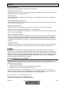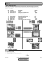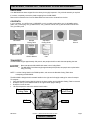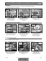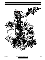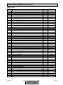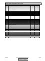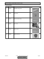
1
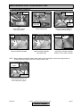
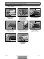
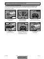
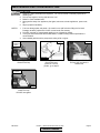
MK- 2005G
GAS POWERED BRICK SAW
OWNER’S MANUAL &
OPERATING INSTRUCTIONS
CAUTION:
Read all safety and
operating instructions
before using this
equipment
Enter the Serial Number of your new saw in the
space below. The Serial Number is located on the
left side of the blade guard.
SERIAL NUMBER:
NOTE:
For your (1) one year warranty to be effective,
complete the warranty card (including the Serial
Number and mail it in as soon as possible.
Table of Contents
INTRODUCTION
We at MK Diamond want to congratulate you on selecting the MK-2005G Brick Saw. We are certain that you
will be pleased with your purchase. MK Diamond takes pride in producing the finest products in the industry.
Operated correctly, your MK-2005G should provide you with years of quality service. In order to help you, we
have included this manual. This owners manual contains information necessary to operate and maintain your
MK-2005G safely and correctly. Please take a few minutes to familiarize yourself with the MK-2005G by
reading and reviewing this manual.
If you should have questions concerning your MK-2005G, please feel free to call our friendly customer service
department at: 800 421-5830
Regards,
MK Diamond
MK-2005G
Revision 1, Effective Date December 26, 2000
Table of Contents
Page 2
TABLE OF CONTENTS
Page
SAFETY:
Safety Messages
Damage Prevention Message
General Safety Precautions and Hazard Symbols
California Proposition 65 Message
Safety Label Locations
Brick Saw Specific Warnings
Product Specifications
4
4
4
6
7
7
8
UNPACKING, TRANSPORT, UNIVERSAL STAND and ASSEMBLY
Unpacking
Contents
Transport
Universal Stand
Assembly
9
9
9
10
11
SETUP, STARTUP, ADJUSTMENT, OPERATION and SHUTDOWN
Setup
Startup
Adjustment and Operation
Shutdown
Cleanup
15
18
19
25
25
MAINTENANCE AND TROUBLESHOOTING
Maintenance
Troubleshooting
27
44
EXPLODED VIEW AND PARTS LIST
Exploded View
Parts List
47
48
THEORY
Theory Of Diamond Blades
52
ACCESSORIES ORDERING and RETURN INSTRUCTIONS
Accessories
Ordering Information
Return Material Policy
Packaging Instructions
Authorized Service Centers
53
54
55
55
55
Manual Part No. 158320
MK-2005G
Revision No. 1
Revision 1, Effective Date December 26, 2000
Page 3
SAFETY
Read and follow all safety, operating and maintenance instructions. Failure to read and follow these
instructions could result in injury or death to you or others. Failure to read and follow these instructions could
also result in damage and/or reduced equipment life.
SAFETY MESSAGES:
Safety messages inform the user about potential hazards that could lead to injury, death and/or equipment
damage. Each safety message will be preceded by one of the following (3) three words that identify the
severity of the message.
Not following instructions WILL lead to DEATH or SERIOUS INJURY
Not following instructions COULD lead to DEATH or SERIOUS INJURY
Not following instructions CAN lead to injury
DAMAGE PREVENTION AND INFORMATION MESSAGES:
A Damage Prevention Message is to inform the user of important information and/or instructions that could
lead to equipment or other property damage if not followed. Information messages convey information that
pertains to the equipment being used. Each message will be preceded by the word note, as in the example
below.
NOTE: Equipment and/or property damage may result if these instructions are not followed.
GENERAL SAFETY PRECAUTIONS AND HAZARD SYMBOLS:
In order to prevent injury, the following safety precautions and symbols should be followed at all times!
Safety Precautions:
KEEP GUARDS IN PLACE.
In order to prevent injury, keep guards in place and in working order at all times.
EXPLOSIVE FUEL!
Gasoline is extremely flammable, its vapors can explode if ignited; store only in approved containers,
in well-ventilated, unoccupied buildings and away from sparks or flames. Do not fill the fuel tank while
the engine is running or hot. Spilled fuel could ignite if it contacts hot parts or sparks from ignition. Do
not start the engine near spilled fuel. Never use gasoline as a cleaning agent.
LETHAL EXHAUST GASES!
Engine exhaust gasses contain poisonous carbon monoxide, an odorless colorless gas that can cause
death if inhaled. Avoid inhaling exhaust fumes, and never run the engine in a closed building or
confined area.
ELECTRICAL SHOCK!
Never touch electrical wires or components while the motor is running. Exposed, frayed or worn
electrical motor wiring can be sources of electrical shock that could cause severe injury or burns.
ENGINE OVER-SPEED.
Never tamper with the governor components or settings to increase the maximum speed of the
machine. Severe personal injury and/or equipment damage could result if the equipment is operated
speeds above design maximum.
MK-2005G
Revision 1, Effective Date December 26, 2000
Table of Contents
Page 4
SAFETY
ACCIDENTAL STARTS!
Before starting the engine, be sure the ON/OFF switch is in the "OFF" position to prevent accidental
starting. Place the ON/OFF switch in the OFF position before performing any service operation.
ROTATING OR MOVING PARTS!
Keep hands, feet, hair, and clothing away from all moving parts to prevent injury. Never operate a
power tool with shrouds or guards removed.
HOT PARTS!
Engine components can become extremely hot from operation. To prevent severe burns, do not touch
these areas while the engine is running, or immediately after it is turned off. Never operate the engine
with heat shields removed.
ALWAYS USE SAFETY GLASSES!
Safety glasses should always be worn when working around power tools. Everyday eyeglasses only
have impact resistant lenses and may not prevent eye injury; they are NOT safety glasses.
ALWAYS USE RESPIRATORY PROTECTON!
Exhaust gases may be harmful if inhaled. Do not operate gas-powered equipment in enclosed
spaces. Respiratory protection should be worn when operating gas powered equipment.
ALWAYS USE HEARING PROTECTION!
To reduce the possibility of hearing loss, always use hearing protection when operating equipment.
REMOVE ADJUSTING KEYS AND WRENCHES.
Form a habit of checking to see that keys and adjusting wrenches are removed from the power tool before it
is turned on.
KEEP WORK AREA CLEAN.
Cluttered work areas and benches invite accidents.
DO NOT USE IN DANGEROUS ENVIRONMENTS.
Do not operate equipment in dangerous environments. Always keep the work area well lighted.
KEEP CHILDREN AWAY.
All visitors and children should be kept a safe distance from work area.
MAKE WORKSHOP KID PROOF.
Make the workshops kid proof by using padlocks, master switches or by removing starter keys.
DO NOT FORCE THE TOOL.
A power tool will do a job better and safer operating at the rate for which it was designed.
USE THE RIGHT TOOL.
Do not force a tool or an attachment, to do a job that it was not designed to do.
WEAR PROPER APPAREL.
Do not wear loose clothing, gloves, neckties, rings, bracelets, or other jewelry that may be caught in moving
parts. Nonslip footwear is recommended. Wear protective hair covering to contain long hair.
SECURE WORK.
Clamps or a vise should be used to hold work whenever practical. Keeping your hands free to operate a
power tool is safer.
MK-2005G
Revision 1, Effective Date December 26, 2000
Table of Contents
Page 5
SAFETY
DO NOT OVERREACH.
Keep proper footing and balance at all times by not overreaching.
MAINTAIN TOOLS WITH CARE.
Keep tools sharp and clean for the best and safest performance. Always follow maintenance instructions for
lubricating and when changing accessories.
SHUTDOWN TOOL.
The saw should always be shutdown before servicing or when changing accessories such as blades, bits,
cutters, and the like.
USE RECOMMENDED ACCESSORIES.
Consult the owner's manual for recommended accessories. Using improper accessories may increase the
risk of personal or by-stander injury.
NEVER STAND ON THE TOOL.
Serious injury could occur if a power tool is tipped, or if a cutting tool is unintentionally contacted.
NEVER LEAVE TOOL RUNNING UNATTENDED – TURN POWER OFF.
Do not leave a tool until it comes to a complete stop. Always turn a power tool OFF when leaving the work
area, or, when a cut is finished.
CHECK FOR DAMAGED PARTS.
Before using a power tool, check for damaged parts. A guard or any other part that is damaged should be
carefully checked to determine it would operate properly and perform its intended function. Always check
moving parts for proper alignment or binding. Check for broken parts, mountings and all other conditions
that may affect the operation of the power tool. A guard or any damaged part should be properly repaired or
replaced.
DIRECTION OF FEED.
Always feed work into a blade or cutter against the direction of rotation. A blade or cutter should always be
installed such that rotation is in the direction of the arrow imprinted on the side of the blade or cutter.
Sawing and drilling generates dust. Excessive airborne particles may cause irritation to eyes, skin and
respiratory tract. To avoid breathing impairment, always employ dust controls and protection suitable to the
material being sawed or drilled; See OSHA (29 CFR Part 1910.1200). Diamond Blades improperly used are
dangerous. Comply with American National Standards Institute Safety Code, B7.1 and, Occupational Safety
and Health Act covering Speed, Safety Guards, Flanges, Mounting Procedures, General Operating Rules,
Handling, Storage and General Machine Conditions.
CALIFORNIA PROPOSITION 65 MESSAGE:
Some dust created by power sanding, sawing, grinding, drilling, and other construction activities contain
chemicals known [to the State of California] to cause cancer, birth defects or other reproductive harm. Some
examples of these chemicals are:
• Lead, from lead-based paints
• Crystalline silica, from bricks and cement and other masonry products
• Arsenic and chromium, from chemically treated lumber
Your risk from these exposures varies depending on how often you do this type of work. To reduce your
exposure to these chemicals, work in a well-ventilated area, and work with approved safety equipment, such
as those dust masks that are specially designed to filter out microscopic particles.
For further information, consult the following sources:
http://www.osha-slc.gov/sltc/silicarystalline/index.html
http://www.oehha.org/prop65/out_of_date/6022kLstA.html
MK-2005G
Revision 1, Effective Date December 26, 2000
Table of Contents
Page 6
SAFETY
SAFETY LABEL LOCATIONS:
Safety labels are located according to Figures 1 through 6 below. The labels contain important safety
information. Please read the information contained on each safety label. These labels are considered a
permanent part of your saw. If a label comes off or becomes hard to read, contact MK Diamond or your
dealer for a replacement.
Item
1A
1B
2A
2B
2C
3
4
5
6A
6B
Location
Motor-tank, front
Motor-tank, front
Motor-tank, top
Motor-tank, top
Motor-tank, top
Motor-tank, right
Motor-tank, left
Motor-air filter
Blade Guard
Blade Guard
Description
Oil Alert
Danger-Use in Ventilated Areas
Warning-Do Not Overfill
Caution-Hot Surface
Honda Motor Information
Danger-California Exhaust Warning
Read Honda Owner's Manual
Caution-Clean Air Filter
Serial Number
Caution-Operating Safety Instructions
A
Part No.
N/A
155582
155580
155578
N/A
155581
N/A
N/A
157007
155040
A
B
B
C
1
2
3
4
B
A
5
6
Brick Saw SPECIFIC WARNINGS:
•
•
•
Read Owner's Manual
Keep All Guards In Place
Always Wear Approved Safety Protection For:
MK-2005G
Ø
Ø
Ø
Ear
Eye
Head
Revision 1, Effective Date December 26, 2000
Table of Contents
Page 7
SAFETY
PRODUCT SPECIFICATIONS:
The MK-2005G is a versatile gas powered brick saw. Operated and used according to this manual, the MK2005G will provide years of dependable service.
General Description:
The MK-2005G Brick Saw is engineered as a portable brick saw powered by a 5.5 horsepower, pull start,
Honda gas engine. The saw is capable of cutting masonry up to five (5) inches (127 mm) in height in a single
pass.
Motor Specifications:
Honda motor specifications for the MK-2005G are listed in Table 1 below.
Motor Type
Max Power Output
Max RPM
Fuel Tank Capacity
Engine Oil Capacity
4-stroke, overhead valve, single cylinder
5.5 Hp
3,600 RPM
0.95 gallons (3.6 liters)
0.63 quarts (0.6 liters)
Table 1
Blade Capacity:
The MK-2005G is designed for use with a 14-inch diameter segmented wet or dry MK Diamond blade with a
.110 to .375 inch cutting width.
Masonry Types:
The MK-2005G can cut a variety of masonry types including, cinder block, slump stone block, wall brick,
paver brick, concrete block and cylinders, roofing tile, marble, granite, decorative rock or almost any other
non-ferrous material.
NOTE:
The MK-2005G is not designed to cut plastic or ferrous (metals) material.
Spring Assisted Cutting Head:
The MK-2005G is designed with a spring-assisted cutting head to allow for easier step cutting. The Cutting
Head can be locked in the down position when cutting smaller pieces.
Shaft Operated Water Pump:
The MK-2005G has a flexible shaft, belt driven water pump supplying cooling water to the blade for wet
cutting operations.
Design Size:
The MK-2005G is designed to accommodate a piece up to eighteen and one-half (18-1/2) inches (470 mm)
wide, thirty (30) inches (760mm) long and seven and one-half (7-1/2) inches high.
MK-2005G
Revision 1, Effective Date December 26, 2000
Table of Contents
Page 8
UNPACKING, TRANSPORT, UNIVERSAL STAND and ASSEMBLY
UNPACKING:
Your MK-2005G has been shipped from the factory thoroughly inspected. Only minimal assembly is required.
If not done, completely remove the plastic wrapping from the MK-2005G.
Remove the accessories box from the Water Basin and remove the contents from the box.
CONTENTS:
In your container, you will find one (1) MK-2005G, one (1) movable cutting table, one (1) adjustable cutting
guide, one (1) drain plug, one (1) blade wrench, one (1) owner's manual, one (1) Honda owner's manual and
one (1) warranty card.
MK-2005G
Movable
Cutting Table
Adjustable
Cutting Guide
Owner's Manual
Honda
Owner's Manual
Warranty
Card
Drain Plug
Blade
Wrench
TRANSPORT:
The MK-2005G weighs approximately 200 pounds; two people should be used when transporting the saw.
1.
2.
Never transport the MK-2005G with water in the Cooling Basin.
The MK-2005G, Brick Saw weighs approximately 200 pounds; two people are required when
lifting or moving.
NOTE: Lock the Cutting Head in the DOWN position, and remove the Movable Cutting Table when
transporting the MK-2005G.
The MK-2005G is designed with recessed handles in the right and left upright castings for ease of transport.
To transport –
• Verify the Movable Cutting Head is locked in the down position and the Movable Cutting Table is removed
• Grasp the saw by the recessed handle in the right and left upright castings
• Grasp the front of the saw
• Lift and transport the saw to the desired work location
Cutting Head
Locked Down
Remove Movable
Cutting Table
Lift Point
MK-2005G
Lift Point
Revision 1, Effective Date December 26, 2000
Table of Contents
Page 9
UNPACKING, TRANSPORT, UNIVERSAL STAND and ASSEMBLY
UNIVERSAL STAND:
Note: If using the MK Diamond, Universal Stand, perform the following steps.
1. Preparing to Seat Saw:
The MK-2000, Brick Saw weighs approximately 200 pounds; two people are required when lifting
or moving.
Loosen Wing Nut
Slide Water Basin
out back of Saw
Pivot Up
(A)
Open the Universal Stand
and place on flat surface
(B)
Position Water Pump
clear of Water Basin
(C)
Remove Water Basin
2. Seating the Saw:
Front Brace
Back of Saw
Back of Stand
(A)
Orient the Saw
to the Stand
Rear of Saw
Front of Stand
(B)
Seat front of Saw
on the front of the Stand
Back of Stand
(C)
Seat rear of Saw
on the back of the Stand
3. Final:
Slide Water Basin
in back of Saw
(C)
Reinstall Water Basin
MK-2005G
Revision 1, Effective Date December 26, 2000
Table of Contents
Page 10
UNPACKING, TRANSPORT, UNIVERSAL STAND and ASSEMBLY
ASSEMBLY:
Follow the assembly instructions in this section to prepare your MK-2005G for operation.
1. Movable Cutting Table Installation:
Cutting Table
Front
Roller Wheels
Guide Rail
(A)
Position Movable Cutting
Table Roller Wheels
above Saw Guide Rails
Roller Wheels
Guide Rails
(B)
Seat Movable Cutting Table
Roller Wheels on Saw
Guide Rails
Move back and forth to
verify ease of movement
(C)
Verify Movable Cutting Table
is seated correctly
2. Adjustable Cutting Guide Installation:
NOTE: The Adjustable Cutting Guide can be used on either side of the Diamond Blade.
Turn counterclockwise to loosen
Align
Parallel Slots
Turn clockwise
to tighten
Ruler/Stop
(A)
Loosen Adjustable Cutting
Guide retaining thumbscrew
(B)
Position Adjustable Cutting
Guide above Movable
Cutting Table
Seated
(C)
Seat and tighten the
Adjustable Cutting Guide
retaining thumbscrew
3. Releasing Cutting Head:
The following actions will cause the Cutting Head to rotate upward, hold the saw by the handle and
control the upward movement.
NOTE: The Cutting Head is locked in the down position when shipped from the factory.
Turn counterclockwise to
loosen
Locking Handle
9/16-inch wrench
(A)
Remove Cutting Head Locking
Handle from shipping location
discard the Shipping Nut
MK-2005G
9/16-inch
wrench
Shipping Bolt
(B)
Remove Shipping Bolt from
the Cutting Head – discard
Shipping Bolt
Revision 1, Effective Date December 26, 2000
Table of Contents
Turn clockwise
to tighten
Height
Adjustment
Stud
Locking Handle
(C)
Install Cutting Head
Locking Handle into
Height Adjustment Stud
Page 11
UNPACKING, TRANSPORT, UNIVERSAL STAND and ASSEMBLY
4. Diamond Blade Installation:
NOTE: When installing the diamond blade retaining-bolt, ensure the threads of the bolt are aligned with the
threads of the drive shaft so as not to “cross-thread" the bolt.
Cutting Head
Blade Wrench
Loosen Locking
Handle to adjust
Cutting Head
Retaining Screw
and Outer Flange
Install
Blade
Turn counterclockwise to
loosen
(A)
Raise Cutting Head
(B)
Identify and remove Retaining
Screw and Outer Flange
(C)
Install Diamond Blade
onto Blade Shaft
Rotate Blade
Wrench clockwise
to tighten
Seat Blade on
Blade Shaft
Retaining Screw
and Outer Flange
Rotation Direction
(D)
Verify Blade is seated on Blade
Shaft in correct rotation direction
(E)
Install Retaining Screw and
Outer Flange then tighten
5. Water Pump Installation:
NOTE: The Belt Driven, Flexible Shaft Water Pump is locked in the shipping position from the factory. It will
need to be removed from between the left Upright Casting and the Cutting Head to allow free movement of
the Cutting Head.
Loosen Wing Nut
7/16-inch
Wrench
Remove Water Pump
(A)
Loosen and remove Water
Pump adjustment clamp,
wing nut and bolt
MK-2005G
Remove Water
Pump from Clamp
Cutting
Head
Loosen Wing Nut
Water
Pump
(B)
Loosen and remove Water
Pump retaining clamp,
wing nut and bolt
Revision 1, Effective Date December 26, 2000
Table of Contents
Upright
Casting
(C)
Remove Water Pump Assembly
from between left Upright
Casting and Cutting Head
Page 12
UNPACKING, TRANSPORT, UNIVERSAL STAND and ASSEMBLY
7/16-inch
Wrench
Install Water
Pump into Clamp
Tighten Wing Nut
Install Water Pump
Tighten Wing Nut
(D)
Install Water Pump retaining
clamp, wing nut and bolt
(E)
Install Water Pump adjustment
clamp. wing nut and bolt
6. Filling Oil Reservoir:
NOTE:
SAE 10W-30 is recommended for general use in temperatures of – 4ºF (20ºC) and above. If you
are operating outside of this range, consult the chart in this manual.
Engine Oil Capacity is 0.63 US qt (0.6l).
Cutting Head
Turn counterclockwise to
loosen
Loosen Locking
Handle to adjust
Cutting Head
(A)
Level Cutting Head
Dipstick
(B)
Remove Dipstick
Fill through
Reservoir fill hole
(C)
Fill Oil Reservoir
NOTE: When installing the Oil Dipstick, ensure the threads are aligned with the threads of the Oil Reservoir
so as not to “cross-thread" the dipstick.
Bottom Edge
Turn clockwise
to tighten
Wipe up excess oil
Dipstick
(D)
Add Oil until level reaches
the bottom edge of fill hole
MK-2005G
(E)
Install Dipstick
Revision 1, Effective Date December 26, 2000
Table of Contents
(F)
Clean Up
Page 13
UNPACKING, TRANSPORT, UNIVERSAL STAND and ASSEMBLY
7. Filling Fuel Tank:
1. Gasoline is highly flammable and explosive. You can be burned or seriously injured when
handling fuel.
2. To fuel, stop engine if running, and allow it to cool.
3. Refuel in a well-ventilated area.
4. Keep gasoline away from appliance pilot lights, barbecues, electric appliances, power tools,
etc.
5. Wipe up spills immediately.
NOTES:
1. Fuel can damage paint and plastic. Be careful not to spill fuel when filling the fuel tank.
Damage caused by spilled fuel IS NOT covered under the warranty.
2. DO NOT use stale or contaminated gasoline, or an oil/gasoline mixture.
3. If using the Universal Stand with the MK-2005G, a ladder meeting OSHA specification is
recommended.
4. Use unleaded gasoline with a pump octane rating of 86 or higher.
Turn counterclockwise to
loosen
Fill Throat
Fuel Cap
(A)
Remove Fuel Cap
Fill Throat
Upper Limit
(B)
Fill Fuel Tank
(C)
Verify fuel level is below
the throat of the Fuel Tank
Turn clockwise
to tighten
Fuel Cap
(D)
Install Fuel Cap
MK-2005G
Revision 1, Effective Date December 26, 2000
Table of Contents
Page 14
SETUP, STARTUP, ADJUSTMENT, OPERATION and SHUTDOWN
SETUP:
1. Pre-start Inspection:
The pre-start inspection should be performed before beginning any job.
If the Diamond Blade shows signs of fatigue cracking, replace the blade before starting work.
Cracks
Verify Ease of Movement
(See Maintenance Section)
Replace if Excessively Grooved
(See Maintenance Section)
(A)
Inspect Blade for damage –
Verify Blade correct for material
being cut
(B)
Inspect Wooden Strip for
excessive grooves
Inspect for
damage
Look for leaks
(D)
Inspect Engine for leaks
Fill Throat
(C)
Verify Movable Cutting Table
moves freely
Proper Oil Level
Low Level
(E)
Inspect MK-2005G for general
damage, loose connections
and hardware
(F)
Check for proper oil level
(See Maintenance section if low)
Air Filter
Upper Limit
(G)
Check for proper fuel level
(See Maintenance section if low)
MK-2005G
(H)
Check Air Filter for cleanliness
(See Maintenance section
if dirty)
Revision 1, Effective Date December 26, 2000
Table of Contents
Page 15
SETUP, STARTUP, ADJUSTMENT, OPERATION and SHUTDOWN
2. Water Pump Setup:
The Water Pump can be setup in three ways, External Water Source, Re-circulation or Un-coupled for dry
blade operation.
NOTE: To extend the life of the Diamond Blade and Water Pump, MK Diamond recommends a clean cooling
water source when using a Wet Diamond Blade.
I. External Water Source:
This is the preferred method of cooling when using a "wet" diamond blade.
Drain Plug
Water Basin
Loosen Wing Nut
Remove Water Pump
(A)
Verify Water Basin is inserted
into the MK-2005G and
remove the Drain Plug
(B)
Loosen and remove Water
Pump adjustment clamp,
wing nut and bolt
Water Pump
Water Container
(C)
Place the Water Pump
Assembly into an External
Water Source Container
Clean Water
(D)
Fill the External Water Source
Container and place a Catch
Basin below the Drain Hole
II. Re-circulation:
NOTE: 1. Water Pump could interfere with masonry being cut.
2. Water should be periodically replaced when using this method.
Drain Plug
Water Basin
Loosen Wing Nut
Water Pump
Molded Stand
(A)
Verify Water Basin is inserted
into the MK-2005G and
install the Drain Plug
MK-2005G
(B)
Loosen Water Pump adjustment
clamp wing nut and bolt
Revision 1, Effective Date December 26, 2000
Table of Contents
(C)
Place Water Pump on Pump
Stand molded into Water Basin
Page 16
SETUP, STARTUP, ADJUSTMENT, OPERATION and SHUTDOWN
Clean Water
(D)
Fill the Water Basin
with clean water
III. Dry Blade Operation:
NOTE: Failure to perform the following steps will lead to premature pump failure.
Pivot Plate
9/16-inch
Wrench
Retaining Bolts
(A)
Identify Water Pump Drive
End Pivot Plate
Splash Curtain
Curtain Rod
(B)
Loosen Water Pump Drive End
Pivot Plate front and rear
retaining bolts
9/16-inch
Wrench
(C)
Pivot front of Water Pump Drive
End Pivot Plate up and tighten
the retaining bolts
Loosen Wing Nut
Remove Water Pump
(D)
Remove the Splash Curtain
Pivot Up
(E)
Loosen and remove Water
Pump adjustment clamp,
wing nut and bolt
Water Pump
(F)
Move Water Pump Assembly
to the outside of the
Water Basin
Slide Water Basin
out back Of Saw
(G)
Remove Water Basin
MK-2005G
Revision 1, Effective Date December 26, 2000
Table of Contents
Page 17
SETUP, STARTUP, ADJUSTMENT, OPERATION and SHUTDOWN
STARTUP:
1. Engine Start:
1. Carbon monoxide gas is toxic. Breathing it can cause unconsciousness and/or death.
2. Avoid any areas or actions that expose you to carbon monoxide.
NOTE:
If restarting a warm engine leave the Choke Lever in the OPEN position.
Direction of
Movement
Fuel Valve
Direction of
Movement
Direction of
Movement
Throttle Lever
Choke Lever
(A)
Place Fuel Valve in the
ON position
Engine Switch
(B)
Place Choke Lever in the
CLOSED position
Starter Cord
Direction of
Movement
Direction of
Movement
(D)
Place Engine Switch
in the ON position
(C)
Move the Throttle Lever
rd
to 1/3 Open
(E)
Pull Starter Cord slowly, until
slack is removed and
resistance is felt
Starter Cord
Direction of
Movement
(F)
Pull Starter Cord straight back
in a smooth fast motion
Direction of
Movement
Choke Lever
(G)
Place Choke Lever in the OPEN
position when engine is warm
MK-2005G
Revision 1, Effective Date December 26, 2000
Table of Contents
Page 18
SETUP, STARTUP, ADJUSTMENT, OPERATION and SHUTDOWN
ADJUSTMENT AND OPERATION:
NOTE:
1.
2.
3.
Step Cutting is the preferred cutting method for all cuts.
When cutting hard material Step Cutting should always be used.
Step Cutting will extend the life of the Diamond Blade.
1. Step Cuts:
A Step Cut is performed when a series of small cuts of increasing depth are used to complete a single cut.
Step Cuts are used for large objects or for hard objects such as Firebrick and Pavers.
DO NOT FORCE TOOL, it will do the job better and safer at the rate for which it was designed.
Note:
Skip steps C and D, if cutting dry.
Set Edge of Cutting
Guide to Desired Cut
Length on Ruler/Stop
Ruler Markings
Adjustable
Cutting Guide
Ruler/Stop
Ruler/Stop
(A)
Set the Adjustable Cutting Guide
Set against Adjustable
Cutting Guide and
Ruler/Stop
(B)
Position the masonry piece
Direction of
Movement
Control Valve
(C)
Open the Cooling Flow Control
Valve and adjust flow
Direction of
Movement
Cooling Flow
Points
(D)
Verify cooling flow exists on
both sides of the blade
Lower Cutting
Head 1/4 -1/2
Inch During
Push Stroke
Push Direction
(G)
Step Cut "Push" stroke
MK-2005G
Hold Work
in Position
Throttle Lever
(E)
Move the Throttle Lever to
adjust blade speed (faster blade
speed for smoother cuts)
(F)
Setup to Cut
Lower Cutting
Head Additional
1/4 -1/2 Inch During
Pull Stroke
Pull Direction
(H)
Step Cut "Pull" stroke
Revision 1, Effective Date December 26, 2000
Table of Contents
Repeat “Push”
and “Pull” Strokes
Until Cut Complete
(I)
Repeat steps G and H until
cutting is complete
Page 19
SETUP, STARTUP, ADJUSTMENT, OPERATION and SHUTDOWN
Direction of
Movement
Raise Cutting
Head
Throttle Lever
(K)
Move the Throttle Lever to lower
blade speed
(J)
Raise Cutting Head once
cut is complete
2. Chop Cutting:
A Chop Cut is performed by cutting completely through an object in one pass.
DO NOT FORCE TOOL, it will do the job better and safer at the rate for which it was designed.
Note:
Skip steps C and D, if cutting dry.
Set Edge of Cutting
Guide to Desired Cut
Length on Ruler/Stop
Ruler Markings
Adjustable
Cutting Guide
Ruler/Stop
(A)
Set the Adjustable Cutting Guide
Set against Adjustable
Cutting Guide and
Ruler/Stop
Ruler/Stop
(B)
Position the masonry piece
Direction of
Movement
Control Valve
(C)
Open the Cooling Flow Control
Valve and adjust flow
Direction of
Movement
Cooling Flow
Points
(D)
Verify cooling flow exists on
both sides of the blade
MK-2005G
Throttle Lever
(E)
Move the Throttle Lever to
adjust blade speed (faster blade
speed for smoother cuts)
Revision 1, Effective Date December 26, 2000
Table of Contents
Position
Work Below
Cutting Head
(F)
Setup to Cut
Page 20
SETUP, STARTUP, ADJUSTMENT, OPERATION and SHUTDOWN
Hold Cutting
Table Stationery
Lower Cutting
Head Smoothly
to Cut
Continue to Lower
Cutting Head until
Cut Complete
Direction of
Movement
Throttle Lever
(G)
Lower Cutting Head
to begin the cut
(H)
Continue lowering the
Cutting Head until the
cut is complete
(J)
Move the Throttle Lever to lower
blade speed
Raise Cutting
Head
(J)
Raise Cutting Head once
cut is complete
3. Cutting with the Cutting Head Locked Down:
This method is preferred when cutting small objects.
DO NOT FORCE TOOL, it will do the job better and safer at the rate for which it was designed.
Note:
Skip steps D and E, if cutting dry.
Set Edge of Cutting
Guide to Desired Cut
Length on Ruler/Stop
Ruler Markings
Ruler/Stop
(A)
Set the Adjustable Cutting Guide
MK-2005G
Adjustable
Cutting Guide
Set against Adjustable
Cutting Guide and
Ruler/Stop
Ruler/Stop
(B)
Position the masonry piece
Revision 1, Effective Date December 26, 2000
Table of Contents
Loosen Locking
Handle to adjust
Cutting Head
Lock Cutting
Head in down
position
(C)
Lock Cutting Head in
the down position
Page 21
SETUP, STARTUP, ADJUSTMENT, OPERATION and SHUTDOWN
Direction of
Movement
Direction of
Movement
Control Valve
(D)
Open the Cooling Flow Control
Valve and adjust flow
Cooling Flow
Points
Throttle Lever
(E)
Verify cooling flow exists on
both sides of the blade
(F)
Move the Throttle Lever to
adjust blade speed (faster blade
speed for smoother cuts)
Direction of
Movement
Hold Work
in Position
(G)
Setup to Cut
Throttle Lever
Push Slowly to Cut
(H)
Slowly push piece toward the
blade – continue until the
cut Is complete
(I)
Move the Throttle Lever to lower
blade speed
Loosen Locking
Handle to adjust
Cutting Head
Unlock Cutting
Head
(J)
Unlock Cutting Head
MK-2005G
Raise Cutting
Head
(K)
Raise Cutting Head once
cut is complete
Revision 1, Effective Date December 26, 2000
Table of Contents
Page 22
SETUP, STARTUP, ADJUSTMENT, OPERATION and SHUTDOWN
4. Angle Cuts:
Angle Cuts may be performed using the Step Cut, Chop Cut or the Locked Cutting Head cutting methods.
The following is utilizing the Locked Cutting Head method.
DO NOT FORCE TOOL, it will do the job better and safer at the rate for which it was designed.
NOTE: Care must be used when cutting angles so as not to damage the Adjustable Cutting Guide.
Skip steps F and G, if cutting dry.
Turn counterclockwise
to loosen
Align 45° Slots
to Ruler/Stop
Remove Adjustable
Cutting Guide
Adjustable
Cutting Guide
Place Work
in Position
Ruler/Stop
(A)
Remove Adjustable
Cutting Guide
Loosen Locking
Handle to adjust
Cutting Head
(B)
Reposition Adjustable
Cutting Guide
Turn clockwise
to tighten
Lock Cutting
Head in down
position
(D)
Lock Cutting Head in
the down position
(C)
Position masonry piece
against the Adjustable
Cutting Guide
Direction of
Movement
Align work
with Blade
(E)
Position Adjustable Cutting
Guide and masonry piece to
required cut position
Control Valve
(F)
Open the Cooling Flow Control
Valve and adjust flow
Direction of
Movement
Cooling Flow
Points
(G)
Verify cooling flow exists on
both sides of the blade
MK-2005G
Hold Work
in Position
Throttle Lever
(H)
Move the Throttle Lever to
adjust blade speed (faster blade
speed for smoother cuts)
Revision 1, Effective Date December 26, 2000
Table of Contents
(I)
Setup to Cut
Page 23
SETUP, STARTUP, ADJUSTMENT, OPERATION and SHUTDOWN
Loosen Locking
Handle to adjust
Cutting Head
Direction of
Movement
Push Slowly to Cut
Throttle Lever
(J)
Slowly push piece toward the
blade – continue until the
cut Is complete
(K)
Move the Throttle Lever to
lower blade speed
Unlock Cutting
Head
(L)
Unlock Cutting Head
Raise Cutting
Head
(M)
Raise Cutting Head once
cut is complete
MK-2005G
Revision 1, Effective Date December 26, 2000
Table of Contents
Page 24
SETUP, STARTUP, ADJUSTMENT, OPERATION and SHUTDOWN
SHUTDOWN:
1. Normal Engine Shutdown:
Direction of
Movement
Engine Switch
Direction of
Movement
Direction of
Movement
Fuel Valve
Throttle Lever
(A)
Move the Throttle Lever to lower
blade speed
(B)
Place Engine Switch
in the OFF position
(C)
Place Fuel Valve in the
OFF position
2. Emergency Engine Shutdown:
Engine Switch
Direction of
Movement
Direction of
Movement
Direction of
Movement
Fuel Valve
Throttle Lever
(A)
Place Engine Switch
in the OFF position
(B)
Move the Throttle Lever to lower
blade speed
(C)
Place Fuel Valve in the
OFF position
3. Cleanup:
Engine parts are extremely hot following use, allow engine to cool 1/2-hour before cleaning. Use
care during cleanup to avoid injury.
NOTE: If a clean external water source was used, steps A to C may be skipped.
Pump Suction
Water Pump
Water Container
(A)
Clean Water Pump
suction of all debris
MK-2005G
(B)
Place Water Pump in a
container of clean water
Revision 1, Effective Date December 26, 2000
Table of Contents
Cooling Flow
Points
(C)
Run MK-2005G until clear water
is seen at blade cooling ports
(Approx. 1 minute)
Page 25
SETUP, STARTUP, ADJUSTMENT, OPERATION and SHUTDOWN
Engine Switch
Direction of
Movement
(D)
Place Engine Switch
in the OFF position
NOTE:
Drain Plug
Clean Water Basin
(E)
Remove Drain Plug and dispose
of water (conform to Federal,
State and local laws for disposal)
(F)
Clean Water Basin with soap
and clean water
1. To extend operating life, the MK-2005G should be cleaned following every use.
2. Using a garden hose or pressure washer can force water into the air cleaner or muffler opening.
3. Use care when cleaning around electrical components.
Guide Rail
Clean Exterior
Roller Wheel
(G)
Clean Movable Cutting Table
Guide Rails with soap and
clean water
(H)
Clean Movable Cutting Table
Roller Wheels
(I)
Clean exterior surface of
MK-2005G (except engine)
with soap and clean water
Air Filter
Mounting Plates
(J)
Clean between engine
mounting plates
MK-2005G
Throttle Linkage
(K)
Clean Air Filter
(See Maintenance section)
Revision 1, Effective Date December 26, 2000
Table of Contents
(L)
Clean engine throttle linkage
with a dry cloth
Page 26
MAINTENANCE AND TROUBLESHOOTING
MAINTENANCE:
1. New Maintenance:
Perform the following after initial purchase and operation of the MK-2005G.
Inspect V-Belts
Change Oil
(A)
st
Change engine oil after 1
st
month or 1 20 operating hours
(See Engine Oil Change)
(B)
Check and adjust V-belt tension
st
Following 1 48 hours of operation
See V-belt Inspection
2. Maintenance Following Use:
To extend the life of the MK-2005G, the following procedure should be performed after each use. Lubricate
all points listed below with light oil such as, 3 in 1, WD-40, etc.
Engine Switch
Direction of
Movement
Lubricate Roller Wheels
Torsion Spring
(A)
Place Engine Switch
in the OFF position
(B)
Lubricate the Movable Cutting
Table Roller Wheels
(C)
Lubricate Torsion Spring
Pivot Point
Adjustment Bar
(D)
Lubricate Blade Guard Pivot
Points and Adjustment Bar
MK-2005G
Throttle Linkage
(E)
Lubricate engine throttle linkage
Revision 1, Effective Date December 26, 2000
Table of Contents
Page 27
MAINTENANCE AND TROUBLESHOOTING
3. Monthly Maintenance:
The following should be performed monthly. Items should be lubricated as directed.
Outer Flange
1/2-inch
Wrench
1/2-inch
Wrench
Retaining
Bolt
9/16-inch
Wrench
(A)
Remove and clean Diamond
Blade Outer Flange and
Retaining Bolt
(B)
Verify all engine mounting
bolts are tight
(C)
Verify engine Adjustment
Straps are tight
Air Filter
Roller Wheels
(D)
Check Movable Cutting Table
Roller Wheels for wear
(E)
Clean engine Air Filter
(See Engine Air Filter Inspection
Cleaning and Replacement)
4. Six (6) Month Maintenance:
Perform the following maintenance every six months.
Fuel Sediment Cup
Spark Plug
Change Oil
(A)
Change engine oil
(See Engine Oil Change)
MK-2005G
(B)
Clean Fuel Sediment Cup
(See Fuel Sediment
Cup Cleaning)
Revision 1, Effective Date December 26, 2000
Table of Contents
(C)
Clean and Readjust engine
Spark Plug (See Spark Plug
Adjustment and Replacement)
Page 28
MAINTENANCE AND TROUBLESHOOTING
5. Yearly Maintenance:
Perform the following maintenance every year.
Air Filter
(A)
Replace engine Air Filter
(See Engine Air Filter Inspection
Cleaning and Replacement)
Spark Plug
(B)
Replace Spark Plug
(See Spark Plug
Adjustment and Replacement)
(C)
Check/Adjust Idle Speed
Check/Adjust Valve Clearance
(Shop Maintenance Required)
Inspect V-Belts
(D)
Inspect V-belts
(See V-Belt Inspection,
Adjustment and Replacement)
6. Two Year Maintenance:
(A)
Check Fuel Line
(Shop Maintenance Required)
MK-2005G
Revision 1, Effective Date December 26, 2000
Table of Contents
Page 29
MAINTENANCE AND TROUBLESHOOTING
7. Blade Dressing:
Like most cutting instruments, a diamond blade performs best when it is dressed. Over time and use,
diamonds on the outer edge will become smoothed or “glazed” over. This will reduce grinding efficiency and
may cause the blade to “wander” or bend giving the illusion of an alignment problem. When this occurs, the
blade will need to be dressed. The diamond blade can be dressed using the MK Dressing Stick (part number
152792) and by following the steps below.
NOTE:
Skip Steps D and E if cutting dry.
Set Edge of Cutting
Guide to desired Cut
Length on Ruler/Stop
Ruler Markings
(A)
Setup MK-2005G for operation
(See Setup, Startup, Adjustment
Operation and Shutdown)
Set against Adjustable
Cutting Guide and
Ruler/Stop
Ruler/Stop
Ruler/Stop
(B)
Set the Adjustable Cutting Guide
to cut 1/16-inch strips
Adjustable
Cutting Guide
(C)
Position the Dressing Stick
Direction of
Movement
Direction of
Movement
Control Valve
(D)
Open the Cooling Flow Control
Valve and adjust flow
Cooling Flow
Points
Throttle Lever
(E)
Verify cooling flow exists on
both sides of the blade
(E)
Move the Throttle Lever to
adjust blade speed (faster blade
speed for smoother cuts)
Direction of
Movement
Push Slowly to Cut
(F)
Cut the Dressing Stick 7 or 8
times to dress the Blade
MK-2005G
Throttle Lever
(G)
Move the Throttle Lever to lower
blade speed
Revision 1, Effective Date December 26, 2000
Table of Contents
Raise Cutting
Head
(H)
Raise Cutting Head once
cut is complete
Page 30
MAINTENANCE AND TROUBLESHOOTING
8. Diamond Blade Change-out:
Engine Switch
Direction of
Movement
Cutting Head
Blade Wrench
Loosen Locking
Handle to adjust
Cutting Head
(A)
Place Engine Switch
in the OFF position
Remove
Blade
(B)
Raise Cutting Head
Install
Blade
Retaining Screw
and Outer Flange
Turn counterclockwise to
loosen
(C)
Identify and remove Retaining
Screw and Outer Flange
Seat Blade on
Blade Shaft
Rotation Direction
(D)
Remove old Diamond Blade
(E)
Install new Diamond Blade
onto Blade Shaft
(F)
Verify Blade is seated on Blade
Shaft in correct rotation direction
NOTE: When installing the diamond blade retaining-bolt, ensure the threads of the bolt are aligned with the
threads of the drive shaft so as not to “cross-thread" the bolt.
Rotate Blade
Wrench clockwise
to tighten
Retaining Screw
and Outer Flange
(G)
Install Retaining Screw and
Outer Flange then tighten
MK-2005G
Revision 1, Effective Date December 26, 2000
Table of Contents
Page 31
MAINTENANCE AND TROUBLESHOOTING
9. Movable Cutting Table Wheel Change Out:
NOTE: All four (4) Movable Cutting Table, Roller Wheels should be replaced at the same time (MK Diamond
Part No. – 133090)
Rotate Wrench
Counter-clockwise
Movable
Cutting Table
(A)
Remove the Movable
Cutting Table
1/2-Inch Wrench
Roller Wheels
(B)
Place Movable Cutting
Table On Work Bench
with Roller Wheels Up
(C)
Remove Roller Wheels
Washer
Clean Holes
(D)
Prepare for Installation
Of New Roller Wheels
Lubricate with
Light Oil (WD-40,
3 in 1, etc)
(F)
Lubricate Roller Wheels
MK-2005G
Rotate Wrench
Counter-clockwise
Roller Wheel
(E)
Install Wheel/Washer Assembly
Into Movable Cutting Table
1/2-Inch Wrench
(G)
Install Roller Wheel
Retaining Nut – Tighten
Movable
Cutting Table
(H)
Install the Movable
Cutting Table
Revision 1, Effective Date December 26, 2000
Table of Contents
Page 32
MAINTENANCE AND TROUBLESHOOTING
10. Protective Wooden Strip Replacement:
The protective wooden strip is to protect the Movable Cutting Table from damage during operation. Over
time, the wooden strip will become grooved from use. A grooved wooden strip will not support masonry
during cutting causing the blade to "break through" the piece instead of performing a smooth cut (MK
Diamond Part No. – 156427).
Phillips
Screwdriver
Movable
Cutting Table
(A)
Remove the Movable
Cutting Table
Worn Wooden
Strip
New Wooden
Strip
(D)
Replace Worn
Protective Wooden Strip
MK-2005G
Roller Wheels
Retaining Screw
(B)
Place Movable Cutting
Table On Work Bench
with Roller Wheels Up
(C)
Remove the two Protective
Wooden Strip Retaining Screws
Phillips
Screwdriver
Retaining Screw
(F)
Place Movable Cutting Table on
Work Bench – Wheels Up,
Reinstall Retaining Screws
Revision 1, Effective Date December 26, 2000
Table of Contents
Movable
Cutting Table
(G)
Install the Movable
Cutting Table
Page 33
MAINTENANCE AND TROUBLESHOOTING
11. Check Fuel Level:
1.
2.
3.
4.
5.
NOTES:
Gasoline is highly flammable and explosive. You can be burned or seriously injured when
handling fuel.
To fuel, stop engine if running and allow it to cool.
Refuel in a well-ventilated area.
Keep gasoline away from appliance pilot lights, barbecues, electric appliances, power tools,
etc.
Wipe up spills immediately.
1.
Fuel can damage paint and plastic. Be careful not to spill fuel when filling the fuel tank.
Damage caused by spilled fuel IS NOT covered under the warranty.
2. DO NOT use stale or contaminated gasoline or an oil/gasoline mixture.
3. If using the Universal Stand with the MK-2005G, a ladder meeting OSHA specification is
recommended.
4. Use unleaded gasoline with a pump octane rating of 86 or higher.
Turn counterclockwise to
loosen
Fill Throat
Fuel Cap
(A)
Remove Fuel Cap
Fill Throat
Upper Limit
(B)
Check Fuel Level
(If level is 1/2 full or
greater, go to step D
(C)
Fill Fuel Tank until level is
below throat
Turn clockwise
to tighten
Fuel Cap
(D)
Install Fuel Cap
DO NOT over-tighten
MK-2005G
Revision 1, Effective Date December 26, 2000
Table of Contents
Page 34
MAINTENANCE AND TROUBLESHOOTING
12. Checking Oil Level:
NOTES:
1.
2.
Engine Oil Capacity is 0.63 US qt (0.6 l).
When installing the Oil Dipstick, ensure the threads are aligned with the threads of the Oil
Reservoir so as not to “cross-thread."
Cutting Head
Turn counterclockwise to
loosen
Loosen Locking
Handle to adjust
Cutting Head
(A)
Level Cutting Head
1/2-way up Dipstick
Dipstick
(B)
Remove Dipstick
Bottom Edge
Bottom of Dipstick
(C)
Check Oil Level
If level is normal go to step F
Turn clockwise
to tighten
Fill through
Reservoir fill hole
(D)
Fill Oil Reservoir
Dipstick
(E)
Add Oil until level reaches
The bottom edge of fill hole
(F)
Install the Dipstick
Wipe up excess oil
(G)
Clean Up
MK-2005G
Revision 1, Effective Date December 26, 2000
Table of Contents
Page 35
MAINTENANCE AND TROUBLESHOOTING
13. Changing Oil:
Oil is a major factor affecting performance and service life. Use 4-stroke automotive detergent oil.
SAE 10W-30 is recommended for general use. Other viscosity oil shown in the chart below may be used
when the average temperature in your area is within the recommended range.
30
10W-30
5W-30
-20ºF
0ºF
20ºF
-30ºC -20ºC -10ºC
NOTES:
1.
2.
40ºF
0ºC
60ºF
10ºC
80ºF 100ºF
20ºC
30ºC
40ºC
Drain used oil while the engine is warm.
Conform to Federal, State and Local laws, codes and ordinances relative to environmental
protection for oil disposal.
Cutting Head
5/8-inch
Wrench
Loosen Locking
Handle to adjust
Cutting Head
Drain Completely
3/4-inch
Wrench
(A)
Raise Cutting Head
(B)
Place container below Oil Drain
Open Oil Drain
(C)
Drain Oil
(conform to Federal, State and
Local laws for disposal)
5/8-inch
Wrench
3/4-inch
Wrench
(D)
Install Oil Drain
MK-2005G
Fill through
Reservoir fill hole
(E)
Fill Oil Reservoir
(See Checking Oil Level)
Revision 1, Effective Date December 26, 2000
Table of Contents
Page 36
MAINTENANCE AND TROUBLESHOOTING
14. Engine Air Filter Inspection Cleaning and Replacement:
Turn counterclockwise to
loosen
Turn counterclockwise to
loosen
Paper Filter
Dual Air Filter
Air Filter Cover
(A)
Remove Air Filter Cover
Foam Filter
(B)
Remove Dual Air Filter
(C)
Separate outer Foam Filter
from inner Paper Filter
Paper Filter
Clean Foam Filter
Tap to Clean
or use
compressed air
Submerge
with Oil
(D)
Clean Foam Filter with warm
soapy water – allow to air dry
(E)
Dip Foam Filter in clean
engine oil – Squeeze out
excess oil
(F)
Inspect Paper Filter, tap on hard
surface to clean or use 30psi air
(direct air inside filter to clean)
Air Guide
Turn counterclockwise to
loosen
Retaining Screw
Cyclone Filter
Assembly
(G)
Remove the 3 Cyclone
Filter Assembly
retaining screws
Carburetor
Intake
Air Filter Base
(J)
Clean the Air Filter Base
DO NOT allow dirt to enter
the carburetor intake
MK-2005G
Cyclone Filter
Assembly
(H)
Remove the Cyclone Filter
Assembly from the Air
Filter Cover
Cyclone Housing
(I)
Separate the Air Guide from
the Cyclone Housing and
clean using soap and water
Paper Filter
Turn clockwise
to tighten
Foam Filter
(K)
Install Foam Filter over
Paper Filter
Revision 1, Effective Date December 26, 2000
Table of Contents
Dual Air Filter
(L)
Install Dual Air Filter
Page 37
MAINTENANCE AND TROUBLESHOOTING
Air Guide
Cyclone Housing
(M)
Install the Air Guide into
the Cyclone Housing
Turn clockwise
to tighten
Cyclone Filter
Assembly
(N)
Install the Cyclone Filter
Assembly into the Air
Filter Cover
Retaining Screw
Cyclone Filter
Assembly
(O)
Install the 3 Cyclone
Filter Assembly
retaining screws
Turn clockwise
to tighten
Air Filter Cover
(P)
Install Air Filter Cover
MK-2005G
Revision 1, Effective Date December 26, 2000
Table of Contents
Page 38
MAINTENANCE AND TROUBLESHOOTING
15. Fuel Sediment Cup Cleaning:
1.
2.
3.
4.
5.
NOTES:
Gasoline is highly flammable and explosive. You can be burned or seriously injured when
handling fuel.
To fuel, stop engine if running and allow it to cool.
Refuel in a well-ventilated area
Keep gasoline away from appliance pilot lights, barbecues, electric appliances, power tools,
etc.
Wipe up spills immediately.
1. Conform to Federal, State and Local laws for the proper disposal of fuel
2. Fuel can damage paint and plastic. Be careful not to spill fuel when filling the fuel tank.
Damage caused by spilled fuel IS NOT covered under the warranty.
3. DO NOT use stale or contaminated gasoline or an oil/gasoline mixture.
4. If using the Universal Stand with the MK-2005G, an OSHA approved ladder is recommended
when fueling.
5. When installing the Sediment Cup retaining bolt, ensure the threads of the bolt are aligned
with the threads on the Fuel Valve so as not to “cross-thread the nut."
Direction of
Movement
Fuel Valve
Turn counterclockwise to
loosen
10mm Wrench
(A)
Place Fuel Valve in
the OFF position
Turn counterclockwise to
loosen
Fuel Drain
Screw
(B)
Drain the Fuel Sediment Cup
by removing the angled
Fuel Drain screw
Retaining
Screw
(C)
Remove Sediment Cup
Retaining Screw
Turn clockwise
to tighten
Fuel Sediment
Cup
(D)
Remove Fuel Sediment Cub
MK-2005G
Clean Cup
(E)
Clean Fuel Sediment Cup using
a nonflammable solvent – allow
Sediment Cup to dry
Revision 1, Effective Date December 26, 2000
Table of Contents
(F)
Install Fuel Sediment Cup and
Sediment Cup Drain Screw
Page 39
MAINTENANCE AND TROUBLESHOOTING
16. Spark Plug Adjustment and Replacement:
DO NOT work around the engine while hot.
NOTE: 1. Recommended spark plugs are: NGK – BPR6ES or DENSO – W20EPR-U
2. When installing the Spark Plug, ensure the threads of the are aligned with the threads in the
engine so as not to “cross-thread" the plug.
Pull back to
remove
Spark Plug
Cap
Turn counterclockwise to
loosen
Electrode
not worn
13/16-inch
Socket
Clean
(A)
Remove Spark Plug Cap
clean cap and around
spark plug
Set Gap
(B)
Remove Spark Plug
Seat by Hand
Gap Setting
0.028 – 0.031 in
(0.70 – 0.80 mm
(D)
Clean with a wire brush and
re-gap the Spark Plug
Push onto
Spark Plug
No chips
or cracks
(C)
Inspect Spark Plug
if worn replace Spark Plug
and go to step E
Turn clockwise
to tighten
13/16-inch
Socket
(E)
Install the Spark Plug by Hand
DO NOT cross-thread
the Spark Plug
(F)
Tighten the Spark Plug
If new, tighten 1/2-turn
If old, tighten 1/8-1/4 turn
Spark Plug
Cap
(G)
Install the Spark Plug Cap
verify the Spark Plug Cap
is seated
MK-2005G
Revision 1, Effective Date December 26, 2000
Table of Contents
Page 40
MAINTENANCE AND TROUBLESHOOTING
17. V-Belt Inspection, Adjustment and Replacement:
The MK-2005G is designed with two power transmission v-belts. The two belts are a matched set and should
be inspected, adjusted and/or replaced at the same time.
NOTES: 1.
2.
When new belts are installed, they should be inspected and re-tensioned after the first fortyeight (48) hours of operation.
When performing any maintenance on the power transmission V-belts, always start with the
belt on the Blade Guard side.
I. Blade Side V-belt:
Remove Blade
Pivot Plate
9/16-inch
Wrench
Retaining Bolts
(A)
Remove Diamond Blade
(See Diamond Blade
Change-out)
(B)
Identify the Water Pump
Pivot Plate
9/16–inch
Wrench
9/16-inch
Wrench
Pivot Up
(D)
Pivot front of Water Pump Drive
End Pivot Plate up and tighten
the retaining bolts
NOTE:
Blade Guard
Pivot Down
Turn counterclockwise to
loosen
(E)
Disconnect the Blade Guard
Adjustment Bar
(F)
Pivot Blade Guard to expose
Belt Guard retaining bolts
The Step G may require the pump discharge line to be repositioned.
Retaining Bolts
Turn counterclockwise to
loosen
V-belt
Check Tension
1/2-way
between pulleys
1/2-inch
Wrench
(G)
Remove the Belt Guard
Retaining Bolts
MK-2005G
(C)
Loosen Water Pump Drive End
Pivot Plate front and rear
retaining bolts
(H)
Inspect the V-belt for cracks,
fraying, separation and wear. Go
to step J if replacement required
Revision 1, Effective Date December 26, 2000
Table of Contents
(I)
Check Belt for proper tension
If tension correct, go to step U
(proper tension 1/8-inch)
Page 41
MAINTENANCE AND TROUBLESHOOTING
Turn counterclockwise to
loosen
1/2-inch
Wrench
1/2-inch
Wrench
Retaining Bolts
(J)
Loosen engine mounting plate
If re-tensioning, go to step S
NOTE:
Turn counterclockwise to
loosen
Adjustment
Strap Bolt
(K)
Loosen Engine Adjustment
Strap Lock-nut then loosen
the Engine Adjustment Strap
Direction of Push
(L)
Push the Engine Mounting Plate
toward the front of the unit to
loosen the V-belt
DO NOT use a screwdriver when installing new belts.
V-belt
V-belt
(M)
Remove the V-belt
Pulley
(N)
Install the new V-belt
(MK Diamond Part No. 156294)
Turn clockwise
to tighten
(O)
Verify the V-belt is seated in
The grooves of both pulleys
Remove Slack
Check Tension
1/2-way
between pulleys
1/2-inch
Wrench
(P)
Verify the Engine Adjustment
Strap Lock-nut is loose then
tighten the Adjustment Strap
(Q)
Tighten the Engine Adjustment
Strap to remove slack
Turn clockwise
to tighten
1/2-inch
Wrench
(S)
Continue adjusting V-belt until
tension is correct then tighten the
Engine Adjustment Strap Lock-nut
MK-2005G
(R)
Check V-belt tension
(proper tension 1/8-inch)
Retaining Bolts
Check Tension
1/2-way
between pulleys
(T)
Check V-belt tension
(proper tension 1/8-inch)
Revision 1, Effective Date December 26, 2000
Table of Contents
Turn clockwise
to tighten
1/2-inch
Wrench
(U)
Install the Belt Guard
Page 42
MAINTENANCE AND TROUBLESHOOTING
9/16-inch
Wrench
9/16-inch
Wrench
Retaining Bolts
Retaining Bolts
(V)
Locate Water Pump Pivot Plate
Loosen retaining bolts
(W)
Relocate Water Pump Pivot
Plate and retighten
retaining bolts
9/16–inch
Wrench
Turn counterclockwise to
loosen
(X)
Install the Blade Guard
Adjustment Bar
Install Blade
(Y)
Install the Diamond Blade
II. Engine Side V-belt:
Retaining Bolts
Turn counterclockwise to
loosen
V-belt
Check Tension
1/2-way
between pulleys
1/2-inch
Wrench
(A)
Remove the Belt Guard
Retaining Bolts
1/2-inch
Wrench
(B)
Inspect the V-belt for cracks,
fraying, separation and wear. Go
to step D if replacement required
Turn counterclockwise to
loosen
Turn counterclockwise to
loosen
(D)
Loosen engine mounting plate
If re-tensioning, go to step J
MK-2005G
(C)
Check Belt for proper tension
If tension correct, go to step O
(proper tension 1/8-inch)
1/2-inch
Wrench
(E)
Loosen Engine Adjustment
Strap Lock-nut then loosen
the Engine Adjustment Strap
Revision 1, Effective Date December 26, 2000
Table of Contents
Direction of Push
(F)
Push the Engine Mounting Plate
toward the front of the unit to
loosen the V-belt
Page 43
MAINTENANCE AND TROUBLESHOOTING
NOTE:
DO NOT use a screwdriver when installing new belts.
Pulley
V-belt
V-belt
(G)
Remove the V-belt
(H)
Install the new V-belt
(MK Diamond Part No. 156294)
Turn clockwise
to tighten
(J)
Verify the Engine Adjustment
Strap Lock-nut is loose then
tighten the Adjustment Strap
Check Tension
1/2-way
between pulleys
(I)
Verify the V-belt is seated in
The grooves of both pulleys
Check Tension
1/2-way
between pulleys
(K)
Check V-belt tension
(proper tension 1/8-inch)
1/2-inch
Wrench
Turn clockwise
to tighten
Turn clockwise
to tighten
(L)
Continue adjusting V-belt until
tension is correct then tighten the
Engine Adjustment Strap Lock-nut
Retaining Bolts
Turn clockwise
to tighten
1/2-inch
Wrench
(M)
Check V-belt tension
(proper tension 1/8-inch)
MK-2005G
(N)
Tighten Base Plate
Revision 1, Effective Date December 26, 2000
Table of Contents
(O)
Install the Belt Guard
Page 44
MAINTENANCE AND TROUBLESHOOTING
TROUBLESHOOTING:
Turn the ON/OFF switch to the OFF position and place the Fuel Valve in the CLOSED position
before performing the following.
1. Blade Will Not Cut Properly:
If “Glazed,” Dress
(See Blade Dressing)
If not “Glazed,
go to Step B
If Rotation
Correct, go
to Step C
Rotation Direction
(A)
Check for Smoothness
or “Glazing”
(B)
Check for Proper Rotation
If Core Bent,
Change Blade
If Core Not
Bent, go to
Step D
(C)
Ensure Blade
Core Not Bent
Contact Place of Purchase or
MK Diamond (800 421-5830)
To Verify Blade
If Blade
Correct, go
to Step E
(D)
Verify Blade Correct for
Material Being Used
Return to
MK Diamond
for Repair
(E)
Return to MK Diamond
2. Movable Cutting Table Does Not Move Correctly:
Guide Rail
Roller Wheels
(A)
Check that the Guide
Rails are clean and
clean if dirty
MK-2005G
(B)
Check the Movable Cutting Table
Roller Wheels and replace if
necessary
Revision 1, Effective Date December 26, 2000
Table of Contents
Return to
MK Diamond
for Repair
(E)
Return to MK Diamond
Page 45
MAINTENANCE AND TROUBLESHOOTING
3. Cooling Flow:
Direction of
Movement
Water Pump
Control Valve
(A)
Check Cooling Flow
Control Valve is open
Transfer Tube
Water Container
(B)
Remove Transfer Tube from
Blade Guard
(C)
Place Water Pump in clean
water source and check for
flow (if no flow go to step G)
NOTE: “Rodding” cooling channels is performed by removing the flow control valve and then inserting a
small wire rod through the cooling channel inlet, on the top of the Blade Guard and directing the rod out
through each of the diamond blade cooling flow outlet ports, located on the underside of the Blade Guard.
The cooling channels should be “rodded” until each of the outlet ports are open and free of foreign debris.
Control Valve
3/4-inch
Wrench
Cooling Valve
Part No. 152597
Water Container
(D)
Verify Cooling Valve operation
by removing the valve from the
Blade Guard
Pump
Suction
Water Pump
Water Pump
Part No. 157082
(E)
Attach the Cooling Valve to the
Transfer Tube to verify flow –
if no flow, replace valve
MK-2005G
(F)
Rod Cooling Channels and
recheck flow
If no flow go to step I
Drive End in
operating position
Return to
MK Diamond
for Repair
Pump Impeller is
inside suction
(G)
Verify Water Pump suction is
clean and pump impeller is
turning – if not turning, replace
Cooling Flow
Points
(H)
Verify Water Pump drive end is
in the operating position – if in
operating position go to step I
Revision 1, Effective Date December 26, 2000
Table of Contents
(I)
Return to MK Diamond
Page 46
MAINTENANCE AND TROUBLESHOOTING
4. Blade Stops Turning:
V-belt
Verify Operation
Return to
MK Diamond
for Repair
(A)
Check engine operating if not restart
(See Setup, Startup, Adjustment,
Operation and Shutdown
(B)
Check V-belts
(See V-belt Inspection,
Adjustment and Replacement)
(C)
Return to MK Diamond
5. Engine Stops:
NOTE:
The Honda Engine is equipped with an oil level sensor that will stop the engine on a low oil level
Starter Cord
Direction of
Movement
Fill Throat
Upper Limit
(A)
Pull Starter Cord straight back
in a smooth fast motion
(B)
Verify fuel level is below
the throat of the Fuel Tank
Proper Oil Level
Low level
(C)
Check for proper oil level
(See Maintenance section if low)
Spark Plug
Return to
MK Diamond
for Repair
(D)
Clean and Readjust engine
Spark Plug (See Spark Plug
Adjustment and Replacement)
MK-2005G
(E)
Return to MK Diamond
Revision 1, Effective Date December 26, 2000
Table of Contents
Page 47
EXPLODED VIEW AND PARTS LIST
EXPLODED VIEW:
MK-2005G
Revision 1, Effective Date December 26, 2000
Table of Contents
Page 48
EXPLODED VIEW AND PARTS LIST
PARTS LIST:
Item
A
A1
A2
A3
A4
A5
A6
Description
Assembly, Frame, MK2000 Brick saw
Frame, MK-2000
Crossbar, Support
Screw, 5/16-18 x 1 Hex Head Cap
Washer, 5/16 Split Lock
Washer, 5/16 SAE Flat
Label, MK Brick saw 12 – 1/2 x 1-3/4
Qty
1
1
1
1
4
4
1
MK p/n
150595
150594
151743
151747
151754
155230
B
B1
B2
B3
B4
Assembly, Upright Left
Casting, Upright Left
Screw, 5/16-18 x 3/4, Hex Head
Washer, 5/16 Split Lock
Washer, 5/16 SAE Flat
1
1
6
6
6
150592
151369
151747
151754
C
C1
C2
C3
C4
C5
C6
C7
Assembly, Upright Right
Casting, Upright Right
Screw, 5/16-18 x 3/4, Hex Head
Washer, 5/16 Split Lock
Washer, 5/16 SAE Flat
Bracket, Blade Guard (Stay Level)
Clip, Hairpin 1/4 Shaft
Screw, 5/16 x 1 Hex Head Cap
1
1
6
10
10
1
1
4
150593
151369
151747
151754
150582
153953
151743
Assembly, Cutting Head
Casting, Cutting Head
Shaft, Pivot
Stud, Height Adjustment
Bearing, Pivot Shaft
Collar, Pivot Shaft
Screw, 5/16-8 x 3/16 Socket Head Set
Strap, Motor Adjustment
Bolt, 3/8-16 x 3 1/2 Hex Head Cap
Bracket, Cutting Head Height Adjustment
Screw, 3/8-16 x 1 1/2
Washer, 3/8 SAE Flat
Washer, 3/8 Split Lock
Nut, T Plan Slab Weld
Handle, Cutting Head Height Adjustment Lock Nut,
Stud, 5/16-18 x 2
Handle
Grip, Handle
Screw, 3/8-16 x 1 Flat Head Screw Cap
Pin, Split Wrist
1
1
1
1
2
2
2
1
1
1
1
3
1
1
1
6
1
1
2
1
150583
154147
150585
140004
140012
151167
150584
153147
156839
153528
150923
150925
153945
151140
156959
139931
139949
154019
151358
Assembly, Pivot Spring
Spring, Torsion Pivot
Bracket, Spring Adjustment
Screw, 5/16-18 x 1 Hex Head
Washer, 5/16 Split Lock
Washer, 5/16 SAE Flat
Stud, Retaining Spring
Screw, 5/16-18 x 3/4 Hex Head
1
1
1
2
3
3
1
1
150587
150589
151743
151747
151754
153788
151369
D
D1
D2
D3
D4
D5
D6
D7
D8
D9
D10
D11
D2
D13
D14
D15
D16
D17
D18
D19
E
E1
E2
E3
E4
E5
E6
E7
MK-2005G
Revision 1, Effective Date December 26, 2000
Table of Contents
Page 49
EXPLODED VIEW AND PARTS LIST
Item
F
F1
F2
F3
F4
F5
F6
F7
F8
F9
F10
Description
Assembly, Blade Shaft
Casting, Blade Shaft-Arbor
Bearing, Blade Shaft
Shaft, Blade
Flange, Inner
Pin, Arbor Alignment
Flange, Outer 14 Inch M-Saw
Screw, 1/2-20 x 1 1/4, Hex Head (Blade Bolt)
Screw, 5/16-18 x 2 –1/4
Washer, 5/16 Split Lock
Washer, 5/16 SAE Flat
Qty
1
1
2
1
1
2
1
1
4
4
4
MK p/n
154636
153791
154594
154639
154640
153946
132290
152122
153951
151747
150923
G
G1
G2
G3
G4
G5
G6
G7
G8
Assembly, Blade Guard
Casting, Blade Guard
Tag, Serial Number MK-2000
Shaft, Blade Guard Bolt
Nut, 1/2-13 Hex Lock, Top
Bar, Adjustment Blade Guard (Stay Level)
Screw, 3/8-16 x 1 Hex Head
Washer, 3/8 Split Lock
Washer, 3/8 SAE Flat
1
1
1
1
1
1
1
1
1
150579
157007
150581
153943
150580
152507
150925
150923
H
H1
H2
H3
H4
Assembly, Water Control Valve
Elbow, Street 45 1/4 MNPT
Nipple, 1/4 MNPT x Close
Valve, Female Ball – 1/4 Pipe
Fitting, 1/4 MNPT x 1/2 Barb
1
1
1
1
1
153869
152598
152597
152704
J
J1
J2
J3
J4
Assembly, Splash Guard
Curtain, Blade Guard
Bracket, Water Curtain
Screw, 1/4-20 x 1/2, Wing Screw
Washer, 1/4 SAE Flat
1
1
1
1
1
152417
152723
151888
151915
K
K1
K2
K3
K4
K5
K6
K7
K8
K9
K10
K11
Assembly, Belt Guard MK-2005 (Arbor Side)
Casting, Belt Guard Inner
Screw, 5/16-18 x 1 3/4 Hex Head
Washer, 5/16 Split Lock
Washer, 5/16 SAE Flat
Pulley, Micro-V, 2.0 Diameter
Pulley, Micro-V 2 3/8 Diameter
Screw, 5/16-18 x 1/2, Socket Head Set (Cup Point)
Key, 1-1/8 x 3/16
Belt, Micro-V (Gates 220J-10)
Casting, Belt Guard Outer
Screw, 5/16-18 x 2 1/2 Hex Head
1
1
2
3
3
1
1
4
2
1
1
2
156669
151919
151747
151754
156291
156292
157084
150344
156294
156670
101675
L
L1
L2
L3
L4
L5
L6
L7
Assembly, Belt Guard MK-2005 (Engine Side)
Casting, Belt Guard Inner
Screw, 5/16-16 x 1 Hex Head
Washer, 5/16 Split Lock
Washer, 5/16 SAE Flat
Pulley, Micro-V, 2.0 Diameter
Pulley, Micro-V 2 3/8 Diameter
Screw, 5/16-18 x 1/2, Socket Head Set (Cup Point)
1
1
3
5
5
1
1
4
156671
151743
151747
151754
156291
156292
157084
MK-2005G
Revision 1, Effective Date December 26, 2000
Table of Contents
Page 50
EXPLODED VIEW AND PARTS LIST
Item
L8
L9
L10
L11
Description
Key, 1-1/8 x 3/16
Belt, Micro-V (Gates 220J-10)
Casting, Belt Guard Outer
Screw, 5/16-18 x 2 1/2 Hex Head
Qty
2
1
1
2
MK p/n
150344
156294
156672
101675
M
M1
M2
M3
M4
M5
M6
M7
M8
M9
M10
M11
Assembly, Table
Casting, Table
Stop-Rule, Table
Screw, 1/4-20 x 3/4 Hex Head
Nut, 1/4-20, Keps
Wheel, Roller
Nut, 5/16-18 Keps
Wood Strip, Table Insert
Screw, Pan HD Phil. #8 x 1
Casting, Squaring Arm
Screw, 15/16-18 x 1 1/2, Thumb
Nut, 5/16-18 Square
1
1
1
4
4
4
4
1
2
1
1
1
133082
153790
134387
152370
153941
133090
153942
156427
151047
132332
151155
151156
Assembly, Curtain MK Logo
Rod, Splash Curtain
Curtain, Rear
1
1
1
153956
150613
Assembly, Curtain Plain
Rod, Splash Curtain
Curtain, Rear Plain
1
1
1
153956
134841
Assembly, Pan MK Logo
Pan, Plastic
Plug, Rubber Drain Without Hole
1
1
150308
153439
1
1
1
2
2
2
2
1
2
3 ft
2
157082
156108
152473
152507
150925
101352
157048
157084
152410
154173
N
N1
N2
N/A
N/A1
N/A2
P
P1
P2
R
R1
R2
R3
R4
R5
R6
R7
R8
R9
R10
Assembly, Water Pump, Mechanical
Pump, Water Centrifugal
Mount, Water Pump
Screw, 5/16-18 x 1/2 Socket Head Cap
Screw, 3/8-16 x 1 Hex Head
Washer, 3/8 Split Lock
Washer, 5/16 Flat Cut
Pulley, 2.69 Diameter
Screw, 5/16-18 x 1/2 Socket Head Set (Cup Point)
Hose, Vinyl 1/2 x .748
Clamp, 7/8 Hose
S
S1
S2
Assembly, Accessory Pack
Wrench, Masonry Saw
Insert, Accessory
1
1
1
134056
153576
T
T1
T2
T3
T4
T5
T6
T7
T8
T9
Assembly, Engine Base
Casting, Engine Base
Shaft, Arbor
Bearing, Jack Shaft
Strap, Engine Belt Tensioning
Screw, 5/16-18 x 1 Socket Head Cap
Nut, 5/16-18 Hex
Washer, 5/16 Split Lock
Washer, 5/16 SAE Flat
Washer, 7/16 Flat Cut
1
1
1
2
1
1
6
5
5
5
156673
156295
139956
156955
151743
101196
151747
151754
101352
MK-2005G
Revision 1, Effective Date December 26, 2000
Table of Contents
Page 51
EXPLODED VIEW AND PARTS LIST
Item
U
U1
U2
U3
U4
U5
U6
U7
U8
U9
U10
U11
U12
Description
Assembly, Plates, Engine Mounting (Top & Bottom)
Plate, Lower Engine Mounting
Screw, 5/16-18 x 1, Socket Head Cap
Washer, 5/16 Split Lock
Washer, 5/16 SAE Flat
Washer, 5/16 Flat Cut
Plate, Engine Mounting, Upper
Screw, 5/16-18 x 2, Socket Head Cap
Washer, Fender, 5/16 ID x 1.0 OD
Shock Mount, Upper
Shock Mount, Lower
Bushing, Stand Off, Shock Mount
Nut, 5/16-18 Hex
Qty
1
1
1
8
8
4
1
4
4
4
8
4
4
MK p/n
156296
151743
151747
151754
151050
156297
155494
151053
156961
156962
156104
101196
V
V1
V2
V3
V4
V5
V6
V7
V8
V9
V10
V11
V12
Assembly, Engine, Honda 5.5 hp
Engine, Honda 5.5 hp W/Cyclone Filter
Deflector, Honda
Screw, 6-32 x 3/8 Pan Head Phillips Self-Tapping Cap
Screw, 5/16-18 x 1 1/2, Hex Head Cap
Washer, 5/16 SAE Flat
Washer, 5/16 SAE Flat
Nut, 5/16-18, Hex
Label, Hot Surface, Caution
Label, Refueling Warning
Label, California, Danger
Label, Lethal Exhaust, Danger
Oil Drain, M10 x 3/8 Push
1
1
1
2
4
4
4
4
1
1
1
1
1
156282
156710
153466
152467
151051
151050
101196
155578
155580
155581
155582
157577-01
9/21/99 ECO #0224 Remove:
W1
Hose, Oil Drain (6LOLA 3/8 Hose, 3/8 MNPT Fitting)
W2
Adapter, 10mm x 3/8 Push
W3
Hose, Ferrule, .625 ID Brass
1
1
1
156137
156682
154660
Add:
V12
1
157577-01
MK-2005G
Oil Drain, M10 x 3/8 Push
Revision 1, Effective Date December 26, 2000
Table of Contents
Page 52
ACCESSORIES, ORDERING and RETURN INSTRUCTIONS
THEORY OF DIAMOND BLADES:
Diamond blades do not really cut; they grind the material through friction. Diamond crystals, often visible at
the leading edge and sides of the rim/segment, remove material by scratching out particles of hard, dense
materials, or by knocking out larger particles of loosely bonded abrasive material. This process eventually
cracks or fractures the diamond particle, breaking it down into smaller pieces. As a result, a diamond blade
for cutting soft, abrasive material must have a hard metal matrix composition to resist this erosion long
enough for the exposed diamonds to be properly utilized. Conversely, a blade for cutting a hard, nonabrasive material must have a soft bond to ensure that it will erode and expose the diamonds embedded in
the matrix. These simple principles are the foundation of “controlled bond erosion”
Types of Cutting:
There are two basic types of cutting-Dry or Wet. The choice of which type of blade to use depends on:
• The requirements of the job
• The machine/tool utilizing the diamond blade
• The preference of the operator
In the case of DRY cutting, the overwhelming popularity and quantity of hand-held saws and the flexible
nature of MK Diamond blades to professionally handle most ceramic, masonry, stone and concrete materials,
make the DRY cutting blade a very attractive tool. When using a DRY blade, the user must be aware of
distinct operating practices to ensure optimum performance. DRY cutting blades require sufficient airflow
about the blade to prevent overheating of the steel core. This is best accomplished by shallow, intermittent
cuts of the material with periods of “free-spinning” (for several seconds) between each cut, to maximize the
cooling process.
For WET cutting applications, MK has the exact blade to compliment both the material to be cut and the wet
cutting machine to be used. During cutting operations, liberal amounts of water act as a coolant to support
the cutting effectiveness and longevity of the WET blade. Additionally, using water adds to the overall safety
of cutting operations by keeping the dust signature down.
Know All You Can About the Material You Wish to Cut
MK-2005G
Revision 1, Effective Date December 26, 2000
Table of Contents
Page 53
EXPLODED VIEW AND PARTS LIST
ACCESSORIES:
ITEM
NUMBER
DESCRIPTION
1.
132332
Adjustable Cutting Guide
2.
133090
Roller Wheel
3.
156427
Protective Wooden Strip
4.
156294
Micro-V Belt
5.
152792
Dressing Stick
6.
153439
Rubber Drain Plug
MK-2005G
Revision 1, Effective Date December 26, 2000
Table of Contents
Page 54
EXPLODED VIEW AND PARTS LIST
ORDERING INSTRUCTIONS:
You may order MK Diamond products through your local MK Diamond distributor or, you may order direct
from MK Diamond.
NOTE: There is a $25.00 minimum order when ordering direct from MK Diamond. All purchases must be
made using VISA or MasterCard.
When ordering direct from MK Diamond, please have the following information ready before calling:
• The Model Number of the saw
• The Serial Number of the saw
• Where the saw was purchased and when
• The Part Number for the part(s) being ordered
• The Part Description for the part(s) being ordered
All parts may be ordered by calling toll free to – 800 421-5830 or 310 539-5221 and asking for Customer
Service. For technical questions, call – 800 474-5594.
RETURN MATERIALS POLICY:
To expedite the service relative to the return of a product purchased through MK Diamond, please observe
the following:
NOTE: All when returning items, they must have been purchased within the previous twelve (12) months.
• Have the Model Number of the saw
• Have the Serial Number of the saw
• Have the location of where the saw was purchased
• Have the date when the saw was purchased
• Contact Customer Service for approval to return the item(s)
• Obtain a Returned Materials Authorization (RMA) authorizing the return
• Follow the packaging instructions in the following section
• Ensure your item(s) are prepaid to the destination
For returned items, call toll free to – 800 421-5830 or 310 539-5221 and ask for Customer Service. For
technical questions, call – 800 474-5594 or 310 257-2845.
PACKAGING INSTRUCTIONS:
•
•
•
•
•
Remove the Blade Guard and Support Angle Assembly
Dry the saw before shipping
When packing, include the following: MK-2005G, Diamond Blade, Blade Guard and Support Angle
Assembly and Adjustable Cutting Guide (Other Accessories are not required)
Package the unit in its original container or one of comparable size (do not ship the unit partially exposed)
Ensure all parts are secured in the packaging to prevent moving
AUTHORIZED SERVICE CENTERS:
For quicker repair time, you may contact MK Diamond Customer Service, toll free, at – 800 421-5830 or 310
539-5221 for the Authorized Service Center closest too you. For technical questions, call – 800 474-5594.
MK-2005G
Revision 1, Effective Date December 26, 2000
Table of Contents
Page 55
MK- 2005G
GAS POWERED BRICK SAW
OWNER’S MANUAL &
OPERATING INSTRUCTIONS
CALIFORNIA PROPOSITION 65 MESSAGE:
Some dust created by power sanding, sawing, grinding, drilling, and other
construction activities contain chemicals known [to the State of California] to cause
cancer, birth defects or other reproductive harm. Some examples of these
chemicals are:
• Lead, from lead-based paints
• Crystalline silica, from bricks and cement and other masonry products and
• Arsenic and chromium, from chemically treated lumber
Your risk from these exposures varies depending on how often you do this type of
work. To reduce your exposure to these chemicals, work in a well-ventilated area,
and work with approved safety equipment, such as those dust masks that are
specially designed to filter out microscopic particles.
MK DIAMOND PRODUCTS, INC
1315 STORM PARKWAY, TORRANCE, CA 90509-2803
310 539 5158
Table of Contents